EP2676945A1 - Piezoelectric ceramic, piezoelectric ceramic component, and piezoelectric device in which piezoelectric ceramic component is used - Google Patents
Piezoelectric ceramic, piezoelectric ceramic component, and piezoelectric device in which piezoelectric ceramic component is used Download PDFInfo
- Publication number
- EP2676945A1 EP2676945A1 EP11850112.1A EP11850112A EP2676945A1 EP 2676945 A1 EP2676945 A1 EP 2676945A1 EP 11850112 A EP11850112 A EP 11850112A EP 2676945 A1 EP2676945 A1 EP 2676945A1
- Authority
- EP
- European Patent Office
- Prior art keywords
- piezoelectric ceramic
- piezoelectric
- nbo
- electrodes
- sample
- Prior art date
- Legal status (The legal status is an assumption and is not a legal conclusion. Google has not performed a legal analysis and makes no representation as to the accuracy of the status listed.)
- Granted
Links
Images


Classifications
-
- C—CHEMISTRY; METALLURGY
- C04—CEMENTS; CONCRETE; ARTIFICIAL STONE; CERAMICS; REFRACTORIES
- C04B—LIME, MAGNESIA; SLAG; CEMENTS; COMPOSITIONS THEREOF, e.g. MORTARS, CONCRETE OR LIKE BUILDING MATERIALS; ARTIFICIAL STONE; CERAMICS; REFRACTORIES; TREATMENT OF NATURAL STONE
- C04B35/00—Shaped ceramic products characterised by their composition; Ceramics compositions; Processing powders of inorganic compounds preparatory to the manufacturing of ceramic products
- C04B35/01—Shaped ceramic products characterised by their composition; Ceramics compositions; Processing powders of inorganic compounds preparatory to the manufacturing of ceramic products based on oxide ceramics
- C04B35/495—Shaped ceramic products characterised by their composition; Ceramics compositions; Processing powders of inorganic compounds preparatory to the manufacturing of ceramic products based on oxide ceramics based on vanadium, niobium, tantalum, molybdenum or tungsten oxides or solid solutions thereof with other oxides, e.g. vanadates, niobates, tantalates, molybdates or tungstates
-
- H—ELECTRICITY
- H01—ELECTRIC ELEMENTS
- H01H—ELECTRIC SWITCHES; RELAYS; SELECTORS; EMERGENCY PROTECTIVE DEVICES
- H01H57/00—Electrostrictive relays; Piezoelectric relays
-
- H—ELECTRICITY
- H03—ELECTRONIC CIRCUITRY
- H03H—IMPEDANCE NETWORKS, e.g. RESONANT CIRCUITS; RESONATORS
- H03H9/00—Networks comprising electromechanical or electro-acoustic elements; Electromechanical resonators
- H03H9/02—Details
- H03H9/02007—Details of bulk acoustic wave devices
- H03H9/02015—Characteristics of piezoelectric layers, e.g. cutting angles
- H03H9/02031—Characteristics of piezoelectric layers, e.g. cutting angles consisting of ceramic
-
- H—ELECTRICITY
- H03—ELECTRONIC CIRCUITRY
- H03H—IMPEDANCE NETWORKS, e.g. RESONANT CIRCUITS; RESONATORS
- H03H9/00—Networks comprising electromechanical or electro-acoustic elements; Electromechanical resonators
- H03H9/02—Details
- H03H9/02535—Details of surface acoustic wave devices
- H03H9/02543—Characteristics of substrate, e.g. cutting angles
-
- H—ELECTRICITY
- H10—SEMICONDUCTOR DEVICES; ELECTRIC SOLID-STATE DEVICES NOT OTHERWISE PROVIDED FOR
- H10N—ELECTRIC SOLID-STATE DEVICES NOT OTHERWISE PROVIDED FOR
- H10N30/00—Piezoelectric or electrostrictive devices
- H10N30/01—Manufacture or treatment
- H10N30/09—Forming piezoelectric or electrostrictive materials
- H10N30/093—Forming inorganic materials
- H10N30/097—Forming inorganic materials by sintering
-
- H—ELECTRICITY
- H10—SEMICONDUCTOR DEVICES; ELECTRIC SOLID-STATE DEVICES NOT OTHERWISE PROVIDED FOR
- H10N—ELECTRIC SOLID-STATE DEVICES NOT OTHERWISE PROVIDED FOR
- H10N30/00—Piezoelectric or electrostrictive devices
- H10N30/80—Constructional details
- H10N30/85—Piezoelectric or electrostrictive active materials
- H10N30/853—Ceramic compositions
- H10N30/8542—Alkali metal based oxides, e.g. lithium, sodium or potassium niobates
-
- H—ELECTRICITY
- H10—SEMICONDUCTOR DEVICES; ELECTRIC SOLID-STATE DEVICES NOT OTHERWISE PROVIDED FOR
- H10N—ELECTRIC SOLID-STATE DEVICES NOT OTHERWISE PROVIDED FOR
- H10N30/00—Piezoelectric or electrostrictive devices
- H10N30/80—Constructional details
- H10N30/87—Electrodes or interconnections, e.g. leads or terminals
- H10N30/871—Single-layered electrodes of multilayer piezoelectric or electrostrictive devices, e.g. internal electrodes
-
- C—CHEMISTRY; METALLURGY
- C04—CEMENTS; CONCRETE; ARTIFICIAL STONE; CERAMICS; REFRACTORIES
- C04B—LIME, MAGNESIA; SLAG; CEMENTS; COMPOSITIONS THEREOF, e.g. MORTARS, CONCRETE OR LIKE BUILDING MATERIALS; ARTIFICIAL STONE; CERAMICS; REFRACTORIES; TREATMENT OF NATURAL STONE
- C04B2235/00—Aspects relating to ceramic starting mixtures or sintered ceramic products
- C04B2235/02—Composition of constituents of the starting material or of secondary phases of the final product
- C04B2235/30—Constituents and secondary phases not being of a fibrous nature
- C04B2235/32—Metal oxides, mixed metal oxides, or oxide-forming salts thereof, e.g. carbonates, nitrates, (oxy)hydroxides, chlorides
- C04B2235/3201—Alkali metal oxides or oxide-forming salts thereof
-
- C—CHEMISTRY; METALLURGY
- C04—CEMENTS; CONCRETE; ARTIFICIAL STONE; CERAMICS; REFRACTORIES
- C04B—LIME, MAGNESIA; SLAG; CEMENTS; COMPOSITIONS THEREOF, e.g. MORTARS, CONCRETE OR LIKE BUILDING MATERIALS; ARTIFICIAL STONE; CERAMICS; REFRACTORIES; TREATMENT OF NATURAL STONE
- C04B2235/00—Aspects relating to ceramic starting mixtures or sintered ceramic products
- C04B2235/02—Composition of constituents of the starting material or of secondary phases of the final product
- C04B2235/30—Constituents and secondary phases not being of a fibrous nature
- C04B2235/32—Metal oxides, mixed metal oxides, or oxide-forming salts thereof, e.g. carbonates, nitrates, (oxy)hydroxides, chlorides
- C04B2235/3201—Alkali metal oxides or oxide-forming salts thereof
- C04B2235/3203—Lithium oxide or oxide-forming salts thereof
-
- C—CHEMISTRY; METALLURGY
- C04—CEMENTS; CONCRETE; ARTIFICIAL STONE; CERAMICS; REFRACTORIES
- C04B—LIME, MAGNESIA; SLAG; CEMENTS; COMPOSITIONS THEREOF, e.g. MORTARS, CONCRETE OR LIKE BUILDING MATERIALS; ARTIFICIAL STONE; CERAMICS; REFRACTORIES; TREATMENT OF NATURAL STONE
- C04B2235/00—Aspects relating to ceramic starting mixtures or sintered ceramic products
- C04B2235/02—Composition of constituents of the starting material or of secondary phases of the final product
- C04B2235/30—Constituents and secondary phases not being of a fibrous nature
- C04B2235/32—Metal oxides, mixed metal oxides, or oxide-forming salts thereof, e.g. carbonates, nitrates, (oxy)hydroxides, chlorides
- C04B2235/3231—Refractory metal oxides, their mixed metal oxides, or oxide-forming salts thereof
- C04B2235/3251—Niobium oxides, niobates, tantalum oxides, tantalates, or oxide-forming salts thereof
- C04B2235/3255—Niobates or tantalates, e.g. silver niobate
-
- C—CHEMISTRY; METALLURGY
- C04—CEMENTS; CONCRETE; ARTIFICIAL STONE; CERAMICS; REFRACTORIES
- C04B—LIME, MAGNESIA; SLAG; CEMENTS; COMPOSITIONS THEREOF, e.g. MORTARS, CONCRETE OR LIKE BUILDING MATERIALS; ARTIFICIAL STONE; CERAMICS; REFRACTORIES; TREATMENT OF NATURAL STONE
- C04B2235/00—Aspects relating to ceramic starting mixtures or sintered ceramic products
- C04B2235/02—Composition of constituents of the starting material or of secondary phases of the final product
- C04B2235/30—Constituents and secondary phases not being of a fibrous nature
- C04B2235/32—Metal oxides, mixed metal oxides, or oxide-forming salts thereof, e.g. carbonates, nitrates, (oxy)hydroxides, chlorides
- C04B2235/3289—Noble metal oxides
- C04B2235/3291—Silver oxides
-
- C—CHEMISTRY; METALLURGY
- C04—CEMENTS; CONCRETE; ARTIFICIAL STONE; CERAMICS; REFRACTORIES
- C04B—LIME, MAGNESIA; SLAG; CEMENTS; COMPOSITIONS THEREOF, e.g. MORTARS, CONCRETE OR LIKE BUILDING MATERIALS; ARTIFICIAL STONE; CERAMICS; REFRACTORIES; TREATMENT OF NATURAL STONE
- C04B2235/00—Aspects relating to ceramic starting mixtures or sintered ceramic products
- C04B2235/02—Composition of constituents of the starting material or of secondary phases of the final product
- C04B2235/50—Constituents or additives of the starting mixture chosen for their shape or used because of their shape or their physical appearance
- C04B2235/54—Particle size related information
- C04B2235/5418—Particle size related information expressed by the size of the particles or aggregates thereof
- C04B2235/5445—Particle size related information expressed by the size of the particles or aggregates thereof submicron sized, i.e. from 0,1 to 1 micron
-
- C—CHEMISTRY; METALLURGY
- C04—CEMENTS; CONCRETE; ARTIFICIAL STONE; CERAMICS; REFRACTORIES
- C04B—LIME, MAGNESIA; SLAG; CEMENTS; COMPOSITIONS THEREOF, e.g. MORTARS, CONCRETE OR LIKE BUILDING MATERIALS; ARTIFICIAL STONE; CERAMICS; REFRACTORIES; TREATMENT OF NATURAL STONE
- C04B2235/00—Aspects relating to ceramic starting mixtures or sintered ceramic products
- C04B2235/65—Aspects relating to heat treatments of ceramic bodies such as green ceramics or pre-sintered ceramics, e.g. burning, sintering or melting processes
- C04B2235/656—Aspects relating to heat treatments of ceramic bodies such as green ceramics or pre-sintered ceramics, e.g. burning, sintering or melting processes characterised by specific heating conditions during heat treatment
-
- C—CHEMISTRY; METALLURGY
- C04—CEMENTS; CONCRETE; ARTIFICIAL STONE; CERAMICS; REFRACTORIES
- C04B—LIME, MAGNESIA; SLAG; CEMENTS; COMPOSITIONS THEREOF, e.g. MORTARS, CONCRETE OR LIKE BUILDING MATERIALS; ARTIFICIAL STONE; CERAMICS; REFRACTORIES; TREATMENT OF NATURAL STONE
- C04B2235/00—Aspects relating to ceramic starting mixtures or sintered ceramic products
- C04B2235/70—Aspects relating to sintered or melt-casted ceramic products
- C04B2235/74—Physical characteristics
- C04B2235/76—Crystal structural characteristics, e.g. symmetry
- C04B2235/768—Perovskite structure ABO3
-
- C—CHEMISTRY; METALLURGY
- C04—CEMENTS; CONCRETE; ARTIFICIAL STONE; CERAMICS; REFRACTORIES
- C04B—LIME, MAGNESIA; SLAG; CEMENTS; COMPOSITIONS THEREOF, e.g. MORTARS, CONCRETE OR LIKE BUILDING MATERIALS; ARTIFICIAL STONE; CERAMICS; REFRACTORIES; TREATMENT OF NATURAL STONE
- C04B2235/00—Aspects relating to ceramic starting mixtures or sintered ceramic products
- C04B2235/70—Aspects relating to sintered or melt-casted ceramic products
- C04B2235/74—Physical characteristics
- C04B2235/77—Density
-
- C—CHEMISTRY; METALLURGY
- C04—CEMENTS; CONCRETE; ARTIFICIAL STONE; CERAMICS; REFRACTORIES
- C04B—LIME, MAGNESIA; SLAG; CEMENTS; COMPOSITIONS THEREOF, e.g. MORTARS, CONCRETE OR LIKE BUILDING MATERIALS; ARTIFICIAL STONE; CERAMICS; REFRACTORIES; TREATMENT OF NATURAL STONE
- C04B2235/00—Aspects relating to ceramic starting mixtures or sintered ceramic products
- C04B2235/70—Aspects relating to sintered or melt-casted ceramic products
- C04B2235/80—Phases present in the sintered or melt-cast ceramic products other than the main phase
Definitions
- the present invention relates to a piezoelectric ceramic of alkali-containing niobate-type perovskite structure, not containing heavy metal elements such as lead; a piezoelectric ceramic component using such piezoelectric ceramic, including a piezoelectric sound generator, piezoelectric sensor, piezoelectric actuator, piezoelectric transformer, and piezoelectric supersonic motor; and a piezoelectric device using such piezoelectric ceramic component.
- Piezoelectric ceramics are a type of piezoelectric material that converts electrical energy to mechanical energy, and mechanical energy to electrical energy, and they are applied in many electronic devices.
- binary Pb-containing piezoelectric ceramics constituted by the two constituents of PbTiO 3 and PbZrO 3 (hereinafter referred to as "PZT") and tertiary Pb-containing piezoelectric ceramics containing Pb(Mg 1/3 Nb 2/3 )O 3 or Pb(Zn 1/3 Nb 2/3 )O 3 as the third constituent, are known.
- PZT binary Pb-containing piezoelectric ceramics constituted by the two constituents of PbTiO 3 and PbZrO 3
- tertiary Pb-containing piezoelectric ceramics containing Pb(Mg 1/3 Nb 2/3 )O 3 or Pb(Zn 1/3 Nb 2/3 )O 3 as the third constituent are known.
- PZT binary Pb-containing piezoelectric ceramics constituted by
- Non-Pb piezoelectric ceramics containing no lead are pursued.
- Pb-free piezoelectric ceramics Nature, 432 (4), 2004, pp. 84-87 (Non-patent Literature 1) and Applied Physics Letters 85 (18), 2004, pp. 4121-41232 (Non-patent Literature 2) disclose piezoelectric ceramics providing piezoelectric effect equivalent to PZT, having an alkali-containing niobate perovskite structure.
- Such piezoelectric ceramics having an alkali-containing niobate perovskite structure are also disclosed in Japanese Patent Laid-open No. 2002-068835 (Patent Literature 1), Japanese Patent Laid-open No. 2003-342069 (Patent Literature 2), and Japanese Patent Laid-open No. 2004-300012 (Patent Literature 3).
- the piezoelectric ceramics in Patent Literatures 2 and 3 have Li, Na, K, Nb, Ta, Sb and O as main constituents, are expressed by the general formula ⁇ Li x [Na 1-y K y ] 1-x ⁇ a ⁇ Nb 1-z-w Ta z Sb w ⁇ b O 3 (in the formula, x, y, z, w, a and b indicate mol ratios, where 0 ⁇ x ⁇ 0.2, 0 ⁇ y ⁇ 1, 0 ⁇ z ⁇ 0.4, 0 ⁇ w ⁇ 0.2, a ⁇ 0.95, and b ⁇ 1.05), and have high piezoelectric characteristics (piezoelectric constant, electro-mechanical coupling coefficient, etc.).
- Patent Literature 4 adding 0.001 mol to 0.15 mol of Ag as an additive element to 1 mol of chemical compound whose main constituent is expressed by the above general formula will improve at least one of the characteristics that include the piezoelectric constant, electro-mechanical coupling coefficient, specific dielectric constant, dielectric loss, and Curie temperature.
- antimony belongs to the heavy metal class and presents concerns over toxicity to the human body. Accordingly, piezoelectric ceramics not containing antimony are desired. Also, while tantalum (Ta) can lower the Curie temperature, raise the dielectric constant of piezoelectric ceramics, and enhance the piezoelectric constant and other characteristics, use of tantalum raises the sintering temperature needed to obtain dense ceramics.
- piezoelectric ceramics having an alkali-containing niobate perovskite structure, not containing Sb or Ta and having Li, Na, K, Nb and O as constituent elements offer excellent piezoelectric characteristics, but the sintering property is poorer than Pb-containing piezoelectric ceramics.
- Li 0.06 Na 0.47 K 0.47 NbO 3 which is a type of LNKN, exhibits excellent characteristics as evident from displacement characteristics d 33 in the polarization axis direction of 235 pC/N, but it must be sintered at temperatures of 1050°C to 1100°C in order to obtain a dense sintered compact, as disclosed in Non-patent Literature 2.
- Sintering at high temperatures causes alkali metal elements to evaporate easily and piezoelectric effect may deteriorate. Accordingly, sintering temperatures must be controlled precisely in order to obtain ceramics having sufficiently high piezoelectric effect.
- Patent Literature 5 discloses a technology to obtain a dense sintered compact at low sintering temperatures by using a sintering auxiliary in which Li 2 CO 3 , LiBO 2 and Li 2 B 4 O 7 are mixed.
- Li 2 CO 3 remains in the sintered compact as Li 2 O after sintering, which causes the resistance of ceramics to drop.
- LiBO 2 and Li 2 B 4 O 7 can cause piezoelectric characteristics to drop.
- Patent Literature 6 discloses a piezoelectric ceramic whose sintering property has been improved by adjusting the composition of the starting material to contain excessive elements (Nb, Ta) at the B site of (K,Na)(Nb,Ta)O 3 beyond the stoichiometric ratio, and also by adding CuO.
- this piezoelectric ceramic also requires sintering temperatures of 1050°C or above in order to obtain a dense sintered compact.
- LNKN is not an appropriate alternative to Pb-containing piezoelectric ceramics providing a dense sintered compact at around 1000°C and offering high piezoelectric characteristics.
- a sintering temperature of approx. 1000°C is used to suppress contraction of internal electrodes.
- no technology is known to date by which a dense sintered compact of LNKN can be obtained at approx. 1000°C.
- the object of various embodiments of the present invention is to provide a ceramic compound whose main constituent is LNKN, which can be sintered at around 1000°C without compromising piezoelectric characteristics.
- the inventors of the present invention found that, by depositing the Li 3 NbO 4 crystal phase on a piezoelectric ceramic having an alkali-containing niobate perovskite structure and Li, Na, K, Nb and O as constituent elements, the piezoelectric ceramic could be densely sintered at around 1000°C.
- a piezoelectric ceramic in an embodiment of the present invention has an alkali-containing niobate perovskite structure and Li, Na, K, Nb and O as constituent elements, wherein such ceramic holds a crystal phase expressed by the composition formula Li 3 NbO 4 .
- Embodiments of the present invention provide a ceramic compound whose main constituent is LNKN, which can be sintered at around 1000°C without compromising piezoelectric characteristics.
- Piezoelectric ceramic materials in various embodiments of the present invention are mainly constituted by a piezoelectric ceramic having an alkali-containing niobate perovskite structure and Li, Na, K, Nb and O as constituent elements (i.e., LNKN).
- the alkali-containing niobate perovskite structure is a type of ABO 3 -type perovskite structure, where the A site has K, Na, Li or other alkali metal element, while the B site has Nb.
- Fig. 1 shows a schematic drawing of the perovskite structure.
- the perovskite structure has a unit structure where six O's are positioned around the B site and 12 O's are positioned around the A site, and crystal is formed by a cyclical succession of these unit structures.
- the perovskite structure all site positions are occupied by the corresponding elements and a stable structure is obtained when the composition ratio (mol ratio) of the element occupying the A site and element occupying the B site becomes 1:1 according to the stoichiometric ratio of the perovskite structure.
- the composition of the sintered compact of LNKN may vary by a maximum of 2% or so from the composition according to the stoichiometric ratio due to elution of K, Na and Li, volatilization of K, Na and Li in the tentative sintering process or sintering process, and so on. How much these constituent elements vary changes depending on the material, timing of synthesis, and synthesis process.
- the compounding ratio of the material for the element occupying the A site (K, Na or Li) to the material for the element occupying the B site is increased above the ideal compounding ratio specified by the stoichiometric ratio, so that the composition ratio of the element occupying the A site and element occupying the B site will become the stoichiometric ratio of 1:1 in the finally obtained sintered compact.
- the composition ratio of the element contained at the A site and element contained at the B site after sintering is in the range of 0.98 ⁇ A / B ⁇ 1.01.
- K 2 O, Na 2 O, Li 2 O or other oxide or K 2 CO 3 , Na 2 CO 3 , Li 2 CO 3 or other carbonate compound may deposit, which may lower the specific resistivity of the obtained piezoelectric ceramic or cause deliquescence.
- a piezoelectric ceramic having high sintering property can be obtained by depositing Li 3 NbO 4 on the main constituent of LNKN.
- Li 3 NbO 4 can be deposited on the main constituent of LNKN by compounding the material for Li such as Li 2 CO 3 , etc., in such a way that Li becomes excessive beyond the stoichiometric ratio of LNKN.
- a commercial Li 2 CO 3 product is pre-crushed for 24 hours in a ball mill to an average particle size of 1 ⁇ m or less and the obtained Li 2 CO 3 can be used as the starting material.
- Li 3 NbO 4 is deposited on the main constituent of LNKN to allow for easy sintering at around 1000°C and obtain a piezoelectric ceramic whose piezoelectric characteristics are less compromised than a piezoelectric ceramic not containing the Li 3 NbO 4 crystal phase.
- the Li 3 NbO 4 crystal phase containing an excessive alkali constituent compared to the main constituent of the perovskite structure that contains the alkali constituent and niobium at a ratio of 1:1 is deposited on the main constituent, and this probably allows the alkali constituent that volatilizes from the perovskite structure during sintering to be supplemented with surplus Li, to compensate for sintering property.
- the Li 3 NbO 4 crystal phase may be the cubic crystal phase described under PDF-01-082-1198 or PDF-01-075-0902 in ICSD (Inorganic Crystal Structure Database).
- the lattice constant of the Li 3 NbO 4 crystal phase is 8.412 ⁇ or 8.429 ⁇ .
- the lattice constants and their respective diffraction line intensity ratios are affected by the crystallization property of the Li 3 NbO 4 crystal phase, defect factors in the crystal structure, etc., and the lattice constant may change at the second decimal place and below, for example. However, this does not pose an impediment to the present invention.
- a piezoelectric ceramic pertaining to an embodiment of the present invention may be expressed by the composition formula ⁇ Li x [Na y K 1-y ] 1-x ⁇ a NbO 3 (in the formula, 0.0 ⁇ x ⁇ 0.20, 0 ⁇ y ⁇ 1, and 1.0 ⁇ a ⁇ 1.01).
- a piezoelectric ceramic in an embodiment is expressed by the composition formula ⁇ Li x [Na y K 1-y ] 1-x ⁇ a NbO 3 (in the formula, 0.03 ⁇ x ⁇ 0.10, 0.40 ⁇ y ⁇ 0.60, and 1.0 ⁇ a ⁇ 1.01).
- composition ratio of the constituent elements of a piezoelectric ceramic pertaining to an embodiment of the present invention By adjusting the composition ratio of the constituent elements of a piezoelectric ceramic pertaining to an embodiment of the present invention, to the ranges specified by these composition formulas, piezoelectric characteristics equivalent to those of Pb-containing piezoelectric ceramics can be obtained, and dense sintering becomes possible at around 1000°C. As a result, a Pb-free piezoelectric ceramic that can substitute a Pb-containing piezoelectric ceramic used for piezoelectric devices can be provided.
- a piezoelectric ceramic pertaining to an embodiment of the present invention may contain Ag by 0.1 mol or more to 0.5 mol in equivalent Ag 2 O, relative to 100 mol of the main constituent of LNKN expressed by ⁇ Li x [Na y K 1-y ] 1-x ⁇ a NbO 3 .
- Ag is contained by 0.1 mol or more to 0.25 mol or less in equivalent Ag 2 O relative to 100 mol of the main constituent. This way, drop in specific resistivity caused by an increase in Ag content can be suppressed.
- Patent Literature 4 discloses adding Ag to the main constituent containing Ta and Sb, but a piezoelectric ceramic pertaining to an embodiment of the present invention is distinguished from the piezoelectric ceramic in Patent Literature 4 in that it does not contain Ta or Sb.
- a piezoelectric ceramic in an embodiment of the present invention contains at least one type of first transition element from among Sc, Ti, V, Cr, Mn, Fe, Co, Ni, Cu and Zn. This makes it possible to control the sintering temperature, control the growth of particles, and control the dielectric breakdown in a high electric field.
- a piezoelectric ceramic in an embodiment of the present invention contains at least one type of second transition element from among Y, Zr, Mo, Ru, Rh and Pd. This makes it possible to control the sintering temperature, control the growth of particles, and control the dielectric breakdown in a high electric field.
- a piezoelectric ceramic in an embodiment of the present invention contains at least one type of third transition element from among La, Ce, Pr, Nd, Sm, Eu, Gd, Tb, Dy, Ho, Er, Tm, Yb, Lu, Hf, W, Re, Os, Ir, Pt and Au. This makes it possible to control the sintering temperature, control the growth of particles, and control the dielectric breakdown in a high electric field.
- a piezoelectric ceramic in an embodiment of the present invention contains elements selected from the first transition elements and second transition elements, elements selected from the first transition elements and third transition elements, elements selected from the second transition elements and third transition elements, or elements selected from the first transition elements, second transition elements and third transition elements.
- the piezoelectric ceramic component in Fig. 2 has a sheet-shaped piezoelectric ceramic layer 101, first electrode 102, and second electrode 103.
- the first electrode 102 and second electrode 103 are placed in a manner facing each other via the piezoelectric ceramic layer 101.
- the piezoelectric ceramic layer 101 is made of a piezoelectric ceramic pertaining to an embodiment of the present invention, and specifically it is made of LNKN from which the crystal phase expressed by the composition formula Li 3 NbO 4 is deposited.
- the piezoelectric ceramic layer 101 is prepared by mixing a material mixture powder of a piezoelectric ceramic with a binder and then forming the mixture into a sheet-shaped molding and sintering the molding. Next, a conductive paste using Cu, Ag, Au, Pt or other conductor is applied on both sides of this piezoelectric ceramic layer 101 and this conductive paste is baked to form the first electrode 102 and second electrode 103.
- the piezoelectric ceramic layer 101 is densely sintered at around 1000°C, so it offers excellent mass-producibility compared to when the conventional LNKN not containing Li 3 NbO 4 crystal phase is used.
- Fig. 3 is a schematic section view of a laminated piezoelectric ceramic component pertaining to an embodiment of the present invention.
- the laminated piezoelectric ceramic component pertaining to an embodiment of the present invention includes a piezoelectric ceramic layer 101, multiple first electrodes 102, multiple second electrodes 103, a first terminal electrode 104 electrically connected to each of the first electrodes 102, and a second terminal electrode 105 electrically connected to each of the second electrodes 103.
- Each of the first electrodes 102 is positioned in a manner facing the adjacent second electrode 103 via the piezoelectric ceramic layer 101.
- This laminated piezoelectric ceramic component is used as a laminated piezoelectric actuator, for example.
- the laminated piezoelectric ceramic component pertaining to an embodiment of the present invention offers excellent mass-producibility compared to components of the same type using the conventional LNKN not containing Li 3 NbO 4 crystal phase.
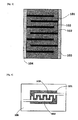
- Fig. 4 shows a schematic drawing of a piezoelectric surface acoustic wave (SAW) filter pertaining to an embodiment of the present invention.
- the piezoelectric surface acoustic wave filter pertaining to an embodiment of the present invention has a substrate 106, a piezoelectric ceramic layer 101 formed on the substrate 106, and a first electrode 102 and second electrode 103 placed in a manner facing each other and roughly flush with the piezoelectric ceramic layer 101 on the substrate 106.
- the piezoelectric surface acoustic wave filter pertaining to an embodiment of the present invention offers excellent mass-producibility compared to filters of the same type using the conventional LNKN not containing Li 3 NbO 4 crystal phase.
- Fig. 5 shows a schematic section view of a switching element using a flex-type piezoelectric actuator pertaining to an embodiment of the present invention.
- the switching element pertaining to an embodiment of the present invention has a substrate 106, a first electrode 102 formed on the substrate 106, a piezoelectric ceramic layer 101 formed on the first electrode 102, a second electrode 103 formed on the piezoelectric ceramic layer 101, an elastic body 107, and a contact 108.
- the switching element using a flex-type piezoelectric actuator pertaining to an embodiment of the present invention offers excellent mass-producibility compared to switching elements of the same type using the conventional LNKN not containing Li 3 NbO 4 crystal phase.
- the starting material Li 2 CO 3 a commercial Li 2 CO 3 product that had been pre-crushed for 24 hours in a ball mill and adjusted to an average particle size of 1 ⁇ m or less was used. Also for the starting material for depositing the Li 3 NbO 4 crystal phase, 0.2 mol of Li 2 CO 3 was weighed relative to 100 mol of the main constituent LNKN. Next, the weighed materials for the main constituent, and material for depositing the Li 3 NbO 4 crystal phase, were wet-mixed for approx. 24 hours in a ball mill to obtain a mixture. Next, this mixture was dried in an ambience of approx. 100°C, and then tentatively sintered at 700°C to 1000°C to obtain a tentatively sintered powder.
- this tentatively sintered powder was wet-crushed for approx. 24 hours in a ball mill, and then dried in an ambience of approx. 100°C to obtain a crushed powder.
- Ag 2 O was added by 0.1 mol, 0.25 mol, 0.50 mol and 1.00 mol to the obtained crushed powder, relative to 100 mol of the main constituent LNKN, and each mixture was wet-mixed in a ball mill for approx. 24 hours, to check the effect from containing Ag.
- each of these mixtures was dried in an ambience of approx. 100°C to obtain four types of Ag 2 O-mixed crushed powders, each with a different Ag 2 O content.
- each of these granularity-adjusted mixtures was molded using a single-axis molder at a pressure of 1000 kg/cm 2 , to obtain a disk-shaped molding of 10 mm in diameter and 0.5 mm in thickness.
- each of these moldings was sintered in air at temperatures of 960°C to 1100°C, to obtain four types of sintered compacts of piezoelectric ceramic, each with a different Ag content (corresponding to Sample Nos. 3 to 6 in Table 1).
- a piezoelectric ceramic having the same composition as Sample No. 1 representing a comparative example, and the same composition as Sample No. 2 representing an example of the present invention were prepared at multiple sintering temperatures and the sintered compact prepared at each sintering temperature was measured for sintering density.
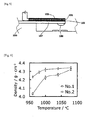
- Fig. 6 is a graph showing the measured dependence of sintering density on sintering temperature. As is evident from Fig. 6 , the piezoelectric ceramic having the same composition as Sample No. 1 could not be densely sintered unless the sintering temperature was raised to 1080°C, but the piezoelectric ceramic having the same composition as Sample No.
- Sample Nos. 1 to 6 in Table 1 contained the Li 3 NbO 4 crystal phase was checked in the following manner.
- each sample that had been stripped of electrodes was crushed for 30 minutes in ethanol using an agate mortar.
- Each of the crushed samples was measured for XRD using the X-ray diffraction method. This measurement was performed according to the concentration method using the RINT-2500PC X-ray diffractometer by Rigaku.
- Cu-K ⁇ line was used as the line source, while the applied voltage was 50 kV and applied current was 100 mA.
- the 2 ⁇ / ⁇ method was used to take a measurement every second at a pitch of 0.02° according to the fixed time method in the range of 10° ⁇ 2 ⁇ ⁇ 60°.
- the top graph in Fig. 7 shows the X-ray diffraction profile of Sample No. 1 measured as above, while the bottom graph in Fig. 7 shows the X-ray diffraction profile of Sample No. 2.
- Fig. 7 shows enlarged near-background peaks in the diffraction profiles of 10° ⁇ 2 ⁇ 2 ⁇ ⁇ 35°.
- the profile of Sample No. 2 has peaks of Li 3 NbO 4 crystal phase as indicated by ⁇ (star).
- Fig. 8 shows the X-ray diffraction profiles of Sample Nos. 2 to 6.
- the graph line of reference symbol a in Fig. 8 represents the profile of Sample No. 2
- graph line of reference symbol b represents the profile of Sample No. 3
- graph line of reference symbol c represents the profile of Sample No. 4
- graph line of reference symbol d represents the profile of Sample No. 5
- graph line of reference symbol e represents the profile of Sample No. 6.
- piezoelectric ceramics containing Ag 2 O deposited more Li 3 NbO 4 crystal phase as the Ag 2 O content increased.
- the Li 3 NbO 4 crystal phase can be deposited on the main phase LNKN when Ag 2 O is contained.
- Sample Nos. 1 to 6 were each measured for the electrical characteristics shown in Table 2 using the resonance-antiresonance method according to the JEITA EM-4501 standard set by the Japan Electronics and Information Technology Industries Association. This measurement was performed using an impedance analyzer (YHP4194A manufactured by Yokogawa-Hewlett-Packard). Also, a d 33 meter (ZJ-6B manufactured by the Institute of Acoustics, Chinese Academy of Science) was used to evaluate piezoelectric characteristics in terms of piezoelectric constant d 33 . Each coefficient was measured on samples of Sample Nos. 1 and 2 sintered at 1000°C and 1080°C, while each coefficient was measured on samples of Sample Nos. 3 to 6 sintered at 1000°C.
- ⁇ 33 T / ⁇ 0 represents the specific dielectric constant after polarization, measured in the direction in which electric field was applied during the polarization;
- kp represents the electro-mechanical coupling coefficient measured in the diameter direction of disk-shaped piezoelectric ceramics after polarization;
- Y 11 E represents the Young's modulus measured in the direction vertical to the direction in which electric field was applied during the polarization;
- d 31 represents the piezoelectric constant measured in the direction vertical to the direction in which electric field was applied during the polarization;
- d 33 represents the piezoelectric constant measured in parallel with the direction in which electric field was applied during the polarization.
- a dense sintered compact was obtained at around 1000°C by compounding excessive Li 2 CO 3 beyond the stoichiometric ratio of LNKN and thereby depositing the Li 3 NbO 4 crystal phase, and that the resulting piezoelectric characteristics were not compromised in any way compared to when the stoichiometric ratio of LNKN was followed in the compounding (Sample 1).
- the Ag 2 O content in Ag 2 O-containing piezoelectric ceramics is preferably 0.1 mol or more and 0.5 mol or less in equivalent Ag 2 O relative to 100 mol of the main constituent LNKN.
- testing of the effects of the present invention according to the same procedure on piezoelectric ceramics expressed by the composition formula ⁇ Li x [Na 1-y K y ] 1-x ⁇ a NbO 3 in the formula, 0.0 ⁇ x ⁇ 0.20, 0 ⁇ y ⁇ 1, and 1.0 ⁇ a ⁇ 1.01), other than those shown in the above example, confirmed similar effects.
Landscapes
- Engineering & Computer Science (AREA)
- Chemical & Material Sciences (AREA)
- Ceramic Engineering (AREA)
- Physics & Mathematics (AREA)
- Acoustics & Sound (AREA)
- Manufacturing & Machinery (AREA)
- Materials Engineering (AREA)
- Structural Engineering (AREA)
- Organic Chemistry (AREA)
- Inorganic Chemistry (AREA)
- Compositions Of Oxide Ceramics (AREA)
Abstract
Description
- The present invention relates to a piezoelectric ceramic of alkali-containing niobate-type perovskite structure, not containing heavy metal elements such as lead; a piezoelectric ceramic component using such piezoelectric ceramic, including a piezoelectric sound generator, piezoelectric sensor, piezoelectric actuator, piezoelectric transformer, and piezoelectric supersonic motor; and a piezoelectric device using such piezoelectric ceramic component.
- Piezoelectric ceramics are a type of piezoelectric material that converts electrical energy to mechanical energy, and mechanical energy to electrical energy, and they are applied in many electronic devices. Among such piezoelectric ceramics, binary Pb-containing piezoelectric ceramics constituted by the two constituents of PbTiO3 and PbZrO3 (hereinafter referred to as "PZT") and tertiary Pb-containing piezoelectric ceramics containing Pb(Mg1/3Nb2/3)O3 or Pb(Zn1/3Nb2/3)O3 as the third constituent, are known. Such PZT provides high piezoelectric effect and is widely used as piezoelectric ceramic components. However, piezoelectric ceramics whose main constituent is PZT present problems in that they have high environmental burdens in the form of volatilization of PbO in the production process, flow-out of Pb constituent due to exposure to acid rain, and the like.
- Accordingly, non-Pb piezoelectric ceramics containing no lead are pursued. As disclosed examples of Pb-free piezoelectric ceramics, Nature, 432 (4), 2004, pp. 84-87 (Non-patent Literature 1) and Applied Physics Letters 85 (18), 2004, pp. 4121-41232 (Non-patent Literature 2) disclose piezoelectric ceramics providing piezoelectric effect equivalent to PZT, having an alkali-containing niobate perovskite structure.
- Such piezoelectric ceramics having an alkali-containing niobate perovskite structure are also disclosed in
Japanese Patent Laid-open No. 2002-068835 Japanese Patent Laid-open No. 2003-342069 Japanese Patent Laid-open No. 2004-300012 Japanese Patent Laid-open No. 2008-169113 - Among the piezoelectric ceramics expressed by the above general formula, however, antimony (Sb) belongs to the heavy metal class and presents concerns over toxicity to the human body. Accordingly, piezoelectric ceramics not containing antimony are desired. Also, while tantalum (Ta) can lower the Curie temperature, raise the dielectric constant of piezoelectric ceramics, and enhance the piezoelectric constant and other characteristics, use of tantalum raises the sintering temperature needed to obtain dense ceramics.
- As explained above, piezoelectric ceramics having an alkali-containing niobate perovskite structure, not containing Sb or Ta and having Li, Na, K, Nb and O as constituent elements (hereinafter referred to as "LNKN"), offer excellent piezoelectric characteristics, but the sintering property is poorer than Pb-containing piezoelectric ceramics. For example, Li0.06Na0.47K0.47NbO3, which is a type of LNKN, exhibits excellent characteristics as evident from displacement characteristics d33 in the polarization axis direction of 235 pC/N, but it must be sintered at temperatures of 1050°C to 1100°C in order to obtain a dense sintered compact, as disclosed in Non-patent Literature 2. Sintering at high temperatures causes alkali metal elements to evaporate easily and piezoelectric effect may deteriorate. Accordingly, sintering temperatures must be controlled precisely in order to obtain ceramics having sufficiently high piezoelectric effect.
-
Japanese Patent Laid-open No. 2008-207999 - Furthermore,
Japanese Patent Laid-open No. 2004-115293 -
- Patent Literature 1:
Japanese Patent Laid-open No. 2002-068835 - Patent Literature 2:
Japanese Patent Laid-open No. 2003-342069 - Patent Literature 3:
Japanese Patent Laid-open No. 2004-300012 - Patent Literature 4:
Japanese Patent Laid-open No. 2008-169113 - Patent Literature 5:
Japanese Patent Laid-open No. 2008-207999 - Patent Literature 6:
Japanese Patent Laid-open No. 2004-115293 -
- Non-patent Literature 1: Nature, 432 (4), 2004, pp. 84-87
- Non-patent Literature 2: Applied Physics Letters 85 (18), 2004, pp. 4121-4123
- As mentioned above, sintering temperatures of 1050°C to 1100°C are needed to obtain a dense sintered compact of LNKN, and therefore LNKN is not an appropriate alternative to Pb-containing piezoelectric ceramics providing a dense sintered compact at around 1000°C and offering high piezoelectric characteristics. To use LNKN as a piezoelectric ceramic for a laminated piezoelectric ceramic component having precious-metal or base-metal electrodes, for example, desirably a sintering temperature of approx. 1000°C is used to suppress contraction of internal electrodes. However, no technology is known to date by which a dense sintered compact of LNKN can be obtained at approx. 1000°C.
- The object of various embodiments of the present invention is to provide a ceramic compound whose main constituent is LNKN, which can be sintered at around 1000°C without compromising piezoelectric characteristics.
- The inventors of the present invention found that, by depositing the Li3NbO4 crystal phase on a piezoelectric ceramic having an alkali-containing niobate perovskite structure and Li, Na, K, Nb and O as constituent elements, the piezoelectric ceramic could be densely sintered at around 1000°C.
- A piezoelectric ceramic in an embodiment of the present invention has an alkali-containing niobate perovskite structure and Li, Na, K, Nb and O as constituent elements, wherein such ceramic holds a crystal phase expressed by the composition formula Li3NbO4.
- Embodiments of the present invention provide a ceramic compound whose main constituent is LNKN, which can be sintered at around 1000°C without compromising piezoelectric characteristics.
-
- [
Fig. 1 ] is a schematic drawing showing the crystal structure of an ABO3 type perovskite structure. - [
Fig. 2 ] is a side view showing an example of a piezoelectric device conforming to the present invention. - [
Fig. 3 ] is a schematic section view showing an example of a piezoelectric device conforming to the present invention. - [
Fig. 4 ] is a plan view showing an example of a piezoelectric device conforming to the present invention. - [
Fig. 5 ] is a schematic section view showing an example of a piezoelectric device conforming to the present invention. - [
Fig. 6 ] is a graph showing the dependence of sintering density on sintering temperature for each of Sample No. 1 and Sample No. 2. - [
Fig. 7 ] is graphs showing X-ray diffraction profiles of Sample No. 1 (top) and Sample No. 2 (bottom). - [
Fig. 8 ] is a graph showing X-ray diffraction profiles of Sample Nos. 2 to 6. - The present application for patent claims priority based on
Japanese Patent Application No. 2010-288242 - Piezoelectric ceramic materials in various embodiments of the present invention are mainly constituted by a piezoelectric ceramic having an alkali-containing niobate perovskite structure and Li, Na, K, Nb and O as constituent elements (i.e., LNKN). The alkali-containing niobate perovskite structure is a type of ABO3-type perovskite structure, where the A site has K, Na, Li or other alkali metal element, while the B site has Nb.
Fig. 1 shows a schematic drawing of the perovskite structure. As illustrated, the perovskite structure has a unit structure where six O's are positioned around the B site and 12 O's are positioned around the A site, and crystal is formed by a cyclical succession of these unit structures. With the perovskite structure, all site positions are occupied by the corresponding elements and a stable structure is obtained when the composition ratio (mol ratio) of the element occupying the A site and element occupying the B site becomes 1:1 according to the stoichiometric ratio of the perovskite structure. However, the composition of the sintered compact of LNKN may vary by a maximum of 2% or so from the composition according to the stoichiometric ratio due to elution of K, Na and Li, volatilization of K, Na and Li in the tentative sintering process or sintering process, and so on. How much these constituent elements vary changes depending on the material, timing of synthesis, and synthesis process. - Accordingly, in the initial compounding, the compounding ratio of the material for the element occupying the A site (K, Na or Li) to the material for the element occupying the B site is increased above the ideal compounding ratio specified by the stoichiometric ratio, so that the composition ratio of the element occupying the A site and element occupying the B site will become the stoichiometric ratio of 1:1 in the finally obtained sintered compact. For the finally obtained LNKN to have high piezoelectric effect, however, desirably the composition ratio of the element contained at the A site and element contained at the B site after sintering is in the range of 0.98 < A / B < 1.01. If the compounding ratio of the material for the K, Na or Li element occupying the A site is increased, however, K2O, Na2O, Li2O or other oxide or K2CO3, Na2CO3, Li2CO3 or other carbonate compound may deposit, which may lower the specific resistivity of the obtained piezoelectric ceramic or cause deliquescence.
- In an embodiment of the present invention, a piezoelectric ceramic having high sintering property can be obtained by depositing Li3NbO4 on the main constituent of LNKN. In an embodiment, Li3NbO4 can be deposited on the main constituent of LNKN by compounding the material for Li such as Li2CO3, etc., in such a way that Li becomes excessive beyond the stoichiometric ratio of LNKN. In an embodiment, a commercial Li2CO3 product is pre-crushed for 24 hours in a ball mill to an average particle size of 1 µm or less and the obtained Li2CO3 can be used as the starting material. Many commercial Li2CO3 products have an average particle size of 5 µm or more and when such Li2CO3 with an average particle size of 5µm or more is used, deposition of Li3NbO4 becomes difficult. With the piezoelectric ceramic pertaining to an embodiment of the present invention, Li3NbO4 is deposited on the main constituent of LNKN to allow for easy sintering at around 1000°C and obtain a piezoelectric ceramic whose piezoelectric characteristics are less compromised than a piezoelectric ceramic not containing the Li3NbO4 crystal phase. With the piezoelectric ceramic pertaining to an embodiment of the present invention, the Li3NbO4 crystal phase containing an excessive alkali constituent compared to the main constituent of the perovskite structure that contains the alkali constituent and niobium at a ratio of 1:1, is deposited on the main constituent, and this probably allows the alkali constituent that volatilizes from the perovskite structure during sintering to be supplemented with surplus Li, to compensate for sintering property.
- In an embodiment, the Li3NbO4 crystal phase may be the cubic crystal phase described under PDF-01-082-1198 or PDF-01-075-0902 in ICSD (Inorganic Crystal Structure Database). In an embodiment, the lattice constant of the Li3NbO4 crystal phase is 8.412 Å or 8.429 Å. Here, the lattice constants and their respective diffraction line intensity ratios are affected by the crystallization property of the Li3NbO4 crystal phase, defect factors in the crystal structure, etc., and the lattice constant may change at the second decimal place and below, for example. However, this does not pose an impediment to the present invention.
- A piezoelectric ceramic pertaining to an embodiment of the present invention may be expressed by the composition formula {Lix[NayK1-y]1-x}aNbO3 (in the formula, 0.0 < x ≤ 0.20, 0 ≤ y ≤ 1, and 1.0 ≤ a ≤ 1.01). A piezoelectric ceramic in an embodiment is expressed by the composition formula {Lix[NayK1-y]1-x}aNbO3 (in the formula, 0.03 ≤ x ≤ 0.10, 0.40 ≤ y ≤ 0.60, and 1.0 ≤ a ≤ 1.01). By adjusting the composition ratio of the constituent elements of a piezoelectric ceramic pertaining to an embodiment of the present invention, to the ranges specified by these composition formulas, piezoelectric characteristics equivalent to those of Pb-containing piezoelectric ceramics can be obtained, and dense sintering becomes possible at around 1000°C. As a result, a Pb-free piezoelectric ceramic that can substitute a Pb-containing piezoelectric ceramic used for piezoelectric devices can be provided.
- A piezoelectric ceramic pertaining to an embodiment of the present invention may contain Ag by 0.1 mol or more to 0.5 mol in equivalent Ag2O, relative to 100 mol of the main constituent of LNKN expressed by {Lix[NayK1-y]1-x}aNbO3. This way, deposition of the Li3NbO4 crystal phase can be promoted further and sintering can be performed easily without compromising piezoelectric characteristics. In an embodiment, Ag is contained by 0.1 mol or more to 0.25 mol or less in equivalent Ag2O relative to 100 mol of the main constituent. This way, drop in specific resistivity caused by an increase in Ag content can be suppressed. When Ag2O is added, a (Li,Ag)3NbO4 crystal phase, resulting from partial substitution of Li by Ag in the Li3NbO4 crystal phase, is deposited, but the obtained effect is the same as when only the Li3NbO4 crystal phase is deposited. This is because the Li3NbO4 crystal phase and (Li,Ag)3NbO4 crystal phase have the same symmetry that determines the crystal system, lattice constant, and other crystal properties.
- Patent Literature 4 discloses adding Ag to the main constituent containing Ta and Sb, but a piezoelectric ceramic pertaining to an embodiment of the present invention is distinguished from the piezoelectric ceramic in Patent Literature 4 in that it does not contain Ta or Sb.
- A piezoelectric ceramic in an embodiment of the present invention contains at least one type of first transition element from among Sc, Ti, V, Cr, Mn, Fe, Co, Ni, Cu and Zn. This makes it possible to control the sintering temperature, control the growth of particles, and control the dielectric breakdown in a high electric field.
- A piezoelectric ceramic in an embodiment of the present invention contains at least one type of second transition element from among Y, Zr, Mo, Ru, Rh and Pd. This makes it possible to control the sintering temperature, control the growth of particles, and control the dielectric breakdown in a high electric field.
- A piezoelectric ceramic in an embodiment of the present invention contains at least one type of third transition element from among La, Ce, Pr, Nd, Sm, Eu, Gd, Tb, Dy, Ho, Er, Tm, Yb, Lu, Hf, W, Re, Os, Ir, Pt and Au. This makes it possible to control the sintering temperature, control the growth of particles, and control the dielectric breakdown in a high electric field.
- A piezoelectric ceramic in an embodiment of the present invention contains elements selected from the first transition elements and second transition elements, elements selected from the first transition elements and third transition elements, elements selected from the second transition elements and third transition elements, or elements selected from the first transition elements, second transition elements and third transition elements.
- Next, piezoelectric ceramic components using a piezoelectric ceramic pertaining to an embodiment of the present invention, as well as piezoelectric devices using such piezoelectric ceramic components, are explained by referring to
Figs. 2 to 5 . The piezoelectric ceramic component inFig. 2 has a sheet-shaped piezoelectricceramic layer 101,first electrode 102, andsecond electrode 103. Thefirst electrode 102 andsecond electrode 103 are placed in a manner facing each other via the piezoelectricceramic layer 101. The piezoelectricceramic layer 101 is made of a piezoelectric ceramic pertaining to an embodiment of the present invention, and specifically it is made of LNKN from which the crystal phase expressed by the composition formula Li3NbO4 is deposited. In an embodiment, the piezoelectricceramic layer 101 is prepared by mixing a material mixture powder of a piezoelectric ceramic with a binder and then forming the mixture into a sheet-shaped molding and sintering the molding. Next, a conductive paste using Cu, Ag, Au, Pt or other conductor is applied on both sides of this piezoelectricceramic layer 101 and this conductive paste is baked to form thefirst electrode 102 andsecond electrode 103. The piezoelectricceramic layer 101 is densely sintered at around 1000°C, so it offers excellent mass-producibility compared to when the conventional LNKN not containing Li3NbO4 crystal phase is used. -
Fig. 3 is a schematic section view of a laminated piezoelectric ceramic component pertaining to an embodiment of the present invention. As illustrated, the laminated piezoelectric ceramic component pertaining to an embodiment of the present invention includes a piezoelectricceramic layer 101, multiplefirst electrodes 102, multiplesecond electrodes 103, a firstterminal electrode 104 electrically connected to each of thefirst electrodes 102, and a secondterminal electrode 105 electrically connected to each of thesecond electrodes 103. Each of thefirst electrodes 102 is positioned in a manner facing the adjacentsecond electrode 103 via the piezoelectricceramic layer 101. This laminated piezoelectric ceramic component is used as a laminated piezoelectric actuator, for example. Since this piezoelectricceramic layer 101 can be densely sintered at around 1000°C, the laminated piezoelectric ceramic component pertaining to an embodiment of the present invention offers excellent mass-producibility compared to components of the same type using the conventional LNKN not containing Li3NbO4 crystal phase. -
Fig. 4 shows a schematic drawing of a piezoelectric surface acoustic wave (SAW) filter pertaining to an embodiment of the present invention. As illustrated, the piezoelectric surface acoustic wave filter pertaining to an embodiment of the present invention has asubstrate 106, a piezoelectricceramic layer 101 formed on thesubstrate 106, and afirst electrode 102 andsecond electrode 103 placed in a manner facing each other and roughly flush with the piezoelectricceramic layer 101 on thesubstrate 106. Since the piezoelectricceramic layer 101 can be densely sintered at around 1000°C, the piezoelectric surface acoustic wave filter pertaining to an embodiment of the present invention offers excellent mass-producibility compared to filters of the same type using the conventional LNKN not containing Li3NbO4 crystal phase. -
Fig. 5 shows a schematic section view of a switching element using a flex-type piezoelectric actuator pertaining to an embodiment of the present invention. As illustrated, the switching element pertaining to an embodiment of the present invention has asubstrate 106, afirst electrode 102 formed on thesubstrate 106, a piezoelectricceramic layer 101 formed on thefirst electrode 102, asecond electrode 103 formed on the piezoelectricceramic layer 101, anelastic body 107, and acontact 108. Since the piezoelectricceramic layer 101 can be densely sintered at around 1000°C, the switching element using a flex-type piezoelectric actuator pertaining to an embodiment of the present invention offers excellent mass-producibility compared to switching elements of the same type using the conventional LNKN not containing Li3NbO4 crystal phase. - An example of the present invention is explained below, but it should be noted that the present invention is not limited to this example in any way. First, Li2CO3, Na2CO3 (or NaHCO3), K2CO3 (or KHCO3), and Nb2O5 of 99% or higher in purity were prepared as the starting materials for the main constituent LNKN, and weighed to the stoichiometric ratios of x = 0.066, y = 0.557 and a = 1.0 in the composition formula {Lix[Na1-yKy]1-x}aNbO3 (in the formula, 0.0 ≤ x ≤ 0.20, 0 ≤ y ≤ 1, and 1.0 ≤ a ≤ 1.01). For the starting material Li2CO3, a commercial Li2CO3 product that had been pre-crushed for 24 hours in a ball mill and adjusted to an average particle size of 1 µm or less was used. Also for the starting material for depositing the Li3NbO4 crystal phase, 0.2 mol of Li2CO3 was weighed relative to 100 mol of the main constituent LNKN. Next, the weighed materials for the main constituent, and material for depositing the Li3NbO4 crystal phase, were wet-mixed for approx. 24 hours in a ball mill to obtain a mixture. Next, this mixture was dried in an ambience of approx. 100°C, and then tentatively sintered at 700°C to 1000°C to obtain a tentatively sintered powder. Next, this tentatively sintered powder was wet-crushed for approx. 24 hours in a ball mill, and then dried in an ambience of approx. 100°C to obtain a crushed powder. Thereafter, Ag2O was added by 0.1 mol, 0.25 mol, 0.50 mol and 1.00 mol to the obtained crushed powder, relative to 100 mol of the main constituent LNKN, and each mixture was wet-mixed in a ball mill for approx. 24 hours, to check the effect from containing Ag. Next, each of these mixtures was dried in an ambience of approx. 100°C to obtain four types of Ag2O-mixed crushed powders, each with a different Ag2O content. Next, an organic binder was added to and mixed with each of these Ag2O-mixed crushed powders, and each mixture was passed through a 60-mesh sieve to adjust the granularity. Next, each of these granularity-adjusted mixtures was molded using a single-axis molder at a pressure of 1000 kg/cm2, to obtain a disk-shaped molding of 10 mm in diameter and 0.5 mm in thickness. Next, each of these moldings was sintered in air at temperatures of 960°C to 1100°C, to obtain four types of sintered compacts of piezoelectric ceramic, each with a different Ag content (corresponding to Sample Nos. 3 to 6 in Table 1).
- Additionally, in the process of preparing these piezoelectric ceramics corresponding to Sample Nos. 3 to 6, only the Ag2O mixing step was skipped to prepare a piezoelectric ceramic not containing Ag2O (corresponding to Sample No. 2 in Table 1). Also, in the process of preparing this piezoelectric ceramic corresponding to Sample No. 2, the step to mix Li2CO3 for depositing the Li3NbO4 crystal phase was skipped to prepare a piezoelectric ceramic not containing excessive Li2CO3 for depositing the Li3NbO4 crystal phase (but containing Li2CO3 as the material for the main constituent LNKN) (corresponding to Sample No. 1 in Table 1).
- Next, a silver paste was applied on both surfaces of each of the six types of piezoelectric ceramic obtained as mentioned above, and this silver paste was baked at 850°C to form silver electrodes. Next, approx. 3 to 4 kV/mm of electric field equal to or above the coercive electric field was applied, in the form of DC voltage, for 15 minutes in insulating oil to each of these piezoelectric ceramics on which silver electrodes were formed, to implement polarization. Thereafter, each sample was kept stationary overnight, to obtain Sample Nos. 1 to 6 of piezoelectric ceramics. The compositions of thus prepared Sample Nos. 1 to 6 of piezoelectric ceramics are shown in Table 1.
-
[Table 1] Sample No. x y Amount of excessive Li2CO3 (mol%) Ag2O content (mol%) 1
0.066 0.557 0 0 2 0.066 0.557 0.2 0 3 0.066 0.557 0.2 0.1 4 0.066 0.557 0.2 0.25 5 0.066 0.557 0.2 0.50 6
0.066 0.557 0.2 1.00 are outside the scope of the present invention. - Next, a piezoelectric ceramic having the same composition as Sample No. 1 representing a comparative example, and the same composition as Sample No. 2 representing an example of the present invention, were prepared at multiple sintering temperatures and the sintered compact prepared at each sintering temperature was measured for sintering density.
Fig. 6 is a graph showing the measured dependence of sintering density on sintering temperature. As is evident fromFig. 6 , the piezoelectric ceramic having the same composition as Sample No. 1 could not be densely sintered unless the sintering temperature was raised to 1080°C, but the piezoelectric ceramic having the same composition as Sample No. 2 to which excessive Li2CO3 was added was such that its sintering accelerated at around 1000°C and sintering density became higher. Both samples melted partially when sintered at temperatures of 1080°C and above. Accordingly, it was concluded that a uniform sintered compact could not be obtained at 1080°C or above. - Next, whether or not Sample Nos. 1 to 6 in Table 1 contained the Li3NbO4 crystal phase was checked in the following manner. First, each sample that had been stripped of electrodes was crushed for 30 minutes in ethanol using an agate mortar. Each of the crushed samples was measured for XRD using the X-ray diffraction method. This measurement was performed according to the concentration method using the RINT-2500PC X-ray diffractometer by Rigaku. Cu-Kα line was used as the line source, while the applied voltage was 50 kV and applied current was 100 mA. The 2 θ/θ method was used to take a measurement every second at a pitch of 0.02° according to the fixed time method in the range of 10° ≤ 2θ ≤ 60°.
- The top graph in
Fig. 7 shows the X-ray diffraction profile of Sample No. 1 measured as above, while the bottom graph inFig. 7 shows the X-ray diffraction profile of Sample No. 2.Fig. 7 shows enlarged near-background peaks in the diffraction profiles of 10° ≤ 2θ 2θ ≤ 35°. As is evident fromFig. 7 , the profile of Sample No. 2 has peaks of Li3NbO4 crystal phase as indicated by ☆ (star). -
Fig. 8 shows the X-ray diffraction profiles of Sample Nos. 2 to 6. The graph line of reference symbol a inFig. 8 represents the profile of Sample No. 2, graph line of reference symbol b represents the profile of Sample No. 3, graph line of reference symbol c represents the profile of Sample No. 4, graph line of reference symbol d represents the profile of Sample No. 5, and graph line of reference symbol e represents the profile of Sample No. 6. As illustrated, piezoelectric ceramics containing Ag2O deposited more Li3NbO4 crystal phase as the Ag2O content increased. In other words, the Li3NbO4 crystal phase can be deposited on the main phase LNKN when Ag2O is contained. - Next, Sample Nos. 1 to 6 were each measured for the electrical characteristics shown in Table 2 using the resonance-antiresonance method according to the JEITA EM-4501 standard set by the Japan Electronics and Information Technology Industries Association. This measurement was performed using an impedance analyzer (YHP4194A manufactured by Yokogawa-Hewlett-Packard). Also, a d33 meter (ZJ-6B manufactured by the Institute of Acoustics, Chinese Academy of Science) was used to evaluate piezoelectric characteristics in terms of piezoelectric constant d33. Each coefficient was measured on samples of Sample Nos. 1 and 2 sintered at 1000°C and 1080°C, while each coefficient was measured on samples of Sample Nos. 3 to 6 sintered at 1000°C. Here, ε33 T/ε0 represents the specific dielectric constant after polarization, measured in the direction in which electric field was applied during the polarization; kp represents the electro-mechanical coupling coefficient measured in the diameter direction of disk-shaped piezoelectric ceramics after polarization; Y11 E represents the Young's modulus measured in the direction vertical to the direction in which electric field was applied during the polarization; d31 represents the piezoelectric constant measured in the direction vertical to the direction in which electric field was applied during the polarization; and d33 represents the piezoelectric constant measured in parallel with the direction in which electric field was applied during the polarization.
-
[Table 2] Sample No. Sintering temperature ε33 T/ε0 kp (%) Y11 E
(x1010N/m2)d31(pC/N) d33(pC/N) 11000°C Could not be polarized 1080°C 960 41 8.3 -71 185 2 1000°C 960 42 8.1 -81 190 1080°C 920 41 8.5 -72 180 3 1000°C 990 41 7.9 -80 195 4 1000°C 945 40 7.5 -79 205 5 1000°C 465 39 9.1 -50 150 61000°C 405 31 9.2 -39 110 - Similarly with Sample Nos. 3 to 6, a sufficiently dense sintered compact was obtained when sintered at 1000°C. Among others, Sample Nos. 3 and 4 had a lower Young's modulus although the electro-mechanical coupling coefficient was not affected, and therefore these piezoelectric ceramics were more prone to deformation. This resulted in an improvement of d33. Also with Sample No. 5, the electro-mechanical coupling coefficient was not affected. As for Sample No. 6, both the specific dielectric constant and electro-mechanical coupling coefficient dropped significantly and the Young's modulus rose, and consequently both the piezoelectric constants d31 and d33 dropped significantly.
- Based on the above results, it is clear that the Ag2O content in Ag2O-containing piezoelectric ceramics is preferably 0.1 mol or more and 0.5 mol or less in equivalent Ag2O relative to 100 mol of the main constituent LNKN. In addition, testing of the effects of the present invention according to the same procedure on piezoelectric ceramics expressed by the composition formula {Lix[Na1-yKy]1-x}aNbO3 (in the formula, 0.0 < x ≤ 0.20, 0 ≤ y ≤ 1, and 1.0 ≤ a ≤ 1.01), other than those shown in the above example, confirmed similar effects.
-
- 101:
- Piezoelectric ceramic layer
- 102:
- First electrode
- 103:
- Second electrode
- 104:
- First terminal electrode
- 105:
- Second terminal electrode
- 106:
- Substrate
- 107:
- Elastic body
- 108:
- Contact
Claims (8)
- A piezoelectric ceramic having an alkali-containing niobate perovskite structure
and Li, Na, K, Nb and O as constituent elements, the piezoelectric ceramic characterized by holding a crystal phase expressed by a composition formula Li3NbO4. - A piezoelectric ceramic according to Claim 1, characterized by being expressed by
a composition formula {Lix[NayK1-y]1-x}aNbO3 (in the formula, 0 < x ≤ 0.20, 0 ≤ y ≤ 1, and 1.0 ≤ a ≤ 1.01). - A piezoelectric ceramic according to Claim 2, characterized by containing Ag by 0.1 mol or more and 0.5 mol or less in equivalent Ag2O relative to 100 mol of the piezoelectric ceramic according to Claim 2.
- A piezoelectric ceramic component having a first electrode and a second
electrode facing each other via a piezoelectric ceramic layer, the piezoelectric ceramic component characterized in that the piezoelectric ceramic layer is formed by a piezoelectric ceramic according to any one of Claims 1 to 3. - A piezoelectric ceramic component having multiple first electrodes and multiple
second electrodes alternately layered via piezoelectric ceramic layers, as well as a first terminal electrode that electrically connects to the first electrodes and a second terminal electrode that electrically connects to the second electrodes, the piezoelectric ceramic component characterized in that the piezoelectric ceramic layer is formed by a piezoelectric ceramic according to any one of Claims 1 to 3. - A piezoelectric ceramic component having a substrate with a piezoelectric ceramic
layer, as well as a first electrode and a second electrode placed on top of the piezoelectric ceramic layer in a manner facing each other, the piezoelectric ceramic component characterized in that the piezoelectric ceramic layer is formed by a piezoelectric ceramic according to any one of Claims 1 to 3. - A piezoelectric ceramic component having multiple first electrodes and multiple
second electrodes layered alternately on a substrate with piezoelectric ceramic layers, as well as a first terminal electrode that electrically connects to the first electrodes and a second terminal electrode that electrically connects to the second electrodes, the piezoelectric ceramic component characterized in that the piezoelectric ceramic layer is formed by a piezoelectric ceramic according to any one of Claims 1 to 3. - A piezoelectric device characterized by using a piezoelectric ceramic component
according to any one of Claims 4 to 7.
Applications Claiming Priority (2)
| Application Number | Priority Date | Filing Date | Title |
|---|---|---|---|
| JP2010288242 | 2010-12-24 | ||
| PCT/JP2011/078735 WO2012086449A1 (en) | 2010-12-24 | 2011-12-13 | Piezoelectric ceramic, piezoelectric ceramic component, and piezoelectric device in which piezoelectric ceramic component is used |
Publications (3)
| Publication Number | Publication Date |
|---|---|
| EP2676945A1 true EP2676945A1 (en) | 2013-12-25 |
| EP2676945A4 EP2676945A4 (en) | 2016-03-30 |
| EP2676945B1 EP2676945B1 (en) | 2019-11-20 |
Family
ID=46313728
Family Applications (1)
| Application Number | Title | Priority Date | Filing Date |
|---|---|---|---|
| EP11850112.1A Active EP2676945B1 (en) | 2010-12-24 | 2011-12-13 | Piezoelectric ceramic, piezoelectric ceramic component, and piezoelectric device in which piezoelectric ceramic component is used |
Country Status (5)
| Country | Link |
|---|---|
| US (1) | US9537082B2 (en) |
| EP (1) | EP2676945B1 (en) |
| JP (1) | JP5782457B2 (en) |
| CN (1) | CN103119002B (en) |
| WO (1) | WO2012086449A1 (en) |
Cited By (1)
| Publication number | Priority date | Publication date | Assignee | Title |
|---|---|---|---|---|
| RU2728056C1 (en) * | 2019-07-24 | 2020-07-28 | федеральное государственное автономное образовательное учреждение высшего образования "Южный федеральный университет" | Lead-free piezoelectric ceramic material |
Families Citing this family (8)
| Publication number | Priority date | Publication date | Assignee | Title |
|---|---|---|---|---|
| JP5704725B2 (en) * | 2012-08-24 | 2015-04-22 | 太陽誘電株式会社 | Piezoelectric ceramics and piezoelectric element |
| JP6039715B2 (en) * | 2015-02-18 | 2016-12-07 | 太陽誘電株式会社 | Piezoelectric ceramics and piezoelectric element |
| US11889767B2 (en) * | 2019-03-14 | 2024-01-30 | Taiyo Yuden Co., Ltd. | Multilayer piezoelectric ceramic and method for manufacturing same, multilayer piezoelectric element, as well as piezoelectric vibration apparatus |
| JP7548717B2 (en) | 2020-03-27 | 2024-09-10 | 太陽誘電株式会社 | Piezoelectric element and its manufacturing method |
| KR102710734B1 (en) * | 2020-07-21 | 2024-09-27 | 삼성전자주식회사 | Dielectric material, preparing method thereof, and device comprising dielectric material |
| JP7628013B2 (en) * | 2020-11-04 | 2025-02-07 | 太陽誘電株式会社 | Piezoelectric element, its manufacturing method, and piezoelectric vibration device |
| CN113560110B (en) * | 2021-08-04 | 2023-04-14 | 湖南省美程陶瓷科技有限公司 | A ceramic-metal composite atomizing sheet and its preparation method |
| JP2023090233A (en) * | 2021-12-17 | 2023-06-29 | 太陽誘電株式会社 | Piezoelectric/dielectric ceramics, piezoelectric elements and sounding bodies |
Family Cites Families (27)
| Publication number | Priority date | Publication date | Assignee | Title |
|---|---|---|---|---|
| JPS5630713B2 (en) | 1973-04-04 | 1981-07-16 | ||
| JPS5630713A (en) * | 1979-08-22 | 1981-03-27 | Hitachi Ltd | Large capacity transformer |
| JP3531803B2 (en) * | 1999-02-24 | 2004-05-31 | 株式会社豊田中央研究所 | Alkali metal containing niobium oxide based piezoelectric material composition |
| JP4417536B2 (en) * | 2000-07-31 | 2010-02-17 | 京セラ株式会社 | Piezoelectric ceramic and piezoelectric element |
| JP4929522B2 (en) | 2000-08-25 | 2012-05-09 | 株式会社豊田中央研究所 | Piezoelectric ceramic composition |
| JP4631246B2 (en) | 2002-03-20 | 2011-02-16 | 株式会社豊田中央研究所 | Piezoelectric ceramic composition, manufacturing method thereof, piezoelectric element and dielectric element |
| JP4001363B2 (en) * | 2002-04-11 | 2007-10-31 | Tdk株式会社 | Piezoelectric ceramic |
| JP4156461B2 (en) | 2002-07-16 | 2008-09-24 | 株式会社デンソー | Piezoelectric ceramic composition, method for producing the same, and piezoelectric element |
| US7101491B2 (en) | 2002-07-16 | 2006-09-05 | Denso Corporation | Piezoelectric ceramic composition and method of production of same, piezoelectric element, and dielectric element |
| JP4398635B2 (en) | 2002-09-24 | 2010-01-13 | 株式会社ノリタケカンパニーリミテド | Piezoelectric ceramics |
| JP4163068B2 (en) | 2003-01-23 | 2008-10-08 | 株式会社デンソー | Piezoelectric ceramic composition and piezoelectric element |
| JP5022926B2 (en) | 2003-01-23 | 2012-09-12 | 株式会社デンソー | Piezoelectric ceramic composition and piezoelectric element |
| CN100371298C (en) * | 2004-06-17 | 2008-02-27 | 株式会社电装 | Grain-oriented ceramics and method for producing the same |
| JP5365986B2 (en) * | 2006-04-13 | 2013-12-11 | 株式会社村田製作所 | Ceramic powder and method for producing ceramic powder |
| JP2008207999A (en) | 2007-02-27 | 2008-09-11 | Konica Minolta Holdings Inc | Method for manufacturing piezoelectric ceramic composition |
| JP5021452B2 (en) * | 2007-02-27 | 2012-09-05 | 日本碍子株式会社 | Piezoelectric / electrostrictive porcelain composition and piezoelectric / electrostrictive element |
| JP5044437B2 (en) * | 2007-03-20 | 2012-10-10 | 日本碍子株式会社 | Method for manufacturing piezoelectric / electrostrictive porcelain sintered body |
| EP2045846B1 (en) * | 2007-10-03 | 2017-06-07 | NGK Insulators, Ltd. | Piezoelectric/electrostrictive ceramic composition and piezoelectric/electrostrictive device |
| US8022604B2 (en) * | 2007-10-19 | 2011-09-20 | Ngk Insulators, Ltd. | (Li, Na, K)(Nb, Ta)O3 type piezoelectric/electrostrictive ceramic composition containing 30-50 mol% Ta and piezoelectric/electrorestrictive device containing the same |
| JP5021595B2 (en) * | 2007-10-19 | 2012-09-12 | 日本碍子株式会社 | Piezoelectric / electrostrictive porcelain composition and piezoelectric / electrostrictive element |
| JP2009242230A (en) * | 2008-03-14 | 2009-10-22 | Nagoya Institute Of Technology | Method for producing alkali niobate perovskite crystal |
| KR100966595B1 (en) * | 2008-04-11 | 2010-06-29 | 한국세라믹기술원 | Lead-free Piezoelectric Ceramics with Perovskite Structure and Its Manufacturing Method |
| JP2010225705A (en) * | 2009-03-20 | 2010-10-07 | Nippon Soken Inc | Multilayer piezoelectric element and method for manufacturing the same |
| EP2431343B1 (en) * | 2009-05-08 | 2016-09-14 | Taiyo Yuden Co., Ltd. | Piezoelectric ceramic, method for producing same, and piezoelectric device |
| JP2010288242A (en) | 2009-05-12 | 2010-12-24 | Sony Chemical & Information Device Corp | Antenna device |
| US9090512B2 (en) * | 2009-11-26 | 2015-07-28 | Toyama Prefecture | Anisotropically shaped powder and method for producing the same |
| US8961679B2 (en) * | 2010-05-20 | 2015-02-24 | Agency For Science, Technology And Research | Method for preparing a lead-free piezoelectric thin film |
-
2011
- 2011-12-13 WO PCT/JP2011/078735 patent/WO2012086449A1/en not_active Ceased
- 2011-12-13 JP JP2012549728A patent/JP5782457B2/en active Active
- 2011-12-13 CN CN201180044864.8A patent/CN103119002B/en active Active
- 2011-12-13 US US13/876,453 patent/US9537082B2/en active Active
- 2011-12-13 EP EP11850112.1A patent/EP2676945B1/en active Active
Non-Patent Citations (1)
| Title |
|---|
| See references of WO2012086449A1 * |
Cited By (1)
| Publication number | Priority date | Publication date | Assignee | Title |
|---|---|---|---|---|
| RU2728056C1 (en) * | 2019-07-24 | 2020-07-28 | федеральное государственное автономное образовательное учреждение высшего образования "Южный федеральный университет" | Lead-free piezoelectric ceramic material |
Also Published As
| Publication number | Publication date |
|---|---|
| EP2676945A4 (en) | 2016-03-30 |
| JP5782457B2 (en) | 2015-09-24 |
| EP2676945B1 (en) | 2019-11-20 |
| WO2012086449A1 (en) | 2012-06-28 |
| CN103119002B (en) | 2014-09-17 |
| US20130320815A1 (en) | 2013-12-05 |
| CN103119002A (en) | 2013-05-22 |
| JPWO2012086449A1 (en) | 2014-05-22 |
| US9537082B2 (en) | 2017-01-03 |
Similar Documents
| Publication | Publication Date | Title |
|---|---|---|
| EP2676945B1 (en) | Piezoelectric ceramic, piezoelectric ceramic component, and piezoelectric device in which piezoelectric ceramic component is used | |
| KR101191246B1 (en) | Piezoelectric ceramic, method for producing same, and piezoelectric device | |
| EP2316804B1 (en) | Piezoelectric ceramic, process for producing the piezoelectric ceramic, and piezoelectric device | |
| US8518290B2 (en) | Piezoelectric material | |
| EP2610233B1 (en) | Piezoelectric ceramic and piezoelectric device | |
| WO2006117952A1 (en) | Piezoelectric porcelain composition and piezoelectric ceramic electronic component | |
| EP3097064B1 (en) | Dielectric composition, dielectric element, electronic component and laminated electronic component | |
| EP3000795A1 (en) | Piezoelectric composition, piezoelectric element and sputtering target | |
| KR20150042075A (en) | Piezoelectric materials for low sintering | |
| KR101099980B1 (en) | Lead Free Piezoelectric Composition | |
| EP2690680B1 (en) | Piezoelectric ceramics and method for manufacturing the same | |
| JP2011088786A (en) | Piezoelectric ceramic | |
| JP5158516B2 (en) | Piezoelectric ceramic composition and piezoelectric element | |
| US7564176B2 (en) | Laminated piezoelectric element and production method of the same | |
| WO2001021548A1 (en) | Piezoelectric ceramic compositions and methods for production thereof | |
| KR20110123557A (en) | Lead Free Piezoelectric Composition |
Legal Events
| Date | Code | Title | Description |
|---|---|---|---|
| PUAI | Public reference made under article 153(3) epc to a published international application that has entered the european phase |
Free format text: ORIGINAL CODE: 0009012 |
|
| PUAB | Information related to the publication of an a document modified or deleted |
Free format text: ORIGINAL CODE: 0009199EPPU |
|
| PUAI | Public reference made under article 153(3) epc to a published international application that has entered the european phase |
Free format text: ORIGINAL CODE: 0009012 |
|
| 17P | Request for examination filed |
Effective date: 20130425 |
|
| AK | Designated contracting states |
Kind code of ref document: A1 Designated state(s): AL AT BE BG CH CY CZ DE DK EE ES FI FR GB GR HR HU IE IS IT LI LT LU LV MC MK MT NL NO PL PT RO RS SE SI SK SM TR |
|
| DAX | Request for extension of the european patent (deleted) | ||
| REG | Reference to a national code |
Ref country code: DE Ref legal event code: R079 Ref document number: 602011063563 Country of ref document: DE Free format text: PREVIOUS MAIN CLASS: C04B0035000000 Ipc: C04B0035495000 |
|
| RA4 | Supplementary search report drawn up and despatched (corrected) |
Effective date: 20160225 |
|
| RIC1 | Information provided on ipc code assigned before grant |
Ipc: H01L 41/187 20060101ALI20160219BHEP Ipc: C04B 35/495 20060101AFI20160219BHEP Ipc: H03H 9/02 20060101ALI20160219BHEP Ipc: H01H 57/00 20060101ALI20160219BHEP Ipc: H01L 41/43 20130101ALI20160219BHEP |
|
| STAA | Information on the status of an ep patent application or granted ep patent |
Free format text: STATUS: EXAMINATION IS IN PROGRESS |
|
| 17Q | First examination report despatched |
Effective date: 20180730 |
|
| GRAP | Despatch of communication of intention to grant a patent |
Free format text: ORIGINAL CODE: EPIDOSNIGR1 |
|
| STAA | Information on the status of an ep patent application or granted ep patent |
Free format text: STATUS: GRANT OF PATENT IS INTENDED |
|
| INTG | Intention to grant announced |
Effective date: 20190604 |
|
| GRAS | Grant fee paid |
Free format text: ORIGINAL CODE: EPIDOSNIGR3 |
|
| GRAA | (expected) grant |
Free format text: ORIGINAL CODE: 0009210 |
|
| STAA | Information on the status of an ep patent application or granted ep patent |
Free format text: STATUS: THE PATENT HAS BEEN GRANTED |
|
| AK | Designated contracting states |
Kind code of ref document: B1 Designated state(s): AL AT BE BG CH CY CZ DE DK EE ES FI FR GB GR HR HU IE IS IT LI LT LU LV MC MK MT NL NO PL PT RO RS SE SI SK SM TR |
|
| REG | Reference to a national code |
Ref country code: GB Ref legal event code: FG4D |
|
| RIN1 | Information on inventor provided before grant (corrected) |
Inventor name: DOSHIDA, YUTAKA Inventor name: SHIMIZU, HIROYUKI Inventor name: HATANO, KEIICHI |
|
| REG | Reference to a national code |
Ref country code: CH Ref legal event code: EP |
|
| REG | Reference to a national code |
Ref country code: IE Ref legal event code: FG4D |
|
| REG | Reference to a national code |
Ref country code: DE Ref legal event code: R096 Ref document number: 602011063563 Country of ref document: DE |
|
| REG | Reference to a national code |
Ref country code: AT Ref legal event code: REF Ref document number: 1204024 Country of ref document: AT Kind code of ref document: T Effective date: 20191215 |
|
| REG | Reference to a national code |
Ref country code: NL Ref legal event code: MP Effective date: 20191120 |
|
| REG | Reference to a national code |
Ref country code: LT Ref legal event code: MG4D |
|
| PG25 | Lapsed in a contracting state [announced via postgrant information from national office to epo] |
Ref country code: NO Free format text: LAPSE BECAUSE OF FAILURE TO SUBMIT A TRANSLATION OF THE DESCRIPTION OR TO PAY THE FEE WITHIN THE PRESCRIBED TIME-LIMIT Effective date: 20200220 Ref country code: FI Free format text: LAPSE BECAUSE OF FAILURE TO SUBMIT A TRANSLATION OF THE DESCRIPTION OR TO PAY THE FEE WITHIN THE PRESCRIBED TIME-LIMIT Effective date: 20191120 Ref country code: BG Free format text: LAPSE BECAUSE OF FAILURE TO SUBMIT A TRANSLATION OF THE DESCRIPTION OR TO PAY THE FEE WITHIN THE PRESCRIBED TIME-LIMIT Effective date: 20200220 Ref country code: SE Free format text: LAPSE BECAUSE OF FAILURE TO SUBMIT A TRANSLATION OF THE DESCRIPTION OR TO PAY THE FEE WITHIN THE PRESCRIBED TIME-LIMIT Effective date: 20191120 Ref country code: LV Free format text: LAPSE BECAUSE OF FAILURE TO SUBMIT A TRANSLATION OF THE DESCRIPTION OR TO PAY THE FEE WITHIN THE PRESCRIBED TIME-LIMIT Effective date: 20191120 Ref country code: GR Free format text: LAPSE BECAUSE OF FAILURE TO SUBMIT A TRANSLATION OF THE DESCRIPTION OR TO PAY THE FEE WITHIN THE PRESCRIBED TIME-LIMIT Effective date: 20200221 Ref country code: ES Free format text: LAPSE BECAUSE OF FAILURE TO SUBMIT A TRANSLATION OF THE DESCRIPTION OR TO PAY THE FEE WITHIN THE PRESCRIBED TIME-LIMIT Effective date: 20191120 Ref country code: LT Free format text: LAPSE BECAUSE OF FAILURE TO SUBMIT A TRANSLATION OF THE DESCRIPTION OR TO PAY THE FEE WITHIN THE PRESCRIBED TIME-LIMIT Effective date: 20191120 Ref country code: NL Free format text: LAPSE BECAUSE OF FAILURE TO SUBMIT A TRANSLATION OF THE DESCRIPTION OR TO PAY THE FEE WITHIN THE PRESCRIBED TIME-LIMIT Effective date: 20191120 |
|
| PG25 | Lapsed in a contracting state [announced via postgrant information from national office to epo] |
Ref country code: IS Free format text: LAPSE BECAUSE OF FAILURE TO SUBMIT A TRANSLATION OF THE DESCRIPTION OR TO PAY THE FEE WITHIN THE PRESCRIBED TIME-LIMIT Effective date: 20200320 Ref country code: HR Free format text: LAPSE BECAUSE OF FAILURE TO SUBMIT A TRANSLATION OF THE DESCRIPTION OR TO PAY THE FEE WITHIN THE PRESCRIBED TIME-LIMIT Effective date: 20191120 Ref country code: RS Free format text: LAPSE BECAUSE OF FAILURE TO SUBMIT A TRANSLATION OF THE DESCRIPTION OR TO PAY THE FEE WITHIN THE PRESCRIBED TIME-LIMIT Effective date: 20191120 |
|
| PG25 | Lapsed in a contracting state [announced via postgrant information from national office to epo] |
Ref country code: AL Free format text: LAPSE BECAUSE OF FAILURE TO SUBMIT A TRANSLATION OF THE DESCRIPTION OR TO PAY THE FEE WITHIN THE PRESCRIBED TIME-LIMIT Effective date: 20191120 |
|
| PG25 | Lapsed in a contracting state [announced via postgrant information from national office to epo] |
Ref country code: EE Free format text: LAPSE BECAUSE OF FAILURE TO SUBMIT A TRANSLATION OF THE DESCRIPTION OR TO PAY THE FEE WITHIN THE PRESCRIBED TIME-LIMIT Effective date: 20191120 Ref country code: DK Free format text: LAPSE BECAUSE OF FAILURE TO SUBMIT A TRANSLATION OF THE DESCRIPTION OR TO PAY THE FEE WITHIN THE PRESCRIBED TIME-LIMIT Effective date: 20191120 Ref country code: PT Free format text: LAPSE BECAUSE OF FAILURE TO SUBMIT A TRANSLATION OF THE DESCRIPTION OR TO PAY THE FEE WITHIN THE PRESCRIBED TIME-LIMIT Effective date: 20200412 Ref country code: RO Free format text: LAPSE BECAUSE OF FAILURE TO SUBMIT A TRANSLATION OF THE DESCRIPTION OR TO PAY THE FEE WITHIN THE PRESCRIBED TIME-LIMIT Effective date: 20191120 Ref country code: CZ Free format text: LAPSE BECAUSE OF FAILURE TO SUBMIT A TRANSLATION OF THE DESCRIPTION OR TO PAY THE FEE WITHIN THE PRESCRIBED TIME-LIMIT Effective date: 20191120 |
|
| REG | Reference to a national code |
Ref country code: CH Ref legal event code: PL |
|
| REG | Reference to a national code |
Ref country code: AT Ref legal event code: MK05 Ref document number: 1204024 Country of ref document: AT Kind code of ref document: T Effective date: 20191120 |
|
| REG | Reference to a national code |
Ref country code: DE Ref legal event code: R097 Ref document number: 602011063563 Country of ref document: DE |
|
| REG | Reference to a national code |
Ref country code: BE Ref legal event code: MM Effective date: 20191231 |
|
| PG25 | Lapsed in a contracting state [announced via postgrant information from national office to epo] |
Ref country code: SM Free format text: LAPSE BECAUSE OF FAILURE TO SUBMIT A TRANSLATION OF THE DESCRIPTION OR TO PAY THE FEE WITHIN THE PRESCRIBED TIME-LIMIT Effective date: 20191120 Ref country code: SK Free format text: LAPSE BECAUSE OF FAILURE TO SUBMIT A TRANSLATION OF THE DESCRIPTION OR TO PAY THE FEE WITHIN THE PRESCRIBED TIME-LIMIT Effective date: 20191120 Ref country code: MC Free format text: LAPSE BECAUSE OF FAILURE TO SUBMIT A TRANSLATION OF THE DESCRIPTION OR TO PAY THE FEE WITHIN THE PRESCRIBED TIME-LIMIT Effective date: 20191120 |
|
| PLBE | No opposition filed within time limit |
Free format text: ORIGINAL CODE: 0009261 |
|
| STAA | Information on the status of an ep patent application or granted ep patent |
Free format text: STATUS: NO OPPOSITION FILED WITHIN TIME LIMIT |
|
| 26N | No opposition filed |
Effective date: 20200821 |
|
| PG25 | Lapsed in a contracting state [announced via postgrant information from national office to epo] |
Ref country code: LU Free format text: LAPSE BECAUSE OF NON-PAYMENT OF DUE FEES Effective date: 20191213 Ref country code: FR Free format text: LAPSE BECAUSE OF NON-PAYMENT OF DUE FEES Effective date: 20200120 Ref country code: IE Free format text: LAPSE BECAUSE OF NON-PAYMENT OF DUE FEES Effective date: 20191213 |
|
| PG25 | Lapsed in a contracting state [announced via postgrant information from national office to epo] |
Ref country code: BE Free format text: LAPSE BECAUSE OF NON-PAYMENT OF DUE FEES Effective date: 20191231 Ref country code: AT Free format text: LAPSE BECAUSE OF FAILURE TO SUBMIT A TRANSLATION OF THE DESCRIPTION OR TO PAY THE FEE WITHIN THE PRESCRIBED TIME-LIMIT Effective date: 20191120 Ref country code: CH Free format text: LAPSE BECAUSE OF NON-PAYMENT OF DUE FEES Effective date: 20191231 Ref country code: LI Free format text: LAPSE BECAUSE OF NON-PAYMENT OF DUE FEES Effective date: 20191231 Ref country code: SI Free format text: LAPSE BECAUSE OF FAILURE TO SUBMIT A TRANSLATION OF THE DESCRIPTION OR TO PAY THE FEE WITHIN THE PRESCRIBED TIME-LIMIT Effective date: 20191120 Ref country code: PL Free format text: LAPSE BECAUSE OF FAILURE TO SUBMIT A TRANSLATION OF THE DESCRIPTION OR TO PAY THE FEE WITHIN THE PRESCRIBED TIME-LIMIT Effective date: 20191120 |
|
| PG25 | Lapsed in a contracting state [announced via postgrant information from national office to epo] |
Ref country code: IT Free format text: LAPSE BECAUSE OF FAILURE TO SUBMIT A TRANSLATION OF THE DESCRIPTION OR TO PAY THE FEE WITHIN THE PRESCRIBED TIME-LIMIT Effective date: 20191120 |
|
| PG25 | Lapsed in a contracting state [announced via postgrant information from national office to epo] |
Ref country code: CY Free format text: LAPSE BECAUSE OF FAILURE TO SUBMIT A TRANSLATION OF THE DESCRIPTION OR TO PAY THE FEE WITHIN THE PRESCRIBED TIME-LIMIT Effective date: 20191120 |
|
| PG25 | Lapsed in a contracting state [announced via postgrant information from national office to epo] |
Ref country code: MT Free format text: LAPSE BECAUSE OF FAILURE TO SUBMIT A TRANSLATION OF THE DESCRIPTION OR TO PAY THE FEE WITHIN THE PRESCRIBED TIME-LIMIT Effective date: 20191120 Ref country code: HU Free format text: LAPSE BECAUSE OF FAILURE TO SUBMIT A TRANSLATION OF THE DESCRIPTION OR TO PAY THE FEE WITHIN THE PRESCRIBED TIME-LIMIT; INVALID AB INITIO Effective date: 20111213 |
|
| PG25 | Lapsed in a contracting state [announced via postgrant information from national office to epo] |
Ref country code: TR Free format text: LAPSE BECAUSE OF FAILURE TO SUBMIT A TRANSLATION OF THE DESCRIPTION OR TO PAY THE FEE WITHIN THE PRESCRIBED TIME-LIMIT Effective date: 20191120 |
|
| PG25 | Lapsed in a contracting state [announced via postgrant information from national office to epo] |
Ref country code: MK Free format text: LAPSE BECAUSE OF FAILURE TO SUBMIT A TRANSLATION OF THE DESCRIPTION OR TO PAY THE FEE WITHIN THE PRESCRIBED TIME-LIMIT Effective date: 20191120 |
|
| PGFP | Annual fee paid to national office [announced via postgrant information from national office to epo] |
Ref country code: GB Payment date: 20221027 Year of fee payment: 12 |
|
| P01 | Opt-out of the competence of the unified patent court (upc) registered |
Effective date: 20230517 |
|
| GBPC | Gb: european patent ceased through non-payment of renewal fee |
Effective date: 20231213 |
|
| PG25 | Lapsed in a contracting state [announced via postgrant information from national office to epo] |
Ref country code: GB Free format text: LAPSE BECAUSE OF NON-PAYMENT OF DUE FEES Effective date: 20231213 |
|
| PG25 | Lapsed in a contracting state [announced via postgrant information from national office to epo] |
Ref country code: GB Free format text: LAPSE BECAUSE OF NON-PAYMENT OF DUE FEES Effective date: 20231213 |
|
| PGFP | Annual fee paid to national office [announced via postgrant information from national office to epo] |
Ref country code: DE Payment date: 20251028 Year of fee payment: 15 |