EP2676751B1 - Cutting tool - Google Patents
Cutting tool Download PDFInfo
- Publication number
- EP2676751B1 EP2676751B1 EP12746480.8A EP12746480A EP2676751B1 EP 2676751 B1 EP2676751 B1 EP 2676751B1 EP 12746480 A EP12746480 A EP 12746480A EP 2676751 B1 EP2676751 B1 EP 2676751B1
- Authority
- EP
- European Patent Office
- Prior art keywords
- insert
- cutting edge
- cutting tool
- holder
- cutting
- Prior art date
- Legal status (The legal status is an assumption and is not a legal conclusion. Google has not performed a legal analysis and makes no representation as to the accuracy of the status listed.)
- Active
Links
Images


Classifications
-
- B—PERFORMING OPERATIONS; TRANSPORTING
- B23—MACHINE TOOLS; METAL-WORKING NOT OTHERWISE PROVIDED FOR
- B23B—TURNING; BORING
- B23B27/00—Tools for turning or boring machines; Tools of a similar kind in general; Accessories therefor
- B23B27/14—Cutting tools of which the bits or tips or cutting inserts are of special material
- B23B27/16—Cutting tools of which the bits or tips or cutting inserts are of special material with exchangeable cutting bits or cutting inserts, e.g. able to be clamped
-
- B—PERFORMING OPERATIONS; TRANSPORTING
- B23—MACHINE TOOLS; METAL-WORKING NOT OTHERWISE PROVIDED FOR
- B23B—TURNING; BORING
- B23B27/00—Tools for turning or boring machines; Tools of a similar kind in general; Accessories therefor
- B23B27/007—Tools for turning or boring machines; Tools of a similar kind in general; Accessories therefor for internal turning
-
- B—PERFORMING OPERATIONS; TRANSPORTING
- B23—MACHINE TOOLS; METAL-WORKING NOT OTHERWISE PROVIDED FOR
- B23B—TURNING; BORING
- B23B27/00—Tools for turning or boring machines; Tools of a similar kind in general; Accessories therefor
- B23B27/14—Cutting tools of which the bits or tips or cutting inserts are of special material
-
- B—PERFORMING OPERATIONS; TRANSPORTING
- B23—MACHINE TOOLS; METAL-WORKING NOT OTHERWISE PROVIDED FOR
- B23B—TURNING; BORING
- B23B29/00—Holders for non-rotary cutting tools; Boring bars or boring heads; Accessories for tool holders
- B23B29/04—Tool holders for a single cutting tool
-
- B—PERFORMING OPERATIONS; TRANSPORTING
- B23—MACHINE TOOLS; METAL-WORKING NOT OTHERWISE PROVIDED FOR
- B23B—TURNING; BORING
- B23B31/00—Chucks; Expansion mandrels; Adaptations thereof for remote control
- B23B31/005—Cylindrical shanks of tools
-
- B—PERFORMING OPERATIONS; TRANSPORTING
- B23—MACHINE TOOLS; METAL-WORKING NOT OTHERWISE PROVIDED FOR
- B23B—TURNING; BORING
- B23B2200/00—Details of cutting inserts
- B23B2200/28—Angles
- B23B2200/283—Negative cutting angles
-
- B—PERFORMING OPERATIONS; TRANSPORTING
- B23—MACHINE TOOLS; METAL-WORKING NOT OTHERWISE PROVIDED FOR
- B23B—TURNING; BORING
- B23B2231/00—Details of chucks, toolholder shanks or tool shanks
- B23B2231/02—Features of shanks of tools not relating to the operation performed by the tool
- B23B2231/0216—Overall cross sectional shape of the shank
- B23B2231/0244—Special forms not otherwise provided for
-
- B—PERFORMING OPERATIONS; TRANSPORTING
- B23—MACHINE TOOLS; METAL-WORKING NOT OTHERWISE PROVIDED FOR
- B23B—TURNING; BORING
- B23B2231/00—Details of chucks, toolholder shanks or tool shanks
- B23B2231/02—Features of shanks of tools not relating to the operation performed by the tool
- B23B2231/0256—Flats
-
- Y—GENERAL TAGGING OF NEW TECHNOLOGICAL DEVELOPMENTS; GENERAL TAGGING OF CROSS-SECTIONAL TECHNOLOGIES SPANNING OVER SEVERAL SECTIONS OF THE IPC; TECHNICAL SUBJECTS COVERED BY FORMER USPC CROSS-REFERENCE ART COLLECTIONS [XRACs] AND DIGESTS
- Y10—TECHNICAL SUBJECTS COVERED BY FORMER USPC
- Y10T—TECHNICAL SUBJECTS COVERED BY FORMER US CLASSIFICATION
- Y10T407/00—Cutters, for shaping
- Y10T407/22—Cutters, for shaping including holder having seat for inserted tool
- Y10T407/2268—Cutters, for shaping including holder having seat for inserted tool with chip breaker, guide or deflector
Definitions
- the present invention relates to a cutting tool used with an insert mounted in a holder according to the preamble of claim 1.
- a cutting tool is e.g. known from Patent Literature 1 referenced below.
- a cutting tool used for inside diameter boring or grooving there has been conventionally known a cutting tool in which a rod-like insert having a cutting edge portion (hereinafter simply referred to as an insert) is inserted into a hole of a holder and secured by tightening bolts.
- an insert a rod-like insert having a cutting edge portion
- Patent Literature 1 discloses that by inserting a rear end of a rod-like insert having a cutting edge portion at a front end thereof into a hole of a holder followed by adjusting the position of the cutting edge portion, the insert is prevented from being chipped off during mounting of the holder.
- Patent Literature 2 discloses a cutting insert comprising a rake face region located on an upper surface, a flank located on a front surface, and a cutting edge located at an intersection between the rake face region and the flank.
- Patent Literature 3 discloses a rotating cutting tool having a body with reversible cutting inserts.
- An object of the present invention is to provide a cutting tool that provides good chip evacuation performance.
- a cutting tool according to claim 1 of the present invention includes an insert in the shape of a rod with a substantially circular transverse cross-section, the insert including a shank portion and a cutting edge portion at an end portion continuous with the shank portion, the cutting edge having a cutting edge ridge protruding at one end thereof toward the periphery of the rod; and a holder to which the insert is secured.
- the cutting edge ridge has a negative radial rake angle.
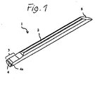
- a cutting tool T for boring which is an embodiment of a cutting tool of the present invention and is used with an insert 1 mounted in a holder 20.
- Fig. 1 is a perspective view of the insert 1.
- Fig. 2A is a top view of the insert 1 of Fig. 1
- Fig. 2B is a side view of the insert 1
- Fig. 2C is a front end view of the insert 1 as viewed from its front end which is an end portion where there is a cutting edge ridge
- Fig 2D is a front end view of the insert 1 according to an embodiment.
- Fig. 3A is a perspective view of a holder with an insert of Fig. 1 therein according to an embodiment of the present invention
- Fig. 3B is a side view of the cutting tool of Fig. 3A .
- the insert 1 is in the shape of a rod with a substantially circular transverse cross-section, and a shank portion 2 and a cutting edge portion 3 at an end portion continuous with the shank portion 2 are formed, and a corner 4a on the periphery side of a cutting edge ridge 4 in cutting edge portion protrudes toward the periphery of the rod-shapped insert 1.
- the holder 20 of elongated shape is provided with a long insertion hole 21, which allows insertion of the insert 1 from a front end of the holder 20, and the insertion hole 21 is provided with a positioning member 22, which comes into contact with an inclined surface 8 of the insert 1, therein.
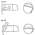
- FIGS. 4A and 4B are diagrams illustrating a flow of chips when a workpiece has cut with a negative radial rake angle and zero radial rake angle respectively. As is apparent from Figs. 4A and 4B , an arrow indicating a direction in which chips are produced is directed more toward the rear of the insert in the structure of Fig.
- Fig. 4A in which the cutting edge ridge 4 has a negative radial rake angle ⁇ as in the structure of Figs. 1 through 2D , than that in the structure of Fig. 4B in which the radial rake angle ⁇ of the cutting edge ridge 4 is zero. Therefore, Fig. 4A provides better chip evacuation performance.
- the radial rake angle ⁇ refers to an angle formed by a reference plane S, which is a straight line passing through a cutting point at which the corner 4a of the cutting edge ridge 4 contacts the workpiece and a center O of a circular machining cross-section (machining path), and a straight line L parallel to the cutting edge ridge 4 illustrated in Fig. 2C in the front end view of the insert 1.
- the negative radial rake angle ⁇ preferably ranges from 5° to 20° when chip processability and cutting resistance are taken into account.
- the negative radial rake angle ⁇ is 5° or greater, better chip processability is achieved, and if the negative radial rake angle ⁇ is 20° or less, the rake angle at the corner 4a is not too negative and thus the cutting resistance at the corner 4a is not too high.
- the machining path is circular as indicated by a dotted line in Fig. 2C , and corner 4a protruding on the periphery side of the cutting edge ridge 4 is set such that it is positioned immediately beside the machining path (a position which is at the same height as the center of the circular machining path). Therefore, in the front end view of the insert 1, the cutting edge ridge 4 is present above a semicircle of the insert 1 in transverse cross-section, that is, above the center of the insert.
- a first taper (first cut surface) 6 is preferably formed above the corner 4a protruding on the periphery side of the cutting edge ridge 4, that is, above the cutting edge ridge 4.
- the inclined surface 8 is formed at the end portion opposite that having the cutting edge portion 3.
- the insert 1 is inserted from the inclined surface 8 side into the insertion hole 21 of the holder 20, and secured such that the inclined surface 8 is in line contact with the positioning member 22 in the holder 20.
- This structure facilitates high-precision positioning of the cutting edge of the insert 1 in the longitudinal and rotational directions.
- a side surface of the holder 20 is provided with a plurality of positioning-member mounting holes 23 for insertion of the positioning member 22 having a rod-like shape.
- the rod-like positioning member 22 is inserted into one of the positioning-member mounting holes 23.
- the reason for providing the many positioning-member mounting holes 23 is to provide a structure that can appropriately adjust the overhang length of the insert 1.
- the positioning member 22 may be a pin, a screw member, or anything that comes into contact with the inclined surface 8 of the insert 1.
- the positioning member 22 may be a rod-like member in the shape of a cylinder or a polygonal prism such as a triangular prism, and is not limited thereto.
- a pin which can be easily inserted and removed, the overhang length of the insert 1 can be changed easily.
- a pin is used as the positioning member 22.
- the positioning member 22 is positioned such that an axis of the positioning member 22 is perpendicular to the longitudinal direction of the insertion hole 21.
- a method of securing the positioning member 22 may be securing method of sandwiching it between screws on both sides thereof, securing method of threading one end of the cylindrical pin and screwing this threaded part into a threaded part with which the holder 20 is provided, securing method of forming the cylindrical pin into a tapered shape having a greater diameter at one end and bringing the tapered part into contact with a predetermined portion in the positioning-member mounting hole 23, securing method of securing it with an adhesive, or securing method of fastening the side surface of the cylindrical pin with a screw member.
- Figs. 3A and 3B are securing method of sandwiching it between screws on both sides thereof, securing method of threading one end of the cylindrical pin and screwing this threaded part into a threaded part with which the holder 20 is provided, securing method of forming the cylindrical pin into a tapered shape having a greater diameter at one end and bringing the tapered part into contact with a predetermined portion in the positioning-member
- a securing method in which a cylindrical pin (positioning member 22) is inserted into the positioning-member mounting hole 23 located in the side surface of the holder 20, a screw hole 26 is formed in an upper surface of the holder 20, and the screw member 27 is fastened to this to be in contact with the positioning member 22.
- the position of the positioning member 22 in the insertion hole may be appropriately adjusted in accordance with the insertion angle of the inclined surface 8 of the insert 1.
- the inclined surface 8 of the insert 1 is brought into line contact with the positioning member 22.
- the positioning member 22 is a cylindrical pin and the insert 1 is mounted in the holder 20
- a direction perpendicular to the longitudinal direction of the inclined surface 8 is parallel to a direction of the periphery of the positioning member 22 perpendicular to the longitudinal, direction of the holder 20. This makes it possible to realize stable and firm restraint.
- the holder 20 is provided with not only the positioning member 22, but also screw holes 24 which is formed at a location closer to the front end (first end) side of the holder 20 than the positioning member 22 is, and which penetrates the holder 20 from the periphery thereof to the insertion hole 21, the screw members 25 are screwed into the respective screw holes 24, so that the periphery of the shank portion 2 of the insert 1 is pressed and secured by the front ends of the screw members 25.
- the periphery of the shank portion 2 contacted by the screw members 25 may be a curved surface.
- the insert 1 can be mounted with high positioning accuracy.
- the periphery of the shank portion 2 contacted by the screw members 25 is a flat surface, if the clearance of the screw members 25 screwed into the holder is 10 to 30', the flat end faces of the screw members 25 are brought into surface contact with the flat periphery of the shank and secured. When secured by surface contact, the screw members 25 provide a greater restraining force.
- an upper flat surface (second cut surface) 10 may be formed on the side opposite the corner 4a protruding on the periphery side of the cutting edge ridge 4 continuous with the first taper 6, that is, on the side opposite the cutting edge ridge 4 continuous with the first taper 6, so that the insert 1 may be positioned and secured by bringing the screw members 25 into contact with the upper flat surface 10.
- a lower flat surface 11 may be formed on the side opposite the upper flat surface 10, but the lower flat surface 11 does not necessarily have to be formed.
- Figs. 1 through 2D illustrate the structure where the second taper 7 extends rearward to the shank portion 2, the present invention is not limited to this, and a structure illustrated in Figs. 5 through 6C is also applicable. That is, in an insert 31 illustrated in Figs. 5 through 6C , a second taper 37 of a cutting edge portion 33 does not extend to a shank portion 32 in the rear, and as viewed from the front end of the insert 31, the shank portion 32 protrudes toward one end 34a of a cutting edge ridge 34 with respect to the cutting edge portion 33 (or from the second taper 37 in Figs. 6A to 6C ). In the structure of Fig.
- the shank portion 32 includes, corresponding to the insertion hole 21 of the holder 20, a curve extending from a point 40b to a point 40c and a curve including a point 40a and extending from a point 40d to the point 40e.
- the insert 31 is secured at three or more securing points included in the two curves and surrounding a center P of the insertion hole 21.
Description
- The present invention relates to a cutting tool used with an insert mounted in a holder according to the preamble of
claim 1. Such a cutting tool is e.g. known fromPatent Literature 1 referenced below. - As a cutting tool used for inside diameter boring or grooving, there has been conventionally known a cutting tool in which a rod-like insert having a cutting edge portion (hereinafter simply referred to as an insert) is inserted into a hole of a holder and secured by tightening bolts.
- For example,
Patent Literature 1 discloses that by inserting a rear end of a rod-like insert having a cutting edge portion at a front end thereof into a hole of a holder followed by adjusting the position of the cutting edge portion, the insert is prevented from being chipped off during mounting of the holder. Further,Patent Literature 2 discloses a cutting insert comprising a rake face region located on an upper surface, a flank located on a front surface, and a cutting edge located at an intersection between the rake face region and the flank. Patent Literature 3 discloses a rotating cutting tool having a body with reversible cutting inserts. -
- Patent Literature 1: Japanese Unexamined Patent Application Publication No.
2000-271805 - Patent Literature 2: United States Patent Application Publication
US2010/0067992A1 - Patent Literature 3: German Patent Application Publication
DE 2805670 - However, with the rod-like insert disclosed in
Patent Literature 1, chip evacuation performance tends to deteriorate as the machining diameter decreases. As a result, for example, the cutting edge portion is chipped off by biting chips during machining. - An object of the present invention is to provide a cutting tool that provides good chip evacuation performance.
- A cutting tool according to
claim 1 of the present invention includes an insert in the shape of a rod with a substantially circular transverse cross-section, the insert including a shank portion and a cutting edge portion at an end portion continuous with the shank portion, the cutting edge having a cutting edge ridge protruding at one end thereof toward the periphery of the rod; and a holder to which the insert is secured. When the insert is secured to the holder, the cutting edge ridge has a negative radial rake angle. Further embodiments are described in the dependent claims. - In the cutting tool according to the present invention, since chips are produced more toward the rear of the insert by the cutting edge ridge having a negative radial rake angle, chip evacuation performance of the cutting tool is improved.
-
-
Fig. 1 is a perspective view of an insert of an embodiment for use in a cutting tool according to the present invention. -
Fig. 2A is a top view of the insert ofFig. 1 . -
Fig. 2B is a side view of the insert ofFig 1 . -
Fig. 2C is a front end view of the insert ofFig 1 . -
Fig 2D is a front end view of the insert according to an embodiment of the present invention. -
Fig. 3A is a perspective view of a holder with an insert ofFig. 1 therein according to an embodiment of the present invention. -
Fig. 3B is a side view of the cutting tool ofFig 3A . -
Fig. 4A is a diagram illustrating a flow of chips when a workpiece is cut with the cutting tool having a negative radial rake angle according to an embodiment of the present invention. -
Fig. 4B is a diagram illustrating a flow of chips when a workpiece is cut with the cutting tool having a radial rake angle equal to zero. -
Fig. 5 is a perspective view of the insert of another embodiment for use in the cutting tool according to the present invention. -
Fig. 6A is a top view of the insert ofFig. 5 . -
Fig 6B is a side view of the insert ofFig 5 . -
Fig 6C is a front end view of the insert ofFig. 5 . -
Fig. 7 is a front end view of an embodiment of a conventional insert. - With reference to
Figs. 1 to 3B , a cutting tool T for boring will be described, which is an embodiment of a cutting tool of the present invention and is used with aninsert 1 mounted in aholder 20.Fig. 1 is a perspective view of theinsert 1.Fig. 2A is a top view of theinsert 1 ofFig. 1 ,Fig. 2B is a side view of theinsert 1,Fig. 2C is a front end view of theinsert 1 as viewed from its front end which is an end portion where there is a cutting edge ridge, andFig 2D is a front end view of theinsert 1 according to an embodiment.Fig. 3A is a perspective view of a holder with an insert ofFig. 1 therein according to an embodiment of the present invention andFig. 3B is a side view of the cutting tool ofFig. 3A . - Referring to
Fig. 1 , theinsert 1 is in the shape of a rod with a substantially circular transverse cross-section, and ashank portion 2 and a cutting edge portion 3 at an end portion continuous with theshank portion 2 are formed, and acorner 4a on the periphery side of a cutting edge ridge 4 in cutting edge portion protrudes toward the periphery of the rod-shappedinsert 1. - As illustrated in
Figs. 3A and 3B , on the other hand, theholder 20 of elongated shape is provided with a long insertion hole 21, which allows insertion of theinsert 1 from a front end of theholder 20, and the insertion hole 21 is provided with a positioning member 22, which comes into contact with an inclined surface 8 of theinsert 1, therein. - Referring to
Figs. 1 through 2D when theinsert 1 is inserted into the insertion hole 21 of theholder 20 from an end opposite the end portion having the cutting edge portion 3 and is secured to theholder 20, the cutting edge ridge 4 has a negative radial rake angle α as illustrated inFig. 2C Figs. 4A and 4B are diagrams illustrating a flow of chips when a workpiece has cut with a negative radial rake angle and zero radial rake angle respectively. As is apparent fromFigs. 4A and 4B , an arrow indicating a direction in which chips are produced is directed more toward the rear of the insert in the structure ofFig. 4A , in which the cutting edge ridge 4 has a negative radial rake angle α as in the structure ofFigs. 1 through 2D , than that in the structure ofFig. 4B in which the radial rake angle α of the cutting edge ridge 4 is zero. Therefore,Fig. 4A provides better chip evacuation performance. - Note that the radial rake angle α refers to an angle formed by a reference plane S, which is a straight line passing through a cutting point at which the
corner 4a of the cutting edge ridge 4 contacts the workpiece and a center O of a circular machining cross-section (machining path), and a straight line L parallel to the cutting edge ridge 4 illustrated inFig. 2C in the front end view of theinsert 1. The negative radial rake angle α preferably ranges from 5° to 20° when chip processability and cutting resistance are taken into account. That is, if the negative radial rake angle α is 5° or greater, better chip processability is achieved, and if the negative radial rake angle α is 20° or less, the rake angle at thecorner 4a is not too negative and thus the cutting resistance at thecorner 4a is not too high. - In a cutting operation using the
insert 1, the machining path is circular as indicated by a dotted line inFig. 2C , andcorner 4a protruding on the periphery side of the cutting edge ridge 4 is set such that it is positioned immediately beside the machining path (a position which is at the same height as the center of the circular machining path). Therefore, in the front end view of theinsert 1, the cutting edge ridge 4 is present above a semicircle of theinsert 1 in transverse cross-section, that is, above the center of the insert. Thus, it is possible to improve rigidity of the cutting edge portion 3 of theinsert 1, reduce deflection of theinsert 1 during cutting, and reduce chattering of theinsert 1, - In the front end view of the
insert 1, a first taper (first cut surface) 6 is preferably formed above thecorner 4a protruding on the periphery side of the cutting edge ridge 4, that is, above the cutting edge ridge 4. When the first taper 6 is elongated to the rear of theinsert 1 having a rod-like shape, the overhang length of theinsert 1 can be changed freely. - In the front end view of the
insert 1, there is only a second taper (side relief surface) 7 below thecorner 4a of the cutting edge ridge 4, and no taper other than the second taper is present below thecorner 4a. Conventionally, as illustrated inFig. 7 , it has been necessary to form alower cut surface 30 in addition to thesecond taper 7, but the cutting edge portion 3 does not require thecut surface 30 with the structure illustrated inFigs. 1 and2 , because it is possible to reduce interference of the lower part of the cutting edge portion 3 below the cutting edge ridge 4 with the workpiece. This eliminates the step of machining thelower cut surface 30 and reduces the cost. In the structure illustrated inFigs. 1 and2 , thesecond taper 7 extends rearward to theshank portion 2. - Furthermore, as illustrated in
Figs. 3A and 3B ., the inclined surface 8 is formed at the end portion opposite that having the cutting edge portion 3. Theinsert 1 is inserted from the inclined surface 8 side into the insertion hole 21 of theholder 20, and secured such that the inclined surface 8 is in line contact with the positioning member 22 in theholder 20. This structure facilitates high-precision positioning of the cutting edge of theinsert 1 in the longitudinal and rotational directions. - In
Figs. 3A and 3B , a side surface of theholder 20 is provided with a plurality of positioning-member mounting holes 23 for insertion of the positioning member 22 having a rod-like shape. The rod-like positioning member 22 is inserted into one of the positioning-member mounting holes 23. The reason for providing the many positioning-member mounting holes 23 is to provide a structure that can appropriately adjust the overhang length of theinsert 1. The positioning member 22 may be a pin, a screw member, or anything that comes into contact with the inclined surface 8 of theinsert 1. For example, the positioning member 22 may be a rod-like member in the shape of a cylinder or a polygonal prism such as a triangular prism, and is not limited thereto. With a pin, which can be easily inserted and removed, the overhang length of theinsert 1 can be changed easily. In the present embodiment, a pin is used as the positioning member 22. The positioning member 22 is positioned such that an axis of the positioning member 22 is perpendicular to the longitudinal direction of the insertion hole 21. - A method of securing the positioning member 22 may be securing method of sandwiching it between screws on both sides thereof, securing method of threading one end of the cylindrical pin and screwing this threaded part into a threaded part with which the
holder 20 is provided, securing method of forming the cylindrical pin into a tapered shape having a greater diameter at one end and bringing the tapered part into contact with a predetermined portion in the positioning-member mounting hole 23, securing method of securing it with an adhesive, or securing method of fastening the side surface of the cylindrical pin with a screw member. InFigs. 3A and 3B . adopted is a securing method in which a cylindrical pin (positioning member 22) is inserted into the positioning-member mounting hole 23 located in the side surface of theholder 20, ascrew hole 26 is formed in an upper surface of theholder 20, and the screw member 27 is fastened to this to be in contact with the positioning member 22. - The position of the positioning member 22 in the insertion hole may be appropriately adjusted in accordance with the insertion angle of the inclined surface 8 of the
insert 1. The inclined surface 8 of theinsert 1 is brought into line contact with the positioning member 22. For example, when the positioning member 22 is a cylindrical pin and theinsert 1 is mounted in theholder 20, a direction perpendicular to the longitudinal direction of the inclined surface 8 is parallel to a direction of the periphery of the positioning member 22 perpendicular to the longitudinal, direction of theholder 20. This makes it possible to realize stable and firm restraint. - Referring to
Figs. 3A and 3B , to reduce falling and looseness of theinsert 1, theholder 20 is provided with not only the positioning member 22, but also screw holes 24 which is formed at a location closer to the front end (first end) side of theholder 20 than the positioning member 22 is, and which penetrates theholder 20 from the periphery thereof to the insertion hole 21, thescrew members 25 are screwed into the respective screw holes 24, so that the periphery of theshank portion 2 of theinsert 1 is pressed and secured by the front ends of thescrew members 25. The periphery of theshank portion 2 contacted by thescrew members 25 may be a curved surface. That is, when theshank portion 2 is contacted on its curved surface by thescrew members 25, since theinsert 1 is not rotated during mounting by the effect of variations in manufacture, theinsert 1 can be mounted with high positioning accuracy. Alternatively, when the periphery of theshank portion 2 contacted by thescrew members 25 is a flat surface, if the clearance of thescrew members 25 screwed into the holder is 10 to 30', the flat end faces of thescrew members 25 are brought into surface contact with the flat periphery of the shank and secured. When secured by surface contact, thescrew members 25 provide a greater restraining force. - Although the structure for positioning the
insert 1 using the inclined surface 8 has been described withFigs. 1 and2 , the present invention is not limited to this, and, as illustrated inFig. 2D of a front end view of another embodiment of the cutting tool of the present invention, an upper flat surface (second cut surface) 10 may be formed on the side opposite thecorner 4a protruding on the periphery side of the cutting edge ridge 4 continuous with the first taper 6, that is, on the side opposite the cutting edge ridge 4 continuous with the first taper 6, so that theinsert 1 may be positioned and secured by bringing thescrew members 25 into contact with the upperflat surface 10. In this case, a lowerflat surface 11 may be formed on the side opposite the upperflat surface 10, but the lowerflat surface 11 does not necessarily have to be formed. - Although
Figs. 1 through 2D illustrate the structure where thesecond taper 7 extends rearward to theshank portion 2, the present invention is not limited to this, and a structure illustrated inFigs. 5 through 6C is also applicable. That is, in aninsert 31 illustrated inFigs. 5 through 6C , a second taper 37 of acutting edge portion 33 does not extend to ashank portion 32 in the rear, and as viewed from the front end of theinsert 31, theshank portion 32 protrudes toward oneend 34a of acutting edge ridge 34 with respect to the cutting edge portion 33 (or from the second taper 37 inFigs. 6A to 6C ). In the structure ofFig. 6 , theshank portion 32 includes, corresponding to the insertion hole 21 of theholder 20, a curve extending from a point 40b to a point 40c and a curve including a point 40a and extending from a point 40d to the point 40e. Theinsert 31 is secured at three or more securing points included in the two curves and surrounding a center P of the insertion hole 21. Thus, when theshank portion 32 of theinsert 31 is inserted into the insertion hole 21 of theholder 20, theinsert 31 is prevented from loosening or deflecting, and it is possible to reduce twisting of theinsert 31 and the resulting change in position of the cuttingedge ridge 34. -
- 1, 31: insert
- 2, 32: shank portion
- 3, 33: cutting edge portion
- 4, 34: cutting edge ridge
- 4a, 34a: corner
- 6: first taper (first cut surface)
- 7, 37: second taper (side relief surface)
- 8: inclined surface
- 10: upper flat surface (second cut surface)
- 11: second taper (third cut surface)
- 20: holder
- 21: insertion hole
- 22: positioning member
- 23: positioning-member mounting hole
- 24, 26: screw hole
- 25, 27: screw member
- 30: lower cut surface
- 40 (40a to 40e): point
- T: cutting tool
- α: radial rake angle
- S: reference plane (a straight line passing through the cutting point at which the corner of the cutting edge ridge contacts the workpiece and a center of the circular machining cross-section (machining path))
- L: straight line parallel to cutting edge ridge
Claims (9)
- A cutting tool comprising:an insert (1) having a rod shape with a substantially circular transverse cross-section, the insert (1) comprising:a shank portion (2); anda cutting edge portion (3),which is formed at an end portion continuous with the shank portion (2), and in which one end of a cutting edge ridge (4) protrudes toward a periphery of the insert (1); anda holder (20) to which the insert (1) is secured; characterized in that,when the insert (1) is secured to the holder (20), the cutting edge ridge (4) has a negative radial rake angle (α).
- The cutting tool according to claim 1, wherein as viewed from the end portion of the insert (1), a tip ridge extending continuously from the cutting edge ridge (4) is located above a center of the insert (1).
- The cutting tool according to claim 1 or 2, wherein in the shank portion (2), as viewed from the end portion of the insert (1), there is a first taper (6) above the cutting edge ridge (4).
- The cutting tool according to claim 3, wherein in the shank portion (2), as viewed from the end portion of the insert (1), an upper flat surface is formed on a side opposite the cutting edge ridge (4) continuous with the first taper (6).
- The cutting tool according to any one of claims 1 to 4, wherein as viewed from the end portion of the insert (1), there is a second taper (7) below the cutting edge ridge (4), and no taper other than the second taper (7) is present below the cutting edge ridge (4).
- The cutting tool according to any one of claims 1 to 5, wherein
an insertion hole (21) is in the holder (20), and the shank portion (2) of the insert (1) is inserted in the insertion hole (21);
an inclined surface (8) is at an end portion opposite the end portion at which the cutting edge portion (3) of the insert (1) is formed; and
the cutting tool comprises a positioning member in line contact with the inclined surface (8). - The cutting tool according to any one of claims 1 to 6, wherein the radial rake angle (α) ranges from 5° to 20°.
- The cutting tool according to any one of claims 1 to 7, wherein the shank portion (2) of the insert (1) is secured in an insertion hole (21) of the holder (20) at three or more securing points surrounding a center of the insertion hole (21).
- The cutting tool according to claim 8, wherein as viewed from the end portion of the insert (1), the shank portion (2) of the insert (1) has a shape which protrudes from the cutting edge portion (3) toward the one end of the cutting edge ridge (4).
Applications Claiming Priority (2)
| Application Number | Priority Date | Filing Date | Title |
|---|---|---|---|
| JP2011029822 | 2011-02-15 | ||
| PCT/JP2012/053541 WO2012111710A1 (en) | 2011-02-15 | 2012-02-15 | Cutting tool |
Publications (3)
| Publication Number | Publication Date |
|---|---|
| EP2676751A1 EP2676751A1 (en) | 2013-12-25 |
| EP2676751A4 EP2676751A4 (en) | 2014-12-17 |
| EP2676751B1 true EP2676751B1 (en) | 2016-08-10 |
Family
ID=46672623
Family Applications (1)
| Application Number | Title | Priority Date | Filing Date |
|---|---|---|---|
| EP12746480.8A Active EP2676751B1 (en) | 2011-02-15 | 2012-02-15 | Cutting tool |
Country Status (5)
| Country | Link |
|---|---|
| US (1) | US9764389B2 (en) |
| EP (1) | EP2676751B1 (en) |
| JP (1) | JP5701321B2 (en) |
| CN (1) | CN103298576B (en) |
| WO (1) | WO2012111710A1 (en) |
Families Citing this family (6)
| Publication number | Priority date | Publication date | Assignee | Title |
|---|---|---|---|---|
| EP2821168A1 (en) * | 2013-07-04 | 2015-01-07 | Applitec Moutier S.A. | System for internal machining |
| CN104816001B (en) * | 2015-04-17 | 2017-06-16 | 郑锡添 | Aperture working of plastics boring cutter |
| DE102015112049B3 (en) * | 2015-07-23 | 2016-09-22 | Stoba Sondermaschinen Gmbh | Collet system with positioning |
| US11052473B2 (en) * | 2017-04-12 | 2021-07-06 | Stojan Stojanovski | Cutting tool assembly |
| AT522997B1 (en) * | 2019-10-09 | 2021-11-15 | Diametal A G | Turning tool with tool changer |
| USD956222S1 (en) | 2020-08-21 | 2022-06-28 | Stryker European Operations Limited | Surgical bur assembly |
Family Cites Families (16)
| Publication number | Priority date | Publication date | Assignee | Title |
|---|---|---|---|---|
| NL298134A (en) * | 1962-09-27 | |||
| SE419834B (en) * | 1977-02-11 | 1981-08-31 | Seco Tools Ab | TROUBLESHOOTING AND TOOLS FOR CORN MILLING |
| DE2713529A1 (en) * | 1977-03-26 | 1978-09-28 | Ewald Granacher | Lathe or boring machine boring tool - has elliptical section shank with cutting edge on line joining curve centres |
| JPS62117003U (en) * | 1986-01-13 | 1987-07-25 | ||
| US5332339A (en) * | 1991-06-19 | 1994-07-26 | Mitsubishi Materials Corporation | Throw-away cutting tool |
| US5848862A (en) * | 1997-06-24 | 1998-12-15 | Antoun; Gregory S. | Boring bar with reverse mounted insert |
| JP2000271805A (en) * | 1999-03-19 | 2000-10-03 | Mitsubishi Materials Corp | Hole machining tool |
| JP2004216495A (en) * | 2003-01-14 | 2004-08-05 | Mitsubishi Materials Corp | Tool holder |
| DE102004053511B4 (en) * | 2003-10-30 | 2011-06-09 | Kyocera Corporation | cutting tool |
| IL159188A (en) * | 2003-12-04 | 2008-08-07 | Uzi Gati | Cutting insert for grooving operations |
| CN101528391B (en) * | 2006-10-31 | 2010-12-01 | 京瓷株式会社 | Cutting insert |
| DE112008002261B4 (en) * | 2007-08-31 | 2015-06-25 | Kyocera Corporation | Cutting insert, cutting tool and cutting method |
| EP2305406B1 (en) * | 2008-06-27 | 2017-04-19 | Kyocera Corporation | Cutting tool and cutting method using same |
| JP2009034819A (en) * | 2008-11-17 | 2009-02-19 | Kyocera Corp | Cutting tool |
| EP2450135B1 (en) * | 2009-06-29 | 2019-05-01 | Kyocera Corporation | Cutting tool with insert and holder |
| CN101912987B (en) | 2010-08-31 | 2012-01-18 | 株洲钻石切削刀具股份有限公司 | Drill bit for processing deep hole with large length-diameter ratio |
-
2012
- 2012-02-15 US US13/985,846 patent/US9764389B2/en active Active
- 2012-02-15 CN CN201280004705.XA patent/CN103298576B/en active Active
- 2012-02-15 WO PCT/JP2012/053541 patent/WO2012111710A1/en active Application Filing
- 2012-02-15 EP EP12746480.8A patent/EP2676751B1/en active Active
- 2012-02-15 JP JP2012557995A patent/JP5701321B2/en active Active
Also Published As
| Publication number | Publication date |
|---|---|
| US20140161549A1 (en) | 2014-06-12 |
| US9764389B2 (en) | 2017-09-19 |
| EP2676751A1 (en) | 2013-12-25 |
| CN103298576B (en) | 2015-10-14 |
| WO2012111710A1 (en) | 2012-08-23 |
| JP5701321B2 (en) | 2015-04-15 |
| EP2676751A4 (en) | 2014-12-17 |
| CN103298576A (en) | 2013-09-11 |
| JPWO2012111710A1 (en) | 2014-07-07 |
Similar Documents
| Publication | Publication Date | Title |
|---|---|---|
| EP2676751B1 (en) | Cutting tool | |
| EP1986808B1 (en) | Cutting tool and method of assembling a cutting tool | |
| EP1526293B1 (en) | Pair of threaded members | |
| JP4712124B2 (en) | Insert and holder and cutting tool using them | |
| JP2006272503A (en) | Insert removal type drill | |
| KR20070078787A (en) | Insert type cutting instrument and insert, method for attaching insert to insert to insert main body | |
| US5709510A (en) | Tool holder for inserts | |
| JP2018140482A (en) | Polygon processing tool | |
| US20060251493A1 (en) | Screw with a double thread and a recess in the side of the shank | |
| WO2013031457A1 (en) | Holder and cutting tool | |
| JPWO2019073716A1 (en) | cartridge | |
| US6679657B2 (en) | Tool for bore diameter work | |
| US6231274B1 (en) | End mill | |
| US7806633B2 (en) | Cutting insert with threaded hole and cutting tool therefor | |
| JP2008213077A (en) | Cutting insert and insert attachable and detachable type cutting tool | |
| JP2013071214A (en) | Cutting tool | |
| JP2017177307A (en) | Cutting insert and cutting tool | |
| JP5882822B2 (en) | Fixed member and cutting tool | |
| JP2020163524A (en) | Edge replaceable cutting tool, cutting insert and tool body | |
| JP2012111006A (en) | Cutting tool | |
| JP3151632U (en) | Holder for boring bar | |
| JPS5839603B2 (en) | drilling tool | |
| JP2009125842A (en) | Cutting tool | |
| JP5693142B2 (en) | Cutting tools | |
| WO2023223308A1 (en) | Tool holder having a cylindrical fixation bore extending rearwardly from a front fixation surface and a fastening bore intersecting the front fixation surface |
Legal Events
| Date | Code | Title | Description |
|---|---|---|---|
| PUAI | Public reference made under article 153(3) epc to a published international application that has entered the european phase |
Free format text: ORIGINAL CODE: 0009012 |
|
| 17P | Request for examination filed |
Effective date: 20130911 |
|
| AK | Designated contracting states |
Kind code of ref document: A1 Designated state(s): AL AT BE BG CH CY CZ DE DK EE ES FI FR GB GR HR HU IE IS IT LI LT LU LV MC MK MT NL NO PL PT RO RS SE SI SK SM TR |
|
| DAX | Request for extension of the european patent (deleted) | ||
| A4 | Supplementary search report drawn up and despatched |
Effective date: 20141114 |
|
| RIC1 | Information provided on ipc code assigned before grant |
Ipc: B23B 27/00 20060101AFI20141110BHEP Ipc: B23B 27/14 20060101ALI20141110BHEP |
|
| GRAP | Despatch of communication of intention to grant a patent |
Free format text: ORIGINAL CODE: EPIDOSNIGR1 |
|
| INTG | Intention to grant announced |
Effective date: 20160302 |
|
| GRAS | Grant fee paid |
Free format text: ORIGINAL CODE: EPIDOSNIGR3 |
|
| GRAA | (expected) grant |
Free format text: ORIGINAL CODE: 0009210 |
|
| AK | Designated contracting states |
Kind code of ref document: B1 Designated state(s): AL AT BE BG CH CY CZ DE DK EE ES FI FR GB GR HR HU IE IS IT LI LT LU LV MC MK MT NL NO PL PT RO RS SE SI SK SM TR |
|
| REG | Reference to a national code |
Ref country code: GB Ref legal event code: FG4D |
|
| REG | Reference to a national code |
Ref country code: CH Ref legal event code: EP Ref country code: AT Ref legal event code: REF Ref document number: 818522 Country of ref document: AT Kind code of ref document: T Effective date: 20160815 |
|
| REG | Reference to a national code |
Ref country code: IE Ref legal event code: FG4D |
|
| REG | Reference to a national code |
Ref country code: DE Ref legal event code: R096 Ref document number: 602012021514 Country of ref document: DE |
|
| REG | Reference to a national code |
Ref country code: LT Ref legal event code: MG4D |
|
| REG | Reference to a national code |
Ref country code: NL Ref legal event code: MP Effective date: 20160810 |
|
| REG | Reference to a national code |
Ref country code: AT Ref legal event code: MK05 Ref document number: 818522 Country of ref document: AT Kind code of ref document: T Effective date: 20160810 |
|
| PG25 | Lapsed in a contracting state [announced via postgrant information from national office to epo] |
Ref country code: HR Free format text: LAPSE BECAUSE OF FAILURE TO SUBMIT A TRANSLATION OF THE DESCRIPTION OR TO PAY THE FEE WITHIN THE PRESCRIBED TIME-LIMIT Effective date: 20160810 Ref country code: FI Free format text: LAPSE BECAUSE OF FAILURE TO SUBMIT A TRANSLATION OF THE DESCRIPTION OR TO PAY THE FEE WITHIN THE PRESCRIBED TIME-LIMIT Effective date: 20160810 Ref country code: RS Free format text: LAPSE BECAUSE OF FAILURE TO SUBMIT A TRANSLATION OF THE DESCRIPTION OR TO PAY THE FEE WITHIN THE PRESCRIBED TIME-LIMIT Effective date: 20160810 Ref country code: NL Free format text: LAPSE BECAUSE OF FAILURE TO SUBMIT A TRANSLATION OF THE DESCRIPTION OR TO PAY THE FEE WITHIN THE PRESCRIBED TIME-LIMIT Effective date: 20160810 Ref country code: IS Free format text: LAPSE BECAUSE OF FAILURE TO SUBMIT A TRANSLATION OF THE DESCRIPTION OR TO PAY THE FEE WITHIN THE PRESCRIBED TIME-LIMIT Effective date: 20161210 Ref country code: NO Free format text: LAPSE BECAUSE OF FAILURE TO SUBMIT A TRANSLATION OF THE DESCRIPTION OR TO PAY THE FEE WITHIN THE PRESCRIBED TIME-LIMIT Effective date: 20161110 Ref country code: IT Free format text: LAPSE BECAUSE OF FAILURE TO SUBMIT A TRANSLATION OF THE DESCRIPTION OR TO PAY THE FEE WITHIN THE PRESCRIBED TIME-LIMIT Effective date: 20160810 Ref country code: LT Free format text: LAPSE BECAUSE OF FAILURE TO SUBMIT A TRANSLATION OF THE DESCRIPTION OR TO PAY THE FEE WITHIN THE PRESCRIBED TIME-LIMIT Effective date: 20160810 |
|
| PG25 | Lapsed in a contracting state [announced via postgrant information from national office to epo] |
Ref country code: ES Free format text: LAPSE BECAUSE OF FAILURE TO SUBMIT A TRANSLATION OF THE DESCRIPTION OR TO PAY THE FEE WITHIN THE PRESCRIBED TIME-LIMIT Effective date: 20160810 Ref country code: LV Free format text: LAPSE BECAUSE OF FAILURE TO SUBMIT A TRANSLATION OF THE DESCRIPTION OR TO PAY THE FEE WITHIN THE PRESCRIBED TIME-LIMIT Effective date: 20160810 Ref country code: PT Free format text: LAPSE BECAUSE OF FAILURE TO SUBMIT A TRANSLATION OF THE DESCRIPTION OR TO PAY THE FEE WITHIN THE PRESCRIBED TIME-LIMIT Effective date: 20161212 Ref country code: AT Free format text: LAPSE BECAUSE OF FAILURE TO SUBMIT A TRANSLATION OF THE DESCRIPTION OR TO PAY THE FEE WITHIN THE PRESCRIBED TIME-LIMIT Effective date: 20160810 Ref country code: SE Free format text: LAPSE BECAUSE OF FAILURE TO SUBMIT A TRANSLATION OF THE DESCRIPTION OR TO PAY THE FEE WITHIN THE PRESCRIBED TIME-LIMIT Effective date: 20160810 Ref country code: PL Free format text: LAPSE BECAUSE OF FAILURE TO SUBMIT A TRANSLATION OF THE DESCRIPTION OR TO PAY THE FEE WITHIN THE PRESCRIBED TIME-LIMIT Effective date: 20160810 Ref country code: GR Free format text: LAPSE BECAUSE OF FAILURE TO SUBMIT A TRANSLATION OF THE DESCRIPTION OR TO PAY THE FEE WITHIN THE PRESCRIBED TIME-LIMIT Effective date: 20161111 |
|
| PG25 | Lapsed in a contracting state [announced via postgrant information from national office to epo] |
Ref country code: EE Free format text: LAPSE BECAUSE OF FAILURE TO SUBMIT A TRANSLATION OF THE DESCRIPTION OR TO PAY THE FEE WITHIN THE PRESCRIBED TIME-LIMIT Effective date: 20160810 Ref country code: RO Free format text: LAPSE BECAUSE OF FAILURE TO SUBMIT A TRANSLATION OF THE DESCRIPTION OR TO PAY THE FEE WITHIN THE PRESCRIBED TIME-LIMIT Effective date: 20160810 |
|
| REG | Reference to a national code |
Ref country code: DE Ref legal event code: R097 Ref document number: 602012021514 Country of ref document: DE |
|
| PG25 | Lapsed in a contracting state [announced via postgrant information from national office to epo] |
Ref country code: DK Free format text: LAPSE BECAUSE OF FAILURE TO SUBMIT A TRANSLATION OF THE DESCRIPTION OR TO PAY THE FEE WITHIN THE PRESCRIBED TIME-LIMIT Effective date: 20160810 Ref country code: BE Free format text: LAPSE BECAUSE OF FAILURE TO SUBMIT A TRANSLATION OF THE DESCRIPTION OR TO PAY THE FEE WITHIN THE PRESCRIBED TIME-LIMIT Effective date: 20160810 Ref country code: SK Free format text: LAPSE BECAUSE OF FAILURE TO SUBMIT A TRANSLATION OF THE DESCRIPTION OR TO PAY THE FEE WITHIN THE PRESCRIBED TIME-LIMIT Effective date: 20160810 Ref country code: CZ Free format text: LAPSE BECAUSE OF FAILURE TO SUBMIT A TRANSLATION OF THE DESCRIPTION OR TO PAY THE FEE WITHIN THE PRESCRIBED TIME-LIMIT Effective date: 20160810 Ref country code: SM Free format text: LAPSE BECAUSE OF FAILURE TO SUBMIT A TRANSLATION OF THE DESCRIPTION OR TO PAY THE FEE WITHIN THE PRESCRIBED TIME-LIMIT Effective date: 20160810 Ref country code: BG Free format text: LAPSE BECAUSE OF FAILURE TO SUBMIT A TRANSLATION OF THE DESCRIPTION OR TO PAY THE FEE WITHIN THE PRESCRIBED TIME-LIMIT Effective date: 20161110 |
|
| PLBE | No opposition filed within time limit |
Free format text: ORIGINAL CODE: 0009261 |
|
| STAA | Information on the status of an ep patent application or granted ep patent |
Free format text: STATUS: NO OPPOSITION FILED WITHIN TIME LIMIT |
|
| 26N | No opposition filed |
Effective date: 20170511 |
|
| PG25 | Lapsed in a contracting state [announced via postgrant information from national office to epo] |
Ref country code: SI Free format text: LAPSE BECAUSE OF FAILURE TO SUBMIT A TRANSLATION OF THE DESCRIPTION OR TO PAY THE FEE WITHIN THE PRESCRIBED TIME-LIMIT Effective date: 20160810 |
|
| PG25 | Lapsed in a contracting state [announced via postgrant information from national office to epo] |
Ref country code: MC Free format text: LAPSE BECAUSE OF FAILURE TO SUBMIT A TRANSLATION OF THE DESCRIPTION OR TO PAY THE FEE WITHIN THE PRESCRIBED TIME-LIMIT Effective date: 20160810 |
|
| REG | Reference to a national code |
Ref country code: CH Ref legal event code: PL |
|
| GBPC | Gb: european patent ceased through non-payment of renewal fee |
Effective date: 20170215 |
|
| PG25 | Lapsed in a contracting state [announced via postgrant information from national office to epo] |
Ref country code: CH Free format text: LAPSE BECAUSE OF NON-PAYMENT OF DUE FEES Effective date: 20170228 Ref country code: LI Free format text: LAPSE BECAUSE OF NON-PAYMENT OF DUE FEES Effective date: 20170228 |
|
| REG | Reference to a national code |
Ref country code: IE Ref legal event code: MM4A |
|
| REG | Reference to a national code |
Ref country code: FR Ref legal event code: ST Effective date: 20171031 |
|
| PG25 | Lapsed in a contracting state [announced via postgrant information from national office to epo] |
Ref country code: LU Free format text: LAPSE BECAUSE OF NON-PAYMENT OF DUE FEES Effective date: 20170215 |
|
| PG25 | Lapsed in a contracting state [announced via postgrant information from national office to epo] |
Ref country code: FR Free format text: LAPSE BECAUSE OF NON-PAYMENT OF DUE FEES Effective date: 20170228 |
|
| PG25 | Lapsed in a contracting state [announced via postgrant information from national office to epo] |
Ref country code: GB Free format text: LAPSE BECAUSE OF NON-PAYMENT OF DUE FEES Effective date: 20170215 Ref country code: IE Free format text: LAPSE BECAUSE OF NON-PAYMENT OF DUE FEES Effective date: 20170215 |
|
| PG25 | Lapsed in a contracting state [announced via postgrant information from national office to epo] |
Ref country code: MT Free format text: LAPSE BECAUSE OF NON-PAYMENT OF DUE FEES Effective date: 20170215 |
|
| PG25 | Lapsed in a contracting state [announced via postgrant information from national office to epo] |
Ref country code: AL Free format text: LAPSE BECAUSE OF FAILURE TO SUBMIT A TRANSLATION OF THE DESCRIPTION OR TO PAY THE FEE WITHIN THE PRESCRIBED TIME-LIMIT Effective date: 20160810 |
|
| PG25 | Lapsed in a contracting state [announced via postgrant information from national office to epo] |
Ref country code: HU Free format text: LAPSE BECAUSE OF FAILURE TO SUBMIT A TRANSLATION OF THE DESCRIPTION OR TO PAY THE FEE WITHIN THE PRESCRIBED TIME-LIMIT; INVALID AB INITIO Effective date: 20120215 |
|
| PG25 | Lapsed in a contracting state [announced via postgrant information from national office to epo] |
Ref country code: CY Free format text: LAPSE BECAUSE OF NON-PAYMENT OF DUE FEES Effective date: 20160810 |
|
| PG25 | Lapsed in a contracting state [announced via postgrant information from national office to epo] |
Ref country code: MK Free format text: LAPSE BECAUSE OF FAILURE TO SUBMIT A TRANSLATION OF THE DESCRIPTION OR TO PAY THE FEE WITHIN THE PRESCRIBED TIME-LIMIT Effective date: 20160810 |
|
| PG25 | Lapsed in a contracting state [announced via postgrant information from national office to epo] |
Ref country code: TR Free format text: LAPSE BECAUSE OF FAILURE TO SUBMIT A TRANSLATION OF THE DESCRIPTION OR TO PAY THE FEE WITHIN THE PRESCRIBED TIME-LIMIT Effective date: 20160810 |
|
| PGFP | Annual fee paid to national office [announced via postgrant information from national office to epo] |
Ref country code: DE Payment date: 20221229 Year of fee payment: 12 |
|
| P01 | Opt-out of the competence of the unified patent court (upc) registered |
Effective date: 20230508 |