JP2017177307A - Cutting insert and cutting tool - Google Patents
Cutting insert and cutting tool Download PDFInfo
- Publication number
- JP2017177307A JP2017177307A JP2016071428A JP2016071428A JP2017177307A JP 2017177307 A JP2017177307 A JP 2017177307A JP 2016071428 A JP2016071428 A JP 2016071428A JP 2016071428 A JP2016071428 A JP 2016071428A JP 2017177307 A JP2017177307 A JP 2017177307A
- Authority
- JP
- Japan
- Prior art keywords
- cutting
- cutting insert
- plate
- cutting edge
- outer peripheral
- Prior art date
- Legal status (The legal status is an assumption and is not a legal conclusion. Google has not performed a legal analysis and makes no representation as to the accuracy of the status listed.)
- Pending
Links
Images


Abstract
Description
本発明は、旋削加工のうち、溝入れ加工や突っ切り加工等に使用される切削インサートであって、とくに深い溝入れ加工に適した切削インサート、及びこれをホルダの先端部にクランプしてなる切削工具に関する。 The present invention is a cutting insert used for grooving, parting off, etc. in turning, and particularly a cutting insert suitable for deep grooving, and a cutting formed by clamping this to the tip of a holder. Related to tools.
旋削において所定幅の溝を設ける溝入れ加工用の切削インサート(バイト用インサート、又はスローアウェイチップともいわれる)の代表的なものに、矩形棒状又は薄板状の切削インサートであって、その切削インサート本体の一端に所定の刃幅の前切れ刃を有する、いわゆる1コーナ(1切れ刃)タイプのものがある(特許文献1参照)。このものでは、前後に直線状をなす下面(すくい面と反対の底面)に対し、上面(すくい面と同向き面)が、前切れ刃寄り位置で平行な被押圧部をなし、これから離間する基端側(前切れ刃と反対側)にいくにしたがいその下面に接近するようなガイド部を有している。このような切削インサート(以下、インサートともいう)が取付けられるホルダの先端部のチップ取付座は、インサートの下面に対向してそれと同様、前後に直線状に延びる着座部として形成され、これに対向するクランプ面のうち、インサートの前切れ刃寄り部位がその上面と平行な押圧部とされ、基端側に行くに従いガイド部に倣い着座部に近接するように形成されている。このような切削インサートは、そのクランプにおいては、これをその取付座に前方から押し込み、その着座部に切削インサートにおける底面(下面)を着座させることでクランプされる。すなわち、このようにして着座させることで、その反対側(すくい面側)の前切れ刃寄り部位を、ホルダに一体で設けられているクランプ部位の押圧部で、それ自体の適度の弾性変形を利用して、上下間で締め付けるようにする、いわゆる自己拘束形式によるクランプとされている。また、このような1コーナタイプのものの他、矩形棒状又は薄板状の切削インサートであって、その本体の両端部に、それぞれ所定の刃幅の前切れ刃を有する、いわゆる2コーナタイプの切削インサートもあり、これをホルダのチップ取付座に自己拘束形式のクランプにより固定して切削工具としているものもある。 A representative cutting insert for grooving (also referred to as a bite insert or a throw-away insert) in which a groove of a predetermined width is provided in turning is a rectangular rod-like or thin plate-like cutting insert, and the cutting insert body There is a so-called one-corner (one-cutting edge) type having a front cutting edge with a predetermined cutting edge width at one end (see Patent Document 1). In this case, the upper surface (the surface opposite to the rake surface) forms a pressed part parallel to the front cutting edge and is separated from the lower surface (bottom surface opposite to the rake surface) that forms a straight line in the front and rear direction. As it goes to the base end side (opposite to the front cutting edge), it has a guide portion that approaches its lower surface. The tip mounting seat at the tip of the holder to which such a cutting insert (hereinafter also referred to as an insert) is attached is formed as a seating portion that extends linearly in the front-rear direction and is opposed to the lower surface of the insert. Of the clamping surface, the portion closer to the front cutting edge of the insert is a pressing portion parallel to the upper surface, and is formed so as to approach the seating portion following the guide portion as it goes to the proximal end side. Such a cutting insert is clamped by pressing it into the mounting seat from the front and seating the bottom surface (lower surface) of the cutting insert on the seating portion. That is, by seating in this manner, the portion close to the front cutting edge on the opposite side (rake face side) can be moderately deformed by the pressing portion of the clamp portion integrally provided on the holder. It is used as a clamp by a so-called self-restraining type that is tightened between the upper and lower sides. In addition to such a one-corner type, a so-called two-corner type cutting insert, which is a rectangular rod-shaped or thin-plate-shaped cutting insert, and has a front cutting edge at each end of the main body, respectively. In some cases, the cutting tool is fixed to the chip mounting seat of the holder by a self-constraining clamp.
上述した切削インサートを用いた切削工具を、旋盤やマシニングセンター等の刃物台に取付、溝入れ加工等を行う場合においては、多数の加工数を経ることで切れ刃(コーナ)の摩耗等が進行して切れ味が低下することになり、やがてその寿命の到来により、インサート又はコーナ(切れ刃)の交換となる。複数コーナのインサートでも、全コーナの切れ刃の寿命が尽きたら、これを廃棄(スローアウェイ)し、新規の切削インサートに交換して、その加工が続けられることになる。 When a cutting tool using the above-mentioned cutting insert is attached to a tool post such as a lathe or a machining center and grooving is performed, the wear of the cutting edge (corner) and the like progresses after a large number of machining steps. As a result, the sharpness is lowered, and the insert or corner (cutting edge) is replaced with the end of its life. Even with multi-corner inserts, when the cutting edges of all the corners are exhausted, they are discarded (slow away), replaced with new cutting inserts, and the machining can be continued.
ところで、このような加工において、狭い溝幅の深い溝入れ加工(深溝加工)を行う場合には、その溝幅、すなわち、前切れ刃の刃幅以下の板厚であり、その溝入れ深さに対応した前切れ刃からの長さ寸法を有する切削インサートを用いることとなる。一方、このような切削インサートは、ホルダのチップ取付座とそれに一体で設けられている押圧部との間で、上記したような自己拘束形式によるクランプ手段を採用することで、止めネジ(クランプ用スクリュー)等による干渉がないので、チップ取付座、及び押圧部を前切れ刃の刃幅より狭くすることで、理論上、チップ取付座等が溝入れに影響することなく、深い溝入れ加工に対応できる。 By the way, in such processing, when deep grooving processing (deep grooving processing) with a narrow groove width is performed, the groove width, that is, a plate thickness equal to or less than the blade width of the front cutting edge, the grooving depth. The cutting insert which has the length dimension from the front cutting edge corresponding to this will be used. On the other hand, such a cutting insert employs a clamping means of the above-described self-restraining type between the chip mounting seat of the holder and the pressing portion provided integrally therewith, so that a set screw (for clamping) is used. Since there is no interference due to screws, etc., the tip mounting seat and the pressing part are theoretically narrower than the cutting edge width of the front cutting edge. Yes.
一方、上記したような自己拘束形式によるクランプ手段を採用した切削工具で、高強度材への溝入れのような切削抵抗が大きくなるものや、高度の加工精度が要求される場合には、その主分力に対するだけでなく、横方(刃幅方向)へ作用する切削抵抗等にも十分に抗することができるクランプ強度が要請される。このような横方向にかかる切削抵抗や力に抗するため、切削インサートのうち、ホルダにクランプされるべき部位(被クランプ部)である、すくい面と、その反対側の下面(底面)に、前切れ刃から後方に向けて前後に延びる凹部(溝)が設けられているものがある(特許文献1)。このものでは、ホルダのクランプ部位(着座部、押圧部)に、この切削インサートの凹部(凹溝)に対応する凸部(凸条)が設けられることで、その取付時にその両者(凹凸)が嵌合することとなり、構造的に横方向への動きが止められる。これにより、前記要請にこたえることができる。そして、このような嵌合構造としておけば、材料の自動送り出し機構を備えた自動旋盤等により、切削インサートの横切れ刃で、その端面の位置決めをするような設定にも対応できる。 On the other hand, if the cutting tool adopts the clamping means of the self-restraining type as described above, and has a high cutting resistance such as grooving into a high-strength material, or if high processing accuracy is required, There is a demand for a clamping strength that can sufficiently resist not only the main component force but also the cutting resistance acting in the lateral direction (blade width direction). In order to resist such cutting force and force applied in the lateral direction, on the rake face and the lower face (bottom face) on the opposite side of the cutting insert, which is the part to be clamped to the holder (clamped part) Some have a recess (groove) extending forward and backward from the front cutting edge (Patent Document 1). In this case, the clamp part (sitting part, pressing part) of the holder is provided with a convex part (protrusion) corresponding to the concave part (concave groove) of the cutting insert, so that both of them (unevenness) are attached at the time of attachment. As a result, the lateral movement is structurally stopped. As a result, the request can be met. And if it is such a fitting structure, it can respond also to the setting which positions the end surface with the horizontal cutting edge of a cutting insert by the automatic lathe provided with the automatic feed mechanism of material.
ところで、上記したような1又は2コーナタイプの切削インサートでは、自ずと加工可能なワークの数も、前切れ刃の数に対応した数に限られることになり、使い捨て頻度も、例えば、3コーナタイプの切削インサート(いわゆる三角チップ)に比べると高くなり、1コーナ(刃)当たりの工具単価が高くなる。結果、一般的に溝入れ加工コストの上昇を招いてしまう。一方、例えば、3つの切れ刃をコーナに有する三角形で板状の切削インサート(以下、三角チップ、又は単にチップともいう)のような3コーナタイプのものにおけるホルダへの固定は、従来、その三角形の板の中央においてその厚み(前切れ刃の刃幅)方向にあけられたクランプ用穴(貫通穴)に止めネジ(クランプスクリュー)を通し、ホルダのチップ取付座における壁面に設けられたネジ穴にネジ込み、インサート(以下、チップともいう)を押し付ける形でクランプするもの(スクリュークランプタイプ)となっていた。このため、従来の三角チップでは、溝入れにおいて切り込める深さ(溝深さ)は、三角の1つのコーナ(切れ刃)からその中央に向かう寸法においてみるとき、その止めネジに干渉しない範囲内の深さに限られる。すなわち、前切れ刃から三角チップの中心までの寸法を超えるような深溝入れ加工は不可能である。 By the way, in the 1 or 2 corner type cutting insert as described above, the number of workpieces that can be processed naturally is limited to the number corresponding to the number of front cutting edges, and the disposable frequency is, for example, 3 corner types. Compared to the cutting insert (so-called triangular tip), the tool unit price per corner (blade) becomes high. As a result, the grooving cost is generally increased. On the other hand, for example, a triangular corner type insert having three cutting edges in a corner (hereinafter, also referred to as a triangular tip or simply a tip) is fixed to a holder in a three-corner type. A screw hole provided on the wall surface of the holder's chip mounting seat, with a set screw (clamp screw) passed through a clamp hole (through hole) drilled in the thickness (blade width of the front cutting edge) direction in the center of the plate It was screwed in and clamped by pressing an insert (hereinafter also referred to as a chip) (screw clamp type). For this reason, in the conventional triangular tip, the depth that can be cut in the grooving (groove depth) is within a range that does not interfere with the set screw when viewed from one corner of the triangle toward the center. Limited to depth. That is, deep grooving that exceeds the dimension from the front cutting edge to the center of the triangular tip is impossible.
一方、上記した1又は2コーナタイプの切削インサートを用い、これを自己拘束形式によるクランプによるとしても、上記したように、その外周面に凹溝を設け、チップ取付座にこれに嵌合させるものとしたときは、切削加工時の横方向への力にも十分に抗することができるクランプ強度を得ることができる。しかし、このような自己拘束形式によるクランプ方式の切削工具では、例えば高強度材に深い溝入れ加工をするような場合において、溝入れ後に刃物台を戻すとき、又は溝入れ過程で切り屑処理等のために刃物台を繰り返し往復動(縦送り)するような場合においては、稀ではあるが、前切れ刃の両端(横切れ刃側)と加工中の溝の壁面(側面)との摩擦により、切削インサートがチップ取付座から抜けて(分離)しまうことがあった。というのは、上述した自己拘束形式によるクランプでは、チップ取付座からチップが引き抜かれる方向に対する耐力は、押圧部のバネ性(弾性変形による押え付け力)に依存しているためであり、横方向に抗し得るような構造的な嵌合(係合)がないためである。そして、このような問題は、前切れ刃の幅が狭いほど、圧接面が少なくなり、したがって押え付け力の低下を招きやすいので、顕在化し易い。 On the other hand, even if the above-mentioned 1 or 2 corner type cutting insert is used, and this is clamped by a self-restraining type, as described above, a concave groove is provided on the outer peripheral surface, and the chip mounting seat is fitted to this. In this case, it is possible to obtain a clamp strength that can sufficiently resist the lateral force during cutting. However, with such a self-restraining clamp type cutting tool, for example, when deep grooving is performed on a high-strength material, when the turret is returned after grooving, or chip disposal in the grooving process, etc. In the case where the tool post is repeatedly reciprocated (longitudinal feed) for this reason, it is rare, but due to friction between both ends of the front cutting edge (side cutting edge side) and the wall surface (side surface) of the groove being processed, The cutting insert may come off (separate) from the chip mounting seat. This is because, in the above-mentioned self-restraining type clamp, the proof strength in the direction in which the tip is pulled out from the tip mounting seat depends on the spring property of the pressing portion (pressing force by elastic deformation), and the lateral direction. This is because there is no structural fitting (engagement) that can resist this. Such a problem is easily manifested as the width of the front cutting edge is narrowed, so that the pressure contact surface is reduced, and hence the pressing force is likely to be reduced.
本発明は、溝入れ加工における上述した諸課題に鑑みてなされたもので、少なくとも3コーナの前切れ刃を有し、しかも、深い溝入れに対応でき、かつ、ホルダからの抜け出し防止も容易に図ることのできる切削インサート、及びこれを用いた切削工具を提供することをその目的とする。 The present invention has been made in view of the above-mentioned problems in grooving, has at least three front cutting edges, can cope with deep grooving, and is easily prevented from coming out of the holder. It is an object of the present invention to provide a cutting insert that can be realized and a cutting tool using the same.
上記課題を解決するための請求項1に記載の本発明は、少なくとも3つのコーナを有する多角形の板で、少なくともその3つのコーナに、板の厚み方向に切れ刃稜が延びる前切れ刃を有する切削インサートであって、
この前切れ刃は、前記板の厚み方向における刃幅が該板の厚みより大きく、しかも、この前切れ刃における各端縁が、該板の各主面より外方に存するように設けられており、
前記板の外周面のうち、隣接する前切れ刃相互間における各外周面部分に、該前切れ刃相互間の方向に延びる凹溝又は凸条が設けられていることを特徴とする。
請求項2に記載の本発明は、前記多角形は、その輪郭において少なくとも3回の回転対称性の多角形をなし、前記前切れ刃をその多角形のコーナに回転対称性の回数分有していることを特徴とする請求項1に記載の切削インサートである。
The present invention according to
The front cutting edge is provided such that the blade width in the thickness direction of the plate is larger than the thickness of the plate, and each edge of the front cutting edge is located outward from each main surface of the plate. And
Of the outer peripheral surface of the plate, each outer peripheral surface portion between adjacent front cutting edges is provided with a concave groove or ridge extending in the direction between the front cutting edges.
According to a second aspect of the present invention, the polygon forms at least three rotationally symmetric polygons in its contour, and the front cutting edge has the number of rotational symmetries at the corner of the polygon. The cutting insert according to
請求項3に記載の本発明は、請求項2に記載の切削インサートがホルダにクランプされてなる切削工具であって、
該ホルダは、その先端部に該切削インサートをクランプするためのクランプ部を備えており、このクランプ部は、該切削インサートにおける前記外周面部分のうち、2つの外周面部分における前記凹溝又は前記凸条を、前後の位置において嵌合させ得る2つの着座部を有し、かつ、この2つの着座部は、このクランプ部内での該切削インサートの前後動を規制し得るように、前方のものは後方を向いて傾斜し、後方のものは前方を向いて傾斜して形成されている一方、
該ホルダとは別に、前記2つの着座部への、前記2つの外周面部分における前記凹溝又は前記凸条の嵌合状態において、他の1つの前記外周面部分における前記凹溝又は前記凸条に嵌合させ得る押圧部を有し、かつ、その嵌合状態において前記2つの着座部に向けて該切削インサートを押え付けてクランプできるように構成されている押圧部付きの押え具とを含んでおり、
該切削インサートは、前記2つの着座部に、該切削インサートの2つの前記外周面部分における前記凹溝又は前記凸条を嵌合させられていると共に、前記押え具の押圧部が、他の1つの前記外周面部分における前記凹溝又は前記凸条に嵌合させられており、その嵌合状態において、前記押え具が、前記2つの着座部に向けて該切削インサートを押え付けてクランプしていることを特徴とする。
The present invention described in claim 3 is a cutting tool in which the cutting insert according to
The holder includes a clamp portion for clamping the cutting insert at a tip portion thereof, and the clamp portion includes the concave groove or the two of the outer peripheral surface portions of the cutting insert. The seat has two seating portions that can be fitted in the front and rear positions, and the two seating portions are arranged in front so that the longitudinal movement of the cutting insert in the clamp portion can be restricted. Is inclined to the rear and the rear one is inclined to the front,
Separately from the holder, in the fitting state of the concave groove or the ridge in the two outer peripheral surface portions to the two seating portions, the concave groove or the ridge in the other outer peripheral surface portion. And a pressing tool with a pressing portion configured to press and clamp the cutting insert toward the two seating portions in the fitted state. And
The cutting insert has the two seating portions fitted with the concave grooves or the ridges in the two outer peripheral surface portions of the cutting insert, and the pressing portion of the presser is the other one. Are fitted in the concave grooves or the ridges in the two outer peripheral surface portions, and in the fitted state, the presser clamps and clamps the cutting insert toward the two seating portions. It is characterized by being.
本発明の切削インサートは、上記構成に基づき、3つの切れ刃(コーナ)を有するため、2つ以内の切れ刃しかないものに比べると、一般的に切れ刃コストの低減が図られる。その上に、その各外周面部分に凹溝、又は凸条が設けられているから、これが嵌合する着座部、及び、他の例えば上面に位置する外周面部分の凹溝に嵌合してインサートを押え付け得る押え具を備えたホルダを用い、それにクランプして用いることで、横方向だけでなく、前方への移動もないクランプができる。しかも、クランプスクリューによる固定とするものでないので、クランプ部における着座部等の幅を前切れ刃の刃幅より小さくしておくことで、クランプスクリューによる干渉もなく、深い溝入れ加工ができる。 Since the cutting insert of the present invention has three cutting edges (corners) based on the above configuration, the cutting edge cost is generally reduced as compared with those having only two cutting edges. On top of that, each outer peripheral surface portion is provided with a groove or ridge, so that it fits into the seating portion to which it fits and other grooves on the outer peripheral surface portion located on the upper surface, for example. By using a holder provided with a presser that can hold the insert and clamping it, it is possible to perform clamping not only in the lateral direction but also without moving forward. Moreover, since it is not fixed by the clamp screw, deep grooving can be performed without interference by the clamp screw by making the width of the seating portion or the like in the clamp portion smaller than the blade width of the front cutting edge.
本発明の切削インサートにおけるコーナの数は、好ましくは3であるが、4以上あってもよい。一方、前記多角形は、その輪郭において少なくとも3回の回転対称性の多角形をなし、前記前切れ刃をその多角形のコーナに回転対称性の回数分有しているものとするのがよい。このようにすれば、1つのホルダにおいて、容易に切れ刃の交換ができるためである。ここで、「回転対称性の多角形」とは、図学上や物理上の意味における回転対称性の多角形を意味するだけでなく、それに加え、当該切削インサートを、1つのホルダにクランプして切削工具として用いる場合において、アンクランプした後、前切れ刃(コーナ)を交換して再度クランプするのに、そのクランプの前後において、一定角度(例えば、3回の回転対称性であれば、120度)の回転ごとに、その交換(クランプ)を行うことのできるような多角形であることを意味する。したがって、このような一定角度の回転による前切れ刃(コーナ)の交換ができるものである限り、多角形の板の外周面、又はその板(多角形の板)の主面における例えば、各コーナ(前切れ刃)又はその近傍に、各コーナの識別用に「切り込み」等が設けられているために、図学的又は物理上、厳密には「回転対称性の多角形」とはいえないものも、本願では「回転対称性の多角形」とする。すなわち、本願において、「回転対称性の多角形」とは、上記したように、一定角度の回転ごとに、前切れ刃(コーナ)の交換(クランプ)を行うことのできるような多角形に加え、3以上の切れ刃コーナーのある切削インサートにおいて、回転対称性の多角形と認められるものをいう。 The number of corners in the cutting insert of the present invention is preferably 3, but may be 4 or more. On the other hand, it is preferable that the polygon forms at least three rotationally symmetric polygons in its outline, and the front cutting edge has the number of rotational symmetries at the corner of the polygon. . This is because the cutting blade can be easily replaced in one holder. Here, the “rotationally symmetric polygon” means not only a rotationally symmetric polygon in a graphic or physical sense, but in addition, the cutting insert is clamped to one holder. In the case of using as a cutting tool, after unclamping, to replace the front cutting edge (corner) and re-clamp, before and after the clamping, a certain angle (for example, if the rotational symmetry is 3 times, It means that the polygon can be exchanged (clamped) every rotation of 120 degrees. Therefore, as long as the front cutting edge (corner) can be replaced by rotating at a certain angle, for example, each corner on the outer peripheral surface of the polygonal plate or the main surface of the plate (polygonal plate). (Before cutting edge) or in the vicinity thereof, “cuts” etc. are provided for identifying each corner, so it cannot be said that it is strictly a “rotationally symmetric polygon” in terms of graphics or physics. This is also referred to as a “rotationally symmetric polygon” in the present application. In other words, in the present application, the “rotationally symmetric polygon” means, as described above, in addition to a polygon that can exchange (clamp) the front cutting edge (corner) for every rotation of a certain angle. A cutting insert having three or more cutting edge corners, which is recognized as a rotationally symmetric polygon.
前記した本発明の切削インサートにおける効果から明らかであるが、このインサートを用いた本発明の切削工具(バイト)によれば、溝入れ加工コストの低減が期待される。また、インサートがホルダにクランプされている状態においては、横方向や引き抜き方向への力にも、構造的な嵌合を確保できるため、十分に抗することができる。また、切削インサートがホルダにクランプされて切削工具となっているときにおいて、前記ホルダが被削材に干渉しないように、前記着座部及び前記押え具を前切れ刃の刃幅の範囲内に存するようにすることで、従来におけるような多角形の板の中心にあるスクリューによる限界もなく、深い切り込みができる。 As apparent from the effect of the cutting insert of the present invention described above, the cutting tool (bite) of the present invention using this insert is expected to reduce the grooving cost. Moreover, in the state where the insert is clamped to the holder, the structural fitting can be secured against the force in the lateral direction and the pulling direction, so that it can be sufficiently resisted. In addition, when the cutting insert is clamped by the holder to be a cutting tool, the seat portion and the presser are within the range of the width of the front cutting edge so that the holder does not interfere with the work material. By doing so, a deep cut can be made without a limit by a screw at the center of a polygonal plate as in the prior art.
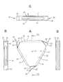
本発明の切削インサートを具体化した実施の形態例について、図1−図3に基づいて詳細に説明する。本例の切削インサート101は、略三角形(正三角形)で一定厚さの板(平板)10をベースに、その3つの各コーナ20に、その板10の厚み方向に切れ刃稜が延びる前切れ刃21を備える三角チップとして構成されている。なお、本例では、各コーナ20に設けられている、前切れ刃21、及び横切れ刃22は、同じ形状、構造のものである。すなわち、本例の切削インサート101は、三角形の板10としてその1主面(板の表面)11を見たとき(図2−A参照)、その中心O回りに、120度の等角度間隔で前切れ刃21を備えるものであり、かつ、3回の回転対称性を有する形状のものであるため、以下、その1つの前切れ刃21(図1の左の前切れ刃21、図2−Aの左上の前切れ刃)を中心に説明する。
The embodiment which actualized the cutting insert of this invention is described in detail based on FIGS. 1-3. The cutting
本例の切削インサート(三角チップ)101の形状、構造は、一定厚さの正三角形の基材(平らな板)をベースに、三角形の外周面(三角板の周囲3辺における厚み面)のうち、その各コーナ20を挟み、そのコーナ20寄りの両面が切欠き状ないしカット状に形成されて、それぞれ、すくい面23と、前逃げ面25とをなすものとされている。このうち、すくい面23は、図2−Aに示した、三角形の外周面のうち、図示における上横辺(外周面)31に対し、適度のポジのすくい角(例えば、25度)が付与され、前切れ刃21から離間するに従い低位となる平面をなしている。そして、その平面の後端において凹となす円弧状の傾斜壁面27を介して、同図示における上横辺31である上面(三角形の1辺である外周面(板10の厚み面))に連なるように形成されている。一方、前逃げ面25は、適度の前逃げ角(例えば、2度〜20度)が付けられるように、正三角形のコーナ20において直線状にカットされた形状を呈している。
The shape and structure of the cutting insert (triangular tip) 101 of this example is based on a regular triangular base material (flat plate) having a certain thickness, and is based on a triangular outer peripheral surface (thickness surface on three sides around the triangular plate). Each of the
本例では、前切れ刃21の刃幅(すくい面23側又は前逃げ面25側から見たときの前切れ刃21(切れ刃稜)の長さ)H1は、三角形の板10の中央部分を含む平板部分の厚みT1より大きく形成されている(図3−B参照)。しかも、前切れ刃21をすくい面23側から見たとき、横切れ刃22には、その前切れ刃21における左右の各端縁21bから後方に向けてすくい面23の幅を小さくするようにバックレーキ角が付与されて延びている。そして、この横切れ刃22を含む前切れ刃21寄り部位が、その板10の各主面(両面)11より外方に存する(突出する)ように設けられている。すなわち、前切れ刃21を含むすくい面23を、すくい面23の上方から見たとき、前切れ刃21の両端21bと共に、すくい面23の両側に位置する横切れ刃22を含む部分が、基板10の表裏の各面(主面)11よりも、微量ではあるが外方に存し、他より厚肉部をなすように形成されている。
In this example, the width of the front cutting edge 21 (the length of the front cutting edge 21 (cutting edge) when viewed from the
ただし、このように外方に存している厚肉部は、横切れ刃22の後端22bと、前逃げ面25の高さ範囲における下端25bとを直線L1で結んだ部分(横逃げ面29を、前切れ刃21に平行な直線方向に見通したときにおける前切れ刃21寄りの三角領域)であり、この部分が、その板10の表裏の各面(主面)11において突出する設定とされている。なお、板10の両面11側とも、横切れ刃22の逃げ面(横逃げ面29)には、適度の横逃げ角が付けられている。しかして、1つのコーナ20の前切れ刃21を、板10の面11に沿う方向に、被削材の外周面に向けて縦送りする形態の溝入れ加工においては、理論上、当該インサート101自体についてみれば、当該前切れ刃21から三角板10の中心Oを越える溝深さであるとしても、切り込みができる設定となっている。
However, the thick portion existing outside in this way is a portion (lateral clearance surface 29) where the
さて、このような本例の切削インサート101をなす板10(三角形の板)の外周面31のうち、隣接する前切れ刃21相互間における外周面部分には、板10の厚みT1方向(前切れ刃の刃幅H1方向)の中央において、ホルダへのクランプにおいて被クランプ部をなすように、前切れ刃21相互間の方向に延びる凹溝33が設けられている。ただし、この凹溝33は、本例では横断面が左右対称の略V字状をなし、同一横断面で、三角チップの各辺に沿う前切れ刃21相互間の方向に延び、1つの前切れ刃21のすくい面23における傾斜壁面27と、隣接する別の前切れ刃21の前逃げ面25とに向けて、それぞれ貫通するよう連続して直線状に延びる形で設けられている。なお、この凹溝33は、板10の厚みT1に近い寸法の開口幅でV字溝をなし、そのV字の溝角度は、例えば、約90度に設定されており、その溝底にはアールが付けられている。
Of the outer
このような本例の切削インサート101によれば、3コーナの切れ刃を有するものであるから、1コーナ又は2コーナの切れ刃のものに比べ、切れ刃数が多いため、その分、1つの切削インサート101で多くの加工ができるから、工具(切れ刃単価)コスト、及び加工コストの低減が期待される。また、三角チップでありながら、三角板10の中央にクランプ(ネジ止め)用のスクリュー穴が設けられていない。すなわち、従来における三角チップのように、その中央に設けられたスクリュー穴に止めネジを通してホルダへクランプして切削工具とするものではなく、三角形の切削インサート101の外周面31のうち、隣接する前切れ刃21相互間における外周面部分に上記した凹溝(被クランプ部)33が設けられている。このため、以下において詳述するように、ホルダの先端部におけるクランプ部(着座部)、さらには押え具における押圧部を、この凹溝33が嵌合できる凸部形状のものとしておくと共に、その凸部の幅を本例インサート101の厚み、正確には、前切れ刃21の刃幅H1より狭い寸法としておき、このようなホルダにこの切削インサート101をクランプして切削工具とすることで、前切れ刃21から三角チップの中心Oを越えるような深い溝入れに対応できる。そして、そのようなクランプにおいては、その嵌合状態に基づき、三角チップは横方向にも前後方向にも安定した固定が得られる。以下、図4−図8に基づき、上記した切削インサート101をクランプしてなる切削工具201の一例について詳細に説明する。
According to such a
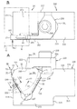
まず、切削工具201を構成するホルダ200について説明する。本例のホルダ200は、横断面が略正方形で棒状をなすシャンク(一部省略)210と、その先端においてシャンク210の横幅において下面213側に矩形で突出する先端部(ヘッド)215を有している。本例ではその先端部215において、シャンク210の一方の側面(横壁)217に沿い、後述するように上面219に向けて切りあがる形で略1/4円弧状のポケット(凹部)221が設けられているが、このポケット221と反対側の側面(横壁)223に沿って、三角チップ101の1つのコーナ20を挟む2辺における、2つの外周面部分(被クランプ部)を拘束するための着座部(クランプ部)230が設けられている。この2つの着座部(以下、クランプ部ともいう)230は、側面視、60度の開き角で、上方を開放する左右(ホルダ200の前後)対称のV字状に形成され、そのV字をなす2つの着座部230、230のうちのホルダ200の後方を向いて傾斜する先端側のものが、先方を向いて傾斜する後方のものより上端を相対的に低位とし、ホルダ200の先端面216にその傾斜角で切り上がり、略1/4円弧状のポケット(凹部)221の底部(下部)から立ち上がるように形成されている。また、後方の着座部230の上端が、ホルダ200の上面219より低位となるように、切欠き状に凹部(逃げ)225が設けられている。
First, the
一方、この前後2つの着座部230、230は、三角チップの1つのコーナ20(前切れ刃21)を下にして、そのコーナ20を挟む2つの外周面部分を介して着座させたとき、そのコーナ20に対向する1つの辺である外周面部分(横向きに延びる上横辺31)が、ホルダ200の上面219より若干上に位置し、かつ、ホルダ200の先端面216から突出する前切れ刃(切削を担う前切れ刃21)の前逃げ面25と、後方に位置する前切れ刃21のすくい面23の各部分が、着座部230の上端より上方に位置する設定とされている。また、2つの着座部230の下端(V字をなす2つの着座部230の交差部)は、下方に位置する別の前切れ刃21が干渉しないように、半円状に切り込まれて凹部(逃げ)227をなしている。なお、これらの着座部230は、インサート101をなす板10の厚みT1と同じか、それより小さい幅でもってV字の各辺(三角チップの2辺に相当)に沿うように延びている。ただし、この着座部230は、横断面において切削インサート101の外周面部分における凹溝(被クランプ部)33に嵌合する台形山形状を呈し、クランプ部をなしている。
On the other hand, when the two front and
なお、ホルダ200の先端部215のうち、このような着座部(クランプ部)230と反対側の側面(横壁)217に沿っては、上記もしたように、1/4円弧状のポケット(凹部)221が切り欠き形成されている。すなわち、ホルダ200の先端部215のうち、クランプ部と反対側には、ホルダ200を先端面216から見たとき、その先端面216の下部を残し、後方、上面219に向かって略1/4円弧状に切りあがる形で切欠かかれたポケット(1/4円弧状凹部)221が形成されている。このポケット221は、被削材の溝入れ加工において、被削材が工具に干渉することなく、深い切り込みを可能とする部位である。ただし、この1/4円弧状の切り込みは、後方の着座部230側と、前方の着座部230の下部、そして、交差部(半円状の逃げ)の部分に壁229を残すように形成されている。
In addition, along the side surface (lateral wall) 217 opposite to the seating portion (clamp portion) 230 in the
そして、このようなホルダ200における先端部215の上面219には、クランプするインサート101における上方の被クランプ部である外周面部分(凹溝33)を押え付ける押え具250が、ねじ部材(例えば、六角穴付きボルト)290を、ホルダ200における1/4円弧状のポケット(凹部)221の後方の上面219に設けられたネジ穴(図示せず)にねじ込むことで装着されている。ただし、この押え具250は、上面視(図5−B参照)、ネジ部材挿通穴のある基部251と、上面視において前後に細長く延びるクランプ部255とで概略L字形を呈しており、クランプ部255の先端の下部には、インサート101の上方の被クランプ部である外周面部分(凹溝33)を押え付ける押圧部260を備えている(図5−A参照)。そして、ねじ部材290のねじ込みにより、その押圧部260にて、インサート101の上方に位置する外周面部分(凹溝33)のうち、本例では、該外周面部分の前後両端に位置する前切れ刃21、21相互の中間よりも後方寄り位置を押え付ける設定とされている。
And, on the
なお、その押圧部(下面)260は、上記した着座部230と同様、その横断面において切削インサート101の外周面部分における凹溝33に嵌合する台形山形状を呈している。ただし、その押圧部260のインサート101の厚み方向の寸法(幅寸法)は、その上方及び後方部分(クランプ部255)を含め、インサート101の板10の厚さT1より小さくされている。そして、押さえつけ時において、押圧部260が、インサート101の上方に位置する外周面部分において、板10の両主面から外方に出ない設定とされている。しかして、被削材への溝入れ加工においては、先方に位置して立ち上がる着座部230と、この押え具250における押圧部260を含むクランプ部255が、被削材に干渉しないように形成されている。
In addition, the press part (lower surface) 260 is exhibiting the trapezoid mountain shape fitted to the ditch | groove 33 in the outer peripheral surface part of the cutting
このような本例においては、ホルダ200におけるクランプ部の側面視V字状をなす2つの着座部(台形山)230に、三角チップ101における1つのコーナ(前切れ刃21)20を挟む2つの外周面部分(凹溝33)を嵌合させ、その状態において、上の外周面部分(凹溝33)に、押え具250のクランプ部255における押圧部(下部の台形山)260を嵌合させ、そして、押え具250のねじ部材290をねじ込む。かくして、溝入れ用の切削工具201となるところ、このような切削工具201によって被削材の例えば外周面を旋削により溝入れ(又は突っ切り)加工をする場合には、次のような効果が得られる。
In this example, two corners (front cutting edge 21) 20 of the
すなわち、このような切削工具201による被削材Wへの溝入れ加工においては、上述もしたように、切削インサート101が、3コーナの切れ刃を有するものであるから、1コーナ又は2コーナの切れ刃のものに比べ、切れ刃数が多いため、その分、この1つの切削インサート101で多くの加工ができるから、切れ刃単価及び加工コストの低減も期待される。そして、1つのコーナ20の前切れ刃21の寿命後においては、本例では、回転対称性の形状とされているため、クランプを緩めて三角チップ(インサート101)をその板10の中心O回りに、120度回転させて再クランプし、別のコーナ20の前切れ刃21でさらに加工をすすめることができるから、その更新の段取りも容易に行える。本例の切削インサート101は、図2−A(図5−A)等に明示した通りの三角チップであり、その略三角の輪郭において3回の回転対称性の多角形のものである。なお、上述もしたように、例えば、本例のインサート101の3つの各前切れ刃21寄り部位に、その識別用にそれぞれ異なる形状、又は大きさの切り込みを設けて、部分的な形状相違があるものとなっても、1つのホルダにおいて、一定角度(本例では120度)の回転角で、前切れ刃(コーナ)の交換(クランプ)ができることに変わりはなく、したがって、このようにしても、3回の回転対称性のあるものといえる。
That is, in the grooving process to the work material W by the
また、本例では三角チップでありながら、従来における三角チップのように、三角板の中央に設けられたスクリュー穴を用いてホルダへのクランプをするクランプ構造ではない。そして上記したように、前方において立ち上がる着座部230、押圧部260が前切れ刃21の刃幅H1の範囲内にあるようにしてクランプされている。このため、実際に溝入れ加工を担う前切れ刃21から三角チップの中心Oを超えても、1/4円弧状のポケット(凹部)221の円弧面に被削材Wが干渉する直前までの切り込みができる(図5−B,図8参照)。このように本例切削工具201によれば、従来にない深い溝入れ加工ができるから、太い丸棒の突っ切りにも適するものとなるなど、その効果には著しいものがある。
Moreover, although it is a triangular tip in this example, it is not the clamp structure which clamps to a holder using the screw hole provided in the center of a triangular plate like the conventional triangular tip. As described above, the
しかも、上記例の切削インサート101は、その外周面部分(凹溝33)を被クランプ部として、ホルダ200側の着座部230、押圧部260の台形山との嵌合によるクランプ構造を有している。このため、横方向(図5−Bの矢印A5方向、すなわち、図5−Bの被削材Wの回転軸G(1点鎖線)方向)への外力が作用しても、その3箇所の外周面部(凹溝33)における嵌合構造によってそれに抗することができる。結果、高強度材の溝入れにおいても、横ぶれを招かないので、高精度な溝加工ができる。また、自動送り出し装置付きの旋盤のように、加工終了後に材料が送り出され、その位置決めをインサート101の横面(板10の主面)で行う場合においても、その際の横荷重でインサートが動くといったことも防止できる。さらに、上記例の切削工具201においては、前後の2つの着座部230が、それぞれ、後方又は前方を向いて傾斜しているから、三角チップが後方だけでなく、前方に移動するのも構造的に防止されている。したがって、溝入れ後に切削工具201を縦送りから戻す際、或いは、前切れ刃21を前後動するようなことがあって、溝壁面との摩擦が如何に大きくなるとしても、インサート101がホルダ200からの抜け出して脱落することを確実に防止できる。
In addition, the cutting
なお、上記例では、横方向への外力に抗する手段として、切削インサート101をなす多角形の板10の外周面のうち、隣接する前切れ刃21相互間における外周面部分に、前切れ刃21相互間の方向に延びる凹溝33を設けたものにおいて説明したが、本発明では、このような凹溝33に代えて、図9に示したように、凸条35を設けておいてもよい。その凸条35の横断面は、例えば、上記例における着座部230や押え具の押圧部260の台形山形状としておけばよい。そして、このような場合には、嵌合の相手側であるホルダ200における着座部230や押え具の押圧部260の下部の横断面形状を、逆に、その凸条35に嵌合する凹溝としておけばよい。なお、これら凹溝又は凸条の横断面は、V字形、台形等の適宜の横断面形状のものとすればよい。
In the above example, as a means against the external force in the lateral direction, the front cutting edge is formed on the outer peripheral surface portion between the adjacent
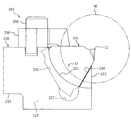
また、上記例では、三角チップの場合で説明したが、本発明における多角形は、これに限定されるものではなく、それより多くの4以上のコーナを有する多角形のものとしても具体化できる。図10、図11は、その一例を示したものであり、五角形の切削インサート501である。この切削インサート501は正五角形の板10をベースに、その5つのコーナ20において、前切れ刃21を形成したものである。図11は、これをホルダ200にクランプしてなる切削工具601として具体化したものである。このものでは、コーナ20数が多い分、さらなるコストの低減が期待される。なお、図11のものでは、切削インサート501をなす多角形の板の外周面のうち、隣接する前切れ刃21相互間における外周面部分に、前切れ刃21相互間の方向に延びる凹溝33とした場合を例示しているが、それに代えて凸条としてもよい。このものでは、5つの切れ刃としているため、ホルダ200における着座面230のうち、前方に位置し、後方に向けて傾斜するものの傾斜角が、上記三角チップにおける場合に比べて小さくなっているが、それでも、傾斜角がある分、切削インサート501が前方に抜け出るのを構造的に防止されているなど、上記例と同様の効果が得られる。すなわち、このものは、コーナ数が異なる点と、その相違に基づく、前記したような相違点はあるが、他には上記例との相違点はないので、同一、又は対応する部位に同一の符号を付すに止め、他の説明は省略する。
In the above example, the case of a triangular chip has been described. However, the polygon in the present invention is not limited to this, and can be embodied as a polygon having more than four corners. . FIG. 10 and FIG. 11 show an example thereof, which is a
本発明における切削インサート、さらには切削工具は、上記した各例におけるものに限定されるものではなく、その要旨を逸脱しない範囲において、適宜に変更して具体化できる。すなわち、切削インサート、切削工具は、加工対象である溝の幅や、溝入れ深さ等に応じて、適宜の寸法、形状、構造のものとして具体化できる。また、上記例では、外周面における溝入れの場合で説明したが、端面における溝入れにも適用できる。なお、切削インサートは、公知の各材料製のものとして具体化できることは明らかである。 The cutting insert and further the cutting tool in the present invention are not limited to those in each of the above-described examples, and can be appropriately changed and embodied without departing from the gist thereof. That is, the cutting insert and the cutting tool can be embodied as having an appropriate size, shape, and structure according to the width of the groove to be processed, the grooving depth, and the like. Further, in the above example, the case of grooving on the outer peripheral surface has been described, but it can also be applied to grooving on the end face. It is obvious that the cutting insert can be embodied as a known material.
10 多角形の板
11 板の主面
20 コーナ
21 前切れ刃
21b 前切れ刃における端縁
31 外周面部分
33 凹溝
35 凸条
101、501 切削インサート(三角チップ)
T1 板の厚み
H1 刃幅
200 ホルダ
201、601 切削工具
215 ホルダの先端部
230 着座部
250 押え具
260 押圧部
DESCRIPTION OF
T1 Plate thickness
Claims (3)
この前切れ刃は、前記板の厚み方向における刃幅が該板の厚みより大きく、しかも、この前切れ刃における各端縁が、該板の各主面より外方に存するように設けられており、
前記板の外周面のうち、隣接する前切れ刃相互間における各外周面部分に、該前切れ刃相互間の方向に延びる凹溝又は凸条が設けられていることを特徴とする切削インサート。 A polygonal plate having at least three corners, the cutting insert having a front cutting edge extending at at least the three corners in which the cutting edge ridge extends in the thickness direction of the plate,
The front cutting edge is provided such that the blade width in the thickness direction of the plate is larger than the thickness of the plate, and each edge of the front cutting edge is located outward from each main surface of the plate. And
A cutting insert characterized in that a concave groove or a ridge extending in a direction between the front cutting edges is provided in each outer peripheral surface portion between adjacent front cutting edges in the outer peripheral surface of the plate.
該ホルダは、その先端部に該切削インサートをクランプするためのクランプ部を備えており、このクランプ部は、該切削インサートにおける前記外周面部分のうち、2つの外周面部分における前記凹溝又は前記凸条を、前後の位置において嵌合させ得る2つの着座部を有し、かつ、この2つの着座部は、このクランプ部内での該切削インサートの前後動を規制し得るように、前方のものは後方を向いて傾斜し、後方のものは前方を向いて傾斜して形成されている一方、
該ホルダとは別に、前記2つの着座部への、前記2つの外周面部分における前記凹溝又は前記凸条の嵌合状態において、他の1つの前記外周面部分における前記凹溝又は前記凸条に嵌合させ得る押圧部を有し、かつ、その嵌合状態において前記2つの着座部に向けて該切削インサートを押え付けてクランプできるように構成されている押圧部付きの押え具とを含んでおり、
該切削インサートは、前記2つの着座部に、該切削インサートの2つの前記外周面部分における前記凹溝又は前記凸条を嵌合させられていると共に、前記押え具の押圧部が、他の1つの前記外周面部分における前記凹溝又は前記凸条に嵌合させられており、その嵌合状態において、前記押え具が、前記2つの着座部に向けて該切削インサートを押え付けてクランプしていることを特徴とする切削工具。
A cutting tool in which the cutting insert according to claim 2 is clamped to a holder,
The holder includes a clamp portion for clamping the cutting insert at a tip portion thereof, and the clamp portion includes the concave groove or the two of the outer peripheral surface portions of the cutting insert. The seat has two seating portions that can be fitted in the front and rear positions, and the two seating portions are arranged in front so that the longitudinal movement of the cutting insert in the clamp portion can be restricted. Is inclined to the rear and the rear one is inclined to the front,
Separately from the holder, in the fitting state of the concave groove or the ridge in the two outer peripheral surface portions to the two seating portions, the concave groove or the ridge in the other outer peripheral surface portion. And a pressing tool with a pressing portion configured to press and clamp the cutting insert toward the two seating portions in the fitted state. And
The cutting insert has the two seating portions fitted with the concave grooves or the ridges in the two outer peripheral surface portions of the cutting insert, and the pressing portion of the presser is the other one. Are fitted in the concave grooves or the ridges in the two outer peripheral surface portions, and in the fitted state, the presser clamps and clamps the cutting insert toward the two seating portions. A cutting tool characterized by
Priority Applications (1)
| Application Number | Priority Date | Filing Date | Title |
|---|---|---|---|
| JP2016071428A JP2017177307A (en) | 2016-03-31 | 2016-03-31 | Cutting insert and cutting tool |
Applications Claiming Priority (1)
| Application Number | Priority Date | Filing Date | Title |
|---|---|---|---|
| JP2016071428A JP2017177307A (en) | 2016-03-31 | 2016-03-31 | Cutting insert and cutting tool |
Publications (1)
| Publication Number | Publication Date |
|---|---|
| JP2017177307A true JP2017177307A (en) | 2017-10-05 |
Family
ID=60008980
Family Applications (1)
| Application Number | Title | Priority Date | Filing Date |
|---|---|---|---|
| JP2016071428A Pending JP2017177307A (en) | 2016-03-31 | 2016-03-31 | Cutting insert and cutting tool |
Country Status (1)
| Country | Link |
|---|---|
| JP (1) | JP2017177307A (en) |
Cited By (2)
| Publication number | Priority date | Publication date | Assignee | Title |
|---|---|---|---|---|
| JP2021000695A (en) * | 2019-06-21 | 2021-01-07 | アイシン機工株式会社 | Cutting tool, tool holder, and tool fixing structure |
| RU2747085C2 (en) * | 2016-09-13 | 2021-04-26 | Искар Лтд. | Cutting tool with rotary cutting plate |
Citations (13)
| Publication number | Priority date | Publication date | Assignee | Title |
|---|---|---|---|---|
| JPS4963072A (en) * | 1972-06-17 | 1974-06-19 | ||
| JPS5570905U (en) * | 1978-11-09 | 1980-05-16 | ||
| JPS5775905U (en) * | 1980-10-28 | 1982-05-11 | ||
| US4602897A (en) * | 1984-04-25 | 1986-07-29 | Iscar Metals, Inc. | Cutting insert and grooving cutter |
| JPH0871812A (en) * | 1994-09-12 | 1996-03-19 | Mitsubishi Materials Corp | Grooving tool and throw away tip |
| JPH11129102A (en) * | 1997-08-29 | 1999-05-18 | Ngk Spark Plug Co Ltd | Manufacture of throw-away chip and throw-away chip |
| JP2005517538A (en) * | 2002-02-19 | 2005-06-16 | イスカーリミテッド | Metal cutting tools |
| JP2008105115A (en) * | 2006-10-24 | 2008-05-08 | Mitsubishi Materials Corp | Cutting tool |
| US20090162154A1 (en) * | 2007-12-20 | 2009-06-25 | Seco Tools Ab | Indexable turning insert and a cutting tool comprising such an insert |
| JP2011161538A (en) * | 2010-02-05 | 2011-08-25 | Mitsubishi Materials Corp | Cutting edge replacement type groove forming tool and peripheral surface groove forming method |
| WO2012173255A1 (en) * | 2011-06-17 | 2012-12-20 | 株式会社タンガロイ | Cutting insert and rotary cutting tool |
| JP2015520038A (en) * | 2012-06-19 | 2015-07-16 | イスカル リミテッド | Thread cutting tool and double-side indexable thread cutting insert |
| JP2018534156A (en) * | 2015-11-18 | 2018-11-22 | イスカル リミテッド | Cutting tool and triangular indexable cutting insert therefor |
-
2016
- 2016-03-31 JP JP2016071428A patent/JP2017177307A/en active Pending
Patent Citations (13)
| Publication number | Priority date | Publication date | Assignee | Title |
|---|---|---|---|---|
| JPS4963072A (en) * | 1972-06-17 | 1974-06-19 | ||
| JPS5570905U (en) * | 1978-11-09 | 1980-05-16 | ||
| JPS5775905U (en) * | 1980-10-28 | 1982-05-11 | ||
| US4602897A (en) * | 1984-04-25 | 1986-07-29 | Iscar Metals, Inc. | Cutting insert and grooving cutter |
| JPH0871812A (en) * | 1994-09-12 | 1996-03-19 | Mitsubishi Materials Corp | Grooving tool and throw away tip |
| JPH11129102A (en) * | 1997-08-29 | 1999-05-18 | Ngk Spark Plug Co Ltd | Manufacture of throw-away chip and throw-away chip |
| JP2005517538A (en) * | 2002-02-19 | 2005-06-16 | イスカーリミテッド | Metal cutting tools |
| JP2008105115A (en) * | 2006-10-24 | 2008-05-08 | Mitsubishi Materials Corp | Cutting tool |
| US20090162154A1 (en) * | 2007-12-20 | 2009-06-25 | Seco Tools Ab | Indexable turning insert and a cutting tool comprising such an insert |
| JP2011161538A (en) * | 2010-02-05 | 2011-08-25 | Mitsubishi Materials Corp | Cutting edge replacement type groove forming tool and peripheral surface groove forming method |
| WO2012173255A1 (en) * | 2011-06-17 | 2012-12-20 | 株式会社タンガロイ | Cutting insert and rotary cutting tool |
| JP2015520038A (en) * | 2012-06-19 | 2015-07-16 | イスカル リミテッド | Thread cutting tool and double-side indexable thread cutting insert |
| JP2018534156A (en) * | 2015-11-18 | 2018-11-22 | イスカル リミテッド | Cutting tool and triangular indexable cutting insert therefor |
Cited By (3)
| Publication number | Priority date | Publication date | Assignee | Title |
|---|---|---|---|---|
| RU2747085C2 (en) * | 2016-09-13 | 2021-04-26 | Искар Лтд. | Cutting tool with rotary cutting plate |
| JP2021000695A (en) * | 2019-06-21 | 2021-01-07 | アイシン機工株式会社 | Cutting tool, tool holder, and tool fixing structure |
| JP7345291B2 (en) | 2019-06-21 | 2023-09-15 | アイシン機工株式会社 | Cutting tools, tool holders and tool fixing structures |
Similar Documents
| Publication | Publication Date | Title |
|---|---|---|
| JP5580400B2 (en) | Cutting tool assembly and its tool holder | |
| US20110255926A1 (en) | Cutting Tool and Cutting Insert Therefor | |
| EP1263543B1 (en) | Cutting tool assembly | |
| JP2012518548A (en) | Cutting tool with adjusting mechanism | |
| JP2006528079A (en) | Cutting head for rotary cutting tools | |
| JP4918799B2 (en) | Cutting insert clamping mechanism and insert detachable cutting tool | |
| US10252344B2 (en) | Cutting tool | |
| JP2774972B2 (en) | Cutting insert | |
| JP5157660B2 (en) | Cutting insert and insert detachable cutting tool | |
| US3310859A (en) | Cutting tool | |
| KR930002410B1 (en) | Cutting insert with chip control | |
| US5288180A (en) | Cutting tool | |
| US6543318B1 (en) | Locking assembly | |
| JP2017177307A (en) | Cutting insert and cutting tool | |
| USRE25955E (en) | Grooving tool | |
| US6231274B1 (en) | End mill | |
| JP4815366B2 (en) | Cutting inserts and holders and cutting tools | |
| KR102293756B1 (en) | Metal-cutting grooving inserts for face grooving | |
| JP3286836B2 (en) | Indexable bite and its shank | |
| US6824333B1 (en) | Grooving and turning tool with clamping surfaces | |
| JP5882822B2 (en) | Fixed member and cutting tool | |
| US7568865B1 (en) | Thread forming tool assembly | |
| US7011476B1 (en) | Double-ended grooving and turning tool with clamping surfaces | |
| CN114632963A (en) | Method for positioning machining tool and machining tool | |
| JP2014034066A (en) | Insert and cutting tool |
Legal Events
| Date | Code | Title | Description |
|---|---|---|---|
| A621 | Written request for application examination |
Free format text: JAPANESE INTERMEDIATE CODE: A621 Effective date: 20181015 |
|
| A977 | Report on retrieval |
Free format text: JAPANESE INTERMEDIATE CODE: A971007 Effective date: 20190731 |
|
| A131 | Notification of reasons for refusal |
Free format text: JAPANESE INTERMEDIATE CODE: A131 Effective date: 20190806 |
|
| A521 | Request for written amendment filed |
Free format text: JAPANESE INTERMEDIATE CODE: A523 Effective date: 20190918 |
|
| A131 | Notification of reasons for refusal |
Free format text: JAPANESE INTERMEDIATE CODE: A131 Effective date: 20200218 |
|
| A02 | Decision of refusal |
Free format text: JAPANESE INTERMEDIATE CODE: A02 Effective date: 20200929 |