EP2676475B1 - Leistungsreservebericht - Google Patents
Leistungsreservebericht Download PDFInfo
- Publication number
- EP2676475B1 EP2676475B1 EP12747557.2A EP12747557A EP2676475B1 EP 2676475 B1 EP2676475 B1 EP 2676475B1 EP 12747557 A EP12747557 A EP 12747557A EP 2676475 B1 EP2676475 B1 EP 2676475B1
- Authority
- EP
- European Patent Office
- Prior art keywords
- phr
- serving cell
- terminal
- power
- transmission
- Prior art date
- Legal status (The legal status is an assumption and is not a legal conclusion. Google has not performed a legal analysis and makes no representation as to the accuracy of the status listed.)
- Active
Links
- 230000005540 biological transmission Effects 0.000 claims description 88
- 238000000034 method Methods 0.000 claims description 60
- 230000001960 triggered effect Effects 0.000 claims description 26
- 238000004891 communication Methods 0.000 claims description 9
- 230000009467 reduction Effects 0.000 description 19
- 238000010586 diagram Methods 0.000 description 18
- 238000007726 management method Methods 0.000 description 17
- 230000002776 aggregation Effects 0.000 description 16
- 238000004220 aggregation Methods 0.000 description 16
- 239000000969 carrier Substances 0.000 description 14
- 238000010295 mobile communication Methods 0.000 description 14
- 230000008569 process Effects 0.000 description 7
- 230000008859 change Effects 0.000 description 6
- 230000006978 adaptation Effects 0.000 description 3
- 238000004364 calculation method Methods 0.000 description 3
- 102100027715 4-hydroxy-2-oxoglutarate aldolase, mitochondrial Human genes 0.000 description 2
- 101001081225 Homo sapiens 4-hydroxy-2-oxoglutarate aldolase, mitochondrial Proteins 0.000 description 2
- 101001109518 Homo sapiens N-acetylneuraminate lyase Proteins 0.000 description 2
- 101000604027 Homo sapiens Nuclear protein localization protein 4 homolog Proteins 0.000 description 2
- 101000974007 Homo sapiens Nucleosome assembly protein 1-like 3 Proteins 0.000 description 2
- 101001099181 Homo sapiens TATA-binding protein-associated factor 2N Proteins 0.000 description 2
- 102100022686 N-acetylneuraminate lyase Human genes 0.000 description 2
- 102100038438 Nuclear protein localization protein 4 homolog Human genes 0.000 description 2
- 102100038917 TATA-binding protein-associated factor 2N Human genes 0.000 description 2
- 230000015572 biosynthetic process Effects 0.000 description 2
- 230000007423 decrease Effects 0.000 description 2
- 238000005516 engineering process Methods 0.000 description 2
- 230000007774 longterm Effects 0.000 description 2
- 230000000737 periodic effect Effects 0.000 description 2
- 230000005855 radiation Effects 0.000 description 2
- 238000013468 resource allocation Methods 0.000 description 2
- 230000004044 response Effects 0.000 description 2
- 230000011664 signaling Effects 0.000 description 2
- 238000010521 absorption reaction Methods 0.000 description 1
- 230000009471 action Effects 0.000 description 1
- 230000003044 adaptive effect Effects 0.000 description 1
- 230000001174 ascending effect Effects 0.000 description 1
- 230000010267 cellular communication Effects 0.000 description 1
- 230000006835 compression Effects 0.000 description 1
- 238000007906 compression Methods 0.000 description 1
- 238000010276 construction Methods 0.000 description 1
- 230000006837 decompression Effects 0.000 description 1
- 238000001514 detection method Methods 0.000 description 1
- 230000009977 dual effect Effects 0.000 description 1
- 230000000694 effects Effects 0.000 description 1
- 230000007257 malfunction Effects 0.000 description 1
Images


Classifications
-
- H—ELECTRICITY
- H04—ELECTRIC COMMUNICATION TECHNIQUE
- H04W—WIRELESS COMMUNICATION NETWORKS
- H04W52/00—Power management, e.g. TPC [Transmission Power Control], power saving or power classes
- H04W52/04—TPC
- H04W52/30—TPC using constraints in the total amount of available transmission power
- H04W52/36—TPC using constraints in the total amount of available transmission power with a discrete range or set of values, e.g. step size, ramping or offsets
- H04W52/365—Power headroom reporting
-
- H—ELECTRICITY
- H04—ELECTRIC COMMUNICATION TECHNIQUE
- H04L—TRANSMISSION OF DIGITAL INFORMATION, e.g. TELEGRAPHIC COMMUNICATION
- H04L1/00—Arrangements for detecting or preventing errors in the information received
- H04L1/12—Arrangements for detecting or preventing errors in the information received by using return channel
- H04L1/16—Arrangements for detecting or preventing errors in the information received by using return channel in which the return channel carries supervisory signals, e.g. repetition request signals
- H04L1/18—Automatic repetition systems, e.g. Van Duuren systems
- H04L1/1829—Arrangements specially adapted for the receiver end
- H04L1/1835—Buffer management
-
- H—ELECTRICITY
- H04—ELECTRIC COMMUNICATION TECHNIQUE
- H04L—TRANSMISSION OF DIGITAL INFORMATION, e.g. TELEGRAPHIC COMMUNICATION
- H04L1/00—Arrangements for detecting or preventing errors in the information received
- H04L1/12—Arrangements for detecting or preventing errors in the information received by using return channel
- H04L1/16—Arrangements for detecting or preventing errors in the information received by using return channel in which the return channel carries supervisory signals, e.g. repetition request signals
- H04L1/18—Automatic repetition systems, e.g. Van Duuren systems
- H04L1/1829—Arrangements specially adapted for the receiver end
- H04L1/1848—Time-out mechanisms
- H04L1/1851—Time-out mechanisms using multiple timers
-
- H—ELECTRICITY
- H04—ELECTRIC COMMUNICATION TECHNIQUE
- H04L—TRANSMISSION OF DIGITAL INFORMATION, e.g. TELEGRAPHIC COMMUNICATION
- H04L1/00—Arrangements for detecting or preventing errors in the information received
- H04L1/12—Arrangements for detecting or preventing errors in the information received by using return channel
- H04L1/16—Arrangements for detecting or preventing errors in the information received by using return channel in which the return channel carries supervisory signals, e.g. repetition request signals
- H04L1/18—Automatic repetition systems, e.g. Van Duuren systems
- H04L1/1829—Arrangements specially adapted for the receiver end
- H04L1/1854—Scheduling and prioritising arrangements
-
- H—ELECTRICITY
- H04—ELECTRIC COMMUNICATION TECHNIQUE
- H04L—TRANSMISSION OF DIGITAL INFORMATION, e.g. TELEGRAPHIC COMMUNICATION
- H04L1/00—Arrangements for detecting or preventing errors in the information received
- H04L1/12—Arrangements for detecting or preventing errors in the information received by using return channel
- H04L1/16—Arrangements for detecting or preventing errors in the information received by using return channel in which the return channel carries supervisory signals, e.g. repetition request signals
- H04L1/18—Automatic repetition systems, e.g. Van Duuren systems
- H04L1/1867—Arrangements specially adapted for the transmitter end
- H04L1/1874—Buffer management
-
- H—ELECTRICITY
- H04—ELECTRIC COMMUNICATION TECHNIQUE
- H04L—TRANSMISSION OF DIGITAL INFORMATION, e.g. TELEGRAPHIC COMMUNICATION
- H04L1/00—Arrangements for detecting or preventing errors in the information received
- H04L1/12—Arrangements for detecting or preventing errors in the information received by using return channel
- H04L1/16—Arrangements for detecting or preventing errors in the information received by using return channel in which the return channel carries supervisory signals, e.g. repetition request signals
- H04L1/18—Automatic repetition systems, e.g. Van Duuren systems
- H04L1/1867—Arrangements specially adapted for the transmitter end
- H04L1/188—Time-out mechanisms
- H04L1/1883—Time-out mechanisms using multiple timers
-
- H—ELECTRICITY
- H04—ELECTRIC COMMUNICATION TECHNIQUE
- H04L—TRANSMISSION OF DIGITAL INFORMATION, e.g. TELEGRAPHIC COMMUNICATION
- H04L5/00—Arrangements affording multiple use of the transmission path
- H04L5/0001—Arrangements for dividing the transmission path
- H04L5/0003—Two-dimensional division
- H04L5/0005—Time-frequency
- H04L5/0007—Time-frequency the frequencies being orthogonal, e.g. OFDM(A), DMT
- H04L5/001—Time-frequency the frequencies being orthogonal, e.g. OFDM(A), DMT the frequencies being arranged in component carriers
-
- H—ELECTRICITY
- H04—ELECTRIC COMMUNICATION TECHNIQUE
- H04L—TRANSMISSION OF DIGITAL INFORMATION, e.g. TELEGRAPHIC COMMUNICATION
- H04L5/00—Arrangements affording multiple use of the transmission path
- H04L5/003—Arrangements for allocating sub-channels of the transmission path
- H04L5/0048—Allocation of pilot signals, i.e. of signals known to the receiver
-
- H—ELECTRICITY
- H04—ELECTRIC COMMUNICATION TECHNIQUE
- H04L—TRANSMISSION OF DIGITAL INFORMATION, e.g. TELEGRAPHIC COMMUNICATION
- H04L5/00—Arrangements affording multiple use of the transmission path
- H04L5/0091—Signaling for the administration of the divided path
- H04L5/0096—Indication of changes in allocation
- H04L5/0098—Signalling of the activation or deactivation of component carriers, subcarriers or frequency bands
-
- H—ELECTRICITY
- H04—ELECTRIC COMMUNICATION TECHNIQUE
- H04W—WIRELESS COMMUNICATION NETWORKS
- H04W28/00—Network traffic management; Network resource management
- H04W28/02—Traffic management, e.g. flow control or congestion control
- H04W28/04—Error control
-
- H—ELECTRICITY
- H04—ELECTRIC COMMUNICATION TECHNIQUE
- H04W—WIRELESS COMMUNICATION NETWORKS
- H04W52/00—Power management, e.g. TPC [Transmission Power Control], power saving or power classes
- H04W52/02—Power saving arrangements
- H04W52/0209—Power saving arrangements in terminal devices
- H04W52/0212—Power saving arrangements in terminal devices managed by the network, e.g. network or access point is master and terminal is slave
- H04W52/0216—Power saving arrangements in terminal devices managed by the network, e.g. network or access point is master and terminal is slave using a pre-established activity schedule, e.g. traffic indication frame
-
- H—ELECTRICITY
- H04—ELECTRIC COMMUNICATION TECHNIQUE
- H04W—WIRELESS COMMUNICATION NETWORKS
- H04W52/00—Power management, e.g. TPC [Transmission Power Control], power saving or power classes
- H04W52/02—Power saving arrangements
- H04W52/0209—Power saving arrangements in terminal devices
- H04W52/0212—Power saving arrangements in terminal devices managed by the network, e.g. network or access point is master and terminal is slave
- H04W52/0219—Power saving arrangements in terminal devices managed by the network, e.g. network or access point is master and terminal is slave where the power saving management affects multiple terminals
-
- H—ELECTRICITY
- H04—ELECTRIC COMMUNICATION TECHNIQUE
- H04W—WIRELESS COMMUNICATION NETWORKS
- H04W52/00—Power management, e.g. TPC [Transmission Power Control], power saving or power classes
- H04W52/04—TPC
- H04W52/06—TPC algorithms
- H04W52/14—Separate analysis of uplink or downlink
- H04W52/146—Uplink power control
-
- H—ELECTRICITY
- H04—ELECTRIC COMMUNICATION TECHNIQUE
- H04W—WIRELESS COMMUNICATION NETWORKS
- H04W52/00—Power management, e.g. TPC [Transmission Power Control], power saving or power classes
- H04W52/04—TPC
- H04W52/30—TPC using constraints in the total amount of available transmission power
- H04W52/36—TPC using constraints in the total amount of available transmission power with a discrete range or set of values, e.g. step size, ramping or offsets
- H04W52/367—Power values between minimum and maximum limits, e.g. dynamic range
-
- H—ELECTRICITY
- H04—ELECTRIC COMMUNICATION TECHNIQUE
- H04W—WIRELESS COMMUNICATION NETWORKS
- H04W52/00—Power management, e.g. TPC [Transmission Power Control], power saving or power classes
- H04W52/04—TPC
- H04W52/38—TPC being performed in particular situations
- H04W52/50—TPC being performed in particular situations at the moment of starting communication in a multiple access environment
-
- H—ELECTRICITY
- H04—ELECTRIC COMMUNICATION TECHNIQUE
- H04W—WIRELESS COMMUNICATION NETWORKS
- H04W52/00—Power management, e.g. TPC [Transmission Power Control], power saving or power classes
- H04W52/04—TPC
- H04W52/54—Signalisation aspects of the TPC commands, e.g. frame structure
-
- H—ELECTRICITY
- H04—ELECTRIC COMMUNICATION TECHNIQUE
- H04W—WIRELESS COMMUNICATION NETWORKS
- H04W52/00—Power management, e.g. TPC [Transmission Power Control], power saving or power classes
- H04W52/04—TPC
- H04W52/54—Signalisation aspects of the TPC commands, e.g. frame structure
- H04W52/545—Signalisation aspects of the TPC commands, e.g. frame structure modifying TPC bits in special situations
-
- H—ELECTRICITY
- H04—ELECTRIC COMMUNICATION TECHNIQUE
- H04W—WIRELESS COMMUNICATION NETWORKS
- H04W52/00—Power management, e.g. TPC [Transmission Power Control], power saving or power classes
- H04W52/04—TPC
- H04W52/54—Signalisation aspects of the TPC commands, e.g. frame structure
- H04W52/58—Format of the TPC bits
-
- H—ELECTRICITY
- H04—ELECTRIC COMMUNICATION TECHNIQUE
- H04W—WIRELESS COMMUNICATION NETWORKS
- H04W56/00—Synchronisation arrangements
- H04W56/0005—Synchronisation arrangements synchronizing of arrival of multiple uplinks
-
- H—ELECTRICITY
- H04—ELECTRIC COMMUNICATION TECHNIQUE
- H04W—WIRELESS COMMUNICATION NETWORKS
- H04W56/00—Synchronisation arrangements
- H04W56/001—Synchronization between nodes
-
- H—ELECTRICITY
- H04—ELECTRIC COMMUNICATION TECHNIQUE
- H04W—WIRELESS COMMUNICATION NETWORKS
- H04W56/00—Synchronisation arrangements
- H04W56/001—Synchronization between nodes
- H04W56/0015—Synchronization between nodes one node acting as a reference for the others
-
- H—ELECTRICITY
- H04—ELECTRIC COMMUNICATION TECHNIQUE
- H04W—WIRELESS COMMUNICATION NETWORKS
- H04W56/00—Synchronisation arrangements
- H04W56/004—Synchronisation arrangements compensating for timing error of reception due to propagation delay
- H04W56/0045—Synchronisation arrangements compensating for timing error of reception due to propagation delay compensating for timing error by altering transmission time
-
- H—ELECTRICITY
- H04—ELECTRIC COMMUNICATION TECHNIQUE
- H04W—WIRELESS COMMUNICATION NETWORKS
- H04W56/00—Synchronisation arrangements
- H04W56/004—Synchronisation arrangements compensating for timing error of reception due to propagation delay
- H04W56/005—Synchronisation arrangements compensating for timing error of reception due to propagation delay compensating for timing error by adjustment in the receiver
-
- H—ELECTRICITY
- H04—ELECTRIC COMMUNICATION TECHNIQUE
- H04W—WIRELESS COMMUNICATION NETWORKS
- H04W72/00—Local resource management
- H04W72/04—Wireless resource allocation
- H04W72/044—Wireless resource allocation based on the type of the allocated resource
- H04W72/0446—Resources in time domain, e.g. slots or frames
-
- H—ELECTRICITY
- H04—ELECTRIC COMMUNICATION TECHNIQUE
- H04W—WIRELESS COMMUNICATION NETWORKS
- H04W72/00—Local resource management
- H04W72/20—Control channels or signalling for resource management
- H04W72/21—Control channels or signalling for resource management in the uplink direction of a wireless link, i.e. towards the network
-
- H—ELECTRICITY
- H04—ELECTRIC COMMUNICATION TECHNIQUE
- H04W—WIRELESS COMMUNICATION NETWORKS
- H04W72/00—Local resource management
- H04W72/20—Control channels or signalling for resource management
- H04W72/23—Control channels or signalling for resource management in the downlink direction of a wireless link, i.e. towards a terminal
-
- H—ELECTRICITY
- H04—ELECTRIC COMMUNICATION TECHNIQUE
- H04W—WIRELESS COMMUNICATION NETWORKS
- H04W74/00—Wireless channel access, e.g. scheduled or random access
- H04W74/002—Transmission of channel access control information
- H04W74/006—Transmission of channel access control information in the downlink, i.e. towards the terminal
-
- H—ELECTRICITY
- H04—ELECTRIC COMMUNICATION TECHNIQUE
- H04W—WIRELESS COMMUNICATION NETWORKS
- H04W74/00—Wireless channel access, e.g. scheduled or random access
- H04W74/08—Non-scheduled or contention based access, e.g. random access, ALOHA, CSMA [Carrier Sense Multiple Access]
- H04W74/0833—Non-scheduled or contention based access, e.g. random access, ALOHA, CSMA [Carrier Sense Multiple Access] using a random access procedure
- H04W74/0841—Non-scheduled or contention based access, e.g. random access, ALOHA, CSMA [Carrier Sense Multiple Access] using a random access procedure with collision treatment
- H04W74/085—Non-scheduled or contention based access, e.g. random access, ALOHA, CSMA [Carrier Sense Multiple Access] using a random access procedure with collision treatment collision avoidance
-
- H—ELECTRICITY
- H04—ELECTRIC COMMUNICATION TECHNIQUE
- H04W—WIRELESS COMMUNICATION NETWORKS
- H04W74/00—Wireless channel access, e.g. scheduled or random access
- H04W74/08—Non-scheduled or contention based access, e.g. random access, ALOHA, CSMA [Carrier Sense Multiple Access]
- H04W74/0833—Non-scheduled or contention based access, e.g. random access, ALOHA, CSMA [Carrier Sense Multiple Access] using a random access procedure
- H04W74/0841—Non-scheduled or contention based access, e.g. random access, ALOHA, CSMA [Carrier Sense Multiple Access] using a random access procedure with collision treatment
- H04W74/0858—Non-scheduled or contention based access, e.g. random access, ALOHA, CSMA [Carrier Sense Multiple Access] using a random access procedure with collision treatment collision detection
-
- H—ELECTRICITY
- H04—ELECTRIC COMMUNICATION TECHNIQUE
- H04W—WIRELESS COMMUNICATION NETWORKS
- H04W74/00—Wireless channel access, e.g. scheduled or random access
- H04W74/08—Non-scheduled or contention based access, e.g. random access, ALOHA, CSMA [Carrier Sense Multiple Access]
- H04W74/0866—Non-scheduled or contention based access, e.g. random access, ALOHA, CSMA [Carrier Sense Multiple Access] using a dedicated channel for access
- H04W74/0891—Non-scheduled or contention based access, e.g. random access, ALOHA, CSMA [Carrier Sense Multiple Access] using a dedicated channel for access for synchronized access
-
- H—ELECTRICITY
- H04—ELECTRIC COMMUNICATION TECHNIQUE
- H04W—WIRELESS COMMUNICATION NETWORKS
- H04W76/00—Connection management
- H04W76/10—Connection setup
- H04W76/19—Connection re-establishment
-
- H—ELECTRICITY
- H04—ELECTRIC COMMUNICATION TECHNIQUE
- H04L—TRANSMISSION OF DIGITAL INFORMATION, e.g. TELEGRAPHIC COMMUNICATION
- H04L27/00—Modulated-carrier systems
- H04L27/26—Systems using multi-frequency codes
- H04L27/2601—Multicarrier modulation systems
- H04L27/2602—Signal structure
-
- H—ELECTRICITY
- H04—ELECTRIC COMMUNICATION TECHNIQUE
- H04L—TRANSMISSION OF DIGITAL INFORMATION, e.g. TELEGRAPHIC COMMUNICATION
- H04L27/00—Modulated-carrier systems
- H04L27/26—Systems using multi-frequency codes
- H04L27/2601—Multicarrier modulation systems
- H04L27/2647—Arrangements specific to the receiver only
- H04L27/2655—Synchronisation arrangements
- H04L27/2662—Symbol synchronisation
-
- H—ELECTRICITY
- H04—ELECTRIC COMMUNICATION TECHNIQUE
- H04W—WIRELESS COMMUNICATION NETWORKS
- H04W24/00—Supervisory, monitoring or testing arrangements
- H04W24/04—Arrangements for maintaining operational condition
-
- H—ELECTRICITY
- H04—ELECTRIC COMMUNICATION TECHNIQUE
- H04W—WIRELESS COMMUNICATION NETWORKS
- H04W48/00—Access restriction; Network selection; Access point selection
- H04W48/08—Access restriction or access information delivery, e.g. discovery data delivery
-
- H—ELECTRICITY
- H04—ELECTRIC COMMUNICATION TECHNIQUE
- H04W—WIRELESS COMMUNICATION NETWORKS
- H04W72/00—Local resource management
-
- H—ELECTRICITY
- H04—ELECTRIC COMMUNICATION TECHNIQUE
- H04W—WIRELESS COMMUNICATION NETWORKS
- H04W72/00—Local resource management
- H04W72/04—Wireless resource allocation
-
- H—ELECTRICITY
- H04—ELECTRIC COMMUNICATION TECHNIQUE
- H04W—WIRELESS COMMUNICATION NETWORKS
- H04W72/00—Local resource management
- H04W72/04—Wireless resource allocation
- H04W72/044—Wireless resource allocation based on the type of the allocated resource
- H04W72/0453—Resources in frequency domain, e.g. a carrier in FDMA
-
- H—ELECTRICITY
- H04—ELECTRIC COMMUNICATION TECHNIQUE
- H04W—WIRELESS COMMUNICATION NETWORKS
- H04W76/00—Connection management
- H04W76/30—Connection release
- H04W76/38—Connection release triggered by timers
-
- H—ELECTRICITY
- H04—ELECTRIC COMMUNICATION TECHNIQUE
- H04W—WIRELESS COMMUNICATION NETWORKS
- H04W84/00—Network topologies
- H04W84/02—Hierarchically pre-organised networks, e.g. paging networks, cellular networks, WLAN [Wireless Local Area Network] or WLL [Wireless Local Loop]
- H04W84/04—Large scale networks; Deep hierarchical networks
- H04W84/042—Public Land Mobile systems, e.g. cellular systems
-
- H—ELECTRICITY
- H04—ELECTRIC COMMUNICATION TECHNIQUE
- H04W—WIRELESS COMMUNICATION NETWORKS
- H04W88/00—Devices specially adapted for wireless communication networks, e.g. terminals, base stations or access point devices
- H04W88/02—Terminal devices
-
- H—ELECTRICITY
- H04—ELECTRIC COMMUNICATION TECHNIQUE
- H04W—WIRELESS COMMUNICATION NETWORKS
- H04W88/00—Devices specially adapted for wireless communication networks, e.g. terminals, base stations or access point devices
- H04W88/02—Terminal devices
- H04W88/06—Terminal devices adapted for operation in multiple networks or having at least two operational modes, e.g. multi-mode terminals
-
- H—ELECTRICITY
- H04—ELECTRIC COMMUNICATION TECHNIQUE
- H04W—WIRELESS COMMUNICATION NETWORKS
- H04W88/00—Devices specially adapted for wireless communication networks, e.g. terminals, base stations or access point devices
- H04W88/08—Access point devices
-
- H—ELECTRICITY
- H04—ELECTRIC COMMUNICATION TECHNIQUE
- H04W—WIRELESS COMMUNICATION NETWORKS
- H04W88/00—Devices specially adapted for wireless communication networks, e.g. terminals, base stations or access point devices
- H04W88/08—Access point devices
- H04W88/10—Access point devices adapted for operation in multiple networks, e.g. multi-mode access points
-
- Y—GENERAL TAGGING OF NEW TECHNOLOGICAL DEVELOPMENTS; GENERAL TAGGING OF CROSS-SECTIONAL TECHNOLOGIES SPANNING OVER SEVERAL SECTIONS OF THE IPC; TECHNICAL SUBJECTS COVERED BY FORMER USPC CROSS-REFERENCE ART COLLECTIONS [XRACs] AND DIGESTS
- Y02—TECHNOLOGIES OR APPLICATIONS FOR MITIGATION OR ADAPTATION AGAINST CLIMATE CHANGE
- Y02D—CLIMATE CHANGE MITIGATION TECHNOLOGIES IN INFORMATION AND COMMUNICATION TECHNOLOGIES [ICT], I.E. INFORMATION AND COMMUNICATION TECHNOLOGIES AIMING AT THE REDUCTION OF THEIR OWN ENERGY USE
- Y02D30/00—Reducing energy consumption in communication networks
- Y02D30/70—Reducing energy consumption in communication networks in wireless communication networks
Definitions
- the present invention relates to a Power Headroom Report (PHR) method, an apparatus of a User Equipment (UE) and a system. More particularly, the present invention relates to a method, an apparatus and a system for reporting Power Headroom (PH) of a UE efficiently.
- PLR Power Headroom Report
- UE User Equipment
- PH Power Headroom
- Mobile communication systems are developed to provide subscribers with voice communication services on the move.
- the mobile communications have evolved so as to support high speed data communication services as well as the standard voice communication services.
- LTE Long Term Evolution
- 3GPP 3rd Generation Partnership Project
- LTE is designed to provide for a downlink speed of up to 100 Mbps.
- studies have been done in various aspects, including minimization of the number of involved nodes in the connections, and placing the radio protocol as close as possible to the radio channels.
- Carrier Aggregation is one of the most distinct features of LTE-A. Unlike communication systems according to related art that use single uplink and single downlink carriers per a User Equipment (UE), the Carrier Aggregation enables a UE to be scheduled on multiple carriers in both uplink and downlink. Accordingly, it is required for the eNB to configure the UE transmit power per uplink carrier efficiently and, as a consequence, it becomes more important for the UE to report maximum UE transmit power and Power Headroom (PH).
- PH Power Headroom
- LTE UEs are generally configured to be equipped with multiple system modems enabling operation in dual mode. This configuration allows the UE to simultaneously receive multiple services through two different systems. In such a situation, the UE is required to report the maximum transmit power and Power Headroom (PH) per system in order to improve scheduling reliability.
- PH Power Headroom
- NPL1 and NPL2 discloses a Power Headroom Report (PHR) method of a UE, the method comprising determining whether to trigger a PHR based on a change of Power Management Maximum Power Reduction P-MPR between a first and a second time point, generating, if the PHR is determined to be triggered, a Power Headroom; and reporting the PH information to a base station.
- PHR Power Headroom Report
- NPL3 discloses that "One of the reserved bits in the Extended PHR is used to indicate whether the UE applied additional power backoff due to power management (as allowed by P-MPR [10])".
- NPL4 discloses equations which show that the P-MPR is involved in calculating a PH.
- the technical problem solved by the present invention is to provide a method, an apparatus and a system for reporting Power Headroom (PH) of the UE efficiently.
- PH Power Headroom
- a Power Headroom Report (PHR) method of a terminal includes determining whether to trigger a PHR based on a change of Power Management Maximum Power Reduction (P-MPR) between two time points, generating, if PHR is determined to be triggered, a Power Headroom (PH), and reporting the Power Headroom information to a base station.
- P-MPR Power Management Maximum Power Reduction
- a Power Headroom Report (PHR) apparatus of a terminal includes a transceiver for communicating with a base station, and a controller for determining whether to trigger a PHR based on a change of Power Management Maximum Power Reduction (P-MPR) between two time points, for generating, if PHR is determined to be triggered, a Power Headroom (PH), and for reporting the Power Headroom information to a base station.
- P-MPR Power Management Maximum Power Reduction
- a non-transitory computer readable storage medium of a terminal storing a program for reporting a Power Headroom (PH) to a base station comprises instructions to cause a computer to determine whether to trigger a PHR based on a change of Power Management Power Reduction (P-MPR) between two time points, generate, if the PHR is determined to be triggered, the Power Headroom, and report the Power Headroom to the base station.
- P-MPR Power Management Power Reduction
- Present invention enables an UE to report a Power Headroom (PH) efficiently.
- PH Power Headroom
- LTE Long Term Evolution
- FIG. 1 is a diagram illustrating an architecture of a mobile communication system according to an exemplary embodiment of the present invention.
- the radio access network of the mobile communication system includes evolved Node Bs (eNBs) 105, 110, 115, and 120, a Mobility Management Entity (MME) 125, and a Serving-Gateway (S-GW) 130.
- eNBs evolved Node Bs
- MME Mobility Management Entity
- S-GW Serving-Gateway
- the User Equipment (UE) 135 connects to an external network via eNBs 105, 110, 115, and 120, and the S-GW 130.
- the eNBs 105, 110, 115, and 120 correspond to legacy node Bs of a Universal Mobile Communications System (UMTS).
- UMTS Universal Mobile Communications System
- the eNBs 105, 110, 115, and 120 allow the UE to establish a radio link and are responsible for complicated functions as compared to the legacy node B.
- all the user traffic including real time services such as Voice over Internet Protocol (VoIP) are provided through a shared channel.
- VoIP Voice over Internet Protocol
- a device which is located in the eNB to schedule data based on the state information such as UE buffer conditions, Power Headroom state, and channel state.
- one eNB controls a plurality of cells.
- the LTE system adopts Orthogonal Frequency Division Multiplexing (OFDM) as a radio access technology. Also, the LTE system adopts Adaptive Modulation and Coding (AMC) to determine the modulation scheme and channel coding rate in adaptation to the channel condition of the UE.
- OFDM Orthogonal Frequency Division Multiplexing
- AMC Adaptive Modulation and Coding
- S-GW 130 is an entity to provide data bearers so as to establish and release data bearers under the control of the MME 125.
- MME 125 is responsible for various control functions and is connected to a plurality of eNBs 105, 110, 115, and 120.
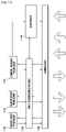
- FIG. 2 is a diagram illustrating a protocol stack of a mobile communication system according to an exemplary embodiment of the present invention.
- the protocol stack of the LTE system includes Packet Data Convergence Protocol (PDCP) 205 and 240, Radio Link Control (RLC) 210 and 235, Medium Access Control (MAC) 215 and 230, and Physical (PHY) 220 and 225.
- the PDCP 205 and 240 is responsible for IP header compression/decompression.
- the RLC 210 and 235 is responsible for segmenting the PDCP Protocol Data Unit (PDU) into segments of appropriate size for an Automatic Repeat Request (ARQ) operation.
- the MAC 215 and 230 is responsible for establishing connection to a plurality of RLC entities so as to multiplex the RLC PDUs into MAC PDUs and demultiplex the MAC PDUs into RLC PDUs.
- the PHY 220 and 225 performs channel coding on the MAC PDU and modulates the MAC PDU into OFDM symbols to transmit over radio channel or performs demodulating and channel-decoding on the received OFDM symbols and delivers the decoded data to the higher layer.
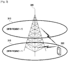
- FIG. 3 is a diagram illustrating an exemplary situation of Carrier Aggregation in a mobile communication system according to an exemplary embodiment of the present invention.
- an eNB can use multiple carriers transmitted and received in different frequency bands.
- the eNB 305 can be configured to use the carrier 315 with center frequency f1 and the carrier 310 with center frequency f3.
- the UE 330 has to transmit/receive data using one of the carriers 310 and 315.
- the UE 330 having the Carrier Aggregation capability can transmit/receive data using both the carriers 310 and 315.
- the eNB can increase the amount of the resource to be allocated to the UE having the Carrier Aggregation capability in adaptation to the channel condition of the UE so as to improve the data rate of the UE.
- the Carrier Aggregation can be understood as though the UE communicates data via multiple cells. With the use of Carrier Aggregation, the maximum data rate increases in proportion to the number of aggregated carriers.
- the phrase "the UE receives data through a certain downlink carrier or transmits data through a certain uplink carrier” refers to transmission or receipt of data through control and data channels provided in a cell corresponding to center frequencies and frequency bands of the downlink and uplink carriers.
- the Carrier Aggregation is expressed as a procedure of configuring a plurality of serving cells with the terms such as primary serving cell, secondary serving cell, and activated service cell. These terms are used with the meanings as specified in TS 36.331 and TS 36.321 released on December 2011.
- the UE's available transmit power amount is referred to as Power Headroom (PH) which is defined as the difference between a configured maximum UE output power (PCMAX) and a transmit power currently being used by the UE. If a specific condition is satisfied, the UE reports PH to the eNB. The process of the UE reporting PH to the eNB is referred as a Power Headroom Report (PHR).
- PHR Power Headroom Report
- the PHR is triggered when pathloss variation is greater than a predetermined threshold value or when a PHR period arrives.
- the eNB can predict the channel state of the eNB based on the collected PH values to determine whether to allocate an additional radio resource.
- the eNB's PH variation detection failure causes unfair resource allocation.
- FIG. 4 is a diagram illustrating transmit power configuration caused by unfair scheduling in a method according to the related art.
- Reference number 400 denotes the UE's power usage.
- the configured maximum UE output power P CMAX 410 is a value set between the upper bound P CMAX_H 405 and a lower bound P CMAX_L 415 based on the parameters provided by the eNB and predetermined parameters.
- MCS Modulation and Coding Scheme
- the used power 420 is very low as compared to the configured maximum UE output power. If a specific condition is satisfied, then the UE reports to the eNB the PH 445, (i.e., the difference between the configured maximum UE output power and the used power 420).
- the eNB determines that the configured maximum UE output power is not short even though much of the radio resource is allocated to the UE, based on the PH. In order to provide the service at higher data rate, the eNB further allocates y RBs to the UE with a higher MCS level of n. However, the configured maximum UE output power P CMAX 440 decreases while the used power 435 increases such that P CMAX 440 becomes less than the used power 435 at time t2. As an example, the used power 435 at time t2 is also greater than the lower bound P CMAX_L 450.
- the configured maximum UE output power P CMAX 440 is a value set between the upper bound P CMAX_H 430 and a lower bound P CMAX_L 450 based on the parameters provided by the eNB and predetermined parameters.
- the P CMAX 440 becomes less than the used power 435 at time t2 because the configured maximum UE output power 440 has changed according to the variations of number and locations of scheduled Physical Resource Blocks (PRBs), system bandwidth, frequency band, and number of scheduled carriers.
- PRBs Physical Resource Blocks
- This problem can be solved in such a manner that the UE reports the PH and configured maximum UE output power to the eNB at an appropriate time point such that the eNB performs uplink scheduling on the UE in consideration of the time-varying configured maximum UE output power.
- One of the factors influencing the P CMAX is Power Management Maximum Power Reduction (P-MPR).
- P-MPR Power Management Maximum Power Reduction
- Exemplary embodiments of the present invention provide a method and apparatus for reporting to the eNB whether the P-MPR is changed at an appropriate time point.
- the UE may determine P CMAX within the bounds provided in Equations 1, 2, and 3.
- P CMAX _ L MIN P EMAX ⁇ T C
- P CMAX _ H MIN P EMAX P PowerClass
- P EMAX is maximum allowed UE output power in, for example, SystemInformation-BlockType1 (SIB1) broadcasted by the eNB.
- P PowerClass is maximum UE power specified without taking into account the tolerance.
- P CMAX_H is defined as the minimum value between P EMAX and P PowerClass .
- P CMAX_L is somewhat complex.
- P CMAX_L is influenced by MPR+A-MPR and P-MPR.
- TC, MPR, and A-MPR are the parameters for defining the ceiling value to adjust maximum UE transmission power on the serving cell such that the unintended radiation or interference to adjacent channel meet to a predetermined requirement.
- MPR is the value determined according to the amount of transmission resource allocated to the UE and modulation scheme.
- A-MPR is the value determined according to uplink frequency band, geographical characteristic, and uplink transmission bandwidth. A-MPR is used for the case of frequency band particularly sensitive to ambient spurious radiation.
- ⁇ T C is the parameter for allowing additional transmission power adjustment in case where uplink transmission is performed at an edge of the frequency band. For example, if uplink transmission is performs on the lowest 4MHz or the highest 4MHz of a certain frequency band, the UE sets ⁇ T C to 1.5 dB and, otherwise, UE sets ⁇ T C to 0.
- P-MPR is a maximum power reduction value applied for satisfying Specific Absorption Rate (SAR) requirement and is determined in consideration of the distance between the device and human body. For example, if the distance between the device and human body is short, then the total transmission power value of the UE should decrease and, for this, a high value of P-MPR is applied. In contrast, if the distance between the device and the human body is long, then it is tolerable to increase the total transmit power value of the device such that P-MPR is set to a low value.
- P-MPR is associated with the power control such that when multiple carriers are used or data transmission is performed along with other system modem the maximum power allocated per carrier or system is restricted. Such influence is reflected to P-MPR.
- the configured maximum UE output power P CMAX is mainly influenced by two factors.
- the configured maximum UE output power P CMAX may be mainly influenced by the MPR+A-MPR related to the out-of-band emission requirement, and by the P-MPR related to the power management. Because the eNB cannot predict the variation of P-MPR, the UE reports, when detecting variation of P-MPR over a predetermined threshold, the PH variation amount (or PH) to the eNB. Also, because only the PH is not enough for determining the power actually used by the UE, the UE reports the configured maximum UE output power too.
- the eNB can observe the variation of the configured maximum UE output power and record the result in a database to remove the influence of the P-MPR.
- FIG. 5 is a signaling diagram illustrating a Power Headroom Report (PHR) procedure according to an exemplary embodiment of the present invention.
- PHR Power Headroom Report
- the eNB 510 firsts configures the UE in consideration of the UE capability and network status at step 515. At this time the eNB 510 can configure Carrier Aggregation (CA) and PHR of the UE 505. If multiple uplink carriers are configured for the eNB 505 (i.e., if multiple serving cells having uplink resources are configured), then the eNB 510 can configure the UE to use an extended PHR function or an extended PHR MAC CE. In order to configure the extended PHR, the eNB 510 provides the information related to PHR as follows:
- the UE 505 Upon receipt of the control message, the UE 505 configures downlink and uplink and continues normal operations according to the instruction from the eNB 510.
- the UE 505 is allocated transmission resource for new uplink transmission at step 520 and determines whether PHR condition is satisfied at step 525.
- the PHR condition is fulfilled in the following cases:
- FIG. 6 is a diagram is a diagram illustrating a Power Headroom Report (PHR) triggered by variation of a Power Management Maximum Power Reduction (P-MPR) in the Power Headroom Report method according to an exemplary embodiment of the present invention.
- PHR Power Headroom Report
- P-MPR Power Management Maximum Power Reduction
- the UE performs power reduction or power backoff, and the power reduction amount is determined according to the parameters such as MPR, A-MPR, and P-MPR.
- the parameters related to the power reduction in a certain service cell change according to whether uplink transmission takes place actually on the serving cell.
- the various transmit power parameters including P-MPR are set to 0.
- the power backoff value is determined in consideration of P-MPR satisfying the SAR requirement.
- PHR the UE reports PH and P CMAX in all of the activated serving cells with configured uplinks at the corresponding time point. Accordingly, even though no actual uplink transmission takes place in a serving cell at the time when generating PHR, P-MPR is determined.
- the P-MPR is not an actual P-MPR but a predetermined value (i.e., 0).
- PHR By taking an example of PHR at certain time points A 605 and B 610, suppose a situation in which an actual transmission takes place at a time point A as denoted by reference number 625 and no actual transmission at a time point B in a certain serving cell.
- the real P-MPR is applied at the time point A while the P-MPR set to 0 is applied at the time point B such that, although the transmit power reduction related to the real P-MPR is tiny (i.e., although the transmission power reduction value related to P-MPR is not changed nearly if actual uplink transmission takes place at the time point B in the corresponding serving cell), the UE can determine that arithmetic variations of P-MPR is equal to or greater than a predetermined threshold. As a consequence, PHR is transmitted unnecessarily.
- PHR is triggered in consideration of the variation amount of the transmit power reduction related to P-MPR.
- PHR is triggered in consideration of the variation amount of the transmit power reduction related to P-MPR only when the actual transmission takes place at both the two time points (i.e., A and B as denoted by reference number 630).
- the UE 505 If the PHR condition is fulfilled, the UE 505 generates a PHR MAC CE at step 530. Because the UE is instructed to use extended PHR MAC CE in PHR configuration process, the UE calculates PH per serving cell using Equation 4 in consideration of the P CMAX,c and required transmit power of the activated serving cells and configured to have uplink.
- PH i P CMAX , c i ⁇ 10 log 10 M PUSCH , c i + P O _ PUSCH , c j + ⁇ c j ⁇ PL c + ⁇ TF , c i + ⁇ c i
- PH(i) of i th subframe in serving cell c is calculated based on the power offset ⁇ T F,c derived from MCS, pathloss PL c , and accumulated Transmit Power Controls (TPCs) f c (i).
- PLc denotes the path loss of the cell configured to provide the pathloss for the serving cell c.
- the pathloss used for determining uplink transmit power of a certain serving cell is the pathloss of the uplink channel of the corresponding cell or the path loss of the downlink channel of another cell.
- the eNB selects the pathloss to be used and notifies the UE of the selected pathloss in the call setup process.
- fc(i) is the accumulated value of the Transmit Power Control (TPC) on the serving cell c.
- PO_PUSCH,C denotes a parameter of higher layer as sum of cell-specific and UE-specific values.
- PO_PUSCH,C has a value determined according to the type of Physical Uplink Shared Channel (PUSCH) such as semi-persistent scheduling, dynamic scheduling, and random access response.
- PUSCH Physical Uplink Shared Channel
- PH is calculated with P CMAX,c determined with zero transmit power reduction and the required transmit power using predetermined values of M PUSCH,c (i) and ⁇ TF,c (e.g., a value indicating the lowest MCS level and 1 transport block).
- the UE inserts the PH and other information per serving cell in the extended PHR MAC CE.
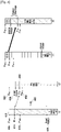
- FIG. 7 is a diagram illustrating a structure of an extended Power Headroom Report (PHR) Medium Access Control (MAC) Control Element (CE) for use in a Power Headroom Report (PHR) method according to an aspect.
- PHR Power Headroom Report
- MAC Medium Access Control
- CE Control Element
- reference numbers 700 to 730 denote a bitmap indicating PHs for the serving cells that are included in the corresponding PHR. Each bit of the bitmap corresponds to SCell index indicating a SCell.
- Reference number 750 denotes a P bit indicating whether the configured maximum UE output power P CMAX is influenced by the P-MPR according to an exemplary embodiment of the present invention.
- the eNB can trigger PHR to acquire pathloss on a specific uplink carrier.
- a PHR trigger can be implemented by defining a transmission format (transmission resource amount and MCS level) for use in PH calculation.
- the eNB In order to interpret the reported PHs correctly, the eNB has to know whether the per-cell PH included in the PHR is calculated in consideration of real PUSCH transmission or using a predetermined transmission format.
- Reference number 740 denotes a V bit which is 1-bit indicator for indicating whether the PH is calculated in consideration of real PUSCH transmission.
- a predetermined value e.g., 0
- Reference numbers 745 and 755 are PH and P CMAX respectively.
- the PHs for the individual carriers are arranged in unit of byte in ascending order of index (i.e., type 2 PH and P CMAX for PCell, type 1 PH 760 and P CMAX 765 for PCell, PH 770 and P CMAX 775 for SCell having the lowest index, PH and P CMAX for SCell having the second lowest index, PH and P CMAX for SCell having the third lowest index, and PH and P CMAX for SCell having the fourth lowest index).
- the type 2 PH is reported only for the PCell and calculated in consideration of PUCCH requirement transmit power as well as PUSCH requirement transmit power.
- Reference number 407 denotes an R bit indicating reserved bit.
- the UE At step 535, the UE generates a MAC PDU, multiplexes the PHR MAC CE in the MAC PDU.
- the UE transmits the MAC PDU to the eNB at step 540.
- the UE records the information on the pathloss, PCMAX, P-MPR, and whether the PH is calculated in consideration of real data transmission that are applied in PH calculation per serving cell.
- the eNB checks the per-serving cell PHs, whether P-MPR is applied or not, and whether PH variation is caused by P-MPR variation, and allocates uplink transmission resource in consideration of the check result.
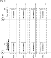
- FIG. 8 is a flowchart illustrating a Power Headroom Report (PHR) method according to an exemplary embodiment of the present invention.
- PHR Power Headroom Report
- the UE receives a control message and configures Carrier Aggregation and extended PHR according to the information carried in the control message at step 805.
- the control message includes the control information such as phr-config and extendedPHR. Afterward, the UE performs normal follow-up operation.
- the UE is allocated uplink transmission resource for new uplink transmission at step 810 and calculates uplink transmit power at step 815.
- the uplink transmission power is calculated per serving cell.
- the UE determines P CMAX,c per serving cell using Equations 1, 2, and 3 and determines the required transmit power by referencing a number of transmission resource blocks, transmission format, and pathloss. Next, the UE selects minimum value between the two values as the transmit power for the corresponding serving cell.
- the UE determines whether PHR is triggered at step 820.
- the PHR is triggered when the periodic PHR-Timer expires or the change of uplink pathloss in the service cell in active state and proving pathloss is greater than a dl-PathlossChange as compared to the previous PHR report. If P-MPR greater than 0 is currently applied or applied in the last PHR transmission, and if one of the following PHR trigger conditions are fulfilled, then PHR is triggered. If the P-MPR greater than 0 is applied, then it is necessary to adjust the LTE transmit power due to the uplink transmission by other radio transmission modem.
- the PHR trigger conditions include:
- the required power backoff controlled (or allowed) by P-MPR means the power backoff to be applied by the UE when only the SAR requirement is considered.
- the required power backoff controlled by P-MPR may differ from the real power backoff applied. For example, if the power backoff to be applied for fulfilling the neighbor channel interference restriction requirement such as MPR and A-MPR at a certain time point is A dB and the power backoff to be applied for fulfilling SAR requirement is B dB, then the required power backoff controlled by P-MPR is B dB.
- the real power backoff applied by the UE is determined by the maximum value between A and B.
- the UE calculates PH per serving cell using Equation 4 in consideration of the PCMAX,c and required transmit power on the activated serving cells with configured uplink at step 825.
- the UE generates the extended PHR MAC CE with per-serving cell PHs and other information as shown in FIG. 7 .
- the UE sets P bit to a corresponding value at step 830.
- the P bit is a 1-bit indicator for indicating whether which of P-MPR and MPR+A-MPR has contributed to the calculation of P CMAX,c per serving cell.
- the P-bit set to 0 if the maximum transmit power is not influenced by P-MPR for power management, and the P-bit is set to 1 if the maximum transmit power is influenced by P-MPR. That is, the P bit is set to 1 if P CMAX,c has a different value due to the influence of P-MPR, and the P-bit is set to 0 if P CMAX,c has the same value regardless of whether P-MPR is applied or not.
- the UE generates and transmits a MAC PDU at step 835. Afterward, the UE waits for allocation of new uplink transmission resource.
- the MAC PDU can include the PHR MAC CE.
- PHR MAC CE can be categorized into one of two categories: normal PHR MAC CE and extended PHR MAC CE.
- the normal PHR MAC CE is the PHR MAC CE used before the introduction of Carrier Aggregation
- the extended PHR MAC CE is the PHR MAC CE introduced for transmitting PHs and supplementary information on multiple serving cells.
- the normal PHR MAC CE is composed of 2 reserved bits and 6-bit PH field.
- the extended MAC CE format is depicted in FIG. 7 .
- the network can instruct the UE to use the normal PHR MAC CE or extended PHR MAC CE in consideration of the UE capability and current configuration or network state. This can be done by sending the UE the control information of MAC-MainConfig including the information indicating the use of extended PHR MAC CE (hereinafter, referred to as extendedPHR). This information can indicate one of the four cases determined according to the PHR MAC CE format and whether to use Carrier Aggregation as follows:
- the case (2) has no special usefulness but requires determining which type of PH should be inserted for which serving cell in the normal PHR MAC CE, resulting in increase of UE implementation complexity. In an example, the case (2) is excluded to reduce UE implementation complexity.
- the type 2 PH field of the PHR MAC CE should be filled with, for example, meaningless information.
- the UE is configured to use the extended PHR MAC CE format having the type 2 PH field when the UE is configured to support simultaneous transmission of PUCCH and PUSCH, and the UE is configured to use the extended PHR MAC CE format having no type 2 PH field when the UE is configured not to support simultaneous transmission of PUCCH and PUSCH.
- the network instructs the UE to use one of the normal and extended PHR MAC CE according to the UE capability and according to the current configuration or network state.
- FIG. 9 is a flowchart illustrating a Power Headroom Report method according to an an aspect.
- the UE first receives the control information referred as MAC-MainConfig from the eNB at step 905.
- This control information is transmitted to the UE in RRC CONNECTION SETUP message or RRC CONNECTION RECONFIGURATION message.
- This control information includes configuration information related to the MAC layer functionality such as phr-Config as information related to PHR configuration and extendedPHR.
- the UE determines whether the MAC-MainConfig includes extendedPHR (or whether the control message received at step 905 includes extendedPHR information) at step 910 and, if so, the procedure proceeds to step 915 and, otherwise the procedure proceeds to step 935. If this information includes the indicator indicating the use of PHR MAC CE format, such information means to instruct the UE to use the extended PHR MAC CE and, otherwise, the UE is instructed to use the normal PHR MAC CE.
- the UE determines whether the most recently received MAC-MainConfig (or a most recently received control message, e.g., RRC CONNECTION SETUP message or RRC CONNECTION RECONFIGURATION message) includes extendedPHR. If it is determined that the extendedPHR is included at step 915, then the procedure proceeds to step 930 and, otherwise, the procedure proceeds to step 920. If the most recently received MAC-MainConfig information includes no extendedPHR, then this means that the normal PHR MAC CE is recommended.
- a most recently received control message e.g., RRC CONNECTION SETUP message or RRC CONNECTION RECONFIGURATION message
- the procedure proceeds to step 920, this means that the PHR MAC CE format is changed for the normal PHR MAC CE format.
- the UE triggers PHR and generates PHR MAC CE in extended format when the uplink transmission resource for new transmission is available at step 920.
- the UE determines whether to include type 2 PH according to whether simultaneous PUSCH and PUCCH transmission is configured. If the simultaneous PUSCH and PUCCH transmission is configured, the UE includes the type 2 PH in the extended PHR MAC CE and, otherwise, the UE excludes the type 2 PH.
- the UE transmits the extended PHR MAC CE at step 925 and terminates the procedure.
- the PHR MAC CE generation procedure corresponds to step 825 of FIG. 8 .
- the UE determines whether there are multiple serving cells with uplink carrier configuration at step 935. If there are multiple serving cells with uplink carrier configuration, then the procedure proceeds to step 940. If there are not multiple serving cells with uplink carrier configuration, then the procedure proceeds to step 945.
- the multiple serving cells can be configured with uplink carriers according to the information of the RRC Control message including MAC-MainConfig or has been configured with uplink carriers already before receiving the RRC control message.
- step 940 this means that the UE has received the command for use of normal PHR MAC CE although multiple cells are configured with uplink carriers. Accordingly, the UE determines occurrence of unexpected error and ignores the information to maintain the normal PHR MAC CE formation at step 940. However, the UE processes other control information included in the RRC control message normally with the exception of the erroneous information.
- the UE determines whether the most lately received MAC-MainConfig includes extendedPHR at step 945 and, if so, the procedure proceeds to step 955 and, otherwise, the procedure proceeds to step 950.
- the procedure proceeds to step 955, this means that the PHR MAC CE format is changed from extended PHR MAC CE formation to normal PHR MAC CE format. Accordingly, the UE triggers PHR with the normal PHR MAC CE format when the uplink resource for new transmission is available. If the simultaneous PUSCH and PUCCH transmission is configured, the UE selects and includes the type 1 PH in the PH field. Otherwise, if the simultaneous PUSCH and PUCCH transmission is not configured, this means that type 2 PH is out of consideration and thus there is no need for selection. The UE calculates the type 1 PH for the primary serving cell and includes the type 1 PH in the PH field of the normal PHR MAC CE format. Finally, the UE transmits the PHR MAC CE to the eNB at step 960 and terminates the procedure.
- the type 1 PH is determined in consideration of the PUSCH transmit power
- type 2 PH is determined in consideration of both the PUSCH and PUCCH transmission powers.
- the P bit is the first bit of PH byte (e.g., a byte having PH field).
- the present description includes a method for setting the first bit according to the PHR MAC CE format which is currently used by the UE. If the currently used PHR MAC CE format is the normal PHR MAC CE format, the UE sets the first bit to 0 even though the condition for setting the P bit to 1 is satisfied. This is because if the eNB receiving the PHR in normal format is a legacy eNB, then it is expected that the first bit of the PH byte is set to 0 such that, if this bit is set to 1, then the eNB is likely to malfunction. Otherwise, if the PHR MAC CE format is the extended PHR MAC CE format, this means that the eNB is of interpreting the P bit correctly such that UE sets the P bit normally.
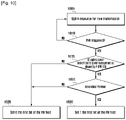
- FIG. 10 is a flowchart illustrating a Power Headroom Report (PHR) method according to an aspect.
- PHR Power Headroom Report
- the UE is allocated uplink resource for new transmission at step 1005 and determines whether PHR is triggered at step 1010.
- the UE operation at step 1010 is identical with the operation at step 820 of FIG. 8 .
- step 1010 the UE waits for allocation of uplink resource for new transmission while performing normal operation. If PHR is triggered at step 1010, then the procedure proceeds to step 1015.
- step 1015 the UE determines whether power backoff due to power management as allowed by P-MPR is applied for calculating PH or P CMAX,c . In more detail, the UE determines whether the maximum transmit power is influenced by the P-MPR for power management. For example, the UE determines whether the PCMAX,c is changed to a different value by the P-MPR for power management. If it is determined that the power backoff due to power management as allowed by P-MPR is not applied for calculating PH or P CMAX,c , then the procedure proceeds to step 1025. Otherwise, the procedure proceeds to step 1020.
- the UE determines whether the current PHR MAC CE format is the extended PHR MAC CE format. In other words, the UE determines whether the most lately received MAC-MainConfig includes extendedPHR and, if so, the procedure proceeds to step 1030 and, otherwise, step 1025.
- the UE set the first bit of the PH byte to 1 (i.e. sets the P bit to 1) and transmits the PHR MAC CE.
- the UE sets the first bit of the PH byte to 0 (i.e., sets the P bit to 0) and transmits the PHR MAC CE.
- FIG. 11 is a block diagram illustrating a configuration of an User Equipment (UE) according to an an aspect.
- UE User Equipment
- the UE includes a transceiver 1105, a controller 1110, a multiplexer/demultiplexer1120, a control message processor 1135, and higher layer processors 1125 and 1130.
- the transceiver 1105 receives data and control signal on the downlink channel, and transmits data and control signal on the uplink channel in a serving cell. If multiple serving cells are configured, the transceiver 1105 transmits and receives data and control signals in the multiple serving cells.
- the multiplexer/demultiplexer 1102 multiplexes the data generated by the higher layer processors 1125 and the control message processor 1135, and demultiplexes the data received by the transceiver and delivers the demultiplexed data to the higher layer processor 1125 and 1130 and/or the control message processor 1135.
- the control message processor 1135 processes the control message received from the eNB and takes an appropriate action. That is, the control message processor 1135 is responsible for configuring PHR function by referencing the control information such as MAC-MainConfig included in the RRC control message.
- Each of the higher layer processors 1125 and 1130 is configured per service and processes the data generated in association with the user service such as File Transfer Protocol (FTP) and Voice over Internet Protocol (VoIP) to the multiplexer/demultiplexer 1120 or processes the data from the multiplexer/demultiplexer 1120 to the higher layer service application.
- FTP File Transfer Protocol
- VoIP Voice over Internet Protocol
- the controller 1110 checks the scheduling command (e.g. uplink grants) received through the transceiver 1105, and controls the transceiver 1105 and multiplexer/demultiplexer 1120 to perform uplink transmission with appropriate transmission resource at appropriate timing.
- the controller 1110 calculates uplink transmit power per cell, determines whether to trigger PHR, and set P bit.
- the controller 1110 the multiplexer/demultiplexer 1120, the control message processor 1135, and higher layer processors 1125 and 1130 are implemented as separate function blocks responsible for different functions for convenience of technical explanation, the UE is not limited to this configuration.
- the functions of the multiplexer/demultiplexer 1120, the control message processor 1135, and the higher layer processors 1125 and 1130 can be performed by the controller 1110.
- the Power Headroom Report method and apparatus of the exemplary embodiments of the present invention is advantageous to report the UE's Power Headroom per cell efficiently in the system operating in Carrier Aggregation mode.
Claims (12)
- Verfahren, das von einem Endgerät in einem drahtlosen Kommunikationssystem ausgeführt wird, wobei das Verfahren Folgendes umfasst:Bestimmen, ob ein erster Leistungsspielraumbericht, PHR, ausgelöst werden soll;Erzeugen (825) des ersten PHR, falls der erste PHR ausgelöst wird; undÜbertragen (835) des ersten PHR an eine Basisstation,wobei das Bestimmen, ob der erste PHR ausgelöst werden soll, Folgendes umfasst:Bestimmen (810), dass es für eine Übertragung auf einer Bedienzelle zu einem ersten Zeitpunkt (610) zugewiesene Uplink(UL)-Ressourcen gibt;Bestimmen (820), ob sich das Leistungs-Backoff aufgrund der Leistungsverwaltung auf der Bedienzelle um mehr als einen Schwellenwert seit einer letzten Übertragung (630) eines zweiten PHR auf der Bedienzelle zu einem zweiten Zeitpunkt (605) geändert hat, als das Endgerät für eine Übertragung auf der Bedienzelle zugewiesene UL-Ressourcen hatte; undBestimmen, dass der erste PHR ausgelöst wird, falls sich das Leistungs-Backoff aufgrund der Leistungsverwaltung auf der Bedienzelle um mehr als einen Schwellenwert seit der letzten Übertragung (630) des zweiten PHR auf der Bedienzelle zu dem zweiten Zeitpunkt (605) geändert hat, als das Endgerät für die Übertragung auf der Bedienzelle zugewiesene UL-Ressourcen hatte.
- Verfahren nach Anspruch 1, wobei der erste PHR und der zweite PHR unter Verwenden eines erweiterten Leistungsspielraum-Medium Access Control-Elements, PH MAC CE, übertragen werden.
- Verfahren nach Anspruch 2, wobei ein erstes Bit eines Oktetts, das ein Leistungsspielraum(PH)-Feld in dem erweiterten PH MAC CE enthält, auf 1 gesetzt wird, falls das Leistungs-Backoff aufgrund der Leistungsverwaltung angewendet wird.
- Verfahren, das von einem drahtlosen Kommunikationssystem ausgeführt wird, wobei das Verfahren Folgendes umfasst:Übertragen von Konfigurationsinformationen durch eine Basisstation an ein Endgerät;Bestimmen durch das Endgerät, ob ein erster Leistungsspielraumbericht, PHR, ausgelöst werden soll;Erzeugen (825) des ersten PHR durch das Endgerät, falls der erste PHR ausgelöst wird; undÜbertragen (835) des ersten PHR unter Verwenden der Konfigurationsinformationen durch das Endgerät an die Basisstation,wobei das Bestimmen, ob der erste PHR ausgelöst werden soll, Folgendes umfasst:Bestimmen (810) durch das Endgerät, dass es für eine Übertragung auf einer Bedienzelle zu einem ersten Zeitpunkt (610) zugewiesene Uplink(UL)-Ressourcen gibt;Bestimmen (820) durch das Endgerät, ob sich das Leistungs-Backoff aufgrund der Leistungsverwaltung auf der Bedienzelle um mehr als einen Schwellenwert seit einer letzten Übertragung (630) eines zweiten PHR auf der Bedienzelle zu einem zweiten Zeitpunkt (605) geändert hat, als das Endgerät für eine Übertragung auf der Bedienzelle zugewiesene UL-Ressourcen hatte; undBestimmen durch das Endgerät, dass der erste PHR ausgelöst wird, falls sich das Leistungs-Backoff aufgrund der Leistungsverwaltung auf der Bedienzelle um mehr als den Schwellenwert seit der letzten Übertragung (630) des zweiten PHR auf der Bedienzelle zu dem zweiten Zeitpunkt (605) geändert hat, als das Endgerät für die Übertragung auf der Bedienzelle zugewiesene UL-Ressourcen hatte.
- Verfahren nach Anspruch 4, wobei der erste PHR und der zweite PHR von dem Endgerät an die Basisstation unter Verwenden eines erweiterten Leistungsspielraum-Medium Access Control-Elements, PH MAC CE, übertragen werden.
- Verfahren nach Anspruch 5, wobei ein erstes Bit eines Oktetts, das ein Leistungsspielraum(PH)-Feld in dem erweiterten PH MAC CE enthält, auf 1 gesetzt wird, falls das Leistungs-Backoff aufgrund der Leistungsverwaltung angewendet wird.
- Endgerät eines drahtlosen Kommunikationssystems, wobei das Endgerät Folgendes umfasst:einen Transceiver; undeine Steuerung, die mit dem Transceiver gekoppelt und konfiguriert ist zum:Bestimmen, ob ein erster Leistungsspielraumbericht, PHR, ausgelöst werden soll;Erzeugen (825) des ersten PHR, falls der erste PHR ausgelöst wird; undÜbertragen (835) des ersten PHR an eine Basisstation, wobei, um zu bestimmen, ob der erste PHR ausgelöst werden soll, die Steuerung ferner konfiguriert ist zum:Bestimmen (810), dass es für eine Übertragung auf einer Bedienzelle zu einem ersten Zeitpunkt (610) zugewiesene Uplink(UL)-Ressourcen gibt,Bestimmen (820), ob sich das Leistungs-Backoff aufgrund der Leistungsverwaltung auf der Bedienzelle um mehr als einen Schwellenwert seit einer letzten Übertragung (630) eines zweiten PHR auf der Bedienzelle zu einem zweiten Zeitpunkt (605) geändert hat, als das Endgerät für eine Übertragung auf der Bedienzelle zugewiesene UL-Ressourcen hatte, undBestimmen, dass der erste PHR ausgelöst wird, falls sich das Leistungs-Backoff aufgrund der Leistungsverwaltung auf der Bedienzelle um mehr als den Schwellenwert seit der letzten Übertragung (630) des zweiten PHR auf der Bedienzelle zu dem zweiten Zeitpunkt (605) geändert hat, als das Endgerät für die Übertragung auf der Bedienzelle zugewiesene UL-Ressourcen hatte.
- Endgerät nach Anspruch 7, wobei das Endgerät ferner konfiguriert ist, um den ersten PHR und den zweiten PHR unter Verwenden eines erweiterten Leistungsspielraum-Medium Access Control-Elements, PH MAC CE, zu übertragen.
- Endgerät nach Anspruch 8, wobei das Endgerät ferner konfiguriert ist, um ein erstes Bit eines Oktetts, das ein Leistungsspielraum(PH)-Feld in dem erweiterten PH MAC CE enthält, auf 1 zu setzen, falls das Leistungs-Backoff aufgrund der Leistungsverwaltung angewendet wird.
- Drahtloses Kommunikationssystem, das eine Basisstation und ein Endgerät umfasst, wobei die Basisstation Folgendes umfasst:einen Transceiver; undeine Steuerung, die mit dem Transceiver gekoppelt und konfiguriert ist zum:Übertragen von Konfigurationsinformationen an das Endgerät, undwobei das Endgerät Folgendes umfasst:einen Transceiver; undeine Steuerung, die mit dem Transceiver gekoppelt und konfiguriert ist zum:Bestimmen, ob ein erster Leistungsspielraumbericht, PHR, ausgelöst werden soll;Erzeugen (825) des ersten PHR, falls der erste PHR ausgelöst wird; undÜbertragen des ersten PHR unter Verwenden der Konfigurationsinformationen an die Basisstation,wobei, um zu bestimmen, ob der erste PHR ausgelöst werden soll, die Steuerung ferner konfiguriert ist zum:Bestimmen (810), dass es für eine Übertragung auf einer Bedienzelle zu einem ersten Zeitpunkt (610) zugewiesene UL-Ressourcen gibt,Bestimmen (820), ob sich das Leistungs-Backoff aufgrund der Leistungsverwaltung auf der Bedienzelle um mehr als einen Schwellenwert seit einer letzten Übertragung (630) eines zweiten PHR auf der Bedienzelle zu einem zweiten Zeitpunkt (605) geändert hat, als das Endgerät für eine Übertragung auf der Bedienzelle zugewiesene UL-Ressourcen hatte, undBestimmen, dass der erste PHR ausgelöst wird, falls sich das Leistungs-Backoff aufgrund der Leistungsverwaltung auf der Bedienzelle um mehr als den Schwellenwert seit der letzten Übertragung (630) des zweiten PHR auf der Bedienzelle zu dem zweiten Zeitpunkt (605) geändert hat, als das Endgerät für die Übertragung auf der Bedienzelle zugewiesene UL-Ressourcen hatte.
- System nach Anspruch 10, wobei das Endgerät ferner konfiguriert ist, um den ersten PHR und den zweiten PHR von dem Endgerät an die Basisstation unter Verwenden eines erweiterten Leistungsspielraum-Medium Access Control-Elements, PH MAC CE, zu übertragen.
- System nach Anspruch 11, wobei das Endgerät ferner konfiguriert ist, um ein erstes Bit eines Oktetts, das ein Leistungsspielraum(PH)-Feld in dem erweiterten PH MAC CE enthält, auf 1 zu setzen, falls das Leistungs-Backoff aufgrund der Leistungsverwaltung angewendet wird.
Applications Claiming Priority (5)
| Application Number | Priority Date | Filing Date | Title |
|---|---|---|---|
| US201161442985P | 2011-02-15 | 2011-02-15 | |
| US201161444844P | 2011-02-21 | 2011-02-21 | |
| US201161471872P | 2011-04-05 | 2011-04-05 | |
| US201161481878P | 2011-05-03 | 2011-05-03 | |
| PCT/KR2012/001147 WO2012111980A2 (en) | 2011-02-15 | 2012-02-15 | Power headroom report method and apparatus of ue priority |
Publications (3)
| Publication Number | Publication Date |
|---|---|
| EP2676475A2 EP2676475A2 (de) | 2013-12-25 |
| EP2676475A4 EP2676475A4 (de) | 2016-11-02 |
| EP2676475B1 true EP2676475B1 (de) | 2022-04-06 |
Family
ID=79019363
Family Applications (1)
| Application Number | Title | Priority Date | Filing Date |
|---|---|---|---|
| EP12747557.2A Active EP2676475B1 (de) | 2011-02-15 | 2012-02-15 | Leistungsreservebericht |
Country Status (3)
| Country | Link |
|---|---|
| US (1) | US11943721B2 (de) |
| EP (1) | EP2676475B1 (de) |
| CN (1) | CN107613523B (de) |
Families Citing this family (5)
| Publication number | Priority date | Publication date | Assignee | Title |
|---|---|---|---|---|
| CN111386725B (zh) | 2017-09-28 | 2023-03-21 | 三星电子株式会社 | 用于在无线通信系统中处理pdcp操作的方法和系统 |
| CN112398595A (zh) * | 2019-08-16 | 2021-02-23 | 索尼公司 | 电子设备、无线通信方法和计算机可读存储介质 |
| CN112867057B (zh) * | 2019-11-08 | 2024-03-08 | 荣耀终端有限公司 | 一种数据传输方法及装置 |
| US20230208569A1 (en) * | 2021-12-29 | 2023-06-29 | Qualcomm Incorporated | Semi-persistent scheduling timer for reliable transmission |
| CN116938295A (zh) * | 2022-04-02 | 2023-10-24 | 上海朗帛通信技术有限公司 | 一种被用于无线通信的通信节点中的方法和装置 |
Family Cites Families (95)
| Publication number | Priority date | Publication date | Assignee | Title |
|---|---|---|---|---|
| US8711773B2 (en) | 2008-09-05 | 2014-04-29 | Blackberry Limited | Multi-carrier operation for wireless systems |
| WO2004093476A1 (ja) | 2003-04-16 | 2004-10-28 | Nec Corporation | 移動通信システム、基地局、移動局、及びそれらに用いる無線通信方法 |
| US7184792B2 (en) | 2004-02-10 | 2007-02-27 | Qualcomm Incorporated | Delayed data transmission in a wireless communication system after physical layer reconfiguration |
| WO2007038955A1 (en) | 2005-09-30 | 2007-04-12 | Telecom Italia S.P.A. | Method for planning a cellular mobile telecommunications network |
| US8260291B2 (en) | 2005-12-26 | 2012-09-04 | Htc Corporation | Method for handling periodic PLMN search in RRC connected mode in UMTS system |
| US8089938B2 (en) | 2005-12-28 | 2012-01-03 | Alcatel Lucent | Method of synchronizing with an uplink channel and a method of determining a propagation delay in a wireless communications system |
| JP5230721B2 (ja) | 2007-03-30 | 2013-07-10 | テレコム・イタリア・エッセ・ピー・アー | 無線通信ネットワークへの移動通信端末の接続を可能にするための方法およびシステム |
| US8238281B2 (en) | 2007-04-27 | 2012-08-07 | Telefonaktiebolaget Lm Ericsson (Publ) | Method and device for saving power in a wireless user terminal |
| EP2124362B1 (de) | 2007-06-12 | 2013-09-18 | Sharp Kabushiki Kaisha | Verwendung einer region, in der normalerweise die radio-ressourcen-zuteilungs-information übermittelt wird, zur anforderung eines random-access-signals - basisstation, mobilstation und entsprechende verfahren |
| KR101514841B1 (ko) | 2007-08-10 | 2015-04-23 | 엘지전자 주식회사 | 효율적인 랜덤 액세스 재시도를 수행하는 방법 |
| KR101514079B1 (ko) | 2008-01-07 | 2015-04-21 | 엘지전자 주식회사 | 상향링크 시간 동기 타이머의 재구성 방법 |
| KR101468219B1 (ko) | 2008-01-16 | 2014-12-03 | 삼성전자주식회사 | 이동통신시스템의 버퍼상태보고 장치 및 방법 |
| US9084201B2 (en) | 2008-01-25 | 2015-07-14 | Qualcomm Incorporated | Power headroom management in wireless communication systems |
| US8243667B2 (en) | 2008-01-28 | 2012-08-14 | Lg Electronics Inc. | Method for transmitting scheduling request effectively in wireless communication system |
| KR101375936B1 (ko) | 2008-02-01 | 2014-03-18 | 엘지전자 주식회사 | 시간동기 타이머의 만료 시 하향링크 harq의 동작 방법 |
| KR101531419B1 (ko) | 2008-02-01 | 2015-06-24 | 엘지전자 주식회사 | 시간동기 타이머의 만료 시 상향링크 harq의 동작 방법 |
| KR100925333B1 (ko) | 2008-03-14 | 2009-11-04 | 엘지전자 주식회사 | 랜덤 액세스 과정에서 상향링크 동기화를 수행하는 방법 |
| US8249004B2 (en) | 2008-03-14 | 2012-08-21 | Interdigital Patent Holdings, Inc. | Coordinated uplink transmission in LTE DRX operations for a wireless transmit receive unit |
| US8320287B2 (en) | 2008-03-21 | 2012-11-27 | Research In Motion Limited | Method and system for the indication of long DRX in a wireless network |
| KR20090101793A (ko) | 2008-03-24 | 2009-09-29 | 삼성전자주식회사 | 이동 통신 시스템에서 매체 접근 제어 프로토콜 데이터유닛의 전송 성공 여부 판단 방법 및 장치 |
| ES2798599T3 (es) * | 2008-03-26 | 2020-12-11 | Vivo Mobile Communication Co Ltd | Ampliación de la notificación de informes del margen de potencia |
| EP2263341B1 (de) | 2008-04-14 | 2018-09-19 | Amazon Technologies, Inc. | Verfahren und vorrichtung zur durchürung von direktzugriffsprozeduren |
| GB2461158B (en) | 2008-06-18 | 2011-03-02 | Lg Electronics Inc | Method for performing random access procedures and terminal therof |
| JP5174554B2 (ja) | 2008-06-23 | 2013-04-03 | 株式会社エヌ・ティ・ティ・ドコモ | 移動通信方法、移動局及び無線基地局 |
| JP5107465B2 (ja) | 2008-06-30 | 2012-12-26 | インターデイジタル パテント ホールディングス インコーポレイテッド | E−UTRAN(EvolvedUniversalTerrestrialRadioAccessNetwork)においてハンドオーバーを行うための方法および装置 |
| US20100054237A1 (en) | 2008-09-04 | 2010-03-04 | Motorola, Inc. | Synchronization for femto-cell base stations |
| KR100917832B1 (ko) | 2008-09-19 | 2009-09-18 | 엘지전자 주식회사 | 시간 정렬 타이머를 고려한 신호 송수신 방법 및 이를 위한 사용자 기기 |
| US8514793B2 (en) | 2008-10-31 | 2013-08-20 | Interdigital Patent Holdings, Inc. | Method and apparatus for monitoring and processing component carriers |
| EP2371078B1 (de) | 2008-12-03 | 2017-02-08 | InterDigital Patent Holdings, Inc. | Report der aufwärtsgerichteten leistungsspanne bei trägeraggregation |
| WO2010064858A2 (en) | 2008-12-04 | 2010-06-10 | Lg Electronics Inc. | Method and apparatus for performing random access in a multi-carrier system |
| US8615230B2 (en) | 2008-12-19 | 2013-12-24 | Htc Corporation | Method of reporting radio access technology capability and related apparatus |
| KR20100073976A (ko) | 2008-12-23 | 2010-07-01 | 엘지전자 주식회사 | 상향링크 전송 전력을 제어하는 방법 및 이를 위한 장치 |
| EP3110224B1 (de) | 2009-01-08 | 2017-08-30 | LG Electronics, Inc. | Verfahren zur verarbeitung von zeitausrichtungsbefehlen während einer direktzugriffsprozedur |
| US8964659B2 (en) | 2009-02-02 | 2015-02-24 | Lg Electronics Inc. | Random access channel resource allocation |
| WO2010087569A1 (en) | 2009-02-02 | 2010-08-05 | Lg Electronics Inc. | Determination of user equipment antenna capability |
| US20110317777A1 (en) | 2009-02-18 | 2011-12-29 | Min Huang | Controlling Transmissions on Composite Carriers |
| WO2010107354A1 (en) | 2009-03-17 | 2010-09-23 | Telefonaktiebolaget L M Ericsson (Publ) | High priority random access |
| KR101568878B1 (ko) * | 2009-03-17 | 2015-11-12 | 삼성전자주식회사 | 무선 통신 시스템에서 단말의 가용 전송 전력 정보를 보고하는 방법 및 장치 |
| US8989105B2 (en) | 2009-03-17 | 2015-03-24 | Htc Corporation | Method of establishing multiple links with multiple component carriers and related communication device |
| CN101841905B (zh) | 2009-03-18 | 2012-12-26 | 电信科学技术研究院 | 一种指示重启终端时间对准定时器的方法及基站 |
| US8767585B2 (en) | 2009-04-23 | 2014-07-01 | Interdigital Patent Holdings, Inc. | Method and apparatus for random access in multicarrier wireless communications |
| EP2244515A1 (de) | 2009-04-23 | 2010-10-27 | Panasonic Corporation | Logisches Kanalpriorisierungsverfahren zur Erzeugung von mehrfachen Uplink-Transportblöcken |
| CN101873713A (zh) | 2009-04-24 | 2010-10-27 | 中兴通讯股份有限公司 | 随机接入方法、终端 |
| US20100272091A1 (en) | 2009-04-27 | 2010-10-28 | Motorola, Inc. | Uplink Scheduling Supoort in Multi-Carrier Wireless Communication Systems |
| US8437798B2 (en) | 2009-04-27 | 2013-05-07 | Motorola Mobility Llc | Uplink scheduling support in multi-carrier wireless communication systems |
| CN101883437B (zh) | 2009-05-05 | 2014-12-10 | 中兴通讯股份有限公司 | 随机接入方法以及基站 |
| CA2763448C (en) | 2009-05-22 | 2016-09-06 | Research In Motion Limited | Power headroom reporting for carrier aggregation |
| CN101932087A (zh) | 2009-06-19 | 2010-12-29 | 大唐移动通信设备有限公司 | 一种功率余量的上报方法、装置和系统 |
| US8634313B2 (en) | 2009-06-19 | 2014-01-21 | Qualcomm Incorporated | Method and apparatus that facilitates a timing alignment in a multicarrier system |
| US20110158117A1 (en) | 2009-06-29 | 2011-06-30 | Qualcomm Incorporated | Power headroom report for simultaneous transmissions on disparate radio access technologies |
| CN101998661B (zh) | 2009-08-13 | 2014-01-29 | 电信科学技术研究院 | 一种判决无线链路失败的方法和装置 |
| KR101683113B1 (ko) | 2009-08-14 | 2016-12-06 | 엘지전자 주식회사 | 상향링크 및 하향링크 멀티 캐리어를 지원하는 무선통신 시스템에 있어서, 사용자 기기와 기지국 간의 무선 통신 방법 및 상기 방법을 수행하기 위한 장치 |
| CN101998646A (zh) | 2009-08-19 | 2011-03-30 | 中兴通讯股份有限公司 | 用于长期演进系统的随机接入方法及装置 |
| CN101646234A (zh) | 2009-09-01 | 2010-02-10 | 中兴通讯股份有限公司 | 一种定时提前量的获取方法 |
| EP2635078B1 (de) | 2009-09-15 | 2018-11-07 | Huawei Technologies Co., Ltd. | Uplink-Synchronisationsverarbeitungsverfahren, Benutzergerät und Basisstation |
| WO2011035420A1 (en) | 2009-09-25 | 2011-03-31 | Research In Motion Limited | System and method for multi-carrier network operation |
| EP2317815A1 (de) | 2009-11-02 | 2011-05-04 | Panasonic Corporation | Leistungsgrenzenmeldung in einem Carrier-Aggregation-Kommunikationssystem |
| EP2502456B1 (de) | 2009-11-19 | 2020-08-12 | InterDigital Patent Holdings, Inc. | Aktivierung/deaktivierung von komponententrägern in mehrträgersystemen |
| US8315661B2 (en) | 2009-12-31 | 2012-11-20 | Cellco Partnership | Enhanced power headroom reporting |
| KR101752500B1 (ko) | 2010-01-07 | 2017-06-30 | 엘지전자 주식회사 | 무선 통신 시스템에서 시간 동기를 수신하는 방법 및 장치 |
| JP5702806B2 (ja) | 2010-01-08 | 2015-04-15 | インターデイジタル パテント ホールディングス インコーポレイテッド | 複数のアップリンクキャリアとのタイムアライメントの維持 |
| KR101803015B1 (ko) | 2010-02-10 | 2017-12-01 | 주식회사 골드피크이노베이션즈 | 다수의 요소 반송파를 운영하는 무선 통신 시스템에서 업링크 동기를 설정하는 방법 및 장치 |
| EP2534915A2 (de) | 2010-02-12 | 2012-12-19 | InterDigital Patent Holdings, Inc. | Verfahren und vorrichtung für optimierte uplink-rach-übertragung |
| CN101848506B (zh) | 2010-03-25 | 2012-10-10 | 新邮通信设备有限公司 | 一种长期演进增强系统中的切换方法和系统 |
| US9084195B2 (en) | 2010-04-01 | 2015-07-14 | Nokia Technologies Oy | Multiple timing advance and carrier aggregation |
| DK2760241T3 (en) | 2010-04-01 | 2018-09-10 | Sun Patent Trust | TRANSFER EFFECT MANAGEMENT FOR PHYSICAL DIRECT ACCESS CHANNELS |
| US9363059B2 (en) | 2010-04-02 | 2016-06-07 | Acer Incorporated | Method of handling component carrier activation and deactivation and communication device thereof |
| TWI459839B (zh) | 2010-04-02 | 2014-11-01 | Mediatek Inc | 管理多成分載波、緩存器狀態報告以及功率餘裕回報方法 |
| US8982805B2 (en) | 2010-04-09 | 2015-03-17 | Acer Incorporated | Activating component carriers by non-contention based random access procedure |
| US8867440B2 (en) | 2010-05-28 | 2014-10-21 | Qualcomm Incorporated | Power headroom reporting for multicarrier LTE systems |
| CN106912097A (zh) | 2010-06-18 | 2017-06-30 | 瑞典爱立信有限公司 | 提供以分量载波索引的顺序排列的功率上升空间报告的方法及有关无线终端和基站 |
| WO2011161014A1 (en) | 2010-06-21 | 2011-12-29 | Nokia Siemens Networks Oy | Carrier aggregation with power headroom report |
| WO2012044102A2 (en) | 2010-09-30 | 2012-04-05 | Lg Electronics Inc. | Apparatus and method of reporting power headroom in wireless communication system |
| CN105898848B (zh) | 2010-09-30 | 2019-08-06 | 索尼公司 | 电子设备、通信方法以及用户设备 |
| US8730829B2 (en) | 2010-10-01 | 2014-05-20 | Mediatek Inc. | Indication of user equipment transmit power capacilty in carrier aggregation |
| US9055544B2 (en) | 2010-11-02 | 2015-06-09 | Alcatel Lucent | Methods of setting maximum output power for user equipment and reporting power headroom, and the user equipment |
| US8989025B2 (en) | 2010-11-12 | 2015-03-24 | Telefonaktiebolaget L M Ericsson (Publ) | UE timing adjustment in a multi-RAT, carrier aggregation community system |
| JP5307112B2 (ja) | 2010-12-17 | 2013-10-02 | シャープ株式会社 | 移動局装置、基地局装置、無線通信システム、制御方法及び集積回路 |
| KR101823186B1 (ko) | 2010-12-30 | 2018-01-29 | 텔레호낙티에볼라게트 엘엠 에릭슨(피유비엘) | 통신 시스템에서 phr에 전력 백오프 표시를 가능하게 하는 방법 및 장치 |
| US8934362B2 (en) | 2011-01-06 | 2015-01-13 | Mediatek Inc. | Power control method to mitigate interference for in-device coexistence |
| WO2012094573A2 (en) | 2011-01-07 | 2012-07-12 | Interdigital Patent Holdings, Inc. | Methods, apparatus and systems for handling additional power backoff |
| KR101763751B1 (ko) | 2011-01-11 | 2017-08-02 | 삼성전자 주식회사 | 반송파 집적 기술을 사용하는 무선통신시스템에서 부차반송파의 활성화 및 비활성화 방법 및 장치 |
| WO2012108643A2 (en) | 2011-02-09 | 2012-08-16 | Pantech Co., Ltd. | Apparatus and method for transmitting uplink signal in multiple component carrier system |
| EP2679046B1 (de) | 2011-02-21 | 2018-08-15 | Samsung Electronics Co., Ltd. | Verfahren zur effizienten meldung der übertragungsleistung einer benutzervorrichtung und vorrichtung dafür |
| WO2012122170A1 (en) * | 2011-03-07 | 2012-09-13 | Interdigital Patent Holdings, Inc. | Method and apparatus for sending uplink control information for multi-radio access technology operation |
| US8923251B2 (en) | 2011-03-24 | 2014-12-30 | Htc Corporation | Method of handling uplink time alignment |
| TWI459847B (zh) | 2011-04-01 | 2014-11-01 | Mediatek Inc | 管理與維持多重時序提前的方法 |
| CN105979576B (zh) | 2011-04-02 | 2019-09-13 | 华为技术有限公司 | 辅助定时提前量的获取方法和设备 |
| US9949221B2 (en) | 2011-07-27 | 2018-04-17 | Sharp Kabushiki Kaisha | Devices for multi-cell communications |
| EP2814293B1 (de) | 2011-07-29 | 2016-02-03 | HTC Corporation | Verfahren zur Handhabung des Uplink-Timings und zugehörige Kommunikationsvorrichtung |
| US9161322B2 (en) | 2012-01-25 | 2015-10-13 | Ofinno Technologies, Llc | Configuring base station and wireless device carrier groups |
| US20130258956A1 (en) | 2012-04-01 | 2013-10-03 | Esmael Hejazi Dinan | Random Access Process in a Wireless Device |
| KR20130126427A (ko) | 2012-05-11 | 2013-11-20 | 주식회사 팬택 | 다중 요소 반송파 시스템에서 단말의 성능정보의 전송장치 및 방법 |
| KR20140146621A (ko) | 2012-05-11 | 2014-12-26 | 닛산 지도우샤 가부시키가이샤 | 서모스탯 고장 검출 장치 및 서모스탯 고장 검출 방법 |
| US9532253B2 (en) | 2013-09-26 | 2016-12-27 | Sharp Kabushiki Kaisha | Systems and methods for multi-connectivity operation |
-
2012
- 2012-02-15 CN CN201710978292.XA patent/CN107613523B/zh active Active
- 2012-02-15 EP EP12747557.2A patent/EP2676475B1/de active Active
-
2021
- 2021-11-15 US US17/526,566 patent/US11943721B2/en active Active
Non-Patent Citations (3)
| Title |
|---|
| "3rd Generation Partnership Project; Technical Specification Group Radio Access Network; Evolved Universal Terrestrial Radio Access (E-UTRA); Medium Access Control (MAC) protocol specification (Release 10)", 3GPP STANDARD; 3GPP TS 36.321, 3RD GENERATION PARTNERSHIP PROJECT (3GPP), MOBILE COMPETENCE CENTRE ; 650, ROUTE DES LUCIOLES ; F-06921 SOPHIA-ANTIPOLIS CEDEX ; FRANCE, no. V10.0.0, 17 December 2010 (2010-12-17), pages 1 - 53, XP050462124 * |
| ERICSSON ET AL: "Adding a Power Management indication in PHR", 3GPP DRAFT; 36321_CR0454_(REL-10)_R2-111601 ADDING A POWER MANAGEMENT INDICATOR IN PHR, 3RD GENERATION PARTNERSHIP PROJECT (3GPP), MOBILE COMPETENCE CENTRE ; 650, ROUTE DES LUCIOLES ; F-06921 SOPHIA-ANTIPOLIS CEDEX ; FRANCE, vol. RAN WG2, no. Taipei, Taiwan; 20110221 - 20110225, 24 February 2011 (2011-02-24), XP050605676 * |
| POTEVIO ET AL: "Corrections to Extended PHR", 3GPP DRAFT; R2-111878 CORRECTIONS TO EXTENDED PHR, 3RD GENERATION PARTNERSHIP PROJECT (3GPP), MOBILE COMPETENCE CENTRE ; 650, ROUTE DES LUCIOLES ; F-06921 SOPHIA-ANTIPOLIS CEDEX ; FRANCE, vol. RAN WG2, no. Shanghai, China; 20110411, 3 April 2011 (2011-04-03), XP050494229 * |
Also Published As
| Publication number | Publication date |
|---|---|
| US20220078771A1 (en) | 2022-03-10 |
| EP2676475A4 (de) | 2016-11-02 |
| CN107613523B (zh) | 2021-12-28 |
| US11943721B2 (en) | 2024-03-26 |
| CN107613523A (zh) | 2018-01-19 |
| EP2676475A2 (de) | 2013-12-25 |
Similar Documents
| Publication | Publication Date | Title |
|---|---|---|
| US10098076B2 (en) | Power headroom report method and apparatus of UE | |
| US10517049B2 (en) | Uplink scheduling apparatus and method based on uplink report in wireless communication system | |
| EP2664199B1 (de) | Verfahren und vorrichtung zur konfiguration einer aufwärtsstreckenübertragungsleistung für ein mobilkommunikationssystem | |
| US9468018B2 (en) | Uplink transmission power configuration method and apparatus for mobile communication system | |
| EP3442156B1 (de) | Leistungsreserve-berichtsverfahren und -vorrichtung für ein mobilkommunikationssystem zur unterstützung einer trägeraggregation | |
| EP2603992B1 (de) | Verfahren und vorrichtung zur meldung von leistungsreserveninformationen in einem mobilkommunikationssystem mit unterstützung von trägeraggregationen | |
| US20120113818A1 (en) | Power headroom report method and apparatus for mobile communication system supporting carrier aggregation | |
| EP3487093B1 (de) | Verfahren und vorrichtung zur bestimmung einer maximalen übertragungsleistung für jeden träger in einem mobilkommunikationssystem mit trägeraggregation | |
| US20120087306A1 (en) | Method and apparatus for determining maximum transmission power per carrier in mobile communication system supporting carrier aggregation | |
| EP2676475B1 (de) | Leistungsreservebericht | |
| KR20130085884A (ko) | 다중 요소 반송파 시스템에서 요소 반송파의 전력 정보 전송장치 및 방법 |
Legal Events
| Date | Code | Title | Description |
|---|---|---|---|
| PUAI | Public reference made under article 153(3) epc to a published international application that has entered the european phase |
Free format text: ORIGINAL CODE: 0009012 |
|
| 17P | Request for examination filed |
Effective date: 20130812 |
|
| AK | Designated contracting states |
Kind code of ref document: A2 Designated state(s): AL AT BE BG CH CY CZ DE DK EE ES FI FR GB GR HR HU IE IS IT LI LT LU LV MC MK MT NL NO PL PT RO RS SE SI SK SM TR |
|
| DAX | Request for extension of the european patent (deleted) | ||
| A4 | Supplementary search report drawn up and despatched |
Effective date: 20160930 |
|
| RIC1 | Information provided on ipc code assigned before grant |
Ipc: H04W 88/02 20090101ALN20160926BHEP Ipc: H04W 24/10 20090101AFI20160926BHEP Ipc: H04W 52/36 20090101ALI20160926BHEP |
|
| STAA | Information on the status of an ep patent application or granted ep patent |
Free format text: STATUS: EXAMINATION IS IN PROGRESS |
|
| 17Q | First examination report despatched |
Effective date: 20190322 |
|
| STAA | Information on the status of an ep patent application or granted ep patent |
Free format text: STATUS: EXAMINATION IS IN PROGRESS |
|
| GRAP | Despatch of communication of intention to grant a patent |
Free format text: ORIGINAL CODE: EPIDOSNIGR1 |
|
| STAA | Information on the status of an ep patent application or granted ep patent |
Free format text: STATUS: GRANT OF PATENT IS INTENDED |
|
| RIC1 | Information provided on ipc code assigned before grant |
Ipc: H04W 52/36 20090101AFI20201022BHEP Ipc: H04W 52/14 20090101ALI20201022BHEP Ipc: H04W 88/02 20090101ALN20201022BHEP |
|
| INTG | Intention to grant announced |
Effective date: 20201116 |
|
| GRAJ | Information related to disapproval of communication of intention to grant by the applicant or resumption of examination proceedings by the epo deleted |
Free format text: ORIGINAL CODE: EPIDOSDIGR1 |
|
| STAA | Information on the status of an ep patent application or granted ep patent |
Free format text: STATUS: EXAMINATION IS IN PROGRESS |
|
| INTC | Intention to grant announced (deleted) | ||
| RIC1 | Information provided on ipc code assigned before grant |
Ipc: H04W 88/02 20090101ALN20211122BHEP Ipc: H04W 52/14 20090101ALI20211122BHEP Ipc: H04W 52/36 20090101AFI20211122BHEP |
|
| REG | Reference to a national code |
Ref country code: DE Ref legal event code: R079 Ref document number: 602012077980 Country of ref document: DE Free format text: PREVIOUS MAIN CLASS: H04W0024100000 Ipc: H04W0052360000 |
|
| GRAP | Despatch of communication of intention to grant a patent |
Free format text: ORIGINAL CODE: EPIDOSNIGR1 |
|
| STAA | Information on the status of an ep patent application or granted ep patent |
Free format text: STATUS: GRANT OF PATENT IS INTENDED |
|
| RIC1 | Information provided on ipc code assigned before grant |
Ipc: H04W 88/02 20090101ALN20220111BHEP Ipc: H04W 52/14 20090101ALI20220111BHEP Ipc: H04W 52/36 20090101AFI20220111BHEP |
|
| GRAS | Grant fee paid |
Free format text: ORIGINAL CODE: EPIDOSNIGR3 |
|
| RIN1 | Information on inventor provided before grant (corrected) |
Inventor name: VAN LIESHOUT, GERT-JAN Inventor name: KIM, SOENG HUN |
|
| INTG | Intention to grant announced |
Effective date: 20220131 |
|
| GRAA | (expected) grant |
Free format text: ORIGINAL CODE: 0009210 |
|
| STAA | Information on the status of an ep patent application or granted ep patent |
Free format text: STATUS: THE PATENT HAS BEEN GRANTED |
|
| AK | Designated contracting states |
Kind code of ref document: B1 Designated state(s): AL AT BE BG CH CY CZ DE DK EE ES FI FR GB GR HR HU IE IS IT LI LT LU LV MC MK MT NL NO PL PT RO RS SE SI SK SM TR |
|
| REG | Reference to a national code |
Ref country code: GB Ref legal event code: FG4D |
|
| REG | Reference to a national code |
Ref country code: CH Ref legal event code: EP |
|
| REG | Reference to a national code |
Ref country code: AT Ref legal event code: REF Ref document number: 1482583 Country of ref document: AT Kind code of ref document: T Effective date: 20220415 |
|
| REG | Reference to a national code |
Ref country code: DE Ref legal event code: R096 Ref document number: 602012077980 Country of ref document: DE |
|
| REG | Reference to a national code |
Ref country code: IE Ref legal event code: FG4D |
|
| REG | Reference to a national code |
Ref country code: NL Ref legal event code: FP |
|
| REG | Reference to a national code |
Ref country code: LT Ref legal event code: MG9D |
|
| REG | Reference to a national code |
Ref country code: AT Ref legal event code: MK05 Ref document number: 1482583 Country of ref document: AT Kind code of ref document: T Effective date: 20220406 |
|
| PG25 | Lapsed in a contracting state [announced via postgrant information from national office to epo] |
Ref country code: SE Free format text: LAPSE BECAUSE OF FAILURE TO SUBMIT A TRANSLATION OF THE DESCRIPTION OR TO PAY THE FEE WITHIN THE PRESCRIBED TIME-LIMIT Effective date: 20220406 Ref country code: PT Free format text: LAPSE BECAUSE OF FAILURE TO SUBMIT A TRANSLATION OF THE DESCRIPTION OR TO PAY THE FEE WITHIN THE PRESCRIBED TIME-LIMIT Effective date: 20220808 Ref country code: NO Free format text: LAPSE BECAUSE OF FAILURE TO SUBMIT A TRANSLATION OF THE DESCRIPTION OR TO PAY THE FEE WITHIN THE PRESCRIBED TIME-LIMIT Effective date: 20220706 Ref country code: LT Free format text: LAPSE BECAUSE OF FAILURE TO SUBMIT A TRANSLATION OF THE DESCRIPTION OR TO PAY THE FEE WITHIN THE PRESCRIBED TIME-LIMIT Effective date: 20220406 Ref country code: HR Free format text: LAPSE BECAUSE OF FAILURE TO SUBMIT A TRANSLATION OF THE DESCRIPTION OR TO PAY THE FEE WITHIN THE PRESCRIBED TIME-LIMIT Effective date: 20220406 Ref country code: GR Free format text: LAPSE BECAUSE OF FAILURE TO SUBMIT A TRANSLATION OF THE DESCRIPTION OR TO PAY THE FEE WITHIN THE PRESCRIBED TIME-LIMIT Effective date: 20220707 Ref country code: FI Free format text: LAPSE BECAUSE OF FAILURE TO SUBMIT A TRANSLATION OF THE DESCRIPTION OR TO PAY THE FEE WITHIN THE PRESCRIBED TIME-LIMIT Effective date: 20220406 Ref country code: ES Free format text: LAPSE BECAUSE OF FAILURE TO SUBMIT A TRANSLATION OF THE DESCRIPTION OR TO PAY THE FEE WITHIN THE PRESCRIBED TIME-LIMIT Effective date: 20220406 Ref country code: BG Free format text: LAPSE BECAUSE OF FAILURE TO SUBMIT A TRANSLATION OF THE DESCRIPTION OR TO PAY THE FEE WITHIN THE PRESCRIBED TIME-LIMIT Effective date: 20220706 Ref country code: AT Free format text: LAPSE BECAUSE OF FAILURE TO SUBMIT A TRANSLATION OF THE DESCRIPTION OR TO PAY THE FEE WITHIN THE PRESCRIBED TIME-LIMIT Effective date: 20220406 |
|
| PG25 | Lapsed in a contracting state [announced via postgrant information from national office to epo] |
Ref country code: RS Free format text: LAPSE BECAUSE OF FAILURE TO SUBMIT A TRANSLATION OF THE DESCRIPTION OR TO PAY THE FEE WITHIN THE PRESCRIBED TIME-LIMIT Effective date: 20220406 Ref country code: PL Free format text: LAPSE BECAUSE OF FAILURE TO SUBMIT A TRANSLATION OF THE DESCRIPTION OR TO PAY THE FEE WITHIN THE PRESCRIBED TIME-LIMIT Effective date: 20220406 Ref country code: LV Free format text: LAPSE BECAUSE OF FAILURE TO SUBMIT A TRANSLATION OF THE DESCRIPTION OR TO PAY THE FEE WITHIN THE PRESCRIBED TIME-LIMIT Effective date: 20220406 Ref country code: IS Free format text: LAPSE BECAUSE OF FAILURE TO SUBMIT A TRANSLATION OF THE DESCRIPTION OR TO PAY THE FEE WITHIN THE PRESCRIBED TIME-LIMIT Effective date: 20220806 |
|
| REG | Reference to a national code |
Ref country code: DE Ref legal event code: R097 Ref document number: 602012077980 Country of ref document: DE |
|
| PG25 | Lapsed in a contracting state [announced via postgrant information from national office to epo] |
Ref country code: SM Free format text: LAPSE BECAUSE OF FAILURE TO SUBMIT A TRANSLATION OF THE DESCRIPTION OR TO PAY THE FEE WITHIN THE PRESCRIBED TIME-LIMIT Effective date: 20220406 Ref country code: SK Free format text: LAPSE BECAUSE OF FAILURE TO SUBMIT A TRANSLATION OF THE DESCRIPTION OR TO PAY THE FEE WITHIN THE PRESCRIBED TIME-LIMIT Effective date: 20220406 Ref country code: RO Free format text: LAPSE BECAUSE OF FAILURE TO SUBMIT A TRANSLATION OF THE DESCRIPTION OR TO PAY THE FEE WITHIN THE PRESCRIBED TIME-LIMIT Effective date: 20220406 Ref country code: EE Free format text: LAPSE BECAUSE OF FAILURE TO SUBMIT A TRANSLATION OF THE DESCRIPTION OR TO PAY THE FEE WITHIN THE PRESCRIBED TIME-LIMIT Effective date: 20220406 Ref country code: DK Free format text: LAPSE BECAUSE OF FAILURE TO SUBMIT A TRANSLATION OF THE DESCRIPTION OR TO PAY THE FEE WITHIN THE PRESCRIBED TIME-LIMIT Effective date: 20220406 Ref country code: CZ Free format text: LAPSE BECAUSE OF FAILURE TO SUBMIT A TRANSLATION OF THE DESCRIPTION OR TO PAY THE FEE WITHIN THE PRESCRIBED TIME-LIMIT Effective date: 20220406 |
|
| PLBE | No opposition filed within time limit |
Free format text: ORIGINAL CODE: 0009261 |
|
| STAA | Information on the status of an ep patent application or granted ep patent |
Free format text: STATUS: NO OPPOSITION FILED WITHIN TIME LIMIT |
|
| 26N | No opposition filed |
Effective date: 20230110 |
|
| PG25 | Lapsed in a contracting state [announced via postgrant information from national office to epo] |
Ref country code: AL Free format text: LAPSE BECAUSE OF FAILURE TO SUBMIT A TRANSLATION OF THE DESCRIPTION OR TO PAY THE FEE WITHIN THE PRESCRIBED TIME-LIMIT Effective date: 20220406 |
|
| PGFP | Annual fee paid to national office [announced via postgrant information from national office to epo] |
Ref country code: FR Payment date: 20230119 Year of fee payment: 12 |
|
| PG25 | Lapsed in a contracting state [announced via postgrant information from national office to epo] |
Ref country code: SI Free format text: LAPSE BECAUSE OF FAILURE TO SUBMIT A TRANSLATION OF THE DESCRIPTION OR TO PAY THE FEE WITHIN THE PRESCRIBED TIME-LIMIT Effective date: 20220406 |
|
| PGFP | Annual fee paid to national office [announced via postgrant information from national office to epo] |
Ref country code: IT Payment date: 20230119 Year of fee payment: 12 Ref country code: GB Payment date: 20230119 Year of fee payment: 12 Ref country code: DE Payment date: 20230119 Year of fee payment: 12 Ref country code: BE Payment date: 20230120 Year of fee payment: 12 |
|
| PGFP | Annual fee paid to national office [announced via postgrant information from national office to epo] |
Ref country code: NL Payment date: 20230120 Year of fee payment: 12 |
|
| PG25 | Lapsed in a contracting state [announced via postgrant information from national office to epo] |
Ref country code: MC Free format text: LAPSE BECAUSE OF FAILURE TO SUBMIT A TRANSLATION OF THE DESCRIPTION OR TO PAY THE FEE WITHIN THE PRESCRIBED TIME-LIMIT Effective date: 20220406 |
|
| REG | Reference to a national code |
Ref country code: CH Ref legal event code: PL |
|
| PG25 | Lapsed in a contracting state [announced via postgrant information from national office to epo] |
Ref country code: LU Free format text: LAPSE BECAUSE OF NON-PAYMENT OF DUE FEES Effective date: 20230215 Ref country code: LI Free format text: LAPSE BECAUSE OF NON-PAYMENT OF DUE FEES Effective date: 20230228 Ref country code: CH Free format text: LAPSE BECAUSE OF NON-PAYMENT OF DUE FEES Effective date: 20230228 |
|
| REG | Reference to a national code |
Ref country code: IE Ref legal event code: MM4A |
|
| PG25 | Lapsed in a contracting state [announced via postgrant information from national office to epo] |
Ref country code: IE Free format text: LAPSE BECAUSE OF NON-PAYMENT OF DUE FEES Effective date: 20230215 |
|
| PGFP | Annual fee paid to national office [announced via postgrant information from national office to epo] |
Ref country code: NL Payment date: 20240123 Year of fee payment: 13 |