EP2676447B1 - Dispositif d'affichage autostéréoscopique - Google Patents
Dispositif d'affichage autostéréoscopique Download PDFInfo
- Publication number
- EP2676447B1 EP2676447B1 EP12705451.8A EP12705451A EP2676447B1 EP 2676447 B1 EP2676447 B1 EP 2676447B1 EP 12705451 A EP12705451 A EP 12705451A EP 2676447 B1 EP2676447 B1 EP 2676447B1
- Authority
- EP
- European Patent Office
- Prior art keywords
- pixels
- sub
- pixel
- columns
- display
- Prior art date
- Legal status (The legal status is an assumption and is not a legal conclusion. Google has not performed a legal analysis and makes no representation as to the accuracy of the status listed.)
- Active
Links
Images


Classifications
-
- G—PHYSICS
- G02—OPTICS
- G02B—OPTICAL ELEMENTS, SYSTEMS OR APPARATUS
- G02B30/00—Optical systems or apparatus for producing three-dimensional [3D] effects, e.g. stereoscopic images
- G02B30/20—Optical systems or apparatus for producing three-dimensional [3D] effects, e.g. stereoscopic images by providing first and second parallax images to an observer's left and right eyes
- G02B30/26—Optical systems or apparatus for producing three-dimensional [3D] effects, e.g. stereoscopic images by providing first and second parallax images to an observer's left and right eyes of the autostereoscopic type
- G02B30/27—Optical systems or apparatus for producing three-dimensional [3D] effects, e.g. stereoscopic images by providing first and second parallax images to an observer's left and right eyes of the autostereoscopic type involving lenticular arrays
- G02B30/29—Optical systems or apparatus for producing three-dimensional [3D] effects, e.g. stereoscopic images by providing first and second parallax images to an observer's left and right eyes of the autostereoscopic type involving lenticular arrays characterised by the geometry of the lenticular array, e.g. slanted arrays, irregular arrays or arrays of varying shape or size
-
- G—PHYSICS
- G02—OPTICS
- G02B—OPTICAL ELEMENTS, SYSTEMS OR APPARATUS
- G02B30/00—Optical systems or apparatus for producing three-dimensional [3D] effects, e.g. stereoscopic images
- G02B30/20—Optical systems or apparatus for producing three-dimensional [3D] effects, e.g. stereoscopic images by providing first and second parallax images to an observer's left and right eyes
- G02B30/26—Optical systems or apparatus for producing three-dimensional [3D] effects, e.g. stereoscopic images by providing first and second parallax images to an observer's left and right eyes of the autostereoscopic type
- G02B30/27—Optical systems or apparatus for producing three-dimensional [3D] effects, e.g. stereoscopic images by providing first and second parallax images to an observer's left and right eyes of the autostereoscopic type involving lenticular arrays
-
- H—ELECTRICITY
- H04—ELECTRIC COMMUNICATION TECHNIQUE
- H04N—PICTORIAL COMMUNICATION, e.g. TELEVISION
- H04N13/00—Stereoscopic video systems; Multi-view video systems; Details thereof
-
- G—PHYSICS
- G02—OPTICS
- G02B—OPTICAL ELEMENTS, SYSTEMS OR APPARATUS
- G02B30/00—Optical systems or apparatus for producing three-dimensional [3D] effects, e.g. stereoscopic images
-
- H—ELECTRICITY
- H04—ELECTRIC COMMUNICATION TECHNIQUE
- H04N—PICTORIAL COMMUNICATION, e.g. TELEVISION
- H04N13/00—Stereoscopic video systems; Multi-view video systems; Details thereof
- H04N13/30—Image reproducers
- H04N13/302—Image reproducers for viewing without the aid of special glasses, i.e. using autostereoscopic displays
- H04N13/305—Image reproducers for viewing without the aid of special glasses, i.e. using autostereoscopic displays using lenticular lenses, e.g. arrangements of cylindrical lenses
-
- H—ELECTRICITY
- H04—ELECTRIC COMMUNICATION TECHNIQUE
- H04N—PICTORIAL COMMUNICATION, e.g. TELEVISION
- H04N13/00—Stereoscopic video systems; Multi-view video systems; Details thereof
- H04N13/30—Image reproducers
- H04N13/302—Image reproducers for viewing without the aid of special glasses, i.e. using autostereoscopic displays
- H04N13/317—Image reproducers for viewing without the aid of special glasses, i.e. using autostereoscopic displays using slanted parallax optics
-
- H—ELECTRICITY
- H04—ELECTRIC COMMUNICATION TECHNIQUE
- H04N—PICTORIAL COMMUNICATION, e.g. TELEVISION
- H04N13/00—Stereoscopic video systems; Multi-view video systems; Details thereof
- H04N13/30—Image reproducers
- H04N13/324—Colour aspects
Definitions
- This invention relates to an autostereoscopic display device with a display panel having an array of display pixels and an arrangement for directing different views of an image displayed on the display panel to different physical locations in a field of view of the autostereoscopic display device.
- a known autostereoscopic display device is described in US patent 6064424 .
- the known devices comprise a regular two dimensional display panel having a row and column array of display pixels each having red green and blue sub-pixels acting as an image forming means to produce a display.
- An array of elongate lenticular lenses extending parallel to one another and with its long lenticular lens axes slanted with regard to the pixel columns overlies the display pixel array and acts as a view forming means. Outputs from the display sub-pixels are projected through these lenticular lenses, which function to modify the directions of the outputs.
- Each of the lenticular lenses overlies a respective group of two or more display sub-pixels such that the output of the sub-pixels of a group is projected into mutually different directions therewith providing so called views in different directions.
- the output of all lenticular lenses provide a sub-image (of the image displayed on the display panel) per view such that when a viewer receives different views in his/her left and right eyes, respectively he/she observes a stereoscopic image.
- the sub-images are thus parallactic.
- more than two views can be provided with the sub-images being such that as a user's head is moved from left to right across these views within a field of view of the autostereoscopic display, a series of successive, different, stereoscopic views are observed creating, for example, a look-around impression.
- the sub-images have a lower resolution than the native resolution of the display panel as determined by the pixel array as the sub-pixels of a group of sub-pixels end up in different views.
- the lenticular lenses are slanted with respect to the pixel columns. The use of slanted lenses is thus recognized as an important feature to produce different views with good pixel structure and near constant brightness.
- display panels are based on a matrix of pixels that are square in shape.
- the pixels are divided into sub-pixels.
- each pixel is divided into 3 sub-pixels, transmitting or emitting red (R), green (G) and blue (B) light, respectively.
- Sub-pixels of equal color are typically arranged in columns.
- an autostereoscopic display device as defined in claim 1.
- the term field of view of the display indicates a region in front of the display where autostereoscopic viewing is enabled, i.e. a region where a viewer can observe a stereoscopic image. It need not be the complete region in front of the display where such viewing is enabled.
- the terms 'general column direction' and 'general row direction' each indicate a direction along a straight line connecting the centers of area (points) of neighboring pixels (since the pixels form a regular grid/array of color pixels). Thus, the color pixel boundaries and/or sub- pixel boundaries need not lie on straight lines as these may be stepped.
- the combination of lenticular lens pitch and lenticular lens slant angle of the display according to the invention has been found to provide an optimum color pixel layout in the views created by the lenticular lens array, in terms of spacing of sub-pixels, and uniformity of color density within a view.
- the pixels are arranged in a regular grid parallel to the sides and top and bottom of the display device, thus, in this embodiment the display device as vertical columns and horizontal rows of pixels.
- Vertical rows and columns may have advantages for an autostereoscopic display of which the view creating function of the lenticular array can be removed or switched off to enable normal two-dimensional images to be displayed.
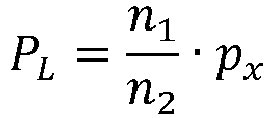
- n 2 q, which means the lens width is a multiple of the fraction 1/q times the pixel width in the row direction, where q is the number of different color sub-pixels.
- RGBW Red, Green, Blue, White
- RGBY Red, Green, Blue, Yellow
- n 4k+1 where k is a positive integer. This means the lens position with respect to the pixels repeats only every 4 lenses, providing a number of fractional views dependent on the number of different color sub-pixels.
- each pixel can comprise four columns of sub-pixels and two rows of sub-pixels with different colors in each column, wherein the combined width of two columns is equal to the combined width of the other two columns.
- the pixel can comprise an RGBW pixel, and the pixel column widths can all be the same.
- the red and blue sub-pixels can have the same width and the green and yellow sub-pixels have the same width.
- the yellow and green sub-pixels can be narrower than the red and blue sub-pixels.
- the rows of pixels are parallel to a top edge of the display and the columns of pixels are parallel to a side edge of the display.
- a modifed example considers the case where the rows and columns of pixels may be slanted with respect to the horizontal and vertical.
- the invention provides a lenticular autostereoscopic display device with a particular design of the lenticular array (lens pitch and slant angle) to optimize the quality of the views provided to the user, when a pixel layout is used, with color pixels having at least four sub-pixels of at least three mutually different colors.
- the slant angle and lens pitch are related to the pixel pitch (in the row and column directions) as well as to the number of different color sub-pixels.
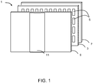
- the known multi-view autostereoscopic display device 1 in Figs. 1 , 2 and 3 comprises a display panel 3, which in this case is an active matrix liquid crystal display (LCD), which acts as an image forming means.
- LCD active matrix liquid crystal display
- the display panel 3 has an array of pixels arranged in orthogonal rows and columns. Each of the pixels is divided in three sub-pixels 5, one green (G), one blue (B) and one red (R) such that columns of R, G and B sub-color pixels exist across the display panel 3.
- RGB layout is entirely conventional and is the same as that indicated with RGB_3 of Fig. 5 . It is also observed in Fig. 3 in the display panel 3.
- the structure of the LCD panel 3 is entirely conventional. Without detail, the panel 3 comprises a pair of spaced transparent glass substrates, between which an aligned twisted nematic or other liquid crystal material is provided.
- the substrates carry patterns of transparent indium tin oxide (ITO) electrodes on their facing surfaces.
- ITO transparent indium tin oxide
- Polarizing layers are also provided on the outer surfaces of the substrates.
- Each sub-pixel comprises opposing electrodes on the substrates, with the intervening liquid crystal material there between.
- the shape and layout of the sub-pixels 5 are determined by the shape and layout of the electrodes and a black matrix arrangement provided on the front of the panel 3.
- the sub-pixels 5 are regularly spaced from one another by gaps.
- Each sub-pixel 5 is associated with a switching element, such as a thin film transistor (TFT) or thin film diode (TFD).
- TFT thin film transistor
- TFD thin film diode
- the pixels are operated to produce the display by providing addressing signals to the switching elements, and suitable addressing schemes will be known to those skilled in the art.
- the display panel 3 is illuminated by a light source 7 comprising, in this case, a planar backlight 7 extending over the area of the display pixel array. Light from the light source 7 is directed through the display panel 3, with the individual sub-pixels 5 being driven to modulate the light and produce the display.
- a light source 7 comprising, in this case, a planar backlight 7 extending over the area of the display pixel array.
- Light from the light source 7 is directed through the display panel 3, with the individual sub-pixels 5 being driven to modulate the light and produce the display.
- the display device 1 also comprises a lenticular lens sheet/array 9, arranged over the display side of the display panel 3, which performs a view forming function.
- the lenticular lens sheet/array 9 comprises a row of lenticular lenses 11 extending parallel to one another, of which only one is shown with exaggerated dimensions.
- the lenticular lenses each have an imaginary long axis 12 along which there is no lens surface curvature. These long axes of the different lenticular lenses are also parallel.
- the lenticular lenses 11 act as view forming elements to perform the view forming function.
- the lenticular lenses 11 are in the form of convex cylindrical elements, and they act as a light output directing means to provide different images, or views, from the display panel 3 to the eyes of a user positioned in front of the display device 1.
- the autostereoscopic display device 1 shown in Fig. 1 is capable of providing several different perspective views in different directions.
- each lenticular lens 11 overlies a small group of sub-pixels 5 in each row.
- the lenticular element 11 projects each display pixel 5 of a group in a different direction, so as to form the several different views.
- the user's head moves from left to right, his/her eyes will receive different ones of the several views, in turn.
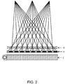
- Fig. 2 shows the principle of operation of a lenticular type imaging arrangement as described above and shows the backlight 7, display panel 3 and the lenticular lens sheet 9.
- the arrangement of Fig. 2 provides three views I, II and III each projected in different directions within a field of view of the display device 1.
- Each sub-pixel of the display panel 3 is driven with information for one specific view.
- the lenticular lenses In systems using a lenticular lens array over a group of pixels to direct them into different views, native display panel pixel resolution is traded for depth; the more views, the higher the loss in resolution per view as every view requires different sub-pixels.
- this resolution loss per view will be exclusively in the horizontal direction, i.e. along the (sub)-color pixel row direction.
- the lenticular lenses are slanted at an acute angle relative to the columns of (sub)- pixels.
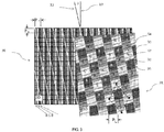
- Fig. 3 shows the native sub-pixel layout 30 of the 2D display panel (reference 3 in Fig. 1 ) having columns of R, G and B that alternate in the row direction, as well as, on the same scale, the sub-pixel layout 31 in a particular view obtained after imaging or projection by the lenticular lenses in front of the display panel.
- the sub-image in the view 31 shown has repeating patterns of R, G or B sub-pixels
- the colors of a few sub-pixels (R, G and B) are indicated so that all colors in the pattern can be understood.
- each color pattern (The pattern of Red, Green or Blue) is output as a diamond shaped grid of sub-pixels which are interleaved with each other.
- the diamond for the green pattern is indicated with the solid and dashed lines.
- each single color sub-pixel of a (3D) view is made up of a whole single color sub-pixel part 32 (G), 34 (R) or 35 (B) and half of a sub-pixel part 33 (e.g. between 32 G and 34 R, or between 32 G and 35 B).
- every sub-pixel of a view has a certain amount of cross talk of neighboring views mixed in.
- the sub-pixels and the grid they define are regular to the extent that sub-pixel dimensions are almost square and no dominating colored slanted columns of such sub-pixels are formed, i.e. all sub-pixels are evenly distributed over the area.
- multi-colored pixel layouts As stated hereinbefore, display manufacturers started looking into alternative pixel layouts that use more than 3 sub-pixels of which having at least three have different (primary) colors. Pixel layouts using more than 3 colors will be termed "multi-colored" pixel layouts. Several such multi-colored layouts have reached the market and are expected to become mainstream for regular two dimensional display devices. These pixel layouts all may have advantages in terms of perceived image resolution and/or brightness for 2D images.
- the invention now is concerned with the choice of the slant angle of the lenticular as well as its pitch such that a number of requirements are fulfilled as much as possible:
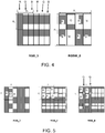
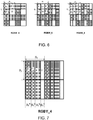
- Figures 4 to 7 show several ones of such alternative pixel layouts.
- the sub-pixel colors for at least one pixel are identified with letter labels ("R", "G", "B” etc.).
- the pixels are in repeating patterns. Where whole columns of pixels have the same color, these are identified from above the columns. The colors of only enough pixels have been shown for the repeating pattern to be identified.
- p x denotes the pitch of a pixel in the row direction
- p y denotes the pitch of a pixel in the column direction.
- Fig. 4 shows a conventional pixel layout of a 2x2 matrix of RGB pixels like the one described in relation to Figs 1 to 3 .
- Each color pixel has three sub-pixels, hence the subscript "3" in RGB_3 (the same notation is used for all pixel layouts).
- Fig. 4 shows a multi-colored pixel layout RGBW_8 pixel arrangement having 4 colors and 8 sub-pixels per pixel.
- RGB Red, Green, Blue
- W white sub-pixels are provided. Comparing the layouts of RGB_3 and RGBW_8 (occupying the same surface area), the perceived resolution of both layouts is similar whereas the RGBW_8 layout results in a higher brightness (at least for LC panels): note that green and white are most important for generating a bright image, since the human eye is more sensitive to green and white light than it is to red and blue light.
- Fig. 5 shows several alternative RGB pixel layouts with more than three sub-color pixels per color pixel.
- the left image of Fig 5 again is the conventional RGB_3 pixel layout.
- the RGB_6 layout in the middle essentially spatially inverts two pairs of RGB pixels.
- the RGB_8 layout on the right has made it to the market for 2D displays by Samsung.
- the green sub-pixels are half as wide as the R and B sub-pixels.
- the green sub-pixels are in columns, whereas the R and B sub-pixels alternate along the column direction.
- Fig. 6 shows three RGBW pixel layouts
- this layout results in a larger color gamut.
- the present invention is thus directed to the problem of designing a lenticular for display panels that make optimum use of such multi-colored pixel layouts, and in a way that preserves the benefits of having more than 3 colors in the 3D display panel.
- the invention has been conceived based on an analysis of ray tracing simulations, to calculate and analyze the pixel layout of a view given the pixel layout of the 2D display panel and given the slant angle ⁇ and pitch P L of the lenticular lenses.
- Fig. 8 shows a first embodiment according to the invention, in respect of the RGBW_8 pixel layout shown in Fig. 6 .
- the results shown are for two different 3D views (these are observed at different viewing angles).
- the 2D panel pixel column direction 13 and long lenticular axis direction 12 and the slant angle theta that they define are indicated in the Fig. 8 .
- the left example viewing angle has a repeating pattern of W,B,G,R sub-pixels in the slanted columns of the lenticulars.
- the adjacent columns are staggered, so that diamond shaped grids of sub-pixels are again defined (with respect to the lenticular axis).
- the axes of a diamond of white sub-pixels are shown in the Fig 8 .
- each 'column' of 3D view sub-pixels (in the direction of the long lenticular axis 12) has a repeating pattern (from top to bottom) which involves eight sub-pixels, in the sequence narrow green portion, wide white portion, narrow red portion, wide blue portion, narrow white portion, wide green portion, wide blue portion, wide red portion.
- each column has wide and narrow portions of the four colors in a sequence.
- Each portion (for example all the wide blue portions) is in the same diamond grid, so that the three objectives above are still met.
- Fig. 9 shows a second embodiment according to the invention, in respect of the same RGBW_3 pixel layout as in Fig. 8 , but with taller pixels.
- the left example viewing angle again has a repeating pattern of W,B,G,R sub-pixels in the slanted columns of the lenticulars.
- the adjacent columns are staggered, so that diamond shaped grids of sub-pixels are again defined (with respect to the lenticular axis).
- the axes of a diamond of white sub-pixels are shown in the Fig 9 .
- Each 'column' (in the direction of the long lenticular axis 12) has a repeating pattern (from top to bottom) which involves eight sub-pixels, in the sequence green, blue, red, green, white, red, blue, white.
- Each set of corresponding portions are again in the same diamond grid, so that the three objectives above are still met.
- Fig. 10 shows a third embodiment of the invention, based on the RGBY_4 pixel layout of Fig. 7 .
- the view has a repeating pattern of B, Y, R, G sub-pixels in the slanted columns of the lenticulars, again staggered so that diamond shaped grids of sub-pixels are defined (with respect to the lenticular axis).
- the display panel pixels do not necessarily have to be arranged on a rectangular grid.
- the unit cell of such a grid can also be trapezoid-shaped. Some examples are shown in Fig. 11 .
- the sub-pixels have the same areas. However, this is not necessarily the case.
- Fig. 12 shows another pixel layout.
- the image to the left is the smallest unit cell of four sub-pixels and shows the colors.
- the pixel layout comprises a repeating pattern of these basic units.
- the pixel contains 4 sub-pixels, not all of them emitting a different primary color.
- the open circles represent the centre of gravity of each of the sub-pixels. In this example, these centers of gravity lie on a rectangular grid.
- the stars in Fig. 12 denote the centre of gravity of a pixel as a whole. In this example, the centers of gravity of the pixels also lie on a rectangular grid.
- Fig. 13 shows another pixel layout.
- each of the 4 different sub-pixels emit a different primary color while the centers of gravity of these sub-pixels do not lie on a rectangular grid.
- each of the sub-pixels constituting a pixel has a different size.
- the centers of gravity of the pixels on the other hand lie on a sheared (i.e. skewed) rectangular grid.
- Fig. 14 represents the most general case for the centers of gravity of the pixels; they lie on a rectangular grid that is skewed in both the x-direction and y-direction.
- a and b are integers. Different combinations of values of a and b relate to different pixel centers.
- the invention is applicable generally to pixel layouts with at least two rows of at least two sub-pixels, and at least three different colors.
- the invention can be applied to all types of display panels, including but not limited to cathode ray tubes, plasma panels, light emitting diode (LED) panels or organic light emitting diode (OLED) display panels.
- cathode ray tubes plasma panels
- LED light emitting diode
- OLED organic light emitting diode
- the invention can be applied to autostereoscopic displays or autostereoscopic displays that can be switched between 2D and 3D view.
- the lenticular lenses may in one mode be switchable between at least two modes of operation, the first being a lens mode for providing the autostereoscopic viewing of the display device and the second mode being a pass through mode for the display panel light for providing the 2D viewing of the display device.
- the lenses may be switchable themselves, or the light provided to the lenses may be manipulated such that the lenses act as pass through or lens. Also switchable graded index lenses may be used with the invention in the switchable autostereoscopic context.
- the lenses of the array may have a curved side and opposite flat side. In this case their orientation may be with their curved side to the display panel or the other way around without loss of effect of the invention.
Claims (12)
- Dispositif d'affichage autostéréoscopique comprenant :- un panneau d'affichage (3) ayant un réseau de pixels, dans lequel les pixels (5) sont agencés en rangées et colonnes et dans lequel chacun des pixels comprend au moins quatre sous-pixels incluant des sous-pixels d'au moins trois couleurs différentes ;- un réseau lenticulaire (9) agencé sur le panneau d'affichage pour projeter une pluralité de vues dans des directions différentes vers un utilisateur, et comprenant des lentilles lenticulaires (11) pour projeter des sorties de groupes de sous-pixels dans la pluralité de vues projetées vers un utilisateur dans des directions différentes, permettant ainsi une imagerie autostéréoscopique, dans lequel les lentilles lenticulaires (11) présentent un axe long qui est incliné selon un angle θ vers la direction générale de pixels en colonne, et présentent un pas PL,dans lequel chaque pixel présente une largeur dans la direction générale de rangée de px et une hauteur dans la direction générale de colonne de py,
et dans lequel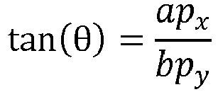
caractérisé en ce que n1/n2 n'est pas un entier, et
- Dispositif selon la revendication 1, dans lequel n2=q.
- Dispositif selon la revendication 2, dans lequel q=4 de sorte que


- Dispositif selon la revendication 3, dans lequel n=4k+1 où k est un entier positif
- Dispositif selon la revendication 4, dans lequel :

- Dispositif selon la revendication 4, dans lequel :

- Dispositif selon l'une quelconque des revendications 3 à 6, dans lequel chaque pixel comprend quatre colonnes de sous-pixels et deux rangées de sous-pixels avec des couleurs différentes dans chaque colonne, dans lequel la largeur combinée de deux colonnes est égale à la largeur combinée des deux autres colonnes.
- Dispositif selon la revendication 7, dans lequel le pixel comprend un pixel RVBW, et les largeurs de colonnes de pixels sont toutes les mêmes.
- Dispositif selon la revendication 3, dans lequel chaque pixel comprend un pixel RVBW ayant quatre colonnes de sous-pixels, et px/py=1 et m=3 et n=4k+2 où k est un entier positif.
- Dispositif selon la revendication 9, dans lequel k=2.
- Dispositif selon la revendication 10, dans lequel les sous-pixels rouges et bleus ont la même largeur et les sous-pixels verts et jaunes ont la même largeur.
- Dispositif selon la revendication 11, dans lequel les sous-pixels jaunes et verts sont plus étroits que les sous-pixels rouges et bleus.
Priority Applications (1)
| Application Number | Priority Date | Filing Date | Title |
|---|---|---|---|
| EP12705451.8A EP2676447B1 (fr) | 2011-02-18 | 2012-02-13 | Dispositif d'affichage autostéréoscopique |
Applications Claiming Priority (3)
| Application Number | Priority Date | Filing Date | Title |
|---|---|---|---|
| EP11154984A EP2490451A1 (fr) | 2011-02-18 | 2011-02-18 | Dispositif d'affichage autostéréoscopique |
| PCT/IB2012/050633 WO2012110934A1 (fr) | 2011-02-18 | 2012-02-13 | Dispositif d'affichage autostéréoscopique |
| EP12705451.8A EP2676447B1 (fr) | 2011-02-18 | 2012-02-13 | Dispositif d'affichage autostéréoscopique |
Publications (2)
| Publication Number | Publication Date |
|---|---|
| EP2676447A1 EP2676447A1 (fr) | 2013-12-25 |
| EP2676447B1 true EP2676447B1 (fr) | 2017-04-12 |
Family
ID=44123493
Family Applications (2)
| Application Number | Title | Priority Date | Filing Date |
|---|---|---|---|
| EP11154984A Withdrawn EP2490451A1 (fr) | 2011-02-18 | 2011-02-18 | Dispositif d'affichage autostéréoscopique |
| EP12705451.8A Active EP2676447B1 (fr) | 2011-02-18 | 2012-02-13 | Dispositif d'affichage autostéréoscopique |
Family Applications Before (1)
| Application Number | Title | Priority Date | Filing Date |
|---|---|---|---|
| EP11154984A Withdrawn EP2490451A1 (fr) | 2011-02-18 | 2011-02-18 | Dispositif d'affichage autostéréoscopique |
Country Status (10)
| Country | Link |
|---|---|
| US (1) | US9250446B2 (fr) |
| EP (2) | EP2490451A1 (fr) |
| JP (1) | JP5838228B2 (fr) |
| KR (1) | KR101875012B1 (fr) |
| CN (1) | CN103348687B (fr) |
| BR (1) | BR112013020715A2 (fr) |
| MX (1) | MX2013009387A (fr) |
| RU (1) | RU2013142345A (fr) |
| TW (1) | TWI562588B (fr) |
| WO (1) | WO2012110934A1 (fr) |
Families Citing this family (48)
| Publication number | Priority date | Publication date | Assignee | Title |
|---|---|---|---|---|
| JP5694026B2 (ja) * | 2011-03-25 | 2015-04-01 | 株式会社ジャパンディスプレイ | 表示装置 |
| CN104221372B (zh) * | 2012-01-26 | 2016-12-14 | 弗劳恩霍弗应用技术研究院 | 自动立体显示器及显示3d图像的方法 |
| US20130286005A1 (en) * | 2012-04-27 | 2013-10-31 | Shenzhen China Star Optoelectronics Technology Co. Ltd. | Three-Dimensional Display Device and Drive Method Thereof |
| CN102759820A (zh) * | 2012-07-20 | 2012-10-31 | 京东方科技集团股份有限公司 | 三视显示器 |
| US9196199B2 (en) | 2013-02-12 | 2015-11-24 | Pixtronix, Inc. | Display having staggered display element arrangement |
| CN103424874B (zh) * | 2013-08-19 | 2015-11-25 | 京东方科技集团股份有限公司 | 3d显示驱动方法 |
| CN103945203A (zh) * | 2013-12-19 | 2014-07-23 | 上海天马微电子有限公司 | 一种立体图像显示装置 |
| JP2017510824A (ja) | 2013-12-20 | 2017-04-13 | コーニンクレッカ フィリップス エヌ ヴェKoninklijke Philips N.V. | オートステレオスコピックディスプレイデバイス |
| WO2015121067A1 (fr) * | 2014-02-13 | 2015-08-20 | Koninklijke Philips N.V. | Panneau d'affichage comportant moins de circuits d'attaque de données |
| KR102141520B1 (ko) * | 2014-02-21 | 2020-08-05 | 삼성전자주식회사 | 무안경 다시점 영상 디스플레이 장치 |
| CN104914586B (zh) * | 2014-03-11 | 2020-07-24 | 北京三星通信技术研究有限公司 | 集成成像显示设备 |
| WO2015137651A1 (fr) * | 2014-03-11 | 2015-09-17 | 삼성전자주식회사 | Affichage d'image intégré, son procédé de fabrication, et système l'incluant |
| TWI524125B (zh) * | 2014-04-16 | 2016-03-01 | 友達光電股份有限公司 | 畫素陣列 |
| CN104035202B (zh) * | 2014-05-23 | 2017-11-10 | 深圳市华星光电技术有限公司 | 一种led 3d显示装置 |
| CN105323573B (zh) | 2014-07-16 | 2019-02-05 | 北京三星通信技术研究有限公司 | 三维图像显示装置和方法 |
| KR102221773B1 (ko) | 2014-09-04 | 2021-03-02 | 삼성디스플레이 주식회사 | 입체 영상 표시 장치 |
| KR20160062312A (ko) | 2014-11-24 | 2016-06-02 | 삼성디스플레이 주식회사 | 입체 영상 표시 장치 |
| KR102009921B1 (ko) | 2014-12-22 | 2019-08-12 | 삼성전자주식회사 | 무안경 3d 디스플레이용 프리즘 시트, 및 이를 구비한 디스플레이 장치 |
| US10234690B2 (en) | 2014-12-24 | 2019-03-19 | Koninklijke Philips N.V. | Autostereoscopic display device |
| CN104599604A (zh) * | 2015-02-16 | 2015-05-06 | 京东方科技集团股份有限公司 | 一种显示装置及其驱动方法 |
| CN104658507B (zh) | 2015-03-18 | 2017-03-08 | 京东方科技集团股份有限公司 | 一种显示面板及其驱动方法和显示装置 |
| WO2016164499A1 (fr) * | 2015-04-06 | 2016-10-13 | Shaw Laurence J | Atténuation de l'effet fantôme de parallaxe de réseau lenticulaire monté pour animation à images multiples |
| US9952426B2 (en) * | 2015-05-28 | 2018-04-24 | Seefront Gmbh | Autostereoscopic system |
| CN106291953B (zh) | 2015-06-05 | 2019-01-08 | 北京智谷睿拓技术服务有限公司 | 显示控制方法和装置 |
| CN106297611B (zh) | 2015-06-05 | 2021-08-10 | 北京智谷睿拓技术服务有限公司 | 显示控制方法和装置 |
| CN106297610B (zh) | 2015-06-05 | 2020-03-17 | 北京智谷睿拓技术服务有限公司 | 显示控制方法和装置 |
| CN105047165A (zh) * | 2015-08-28 | 2015-11-11 | 深圳市华星光电技术有限公司 | 基于rgbw的驱动电路以及平面显示器 |
| CN106559661B (zh) * | 2015-09-30 | 2018-10-02 | 汕头超声显示器(二厂)有限公司 | 一种基于3d液晶透镜的立体视觉图像产生方法 |
| RU2720660C2 (ru) * | 2015-11-10 | 2020-05-12 | Конинклейке Филипс Н.В. | Устройство отображения и способ управления устройством отображения |
| KR102465445B1 (ko) * | 2015-12-04 | 2022-11-09 | 엘지디스플레이 주식회사 | 입체 영상 표시 장치 |
| CN105425407B (zh) | 2015-12-31 | 2019-03-19 | 上海天马微电子有限公司 | 一种3d显示器以及电子设备 |
| CN107105220B (zh) * | 2016-02-22 | 2019-06-14 | 大昱光电股份有限公司 | 一种裸眼立体影像装置 |
| CN105629489B (zh) * | 2016-03-15 | 2018-01-02 | 上海天马微电子有限公司 | 3d显示屏及3d显示装置 |
| TWI614534B (zh) | 2016-09-30 | 2018-02-11 | 台達電子工業股份有限公司 | 多視域顯示器 |
| CN108254934B (zh) * | 2016-12-29 | 2020-07-07 | 南京瀚宇彩欣科技有限责任公司 | 显示装置 |
| US10244230B2 (en) | 2017-03-01 | 2019-03-26 | Avalon Holographics Inc. | Directional pixel for multiple view display |
| JP6925932B2 (ja) | 2017-10-23 | 2021-08-25 | 株式会社ジャパンディスプレイ | 表示装置及び表示方法 |
| CN107942525B (zh) * | 2017-12-22 | 2021-02-02 | 张家港康得新光电材料有限公司 | 显示装置 |
| CN110875361A (zh) * | 2018-08-31 | 2020-03-10 | 京东方科技集团股份有限公司 | 显示基板及显示装置 |
| NL2022313B1 (en) * | 2018-12-24 | 2020-07-21 | Zhangjiagang Kangde Xin Optronics Mat Co Ltd | Autostereoscopic display |
| KR102630592B1 (ko) * | 2018-12-24 | 2024-01-29 | 엘지디스플레이 주식회사 | 다중 패널 표시 장치 |
| EP3687168A1 (fr) * | 2019-01-24 | 2020-07-29 | Ultra-D Coöperatief U.A. | Attribution de numéros de vue pour afficher des éléments d'un affichage autostéréoscopique |
| US20220128835A1 (en) * | 2019-02-05 | 2022-04-28 | Barco N.V. | System and method for passive 3d display |
| JP2022540350A (ja) | 2019-06-28 | 2022-09-15 | ピーシーエムエス ホールディングス インコーポレイテッド | 調整可能な液晶(lc)ディフューザに基づいたライトフィールド(lf)ディスプレイのための光学的方法およびシステム |
| KR20210054652A (ko) | 2019-11-05 | 2021-05-14 | 삼성디스플레이 주식회사 | 표시 모듈 및 그것을 포함하는 표시 장치 |
| CN115079435A (zh) * | 2020-08-03 | 2022-09-20 | 京东方科技集团股份有限公司 | 显示组件、显示装置和驱动方法 |
| US11936844B1 (en) | 2020-08-11 | 2024-03-19 | Apple Inc. | Pre-processing in a display pipeline |
| CN114047639A (zh) * | 2021-11-11 | 2022-02-15 | 东南大学 | 一种超多视点超宽视角的三维显示装置 |
Family Cites Families (14)
| Publication number | Priority date | Publication date | Assignee | Title |
|---|---|---|---|---|
| US6064424A (en) | 1996-02-23 | 2000-05-16 | U.S. Philips Corporation | Autostereoscopic display apparatus |
| GB9603890D0 (en) * | 1996-02-23 | 1996-04-24 | Philips Electronics Nv | Autostereoscopic display apparatus |
| JP4400172B2 (ja) * | 2003-02-28 | 2010-01-20 | 日本電気株式会社 | 画像表示装置、携帯端末装置、表示パネル及び画像表示方法 |
| GB2403863A (en) * | 2003-07-10 | 2005-01-12 | Ocuity Ltd | Colour pixel configuration for an autostereoscopic display |
| JP3701661B2 (ja) * | 2003-12-05 | 2005-10-05 | シャープ株式会社 | 表示パネルおよび表示装置 |
| FR2876805B1 (fr) | 2004-10-18 | 2007-01-05 | Artistic Images Sarl | Dispositif et procede de visualisation autostereoscopique a base de lenticulaire, et procede de synthese d'images autostereoscopiques associe |
| ATE488098T1 (de) * | 2005-09-16 | 2010-11-15 | Koninkl Philips Electronics Nv | Autostereoskopische anzeigevorrichtung und filter dafür |
| KR101364076B1 (ko) * | 2005-11-09 | 2014-02-26 | 코닌클리케 필립스 엔.브이. | 디스플레이를 구동하기 위한 픽셀 신호를 처리하는 방법 및장치와 이를 이용한 디스플레이 |
| KR101357163B1 (ko) * | 2007-08-14 | 2014-02-05 | 삼성전자주식회사 | 휘도를 향상한 오토 스테레오스코픽 디스플레이 장치 |
| TW200933195A (en) * | 2008-01-28 | 2009-08-01 | Ind Tech Res Inst | Autostereoscopic display |
| US20100070564A1 (en) * | 2008-09-12 | 2010-03-18 | Karsten Ehms | Method and apparatus for bidirectional multiplexing of information channels |
| WO2010070564A1 (fr) * | 2008-12-18 | 2010-06-24 | Koninklijke Philips Electronics N.V. | Dispositif d'affichage autostéréoscopique |
| JP5521380B2 (ja) * | 2009-04-13 | 2014-06-11 | ソニー株式会社 | 立体表示装置 |
| DE102009034355B3 (de) * | 2009-07-17 | 2011-01-27 | Fraunhofer-Gesellschaft zur Förderung der angewandten Forschung e.V. | Monitor und Verfahren zum Darstellen autostereoskopisch wahrnehmbarer Bilder |
-
2011
- 2011-02-18 EP EP11154984A patent/EP2490451A1/fr not_active Withdrawn
-
2012
- 2012-02-13 US US14/000,225 patent/US9250446B2/en not_active Expired - Fee Related
- 2012-02-13 RU RU2013142345/08A patent/RU2013142345A/ru not_active Application Discontinuation
- 2012-02-13 MX MX2013009387A patent/MX2013009387A/es active IP Right Grant
- 2012-02-13 EP EP12705451.8A patent/EP2676447B1/fr active Active
- 2012-02-13 BR BR112013020715A patent/BR112013020715A2/pt not_active IP Right Cessation
- 2012-02-13 KR KR1020137024564A patent/KR101875012B1/ko active IP Right Grant
- 2012-02-13 WO PCT/IB2012/050633 patent/WO2012110934A1/fr active Application Filing
- 2012-02-13 CN CN201280009239.4A patent/CN103348687B/zh not_active Expired - Fee Related
- 2012-02-13 JP JP2013554030A patent/JP5838228B2/ja not_active Expired - Fee Related
- 2012-02-16 TW TW101105128A patent/TWI562588B/zh not_active IP Right Cessation
Non-Patent Citations (1)
| Title |
|---|
| None * |
Also Published As
| Publication number | Publication date |
|---|---|
| BR112013020715A2 (pt) | 2016-10-18 |
| CN103348687B (zh) | 2016-06-29 |
| RU2013142345A (ru) | 2015-03-27 |
| KR20140020927A (ko) | 2014-02-19 |
| CN103348687A (zh) | 2013-10-09 |
| WO2012110934A1 (fr) | 2012-08-23 |
| US20140002897A1 (en) | 2014-01-02 |
| TW201240441A (en) | 2012-10-01 |
| EP2490451A1 (fr) | 2012-08-22 |
| US9250446B2 (en) | 2016-02-02 |
| EP2676447A1 (fr) | 2013-12-25 |
| MX2013009387A (es) | 2013-12-06 |
| KR101875012B1 (ko) | 2018-07-06 |
| JP2014511501A (ja) | 2014-05-15 |
| TWI562588B (en) | 2016-12-11 |
| JP5838228B2 (ja) | 2016-01-06 |
Similar Documents
| Publication | Publication Date | Title |
|---|---|---|
| EP2676447B1 (fr) | Dispositif d'affichage autostéréoscopique | |
| US10212413B2 (en) | Autostereoscopic display device | |
| US10257503B2 (en) | Autostereoscopic display device | |
| EP2380355B1 (fr) | Appareil d'affichage autostereoscopique | |
| US8553030B2 (en) | Stereo display apparatus and lens array thereof | |
| KR20120053459A (ko) | 입체 표시 장치 | |
| KR20160058955A (ko) | 자동 입체 디스플레이 디바이스 | |
| JP2013088685A (ja) | 表示装置 | |
| WO2012176102A1 (fr) | Dispositif d'affichage autostéréoscopique | |
| WO2014173853A1 (fr) | Dispositif d'affichage autostéréoscopique à feuille lenticulaire inclinée par rapport à la colonne de sous-pixels colorés | |
| TW201306560A (zh) | 自動立體顯示裝置 |
Legal Events
| Date | Code | Title | Description |
|---|---|---|---|
| PUAI | Public reference made under article 153(3) epc to a published international application that has entered the european phase |
Free format text: ORIGINAL CODE: 0009012 |
|
| 17P | Request for examination filed |
Effective date: 20130918 |
|
| AK | Designated contracting states |
Kind code of ref document: A1 Designated state(s): AL AT BE BG CH CY CZ DE DK EE ES FI FR GB GR HR HU IE IS IT LI LT LU LV MC MK MT NL NO PL PT RO RS SE SI SK SM TR |
|
| DAX | Request for extension of the european patent (deleted) | ||
| REG | Reference to a national code |
Ref country code: DE Ref legal event code: R079 Ref document number: 602012031019 Country of ref document: DE Free format text: PREVIOUS MAIN CLASS: H04N0013000000 Ipc: H04N0013040000 |
|
| GRAP | Despatch of communication of intention to grant a patent |
Free format text: ORIGINAL CODE: EPIDOSNIGR1 |
|
| RIC1 | Information provided on ipc code assigned before grant |
Ipc: H04N 13/04 20060101AFI20160928BHEP |
|
| INTG | Intention to grant announced |
Effective date: 20161012 |
|
| GRAS | Grant fee paid |
Free format text: ORIGINAL CODE: EPIDOSNIGR3 |
|
| GRAA | (expected) grant |
Free format text: ORIGINAL CODE: 0009210 |
|
| AK | Designated contracting states |
Kind code of ref document: B1 Designated state(s): AL AT BE BG CH CY CZ DE DK EE ES FI FR GB GR HR HU IE IS IT LI LT LU LV MC MK MT NL NO PL PT RO RS SE SI SK SM TR |
|
| REG | Reference to a national code |
Ref country code: GB Ref legal event code: FG4D |
|
| REG | Reference to a national code |
Ref country code: CH Ref legal event code: EP |
|
| REG | Reference to a national code |
Ref country code: IE Ref legal event code: FG4D |
|
| REG | Reference to a national code |
Ref country code: AT Ref legal event code: REF Ref document number: 884891 Country of ref document: AT Kind code of ref document: T Effective date: 20170515 |
|
| REG | Reference to a national code |
Ref country code: DE Ref legal event code: R096 Ref document number: 602012031019 Country of ref document: DE |
|
| REG | Reference to a national code |
Ref country code: NL Ref legal event code: MP Effective date: 20170412 |
|
| REG | Reference to a national code |
Ref country code: LT Ref legal event code: MG4D |
|
| REG | Reference to a national code |
Ref country code: AT Ref legal event code: MK05 Ref document number: 884891 Country of ref document: AT Kind code of ref document: T Effective date: 20170412 |
|
| PG25 | Lapsed in a contracting state [announced via postgrant information from national office to epo] |
Ref country code: NL Free format text: LAPSE BECAUSE OF FAILURE TO SUBMIT A TRANSLATION OF THE DESCRIPTION OR TO PAY THE FEE WITHIN THE PRESCRIBED TIME-LIMIT Effective date: 20170412 |
|
| PG25 | Lapsed in a contracting state [announced via postgrant information from national office to epo] |
Ref country code: LT Free format text: LAPSE BECAUSE OF FAILURE TO SUBMIT A TRANSLATION OF THE DESCRIPTION OR TO PAY THE FEE WITHIN THE PRESCRIBED TIME-LIMIT Effective date: 20170412 Ref country code: AT Free format text: LAPSE BECAUSE OF FAILURE TO SUBMIT A TRANSLATION OF THE DESCRIPTION OR TO PAY THE FEE WITHIN THE PRESCRIBED TIME-LIMIT Effective date: 20170412 Ref country code: GR Free format text: LAPSE BECAUSE OF FAILURE TO SUBMIT A TRANSLATION OF THE DESCRIPTION OR TO PAY THE FEE WITHIN THE PRESCRIBED TIME-LIMIT Effective date: 20170713 Ref country code: ES Free format text: LAPSE BECAUSE OF FAILURE TO SUBMIT A TRANSLATION OF THE DESCRIPTION OR TO PAY THE FEE WITHIN THE PRESCRIBED TIME-LIMIT Effective date: 20170412 Ref country code: HR Free format text: LAPSE BECAUSE OF FAILURE TO SUBMIT A TRANSLATION OF THE DESCRIPTION OR TO PAY THE FEE WITHIN THE PRESCRIBED TIME-LIMIT Effective date: 20170412 Ref country code: FI Free format text: LAPSE BECAUSE OF FAILURE TO SUBMIT A TRANSLATION OF THE DESCRIPTION OR TO PAY THE FEE WITHIN THE PRESCRIBED TIME-LIMIT Effective date: 20170412 Ref country code: NO Free format text: LAPSE BECAUSE OF FAILURE TO SUBMIT A TRANSLATION OF THE DESCRIPTION OR TO PAY THE FEE WITHIN THE PRESCRIBED TIME-LIMIT Effective date: 20170712 |
|
| REG | Reference to a national code |
Ref country code: DE Ref legal event code: R079 Ref document number: 602012031019 Country of ref document: DE Free format text: PREVIOUS MAIN CLASS: H04N0013040000 Ipc: H04N0013300000 |
|
| PG25 | Lapsed in a contracting state [announced via postgrant information from national office to epo] |
Ref country code: LV Free format text: LAPSE BECAUSE OF FAILURE TO SUBMIT A TRANSLATION OF THE DESCRIPTION OR TO PAY THE FEE WITHIN THE PRESCRIBED TIME-LIMIT Effective date: 20170412 Ref country code: RS Free format text: LAPSE BECAUSE OF FAILURE TO SUBMIT A TRANSLATION OF THE DESCRIPTION OR TO PAY THE FEE WITHIN THE PRESCRIBED TIME-LIMIT Effective date: 20170412 Ref country code: SE Free format text: LAPSE BECAUSE OF FAILURE TO SUBMIT A TRANSLATION OF THE DESCRIPTION OR TO PAY THE FEE WITHIN THE PRESCRIBED TIME-LIMIT Effective date: 20170412 Ref country code: PL Free format text: LAPSE BECAUSE OF FAILURE TO SUBMIT A TRANSLATION OF THE DESCRIPTION OR TO PAY THE FEE WITHIN THE PRESCRIBED TIME-LIMIT Effective date: 20170412 Ref country code: BG Free format text: LAPSE BECAUSE OF FAILURE TO SUBMIT A TRANSLATION OF THE DESCRIPTION OR TO PAY THE FEE WITHIN THE PRESCRIBED TIME-LIMIT Effective date: 20170712 Ref country code: IS Free format text: LAPSE BECAUSE OF FAILURE TO SUBMIT A TRANSLATION OF THE DESCRIPTION OR TO PAY THE FEE WITHIN THE PRESCRIBED TIME-LIMIT Effective date: 20170812 |
|
| REG | Reference to a national code |
Ref country code: DE Ref legal event code: R097 Ref document number: 602012031019 Country of ref document: DE |
|
| PG25 | Lapsed in a contracting state [announced via postgrant information from national office to epo] |
Ref country code: CZ Free format text: LAPSE BECAUSE OF FAILURE TO SUBMIT A TRANSLATION OF THE DESCRIPTION OR TO PAY THE FEE WITHIN THE PRESCRIBED TIME-LIMIT Effective date: 20170412 Ref country code: SK Free format text: LAPSE BECAUSE OF FAILURE TO SUBMIT A TRANSLATION OF THE DESCRIPTION OR TO PAY THE FEE WITHIN THE PRESCRIBED TIME-LIMIT Effective date: 20170412 Ref country code: DK Free format text: LAPSE BECAUSE OF FAILURE TO SUBMIT A TRANSLATION OF THE DESCRIPTION OR TO PAY THE FEE WITHIN THE PRESCRIBED TIME-LIMIT Effective date: 20170412 Ref country code: RO Free format text: LAPSE BECAUSE OF FAILURE TO SUBMIT A TRANSLATION OF THE DESCRIPTION OR TO PAY THE FEE WITHIN THE PRESCRIBED TIME-LIMIT Effective date: 20170412 Ref country code: EE Free format text: LAPSE BECAUSE OF FAILURE TO SUBMIT A TRANSLATION OF THE DESCRIPTION OR TO PAY THE FEE WITHIN THE PRESCRIBED TIME-LIMIT Effective date: 20170412 |
|
| PLBE | No opposition filed within time limit |
Free format text: ORIGINAL CODE: 0009261 |
|
| STAA | Information on the status of an ep patent application or granted ep patent |
Free format text: STATUS: NO OPPOSITION FILED WITHIN TIME LIMIT |
|
| REG | Reference to a national code |
Ref country code: FR Ref legal event code: PLFP Year of fee payment: 7 |
|
| PG25 | Lapsed in a contracting state [announced via postgrant information from national office to epo] |
Ref country code: SM Free format text: LAPSE BECAUSE OF FAILURE TO SUBMIT A TRANSLATION OF THE DESCRIPTION OR TO PAY THE FEE WITHIN THE PRESCRIBED TIME-LIMIT Effective date: 20170412 Ref country code: IT Free format text: LAPSE BECAUSE OF FAILURE TO SUBMIT A TRANSLATION OF THE DESCRIPTION OR TO PAY THE FEE WITHIN THE PRESCRIBED TIME-LIMIT Effective date: 20170412 |
|
| 26N | No opposition filed |
Effective date: 20180115 |
|
| PG25 | Lapsed in a contracting state [announced via postgrant information from national office to epo] |
Ref country code: SI Free format text: LAPSE BECAUSE OF FAILURE TO SUBMIT A TRANSLATION OF THE DESCRIPTION OR TO PAY THE FEE WITHIN THE PRESCRIBED TIME-LIMIT Effective date: 20170412 |
|
| REG | Reference to a national code |
Ref country code: CH Ref legal event code: PL |
|
| PG25 | Lapsed in a contracting state [announced via postgrant information from national office to epo] |
Ref country code: MC Free format text: LAPSE BECAUSE OF FAILURE TO SUBMIT A TRANSLATION OF THE DESCRIPTION OR TO PAY THE FEE WITHIN THE PRESCRIBED TIME-LIMIT Effective date: 20170412 |
|
| REG | Reference to a national code |
Ref country code: IE Ref legal event code: MM4A |
|
| REG | Reference to a national code |
Ref country code: BE Ref legal event code: MM Effective date: 20180228 |
|
| PG25 | Lapsed in a contracting state [announced via postgrant information from national office to epo] |
Ref country code: LI Free format text: LAPSE BECAUSE OF NON-PAYMENT OF DUE FEES Effective date: 20180228 Ref country code: CH Free format text: LAPSE BECAUSE OF NON-PAYMENT OF DUE FEES Effective date: 20180228 Ref country code: LU Free format text: LAPSE BECAUSE OF NON-PAYMENT OF DUE FEES Effective date: 20180213 |
|
| PG25 | Lapsed in a contracting state [announced via postgrant information from national office to epo] |
Ref country code: IE Free format text: LAPSE BECAUSE OF NON-PAYMENT OF DUE FEES Effective date: 20180213 |
|
| PG25 | Lapsed in a contracting state [announced via postgrant information from national office to epo] |
Ref country code: BE Free format text: LAPSE BECAUSE OF NON-PAYMENT OF DUE FEES Effective date: 20180228 |
|
| PG25 | Lapsed in a contracting state [announced via postgrant information from national office to epo] |
Ref country code: MT Free format text: LAPSE BECAUSE OF NON-PAYMENT OF DUE FEES Effective date: 20180213 |
|
| PGFP | Annual fee paid to national office [announced via postgrant information from national office to epo] |
Ref country code: DE Payment date: 20200228 Year of fee payment: 9 Ref country code: GB Payment date: 20200226 Year of fee payment: 9 |
|
| PG25 | Lapsed in a contracting state [announced via postgrant information from national office to epo] |
Ref country code: HU Free format text: LAPSE BECAUSE OF FAILURE TO SUBMIT A TRANSLATION OF THE DESCRIPTION OR TO PAY THE FEE WITHIN THE PRESCRIBED TIME-LIMIT; INVALID AB INITIO Effective date: 20120213 Ref country code: PT Free format text: LAPSE BECAUSE OF FAILURE TO SUBMIT A TRANSLATION OF THE DESCRIPTION OR TO PAY THE FEE WITHIN THE PRESCRIBED TIME-LIMIT Effective date: 20170412 |
|
| PG25 | Lapsed in a contracting state [announced via postgrant information from national office to epo] |
Ref country code: CY Free format text: LAPSE BECAUSE OF FAILURE TO SUBMIT A TRANSLATION OF THE DESCRIPTION OR TO PAY THE FEE WITHIN THE PRESCRIBED TIME-LIMIT Effective date: 20170412 Ref country code: MK Free format text: LAPSE BECAUSE OF NON-PAYMENT OF DUE FEES Effective date: 20170412 |
|
| PGFP | Annual fee paid to national office [announced via postgrant information from national office to epo] |
Ref country code: TR Payment date: 20200211 Year of fee payment: 9 Ref country code: FR Payment date: 20200225 Year of fee payment: 9 |
|
| PG25 | Lapsed in a contracting state [announced via postgrant information from national office to epo] |
Ref country code: AL Free format text: LAPSE BECAUSE OF FAILURE TO SUBMIT A TRANSLATION OF THE DESCRIPTION OR TO PAY THE FEE WITHIN THE PRESCRIBED TIME-LIMIT Effective date: 20170412 |
|
| REG | Reference to a national code |
Ref country code: DE Ref legal event code: R119 Ref document number: 602012031019 Country of ref document: DE |
|
| GBPC | Gb: european patent ceased through non-payment of renewal fee |
Effective date: 20210213 |
|
| PG25 | Lapsed in a contracting state [announced via postgrant information from national office to epo] |
Ref country code: DE Free format text: LAPSE BECAUSE OF NON-PAYMENT OF DUE FEES Effective date: 20210901 Ref country code: GB Free format text: LAPSE BECAUSE OF NON-PAYMENT OF DUE FEES Effective date: 20210213 Ref country code: FR Free format text: LAPSE BECAUSE OF NON-PAYMENT OF DUE FEES Effective date: 20210228 |