EP2676143B1 - Charakterisierung von hämostase- und sauerstofftransportparametern - Google Patents
Charakterisierung von hämostase- und sauerstofftransportparametern Download PDFInfo
- Publication number
- EP2676143B1 EP2676143B1 EP12865373.0A EP12865373A EP2676143B1 EP 2676143 B1 EP2676143 B1 EP 2676143B1 EP 12865373 A EP12865373 A EP 12865373A EP 2676143 B1 EP2676143 B1 EP 2676143B1
- Authority
- EP
- European Patent Office
- Prior art keywords
- parameter
- blood
- sample
- blood sample
- displacement
- Prior art date
- Legal status (The legal status is an assumption and is not a legal conclusion. Google has not performed a legal analysis and makes no representation as to the accuracy of the status listed.)
- Active
Links
- 239000008280 blood Substances 0.000 title claims description 164
- 210000004369 blood Anatomy 0.000 title claims description 163
- 230000023597 hemostasis Effects 0.000 title claims description 55
- QVGXLLKOCUKJST-UHFFFAOYSA-N atomic oxygen Chemical compound [O] QVGXLLKOCUKJST-UHFFFAOYSA-N 0.000 title claims description 36
- 239000001301 oxygen Substances 0.000 title claims description 36
- 229910052760 oxygen Inorganic materials 0.000 title claims description 36
- 238000012512 characterization method Methods 0.000 title description 6
- 238000006073 displacement reaction Methods 0.000 claims description 86
- 238000005259 measurement Methods 0.000 claims description 81
- 238000002604 ultrasonography Methods 0.000 claims description 28
- 210000002381 plasma Anatomy 0.000 claims description 21
- 108010049003 Fibrinogen Proteins 0.000 claims description 15
- 102000008946 Fibrinogen Human genes 0.000 claims description 15
- 229940012952 fibrinogen Drugs 0.000 claims description 15
- 102000015081 Blood Coagulation Factors Human genes 0.000 claims description 10
- 108010039209 Blood Coagulation Factors Proteins 0.000 claims description 10
- 239000003114 blood coagulation factor Substances 0.000 claims description 10
- 230000020764 fibrinolysis Effects 0.000 claims description 7
- 230000001567 anti-fibrinolytic effect Effects 0.000 claims description 3
- 239000000504 antifibrinolytic agent Substances 0.000 claims description 3
- 229940082620 antifibrinolytics Drugs 0.000 claims description 3
- 239000004023 fresh frozen plasma Substances 0.000 claims description 3
- 239000003634 thrombocyte concentrate Substances 0.000 claims description 3
- 238000011002 quantification Methods 0.000 claims 1
- 239000000523 sample Substances 0.000 description 163
- 238000005534 hematocrit Methods 0.000 description 83
- 238000000034 method Methods 0.000 description 65
- 230000006870 function Effects 0.000 description 44
- 210000003743 erythrocyte Anatomy 0.000 description 28
- 230000008569 process Effects 0.000 description 28
- 230000005855 radiation Effects 0.000 description 28
- 230000032258 transport Effects 0.000 description 26
- BWGVNKXGVNDBDI-UHFFFAOYSA-N Fibrin monomer Chemical compound CNC(=O)CNC(=O)CN BWGVNKXGVNDBDI-UHFFFAOYSA-N 0.000 description 25
- 102000009123 Fibrin Human genes 0.000 description 23
- 108010073385 Fibrin Proteins 0.000 description 23
- 229950003499 fibrin Drugs 0.000 description 23
- 238000012360 testing method Methods 0.000 description 23
- 210000001519 tissue Anatomy 0.000 description 23
- 239000000306 component Substances 0.000 description 20
- 230000035602 clotting Effects 0.000 description 19
- 102000001554 Hemoglobins Human genes 0.000 description 17
- 108010054147 Hemoglobins Proteins 0.000 description 17
- 239000000463 material Substances 0.000 description 17
- WXPZDDCNKXMOMC-AVGNSLFASA-N (2s)-1-[(2s)-2-[[(2s)-1-(2-aminoacetyl)pyrrolidine-2-carbonyl]amino]-5-(diaminomethylideneamino)pentanoyl]pyrrolidine-2-carboxylic acid Chemical compound NCC(=O)N1CCC[C@H]1C(=O)N[C@@H](CCCNC(N)=N)C(=O)N1[C@H](C(O)=O)CCC1 WXPZDDCNKXMOMC-AVGNSLFASA-N 0.000 description 14
- 206010053567 Coagulopathies Diseases 0.000 description 14
- 108090000435 Urokinase-type plasminogen activator Proteins 0.000 description 14
- 230000015271 coagulation Effects 0.000 description 14
- 238000005345 coagulation Methods 0.000 description 14
- 108010017446 glycyl-prolyl-arginyl-proline Proteins 0.000 description 14
- 102000003990 Urokinase-type plasminogen activator Human genes 0.000 description 13
- 238000002474 experimental method Methods 0.000 description 13
- 230000002439 hemostatic effect Effects 0.000 description 13
- 230000033001 locomotion Effects 0.000 description 13
- 238000012545 processing Methods 0.000 description 13
- 230000005540 biological transmission Effects 0.000 description 12
- 230000003247 decreasing effect Effects 0.000 description 12
- 210000004872 soft tissue Anatomy 0.000 description 12
- 238000011282 treatment Methods 0.000 description 12
- 208000007536 Thrombosis Diseases 0.000 description 11
- 230000001934 delay Effects 0.000 description 11
- 238000002592 echocardiography Methods 0.000 description 11
- 230000004044 response Effects 0.000 description 11
- 238000006116 polymerization reaction Methods 0.000 description 10
- 229960000446 abciximab Drugs 0.000 description 9
- 238000004422 calculation algorithm Methods 0.000 description 9
- 239000003153 chemical reaction reagent Substances 0.000 description 9
- 238000001514 detection method Methods 0.000 description 9
- 230000000694 effects Effects 0.000 description 9
- 230000035945 sensitivity Effects 0.000 description 9
- 230000003044 adaptive effect Effects 0.000 description 8
- 238000004090 dissolution Methods 0.000 description 8
- 229960005356 urokinase Drugs 0.000 description 8
- 230000008878 coupling Effects 0.000 description 7
- 238000010168 coupling process Methods 0.000 description 7
- 238000005859 coupling reaction Methods 0.000 description 7
- 230000003480 fibrinolytic effect Effects 0.000 description 7
- 238000000338 in vitro Methods 0.000 description 7
- 239000005995 Aluminium silicate Substances 0.000 description 6
- 235000012211 aluminium silicate Nutrition 0.000 description 6
- 238000004458 analytical method Methods 0.000 description 6
- 238000004364 calculation method Methods 0.000 description 6
- 210000004027 cell Anatomy 0.000 description 6
- 239000003527 fibrinolytic agent Substances 0.000 description 6
- NLYAJNPCOHFWQQ-UHFFFAOYSA-N kaolin Chemical compound O.O.O=[Al]O[Si](=O)O[Si](=O)O[Al]=O NLYAJNPCOHFWQQ-UHFFFAOYSA-N 0.000 description 6
- 208000010110 spontaneous platelet aggregation Diseases 0.000 description 6
- 238000003860 storage Methods 0.000 description 6
- 238000010521 absorption reaction Methods 0.000 description 5
- 230000004913 activation Effects 0.000 description 5
- 230000008901 benefit Effects 0.000 description 5
- 238000005314 correlation function Methods 0.000 description 5
- 230000009089 cytolysis Effects 0.000 description 5
- 238000010586 diagram Methods 0.000 description 5
- 238000001727 in vivo Methods 0.000 description 5
- 102000004169 proteins and genes Human genes 0.000 description 5
- 108090000623 proteins and genes Proteins 0.000 description 5
- FAPWRFPIFSIZLT-UHFFFAOYSA-M Sodium chloride Chemical compound [Na+].[Cl-] FAPWRFPIFSIZLT-UHFFFAOYSA-M 0.000 description 4
- 230000015572 biosynthetic process Effects 0.000 description 4
- 230000023555 blood coagulation Effects 0.000 description 4
- 230000001413 cellular effect Effects 0.000 description 4
- 230000008859 change Effects 0.000 description 4
- 230000006378 damage Effects 0.000 description 4
- 238000011161 development Methods 0.000 description 4
- 230000007246 mechanism Effects 0.000 description 4
- 239000012528 membrane Substances 0.000 description 4
- 239000000243 solution Substances 0.000 description 4
- 238000012546 transfer Methods 0.000 description 4
- 238000012935 Averaging Methods 0.000 description 3
- 206010051055 Deep vein thrombosis Diseases 0.000 description 3
- 102000003886 Glycoproteins Human genes 0.000 description 3
- 108090000288 Glycoproteins Proteins 0.000 description 3
- 206010059484 Haemodilution Diseases 0.000 description 3
- 239000004793 Polystyrene Substances 0.000 description 3
- 108090000190 Thrombin Proteins 0.000 description 3
- 206010047249 Venous thrombosis Diseases 0.000 description 3
- 230000002776 aggregation Effects 0.000 description 3
- 238000004220 aggregation Methods 0.000 description 3
- 230000001455 anti-clotting effect Effects 0.000 description 3
- 230000006399 behavior Effects 0.000 description 3
- 230000017531 blood circulation Effects 0.000 description 3
- 230000003750 conditioning effect Effects 0.000 description 3
- 230000001419 dependent effect Effects 0.000 description 3
- 229920001971 elastomer Polymers 0.000 description 3
- 238000011156 evaluation Methods 0.000 description 3
- 238000001914 filtration Methods 0.000 description 3
- 239000012530 fluid Substances 0.000 description 3
- 230000010354 integration Effects 0.000 description 3
- 230000006623 intrinsic pathway Effects 0.000 description 3
- 230000004048 modification Effects 0.000 description 3
- 238000012986 modification Methods 0.000 description 3
- 230000003287 optical effect Effects 0.000 description 3
- 230000037361 pathway Effects 0.000 description 3
- 230000000704 physical effect Effects 0.000 description 3
- -1 platelets Substances 0.000 description 3
- 229920002223 polystyrene Polymers 0.000 description 3
- 230000002829 reductive effect Effects 0.000 description 3
- 229940107685 reopro Drugs 0.000 description 3
- 239000001509 sodium citrate Substances 0.000 description 3
- NLJMYIDDQXHKNR-UHFFFAOYSA-K sodium citrate Chemical compound O.O.[Na+].[Na+].[Na+].[O-]C(=O)CC(O)(CC([O-])=O)C([O-])=O NLJMYIDDQXHKNR-UHFFFAOYSA-K 0.000 description 3
- 239000000126 substance Substances 0.000 description 3
- 229960004072 thrombin Drugs 0.000 description 3
- 108010094028 Prothrombin Proteins 0.000 description 2
- 102100027378 Prothrombin Human genes 0.000 description 2
- 108010000499 Thromboplastin Proteins 0.000 description 2
- 102000002262 Thromboplastin Human genes 0.000 description 2
- 208000027418 Wounds and injury Diseases 0.000 description 2
- 238000013459 approach Methods 0.000 description 2
- 238000006243 chemical reaction Methods 0.000 description 2
- 239000000470 constituent Substances 0.000 description 2
- 238000013016 damping Methods 0.000 description 2
- 230000007423 decrease Effects 0.000 description 2
- 239000012470 diluted sample Substances 0.000 description 2
- 238000010790 dilution Methods 0.000 description 2
- 239000012895 dilution Substances 0.000 description 2
- 230000005284 excitation Effects 0.000 description 2
- 230000006624 extrinsic pathway Effects 0.000 description 2
- 230000006872 improvement Effects 0.000 description 2
- 239000003112 inhibitor Substances 0.000 description 2
- 208000014674 injury Diseases 0.000 description 2
- 230000003993 interaction Effects 0.000 description 2
- 230000000670 limiting effect Effects 0.000 description 2
- 239000007788 liquid Substances 0.000 description 2
- 238000013178 mathematical model Methods 0.000 description 2
- 238000012544 monitoring process Methods 0.000 description 2
- 229940021182 non-steroidal anti-inflammatory drug Drugs 0.000 description 2
- 238000012014 optical coherence tomography Methods 0.000 description 2
- 239000004033 plastic Substances 0.000 description 2
- 229920003023 plastic Polymers 0.000 description 2
- 239000000843 powder Substances 0.000 description 2
- 238000003825 pressing Methods 0.000 description 2
- 108090000765 processed proteins & peptides Proteins 0.000 description 2
- 229940039716 prothrombin Drugs 0.000 description 2
- 230000002441 reversible effect Effects 0.000 description 2
- 239000011780 sodium chloride Substances 0.000 description 2
- 239000007787 solid Substances 0.000 description 2
- 230000005236 sound signal Effects 0.000 description 2
- 238000003756 stirring Methods 0.000 description 2
- 238000012384 transportation and delivery Methods 0.000 description 2
- 210000003462 vein Anatomy 0.000 description 2
- XLYOFNOQVPJJNP-UHFFFAOYSA-N water Substances O XLYOFNOQVPJJNP-UHFFFAOYSA-N 0.000 description 2
- 239000005552 B01AC04 - Clopidogrel Substances 0.000 description 1
- 102000004506 Blood Proteins Human genes 0.000 description 1
- 108010017384 Blood Proteins Proteins 0.000 description 1
- UXVMQQNJUSDDNG-UHFFFAOYSA-L Calcium chloride Chemical compound [Cl-].[Cl-].[Ca+2] UXVMQQNJUSDDNG-UHFFFAOYSA-L 0.000 description 1
- 108050001049 Extracellular proteins Proteins 0.000 description 1
- 208000032843 Hemorrhage Diseases 0.000 description 1
- 241001529936 Murinae Species 0.000 description 1
- 239000002033 PVDF binder Substances 0.000 description 1
- 102000015795 Platelet Membrane Glycoproteins Human genes 0.000 description 1
- 108010010336 Platelet Membrane Glycoproteins Proteins 0.000 description 1
- 239000004952 Polyamide Substances 0.000 description 1
- 239000004698 Polyethylene Substances 0.000 description 1
- 239000004743 Polypropylene Substances 0.000 description 1
- 208000010378 Pulmonary Embolism Diseases 0.000 description 1
- 206010037394 Pulmonary haemorrhage Diseases 0.000 description 1
- 102000012479 Serine Proteases Human genes 0.000 description 1
- 108010022999 Serine Proteases Proteins 0.000 description 1
- VYPSYNLAJGMNEJ-UHFFFAOYSA-N Silicium dioxide Chemical compound O=[Si]=O VYPSYNLAJGMNEJ-UHFFFAOYSA-N 0.000 description 1
- 208000006011 Stroke Diseases 0.000 description 1
- 102100031358 Urokinase-type plasminogen activator Human genes 0.000 description 1
- 230000003213 activating effect Effects 0.000 description 1
- 239000012190 activator Substances 0.000 description 1
- 230000006978 adaptation Effects 0.000 description 1
- 239000000556 agonist Substances 0.000 description 1
- XAGFODPZIPBFFR-UHFFFAOYSA-N aluminium Chemical compound [Al] XAGFODPZIPBFFR-UHFFFAOYSA-N 0.000 description 1
- 229910052782 aluminium Inorganic materials 0.000 description 1
- 239000005557 antagonist Substances 0.000 description 1
- 230000002429 anti-coagulating effect Effects 0.000 description 1
- 210000001367 artery Anatomy 0.000 description 1
- 238000003556 assay Methods 0.000 description 1
- 238000005311 autocorrelation function Methods 0.000 description 1
- 230000000740 bleeding effect Effects 0.000 description 1
- 230000000903 blocking effect Effects 0.000 description 1
- 208000015294 blood coagulation disease Diseases 0.000 description 1
- 239000012503 blood component Substances 0.000 description 1
- 239000001110 calcium chloride Substances 0.000 description 1
- 229910001628 calcium chloride Inorganic materials 0.000 description 1
- 239000003795 chemical substances by application Substances 0.000 description 1
- GKTWGGQPFAXNFI-HNNXBMFYSA-N clopidogrel Chemical compound C1([C@H](N2CC=3C=CSC=3CC2)C(=O)OC)=CC=CC=C1Cl GKTWGGQPFAXNFI-HNNXBMFYSA-N 0.000 description 1
- 239000000701 coagulant Substances 0.000 description 1
- 230000009852 coagulant defect Effects 0.000 description 1
- 230000001427 coherent effect Effects 0.000 description 1
- 238000004590 computer program Methods 0.000 description 1
- 239000012611 container material Substances 0.000 description 1
- 230000008828 contractile function Effects 0.000 description 1
- 238000007887 coronary angioplasty Methods 0.000 description 1
- 230000001351 cycling effect Effects 0.000 description 1
- 230000000593 degrading effect Effects 0.000 description 1
- 230000003111 delayed effect Effects 0.000 description 1
- 238000000151 deposition Methods 0.000 description 1
- 238000013461 design Methods 0.000 description 1
- 229940079593 drug Drugs 0.000 description 1
- 239000003814 drug Substances 0.000 description 1
- 230000009977 dual effect Effects 0.000 description 1
- 230000004064 dysfunction Effects 0.000 description 1
- 239000007789 gas Substances 0.000 description 1
- 230000007274 generation of a signal involved in cell-cell signaling Effects 0.000 description 1
- 239000011521 glass Substances 0.000 description 1
- 239000008187 granular material Substances 0.000 description 1
- 239000004519 grease Substances 0.000 description 1
- 239000005337 ground glass Substances 0.000 description 1
- 238000010438 heat treatment Methods 0.000 description 1
- 208000031169 hemorrhagic disease Diseases 0.000 description 1
- 238000004128 high performance liquid chromatography Methods 0.000 description 1
- 238000003384 imaging method Methods 0.000 description 1
- 230000005764 inhibitory process Effects 0.000 description 1
- 238000003780 insertion Methods 0.000 description 1
- 230000037431 insertion Effects 0.000 description 1
- 230000002452 interceptive effect Effects 0.000 description 1
- 229920000126 latex Polymers 0.000 description 1
- 239000004816 latex Substances 0.000 description 1
- 210000000265 leukocyte Anatomy 0.000 description 1
- 238000012417 linear regression Methods 0.000 description 1
- 238000012423 maintenance Methods 0.000 description 1
- 238000004519 manufacturing process Methods 0.000 description 1
- 239000011159 matrix material Substances 0.000 description 1
- 238000000691 measurement method Methods 0.000 description 1
- 230000005226 mechanical processes and functions Effects 0.000 description 1
- 230000001404 mediated effect Effects 0.000 description 1
- 239000004005 microsphere Substances 0.000 description 1
- 239000000203 mixture Substances 0.000 description 1
- 230000008450 motivation Effects 0.000 description 1
- 208000010125 myocardial infarction Diseases 0.000 description 1
- 230000007170 pathology Effects 0.000 description 1
- 230000002093 peripheral effect Effects 0.000 description 1
- 230000010363 phase shift Effects 0.000 description 1
- 239000008363 phosphate buffer Substances 0.000 description 1
- 230000004962 physiological condition Effects 0.000 description 1
- 230000035790 physiological processes and functions Effects 0.000 description 1
- 229940012957 plasmin Drugs 0.000 description 1
- 230000033885 plasminogen activation Effects 0.000 description 1
- 229940020573 plavix Drugs 0.000 description 1
- 229920003223 poly(pyromellitimide-1,4-diphenyl ether) Polymers 0.000 description 1
- 229920002647 polyamide Polymers 0.000 description 1
- 229920000573 polyethylene Polymers 0.000 description 1
- 229920001721 polyimide Polymers 0.000 description 1
- 229920000642 polymer Polymers 0.000 description 1
- 229920001155 polypropylene Polymers 0.000 description 1
- 229920001296 polysiloxane Polymers 0.000 description 1
- 229920000915 polyvinyl chloride Polymers 0.000 description 1
- 239000004800 polyvinyl chloride Substances 0.000 description 1
- 229920002981 polyvinylidene fluoride Polymers 0.000 description 1
- 230000003389 potentiating effect Effects 0.000 description 1
- 102000004196 processed proteins & peptides Human genes 0.000 description 1
- 230000001902 propagating effect Effects 0.000 description 1
- 230000002797 proteolythic effect Effects 0.000 description 1
- 238000005086 pumping Methods 0.000 description 1
- 230000009467 reduction Effects 0.000 description 1
- 230000001105 regulatory effect Effects 0.000 description 1
- 238000012552 review Methods 0.000 description 1
- 230000028327 secretion Effects 0.000 description 1
- 230000008054 signal transmission Effects 0.000 description 1
- 239000003998 snake venom Substances 0.000 description 1
- 241000894007 species Species 0.000 description 1
- 230000006641 stabilisation Effects 0.000 description 1
- 238000011105 stabilization Methods 0.000 description 1
- 230000003068 static effect Effects 0.000 description 1
- 238000013517 stratification Methods 0.000 description 1
- 239000013077 target material Substances 0.000 description 1
- 230000002123 temporal effect Effects 0.000 description 1
- 238000002560 therapeutic procedure Methods 0.000 description 1
- 230000001732 thrombotic effect Effects 0.000 description 1
- 238000011269 treatment regimen Methods 0.000 description 1
- 239000013026 undiluted sample Substances 0.000 description 1
Images


Classifications
-
- G—PHYSICS
- G01—MEASURING; TESTING
- G01N—INVESTIGATING OR ANALYSING MATERIALS BY DETERMINING THEIR CHEMICAL OR PHYSICAL PROPERTIES
- G01N33/00—Investigating or analysing materials by specific methods not covered by groups G01N1/00 - G01N31/00
- G01N33/48—Biological material, e.g. blood, urine; Haemocytometers
- G01N33/483—Physical analysis of biological material
- G01N33/487—Physical analysis of biological material of liquid biological material
- G01N33/49—Blood
- G01N33/4905—Determining clotting time of blood
-
- G—PHYSICS
- G01—MEASURING; TESTING
- G01N—INVESTIGATING OR ANALYSING MATERIALS BY DETERMINING THEIR CHEMICAL OR PHYSICAL PROPERTIES
- G01N33/00—Investigating or analysing materials by specific methods not covered by groups G01N1/00 - G01N31/00
- G01N33/48—Biological material, e.g. blood, urine; Haemocytometers
- G01N33/483—Physical analysis of biological material
- G01N33/487—Physical analysis of biological material of liquid biological material
- G01N33/49—Blood
-
- G—PHYSICS
- G01—MEASURING; TESTING
- G01N—INVESTIGATING OR ANALYSING MATERIALS BY DETERMINING THEIR CHEMICAL OR PHYSICAL PROPERTIES
- G01N29/00—Investigating or analysing materials by the use of ultrasonic, sonic or infrasonic waves; Visualisation of the interior of objects by transmitting ultrasonic or sonic waves through the object
- G01N29/02—Analysing fluids
- G01N29/024—Analysing fluids by measuring propagation velocity or propagation time of acoustic waves
-
- G—PHYSICS
- G01—MEASURING; TESTING
- G01N—INVESTIGATING OR ANALYSING MATERIALS BY DETERMINING THEIR CHEMICAL OR PHYSICAL PROPERTIES
- G01N29/00—Investigating or analysing materials by the use of ultrasonic, sonic or infrasonic waves; Visualisation of the interior of objects by transmitting ultrasonic or sonic waves through the object
- G01N29/02—Analysing fluids
- G01N29/028—Analysing fluids by measuring mechanical or acoustic impedance
-
- G—PHYSICS
- G01—MEASURING; TESTING
- G01N—INVESTIGATING OR ANALYSING MATERIALS BY DETERMINING THEIR CHEMICAL OR PHYSICAL PROPERTIES
- G01N29/00—Investigating or analysing materials by the use of ultrasonic, sonic or infrasonic waves; Visualisation of the interior of objects by transmitting ultrasonic or sonic waves through the object
- G01N29/02—Analysing fluids
- G01N29/032—Analysing fluids by measuring attenuation of acoustic waves
-
- G—PHYSICS
- G01—MEASURING; TESTING
- G01N—INVESTIGATING OR ANALYSING MATERIALS BY DETERMINING THEIR CHEMICAL OR PHYSICAL PROPERTIES
- G01N29/00—Investigating or analysing materials by the use of ultrasonic, sonic or infrasonic waves; Visualisation of the interior of objects by transmitting ultrasonic or sonic waves through the object
- G01N29/44—Processing the detected response signal, e.g. electronic circuits specially adapted therefor
-
- G—PHYSICS
- G01—MEASURING; TESTING
- G01N—INVESTIGATING OR ANALYSING MATERIALS BY DETERMINING THEIR CHEMICAL OR PHYSICAL PROPERTIES
- G01N33/00—Investigating or analysing materials by specific methods not covered by groups G01N1/00 - G01N31/00
- G01N33/48—Biological material, e.g. blood, urine; Haemocytometers
- G01N33/483—Physical analysis of biological material
- G01N33/487—Physical analysis of biological material of liquid biological material
- G01N33/49—Blood
- G01N33/492—Determining multiple analytes
-
- G—PHYSICS
- G01—MEASURING; TESTING
- G01N—INVESTIGATING OR ANALYSING MATERIALS BY DETERMINING THEIR CHEMICAL OR PHYSICAL PROPERTIES
- G01N2291/00—Indexing codes associated with group G01N29/00
- G01N2291/01—Indexing codes associated with the measuring variable
- G01N2291/018—Impedance
-
- G—PHYSICS
- G01—MEASURING; TESTING
- G01N—INVESTIGATING OR ANALYSING MATERIALS BY DETERMINING THEIR CHEMICAL OR PHYSICAL PROPERTIES
- G01N2291/00—Indexing codes associated with group G01N29/00
- G01N2291/02—Indexing codes associated with the analysed material
- G01N2291/022—Liquids
-
- G—PHYSICS
- G01—MEASURING; TESTING
- G01N—INVESTIGATING OR ANALYSING MATERIALS BY DETERMINING THEIR CHEMICAL OR PHYSICAL PROPERTIES
- G01N2291/00—Indexing codes associated with group G01N29/00
- G01N2291/02—Indexing codes associated with the analysed material
- G01N2291/024—Mixtures
- G01N2291/02466—Biological material, e.g. blood
-
- G—PHYSICS
- G01—MEASURING; TESTING
- G01N—INVESTIGATING OR ANALYSING MATERIALS BY DETERMINING THEIR CHEMICAL OR PHYSICAL PROPERTIES
- G01N2291/00—Indexing codes associated with group G01N29/00
- G01N2291/02—Indexing codes associated with the analysed material
- G01N2291/028—Material parameters
- G01N2291/02818—Density, viscosity
-
- G—PHYSICS
- G01—MEASURING; TESTING
- G01N—INVESTIGATING OR ANALYSING MATERIALS BY DETERMINING THEIR CHEMICAL OR PHYSICAL PROPERTIES
- G01N2291/00—Indexing codes associated with group G01N29/00
- G01N2291/04—Wave modes and trajectories
- G01N2291/044—Internal reflections (echoes), e.g. on walls or defects
Definitions
- hemostatic process The formation of a blood clot and its successive dissolution, referred to as the hemostatic process, is required to arrest blood loss from an injured vessel.
- This process is the result of a delicate functional balance between plasma coagulation factors, platelets, and fibrinolytic proteins.
- Each of these elements plays an important role in activating/deactivating the others, and the appropriate stimuli are necessary to prevent excessive blood loss without causing inappropriate thrombosis.
- Disruption of this balance plays a significant role in the onset of potentially fatal conditions, including myocardial infarction, stroke, deep vein thrombosis, pulmonary embolism, and hemorrhage.
- the hemostatic process is initiated by the activation and subsequent adhesion of platelets to the site of injury within the vessel wall.
- Activated platelets recruit other platelets and interact with fibrinogen in the blood plasma to form a platelet-plug that serves as the initial response to stop blood loss. Hemostasis then proceeds with a cascade of proteolytic reactions of the plasma coagulation proteins that ultimately form a three-dimensional network of fibrin that strengthens the platelet-plug.
- the fibrin chains are cross-linked and stabilized by the plasma factor Xllla (FXIIIa). Platelets also have a central role in regulating the process of fibrin polymerization.
- the final step of hemostasis involves the activation of the plasma protein plasmin, which lyses the blood clot when its useful life is over.
- This cell-based model of hemostasis closely reflects the in vivo physiological process.
- a system for determining hemostasis parameters based on monitoring the movement of the cells in a blood sample is known from WO2009123555 .
- the present invention overcomes the problems of the prior art by providing a system for measuring a parameter of a blood sample.
- the system includes an ultrasonic signal generator, a receiver and a processor.
- the ultrasonic signal generator is configured to generate and direct an ultrasonic signal to interact with the blood sample.
- the receiver is configured to determine at least one characteristic of the ultrasonic signal that interacted with the blood sample.
- the processor is configured to determine, using the characteristic, at least one hemostasis parameter and at least on oxygen transport parameter.
- the oxygen transport parameter is selected from a group consisting of HCT, HGB, MCV, RBC, MCHC, MCH and combinations thereof.
- the processor may be further configured to generate a corrected hemostasis parameter using the oxygen transport parameter.
- the hemostasis parameter may be a TC1, TC2, angle, and estimated stiffness S.
- the hemostasis parameter may be an index for a clinical parameter, such as (1) coagulation factors (intrinsic and/or extrinsic), (2) platelet function, (3) fibrinogen and (4) fibrinolysis.
- the processor may also be configured to communicate the clinical parameter to guide transfusion, such as through a graphical user interface (GUI).
- GUI graphical user interface
- the clinical parameter may be (1) fresh frozen plasma, (2) platelet concentrates, (3) cryoprecipitate, (4) antifibrinolytics, and (5) packed RBCs.
- the processor may also be configured to communicate the HCT or other oxygen transport parameter. It could also compare the HCT to an assumed HCT and communicate a difference therebetween. Or, it could determine when the HCT is within a range affecting the parameter and communicate a warning about the parameter.
- a system for evaluating a blood sample could include a processor configured to determine a hemostasis parameter from the blood sample and to determine at least one oxygen transport parameter from the same blood sample.
- the system may also include an ultrasound generator and a receiver. The receiver is configured to receive reflected sound from the blood sample and to convert the received sound into electrical signals.
- the hemostasis parameter is measured by quantifying the displacement induced within the blood sample by application of at least one pulse of ultrasound of sufficient intensity to induce measurable displacement within the blood sample.
- a method not in accordance with the claimed invention includes measuring at least one hemostasis parameter from the blood sample. Also, the method includes measuring at least one oxygen transport parameter from the same blood sample.
- a system for determining properties of at least one tissue sample includes a measurement system, a processor and an integrated aspect.
- the measurement system is configured to determine date characterizing the tissue sample.
- the processor is configured to receive the data and to determine at least one hemostasis parameter and at least one oxygen transport parameter using the data.
- the integrated aspect is configured to facilitate determination of the at least one hemostasis parameter and at least one oxygen transport parameter.
- the data is generated by an application of force to the tissue sample.
- the integrated aspect is a common sample portion.
- the common sample portion is characterized by the hemostasis parameter and oxygen transport parameter.
- a sample container may be included to contain the common sample portion.
- the common sample portion may be a blood sample, for example.
- the measurement system comprises a receiver, wherein the receiver is configured to determine displacement of the tissue sample.
- the measurement system includes an ultrasonic signal generator. It is configured to generate and direct an ultrasonic signal to the tissue sample to induce the displacement.
- the processor may be configured to determine a stiffness of the tissue sample using the displacement. The stiffness can be used to determine the hemostasis parameter.
- the data may also include a speed of sound through the tissue sample.
- the processor is configured to use the speed of sound to determine the oxygen transport parameter.
- the data may also include attenuation of the ultrasonic signal through the tissue sample and use the attenuation to determine the oxygen transport parameter. The speed of sound and/or attenuation can also be used to calibrate the system.
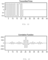
- the ultrasonic signal generator may be configured to adaptively adjust the ultrasonic signal. For example, it may generate a convoluted pulse and the process may be configured to process a corresponding correlation function. For example, the convoluted pulse may be convolved with a Barker code.
- the measurement system may operate in two phases.
- a first phase determines first phase data and a second phase determines second phase data.
- the first phase data is used to determine the hemostasis parameter.
- the second phase data is used tod etermin the oxygen transport parameter.
- the phases may occur in series.
- the measurement system may be configured to determine the data by querying a plurality of channels. And, the system may be configured to operate in a plurality of cycles. Each cycle includes acquisition of the data by the measurement system and processing of the data by the processor.
- the processor may be further configured to adjust the hemostasis parameter using the oxygen transport parameter.
- the integrated aspect may also include a common portion of the data used by the processor to determine the oxygen transport parameter and the hemostasis parameter.
- the oxygen transport parameter may, for example, be one or more of HCT, HGB, MCV, RBC, MCHC and MCH.
- the integrated aspect may also include an ultrasound transducer and receiver of the measurement system.
- the transducer and receiver may be positioned on opposite sides of the tissue sample.
- the processor may be configured to perform a physiological adjustment to the hemostasis parameter.
- the physiological adjustment may be based on the oxygen transport parameter.
- the processor may be configured to perform a physical adjustment to the hemostasis parameter.
- the physical adjustment may be based on one of a speed or attenuation of a sound signal through the tissue sample.
- the system may also include a GUI configured to display both the hemostasis parameter and the oxygen parameter simultaneously.
- the present invention provides systems for performing what the present inventors have termed sonorheometry.
- Sonorheometry provides data about the mechanical properties of soft tissue. Furthermore, repeated measurements using sonorheometry enable characterization of changing properties over time. Sonorheometry is particularly well-suited to characterizing blood coagulation and clot dissolution (i.e., the hemostatic process).
- the present invention provides data about the mechanical properties of a developing and later dissolving clot without disrupting the underlying processes.
- the methods and techniques may be non-invasive or carried out in a laboratory setting after obtaining a sample from a patient, and are based on the application of acoustic radiation force to the tissue to be characterized.
- An increased or decreased propensity to clot can be evaluated by observing the coagulation rate and mechanical characteristics of the developing clot at any time during formation and dissolution. This information may in turn allow clinicians to assess an individual's clotting behavior and to treat coagulation disorders appropriately. This information may also be used to evaluate whether a particular treatment and/or dosage is effective or needs to be changed, as subsequent testing according to the present methods (i.e., after a treatment has been administered) can be carried out to compare the results, thereby indicating the effect of the treatment.
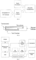
- an assembly 1 is schematically shown that is set up for testing soft tissue according to the present invention.
- An acoustic wave generating device 10 is positioned in alignment with container 30 to allow device 10 to irradiate a soft tissue contained within container 30.
- Device 10 may be mounted or fixed at a predetermined distance for the contents of the container 30 to receive focused acoustical waves from device 10.
- device 10 and container 30 are oriented to align the emission of acoustic waves from device 10 with a sample contained in container 30.
- Container 30 may be entirely acoustically transparent, or contains at least one window 32a that is acoustically transparent and that is aligned with the emission pathway of device 10.
- container 30 may include a plastic cuvette having windows 32a and 32d, as shown in FIG. 1B , cut therethrough and covered with KAPTON ® (polyimide) film or other at least partially acoustically permissive material.
- KAPTON ® polyimide
- acoustic window or windows of the sample container may be placed at some non-perpendicular angle relative to the direction of wave propagation so as to reduce the magnitude of received echoes from the interfaces with the window(s).
- Multiple measurements may be performed at the same time using an array of sample containers 30.
- An array may either include multiple individual containers or a single container with multiple sample compartments. Additionally or alternatively, an array of transducers may be included in device 10, or an array of devices 10 may be used to make multiple measurements. Thus, for example, multiple transducers and/or multiple devices 10 may be provided to analyze multiple samples in parallel, wherein the multiple samples are contained in multiple individual containers or a single container with multiple sample compartments.
- Assembly I may be submerged in a tank of water or other coupling medium to facilitate transmission of the acoustic waves.
- device 10 (or other acoustic emitter and receiver) may be placed in direct contact with the sample.
- device 10 may be adapted to deposit the sample directly in contact therewith, for example placing a drop (or other quantity) of blood on a transducer contained in device 10 or other application feature of device 10.
- the bath may be a constant temperature bath or other means may be provided to maintain a constant sample temperature.
- device 10 may be inserted intravascularly and delivered to the location of a stent to characterize any clotting that may be occurring as well as characterize the progression or stage of a clot that may be present.
- Similar intravascular techniques can be applied for identifying and/or characterizing clot processes with regard to Deep Vein Thrombosis (DVT), as well as for other clotting events throughout the body, as long as the location is accessible by catheter or other delivery instrument, for example.
- DVD Deep Vein Thrombosis
- the device may also be positioned at an intra-cavity location or other location inside of the body.
- Device 10 includes an acoustic wave generating source capable of generating one or more pulses, at least one of which is of sufficient intensity to induce measurable physical displacement in the soft tissue contained in container 30.
- device 10 may include one or more piezoelectric transducers capable of generating ultrasonic waves.
- device 10 may utilize an electric circuit to generate rapid heating and thereby generate acoustic energy.
- acoustic energy including, but not limited to: an ultrasonic generator fabricated using microelectromechanical systems (MEMS); a capacitive micromachined ultrasound transducer; a laser used to heat a target material thereby generating acoustic energy, where the laser may be targeted on a permanent component of the assembly, or on a surface of the sample, for example.
- MEMS microelectromechanical systems
- a transducer may be incorporated into the sample container 30 in lieu of providing it in the device 10, as in a case, for example, where a polymer transducer material such as PVDF may be glued right onto the surface of the sample container 30.
- Device 10 further includes at least one sensor capable of measuring displacement or deformation induced by the acoustic waves as they are applied to the soft tissue sample and reflected by the soft tissue sample back to device 10.
- an ultrasound sensor may be used to track the motion of the sample as induced by at least one ultrasonic wave of sufficient intensity to induce displacement of the tissue.
- tracking of the motion may be accomplished by means other than sensing reflected acoustic waves.
- optical coherence tomography a focused light interferometer or laser Doppler may be used to optically sense the displacement of the tissue induced by the one or more ultrasonic waves.
- Device 10 may include one or more sensors for carrying out any of these optical methods or such sensors may be provided in equipment that is separate from device 10.
- the one or more sensors may be one and the same as the acoustic wave generator, or may be a separate component(s) and may take any of the forms described above with regard to the acoustic wave generating component.
- An ultrasonic transducer may be used to both apply ultrasonic waves to the soft tissue as well as to sense ultrasonic waves reflected back from the tissue.
- An adjoining processor (not shown in FIG. 1A ) may be provided to control the timing of transmission of pulses and of receiving of echoes (reflected pulses) by device 10.
- FIG. 1B shows an example wherein a second device 10' is positioned in alignment with device 10, but on the opposite side of container 30 compared to the location of device 10.
- container 30 may be entirely acoustically transparent, or contain at least two windows 32a and 32d that are acoustically transparent and that are aligned with the emission pathway of device 10 to permit emissions to pass through both windows 32a and 32d to be received by device 10'
- System 1 shown in FIG. 1B in addition to performing the measurements that the system of FIG. 1A performs, can also measure acoustic properties, including speed of sound and attenuation, which provide indirect measures of tissue microstructure and which may be used for calibration purposes.
- A is the cross sectional area of the volume of interest (perpendicular to the axis of propagation)
- l 0 is the ultrasound intensity that would be observed in the absence of attenuation
- ⁇ is the amplitude attenuation coefficient in Nepers per centimeter per MHz
- f is the ultrasonic center frequency in MHz
- z 1 and z 2 are the ranges of the front and back of the volume in units of centimeters.
- the system can also measure the waves that pass from device 10 to device 10' and estimate acoustic properties of the sample being analyzed. Examples of acoustic properties that may be estimated include attenuation, scattering, and speed of sound during sonorheometry procedures.
- the data received by device 10' may be used to make predictions/estimations of the applied radiation force and compare experimentally determined displacements to predicted displacements.
- FIG. 1A shows an example of apparatus for performing analysis in vitro (such as in a laboratory setting, or from a self-operated testing kit, for example) after taking a sample to be analyzed from a patient and depositing it in container 30.
- the present invention may also be practiced non-invasively, such as by applying acoustic waves from a device 10 transdermally through a patient (in vivo) to the targeted tissue to be analyzed, see FIG. 1C .
- a single time frame analysis of one or more physical properties of the tissue may be made, or time series studies may be performed by applying the waves transdermally at different time periods, using the techniques described herein for the in vitro studies.
- the in vivo analyses would not involve administration of thrombin or other coagulant to a patient.
- time studies may be done to test the effectiveness of an anti-clotting treatment regimen for example.
- time studies may be done to test the effectiveness of a pro-clotting regimen given to a patient to increase the ability of the blood to clot, such as in the case of a hemophiliac, for example.
- thrombin is not necessarily required for time studies in vitro, as there are other techniques that may be substituted to initiate coagulation, such as snake venom, kaolin, celite, tissue factor, the use of ground glass to initiate coagulation, etc.
- Non-invasive applications of the current invention include characterizing a stage of development of a blood clot by generating a series of acoustic pulses and transdermally directing the series of pulses into the blood such that at least one of the pulses are of sufficiently high intensity to induce physical displacement of the blood, receiving at least two pulses, including at least one pulse reflected from the blood to establish a baseline and another pulse reflected from the blood to estimate at least one characteristic of the physical displacement induced by the waves.
- the at least two pulses identified above as being used for establishing baseline and estimating a characteristic resulting from the physical displacement of the sample do not necessarily have to be reflected from the blood/sample.
- the at least two pulses could alternatively be those reflected from the surfaces of the flexible sample container or other membranes placed within the sample, as the movement of the sample (e.g., development of the clot) will alter the position of the surfaces or membranes.
- the at least one estimate may be compared to previously generated data to gauge the stage of development of the blood clot being analyzed.
- the previously generated data may be reference data, such as generated across a larger number of patients and then averaged to determine normal characteristics, as well as to find average levels for characterizing different stages of clotting for example.
- one or more algorithms, techniques or statistical processes may be applied to the at least one estimate to correct for attenuation, scatter and/or other variables before making comparisons to the previously generated data and/or database.
- the prior data or previously generated data may be data generated from one or more previous applications of the present invention to the same patient for the same tissue at prior times.
- This approach may be used to develop a history, to show the progression of the development of the clot for example.
- the in vitro apparatus described herein could be used to carry out the same tests outside of the body, such as in a laboratory or a patient's home test kit.
- Still further evaluation of the effectiveness of an anti-clotting treatment may be performed, such as by evaluating the blood prior to application of the treatment by generating a series of acoustic pulses and directing the series of pulses into the blood such that at least one of the pulses is of sufficiently high intensity to induce physical displacement of the blood, receiving at least two pulses reflected from the blood to establish a baseline and to estimate at least one characteristic of the physical displacement induced by the waves, and then repeating these steps at least one time after administration of the treatment.
- alternative sensing or receiving steps may be taken to track the movement of the blood, such as by using any of the alternative sensing techniques described above, e.g., laser Doppler, optical coherence tomography, etc. Repeated applications of the steps at predetermined time intervals may be performed if needed to ensure a stabilization of the properties measured, as a result of the treatment. Alternatively, the analysis may indicate that a larger or smaller dose of treatment is needed, or that the treatment is ineffective for a particular patient.
- evaluation of the effectiveness of an anti-clotting treatment may be performed by carrying out the analysis steps a number of times after treatment, at predetermined time periods after the administration of the treatment, for example.
- the results generated from each iteration can then be compared and analyzed to note any changes in the at least one physical characteristic that is being measured/estimated.
- Maintenance monitoring can be carried out by the same techniques noted, wherein a patient can be periodically tested to ensure that a clot has not progressed further and/or is dissolving.
- FIG. 2 shows a schematic representation of an example of a system 50 for characterization of changes in physical properties of soft tissue over time.
- a transducer 52 such as may be contained in a device 10 as described above, or directly mounted, fixed to or integral with a container holding a sample 51, for example, is connected to a transmitter 54 as well as receiver 56, both of which are controlled by processor 58 and timed by clock 60.
- Clock 60 is provided to control the timing of application of radiation to the sample as generated by transmitter and converted to the acoustic energy at transducer 52, as well as the timing of receiving and interpreting the reflected waves (echoes), by conversion through transducer 52 and receipt of the converted signals at receiver 56, all of which is controlled by one or more processors/microprocessors 58.
- Displacements of the soft tissue may be induced by delivering one or more acoustic pulses according to a predetermined frequency through device 10.
- the displacements may be estimated by applying one or more signal processing algorithms (e.g., minimum sum squared difference motion tracking algorithm, etc.) to the acquired echoes of every nth delivered pulse where "n" is a predefined integer.
- signal processing algorithms e.g., minimum sum squared difference motion tracking algorithm, etc.
- the signal processing algorithms may be applied to every pulse received.
- algorithms may be applied at every nth time interval for optical waves received.
- Parameter measurement may be initiated at a predetermined time after one or more coagulation reagents are added to the sample, and such measurements may be repeatedly performed, e.g., once after each passage of a pre-designated time period or according to pre-defined time intervals for measurement. At each acquired time lapse, a time-displacement curve may be generated from which the viscoelastic parameters of the sample can be determined.
- FIG. 3 is a graph 100 showing a set of time-displacement curves 110, 120, 130 obtained during coagulation of a blood sample using the techniques described. Curves 110, 120 and 130 are superimposed on accompanying model predictions, where the mechanical properties of the forming thrombus are modeled by a modified Voigt model 150 as shown in FIG. 4 . Experimental results and theoretical predictions show excellent agreement.
- the basis of the model from which the mechanical parameters are derived is the Voigt model in series with an inertial component. It should be noted that this is not an independent model. Rather, it is a parametric fit. The model is applied to determine the parameter values that give the best fit.
- the modified version 150 of the Voigt model may be used to model the viscoelastic response of blood to acoustic radiation force from which mechanical parameters of the blood may be estimated.
- Model 150 includes an inertial component "m" in series with the traditional Voigt model, which includes a spring k in parallel with a dashpot ⁇ , as shown in FIG. 4 .
- the force scaling constant A was not measured.
- the time-displacement data in this situation can only be used to solve for relative parameters.
- the estimated displacement magnitude at 1 second is a qualitative measure of the mechanical properties (i.e., stiffness) of the sample.
- stiffness the mechanical properties of the sample.
- the displacement values obtained at 1 second for each data acquisition are compiled to form a curve showing relative stiffness as a function of time.
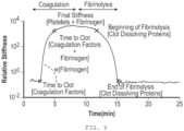
- This curve characterizes hemostasis and can be further processed to estimate direct indices of hemostatic function (See, e.g., FIG. 9 ).
- Other curves, using other reagents, may also be employed to facilitate estimation of, or separately determine, the hemostatic indices.
- Indices of hemostasis are calculated by fitting a sigmoidal curve to the stiffness-time curve and evaluating the first derivative of the curve as described in Mauldin FW, Viola F et al. Adaptive force sonorheometry for assessment of whole blood coagulation. Clinical Chimica Acta 2010; 411 :638-644 .
- the times to clot TC 1 and TC 2 are calculated based on a threshold value of the derivative curve (20% of the minimum value), and are indicative of the beginning and ending phase of fibrin polymerization.
- the clotting slope CFR is the maximum of the derivative curve and is indicative of the rate of fibrin polymerization.
- an angle ⁇ can be defined as the slope of the line between TC 1 and TC 2 .
- the stiffness S is estimated from the stiffness curve 3 minutes after TC 2 . S depends upon platelet function and the final stiffness of the fibrin network. Identical methods and indices are calculated for the fibrinolytic process. In particular the times TL 1 and TL 2 can be defined to represent the initial and final phases of the fibrinolytic process and the consequent dissolution of the fibrin network (time to lysis).
- test well 1 might have kaolin powder to activate coagulation through the intrinsic pathway.
- Test well 2 might have a combination of kaolin and abciximab (ReoPro) to inhibit platelet aggregation.
- Test well 3 might have abciximab and thrombin to activate coagulation through the common pathway.
- Test well 4 might have tissue factor to activate coagulation through the extrinsic pathway.
- Blood samples were obtained from a peripheral vein of the arm of a patient into six 1.8 ml Vacutainers (Becton Dickinson, Franklin Lakes, NJ) containing 3.2% (0.105M) sodium citrate to prevent coagulation within the tubes. The first tube was discarded, while the remaining tubes were placed on a rocker table and analyzed sequentially starting thirty minutes after the draw. For all the experiments described here, samples were obtained from a total of eight volunteers (four male and four female) with age range of twenty-three to thirty years (mean and standard deviation of 25.75 ⁇ 3.3 years) and with no history of thrombotic or hemorrhagic disorders. Ultrasound pulses having 10 Mhz center frequency were applied, pulse repetition frequency (PRF) was adaptively adjusted with the range of about 25 Hz to about 12.8 kHz. Automated measurements having a one second acquisition time were performed every six seconds.
- PRF pulse repetition frequency
- Gly-Pro-Arg-Pro was obtained from Calbiochem (EMD Chemicals Inc., Gibbstown, NJ) with 99.1% purity as determined by HPLC. GPRP was dissolved in PBS into 100 mM stock. Kaolin was obtained in powder form (Sigma Aldrich, St. Louis, MO) and suspended in sterile sodium chloride solution (Becton Dickinson, Franklin Lakes, NJ). Monoclonal antibody abciximab (ReoPro, Eli Lilly and Company, Indianapolis, IN) was obtained in a concentration of 2 mg/ml. The original solution was diluted by a factor of five by adding 200 ⁇ L of PBS into 50 ⁇ l of the original ReoPro solution. The serine protease abbokinase (urokinase-type Plasminogen Activator, or uPA, Hyphen Biomed, Neuville-sur-Oise, France) was obtained in a concentration of 1 unit/ ⁇ ).
- Pulse-to-pulse time delays were estimated using a spline-based estimator as described in Viola F, Walker WF.
- the value of the induced displacement at 1 second was extrapolated from each curve, and the extrapolated displacement values were then normalized by their corresponding PRF and combined to form a stiffness vs. time curve similar to that shown in FIG. 9 .
- Fibrin is the building block of blood clots. Blood samples from 5 volunteers were obtained and the Gly-Pro-Arg-Pro (GPRP) peptide was added in titrated quantities to achieve final concentrations of 0, 1, 2, 4, and 8 mM.
- GPRP Gly-Pro-Arg-Pro
- GPRP is a strong inhibitor of fibrin polymerization that blocks the sites located in the ⁇ chains at the two D end domains of the fibrinogen molecule, as described in further detail by Laudano et al., Studies on synthetic peptides that bind to fibrinogen and prevent fibrin polymerization. Structural requirements, number of binding sites, and species differences.
- Abciximab is a potent inhibitor of platelet aggregation that prevents platelets from binding to fibrinogen by blocking the IIb/IIIa receptor on the platelet's surface, see The EPIC Investigators, "Use of monoclonal antibody directed against the platelet glycoprotein IIb/IIIa, receptor in high-risk coronary angioplasty", N. Engl. J. Med. 1994; 330:956-961 and Collier et al., "A murine monoclonal antibody that completely blocks the binding of fibrinogen to platelets produces a thromastenic-like state in normal platelets and binds to glycoproteins IIb and/or IIIa'', J. Clin. Invest. 1983; 72:325-338 .
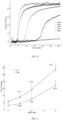
- the resulting sonorheometry curves demonstrate that increasing inhibition of platelet aggregation reduces the stiffness S MAX yielding a softer clot, as shown by curves in FIG. 14 , which correspond to concentrations of abciximab in the samples of 0, 2, 4, 6, 8, and 12 ⁇ g/ml, respectively.
- the other parameters describing the dynamics of clot formation and dissolution did not change significantly, but fell within the intrinsic variability.
- Final clot stiffness varied by over one order of magnitude across the concentrations used for this experiment.
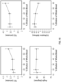
- FIG. 15 shows percentage changes in S MAX as a function of abciximab concentration.
- the results of the experiments and plots shown in FIGS. 14 and 15 suggest that the final stiffness of the clot resulted from the interaction of aggregated platelets and fibrin network.
- the stiffness parameter S MAX is thus indicative of the combined mechanical functions of the fibrin network and the platelet aggregation/contractile function.
- the ability of sonorheometry to characterize platelet aggregation is thus useful, for example, to determine the efficacy of therapies based on Plavix ® or non-steroidal anti-inflammatory drugs (NSAIDs) and to discriminate responders from non-responders to these drugs.
- NSAIDs non-steroidal anti-inflammatory drugs
- Urokinase type plasminogen activator is a serine protease that promotes dissolution of the fibrin network that forms the blood clot, see Lijnen et al., "The mechanism of plasminogen activation and fibrin dissolution by single chain urokinase-type plasminogen activator in a plasma milieu in vitro", Blood 1989; 73:1864-1872 .
- Total amounts of urokinase were 0, 100, 150, and 200 Units per ml of blood, respectively.
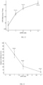
- Urokinase shows significant effects on the measurements performed by sonorheometry, as indicated by the relative stiffness curves in FIG. 16 that correspond to total amounts of urokinase of 0, 100, 150 and 200 Units per ml of blood sample, respectively.
- the blood samples returned to a viscous fluid significantly faster with increasing concentrations of urokinase, as expected.
- Both clot lysis times TL 1 and TL 2 decreased as a function of urokinase concentration, as illustrated in FIG. 17 .
- FIGS. 16 and 17 show that the increased fibrinolytic activity caused by urokinase rapidly dissolved the blood clot and restored the original mechanical conditions prior to clot formation.
- the results in FIGS. 16 and 17 suggest that the parameters TL 1 and TL 2 can be used to characterize dysfunctions of the fibrinolytic system, such as in the case of hyperfibrinolysis.
- the intrinsic variability of sonorheometry was tested using whole blood samples from five volunteers. For each subject, ten samples were obtained into 1.8ml Vacutainers (with 3.2% sodium citrate) and analyzed sequentially using kaolin activation. The estimated coefficients of variation were below 6% (averages over the five subjects) for all of the parameters described above, except LT 1 and LT 2 (the coefficient of variation for LT, and LT 2 were not estimated since clot lysis was not observed within the experiment time of fifteen minutes).
- HCT hematocrit
- An integrated ultrasonic system of the present invention can provide measurements of HCT, hemoglobin concentration (HGB), mean corpuscular volume (MCV), red cell count (RBC), total protein concentration (TPC), mean cellular hemoglobin (MCH), and mean cellular hemoglobin concentration (MCHC) and use those measurements for correcting or adjusting clotting parameters.
- HCT hemoglobin concentration
- MCV mean corpuscular volume
- RBC red cell count
- TPC total protein concentration
- MCH mean cellular hemoglobin
- MCHC mean cellular hemoglobin concentration
- Ultrasound measurements of HCT and related parameters may include backscatter-measuring energy reflected from a blood sample, attenuation coefficient--measuring energy attenuation per unit length through a blood sample, speed of sound--measuring the speed of sound through a blood sample, frequency analysis--measuring the response of the blood chamber to ultrasound at more than one frequency.
- the equipment preferably includes, or duplicatively uses from the prior embodiments, an electronics subsystem and a hardware subsystem.
- the electronics generate the signal burst and record and analyze the resulting echoes.
- the hardware contains the sample and maintains alignment of the various components.
- the HCT measurement aspect of the apparatus includes, or duplicatively uses from the prior embodiments, a sample collection mechanism, sample chamber, transducer, transducer coupling to the sample, and automated signal processing.
- Hematocrit is defined as the volume fraction of red blood cells in a sample of blood.
- the speed of sound in blood is a direct function of the hematocrit (HCT) and a direct function of the amount of hemoglobin in the blood (HGB). This relationship arises because red blood cells and hemoglobin have different material compositions from the surrounding plasma and therefore different speeds of sound.
- the speed of sound of whole blood is approximately the bulk average of the speeds of sounds of its components. In other words, the higher the concentration of red blood cells, the more the speed of sound of the blood will approximate that of red blood cells instead of plasma. Because red blood cells make up nearly 50% of the blood volume, HCT and HGB are by far the strongest drivers the speed of sound. Variations of other blood components (white blood cells, platelets, extra-cellular proteins) may change the speed of sound slightly and limit the accuracy of the measurements, but their influence is small enough that it has not been identified in experiments to date.
- speed of sound is a function of HGB and HCT, one can measure speed of sound and apply it as an indication of the HGB and/or HCT by inverting the calculation.
- the attenuation coefficient in blood is a direct function of the HGB and HCT of the blood because ultrasound attenuates to different degrees in red blood cells than it does in pure hemoglobin or in plasma. This attenuation is caused in part by the viscous losses in the various substances that make up whole blood. The attenuation is also caused in part by the ultrasound scattering off material boundaries such as the membranes of red blood cells. For this reason, the attenuation is also a function of the MCV of the blood, although the relationship is weak enough that in some cases it may be neglected.
- ⁇ f HCT MCV T F ⁇ f HCT T F
- ⁇ attenuation coefficient
- HCT hematocrit
- MCV mean cellular volume
- T temperature
- F frequency
- f a function that can be determined empirically.
- Attenuation coefficient and speed of sound can both be used to independently calculate hematocrit and hemoglobin concentration. Then, the two calculations can be compared for error detection and/or averaged to improve accuracy. Alternatively, the two measurements can be used together to eliminate another common variable such as the distance the sound travels in blood or temperature.
- Backscatter is the acoustic energy reflected from blood. Since this reflection originates almost entirely from scattering off the red blood cells, the backscattered energy is a complex function of the MCV and HCT of the blood sample. However, the function is only monotonic and well behaved for HCT levels below 15%.
- the blood sample first can be diluted to bring the HCT into the linear region below 15% then the device preferably compensates for the dilution in its calculations.
- Bks f HCT MCV T F
- Bks backscattered energy
- HCT hematocrit
- MCV mean cellular volume
- T temperature
- F frequency
- f a function that can be determined empirically. It should be noted that scattering is a "noisy" parameter and may be difficult to measure while speed of sound is a clean measure. Attenuation occurs between the two.
- the backscatter method can also be used in an un-diluted sample though the relationship is more complicated.
- One motivation for measuring backscatter on an undiluted sample is to determine the blood parameters non-invasively by sending and receiving ultrasound into the body.
- the method includes subjecting a whole blood sample to one or more ultrasonic pulses, then measuring the ultrasonic characteristics listed above: (a) backscatter from the blood sample, (b) attenuation of the ultrasonic pulse through the blood sample, or (c) the speed of sound through the blood sample.
- the measurement of (a), (b) or (c) can be used alone or in combination to determine one or more of the related clinical parameters: HCT, HGB, MCV, RBC, MCH, MCHC, TPC.
- the preferable way to calculate speed of sound is by measuring the time of flight of short ultrasonic pulses over a known distance.
- Cf the speed of sound
- d the distance the sound travels through the sample
- t the measured time it takes for the sound to travel that distance.
- the time between transmission and reception is usually considerably longer than the transit time through the sample because it includes delays in the electronics and delays as the ultrasonic wave passes through materials not being studied such as the container walls.
- the transit time through the sample is not measured directly but instead is determined as the difference between two other measurements: the total transit time (which includes both time in the blood and undesired delays) minus the transit time through only undesired delays.
- t blood t total ⁇ t delays where t blood is the transit time the ultrasound takes to travel through the sample, t total is the measured time from send to receive including undesired delays, and t delays is the measured time of all delays except for the transit through the sample.
- One preferable way to measure this time difference is to measure the round trip times of flight from two or more reflectors separated by a known distance along the axis of flight (see FIG. 6 ).
- the ultrasound is broadcast in one beam.
- a portion of the ultrasound echoes from the closer reflector while the rest of the beam continues traveling to echo off the second reflector.
- the difference between these round trip times, divided by two times the distance between reflectors, is the speed of sound in the sample.
- Another preferred embodiment uses a chamber of a precisely known size through which transducers send pulses in pitch-catch mode (see FIG. 8 ). Using pulse-echo measurements from the edges of the chamber allows subtraction of all time delays except the time the sound spent traveling through blood.
- the blood is in a flexible chamber, and time-of-flight measurements are made both before and after deforming the chamber by a known or measurable distance.
- the blood is in a flexible container that fills the space between two precisely located walls. The container material is well controlled such that its time delay is well known and can be subtracted.
- the speed of sound through this flexible wall is roughly matched to the speed of sound through blood, so that the error caused by inaccuracies in estimating the thickness of the wall will negligibly affect the transit time.
- the technique used to measure the attenuation coefficient in blood is similar to the technique used to measure speed of sound.
- the RMS amplitude of the reflections is measured. If a known reflector, the absolute amplitude of the echo will be measured.
- the ratio of the amplitudes from two paths through blood of different lengths is expressed in decibels and divided by the difference of the path lengths.
- A 20 Log V 2 / V1 / D 2 -D 1
- A is the attenuation coefficient in dB/in
- V2 and V1 are the amplitudes of the two received signals
- D2 and D1 are distances the two signals traveled through the sample.
- the speed of sound data and the attenuation coefficient data are usually collected at the same time for each sample. Furthermore, the calculations can be compensated for the temperature of the blood and frequency of the signals.
- the backscatter measurement is performed by analyzing the ultrasonic echo from a diluted blood sample and measuring the RMS voltage of a specified time window within the returned signal.
- the transducer preferably generates a burst containing 2-10 cycles of the center frequency of the interrogating transducer. Energy is reflected back from blood-chamber interface, followed immediately by the energy scattered back by the components of the blood sample. By time gating the RMS measurement to measure the energy scattered by only the sample, and averaging over 50 sampled signals or more, the average backscattered power is measured.
- the clinical parameters may also be determined by exciting the chamber with continuous waves.
- the frequency of this continuous wave is varied slowly to analyze the response of the blood at each frequency.
- a standing wave is set up which indicates that the wavelength is directly related to the chamber's dimensions. Determining the resonant frequencies allows one to calculate the wavelength and correlate that to hematocrit.
- the bandwidth (i.e., fill width at half-maximum) of the resonant frequency peaks is effectively another indication of attenuation. The wider the frequency peak, the higher the attenuation coefficient.
- Other related ultrasonic measurements that provide similar information include the phase shift or amplitude of the signal.
- Acoustic impedance is also an indicator of hematocrit and/or hemoglobin because the acoustic impedance of hemoglobin and other blood constituents is higher than the acoustic impedance of pure plasma. Therefore, higher concentrations of hemoglobin and red blood cells will increase the acoustic impedance of the overall substance from that of pure plasma. Acoustic impedance can be calculated by measuring how much ultrasound is reflected from an interface. If the acoustic impedance of the blood matches the acoustic impedance of the container wall, then no ultrasonic energy will be reflected from the interface. The more the mismatch of acoustic impedances, the more energy will be reflected from the interface. The apparatus preferably lyses the red blood cells before implementing this method to ensure that the hemoglobin and other blood constituents are evenly distributed throughout the blood and along the material interface being used to measure acoustic impedance.
- the refraction angle of the ultrasonic wave at a material interface is an indicator of speed of sound as shown by Snell's Law. Therefore, refraction angle will be directly affected by the physiological hematocrit and/or hemoglobin.
- One preferred way to implement the refraction measurement is to send ultrasound through a triangular blood container that acts as a "prism.” The ultrasonic wave enters the blood perpendicular to the container surface. But, because of the triangular shape of the container, the ultrasound strikes the far wall of the chamber at a known angle of incidence. According to Snell's law, the wave will then travel through the container wall at a angle that depends on the speed of sound in the blood.
- the electronics preferably include means for signal generation, signal capture, and analysis.
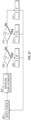
- the electronics are responsible for four functions (shown in FIG. 5 ): generating a precisely controlled signal, sending and receiving the ultrasonic waves, analyzing the received waves, and computing the clinically-relevant results. These functions are divided into the input stage and the receiving stage. Each stage may exist as a separate device, or preferably, some or all of the stages may be integrated together as a single component.
- the sending stage preferably includes a programmable signal generator, signal conditioning components (to amplify, filter, and/or reduce noise), and a power amplifier.
- the signal generator functions to generate one or more acoustic signals.
- the signals may be a gated sinusoid, square pulse, spike with exponential delay or other function.
- the signal normally would have a center frequency matched to the center frequency of the transducer in use to maximize the amount of energy delivered to the sample. For frequency sweeps, the frequency range is preferably chosen to lie within the usable bandwidth of the transducer.
- the pulse generator will preferably generate an electronic pulse to operate the transducers in pitch-catch or pulse-echo mode.
- the frequency of the signal may be from 1 to 50 Mhz, preferably from 5 to 20 Mhz, depending on the type of measurement being made. Higher frequencies could be chosen if the sound is only traveling a short distance through blood in order to increase time resolution or to achieve wavelengths proximate in length to a red blood cell diameter. Lower frequencies could be chosen for long paths to minimize attenuation.
- the burst length may, for example, be 0-5 cycles, most particularly preferably 1-2 cycles for speed of sound and attenuation coefficient measurements.
- the amplitude of the signal generator is preferably maintained at a setting sufficient to provide high-signal-to-noise ratio.
- the signal from the input stage is passed to the transducer.
- the transducer(s) are preferably high efficiency, single element transducers. A variety of commercially available transducers are suitable for use in the apparatus. Each transducer may be selected to match the chamber geometry based on the center frequency, bandwidth, focusing, sensitivity, and beam pattern. For backscatter measurements, the range of frequencies is selected to include values both above and below the 15 MHz threshold for Rayleigh scattering. Preferred interrogating frequencies include 6.5, 10, 20, 30, and 40 MHz. In general, higher frequencies are preferable if the sound is only traveling a short distance through blood in order to increase time resolution and narrow the acoustic beam. Lower frequencies are preferable for long paths to minimize attenuation.
- the, transducer element diameter is preferably selected to ensure that the beam angles are appropriate for the shape of the chamber.
- the beam widths should be narrow enough to minimize the chance of undesired sound paths interfering with the measurement.
- the element diameter affects the distance the transducer can be from the sample (far field distance). Focused transducers may help reduce beam width and far-field distance. Some preferred transducer diameters include 3 mm, 6 mm, and 12 mm.
- the transducers may be used in pulse echo mode and/or in pitch catch mode depending on how they are arranged relative to the chamber. Measuring the time difference between paths or between these two operating modes can eliminate unknowns such as the delays in the electronics or sample holder.
- An annular array of transducers could be used to enable a deeper depth of field.
- the signal returned from the sample causes the transducer to generate an electrical signal that is passed along to the receiving stage.
- the receiving stage preferably includes signal conditioning, an amplifier, a digitizer, and a means for collecting and analyzing data, such as a microprocessor or microcontroller and RAM, magnetic storage or CD (see FIG. 7 ). In this configuration, signal measurements and calculations including transit times and amplitude are calculated based on the digitized signal by the microprocessor.
- Another preferable receiving stage configuration includes signal conditioning, an amplifier, an analog peak detect circuit and a timing circuit.
- the peak detect circuit is used to measure the signal peak amplitude and the timing circuit is used to determine the time from signal transmission to receipt.
- the amplifier is used to bring the signal amplitude up to a level that can be readily captured by a digitizer and/or analyzed by analog electronics. Therefore, the amplifier should be chosen to have the needed gain. The amplifier should also be chosen to have the appropriate bandwidth for the planned measurements.
- the amplifier(s) may also include one or more filters built-in. The filters are used to eliminate noise that lies outside the frequency band being measured. Suitable filters include active and passive filters, RC filters.
- the HCT detection aspect also preferably includes appropriate device control, signal processing and detection logic.
- Device control may be through an on-board processor, programmable logic controller or through discrete logic blocks.
- the signal processing algorithms preferably include one or more of the following: analog and digital noise filtering, averaging, gating and automatic gain control.
- Detection logic may include zero-crossing detection, which automatically measures the exact time a signal crosses zero in order to calculate the transit time of a signal, and amplitude or power measurement.
- a time delay estimation method similar to that used for motion estimation under radiation force, could also be used.
- Hardware preferably includes the sample chamber and transducer.
- the sample chamber or holder is designed to contain the blood sample, allow for stirring of the sample (in the case of backscatter measurements), and maintain alignment and distance between the transducer and the sample. Stirring could be performed by using high intensity pulses to generate acoustic radiation force induced streaming.
- the chamber is actually a segment of a tube through which the blood flows continuously (ex-vivo).
- the chamber is made of flexible materials such as rubber so the blood sample's size or shape can be controlled or adjusted.
- the blood chamber may comprise the patient's body itself in the case of an in-vivo or non-invasive measurement.
- the collection means includes allowances for making live blood draws.
- the collection method may be an off the shelf syringe, off the shelf lance, or custom device which acts as a collection device and a sample chamber combined.
- the chamber may be a tube through which the blood flows.
- the sample chamber is preferably disposable and compact.
- Preferred sample chamber materials include glass, polystyrene, polyamide, polyvinylchloride, silicone, polypropylene, latex or polyethylene.
- the chamber and/or added reflectors are preferably manufactured to precisely known dimensions so that the sound path length is preferably known to +/-0.2%, more preferably to +/-1-0.05%, which ranges include +/-0.1 5, 0.125, 0.1, 0.09, 0.075, and 0.065%.
- a precisely-known path length is preferred to more accurately calculate speed of sound from measuring the time of flight. If the chamber cannot be accurately manufactured, then the path length is preferably measured either by the apparatus itself or by an independent device. The results from said independent device would preferably be fed into the apparatus automatically by a means such as barcodes.
- the sample chamber and/or apparatus parts in acoustic contact with the blood and/or sample chamber preferably has a speed of sound matched to the speed of sound in blood between 1000 m/s and 2500 m/s, which range includes 1200, 1400, 1600, 1800, 2000, 2200, and 2400 m/s.
- Preferable materials include plastic, rubber, aluminum, and combinations thereof.
- the sample chamber preferably holds 0.05 to 10 mL of blood, which range includes 0.075, 0.1, 0.3, 0.5, 0.7, 0.9, 1, 2, 3, 4, 5, 6, 7, 8, and 9 mL of blood.
- the temperature of the sample may be measured directly or indirectly. Indirect means may include waiting for the sample to equilibrate with its environment and measuring the ambient or container temperature in lieu of the blood temperature. If the temperature of the blood is changing rapidly (because it has been freshly drawn for example) repeated ultrasonic measurements allow the apparatus to infer a trend and predict what the final readings would be once the sample has reached thermal equilibrium with its surroundings. Since speed of sound in any apparatus or container changes with respect to temperature, the temperature of the container walls can be inferred by measuring the speed of sound through the walls. The temperature may also be controlled (such as by a temperature controller shown in FIG. 7 ) so that no temperature variations affect the measurement.
- the sample chamber and collection means can also be combined into a single component, wherein the blood sample is collected in the collection means, which then acts as the sample chamber upon which the ultrasound method is used.
- the collection means and sample chamber may comprise a tubular arrangement such that the blood is collected from the patient using a venipuncture needle or other needle device, whereupon the blood flows through a length of tubing.
- the length of tubing can act as the sample chamber, particularly for the attenuation coefficient and speed of sound measurement methods performed on a sample flowing through the length of tubing. Backscatter based methods are less desirable using a flowing sample due to movement of the red blood cells through the tube.
- a calibration can be obtained using samples of independently measured hematocrit, permitting the measurement of the HCT, MCV and/or RBC of the sample, even when flowing through the sample chamber.
- One preferred sample chamber embodiment includes a single or dual element transducer that projects beam(s) through the blood sample, returning reflections from a stepped reflector at the other end of the sample chamber (see FIG. 6 ). The difference in round trip time from these steps can be used to calculate the speed of sound in the test sample.
- the stepped reflector design is preferred in that it has no moving parts, and it is not susceptible to variable time delays outside of the sample chamber, such as transducer couplant delay.
- Another preferred sample chamber includes a small chamber with rigid parallel walls and a depth such that only a few drops of blood can fill the chamber. Sound is transmitted through the chamber along a path perpendicular to the walls as in FIG. 8 .
- Another preferred sample chamber consists of a rubber bladder. This is configured such that when it is placed in the electronics unit and filled with blood, it expands to fill the space between a single fixed transducer and a reflector or between two fixed transducers in the electronics unit.
- the reflector could be inside the chamber or outside. Most preferably, the chamber shape itself would act as the reflector for ease of manufacturing.
- the material of the reflector is not particularly limited.
- the path length difference is likewise not particularly limited, and could preferably range from 1 mm to 10 cm, which range includes 2, 3, 4, 5, 6, 7, 8 and 9 mm, and 1, 2, 3, 4, 5, 6, 7, 8, and 9 cm. Longer paths are preferred for making a more accurate measurement, but shorter paths require less blood. Moving reflectors are possible. In all configurations, vertical ultrasound paths are preferred so that if the red blood cells settle, their average concentration in the beam remains constant.
- the transducers may use liquid or grease as an acoustical couplant to a solid blood container, may be coupled directly to the sample container (dry coupled), or may transmit sound directly into liquid or gas instead of a solid.
- the transducers may be held in a fixture to ensure reliable acoustical coupling to the sample.
- the transducers are disposable and built into the sample chamber. When disposable transducers are integrated into a disposable chamber, the chamber is preferably connected to the test device electrically instead of acoustically.
- the transducers are preferably narrow beam width and more preferably focused to avoid coherent noise caused by stray reflections depending on the geometry of the sample chamber.
- transducers having center frequencies of approximately 1 MHz to 50 MHz, more preferably 5 to 20 MHz may be used. 10 MHz transducers are most preferred, however.
- the higher frequency transducers accommodate a shorter path length and more precise timing.
- a pair of transducers are most preferably used, one on each side of the collected sample as in FIG. 8 .
- test chamber Three types of test chamber are preferable for this device and they all use a drop or several drops of blood. The fact that they use a few drops of blood limits the size of the chamber accordingly.
- the first will be a small capillary tube, preferably capped at one end. This type of tube is similar or identical to that currently used in medical settings as part of a micro-hematocrit test.
- the second preferred embodiment is a sample card, which collects a drop of blood in a small rectangular hole to through which ultrasonic measurements can be made.
- the third preferred embodiment is a sample card, which collects a drop of blood in a flexible thin walled chamber that fills the space between two precisely-located walls within the meter.
- a cartridge could be used with pre-defined wells configured for sample filling using suction, such as the preferred cartridge disclosed in U.S. Patent App. Ser. No. 13/397,398 filed on February 15, 2012 and entitled DEVICES, SYSTEMS AND METHODS FOR EVALUATION OF HEMOSTASIS which is incorporated by reference herein in its entirety.
- This application also discloses preferred hardware and processes for determining hemostasis parameters using multiple samples with different reagents.
- the transducers in this preferred embodiment are preferably in the 10 to 100 MHz range, more preferably 20 MHz. Though the measurement can be made with only one transducer, a pair is most preferably used, one on each side of the collected sample. Locating the pair in this fashion allows both pitch-catch and pulse-echo signals to be measured as shown in FIG. 8 .
- the fixture holding these transducers preferably ensures reliable acoustic coupling between the sample chamber and the transducers.
- the signal generator generates a simple electronic signal of sufficient duration and amplitude to operate the transducers.
- the frequency of the signal is appropriate for the selected transducer, and is preferably from 1 to 3 cycles in length.
- the amplitude of signal should be as high as possible without exceeding the transducers' ratings.
- Another amplifier circuit may be needed to maximize the signal-to-noise ratio.
- this hardware can also determine the relevant clinical parameters using other measurements such as measuring the frequency response of the chamber to determine how much it resonates at each frequency.
- Device control may be through an on-board processor, or through a programmable logic controller that may be shared with the other embodiments for determining clotting parameters.
- the signal processing algorithms preferably include one or more of the following: noise filtering, averaging, and automatic gain control.
- Detection logic preferably includes zero-crossing detection. Zero-crossing detection is a method for accurately measuring the time at which a signal like a wave burst arrives. In this method, the wave is timed by detecting precisely when the signal crosses zero. Because most typical bursts last,several cycles and therefore cross zero multiple times, a single crossing is preferably used consistently in a given application of the method. For example, one embodiment is to use the 2nd (or 3rd or 5th) zero crossing of every burst as the consistent timing point.
- a spline based method or principal component method may also be used as detection logic.
- Another preferred embodiment (B) provides a handheld device suitable for use with a drop of blood and uses disposable transducers. Like embodiment (A), this embodiment, described below, includes a handheld device and will measure hematocrit, the hemoglobin content, and/or the other red blood cell indices. Unlike embodiment (A), though, embodiment (B) preferably includes disposable transducers, which are preferably integrated into the sample chamber.
- test chamber of this embodiment may be in either format described in Embodiment (A) with the exception that the test chambers in Embodiment (B) preferably include one or two disposable transducers built into the test chamber. This chamber with would then use an electrical connection to the test device instead of acoustic coupling.
- disposable transducers may be preferably manufactured using micromachined capacitive elements (MEMS) to minimize cost.
- MEMS micromachined capacitive elements
- the disposable transducers are preferably in the 10 to 100 MHz range, more preferably 20 MHz. A pair of these transducers is preferably used, one on each side of the collected sample. These disposable transducers may or may not be in contact with the drawn blood sample.
- Another preferred embodiment (C), described below, provides a handheld device suitable for use with a tube of blood and using permanent transducers.
- This embodiment varies from (A) and (B) in that a larger volume of blood is used.
- the user draws a tube of blood from the patient via venipuncture.
- the sample is placed into the device and the device displays the hematocrit, the hemoglobin content, and/or the mean cell volume.
- the device is preferably handheld, battery powered, and portable.
- the sample chamber is preferably disposable.
- the test chamber may be a medical tube configured for the introduction of reagents.
- the tube is inserted into the invention and the transducers couple directly to its outside surface.
- Two modes of signal propagation are preferable. In the first, the signals are transmitted perpendicularly to the tube axis and transmit through the tube for pitch-catch measurements and reflect off the walls for pulse-echo measurements as shown in FIG. 8 . In the second mode, the signal travels along the axis of the tube or perpendicularly but reflect from a disposable, two-step reflector of known size that has previously been inserted into the tube as shown in FIG. 6 .
- the measurement is made in-vivo, without drawing any blood from the patient.
- the device is held against the patient's skin and sends ultrasound into the patient.
- the backscatter, speed of sound, attenuation, and other ultrasonic measurements are calculated from the received signals and used to infer the blood properties.
- An array transducer is preferable so that the device can dynamically steer the sound beam and alter the focus length to search for a large artery or vein. If an array transducer is chosen, an appropriate signal generator to control the array and allow the beam-steering is preferred.
- the HCT and associated parameters are used in conjunction with conventional measures of hemostasis, as output by sonorheometry. Variations of HCT level, such as in the case of hemodilution, affect the results of conventional coagulation tests such as the PT, PTT and ACT.
- FIG. 18 shows how sonorheometry parameters TC1, TC2, angle, and estimated stiffness S vary as a function of hemodilution, which causes the HCT to change.
- the data shown in this figure was obtained from whole blood samples from 5 healthy individuals. Increasing amounts of normal saline were added to the whole blood samples to reduce the HCT. Since sonorheometry uses ultrasound signals to perform measurements of hemostasis and the same ultrasound signals can be used to estimated HCT, the parameters output by sonorheometry can be corrected to adjust for the HCT effects shown in FIG. 18 .
- sonorheometry can be further modified to output and display HCT level in addition to the hemostatic indexes presented in Table II.
- Transfusion protocols often use the HCT value as a trigger to transfuse packed red blood cells (RBCs) units. Therefore, in a single device sonorheometry can output a index for (1) coagulation factors (intrinsic and / or extrinsic), (2) platelet function, (3) fibrinogen, (4) fibrinolysis, and (5) HCT so that it can provide guidance for the transfusion of: (1) fresh frozen plasma, (2) platelet concentrates, (3) cryoprecipitate, (4) antifibrinolytics, and (5) packed RBCs, respectively.
- HCT measurements can be used to improve or correct coagulation parameters to be closer to those obtained for plasma measurements such as described by Amukele TK et al. Comparison of Plasma With Whole Blood Prothrombin Time and Fibrinogen on the Same Instrument. American Journal of Pathology 2010 .
- the prothrombin time (PT), international normalized ratio (INR) and fibrinogen viscoelastic assays can vary due to the impact of HCT when in certain ranges.
- the present invention accounts for the impact of HCT by comparing the HCT to an assumed value (if any) or by determining a range in a clotting parameter in which the measured parameter is particularly sensitive to HCT and communicating this to the healthcare personnel.
- the present system or process can use empirically determined relationships characterizing the variation of hemostasis parameters with changes in HCT and other oxygen transport parameters to correct or adjust the estimated hemostasis parameter.
- the system could apply linear regression to empirical data to determine a corrected hemostasis parameter.
- the system could use a higher order curve, such as a parabola, to determine a corrected hemostasis parameter.
- Physiological adjustments as defined herein use the relationships within living or biological systems to correct or adjust measurements. For example, the above-described use of a known physiological relationship between HCT and hemostatic parameters is a physiological adjustment.
- Physical adjustments as defined herein use pure physical principals independent of living systems to correct or adjust measurements. For example, the use of speed of sound to calibrate the applied radiation force is a physical adjustment.
- integrated refers to a system or process that uses common or shared hardware or a common sample. Also, data from the same transmission could be used as a form of integration.
- the system may determine hemostatic and oxygen transport parameters using the same blood sample and/or the same transducer or transducers, or at least common hardware and/or sample portions. Integration therefore reduces the time, cost and complexity of determining these important clinical hemostatic and oxygen transport parameters.
- Prior art systems for example may use a twisting weight supported by a wire to determine clot stiffness. Such systems are incapable of transmitting or measuring sound through a blood sample. Conversely, prior art systems for measuring the speed of sound through blood are incapable of determining hemostatic parameters. They cannot, for example, induce displacements of clots or measure the induced displacement.
- FIG. 26 schematically illustrates the impact of the improved dynamic range on clot stiffness measurements compared to a conventional device.
- the system may also be configured to adapt to or adjust to the characteristics of the clot.
- the adaptation capability can apply a "light touch" to the clot by changing the emitted sound signal to adjust to the properties of the clot. This avoids tearing of the clot.
- the prior art pendulum systems are relatively insensitive to softer clots and/or can tear or damage a clot during testing, distorting the measurements.
- the ability of the integrated system to adapt reduces electronic noise for greater sensitivity to small echoes.
- the present system or device has a relatively high sensitivity throughout the large stiffness range.
- the system is capable of an increased rate of pulses, resulting in greater forces, further expanding the dynamic range.
- the pulse frequency range may, for example, be from 1 Hz to 50 kHz.
- the system or device may be capable of measuring tissue stiffness in a range of five or more (10 5 or greater from softest to hardest) orders of magnitude.
- Another advantage of the system or device is its low number of moving parts compared to prior art mechanical systems that employ weights or cantilevers. These attributes offer another advantage by facilitating miniaturization of the system or device. Also, because the sensing system requires no moving parts, the sensing system performs better when subjected to environment vibrations.
- FIG. 19 An exemplary process or system 200 for integrated determination of one or more hemostasis parameters and one or more oxygen transport parameters is shown in FIG. 19 .
- a consumable cartridge or other container 30 is inserted 202 by the user into the hemostasis system assembly 1.
- a syringe containing a blood sample 51 is then manually attached to the consumable.
- User input is provided 204 to the hemostasis system assembly 1.
- the user may confirm that the consumable 30 is in place by pressing a "start" button.
- Other input may be provided that facilitates or improves determining of the parameters.
- the input may include identification of the patient associated with the sample.
- the device 1 clamps 206 the consumable by applying pressure to the consumable.
- This pressure may form an acoustic coupling between the consumable and an acoustic wave generating transducer or device 10.
- the consumable 30 may include aspects of the acoustic wave generating device 10, such as consumable lenses.
- the consumable 30 is heated 208 to a temperature that facilitates blood coagulation.
- a two-way pumping mechanism of the assembly I draws or aspirates 210 blood from the sample 51 into the consumable 30.
- the blood sample 51 is acoustically mixed 211 with a reagent in a well of the consumable.
- Parameters are measured 212 by repeatedly cycling through data acquisition processes in each transducer channel (e.g., 4 transducer channels) while blood coagulates in the consumable 30.
- Data is acquired 222 and processed 224 from each channel of the transducer 10.
- Each channel may have dedicated acquisition 222 and processing 224 before the system 1 moves on to the next channel.
- Acquisition 222 may include two steps, radiation force (RadFor) data acquisition 226 and calibration data acquisition 228.
- radiation force data acquisition 226 includes transmission of an ensemble of relatively high intensity acoustic pulses into the blood sample.
- the system 1 receives acoustic echo data back from each individual pulse or from a selected subset of the transmitted pulses.
- Each ensemble of acoustic pulses may be adaptively controlled.
- Calibration data acquisition 228 includes transmission of a single acoustic pulse that targets the back of the consumable 30. From this pulse the system 1 derives values for the speed of sound in the blood sample and the acoustic attenuation. More details about radiation force data acquisition 226 and calibration data acquisition 228 are described below.
- Acquired data is processed 230 by application of several sub-processes, including estimating stiffness 232, estimating HCT (or other oxygen transport parameter) 234, updating the configuration 236, estimating signature parameters 238 and estimating indices 240.
- Estimating stiffness 232 includes accepting raw data acquired from the radiation force acquistion 226 and processesing it to yield a single stiffness estimate based on the transmitted radiation force ensemble parameters and the calibration parameters.
- Estimating HCT 234 includes deriving a speed of sound and acoustic attenuation from the calibration data acquisition 228 by applying a mathematical model.
- the estimation sub-process could use a linear mathematical model correlating the speed of sound to hematocrit.
- Update the configuration 236 is part of the adaptive acoustic system and includes accepting the maximum displacements acquired during radiation force acquisition 226 and the transmitted ensemble configuration to determine the configuration that will be used for the next ensemble of pulses.
- the adaptive process is described in more detail below.
- Estimating signature parameters 238 includes accepting the single stiffness value from the estimating stiffness 232 sub-process into a matrix containing all of the measured stiffness values for that channel. This sub-process combines all of the stiffness data acquired thus far and fits a non-linear curve to the data.
- the signature parameters are determined from the non-linear curve.
- the signature parameters for example, are the baseline stiffness, time to clot, rate of clot formation, time to lyse, post-lysis stiffness.
- Estimating indices 240 includes computing hemostatic indices based on the signature parameters.
- the acquisition 222 and processing 224 steps are cycled continuously for each of the four channels until the blood coagulation process is complete.
- each of a plurality of channels is configured to transmit Tx and receive Rx sonic energy to determine a point on a time displacement curve.
- the four channels generate four transmissions Tx0, Tx1, Tx2, Tx3 and receive four signals Rx0, Rx1, Rx2, Rx3.
- the acquired data is then filtered to determine a time-displacement curve at four equal periods, a shown in FIG. 24 .
- Filtration for example, may be by a principal components filter, such as is described in U.S. Patent Application Publication No. 2009/0304246 to Walker et al . entitled REDUCTION OF ECHO DECORRELATION FACILITATING MOTION ESTIMATION which is incorporated by reference herein in its entirety.
- the filtered points are then curve fit using a model, such as a viscoelastic model described above, to estimate a displacement at a time of interest. For example, displacements could be determined at a one second time interval.
- Stiffness could be calculated at various intervals depending upon available or desired use of computational power. For example, a 6 second interval yields fairly robust curves while conserving processing power.
- the applied force can be adjusted by changing the PRF.
- the sensitivity could also be adjusted by changing the time at which the displacement is projected, such as to 1/2 second from 1 second.
- FIGS. 27 and 28 show a principle and process of applying adaptive force to a sample for high dynamic range measurement performed at low strain levels according to an embodiment of the present invention.
- FIG. 27 is a flow chart illustrating an example of the principle of applying adaptive force to a sample for high dynamic range measurement performed at low strain levels according to an embodiment of the present invention.
- a minimum displacement threshold level "a" and a maximum displacement threshold level “b" are preset prior to application of force.
- force F is applied to the target being measured according to an embodiment of the present invention.
- a displacement of the target that resulted from application of the force F to the target in event 302 is measured.
- the measured displacement is compared to the minimum displacement threshold level "a".
- the force F is increased at event 308 (e.g., doubled, in the embodiment shown in FIG. 2 ) and this greater force is then applied at event 302 to take the next measurement at event 304.
- the force is reduced at event 312 (e.g., halved, in the embodiment shown in FIG. 2 ) and this lesser force is then applied at event 302 to take the next measurement at event 304. If, on the other hand, the measured displacement not greater than "b", then the force is maintained at its current level at event 314 and the same force is applied at event 302 for taking the next measurement.
- an increase of the force F may be accomplished by increasing the PRF.
- a decrease of the force F may be achieved by decreasing the PRF.
- the present invention can carry out sonorheometry at low strains with a dynamic range of stiffness measurements of approximately five orders of magnitude.
- the present invention is not limited to increasing by doubling or decreasing by half, as any arbitrary multipliers can be implemented to carry out the described principle.
- Possibilities include greater than one for increasing, and less than one, but greater than zero, for decreasing.
- increasing and decreasing functions need not be limited to changing the PRF. They can alternatively be carried out by changing the pulse intensity integral (PII) or by changing both PRF and PII.
- PII pulse intensity integral
- FIG. 28 is a flow chart illustrating use of adaptive radiation force sonorheometry to adaptively adjust the applied radiation force in order to maintain low strains and improve dynamic ranges (thereby increasing the signal to noise ratio) of stiffness measurement according to an embodiment of the present invention.
- initial parameters are set for PRF and PII, thus defining the initial pulse generation parameters.
- the initial PRF is set at a value with the range of from about 4 Hz to about 12 kHz, or less than or equal to 100 Hz, although the present invention is not limited to these settings. Pulses with as little as one cycle up to pulses with sixteen or more cycles can be used. Amplitude may be varied such as increasing (up to doubling, or more) or decreasing (down to halving, or less). In cases where an emission transducer of relatively low efficiency is used, PRF and PII may be set relatively higher. For applications to plasma, which has a lower viscosity than whole blood, relatively lower PII and PRF may be set. Also, when examining plasma, it may be necessary to add an acoustic scattering agent, such as polystyrene microspheres.
- an acoustic scattering agent such as polystyrene microspheres.
- acoustic radiation force pulses are transmitted to the target according to the PRF and PII that were initially set in event 402.
- a displacement of the target is estimated or measured by sonorheometry, using echoes returned from the target.
- the estimated displacement value is compared with the maximum displacement threshold value "b". If the estimated displacement value is greater than "b", then the force to be applied to the target in the next iteration is set to be decreased by decreasing the PRF and/or decreasing the PII at event 414 and a relative stiffness value (or absolute stiffness value in embodiments where the constants a and c are measured) is computed at event 412, using the estimated displacement value.
- event 404 is carried out again by transmitting decreased force generated using the parameters from event 414.
- the estimated or measured displacement value is not greater than "b" at event 408, then at event 410 the estimated displacement value is compared with the minimum displacement threshold value "a". If the estimated displacement value is less than "a", then the force to be applied to the target in the next iteration is set to be increased by increasing the PRF and/or increasing the PII at event 416 and a relative stiffness value (or absolute stiffness value in embodiments where the constants a and c are measured) is computed at event 412, using the estimated displacement value.
- event 404 is carried out again by transmitting increased force generated using the parameters from event 414. Iterations can be carried out until all physiological observations that the observer is interested in have been made, e.g., until an experiment is ended, until a patient is released to another care center, until a clot completely dissolves, etc.
- the systems of FIGS. 27 and 28 may include a curve comparison step in place of, or in addition to, or as part of, steps 306, 310, 408 or 410.
- This curve displacement step compares the measured time-displacement curve to an expected model curve. The fit of the measured curve to the expected model curve is quantified. If it is below the threshold the force is reduced. Without being wed to theory, the assumption is that the poor fit is because large displacements are causing signal decorrelation. Sensitivity is related to the amount of force applied to the sample, which results in higher displacements.
- short pulses also do not smear as much due to the lack of overlap in the return signal.
- the overall amplitude of the response may be somewhat small.
- the return signal amplitude could be increased through an increase in the amplitude of the transmitted pulse.
- power limitations can curtail the size of the amplitude, especially in systems where the peak-to-peak power potential is limited to 200V because of the electronic components used. Longer pulses may result in a stronger "push" also, but can result in smear due to overlap in the return signal.
- the present system and device may include processes for ameliorating the smear effects.
- coded excitation could be used to improve force measurement and imaging.
- Radiation force based sensing is limited by the available signal to noise.
- the fundamental signal is radiation force induced displacement.
- the noise is the error in estimation of that displacement.
- PRF pulse repetition frequency
- W PRF ⁇ PII
- the PRF can be greatly increased to increase force applied to the sample. Power increases, however, may be limited. Application of a high PRF may cause echoes from earlier pulses to overlap in time with the desired echoes from the most recently transmitted pulse. This makes it difficult to cleanly estimate displacement. Further, if the PRF is too high then it becomes challenging to transfer the digitized echo data from one transmission before echo data is digitized from the following transmission. For these reasons it is desirable to increase the power per transmitted pulse (Pulse Intensity Integral).
- the PII in each transmitted pulse is proportional to the integral of the square of the acoustic pressure in that pulse.
- a first strategy is to increase the amplitude of the acoustic pulse. This can be accomplished by increasing the drive voltage of the transmit circuit. However, the circuitry of the emitter is usually limited to +/- 100V to avoid damage.
- the length of the emitted pulse could also be increased. One would maintain the same center frequency but increase the number of cycles in the transmission. This approach however will reduce the signal bandwidth and the axial resolution of the system. These changes may reduce the available window for measuring displacement by overlapping the desired region with signals from the undesired region. Further, the accuracy of displacement estimates is reduced as described by the Cramér-Rao Lower Bound.
- the radiation force sensing could be improved if pulse length could be increased without degrading the axial resolution or bandwidth, such as by using coded excitation.
- coded excitation For example, Barker Codes could be used. Barker codes are simple binary codes that have the property of having very short correlation lengths when convolved with the proper matched code. These codes preserve bandwidth and spatial resolution while still lengthening the transmitted pulse.
- FIG. 20 For example, a two-cycle transmit pulse is shown in FIG. 20 .
- the associated correlation function shown in FIG. 21 is quite short, indicating that good spatial resolution in maintained. It is also quite low in amplitude however, indicating fairly low transmit energy.
- the original two cycle transmit pulse is replaced by a version of that pulse convolved with a 5 sample Barker code (+ + + - +).
- the transmitted pulse is now five times longer, generating a significantly higher (5x) peak in the autocorrelation function.
- the transmission is much more energetic.
- the correlation function itself however remains quite short in duration, as shown in FIG. 23 , indicating that axial resolution is largely preserved. Modest ringing is introduced, but this is a reasonable tradeoff for the large increase in displacement that will be achieved.
- improving dynamic range may be a matter of incrementally improving the electronic signal-to-noise, increasing the applied force at one end (high stiffness) and reducing the applied force at the other end (low stiffness).
- At the low end may be a 2 cycle transmission at 4 Hz PRF.
- At the high end a 13 point barker code with 2 cycle impulse response for a 26 cycle transmit at 32 KHz PRF may be employed.
- the high to low force variation is by a factor of 212,992.
- the present system or device can also improve sensitivity through the use of multiple samples. For example, four wells with different reagents could be used to determine measurements within overlapping time periods.
- HCT oxygen transport parameters
- FIG. 25 shorter pulses are generated during calibration resulting in a delayed response compared to the echoes returned by the blood. This may be due to the further distance of the back wall of the sample container, for example.
- the system or device is configured to measure, including amplitude and time, from both the blood and the back wall of the container.
- FIG. 19 a schematic diagram of a central server 500, or similar network entity, configured to implement a system or process disclosed herein is provided.
- central merely serves to describe the common functionality the server provides for multiple clients or other computing devices and does not require or infer any centralized positioning of the server relative to other computing devices.
- the central server 500 may include a processor 510 that communicates with other elements within the central server 500 via a system interface or bus 545. Also included in the central server 500 may be a display device/input device 520 for receiving and displaying data. This display device/input device 520 may be, for example, a keyboard or pointing device that is used in combination with a monitor.
- the central server 500 may further include memory 505, which may include both read only memory (ROM) 535 and random access memory (RAM) 530.
- the server's ROM 535 may be used to store a basic input/output system 540 (BIOS), containing the basic routines that help to transfer information across the one or more networks.
- BIOS basic input/output system
- the central server 500 may include at least one storage device 515, such as a hard disk drive, a floppy disk drive, a CD Rom drive, or optical disk drive, for storing information on various computer-readable media, such as a hard disk, a removable magnetic disk, or a CD-ROM disk.
- each of these storage devices 515 may be connected to the system bus 545 by an appropriate interface.
- the storage devices 515 and their associated computer-readable media may provide nonvolatile storage for a central server. It is important to note that the computer-readable media described above could be replaced by any other type of computer-readable media known in the art. Such media include, for example, magnetic cassettes, flash memory cards and digital video disks.
- a number of program modules may be stored by the various storage devices and within RAM 530.
- Such program modules may include an operating system 550 and a plurality of one or more (N) modules 560.
- the modules 560 may control certain aspects of the operation of the central server 500, with the assistance of the processor 510 and the operating system 550.
- the modules may perform the functions described above and illustrated by the figures, such as FIGS. 19 , 27 and 18 , and other materials disclosed herein.
- the modules may include, for example, an acquisition module 570 and a processing module 580 for performing the operations described in reference to FIG. 19 .
- each block in the flowchart or block diagrams may represent a module, segment, or portion of code, which comprises one or more executable instructions for implementing the specified logical function(s).
- the functions noted in the block may occur out of the order noted in the figures. For example, two blocks shown in succession may, in fact, be executed substantially concurrently, or the blocks may sometimes be executed in the reverse order, depending upon the functionality involved.
Claims (12)
- System (50) zum Bestimmen von Eigenschaften einer Blutprobe, wobei das System (50) umfasst:einen gemeinsamen Probenabschnitt;ein Messsystem, das so konfiguriert ist, dass es die Bestimmung mindestens eines Hämostaseparameters und mindestens eines Sauerstofftransportparameters einer Blutprobe im gemeinsamen Probenabschnitt erleichtert, wobei das Messsystem einen Empfänger (56) umfasst, der so konfiguriert ist, dass er eine durch Kraftanwendung auf die Blutprobe erzeugte Verschiebung der Blutprobe bestimmt, undeinen Prozessor (58), der so konfiguriert ist, dass er Daten, einschließlich der Verschiebung der Blutprobe, vom Messsystem empfängt und unter Verwendung der Daten den mindestens einen Hämostaseparameter und den mindestens einen Sauerstofftransportparameter bestimmt,wobei der mindestens eine Sauerstofftransportparameter aus einer Gruppe bestehend aus HCT, HGB, MCV, RBC, MCHC, MCH und Kombinationen davon ausgewählt ist,wobei das Bestimmen des Hämostaseparameters das Anpassen des Hämostaseparameters unter Verwendung des Sauerstofftransportparameters umfasst,wobei das Messsystem umfasst:einen Ultraschallsignalgenerator, der so konfiguriert ist, dass er ein Ultraschallsignal erzeugt und leitet, um mit der Blutprobe zu interagieren und dadurch die Kraft auf die Blutprobe auszuüben; undwobei der Empfänger (56) so konfiguriert ist, dass er mindestens ein Merkmal des Ultraschallsignals bestimmt, das mit der Blutprobe interagiert hat, wobei das Merkmal Daten umfasst.
- System nach Anspruch 1, wobei der Hämostaseparameter aus der Gruppe bestehend aus TC1, TC2, Winkel, geschätzter Steifigkeit S, Basisviskosität und Nachlyseviskosität ausgewählt ist.
- System (50) nach Anspruch 2, wobei der Hämostaseparameter ein Index für einen klinischen Parameter ist, der aus der Gruppe bestehend aus (1) Gerinnungsfaktoren (intrinsisch und/oder extrinsisch), (2) Thrombozytenfunktion, (3) Fibrinogen und (4) Fibrinolyse ausgewählt ist.
- System (50) nach Anspruch 2, wobei der Prozessor so konfiguriert ist, dass er den klinischen Parameter übermittelt, und der klinische Parameter so konfiguriert ist, dass er die Transfusion von mindestens einem aus der Gruppe bestehend aus (1) frisch gefrorenem Plasma, (2) Blutplättchen-Konzentrate, (3) Kryopräzipitat, (4) Antifibrinolytika und (5) gepackte RBCs steuert.
- System (50) nach einem der vorhergehenden Ansprüche, wobei das Bestimmen des Hämostaseparameters die Quantifizierung der in der Blutprobe induzierten Verschiebung durch Anwendung mindestens eines Ultraschallimpulses ausreichender Intensität umfasst, um eine messbare Verschiebung in der Blutprobe zu induzieren.
- System (50) nach Anspruch 5, wobei der Prozessor (58) so konfiguriert ist, dass er unter Verwendung der Verschiebung eine Steifigkeit der Blutprobe bestimmt und die Steifigkeit zum Bestimmen des Hämostaseparameters verwendet.
- System (50) nach einem der vorhergehenden Ansprüche, wobei die Daten die Schallgeschwindigkeit durch die Blutprobe umfassen und wobei der Prozessor (58) so konfiguriert ist, dass er die Schallgeschwindigkeit verwendet, um den Sauerstofftransportparameter zu bestimmen.
- System (50) nach einem der vorhergehenden Ansprüche, wobei die Daten eine Dämpfung des Ultraschallsignals durch die Blutprobe umfassen und wobei der Prozessor (58) ferner so konfiguriert ist, dass er die Dämpfung verwendet, um den Sauerstofftransportparameter zu bestimmen.
- System (50) nach einem der vorhergehenden Ansprüche, wobei die Daten die Rückstreuung des Ultraschallsignals von der Blutprobe umfassen und wobei der Prozessor (58) ferner so konfiguriert ist, dass er die Rückstreuung verwendet, um den Sauerstofftransportparameter zu bestimmen.
- System (50) nach Anspruch 2, wobei der Prozessor (58) so konfiguriert ist, dass er den klinischen Parameter übermittelt, um die Transfusion zu steuern.
- System (50) nach Anspruch 2, wobei der Prozessor (58) so konfiguriert ist, dass er den HCT oder einen zugehörigen Parameter meldet.
- System (50) nach Anspruch 1, ferner umfassend eine grafische Benutzeroberfläche, die so konfiguriert ist, dass sie sowohl den mindestens einen Hämostaseparameter als auch den mindestens einen Sauerstoffparameter gleichzeitig anzeigt.
Applications Claiming Priority (2)
| Application Number | Priority Date | Filing Date | Title |
|---|---|---|---|
| US201161443084P | 2011-02-15 | 2011-02-15 | |
| PCT/US2012/025278 WO2013105987A2 (en) | 2011-02-15 | 2012-02-15 | Characterization of blood hemostasis and oxygen transport parameters |
Publications (4)
| Publication Number | Publication Date |
|---|---|
| EP2676143A2 EP2676143A2 (de) | 2013-12-25 |
| EP2676143A4 EP2676143A4 (de) | 2017-01-04 |
| EP2676143B1 true EP2676143B1 (de) | 2023-11-01 |
| EP2676143C0 EP2676143C0 (de) | 2023-11-01 |
Family
ID=46796835
Family Applications (1)
| Application Number | Title | Priority Date | Filing Date |
|---|---|---|---|
| EP12865373.0A Active EP2676143B1 (de) | 2011-02-15 | 2012-02-15 | Charakterisierung von hämostase- und sauerstofftransportparametern |
Country Status (5)
| Country | Link |
|---|---|
| US (4) | US9031701B2 (de) |
| EP (1) | EP2676143B1 (de) |
| AU (2) | AU2012364909B2 (de) |
| CA (1) | CA2826770C (de) |
| WO (1) | WO2013105987A2 (de) |
Families Citing this family (20)
| Publication number | Priority date | Publication date | Assignee | Title |
|---|---|---|---|---|
| US8448499B2 (en) | 2008-12-23 | 2013-05-28 | C A Casyso Ag | Cartridge device for a measuring system for measuring viscoelastic characteristics of a sample liquid, a corresponding measuring system, and a corresponding method |
| US10267769B2 (en) | 2010-03-04 | 2019-04-23 | Ventana Medical Systems, Inc. | Processing system for processing specimens using acoustic energy |
| US10539487B2 (en) | 2010-03-04 | 2020-01-21 | Ventana Medical Systems, Inc. | Systems and methods for monitoring tissue sample processing |
| US10126216B2 (en) | 2011-02-17 | 2018-11-13 | Ventana Medical Systems, Inc. | Method for tissue sample fixation |
| CA2795454C (en) | 2010-04-08 | 2023-04-18 | Hemosonics, Llc | Hemostatic parameter display |
| CA2826770C (en) | 2011-02-15 | 2020-06-23 | Hemosonics, Llc | Characterization of blood hemostasis and oxygen transport parameters |
| ES2854873T3 (es) | 2011-02-15 | 2021-09-23 | Hemosonics Llc | Dispositivos, sistemas y procedimientos para la evaluación de la hemostasia |
| US20120294767A1 (en) | 2011-05-19 | 2012-11-22 | Hemosonics Llc | Portable hemostasis analyzer |
| US10175225B2 (en) | 2014-09-29 | 2019-01-08 | C A Casyso Ag | Blood testing system and method |
| EP3256844B1 (de) | 2015-02-09 | 2021-04-14 | Ventana Medical Systems, Inc. | System und verfahren zur standardisierung der diffusion eines fluids in geweben |
| US10571417B2 (en) | 2015-02-20 | 2020-02-25 | Sony Corporation | Electrical characteristic measurement apparatus, electrical characteristic measurement system, electrical characteristic measurement method, and program for electrical characteristic measurement for causing computer to implement the method |
| US9726647B2 (en) | 2015-03-17 | 2017-08-08 | Hemosonics, Llc | Determining mechanical properties via ultrasound-induced resonance |
| US11366093B2 (en) * | 2017-04-20 | 2022-06-21 | Hemosonics, Llc | Disposable system for analysis of hemostatic function |
| WO2019051000A1 (en) * | 2017-09-05 | 2019-03-14 | Utah Valley University | COMPACT IMMERSION SCAN SYSTEM FOR HIGH FREQUENCY AUDIO WAVES |
| JP7138427B2 (ja) | 2017-11-09 | 2022-09-16 | 株式会社明治 | 固液分布検出装置 |
| US20220018827A1 (en) * | 2018-12-07 | 2022-01-20 | Siemens Healthcare Diagnostics Inc. | Solution collection device with evaluation element |
| CN114113099A (zh) * | 2020-08-28 | 2022-03-01 | 致茂电子(苏州)有限公司 | 自动化调整电子设备的方法 |
| CN112067575A (zh) * | 2020-09-09 | 2020-12-11 | 吴俊� | 血液纤维蛋白溶解功能检测方法 |
| WO2023213415A1 (en) * | 2022-05-06 | 2023-11-09 | Analog Devices International Unlimited Company | Feature extraction from time-based transition events |
| CN115127970B (zh) * | 2022-08-30 | 2022-11-15 | 西南石油大学 | 一种高温高压储层等效井下渗流特征及产能实验模拟方法 |
Family Cites Families (427)
| Publication number | Priority date | Publication date | Assignee | Title |
|---|---|---|---|---|
| JPS5311473B2 (de) | 1974-07-03 | 1978-04-21 | ||
| JPS5130683A (ja) | 1974-09-10 | 1976-03-16 | Okuma Machinery Works Ltd | Naraiseigyosochi |
| US3996791A (en) | 1975-04-24 | 1976-12-14 | Krautkramer-Branson, Incorporated | Ultrasonic test method and apparatus utilizing scattered signals |
| US4105018A (en) | 1976-02-02 | 1978-08-08 | University Of Utah | Acoustic examination, material characterization and imaging of the internal structure of a body by measurement of the time-of-flight of acoustic energy therethrough |
| AU505308B2 (en) | 1976-09-21 | 1979-11-15 | Asahi Glass Company Limited | Glass for use in ultrasonic delay lines |
| JPS5655091Y2 (de) | 1976-09-29 | 1981-12-22 | ||
| CH610111A5 (de) | 1977-01-13 | 1979-03-30 | Contraves Ag | |
| JPS541062U (de) | 1977-06-06 | 1979-01-06 | ||
| US4238725A (en) | 1979-01-15 | 1980-12-09 | The United States Of America As Represented By The United States Department Of Energy | Apparatus for checking the direction of polarization of shear-wave ultrasonic transducers |
| US4248092A (en) | 1979-04-25 | 1981-02-03 | Electric Power Research Institute, Inc. | Method and apparatus for efficiently generating elastic waves with a transducer |
| US4293934A (en) | 1979-06-18 | 1981-10-06 | Shell Oil Company | Circumferential acoustic device |
| US4305294A (en) | 1980-01-10 | 1981-12-15 | Rockwell International Corporation | Ultrasonic apparatus and method for measuring wall thickness |
| JPS56143951A (en) | 1980-04-10 | 1981-11-10 | Nisshin Steel Co Ltd | Ultrasonic flaw detection for austenite alloy steel welded steel pipe |
| US4292848A (en) | 1980-04-11 | 1981-10-06 | Systems Research Laboratories, Inc. | Walking-gate ultrasonic flaw detector |
| US4435984A (en) | 1980-04-21 | 1984-03-13 | Southwest Research Institute | Ultrasonic multiple-beam technique for detecting cracks in bimetallic or coarse-grained materials |
| US4570487A (en) | 1980-04-21 | 1986-02-18 | Southwest Research Institute | Multibeam satellite-pulse observation technique for characterizing cracks in bimetallic coarse-grained component |
| US4814247A (en) | 1983-01-26 | 1989-03-21 | University Of Medicine And Dentistry Of New Jersey | Method for determining the existance and/or the monitoring of a pathological condition in a mammal |
| US4900679A (en) | 1983-01-26 | 1990-02-13 | University Of Medicine And Dentistry Of New Jersey | Method for determining the existence and/or the monitoring of a pathological condition in a mammal and a test kit therefor |
| US4705756A (en) | 1983-01-26 | 1987-11-10 | University Of Medicine And Dentistry Of New Jersey | Method of determining the existence and/or the monitoring of a pathological condition in a mammal |
| US4522064A (en) | 1983-12-12 | 1985-06-11 | Sigma Research Inc. | Ultrasonic method and apparatus for determining the depth of a crack in a solid material |
| US4598973A (en) | 1984-03-07 | 1986-07-08 | Greenleaf James F | Apparatus and method for recording and displaying a three-dimensional image |
| US4559827A (en) | 1984-04-11 | 1985-12-24 | The United States Of America As Represented By The United States Department Of Energy | Ultrasonic shear wave couplant |
| JPS6193952A (ja) | 1984-10-04 | 1986-05-12 | Mitsubishi Electric Corp | 厚肉管の超音波斜角探傷法 |
| US4558589A (en) | 1984-10-09 | 1985-12-17 | Miles Laboratories, Inc. | Ultrasonic coagulation monitor and method |
| US4695956A (en) | 1984-11-01 | 1987-09-22 | Leveen Eric G | Apparatus and method of quantifying hemostasis using oscillations from a transducer immersed in the blood sample |
| US4658827A (en) | 1985-05-31 | 1987-04-21 | Mayo Medical Resources | Ultrasound scanner for tissue characterization |
| US4658649A (en) | 1985-06-06 | 1987-04-21 | Combustion Engineering, Inc. | Ultrasonic method and device for detecting and measuring defects in metal media |
| US4702110A (en) | 1985-06-20 | 1987-10-27 | J. A. Green Company | Method and apparatus for measuring metal hardness utilizing longitudinal and transverse ultrasonic wave time-of-flight |
| US5204525A (en) | 1985-08-05 | 1993-04-20 | Biotrack | Capillary flow device |
| US4756884A (en) | 1985-08-05 | 1988-07-12 | Biotrack, Inc. | Capillary flow device |
| US4641531A (en) | 1986-03-27 | 1987-02-10 | Reeves Roger D | Ultrasonic inspection apparatus and method for locating multiple defects in eccentric wall tubular goods |
| US4735096A (en) | 1986-08-27 | 1988-04-05 | Xecutek Corporation | Ultrasonic transducer |
| GB8623435D0 (en) | 1986-09-30 | 1986-11-05 | Squire P T | Magnetic field sensor |
| US4806070A (en) | 1987-04-13 | 1989-02-21 | General Electric Company | Article transfer apparatus |
| SE8704255L (sv) | 1987-11-02 | 1989-05-03 | Hans W Persson | Akustisk metod foer maetning av egenskaper hos ett roerligt medium |
| US4829430A (en) | 1987-11-13 | 1989-05-09 | Mayo Foundation For Medical Education And Research | Method for reducing artifacts in ultrasound backscatter tomography |
| US4944409A (en) | 1988-02-10 | 1990-07-31 | Curwood, Inc. | Easy open package |
| US5115808A (en) | 1988-02-19 | 1992-05-26 | Institute Of General And Physical Chemistry | Method and device for noninvasive acoustic testing of elasticity of soft biological tissues |
| YU47190B (sh) | 1988-02-19 | 1995-01-31 | Institut Za Opštu I Fizičku Hemiju | Uredjaj za neinvazivno akustičko ispitivanje elastičnosti mekih bioloških materijala |
| US4852577A (en) | 1988-04-07 | 1989-08-01 | The United States Of America As Represented By The Department Of Health And Human Services | High speed adaptive ultrasonic phased array imaging system |
| US5036286A (en) | 1988-06-03 | 1991-07-30 | The Research Corporation Of The University Of Hawaii | Magnetic and electric force sensing method and apparatus |
| US5104975A (en) | 1988-07-08 | 1992-04-14 | Cetus Corporation | Compositions for detecting ras gene proteins and cancer therapeutics |
| US5234839A (en) | 1988-07-08 | 1993-08-10 | Cetus Oncology Corporation | Compositions for detecting ras gene proteins and cancer therapeutics |
| US5038787A (en) | 1988-08-10 | 1991-08-13 | The Board Of Regents, The University Of Texas System | Method and apparatus for analyzing material properties using reflected ultrasound |
| GB2232487B (en) | 1989-06-09 | 1993-08-04 | Shimizu Construction Co Ltd | Ultrasonic measuring apparatus including a high-damping probe |
| US5091304A (en) | 1989-08-21 | 1992-02-25 | International Technidyne Corporation | Whole blood activated partial thromboplastin time test and associated apparatus |
| US5016469A (en) | 1989-09-29 | 1991-05-21 | Sienco, Inc. | Fluid viscoelastic test apparatus and method |
| US5007291A (en) | 1989-10-05 | 1991-04-16 | Scan Systems, Inc. | Ultrasonic inspection apparatus with centering means for tubular members |
| US5081995A (en) | 1990-01-29 | 1992-01-21 | Mayo Foundation For Medical Education And Research | Ultrasonic nondiffracting transducer |
| US5082418A (en) | 1990-03-26 | 1992-01-21 | Thomson Consumer Electronics, Inc. | System for automatically loading and unloading articles coupled by cabling |
| US6432236B1 (en) | 1991-03-01 | 2002-08-13 | Foster-Miller, Inc. | Ultrasonic method of fabricating a thermosetting matrix fiber-reinforced composite structure and the product thereof |
| US5408882A (en) | 1991-06-24 | 1995-04-25 | General Electric Company | Ultrasonic device and method for non-destructive evaluation of polymer composites |
| US5273517A (en) | 1991-07-09 | 1993-12-28 | Haemonetics Corporation | Blood processing method and apparatus with disposable cassette |
| US6114135A (en) | 1991-11-08 | 2000-09-05 | Goldstein; Sheldon | Multiple coagulation test system and method of using a multiple coagulation test system |
| US7497828B1 (en) | 1992-01-10 | 2009-03-03 | Wilk Ultrasound Of Canada, Inc. | Ultrasonic medical device and associated method |
| US5205159A (en) | 1992-01-17 | 1993-04-27 | Virginia Commonwealth University | Apparatus and method for measuring clot elastic modulus and force development on the same blood sample |
| US5993389A (en) | 1995-05-22 | 1999-11-30 | Ths International, Inc. | Devices for providing acoustic hemostasis |
| US5744898A (en) | 1992-05-14 | 1998-04-28 | Duke University | Ultrasound transducer array with transmitter/receiver integrated circuitry |
| RU2061218C1 (ru) | 1992-07-22 | 1996-05-27 | Всероссийский научно-исследовательский институт природных газов и газовых технологий | Устройство для определения свойств текучих сред |
| US5265612A (en) | 1992-12-21 | 1993-11-30 | Medical Biophysics International | Intracavity ultrasonic device for elasticity imaging |
| US5785663A (en) | 1992-12-21 | 1998-07-28 | Artann Corporation | Method and device for mechanical imaging of prostate |
| US5678565A (en) | 1992-12-21 | 1997-10-21 | Artann Corporation | Ultrasonic elasticity imaging method and device |
| US5860934A (en) | 1992-12-21 | 1999-01-19 | Artann Corporation | Method and device for mechanical imaging of breast |
| US5836894A (en) | 1992-12-21 | 1998-11-17 | Artann Laboratories | Apparatus for measuring mechanical parameters of the prostate and for imaging the prostate using such parameters |
| US5922018A (en) | 1992-12-21 | 1999-07-13 | Artann Corporation | Method for using a transrectal probe to mechanically image the prostate gland |
| US6142959A (en) | 1992-12-21 | 2000-11-07 | Armed L.L.C. | Device for palpation and mechanical imaging of the prostate |
| US5524636A (en) | 1992-12-21 | 1996-06-11 | Artann Corporation Dba Artann Laboratories | Method and apparatus for elasticity imaging |
| US5331964A (en) | 1993-05-14 | 1994-07-26 | Duke University | Ultrasonic phased array imaging system with high speed adaptive processing using selected elements |
| US5469743A (en) | 1993-06-24 | 1995-11-28 | Zorn; Roger H. | Dynamic surface wave roll inspection device |
| US5614670A (en) | 1993-10-29 | 1997-03-25 | Board Of Regents, The University Of Texas System | Movable seismic pavement analyzer |
| CA2175232A1 (en) | 1993-10-29 | 1995-05-04 | Vladimir Belonenko | Method and system for measuring fluid parameters by ultrasonic methods |
| US5473536A (en) | 1994-04-04 | 1995-12-05 | Spacelabs Medical, Inc. | Method and system for customizing the display of patient physiological parameters on a medical monitor |
| US5431054A (en) | 1994-04-07 | 1995-07-11 | Reeves; R. Dale | Ultrasonic flaw detection device |
| AU2373695A (en) | 1994-05-03 | 1995-11-29 | Board Of Regents, The University Of Texas System | Apparatus and method for noninvasive doppler ultrasound-guided real-time control of tissue damage in thermal therapy |
| US5533402A (en) | 1994-05-11 | 1996-07-09 | Artann Corporation | Method and apparatus for measuring acoustic parameters in liquids using cylindrical ultrasonic standing waves |
| US5487387A (en) | 1994-06-03 | 1996-01-30 | Duke University | Method and apparatus for distinguishing between solid masses and fluid-filled cysts |
| US5888826A (en) | 1994-06-30 | 1999-03-30 | Dade Behring Inc. | Combination reagent holding and test device |
| US5439157A (en) | 1994-07-18 | 1995-08-08 | The Babcock & Wilcox Company | Automated butt weld inspection system |
| EP0771419A4 (de) | 1994-07-18 | 1999-06-23 | Babcock & Wilcox Co | Sensortransportanlage für eine abbrennstumpfschweissvorrichtung |
| US5474225A (en) | 1994-07-18 | 1995-12-12 | The Babcock & Wilcox Company | Automated method for butt weld inspection and defect diagnosis |
| US5714688A (en) | 1994-09-30 | 1998-02-03 | The Babcock & Wilcox Company | EMAT measurement of ductile cast iron nodularity |
| ES2105901T3 (es) | 1994-10-19 | 1997-10-16 | Alexander Calatzis | Dispositivo para medir las propiedades de coagulacion de liquidos de prueba. |
| US5504011A (en) | 1994-10-21 | 1996-04-02 | International Technidyne Corporation | Portable test apparatus and associated method of performing a blood coagulation test |
| AUPM934994A0 (en) | 1994-11-09 | 1994-12-01 | Commonwealth Scientific And Industrial Research Organisation | Particle property measurement |
| US5899861A (en) | 1995-03-31 | 1999-05-04 | Siemens Medical Systems, Inc. | 3-dimensional volume by aggregating ultrasound fields of view |
| US5655535A (en) | 1996-03-29 | 1997-08-12 | Siemens Medical Systems, Inc. | 3-Dimensional compound ultrasound field of view |
| GB9510032D0 (en) | 1995-05-18 | 1995-07-12 | Atomic Energy Authority Uk | Ultrasonic inspection |
| US5605154A (en) | 1995-06-06 | 1997-02-25 | Duke University | Two-dimensional phase correction using a deformable ultrasonic transducer array |
| EP0863722A4 (de) | 1995-09-27 | 1999-10-13 | Artann Lab | Messung der anisotropischen mechanischen gewebe-eingenschaften |
| US5629209A (en) | 1995-10-19 | 1997-05-13 | Braun, Sr.; Walter J. | Method and apparatus for detecting viscosity changes in fluids |
| US5606971A (en) | 1995-11-13 | 1997-03-04 | Artann Corporation, A Nj Corp. | Method and device for shear wave elasticity imaging |
| US5810731A (en) | 1995-11-13 | 1998-09-22 | Artann Laboratories | Method and apparatus for elasticity imaging using remotely induced shear wave |
| US5854423A (en) | 1996-03-20 | 1998-12-29 | Venegas; Jose G. | Apparatus and method for assessment of visco-elasticity and shear adherence strength properties of blood clots |
| US6221672B1 (en) | 1996-04-30 | 2001-04-24 | Medtronic, Inc. | Method for determining platelet inhibitor response |
| IN1997CH00924A (en) | 1996-05-03 | 2005-03-04 | Syngenta Mogen Bv | Regulating metabolism by modifying the level of trehalose-6-phosphate |
| US5991239A (en) | 1996-05-08 | 1999-11-23 | Mayo Foundation For Medical Education And Research | Confocal acoustic force generator |
| US5903516A (en) | 1996-05-08 | 1999-05-11 | Mayo Foundation For Medical Education And Research | Acoustic force generator for detection, imaging and information transmission using the beat signal of multiple intersecting sonic beams |
| US5673699A (en) | 1996-05-31 | 1997-10-07 | Duke University | Method and apparatus for abberation correction in the presence of a distributed aberrator |
| EP0909395B1 (de) | 1996-07-02 | 2002-02-27 | B-K Medical A/S | Vorrichtung zur bestimmung von bewegungen und geschwindigkeiten sich bewegender objekte |
| US5952578A (en) | 1996-08-01 | 1999-09-14 | Beloit Technoloiges, Inc. | Ultrasonic examination of coated parts |
| US5681996A (en) | 1996-08-01 | 1997-10-28 | Beloit Technologies, Inc. | Ultrasonic device for inspection of metal parts |
| US6424852B1 (en) | 1996-10-18 | 2002-07-23 | Lucid, Inc. | System for confocal imaging within dermal tissue |
| EP0839497A1 (de) | 1996-11-01 | 1998-05-06 | EndoSonics Corporation | Verfahren zum Messen des Volumenflusses und des Geschwindigkeitsprofils in einen Lumen oder einer Körperhöhle |
| US5921928A (en) | 1996-12-05 | 1999-07-13 | Mayo Foundation For Medical Education And Research | Acoustic force generation by amplitude modulating a sonic beam |
| US5720708A (en) | 1997-01-02 | 1998-02-24 | Mayo Foundation For Medical Education And Research | High frame rate imaging with limited diffraction beams |
| US5951951A (en) | 1997-04-30 | 1999-09-14 | Medtronic, Inc. | Platelet function evaluation technique for citrated whole blood |
| IL120830A0 (en) | 1997-05-14 | 1997-09-30 | Irt Inspection Res & Tech | A device for ultrasonic inspection of a multi-layer metal workpiece |
| US6039691A (en) | 1997-06-02 | 2000-03-21 | Duke University | Kinetic acoustic ocular examination apparatus and method |
| US6046051A (en) | 1997-06-27 | 2000-04-04 | Hemosense, Inc. | Method and device for measuring blood coagulation or lysis by viscosity changes |
| US20010053384A1 (en) | 1997-07-07 | 2001-12-20 | James F. Greenleaf | Site-directed transfection with ultrasound and cavitation nuclei |
| ZA985834B (en) | 1997-07-21 | 1999-01-14 | Henkel Corp | Method for reinforcing structural members |
| US6016712A (en) | 1997-09-18 | 2000-01-25 | Accumetrics | Device for receiving and processing a sample |
| US6016701A (en) | 1997-12-09 | 2000-01-25 | Siemens Power Corporation | Ultrasonic inspection system |
| GB9800813D0 (en) | 1998-01-16 | 1998-03-11 | Andaris Ltd | Improved ultrasound contrast imaging method and apparatus |
| US6135957A (en) | 1998-01-23 | 2000-10-24 | U.S. Philips Corporation | Method of and apparatus for echographic determination of the viscosity and the pressure gradient in a blood vessel |
| DE19812285A1 (de) | 1998-03-20 | 1999-09-23 | Philips Patentverwaltung | Bildgebendes Verfahren für medizinische Untersuchungen |
| US6385474B1 (en) | 1999-03-19 | 2002-05-07 | Barbara Ann Karmanos Cancer Institute | Method and apparatus for high-resolution detection and characterization of medical pathologies |
| US6270459B1 (en) | 1998-05-26 | 2001-08-07 | The Board Of Regents Of The University Of Texas System | Method for estimating and imaging of transverse displacements, transverse strains and strain ratios |
| DE19824108A1 (de) | 1998-05-29 | 1999-12-02 | Andreas Pesavento | Ein System zur schnellen Berechnung von Dehnungsbildern aus hochfrequenten Ultraschall-Echosignalen |
| AU4957699A (en) | 1998-06-24 | 2000-01-10 | Chen & Chen, Llc | Fluid sample testing system |
| US20030078227A1 (en) | 1998-07-02 | 2003-04-24 | Greenleaf James F. | Site-directed transfection with ultrasound and cavitation nuclei |
| US6283917B1 (en) | 1998-10-01 | 2001-09-04 | Atl Ultrasound | Ultrasonic diagnostic imaging system with blurring corrected spatial compounding |
| US6117081A (en) | 1998-10-01 | 2000-09-12 | Atl Ultrasound, Inc. | Method for correcting blurring of spatially compounded ultrasonic diagnostic images |
| US6277074B1 (en) | 1998-10-02 | 2001-08-21 | University Of Kansas Medical Center | Method and apparatus for motion estimation within biological tissue |
| DE102004033595A1 (de) | 2004-07-07 | 2006-02-16 | Celon Ag Medical Instruments | Bipolare Koagulationselektrode |
| US6246895B1 (en) | 1998-12-18 | 2001-06-12 | Sunnybrook Health Science Centre | Imaging of ultrasonic fields with MRI |
| US6293156B1 (en) | 1999-01-22 | 2001-09-25 | Panametrics, Inc. | Coherent multi-path flow measurement system |
| US6613573B1 (en) | 1999-02-22 | 2003-09-02 | Haemoscope Corporation | Method and apparatus for monitoring anti-platelet agents |
| US6787363B2 (en) | 1999-02-22 | 2004-09-07 | Haemoscope Corporation | Method and apparatus for hemostasis and blood management |
| US7732213B2 (en) | 1999-02-22 | 2010-06-08 | Coramed Healthcare, Inc. | Method of evaluating patient hemostasis |
| US8008086B2 (en) | 1999-02-22 | 2011-08-30 | Cora Healthcare, Inc. | Protocol for monitoring direct thrombin inhibition |
| US7179652B2 (en) | 1999-02-22 | 2007-02-20 | Haemoscope Corporation | Protocol for monitoring platelet inhibition |
| US6797519B2 (en) | 2001-10-10 | 2004-09-28 | Haemoscope Corporation | Method and apparatus for diagnosing hemostasis |
| US6225126B1 (en) | 1999-02-22 | 2001-05-01 | Haemoscope Corporation | Method and apparatus for measuring hemostasis |
| FR2791136B1 (fr) | 1999-03-15 | 2001-06-08 | Mathias Fink | Procede et dispositif d'imagerie utilisant les ondes de cisaillement |
| US6155117A (en) | 1999-03-18 | 2000-12-05 | Mcdermott Technology, Inc. | Edge detection and seam tracking with EMATs |
| ATE510189T1 (de) | 1999-04-01 | 2011-06-15 | Panametrics | Aufsteckbarer ultraschall-durchflussaufnehmer für flüssigkeiten niedriger dichte |
| US6068597A (en) | 1999-04-13 | 2000-05-30 | Lin; Gregory Sharat | Vibrational resonance ultrasonic Doppler spectrometer and imager |
| US6451610B1 (en) | 1999-04-14 | 2002-09-17 | International Technidyne Corporation | Method and apparatus for coagulation based assays |
| JP5161407B2 (ja) | 1999-05-14 | 2013-03-13 | コーニンクレッカ フィリップス エレクトロニクス エヌ ヴィ | 磁気共鳴エラストグラフィ |
| US6692439B1 (en) | 1999-07-07 | 2004-02-17 | University Of Virginia Patent Foundation | Angular scatter imaging system using translating apertures and method thereof |
| US7192726B1 (en) | 1999-08-13 | 2007-03-20 | Hemodyne, Inc. | Method of using platelet contractile force and whole blood clot elastic modulus as clinical markers |
| US6264609B1 (en) | 1999-09-15 | 2001-07-24 | Wake Forest University | Ultrasound apparatus and method for tissue characterization |
| US6360610B1 (en) | 1999-11-02 | 2002-03-26 | Jacek Jarzynski | Condition monitoring system and method for an interface |
| US6867535B1 (en) | 1999-11-05 | 2005-03-15 | Sensant Corporation | Method of and apparatus for wafer-scale packaging of surface microfabricated transducers |
| US6412344B1 (en) | 1999-11-15 | 2002-07-02 | Rosemount Aerospace Inc. | Fluid level sensor with dry couplant |
| US6535835B1 (en) | 2000-01-31 | 2003-03-18 | Ge Medical Systems Global Technology Company, Llc | Angle independent ultrasound volume flow measurement |
| US7089054B2 (en) | 2002-10-02 | 2006-08-08 | Standen Ltd. | Apparatus and method for treating a tumor or the like |
| US7146210B2 (en) | 2000-02-17 | 2006-12-05 | Standen Ltd. | Apparatus and method for optimizing tumor treatment efficiency by electric fields |
| US7136699B2 (en) | 2002-10-02 | 2006-11-14 | Standen, Ltd. | Apparatus for destroying dividing cells |
| CN1416466A (zh) | 2000-02-17 | 2003-05-07 | 约朗姆·帕尔蒂 | 破坏正在分裂的细胞的方法和装置 |
| US7599745B2 (en) | 2000-02-17 | 2009-10-06 | Standen Ltd | Treating a tumor or the like with an electric field |
| US7016725B2 (en) | 2001-11-06 | 2006-03-21 | Standen Ltd. | Method and apparatus for destroying dividing cells |
| US7565206B2 (en) | 2000-02-17 | 2009-07-21 | Standen Ltd. | Treating a tumor or the like with electric fields at different orientations |
| US8175698B2 (en) | 2000-02-17 | 2012-05-08 | Novocure Ltd. | Treating bacteria with electric fields |
| US6868289B2 (en) | 2002-10-02 | 2005-03-15 | Standen Ltd. | Apparatus for treating a tumor or the like and articles incorporating the apparatus for treatment of the tumor |
| US7599746B2 (en) | 2000-02-17 | 2009-10-06 | Standen Ltd | Apparatus and method for preventing the spread of cancerous metastases and for elimination of metastases |
| US8447395B2 (en) | 2000-02-17 | 2013-05-21 | Novocure Ltd | Treating bacteria with electric fields |
| US6751490B2 (en) * | 2000-03-01 | 2004-06-15 | The Board Of Regents Of The University Of Texas System | Continuous optoacoustic monitoring of hemoglobin concentration and hematocrit |
| US6511427B1 (en) | 2000-03-10 | 2003-01-28 | Acuson Corporation | System and method for assessing body-tissue properties using a medical ultrasound transducer probe with a body-tissue parameter measurement mechanism |
| EP1263326A4 (de) | 2000-03-17 | 2004-09-01 | Univ Texas | Belastungsabschätzungsgeräte mittels leistungsspektrum in der elastographie |
| WO2001074234A2 (en) | 2000-03-30 | 2001-10-11 | Uab Research Foundation | Gated functional muscle imaging |
| US6468231B2 (en) | 2000-03-31 | 2002-10-22 | Artann Laboratories | Self-palpation device for examination of breast |
| US6595933B2 (en) | 2000-03-31 | 2003-07-22 | Artann Laboratories | Self-palpation device for examination of breast with 3-D positioning system |
| US7374538B2 (en) | 2000-04-05 | 2008-05-20 | Duke University | Methods, systems, and computer program products for ultrasound measurements using receive mode parallel processing |
| US6371912B1 (en) | 2000-04-05 | 2002-04-16 | Duke University | Method and apparatus for the identification and characterization of regions of altered stiffness |
| US6402704B1 (en) | 2000-04-18 | 2002-06-11 | Sonexxus Incorporated | Prothrombin test apparatus for home use |
| US6436722B1 (en) | 2000-04-18 | 2002-08-20 | Idexx Laboratories, Inc. | Device and method for integrated diagnostics with multiple independent flow paths |
| CN1383374A (zh) | 2000-04-26 | 2002-12-04 | 皇家菲利浦电子有限公司 | 用于切变波参数估算的超声波方法和系统 |
| US6541262B1 (en) | 2000-04-28 | 2003-04-01 | Medtronic, Inc. | Method and device for testing a sample of fresh whole blood |
| WO2001082779A2 (en) | 2000-04-28 | 2001-11-08 | Armed L.L.C. | Apparatus and method for mechanical imaging of breast |
| CA2349959A1 (en) | 2000-06-09 | 2001-12-09 | Sheldon Goldstein | Multiple coagulation test system and method of using a multiple coagulation test system |
| AU2001272723A1 (en) | 2000-07-10 | 2002-01-21 | Ndt Instruments Ltd. | Method and apparatus for determining the composition of fluids |
| US6514204B2 (en) | 2000-07-20 | 2003-02-04 | Riverside Research Institute | Methods for estimating tissue strain |
| US6511429B1 (en) | 2000-08-17 | 2003-01-28 | Mayo Foundation For Medical Education And Research | Ultrasonic methods and systems for reducing fetal stimulation |
| US6851319B2 (en) | 2000-09-27 | 2005-02-08 | Digital Wave Corporation | Device and method designed for ultrasonically inspecting cylinders for longitudinal and circumferential defects and to measure wall thickness |
| US6899680B2 (en) | 2000-10-19 | 2005-05-31 | Odetect As | Ultrasound measurement techniques for bone analysis |
| US6454714B1 (en) | 2000-10-20 | 2002-09-24 | Koninklijke Philips Electronics N.V. | Ultrasonic harmonic flash suppression |
| US6508768B1 (en) | 2000-11-22 | 2003-01-21 | University Of Kansas Medical Center | Ultrasonic elasticity imaging |
| US6875176B2 (en) | 2000-11-28 | 2005-04-05 | Aller Physionix Limited | Systems and methods for making noninvasive physiological assessments |
| US7547283B2 (en) * | 2000-11-28 | 2009-06-16 | Physiosonics, Inc. | Methods for determining intracranial pressure non-invasively |
| US7022077B2 (en) | 2000-11-28 | 2006-04-04 | Allez Physionix Ltd. | Systems and methods for making noninvasive assessments of cardiac tissue and parameters |
| GB0030929D0 (en) | 2000-12-19 | 2001-01-31 | Inverness Medical Ltd | Analyte measurement |
| JP3561234B2 (ja) | 2000-12-21 | 2004-09-02 | アイシン機工株式会社 | 超音波発生伝達装置 |
| US6613286B2 (en) | 2000-12-21 | 2003-09-02 | Walter J. Braun, Sr. | Apparatus for testing liquid/reagent mixtures |
| US6632678B2 (en) | 2001-01-03 | 2003-10-14 | Sienco, Inc. | Method for performing activated clotting time test with reduced sensitivity to the presence of aprotinin and for assessing aprotinin sensitivity |
| US6569108B2 (en) | 2001-03-28 | 2003-05-27 | Profile, Llc | Real time mechanical imaging of the prostate |
| US6573104B2 (en) | 2001-05-10 | 2003-06-03 | Hemodyne, Incorporated | Disposable cup and cone used in blood analysis instrumentation |
| US6773402B2 (en) | 2001-07-10 | 2004-08-10 | Biosense, Inc. | Location sensing with real-time ultrasound imaging |
| US20040123671A1 (en) | 2001-07-10 | 2004-07-01 | Aba Priev | Method and apparatus for determining parameters of a flowing liquid |
| WO2003015635A1 (fr) | 2001-08-20 | 2003-02-27 | Japan Science And Technology Corporation | Procede echographique d'identification de tissus et echographe associe |
| US6758815B2 (en) | 2001-10-17 | 2004-07-06 | Richard Bruce Bernardi | Apparatus and method for indicating mechanical stiffness properties of body tissue |
| US6709407B2 (en) | 2001-10-30 | 2004-03-23 | Mayo Foundation For Medical Education And Research | Method and apparatus for fetal audio stimulation |
| DE10156178A1 (de) | 2001-11-15 | 2003-06-05 | Philips Intellectual Property | Mammographie-Zusatz für MR-Elastographie |
| US6790180B2 (en) | 2001-12-03 | 2004-09-14 | Insightec-Txsonics Ltd. | Apparatus, systems, and methods for measuring power output of an ultrasound transducer |
| US20030153850A1 (en) | 2002-01-16 | 2003-08-14 | Davis Brian J. | Method and apparatus for image-guided therapy |
| US6964640B2 (en) | 2002-01-22 | 2005-11-15 | P M G Medica L I D | System and method for detection of motion |
| WO2003073968A2 (en) | 2002-02-28 | 2003-09-12 | Gmp Vision Solutions, Inc. | Device and method for monitoring aqueous flow within the eye |
| DE10209257A1 (de) | 2002-03-01 | 2003-09-11 | Philips Intellectual Property | Verfahren zur elastographischen Untersuchung eines Objektes |
| US20030170883A1 (en) | 2002-03-11 | 2003-09-11 | Corning Incorporated | Microplate manufactured from a thermally conductive material and methods for making and using such microplates |
| US6824516B2 (en) | 2002-03-11 | 2004-11-30 | Medsci Technologies, Inc. | System for examining, mapping, diagnosing, and treating diseases of the prostate |
| US6763698B2 (en) | 2002-03-15 | 2004-07-20 | Battelle Memorial Institute | Self calibrating system and technique for ultrasonic determination of fluid properties |
| US6866758B2 (en) | 2002-03-21 | 2005-03-15 | Roche Diagnostics Corporation | Biosensor |
| AU2003223428A1 (en) | 2002-04-04 | 2003-10-20 | Hemodyne, Inc. | Onset of force development as a marker of thrombin generation |
| JP2005522710A (ja) | 2002-04-15 | 2005-07-28 | クール オプションズ,インコーポレーテッド | 熱伝導性の生物検定用トレー |
| US6687625B2 (en) | 2002-04-22 | 2004-02-03 | The Board Of Regents Of The University Of Texas System | Method and apparatus for feature tracking strain estimation for elastography |
| JP4043276B2 (ja) | 2002-04-24 | 2008-02-06 | 株式会社日立製作所 | レーダ装置 |
| US6716168B2 (en) | 2002-04-30 | 2004-04-06 | Siemens Medical Solutions Usa, Inc. | Ultrasound drug delivery enhancement and imaging systems and methods |
| US6705993B2 (en) | 2002-05-10 | 2004-03-16 | Regents Of The University Of Minnesota | Ultrasound imaging system and method using non-linear post-beamforming filter |
| US7285092B2 (en) | 2002-12-18 | 2007-10-23 | Barbara Ann Karmanos Cancer Institute | Computerized ultrasound risk evaluation system |
| EP1551303A4 (de) | 2002-05-16 | 2009-03-18 | Karmanos B A Cancer Inst | Verfahren und system für ein kombiniertes diagnostisches und therapeutisches ultraschallsystem mit nichtinvasiver thermometrie, ablationskontrolle und automatisierung |
| JP4233808B2 (ja) | 2002-06-04 | 2009-03-04 | 株式会社日立メディコ | 超音波診断装置 |
| US7549985B2 (en) | 2002-06-26 | 2009-06-23 | The Regents Of The University Of Michigan | Method and system to create and acoustically manipulate a microbubble |
| AU2003248930A1 (en) | 2002-07-12 | 2004-02-02 | Allan Fabrick | Method, system, software and graphical user interface for presenting medical information |
| US6984208B2 (en) | 2002-08-01 | 2006-01-10 | The Hong Kong Polytechnic University | Method and apparatus for sensing body gesture, posture and movement |
| US7272431B2 (en) | 2002-08-01 | 2007-09-18 | California Institute Of Technology | Remote-sensing method and device |
| US7811234B2 (en) | 2002-08-01 | 2010-10-12 | California Institute Of Technology | Remote-sensing method and device |
| US7367948B2 (en) | 2002-08-29 | 2008-05-06 | The Regents Of The University Of Michigan | Acoustic monitoring method and system in laser-induced optical breakdown (LIOB) |
| FR2844058B1 (fr) | 2002-09-02 | 2004-11-12 | Centre Nat Rech Scient | Procede et dispositif d'imagerie utilisant des ondes de cisaillement |
| FR2844178B1 (fr) | 2002-09-06 | 2005-09-09 | Dispositif et procede pour la mesure de l'elasticite d'un organe humain ou animal et l'etablissement d'une representation a deux ou trois dimensions de cette elasticite | |
| US20040064050A1 (en) | 2002-09-20 | 2004-04-01 | Jun Liu | System and method for screening tissue |
| AU2003302229A1 (en) | 2002-09-27 | 2004-06-30 | The Trustees Of Dartmouth College | Imaging by magnetic resonance adsorption, elastography and tomography |
| US7207939B2 (en) | 2002-10-03 | 2007-04-24 | Coulter International Corp. | Apparatus and method for analyzing a liquid in a capillary tube of a hematology instrument |
| US6764448B2 (en) | 2002-10-07 | 2004-07-20 | Duke University | Methods, systems, and computer program products for imaging using virtual extended shear wave sources |
| WO2004036214A2 (en) | 2002-10-18 | 2004-04-29 | Pfizer Products Inc. | Automated kinetci solubility assay apparatus and method |
| JP4257696B2 (ja) | 2002-10-28 | 2009-04-22 | 株式会社日立メディコ | 超音波装置 |
| US6837109B2 (en) | 2002-11-05 | 2005-01-04 | Kawasaki Steel Corporation | Material thickness measurement method and apparatus |
| US6926672B2 (en) | 2002-12-18 | 2005-08-09 | Barbara Ann Karmanos Cancer Institute | Electret acoustic transducer array for computerized ultrasound risk evaluation system |
| US6837854B2 (en) | 2002-12-18 | 2005-01-04 | Barbara Ann Karmanos Cancer Institute | Methods and systems for using reference images in acoustic image processing |
| US6984211B2 (en) | 2003-01-03 | 2006-01-10 | Mayo Foundation For Medical Education And Research | Detection of tumor halos in ultrasound images |
| ATE557296T1 (de) | 2003-01-14 | 2012-05-15 | Univ Virginia Patent Found | Ultraschall-strahlenformer-gerät und verfahren |
| US6843771B2 (en) | 2003-01-15 | 2005-01-18 | Salutron, Inc. | Ultrasonic monitor for measuring heart rate and blood flow rate |
| US7901355B2 (en) | 2003-01-23 | 2011-03-08 | L'oreal | Skin analysis apparatus including an ultrasound probe |
| GB0302519D0 (en) | 2003-02-04 | 2003-03-05 | Trw Ltd | Improvements in fluid monitoring |
| US8828226B2 (en) | 2003-03-01 | 2014-09-09 | The Trustees Of Boston University | System for assessing the efficacy of stored red blood cells using microvascular networks |
| US6890299B2 (en) | 2003-04-08 | 2005-05-10 | Haemoscope Corporation | Method and apparatus for monitoring hemostasis in connection with artificial surface devices |
| US7713201B2 (en) | 2003-04-09 | 2010-05-11 | Mayo Foundation For Medical Education | Method and apparatus for shear property characterization from resonance induced by oscillatory radiation force |
| WO2004093641A2 (en) * | 2003-04-16 | 2004-11-04 | Drexel University | Acoustic blood analyzer for assessing blood properties |
| US7175599B2 (en) | 2003-04-17 | 2007-02-13 | Brigham And Women's Hospital, Inc. | Shear mode diagnostic ultrasound |
| US7344509B2 (en) | 2003-04-17 | 2008-03-18 | Kullervo Hynynen | Shear mode therapeutic ultrasound |
| US7275439B2 (en) | 2003-04-22 | 2007-10-02 | Wisconsin Alumni Research Foundation | Parametric ultrasound imaging using angular compounding |
| US20060258934A1 (en) | 2003-04-23 | 2006-11-16 | Michael Zenge | Magnetic resonance locating method |
| US7261861B2 (en) | 2003-04-24 | 2007-08-28 | Haemoscope Corporation | Hemostasis analyzer and method |
| US7247488B2 (en) | 2003-05-06 | 2007-07-24 | Medtronic, Inc. | Method and kit for testing a multi-channel blood assay cartridge |
| US20040267165A1 (en) | 2003-06-12 | 2004-12-30 | Sarvazyan Armen P. | Tactile breast imager and method for use |
| US20040267121A1 (en) | 2003-06-12 | 2004-12-30 | Sarvazyan Armen P. | Device and method for biopsy guidance using a tactile breast imager |
| US20040254503A1 (en) | 2003-06-13 | 2004-12-16 | Sarvazyan Armen P. | Internet-based system and a method for automated analysis of tactile imaging data and detection of lesions |
| US6984209B2 (en) | 2003-07-02 | 2006-01-10 | The Brigham And Women's Hospital, Inc. | Harmonic motion imaging |
| US7611465B2 (en) | 2003-07-15 | 2009-11-03 | Board Of Regents, The University Of Texas System | Rapid and accurate detection of bone quality using ultrasound critical angle reflectometry |
| US7524670B2 (en) | 2003-08-05 | 2009-04-28 | Haemoscope Corporation | Protocol and apparatus for determining heparin-induced thrombocytopenia |
| US20050053305A1 (en) | 2003-09-10 | 2005-03-10 | Yadong Li | Systems and methods for implementing a speckle reduction filter |
| US7753847B2 (en) | 2003-10-03 | 2010-07-13 | Mayo Foundation For Medical Education And Research | Ultrasound vibrometry |
| US7785259B2 (en) | 2003-10-03 | 2010-08-31 | Mayo Foundation For Medical Education And Research | Detection of motion in vibro-acoustography |
| CA2457376C (en) | 2003-10-14 | 2015-09-15 | The University Of British Columbia | Method for imaging the mechanical properties of tissue |
| US7892188B2 (en) | 2003-10-22 | 2011-02-22 | Hemosonics, Llc | Method and apparatus for characterization of clot formation |
| US7972271B2 (en) | 2003-10-28 | 2011-07-05 | The Board Of Trustees Of The Leland Stanford Junior University | Apparatus and method for phased subarray imaging |
| CN1906485B (zh) * | 2003-11-26 | 2010-12-08 | 分离技术公司 | 用于超声波确定血细胞比容和血红蛋白浓度的方法和设备 |
| US7740051B2 (en) | 2003-11-27 | 2010-06-22 | Jfe Steel Corporation | Method and apparatus for detecting crater end of continuously cast product, and method for producing continuously cast product |
| CN1894594B (zh) | 2003-12-16 | 2010-05-26 | 皇家飞利浦电子股份有限公司 | 具有自动控制穿透度、分辨率和帧速率的超声诊断成像系统 |
| US20050215899A1 (en) | 2004-01-15 | 2005-09-29 | Trahey Gregg E | Methods, systems, and computer program products for acoustic radiation force impulse (ARFI) imaging of ablated tissue |
| WO2005072616A2 (en) | 2004-01-20 | 2005-08-11 | Therus Corporation | Interface for use between medical instrumentation and a patient |
| US20050164373A1 (en) | 2004-01-22 | 2005-07-28 | Oldham Mark F. | Diffusion-aided loading system for microfluidic devices |
| US7439069B2 (en) | 2004-02-27 | 2008-10-21 | Nippoldt Douglas D | Blood coagulation test cartridge, system, and method |
| US7422905B2 (en) | 2004-02-27 | 2008-09-09 | Medtronic, Inc. | Blood coagulation test cartridge, system, and method |
| USPP16447P3 (en) | 2004-03-26 | 2006-04-18 | Suntory Flowers Limited | Calibrachoa plant named ‘Sunbelhopi’ |
| US7399637B2 (en) | 2004-04-19 | 2008-07-15 | Medtronic, Inc. | Blood coagulation test cartridge, system, and method |
| US7042218B2 (en) | 2004-05-06 | 2006-05-09 | General Electric Company | System and method for reducing auditory perception of noise associated with a medical imaging process |
| US7034534B2 (en) | 2004-06-03 | 2006-04-25 | Mayo Foundation For Medical Education And Research | Pressure activated driver for magnetic resonance elastography |
| US20060024746A1 (en) | 2004-07-14 | 2006-02-02 | Artann Laboratories, Inc. | Methods and devices for optical monitoring and rapid analysis of drying droplets |
| US7573627B2 (en) | 2004-07-27 | 2009-08-11 | The George Washington University | Amplified bimorph scanning mirror, optical system and method of scanning |
| US8409099B2 (en) | 2004-08-26 | 2013-04-02 | Insightec Ltd. | Focused ultrasound system for surrounding a body tissue mass and treatment method |
| US7806823B2 (en) | 2004-09-27 | 2010-10-05 | Aloka Co., Ltd. | Ultrasonic diagnostic apparatus |
| US7033321B1 (en) | 2004-10-25 | 2006-04-25 | Artann Laboratories, Inc. | Ultrasonic water content monitor and methods for monitoring tissue hydration |
| US8287455B2 (en) | 2004-10-30 | 2012-10-16 | Sonowise, Inc. | Synchronized power supply for medical imaging |
| US7075652B1 (en) | 2004-11-12 | 2006-07-11 | Ibet, Inc. | Apparatus and method for measuring temperature dependent properties of liquid |
| ES2344215T3 (es) | 2004-12-07 | 2010-08-20 | Standen Ltd. | Electrodos para aplicar un campo electrico in vivo durante un dilatado periodo de tiempo. |
| US7987718B2 (en) | 2004-12-20 | 2011-08-02 | Mayo Foundation For Medical Education And Research | Vibroacoustic system for vibration testing |
| US7444875B1 (en) | 2005-02-18 | 2008-11-04 | University Of Rochester | Real time visualization of shear wave propagation in soft materials with sonoelastography |
| US7381536B2 (en) | 2005-03-01 | 2008-06-03 | Gurbel Paul A | Assessment of cardiac health and thrombotic risk in a patient |
| US7240556B2 (en) | 2005-03-14 | 2007-07-10 | The Boeing Company | Angle beam shear wave through-transmission ultrasonic testing apparatus and method |
| US7387032B2 (en) | 2005-03-16 | 2008-06-17 | Brown University | Methods and apparatus for measuring the viscoelastic response of vocal fold tissues and scaffolds across a frequency range |
| US7370534B2 (en) | 2005-03-24 | 2008-05-13 | Imperium, Inc. | Multiangle ultrasound imager |
| JP4854212B2 (ja) | 2005-03-31 | 2012-01-18 | 日立アロカメディカル株式会社 | 超音波診断装置 |
| FR2883982B1 (fr) | 2005-04-05 | 2009-05-29 | Centre Nat Rech Scient | Procede et dispositif d'imagerie utilisant des ondes de cisaillement |
| EP1896610A2 (de) | 2005-05-03 | 2008-03-12 | Handylab, Inc. | Lyophilisierte pellets |
| US7307423B2 (en) | 2005-05-05 | 2007-12-11 | Wisconsin A.Umni Research Foundation | Magnetic resonance elastography using multiple drivers |
| US7819824B2 (en) | 2005-05-06 | 2010-10-26 | Artann Laboratories Inc. | Method and a dual-array transducer probe for real time mechanical imaging of prostate |
| US7922674B2 (en) | 2005-05-06 | 2011-04-12 | Artann Laboratories Inc | Method and device for real time mechanical imaging of prostate |
| WO2006125057A1 (en) | 2005-05-16 | 2006-11-23 | Haemoscope Corporation | Hemostasis analysis device and method |
| US7822243B2 (en) | 2005-06-02 | 2010-10-26 | Siemens Aktiengesellschaft | Method and device for image reconstruction |
| US7857766B2 (en) | 2005-06-20 | 2010-12-28 | Alfred E. Mann Foundation For Scientific Research | System of implantable ultrasonic emitters for preventing restenosis following a stent procedure |
| JP4920302B2 (ja) | 2005-06-20 | 2012-04-18 | 株式会社東芝 | 超音波診断装置及び超音波計測方法 |
| US7520172B2 (en) | 2005-09-07 | 2009-04-21 | The Boeing Company | Inspection system for inspecting a structure and associated method |
| US8649875B2 (en) | 2005-09-10 | 2014-02-11 | Artann Laboratories Inc. | Systems for remote generation of electrical signal in tissue based on time-reversal acoustics |
| US7985184B2 (en) | 2005-09-10 | 2011-07-26 | Artann Laboratories | Ultrasound-assisted drug-delivery method and system based on time reversal acoustics |
| US20110144493A1 (en) | 2005-09-10 | 2011-06-16 | Artann Laboratories, Inc. | Ultrasound diagnostic and therapeutic devices |
| US8649876B2 (en) | 2005-09-10 | 2014-02-11 | Artann Laboratories Inc. | Leadless system for deep brain stimulation using time reversal acoustics |
| US7804595B2 (en) | 2005-09-14 | 2010-09-28 | University Of Washington | Using optical scattering to measure properties of ultrasound contrast agent shells |
| JP4755874B2 (ja) | 2005-09-27 | 2011-08-24 | シスメックス株式会社 | 検体分析装置、検体分析用処理コンピュータ、検体分析装置における操作用画面の表示方法、及び検体分析装置用処理コンピュータのためのコンピュータプログラム |
| EP2902075B1 (de) | 2005-10-03 | 2022-11-16 | Novocure GmbH | Optimierung der eigenschaften eines elektrischen felds zur erhöhung der wirkung des felds auf proliferierende zellen |
| EP1960993B1 (de) | 2005-11-23 | 2016-11-02 | Insightec-Image Guided Treatment, Ltd. | Hierarchisches umschalten in einem ultradichten ultraschall-array |
| WO2007063619A1 (ja) | 2005-11-30 | 2007-06-07 | Matsushita Electric Industrial Co., Ltd. | 超音波診断装置 |
| US7975555B2 (en) | 2005-12-01 | 2011-07-12 | California Institute Of Technology | Apparatus for simultaneously measuring longitudinal and shear wave speeds in materials under compression load via an ultrasonic transducer |
| JP5175213B2 (ja) * | 2005-12-22 | 2013-04-03 | ハネウェル・インターナショナル・インコーポレーテッド | 携帯用サンプル分析システム |
| US20080261261A1 (en) | 2006-03-31 | 2008-10-23 | Kmg2 Sensors Corporation | System/unit and method employing a plurality of magnetoelastic sensor elements for automatically quantifying parameters of whole blood and platelet-rich plasma |
| US7912661B2 (en) | 2006-03-31 | 2011-03-22 | Kmg2 Sensors Corporation | Impedance analysis technique for frequency domain characterization of magnetoelastic sensor element by measuring steady-state vibration of element while undergoing constant sine-wave excitation |
| US8019414B2 (en) | 2006-04-05 | 2011-09-13 | Novocure Ltd. | Treating cancer using electromagnetic fields in combination with other treatment regimens |
| DE102006037160B4 (de) | 2006-04-13 | 2009-10-08 | Charité - Universitätsmedizin Berlin | Vorrichtung für die Magnetresonanzelastographie (MRE) |
| US7779692B2 (en) | 2006-05-17 | 2010-08-24 | The Board Of Regents Of The University Of Texas System | Method for estimating strain, strain ratios and displacements in a target body |
| AU2007267916B2 (en) | 2006-05-26 | 2011-06-30 | Case Western Reserve University | Method for measuring biomechanical properties in an eye |
| AU2007265628B2 (en) | 2006-06-23 | 2012-12-06 | Perkinelmer Health Sciences, Inc. | Methods and devices for microfluidic point-of-care immunoassays |
| US8107694B2 (en) | 2006-07-20 | 2012-01-31 | Ultrasound Medical Devices, Inc. | Method of tracking speckle displacement between two images |
| US7871406B2 (en) | 2006-08-04 | 2011-01-18 | INTIO, Inc. | Methods for planning and performing thermal ablation |
| US8155416B2 (en) | 2008-02-04 | 2012-04-10 | INTIO, Inc. | Methods and apparatuses for planning, performing, monitoring and assessing thermal ablation |
| US8556888B2 (en) | 2006-08-04 | 2013-10-15 | INTIO, Inc. | Methods and apparatuses for performing and monitoring thermal ablation |
| US7419376B2 (en) | 2006-08-14 | 2008-09-02 | Artahn Laboratories, Inc. | Human tissue phantoms and methods for manufacturing thereof |
| US8150128B2 (en) | 2006-08-30 | 2012-04-03 | The Trustees Of Columbia University In The City Of New York | Systems and method for composite elastography and wave imaging |
| US7674616B2 (en) | 2006-09-14 | 2010-03-09 | Hemosense, Inc. | Device and method for measuring properties of a sample |
| US8419643B2 (en) | 2006-09-21 | 2013-04-16 | Artann Laboratories Inc. | Ultrasonic method and apparatus for assessment of bone |
| US7949498B2 (en) | 2006-10-02 | 2011-05-24 | University Of Virginia Patent Foundation | Method, system and computer program product for registration of multi-dimensional datasets |
| US8100831B2 (en) | 2006-11-22 | 2012-01-24 | General Electric Company | Direct strain estimator for measuring elastic properties of tissue |
| US8102734B2 (en) | 2007-02-08 | 2012-01-24 | St. Jude Medical, Atrial Fibrillation Division, Inc. | High intensity focused ultrasound transducer with acoustic lens |
| US7669477B2 (en) | 2006-12-22 | 2010-03-02 | The Boeing Company | Ultrasonic probe for hollow fuse pin inspection |
| GB0701821D0 (en) | 2007-02-01 | 2007-03-14 | Pentapharm Ag | Diagnostic composition and its use in the determination of coagulation characteristics of a test liquid |
| US8118744B2 (en) | 2007-02-09 | 2012-02-21 | Duke University | Methods, systems and computer program products for ultrasound shear wave velocity estimation and shear modulus reconstruction |
| US7863035B2 (en) | 2007-02-15 | 2011-01-04 | Osmetech Technology Inc. | Fluidics devices |
| WO2008101221A2 (en) | 2007-02-16 | 2008-08-21 | University Of Rochester | Sonoelastographic shear velocity imaging using crawling wave excitation |
| FR2912817B1 (fr) | 2007-02-21 | 2009-05-22 | Super Sonic Imagine Sa | Procede d'optimisation de la focalisation d'ondes au travers d'un element introducteur d'aberations. |
| PT2167194T (pt) | 2007-03-06 | 2017-06-15 | Novocure Ltd | Tratamento do cancro utilizando campos electromagnéticos em combinação com terapia fotodinámica |
| US7650795B2 (en) | 2007-03-09 | 2010-01-26 | The Board Of Regents Of The University Of Oklahoma | Test cell for applying a shear stress to a test specimen |
| FR2913875B1 (fr) | 2007-03-21 | 2009-08-07 | Echosens Sa | Dispositif pour mesurer des proprietes viscoelastiques de tissus biologiques et procede utilisant ce dispositif |
| WO2008141220A1 (en) | 2007-05-09 | 2008-11-20 | University Of Rochester | Shear modulus estimation by application of spatially modulated impulse acoustic radiation force approximation |
| EP2146640B1 (de) | 2007-05-16 | 2018-05-23 | Super Sonic Imagine | Verfahren und vorrichtung zur messung eines mittelwerts der viskoelastizität einer interessierenden region |
| US20080287807A1 (en) | 2007-05-16 | 2008-11-20 | James Geoffrey Chase | Global motion invariant signatures for fast and accurate motion tracking in a digital image-based elasto-tomography system |
| US8066644B2 (en) | 2007-05-17 | 2011-11-29 | Vanderbilt University | System, method and device for positioning a target located within soft tissue in a path of an instrument |
| US20080297169A1 (en) | 2007-05-31 | 2008-12-04 | Greenquist Alfred C | Particle Fraction Determination of A Sample |
| US8286467B2 (en) | 2007-06-07 | 2012-10-16 | Mayo Foundation For Medical Education And Research | Method for imaging surface roughness using acoustic emissions induced by ultrasound |
| FR2917831B1 (fr) | 2007-06-25 | 2009-10-30 | Super Sonic Imagine Sa | Procede de caracterisation rheologique d'un milieu viscoelastique |
| US8137275B2 (en) | 2007-06-28 | 2012-03-20 | Siemens Medical Solutions Usa, Inc. | Tissue complex modulus and/or viscosity ultrasound imaging |
| US7999945B2 (en) | 2007-07-18 | 2011-08-16 | The George Washington University | Optical coherence tomography / acoustic radiation force imaging probe |
| CN101820947A (zh) | 2007-08-14 | 2010-09-01 | 诺沃库勒有限公司 | 用电场治疗寄生物 |
| US7989177B2 (en) | 2007-08-20 | 2011-08-02 | Allied Innovative Systems, Llc | Method and device for ultrasound assisted particle agglutination assay |
| US20090052272A1 (en) | 2007-08-20 | 2009-02-26 | Artann Laboratories, Inc. | Ultrasonic stirring of liquids in small volumes |
| US8323199B2 (en) | 2007-09-28 | 2012-12-04 | The University Of British Columbia | Method and apparatus for imaging the mechanical properties of tissue from an endocavity |
| US20090099485A1 (en) | 2007-10-16 | 2009-04-16 | Sarvazyan Armen P | Ultrasound standing wave method and apparatus for tissue treatment |
| JP5563470B2 (ja) | 2007-11-20 | 2014-07-30 | シーメンス・ヘルスケア・ダイアグノスティックス・インコーポレーテッド | 糖化ヘモグロビン検出法 |
| EP2063273A1 (de) | 2007-11-21 | 2009-05-27 | Pentapharm GmbH | Verfahren zur Beurteilung der fibrinogenen Verteilung in der Gerinnung |
| US8372343B2 (en) | 2007-12-07 | 2013-02-12 | Sheldon Goldstein | Multiple coagulation test cartridge and method of using same |
| US8545410B2 (en) | 2007-12-17 | 2013-10-01 | Koninklijke Philips N.V. | Method and system of strain gain compensation in elasticity imaging |
| CN101902971B (zh) | 2007-12-21 | 2013-03-13 | 皇家飞利浦电子股份有限公司 | 用于追踪和引导高强度聚焦超声波束的系统及方法 |
| US7938778B2 (en) | 2007-12-26 | 2011-05-10 | Aloka Co., Ltd. | Ultrasound diagnosis apparatus |
| US20090216128A1 (en) | 2008-02-25 | 2009-08-27 | Artann Laboratories, Inc. | Broadband Ultrasonic Probe |
| US8197408B2 (en) | 2008-02-27 | 2012-06-12 | Siemens Medical Solutions Usa, Inc. | Sparse tissue property measurements in medical ultrasound imaging |
| US8403850B2 (en) | 2008-03-25 | 2013-03-26 | Wisconsin Alumni Research Foundation | Rapid two/three-dimensional sector strain imaging |
| SE533103C2 (sv) * | 2008-04-01 | 2010-06-29 | Tommy Forsell | Blodviskositetsanalys |
| US8615285B2 (en) | 2008-04-04 | 2013-12-24 | Mayo Foundation For Medical Education And Research | Passive acoustic driver for magnetic resonance elastography |
| US9044192B2 (en) | 2008-04-07 | 2015-06-02 | Mayo Foundation For Medical Education And Research | System and method for non-invasively measuring tissue viscoelasticity using surface waves |
| US7966882B2 (en) | 2008-04-23 | 2011-06-28 | Battelle Memorial Institute | Self-calibrating method for measuring the density and velocity of sound from two reflections of ultrasound at a solid-liquid interface |
| US8306293B2 (en) | 2008-05-15 | 2012-11-06 | University Of Virginia Patent Foundation | Reduction of echo decorrelation facilitating motion estimation |
| KR20110025819A (ko) | 2008-06-09 | 2011-03-11 | 아큐메트릭스, 인크. | 폐쇄된 용기 시료 채취 시스템을 위한 허브에 꽂힌 이중 캐뉼러 기기 |
| US8281663B2 (en) | 2008-07-14 | 2012-10-09 | Mayo Foundation For Medical Education And Research | Active acoustic driver for magnetic resonance elastography |
| US8187187B2 (en) | 2008-07-16 | 2012-05-29 | Siemens Medical Solutions Usa, Inc. | Shear wave imaging |
| CA2732334C (en) | 2008-07-30 | 2017-05-23 | Centre Hospitalier De L'universite De Montreal | A system and method for detection, characterization and imaging of heterogeneity using shear wave induced resonance |
| WO2010014977A1 (en) | 2008-08-01 | 2010-02-04 | The Trustees Of Columbia University In The City Of New York | Systems and methods for matching and imaging tissue characteristics |
| JP5401062B2 (ja) | 2008-09-05 | 2014-01-29 | ベックマン コールター, インコーポレイテッド | 画像パターンの判定方法、システム、装置、プログラムおよび前記プログラムを記録したコンピュータ読み取り可能な記録媒体 |
| US20100143241A1 (en) | 2008-10-22 | 2010-06-10 | Johnson G Allan | Method and apparatus for delivery of agents across the blood brain barrier |
| US8425424B2 (en) | 2008-11-19 | 2013-04-23 | Inightee Ltd. | Closed-loop clot lysis |
| US8398550B2 (en) | 2008-12-01 | 2013-03-19 | The Board Of Trustees Of The University Of Illinois | Techniques to evaluate mechanical properties of a biologic material |
| US8448499B2 (en) | 2008-12-23 | 2013-05-28 | C A Casyso Ag | Cartridge device for a measuring system for measuring viscoelastic characteristics of a sample liquid, a corresponding measuring system, and a corresponding method |
| US8942342B2 (en) | 2008-12-29 | 2015-01-27 | Analogic Corporation | Multi-modality image acquisition |
| WO2010098233A1 (ja) | 2009-02-24 | 2010-09-02 | 株式会社 日立メディコ | 超音波診断装置及び弾性画像表示方法 |
| US8602994B2 (en) | 2009-03-09 | 2013-12-10 | Mayo Foundation For Medical Education And Research | Method for ultrasound vibrometry using orthogonal basis functions |
| US20100241001A1 (en) | 2009-03-20 | 2010-09-23 | Palmeri Mark L | Ultrasound Methods, Systems and Computer Program Products for Imaging Fluids |
| US8147410B2 (en) | 2009-03-23 | 2012-04-03 | The Hong Kong Polytechnic University | Method and apparatus for ultrasound imaging and elasticity measurement |
| US8617073B2 (en) | 2009-04-17 | 2013-12-31 | Insightec Ltd. | Focusing ultrasound into the brain through the skull by utilizing both longitudinal and shear waves |
| US10172527B2 (en) | 2009-07-31 | 2019-01-08 | Supersonic Imagine | Method and apparatus for measuring a physical parameter in mammal soft tissues by propagating shear waves |
| US8187208B2 (en) | 2009-09-02 | 2012-05-29 | Artann Laboratories Inc. | Methods for assessment of pelvic organ conditions affecting the vagina |
| US8052622B2 (en) | 2009-09-02 | 2011-11-08 | Artann Laboratories Inc | Methods for characterizing vaginal tissue elasticity |
| US8840571B2 (en) | 2009-09-02 | 2014-09-23 | Artann Laboratories Inc. | Method and device for measuring tactile profile of vagina |
| US8500639B2 (en) | 2009-09-11 | 2013-08-06 | Mr Holdings (Hk) Limited | Systems and methods for shear wave field formation |
| US8033991B2 (en) | 2009-09-14 | 2011-10-11 | Artann Laboratories Inc. | Handgrip for assessment of colonoscope manipulation |
| US7931588B2 (en) | 2009-09-14 | 2011-04-26 | Artann Laboratories | System for assessment of colonoscope manipulation |
| US20110066078A1 (en) | 2009-09-14 | 2011-03-17 | Artann Laboratories, Inc. | Pain monitor for a patient undergoing a medical procedure |
| US8388518B2 (en) | 2009-09-14 | 2013-03-05 | Artann Laboratories Inc. | Simplified handgrip for assessment of colonoscope manipulation |
| CA2774680A1 (en) | 2009-09-17 | 2011-03-24 | University Of Virginia Patent Foundation | Ultrasound-based method and related system to evaluate hemostatic function of whole blood |
| US20110092818A1 (en) | 2009-10-16 | 2011-04-21 | Artann Laboratories, Inc. | Ultrasonometer for bone assessment in infants |
| US8548759B2 (en) | 2009-11-06 | 2013-10-01 | University Of Virginia Patent Foundation | Methods, apparatus, or systems for characterizing physical property in non-biomaterial or bio-material |
| US7955278B1 (en) | 2009-11-30 | 2011-06-07 | Artann Laboratories Inc. | Aspiration methods and devices for assessment of viscoelastic properties of soft tissues |
| EP2333555A1 (de) | 2009-12-09 | 2011-06-15 | Siemens Healthcare Diagnostics Products GmbH | Heterogener Gerinnungstest |
| US8753277B2 (en) | 2009-12-10 | 2014-06-17 | The University Of Rochester | Methods and systems for spatially modulated ultrasound radiation force imaging |
| US8450078B2 (en) | 2009-12-18 | 2013-05-28 | Entegrion, Inc. | Portable coagulation monitoring device and method of assessing coagulation response |
| US20110166442A1 (en) | 2010-01-07 | 2011-07-07 | Artann Laboratories, Inc. | System for optically detecting position of an indwelling catheter |
| US8398549B2 (en) | 2010-02-16 | 2013-03-19 | Duke University | Ultrasound methods, systems and computer program products for imaging contrasting objects using combined images |
| CA2795454C (en) | 2010-04-08 | 2023-04-18 | Hemosonics, Llc | Hemostatic parameter display |
| WO2011132014A1 (en) | 2010-04-20 | 2011-10-27 | Super Sonic Imagine | Imaging method and apparatus using shear waves |
| US9986973B2 (en) | 2010-04-23 | 2018-06-05 | Mayo Foundation For Medical Education And Research | Method for shear wave ultrasound vibrometry with interleaved push and detection pulses |
| US20120053450A1 (en) | 2010-05-10 | 2012-03-01 | Septimiu Salcudean | Trans-perineal prostate MR elastography |
| EP2395354A1 (de) | 2010-06-10 | 2011-12-14 | Siemens Healthcare Diagnostics Products GmbH | Homogener Aktivitätstest zur Bestimmung von enzymatischen Reaktionen |
| WO2012022458A1 (en) | 2010-08-17 | 2012-02-23 | Universite Paris-Sud Xi | Apparatus and method for generating mechanical waves into living bodies, system and method for mapping an organ or tissue and system and method for characterising the mechanical properties of said organ or tissue |
| US9717471B2 (en) | 2010-11-23 | 2017-08-01 | Mayo Foundtion For Medical Education And Research | Method and apparatus for multiple-wave doppler velocity meter |
| US20120143042A1 (en) | 2010-12-06 | 2012-06-07 | Palmeri Mark L | Ultrasound Methods, Systems and Computer Program Products for Imaging Fluids Using Acoustic Radiation Force |
| US8494791B2 (en) | 2010-12-16 | 2013-07-23 | General Electric Company | Methods and systems for improved correlation of shear displacement waveforms |
| EP2465941A1 (de) | 2010-12-20 | 2012-06-20 | Siemens Healthcare Diagnostics Products GmbH | Verfahren zur simultanen Bestimmung mehrerer Gerinnungsproteasen |
| EP2471945A1 (de) | 2010-12-30 | 2012-07-04 | Siemens Healthcare Diagnostics Products GmbH | Verfahren zur Bestimmung von Inhibitoren der Gerinnung |
| EP2484775A1 (de) | 2011-02-07 | 2012-08-08 | Siemens Healthcare Diagnostics Products GmbH | Heparin-insensitives Verfahren zur Bestimmung von direkten Gerinnungsfaktorinhibitoren |
| CA2826770C (en) | 2011-02-15 | 2020-06-23 | Hemosonics, Llc | Characterization of blood hemostasis and oxygen transport parameters |
| ES2854873T3 (es) | 2011-02-15 | 2021-09-23 | Hemosonics Llc | Dispositivos, sistemas y procedimientos para la evaluación de la hemostasia |
| US8469891B2 (en) | 2011-02-17 | 2013-06-25 | Siemens Medical Solutions Usa, Inc. | Viscoelasticity measurement using amplitude-phase modulated ultrasound wave |
| US8734350B2 (en) | 2011-03-04 | 2014-05-27 | Mayo Foundation For Medical Education And Research | System and method for correcting errors in shear wave measurements arising from ultrasound beam geometry |
| US8852780B2 (en) | 2011-03-22 | 2014-10-07 | Enerdel, Inc. | Battery pack support with thermal control |
| US8697449B2 (en) | 2011-04-01 | 2014-04-15 | Spectral Sciences, Inc. | Optical blood coagulation monitor and method |
| US20120294767A1 (en) | 2011-05-19 | 2012-11-22 | Hemosonics Llc | Portable hemostasis analyzer |
| US8523787B2 (en) | 2011-06-03 | 2013-09-03 | Biosense Webster (Israel), Ltd. | Detection of tenting |
| US20130058195A1 (en) | 2011-06-29 | 2013-03-07 | Guy Cloutier | Device system and method for generating additive radiation forces with sound waves |
| CN104066368B (zh) | 2011-09-22 | 2017-02-22 | 乔治华盛顿大学 | 用于使经消融组织可视化的系统和方法 |
| ES2727868T3 (es) | 2011-09-22 | 2019-10-21 | Univ George Washington | Sistemas para visualizar el tejido ablacionado |
| US20130096849A1 (en) | 2011-10-14 | 2013-04-18 | Nextinput Inc. | Force Sensitive Interface Device and Methods of Using Same |
| EP2634583A1 (de) | 2012-02-28 | 2013-09-04 | Siemens Healthcare Diagnostics Products GmbH | Screening-Methode zum Auffinden von Proben mit Antiphospholipid-Antikörpern |
| US10357226B2 (en) | 2012-03-12 | 2019-07-23 | Mayo Foundation For Medical Education And Research | System and method for model-independent quantification of tissue viscoelastic properties using ultrasound |
| US9121859B2 (en) | 2012-12-04 | 2015-09-01 | Siemens Healthcare Diagnostics Inc. | Compounds and methods for determination of FKBP-binding immunosuppressant drugs |
| ES2617612T3 (es) | 2013-02-28 | 2017-06-19 | Siemens Healthcare Diagnostics Products Gmbh | Procedimiento para la determinación de la actividad de proteína S. |
| CA2903013C (en) | 2013-03-08 | 2021-05-11 | Siemens Healthcare Diagnostics Inc. | Tube characterization station |
| DE202014002289U1 (de) | 2013-03-15 | 2014-09-24 | Coramed Technologies, Llc | Vorrichtung und Kartusche zur Bestimmung der Blutgerinnung |
| KR102086882B1 (ko) | 2013-03-15 | 2020-03-09 | 코라메드 테크놀로지스 엘엘씨 | 지혈 테스트 장치, 지혈 테스트 카트리지 및 지혈 테스트 방법 |
| EP2996789B1 (de) | 2013-05-17 | 2019-07-17 | Siemens Healthcare Diagnostics Inc. | Partikelfreisetzung und -sammlung |
| EP3027226A4 (de) | 2013-08-02 | 2016-07-27 | Siemens Healthcare Diagnostics | Zellbasierte steuerung und verfahren |
| US9458728B2 (en) | 2013-09-04 | 2016-10-04 | Siemens Energy, Inc. | Method for forming three-dimensional anchoring structures on a surface by propagating energy through a multi-core fiber |
-
2012
- 2012-02-15 CA CA2826770A patent/CA2826770C/en active Active
- 2012-02-15 EP EP12865373.0A patent/EP2676143B1/de active Active
- 2012-02-15 US US13/397,481 patent/US9031701B2/en active Active
- 2012-02-15 AU AU2012364909A patent/AU2012364909B2/en active Active
- 2012-02-15 WO PCT/US2012/025278 patent/WO2013105987A2/en active Application Filing
-
2015
- 2015-04-15 US US14/687,837 patent/US10962524B2/en active Active
-
2017
- 2017-02-20 AU AU2017201112A patent/AU2017201112B2/en active Active
-
2020
- 2020-11-30 US US17/106,307 patent/US11680940B2/en active Active
-
2023
- 2023-05-31 US US18/326,492 patent/US20230358725A1/en active Pending
Also Published As
| Publication number | Publication date |
|---|---|
| AU2012364909B2 (en) | 2016-11-24 |
| US20120232803A1 (en) | 2012-09-13 |
| US11680940B2 (en) | 2023-06-20 |
| WO2013105987A2 (en) | 2013-07-18 |
| EP2676143A2 (de) | 2013-12-25 |
| AU2012364909A1 (en) | 2013-08-15 |
| US20210148889A1 (en) | 2021-05-20 |
| CA2826770C (en) | 2020-06-23 |
| EP2676143C0 (de) | 2023-11-01 |
| CA2826770A1 (en) | 2013-07-18 |
| US9031701B2 (en) | 2015-05-12 |
| US20230358725A1 (en) | 2023-11-09 |
| AU2012364909A9 (en) | 2015-12-17 |
| AU2017201112B2 (en) | 2018-06-28 |
| WO2013105987A3 (en) | 2013-10-10 |
| EP2676143A4 (de) | 2017-01-04 |
| US10962524B2 (en) | 2021-03-30 |
| AU2017201112A1 (en) | 2017-03-16 |
| US20160139080A1 (en) | 2016-05-19 |
Similar Documents
| Publication | Publication Date | Title |
|---|---|---|
| US20230358725A1 (en) | Characterization of blood hemostasis and oxygen transport parameters | |
| US8740818B2 (en) | Method and apparatus for characterization of clot formation | |
| CA2497157C (en) | Methods and apparatus for ultrasonic determination of red blood cell indices | |
| US10962508B2 (en) | Ultrasound-based method and related system to evaluate hemostatic function of whole blood | |
| US7523649B2 (en) | Method and apparatus for ultrasonic determination of hematocrit and hemoglobin concentrations | |
| CN115436468A (zh) | 评估止血功能的方法 | |
| Viola et al. | A novel ultrasound-based method to evaluate hemostatic function of whole blood | |
| Secomski et al. | Noninvasive in vivo measurements of hematocrit | |
| Secomski et al. | Non-invasive measurement of blood hematocrit in artery | |
| Mauldin et al. | Adaptive radiation force ultrasound for monitoring hemostasis in whole blood | |
| Voleišis et al. | Application of linear ultrasonic array to investigation of non-homogeneous media |
Legal Events
| Date | Code | Title | Description |
|---|---|---|---|
| PUAI | Public reference made under article 153(3) epc to a published international application that has entered the european phase |
Free format text: ORIGINAL CODE: 0009012 |
|
| 17P | Request for examination filed |
Effective date: 20130913 |
|
| AK | Designated contracting states |
Kind code of ref document: A2 Designated state(s): AL AT BE BG CH CY CZ DE DK EE ES FI FR GB GR HR HU IE IS IT LI LT LU LV MC MK MT NL NO PL PT RO RS SE SI SK SM TR |
|
| DAX | Request for extension of the european patent (deleted) | ||
| A4 | Supplementary search report drawn up and despatched |
Effective date: 20161207 |
|
| RIC1 | Information provided on ipc code assigned before grant |
Ipc: G01N 33/49 20060101ALI20161201BHEP Ipc: G01N 29/032 20060101ALI20161201BHEP Ipc: G01N 29/02 20060101ALI20161201BHEP Ipc: G01N 33/86 20060101AFI20161201BHEP |
|
| RIN1 | Information on inventor provided before grant (corrected) |
Inventor name: VIOLA, FRANCESCO Inventor name: WALKER, WILLIAM F. |
|
| STAA | Information on the status of an ep patent application or granted ep patent |
Free format text: STATUS: EXAMINATION IS IN PROGRESS |
|
| 17Q | First examination report despatched |
Effective date: 20191118 |
|
| STAA | Information on the status of an ep patent application or granted ep patent |
Free format text: STATUS: EXAMINATION IS IN PROGRESS |
|
| STAA | Information on the status of an ep patent application or granted ep patent |
Free format text: STATUS: EXAMINATION IS IN PROGRESS |
|
| RIC1 | Information provided on ipc code assigned before grant |
Ipc: G01N 29/024 20060101ALI20230414BHEP Ipc: G01N 33/49 20060101ALI20230414BHEP Ipc: G01N 29/02 20060101ALI20230414BHEP Ipc: G01N 29/032 20060101ALI20230414BHEP Ipc: G01N 33/86 20060101AFI20230414BHEP |
|
| GRAP | Despatch of communication of intention to grant a patent |
Free format text: ORIGINAL CODE: EPIDOSNIGR1 |
|
| STAA | Information on the status of an ep patent application or granted ep patent |
Free format text: STATUS: GRANT OF PATENT IS INTENDED |
|
| INTG | Intention to grant announced |
Effective date: 20230601 |
|
| GRAS | Grant fee paid |
Free format text: ORIGINAL CODE: EPIDOSNIGR3 |
|
| GRAA | (expected) grant |
Free format text: ORIGINAL CODE: 0009210 |
|
| STAA | Information on the status of an ep patent application or granted ep patent |
Free format text: STATUS: THE PATENT HAS BEEN GRANTED |
|
| AK | Designated contracting states |
Kind code of ref document: B1 Designated state(s): AL AT BE BG CH CY CZ DE DK EE ES FI FR GB GR HR HU IE IS IT LI LT LU LV MC MK MT NL NO PL PT RO RS SE SI SK SM TR |
|
| REG | Reference to a national code |
Ref country code: GB Ref legal event code: FG4D |
|
| REG | Reference to a national code |
Ref country code: CH Ref legal event code: EP |
|
| REG | Reference to a national code |
Ref country code: IE Ref legal event code: FG4D |
|
| REG | Reference to a national code |
Ref country code: DE Ref legal event code: R096 Ref document number: 602012080262 Country of ref document: DE |
|
| U01 | Request for unitary effect filed |
Effective date: 20231201 |
|
| U07 | Unitary effect registered |
Designated state(s): AT BE BG DE DK EE FI FR IT LT LU LV MT NL PT SE SI Effective date: 20240105 |
|
| U20 | Renewal fee paid [unitary effect] |
Year of fee payment: 13 Effective date: 20240117 |
|
| PG25 | Lapsed in a contracting state [announced via postgrant information from national office to epo] |
Ref country code: GR Free format text: LAPSE BECAUSE OF FAILURE TO SUBMIT A TRANSLATION OF THE DESCRIPTION OR TO PAY THE FEE WITHIN THE PRESCRIBED TIME-LIMIT Effective date: 20240202 |
|
| PG25 | Lapsed in a contracting state [announced via postgrant information from national office to epo] |
Ref country code: IS Free format text: LAPSE BECAUSE OF FAILURE TO SUBMIT A TRANSLATION OF THE DESCRIPTION OR TO PAY THE FEE WITHIN THE PRESCRIBED TIME-LIMIT Effective date: 20240301 |
|
| PGFP | Annual fee paid to national office [announced via postgrant information from national office to epo] |
Ref country code: ES Payment date: 20240307 Year of fee payment: 13 |