EP2674609A1 - Fuel injection system - Google Patents
Fuel injection system Download PDFInfo
- Publication number
- EP2674609A1 EP2674609A1 EP13165098.8A EP13165098A EP2674609A1 EP 2674609 A1 EP2674609 A1 EP 2674609A1 EP 13165098 A EP13165098 A EP 13165098A EP 2674609 A1 EP2674609 A1 EP 2674609A1
- Authority
- EP
- European Patent Office
- Prior art keywords
- pressure
- fuel
- volume
- accumulator
- injection system
- Prior art date
- Legal status (The legal status is an assumption and is not a legal conclusion. Google has not performed a legal analysis and makes no representation as to the accuracy of the status listed.)
- Granted
Links
- 239000000446 fuel Substances 0.000 title claims abstract description 161
- 238000002347 injection Methods 0.000 title claims abstract description 55
- 239000007924 injection Substances 0.000 title claims abstract description 55
- 238000002485 combustion reaction Methods 0.000 claims description 25
- 239000012528 membrane Substances 0.000 claims description 6
- 238000006073 displacement reaction Methods 0.000 claims description 4
- 238000007906 compression Methods 0.000 claims description 3
- 230000007423 decrease Effects 0.000 description 6
- 238000004519 manufacturing process Methods 0.000 description 5
- 238000005192 partition Methods 0.000 description 5
- 230000000694 effects Effects 0.000 description 4
- LFQSCWFLJHTTHZ-UHFFFAOYSA-N Ethanol Chemical compound CCO LFQSCWFLJHTTHZ-UHFFFAOYSA-N 0.000 description 2
- 230000033228 biological regulation Effects 0.000 description 2
- 230000003111 delayed effect Effects 0.000 description 2
- 238000010586 diagram Methods 0.000 description 2
- 230000006870 function Effects 0.000 description 2
- 239000002480 mineral oil Substances 0.000 description 2
- 235000010446 mineral oil Nutrition 0.000 description 2
- 230000003247 decreasing effect Effects 0.000 description 1
- 230000001419 dependent effect Effects 0.000 description 1
- 238000011161 development Methods 0.000 description 1
- 230000018109 developmental process Effects 0.000 description 1
- 239000006185 dispersion Substances 0.000 description 1
- 238000010438 heat treatment Methods 0.000 description 1
- 239000000203 mixture Substances 0.000 description 1
- 230000035515 penetration Effects 0.000 description 1
- 238000007789 sealing Methods 0.000 description 1
- 239000007858 starting material Substances 0.000 description 1
Images


Classifications
-
- F—MECHANICAL ENGINEERING; LIGHTING; HEATING; WEAPONS; BLASTING
- F02—COMBUSTION ENGINES; HOT-GAS OR COMBUSTION-PRODUCT ENGINE PLANTS
- F02M—SUPPLYING COMBUSTION ENGINES IN GENERAL WITH COMBUSTIBLE MIXTURES OR CONSTITUENTS THEREOF
- F02M55/00—Fuel-injection apparatus characterised by their fuel conduits or their venting means; Arrangements of conduits between fuel tank and pump F02M37/00
- F02M55/02—Conduits between injection pumps and injectors, e.g. conduits between pump and common-rail or conduits between common-rail and injectors
- F02M55/025—Common rails
-
- F—MECHANICAL ENGINEERING; LIGHTING; HEATING; WEAPONS; BLASTING
- F02—COMBUSTION ENGINES; HOT-GAS OR COMBUSTION-PRODUCT ENGINE PLANTS
- F02M—SUPPLYING COMBUSTION ENGINES IN GENERAL WITH COMBUSTIBLE MIXTURES OR CONSTITUENTS THEREOF
- F02M63/00—Other fuel-injection apparatus having pertinent characteristics not provided for in groups F02M39/00 - F02M57/00 or F02M67/00; Details, component parts, or accessories of fuel-injection apparatus, not provided for in, or of interest apart from, the apparatus of groups F02M39/00 - F02M61/00 or F02M67/00; Combination of fuel pump with other devices, e.g. lubricating oil pump
- F02M63/02—Fuel-injection apparatus having several injectors fed by a common pumping element, or having several pumping elements feeding a common injector; Fuel-injection apparatus having provisions for cutting-out pumps, pumping elements, or injectors; Fuel-injection apparatus having provisions for variably interconnecting pumping elements and injectors alternatively
- F02M63/0225—Fuel-injection apparatus having a common rail feeding several injectors ; Means for varying pressure in common rails; Pumps feeding common rails
- F02M63/0275—Arrangement of common rails
- F02M63/028—Returnless common rail system
-
- F—MECHANICAL ENGINEERING; LIGHTING; HEATING; WEAPONS; BLASTING
- F02—COMBUSTION ENGINES; HOT-GAS OR COMBUSTION-PRODUCT ENGINE PLANTS
- F02M—SUPPLYING COMBUSTION ENGINES IN GENERAL WITH COMBUSTIBLE MIXTURES OR CONSTITUENTS THEREOF
- F02M63/00—Other fuel-injection apparatus having pertinent characteristics not provided for in groups F02M39/00 - F02M57/00 or F02M67/00; Details, component parts, or accessories of fuel-injection apparatus, not provided for in, or of interest apart from, the apparatus of groups F02M39/00 - F02M61/00 or F02M67/00; Combination of fuel pump with other devices, e.g. lubricating oil pump
- F02M63/02—Fuel-injection apparatus having several injectors fed by a common pumping element, or having several pumping elements feeding a common injector; Fuel-injection apparatus having provisions for cutting-out pumps, pumping elements, or injectors; Fuel-injection apparatus having provisions for variably interconnecting pumping elements and injectors alternatively
- F02M63/0225—Fuel-injection apparatus having a common rail feeding several injectors ; Means for varying pressure in common rails; Pumps feeding common rails
- F02M63/0275—Arrangement of common rails
- F02M63/0285—Arrangement of common rails having more than one common rail
-
- F—MECHANICAL ENGINEERING; LIGHTING; HEATING; WEAPONS; BLASTING
- F02—COMBUSTION ENGINES; HOT-GAS OR COMBUSTION-PRODUCT ENGINE PLANTS
- F02M—SUPPLYING COMBUSTION ENGINES IN GENERAL WITH COMBUSTIBLE MIXTURES OR CONSTITUENTS THEREOF
- F02M69/00—Low-pressure fuel-injection apparatus ; Apparatus with both continuous and intermittent injection; Apparatus injecting different types of fuel
- F02M69/46—Details, component parts or accessories not provided for in, or of interest apart from, the apparatus covered by groups F02M69/02 - F02M69/44
- F02M69/462—Arrangement of fuel conduits, e.g. with valves for maintaining pressure in the pipes after the engine being shut-down
- F02M69/465—Arrangement of fuel conduits, e.g. with valves for maintaining pressure in the pipes after the engine being shut-down of fuel rails
-
- F—MECHANICAL ENGINEERING; LIGHTING; HEATING; WEAPONS; BLASTING
- F02—COMBUSTION ENGINES; HOT-GAS OR COMBUSTION-PRODUCT ENGINE PLANTS
- F02M—SUPPLYING COMBUSTION ENGINES IN GENERAL WITH COMBUSTIBLE MIXTURES OR CONSTITUENTS THEREOF
- F02M2200/00—Details of fuel-injection apparatus, not otherwise provided for
- F02M2200/60—Fuel-injection apparatus having means for facilitating the starting of engines, e.g. with valves or fuel passages for keeping residual pressure in common rails
Definitions
- the invention relates to a fuel injection system, which is used in particular for Gemischverêtnde, spark-ignited internal combustion engines. Specifically, the invention relates to the field of fuel injection systems for mixture-compression, spark-ignited internal combustion engines of motor vehicles.
- a rail assembly for a fuel injection system of an internal combustion engine includes a supply pipe for supplying and providing pressurized fuel and a plurality of branches attached to the supply pipe for fluidly connecting the supply pipe to a respective one of a fuel injector.
- the fuel injection system formed by means of the rail assembly is preferably designed as a gasoline fuel injection system.
- the system pressure remains at the level reached directly before switching off the injections.
- the remaining fuel in the high-pressure area heats up first, since it serves as a heat sink.
- the additionally required volume in the heating of the fuel of the Pressure accumulator provided.
- the accumulator can thus compensate for the temperature-induced increase in volume of the fuel.
- a pressure increase is avoided.
- the pressure in the high-pressure system for example, even after an engine shutdown without a controller activity over a longer period does not fall below the level required for a restart and under which only a delayed restart is possible.
- a pressure that is well above the low pressure of a low-pressure pump (prefeed pump) In particular, direct start applications supported by direct start applications and starters are required.
- the pressure accumulator has a volume accumulator with a variable volume and that the volume accumulator of the pressure accumulator is connected to the fuel distributor chamber.
- the accumulator can thus serve as energy and volume storage.
- the pressure accumulator or the volume accumulator of the pressure accumulator is connected in an advantageous manner via a throttled connection with the fuel distributor chamber. In this way, a volume change, in particular a temperature-induced change in volume, of the fuel in the fuel distributor space can be compensated by fuel from the volume accumulator, the volume of the volume accumulator changing. As a result, a possible leakage in the system can be compensated.
- the throttled connection can in this case be realized via a throttle bore or via a differently configured throttle. If the internal combustion engine is thus turned off during operation, for example during a start / stop application, whereby the fuel volume in the fuel distributor chamber is reduced as a result of leakage and / or temperature decrease, then fuel is fed from the volume reservoir at the corresponding pressure and thus the fuel pressure in the fuel distributor changes maintain a longer period of time.
- the pressure accumulator has a displaceable piston which limits the volume of the volume accumulator of the pressure accumulator.
- at least one spring element can also be provided in an advantageous manner, which acts on the displaceable piston with a spring force.
- the spring element can also be stretched slightly further if, for example, the fuel acts as a heat sink immediately after switching off the internal combustion engine and thus initially expands somewhat.
- the spring element can be designed as a mechanical spring element or as a gas spring. If the spring element is designed as a mechanical spring element, then the subspace in which the spring element is arranged, be depressurized. In this case, a fuel return is preferably provided to allow leakage backflow. If, however, the spring element is configured as a gas spring, then the same pressure prevails on both sides of the piston, so that such a leakage return can also be dispensed with. Furthermore, a combined embodiment with a spring element and a gas spring is conceivable.
- a displacement of the piston is limited such that a maximum volume of the volume accumulator of the pressure accumulator is predetermined.
- a bias of the spring element can thereby be limited to the maximum biasing force and thus the maximum spring force.
- this also limits the maximum fuel pressure in the fuel distributor space.
- a stop for the piston is predetermined, which limits the displacement of the piston.
- a Abgreskanal is provided and that an edge of the piston controls the Ab tenukanal such that at the maximum volume of the volume accumulator of the pressure accumulator, a connection between the volume accumulator and the Ab tenukanal is open.
- a further temperature-related volume increase of the fuel in the fuel distributor chamber can be compensated for by the diversion channel by controlling a quantity of fuel. This prevents a further increase in fuel pressure in the fuel rail.
- a bias of the spring element can be limited. It is also possible that instead of a Abberichtkanals a pressure relief via a pressure relief valve, when the piston reaches the stop.
- a tubular base body is provided, that the fuel distributor is formed in a distributor part of the tubular base body and that the pressure accumulator is formed in an accumulator part of the tubular base body.
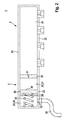
- the fuel distributor 2 distributes the fuel to a plurality of fuel injection valves 13, 14, 15, 16.
- the number of fuel injection valves 13 to 16 depends on the number of combustion chambers or cylinders of the internal combustion engine.
- the configuration of the fuel injection system 1 is hereinafter also with reference to the Fig. 2 further described.
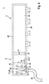
- Fig. 2 shows the fuel distributor 2 and the accumulator 3 of in Fig. 1 shown fuel injection system 1 of the first embodiment in an excerpt, schematic sectional view.
- a tubular body 20 is provided, in which both the fuel distributor 2 and the pressure accumulator 3 are configured.
- a stationary partition 21 is provided, which is fixedly connected to the tubular body 20.
- the partition wall 21 divides the tubular main body 20 into a distributor part 22 and an accumulator part 23.
- the fuel distributor 2 is formed in the distributor part 22 of the tubular main body 20, while the pressure accumulator 3 is formed in the pressure accumulator part 23 of the tubular main body 20.
- the pressure accumulator 3 also has a spring element 35, which is configured in this embodiment as a mechanical spring element.
- the spring element 35 extends through the annular stop element 29 and acts on the displaceable piston 26 with a spring force.
- the pressure of the fuel increases in the fuel distributor chamber 24, then this pressure acts on the end face 30 against the spring force of the spring element 35.
- the spring element 35 is further biased and the volume of the volume accumulator 27 increases.
- a volume compensation is made possible, which counteracts a pressure increase in the fuel distributor chamber 24.
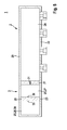
- Fig. 3 shows a diagram for explaining the operation of the fuel injection system 1 of the first embodiment.
- the time t is plotted on the abscissa, while at the ordinate the pressure (fuel pressure) p of the fuel 5 in the fuel distributor chamber 24 of the fuel distributor 2 is plotted.
- a working pressure p A is specified.
- a minimum pressure p M is specified.
- the minimum pressure p M can be predetermined, for example, by a start / stop application.
- the minimum pressure p M indicates the level at which an immediate Neither start can take place after a stop phase, without first requiring further pressure build-up. After the immediate restart of the internal combustion engine is then a pressure build up to the predetermined working pressure p A.
Abstract
Description
Die Erfindung betrifft eine Brennstoffeinspritzanlage, die insbesondere für gemischverdichtende, fremdgezündete Brennkraftmaschinen dient. Speziell betrifft die Erfindung das Gebiet der Brennstoffeinspritzanlagen für gemischverdichtende, fremdgezündete Brennkraftmaschinen von Kraftfahrzeugen.The invention relates to a fuel injection system, which is used in particular for Gemischverdichtende, spark-ignited internal combustion engines. Specifically, the invention relates to the field of fuel injection systems for mixture-compression, spark-ignited internal combustion engines of motor vehicles.
Aus der
Speziell bei einem Benzindirekteinspritzsystem für Brennkraftmaschinen wird der Brennstoff vom Tank bis in die Brennkammer der Brennkraftmaschine gefördert. Die Brennstoffeinspritzanlage besteht üblicherweise im Tank beginnend aus einem Niederdrucksystem, das sich aus einer Niederdruckpumpe, Brennstofffiltern und Leitungen zusammensetzt, gefolgt von einem Hochdrucksystem, das aus einer Hochdruckpumpe, einem Auslassventil, Brennstoffleitungen, einem Brennstoffverteiler und Injektoren zusammensetzt, welche den Brennstoff zeitlich und räumlich bedarfsgerecht der jeweiligen Brennkammer der Brennkraftmaschine zuführen. Gemischverdichtende, fremdgezündete Brennkraftmaschinen mit Benzindirekteinspritzung können aus Kosten- und Komplexitätsgründen auf eine Leckageleitung zum Niederdrucksystem verzichten. Dies bedeutet andererseits, dass der Brennstoffdruck nicht aktiv abgebaut wird.Especially in a gasoline direct injection system for internal combustion engines, the fuel is conveyed from the tank to the combustion chamber of the internal combustion engine. The fuel injection system usually consists in the tank starting from a low-pressure system, which consists of a low-pressure pump, fuel filters and lines, followed by a high-pressure system, which consists of a high-pressure pump, an exhaust valve, fuel lines, a fuel distributor and injectors, which the fuel in time and space needs feed the respective combustion chamber of the internal combustion engine. For reasons of cost and complexity, mixture-compression, spark-ignited internal combustion engines with gasoline direct injection can dispense with a leakage line to the low-pressure system. On the other hand, this means that the fuel pressure is not actively dissipated.
Dies hat den Nachteil, dass der Brennstoffdruck im Brennstoffverteiler beispielsweise im Schubbetrieb oder unmittelbar beim Abstellen der Brennkraftmaschine weiter ansteigen kann. Denn der frisch aus dem Tank geförderte Brennstoff wirkt im Brennstoffverteiler als Wärmesenke. Mit ansteigender Temperatur nimmt auch der Druck des Brennstoffs zu. Andererseits ergibt sich das Problem, dass bei längerer Standzeit die Temperatur im Hochdruckbereich und somit im Brennstoffverteiler abfällt. Dies wird durch eine mögliche Leckage und durch die nach dem Abstellen der Brennkraftmaschine sinkende Temperatur im Hochdruckbereich verursacht. Somit ergeben sich Probleme beim erneuten Starten, da zunächst der Systemdruck wieder aufgebaut werden muss.This has the disadvantage that the fuel pressure in the fuel distributor, for example, in overrun mode or immediately when switching off the internal combustion engine may continue to increase. Because the fuel freshly extracted from the tank acts as a heat sink in the fuel distributor. As the temperature increases, so does the pressure of the fuel. On the other hand, there is the problem that with a longer service life, the temperature drops in the high-pressure region and thus in the fuel distributor. This is caused by a possible leakage and by the decreasing after switching off the engine temperature in the high pressure area. Thus, problems arise when restarting, since first the system pressure must be rebuilt.
Die erfindungsgemäße Brennstoffeinspritzanlage mit den Merkmalen des Anspruchs 1 hat den Vorteil, dass ein Betriebsverhalten verbessert ist. Speziell ergibt sich der Vorteil, dass die Brennstoffeinspritzanlage für einen gewissen Zeitraum in einem betriebsbereiten Zustand gehalten werden kann.The fuel injection system according to the invention with the features of
Durch die in den Unteransprüchen aufgeführten Maßnahmen sind vorteilhafte Weiterbildungen der im Anspruch 1 angegebenen Brennstoffeinspritzanlage möglich.The measures listed in the dependent claims advantageous developments of the fuel injection system specified in
Bei der Ausgestaltung der Brennstoffeinspritzanlage kann ein Steuergerät insbesondere die Zeitsteuerung übernehmen. Das Steuergerät kann hierbei die Einspritzfunktionen und die Ansteuerung der Brennstoffeinspritzventile und anderer Steller zur Regelung der Brennstoffeinspritzanlage und der Brennkraftmaschine berechnen. Hierbei kann auch die Regelung des Systemdrucks im Hochdruckbereich durch das Steuergerät erfolgen, welches beispielsweise ein entsprechendes Mengensteuerventil ansteuert, so dass das zur Regelung benötigte Brennstoffvolumen verdichtet und in den Hochdruckbereich eingespritzt wird. Aus Kostengründen kann hierbei auf die Möglichkeit, den Brennstoff durch Ansteuerung eines Druckregel- oder Druckabbauventils aus dem Hochdruckbereich in den Niederdruckbereich oder in den Tank abführen zu können, verzichtet werden. Dadurch kann der Brennstoff aber nur noch als Leckage oder Einspritz- und gegebenenfalls Steuermenge über die Brennstoffeinspritzventile den Hochdruckbereich verlassen.In the embodiment of the fuel injection system, a control unit can in particular take over the timing. In this case, the control unit can calculate the injection functions and the control of the fuel injection valves and other actuators for controlling the fuel injection system and the internal combustion engine. In this case, the regulation of the system pressure in the high-pressure region can also be effected by the control device, which actuates, for example, a corresponding quantity control valve, so that the fuel volume required for regulation is compressed and injected into the high-pressure region. For cost reasons, it is possible here to dispense with the possibility of being able to discharge the fuel from the high-pressure region into the low-pressure region or into the tank by actuating a pressure-regulating or pressure-reducing valve. As a result, however, the fuel can only leave the high-pressure region as leakage or injection quantity and optionally control quantity via the fuel injection valves.
Bei einer Unterbrechung der Einspritzung, beispielsweise bei einem Schubbetrieb oder bei einem Abstellen der Brennkraftmaschine, bleibt somit der Systemdruck auf dem direkt vor dem Abschalten der Einspritzungen erreichten Niveau. Der im Hochdruckbereich verbleibende Brennstoff erwärmt sich zunächst, da er als Wärmesenke dient. In vorteilhafter Weise wird das bei der Erwärmung des Brennstoffs zusätzlich benötigte Volumen von dem Druckspeicher zur Verfügung gestellt. Der Druckspeicher kann somit die temperaturbedingte Volumenvergrößerung des Brennstoffs ausgleichen. Somit wird ein Druckanstieg vermieden. Hierdurch kann auch ein Öffnen eines Druckbegrenzungsventils, das den Druck des Hochdruckbereichs zum Schutz der Hochdruckkomponenten begrenzt, vermieden werden.In an interruption of the injection, for example, during a coasting operation or when switching off the internal combustion engine, thus the system pressure remains at the level reached directly before switching off the injections. The remaining fuel in the high-pressure area heats up first, since it serves as a heat sink. Advantageously, the additionally required volume in the heating of the fuel of the Pressure accumulator provided. The accumulator can thus compensate for the temperature-induced increase in volume of the fuel. Thus, a pressure increase is avoided. As a result, it is also possible to avoid opening a pressure-limiting valve which limits the pressure of the high-pressure region in order to protect the high-pressure components.
Wenn die Hochdruckpumpe für einen längeren Zeitraum nicht angetrieben wird, dann sinkt die Temperatur im Hochdruckbereich und somit insbesondere im Brennstoffverteiler. Die temperaturbedingte Dichtezunahme des Brennstoffs und eine mögliche Leckage haben dann eine drucksenkende Wirkung. Speziell bei Start/Stopp-Anwendungen oder im elektrischen Fahrbetrieb bei Hybridfahrzeugen kann es zu Stopp- und Abkühlphasen kommen, die mehrere Minuten lang sind. Der hierdurch bedingte Druckabfall im Hochdruckbereich kann für sich genommen so groß sein, dass der Brennstoffdruck ein Niveau unterschreitet, bei dem eine für den Wiederstart geeignete Einspritzung noch erfolgen kann. In vorteilhafter Weise kann durch den Druckspeicher der Zeitraum bis zum Unterschreiten dieses Niveaus verlängert werden. Somit kann der Fall, dass die Hochdruckpumpe zunächst den Systemdruck für eine Brennstoffeinspritzung aufbauen kann, was die Startzeit deutlich verlängert, vermieden werden.If the high-pressure pump is not driven for a long period, then the temperature drops in the high-pressure region and thus in particular in the fuel distributor. The temperature-related increase in density of the fuel and a possible leakage then have a pressure-reducing effect. Especially in start / stop applications or in electric driving in hybrid vehicles, it can come to stop and cool down phases that are several minutes long. The resulting pressure drop in the high-pressure region can in itself be so great that the fuel pressure falls below a level at which a suitable for restarting injection can still take place. Advantageously, can be extended by the pressure accumulator, the period to below this level. Thus, the case that the high-pressure pump can first build up the system pressure for fuel injection, which significantly prolongs the start time, can be avoided.
Ferner ist es denkbar, dass die Leckagewerte an den Ventilen der Hochdruckpumpe im Rahmen der Fertigungstoleranzen streuen. Über die Ausbringungsmenge ergeben sich somit besonders dichte Exemplare, aber auch weniger dichte. Im Rahmen der fertigungstechnischen Streuung ergibt sich somit das Problem, das bei einer hohen Leckage auch ein früher Wiederstart nach einer Start/Stopp-Phase erforderlich ist oder dass sogar unmittelbar nach dem Anhalten der Brennkraftmaschine ein Wiederstart erforderlich ist, um eine durch den gesunkenen Druck bedingte lange Wiederstartzeit zu vermeiden. Durch den Druckspeicher kann auch in diesen Fällen über einen längeren Zeitraum ein ausreichend hoher Systemdruck gewährleistet werden. Hierdurch können im Rahmen der Fertigung und Sortierung der Hochdruckpumpen auch größere Leckagewerte zugelassen werden. Dies verbessert die Grundlage von Start/Stopp- und Hybridanwendungen.Furthermore, it is conceivable that the leakage values at the valves of the high-pressure pump scatter within the scope of the manufacturing tolerances. About the output amount thus result particularly dense specimens, but also less dense. In the context of manufacturing dispersion, there is thus the problem that, in the event of a high leakage, an early restart after a start / stop phase is required or even a restart is required immediately after stopping the internal combustion engine in order to reduce the pressure caused by the reduced pressure long restart time to avoid. Due to the accumulator, a sufficiently high system pressure can be ensured even in these cases over a longer period. As a result, larger leakage values can be permitted within the scope of production and sorting of the high-pressure pumps. This improves the foundation of start / stop and hybrid applications.
Somit kann in vorteilhafter Weise sichergestellt werden, dass der Druck im Hochdrucksystem beispielsweise auch nach einem Motorabstellen ohne eine Steuergeräteaktivität über einen längeren Zeitraum nicht unter das Niveau fällt, das für einen Wiederstart erforderlich ist und unter dem nur ein verzögerter Wiederstart möglich ist. Ein Druck, der deutlich über dem Niederdruck einer Niederdruckpumpe (Vorförderpumpe) liegt, ist insbesondere für Direktstart-Anwendungen und Anlasser unterstützte Direktstart-Anwendungen erforderlich.Thus, it can be ensured in an advantageous manner that the pressure in the high-pressure system, for example, even after an engine shutdown without a controller activity over a longer period does not fall below the level required for a restart and under which only a delayed restart is possible. A pressure that is well above the low pressure of a low-pressure pump (prefeed pump) In particular, direct start applications supported by direct start applications and starters are required.
Vorteilhaft ist es, dass der Druckspeicher einen Volumenspeicher mit einem variablen Volumen aufweist und dass der Volumenspeicher des Druckspeichers mit dem Brennstoffverteilerraum verbunden ist. Der Druckspeicher kann somit als Energie- und Volumenspeicher dienen. Der Druckspeicher beziehungsweise der Volumenspeicher des Druckspeichers ist in vorteilhafter Weise über eine gedrosselte Verbindung mit dem Brennstoffverteilerraum verbunden. Hierdurch kann eine Volumenänderung, insbesondere eine temperaturbedingte Volumenänderung, des Brennstoffs im Brennstoffverteilerraum durch Brennstoff aus dem Volumenspeicher ausgeglichen werden, wobei sich das Volumen des Volumenspeichers ändert. Hierdurch kann auch eine mögliche Leckage im System ausgeglichen werden. Dies ermöglicht nach dem Abstellen des Motors in Abhängigkeit von den Rahmenbedingungen des Abstellens den Druck im Hochdruckbereich der Brennstoffeinspritzanlage, also insbesondere im Brennstoffverteiler, über einen längeren Zeitraum über dem gewünschten Niveau zu halten. Die gedrosselte Verbindung kann hierbei über eine Drosselbohrung oder über eine anders ausgestaltete Drossel realisiert sein. Wird die Brennkraftmaschine somit beispielsweise bei einer Start/Stopp-Anwendung im Betrieb abgestellt, wodurch sich in Folge von Leckage und/oder Temperaturabnahme das Brennstoffvolumen im Brennstoffverteilerraum verringert, so wird aus dem Volumenspeicher Brennstoff bei entsprechendem Druck nachgefördert und somit wird der Brennstoffdruck im Brennstoffverteiler über einen längeren Zeitraum aufrechterhalten.It is advantageous that the pressure accumulator has a volume accumulator with a variable volume and that the volume accumulator of the pressure accumulator is connected to the fuel distributor chamber. The accumulator can thus serve as energy and volume storage. The pressure accumulator or the volume accumulator of the pressure accumulator is connected in an advantageous manner via a throttled connection with the fuel distributor chamber. In this way, a volume change, in particular a temperature-induced change in volume, of the fuel in the fuel distributor space can be compensated by fuel from the volume accumulator, the volume of the volume accumulator changing. As a result, a possible leakage in the system can be compensated. This allows after stopping the engine as a function of the conditions of shutdown to maintain the pressure in the high pressure region of the fuel injection system, ie in particular in the fuel distributor, over a longer period above the desired level. The throttled connection can in this case be realized via a throttle bore or via a differently configured throttle. If the internal combustion engine is thus turned off during operation, for example during a start / stop application, whereby the fuel volume in the fuel distributor chamber is reduced as a result of leakage and / or temperature decrease, then fuel is fed from the volume reservoir at the corresponding pressure and thus the fuel pressure in the fuel distributor changes maintain a longer period of time.
Ferner ist es vorteilhaft, dass der Druckspeicher einen verschiebbaren Kolben aufweist, der das Volumen des Volumenspeichers des Druckspeichers begrenzt. Hierbei kann außerdem in vorteilhafter Weise zumindest ein Federelement vorgesehen sein, das den verschiebbaren Kolben mit einer Federkraft beaufschlagt. Wenn die Hochdruckpumpe im Betrieb unter hohem Druck stehenden Brennstoff in den Brennstoffverteilerraum fördert, dann wird das Federelement vorgespannt. Zusätzlich kann das Federelement gegebenenfalls auch noch etwas weiter gespannt werden, wenn der Brennstoff beispielsweise unmittelbar nach dem Abstellen der Brennkraftmaschine als Wärmesenke wirkt und sich somit zunächst noch etwas ausdehnt. Hierdurch kann ein unerwünschter Druckanstieg im Brennstoffverteilerraum, der gegebenenfalls das Öffnen eines Druckbegrenzungsventils erforderlich machen würde, vermieden werden.Furthermore, it is advantageous that the pressure accumulator has a displaceable piston which limits the volume of the volume accumulator of the pressure accumulator. In this case, at least one spring element can also be provided in an advantageous manner, which acts on the displaceable piston with a spring force. When the high pressure pump delivers high pressure fuel into the fuel rail during operation, the spring is biased. In addition, if necessary, the spring element can also be stretched slightly further if, for example, the fuel acts as a heat sink immediately after switching off the internal combustion engine and thus initially expands somewhat. As a result, an undesirable increase in pressure in the fuel distributor chamber, which would possibly necessitate the opening of a pressure limiting valve, can be avoided.
In vorteilhafter Weise kann das Federelement als mechanisches Federelement oder als Gasfeder ausgestaltet sein. Wenn das Federelement als mechanisches Federelement ausgestaltet ist, dann kann der Teilraum, in dem das Federelement angeordnet ist, druckentlastet sein. In diesem Fall ist vorzugsweise eine Brennstoffrückführung vorgesehen, um einen Leckagerückfluss zu ermöglichen. Wenn das Federelement hingegen als Gasfeder ausgestaltet ist, dann herrscht beidseitig des Kolbens der gleiche Druck, so dass auf solch eine Leckagerückführung auch verzichtet werden kann. Ferner ist auch eine kombinierte Ausgestaltung mit einem Federelement und einer Gasfeder denkbar.Advantageously, the spring element can be designed as a mechanical spring element or as a gas spring. If the spring element is designed as a mechanical spring element, then the subspace in which the spring element is arranged, be depressurized. In this case, a fuel return is preferably provided to allow leakage backflow. If, however, the spring element is configured as a gas spring, then the same pressure prevails on both sides of the piston, so that such a leakage return can also be dispensed with. Furthermore, a combined embodiment with a spring element and a gas spring is conceivable.
Außerdem ist es vorteilhaft, dass eine Verschiebung des Kolbens derart begrenzt ist, dass ein maximales Volumen des Volumenspeichers des Druckspeichers vorgegeben ist. In Bezug auf eine Vorspannung des Federelements kann hierdurch die maximale Vorspannkraft und somit die maximale Federkraft begrenzt werden. Dies begrenzt andererseits auch den maximalen Brennstoffdruck im Brennstoffverteilerraum.Moreover, it is advantageous that a displacement of the piston is limited such that a maximum volume of the volume accumulator of the pressure accumulator is predetermined. With respect to a bias of the spring element can thereby be limited to the maximum biasing force and thus the maximum spring force. On the other hand, this also limits the maximum fuel pressure in the fuel distributor space.
Außerdem ist es hierbei vorteilhaft, dass ein Anschlag für den Kolben vorgegeben ist, der die Verschiebung des Kolbens begrenzt. Zusätzlich oder alternativ ist es auch vorteilhaft, dass ein Absteuerkanal vorgesehen ist und dass eine Kante des Kolbens den Absteuerkanal derart ansteuert, dass bei dem maximalen Volumen des Volumenspeichers des Druckspeichers eine Verbindung zwischen dem Volumenspeicher und dem Absteuerkanal geöffnet ist. Durch den Absteuerkanal kann beim Erreichen des maximalen Volumens des Volumenspeichers eine weitere temperaturbedingte Volumenzunahme des Brennstoffs im Brennstoffverteilerraum durch Absteuern einer Brennstoffmenge ausgeglichen werden. Dadurch wird eine weitere Zunahme des Brennstoffdrucks im Brennstoffverteilerraum verhindert. Durch den Anschlag für den Kolben kann eine Vorspannung des Federelements begrenzt werden. Hierbei ist es auch möglich, dass anstelle eines Absteuerkanals eine Druckbegrenzung über ein Druckbegrenzungsventil erfolgt, wenn der Kolben den Anschlag erreicht.In addition, it is advantageous in this case that a stop for the piston is predetermined, which limits the displacement of the piston. Additionally or alternatively, it is also advantageous that a Absteuerkanal is provided and that an edge of the piston controls the Absteuerkanal such that at the maximum volume of the volume accumulator of the pressure accumulator, a connection between the volume accumulator and the Absteuerkanal is open. When the maximum volume of the volume accumulator is reached, a further temperature-related volume increase of the fuel in the fuel distributor chamber can be compensated for by the diversion channel by controlling a quantity of fuel. This prevents a further increase in fuel pressure in the fuel rail. By the stop for the piston, a bias of the spring element can be limited. It is also possible that instead of a Absteuerkanals a pressure relief via a pressure relief valve, when the piston reaches the stop.
Vorteilhaft ist es auch, dass ein rohrförmiger Grundkörper vorgesehen ist, dass der Brennstoffverteiler in einem Verteilerteil des rohrförmigen Grundkörpers ausgebildet ist und dass der Druckspeicher in einem Druckspeicherteil des rohrförmigen Grundkörpers ausgebildet ist. Dies stellt eine Möglichkeit dar, um den Brennstoffverteiler und den Druckspeicher innerhalb eines gemeinsamen Grundkörpers auszugestalten. Hierdurch vereinfacht sich zum einen die Herstellung und zum anderen ergibt sich eine kompakte Ausgestaltung der Brennstoffeinspritzanlage und eine damit verbundene vereinfachte Montage.It is also advantageous that a tubular base body is provided, that the fuel distributor is formed in a distributor part of the tubular base body and that the pressure accumulator is formed in an accumulator part of the tubular base body. This represents a possibility to design the fuel distributor and the accumulator within a common body. This simplifies on the one hand the production and on the other hand results in a compact design of the fuel injection system and associated simplified assembly.
Bevorzugte Ausführungsbeispiele der Erfindung sind in der nachfolgenden Beschreibung unter Bezugnahme auf die beigefügten Zeichnungen, in denen sich entsprechende Elemente mit übereinstimmenden Bezugszeichen versehen sind, näher erläutert. Es zeigt:
-
Fig. 1 eine Brennstoffeinspritzanlage entsprechend einem ersten Ausführungsbeispiel der Erfindung in einer schematischen Darstellung; -
Fig. 2 einen Brennstoffverteiler und einen Druckspeicher der inFig. 1 dargestellten Brennstoffeinspritzanlage entsprechend dem ersten Ausführungsbeispiel in einer auszugsweisen, schematischen Schnittdarstellung; -
Fig. 3 ein Diagramm zur Erläuterung der Funktionsweise der inFig. 1 dargestellten Brennstoffeinspritzanlage entsprechend dem ersten Ausführungsbeispiel der Erfindung; -
Fig. 4 den Brennstoffverteiler und den Druckspeicher, die inFig. 2 dargestellt sind, entsprechend einem zweiten Ausführungsbeispiel der Erfindung; -
Fig. 5 den Brennstoffverteiler und den Druckspeicher, die inFig. 2 dargestellt sind, entsprechend einem dritten Ausführungsbeispiel der Erfindung und -
Fig. 6 den Brennstoffverteiler und den Druckspeicher, die inFig. 2 dargestellt sind, entsprechend einem vierten Ausführungsbeispiel der Erfindung.
-
Fig. 1 a fuel injection system according to a first embodiment of the invention in a schematic representation; -
Fig. 2 a fuel distributor and an accumulator of inFig. 1 illustrated fuel injection system according to the first embodiment in a partial, schematic sectional view; -
Fig. 3 a diagram explaining the operation of inFig. 1 illustrated fuel injection system according to the first embodiment of the invention; -
Fig. 4 the fuel distributor and the pressure accumulator, which inFig. 2 are shown, according to a second embodiment of the invention; -
Fig. 5 the fuel distributor and the pressure accumulator, which inFig. 2 are shown, according to a third embodiment of the invention and -
Fig. 6 the fuel distributor and the pressure accumulator, which inFig. 2 are shown, according to a fourth embodiment of the invention.
Die Brennstoffeinspritzanlage 1 weist einen Brennstoffverteiler 2 und einen Druckspeicher 3 auf. Ferner weist die Brennstoffanlage 1 einen Tank 4 auf, der zum Bevorraten des Brennstoffs 5 dient. Über eine Niederdruckpumpe (Vorförderpumpe) 6 wird der Brennstoff 5 zu einer Hochdruckpumpe 7 gefördert. Die Niederdruckpumpe 6 ist hierfür über eine Leitung 8 mit der Hochdruckpumpe 7 verbunden. Ferner ist eine Ausgangsseite der Hochdruckpumpe 7 über eine Leitung 9 mit dem Brennstoffverteiler 2 verbunden. In der Leitung 9 ist hierbei ein Auslassventil 10 angeordnet, das als Rückschlagventil 10 ausgestaltet ist, das Auslassventil 10 verhindert ein Rückfließen von Brennstoff aus dem Brennstoffverteiler 2 in die Hochdruckpumpe 7. Ferner ist ein Mengensteuerventil 11 vorgesehen, das von einem nicht dargestellten Steuergerät zur Regelung des Brennstoffdrucks im Brennstoffverteiler 2 so angesteuert wird, dass das zur Regelung benötigte Brennstoffvolumen verdichtet und in den Hochdruckbereich eingespeist wird. Ferner ist ein Druckbegrenzungsventil 12 vorgesehen, das zum Schutz der Hochdruckkomponenten den Brennstoffdruck im Brennstoffverteiler 2 begrenzt.The
Der Brennstoffverteiler 2 verteilt den Brennstoff auf mehrere Brennstoffeinspritzventile 13, 14, 15, 16. Die Anzahl der Brennstoffeinspritzventile 13 bis 16 hängt hierbei von der Anzahl der Brennräume beziehungsweise Zylinder der Brennkraftmaschine ab.The
Die Ausgestaltung der Brennstoffeinspritzanlage 1 ist im Folgenden auch unter Bezugnahme auf die
Der Raum 25 des Druckspeichers 3 ist allerdings durch einen Kolben 26 in einen Volumenspeicher 27 und einen Federraum 28 unterteilt. Der Kolben 26 ist hierbei innerhalb des rohrförmigen Grundkörpers 20 verschiebbar. In diesem Ausführungsbeispiel ist der Kolben 26 zwischen der Trennwand 21 und einem ringförmigen Anschlagelement 29, das fest mit dem rohrförmigen Grundkörper 20 verbunden ist, verschiebbar. Die Trennwand 21 und das ringförmige Anschlagelement 29 bilden somit mechanische Anschläge 21, 29 für den Kolben 26, wodurch ein Verstellweg des Kolbens 26 begrenzt ist. Der verschiebbare Kolben 26 des Druckspeichers 3 begrenzt mit seiner Stirnseite 30 das Volumen des Volumenspeichers 27 des Druckspeichers 3. Da sich das Volumen des Volumenspeichers 27 mit der momentanen Stellung des Kolbens 26 ändert, weist der Volumenspeicher 27 ein variables Volumen auf. Der Volumenspeicher 27 des Druckspeichers 3 ist über eine gedrosselte Verbindung 31, die in diesem Ausführungsbeispiel als Drosselbohrung 31 ausgestaltet ist, mit dem Brennstoffverteilerraum 24 verbunden.However, the space 25 of the
Der Druckspeicher 3 weist außerdem ein Federelement 35 auf, das in diesem Ausführungsbeispiel als mechanisches Federelement ausgestaltet ist. Das Federelement 35 erstreckt sich durch das ringförmige Anschlagelement 29 und beaufschlagt den verschiebbaren Kolben 26 mit einer Federkraft. Steigt im Betrieb der Druck des Brennstoffs im Brennstoffverteilerraum 24 an, dann wirkt dieser Druck auf die Stirnseite 30 entgegen der Federkraft des Federelements 35. Dadurch wird das Federelement 35 weiter vorgespannt und das Volumen des Volumenspeichers 27 nimmt zu. Somit wird ein Volumenausgleich ermöglicht, der einem Druckanstieg im Brennstoffverteilerraum 24 entgegen wirkt. Nimmt andererseits der Druck des Brennstoffs im Brennstoffverteilerraum 24 ab, dann wird auf Grund der Federkraft des Federelements 35, die über die Stirnseite 30 einen Druck im Volumenspeicher 27 aufrechterhält, Brennstoff über die gedrosselte Verbindung 31 in den Brennstoffverteilerraum 24 nachgeführt. Hierbei nimmt das Volumen des Volumenspeichers 27 ab.The
Der Raum 25 des Druckspeichers 3 ist gegenüber dem Volumenspeicher 27 in der Anschlagposition am Anschlagelement 29 druckbeaufschlagt. Somit kommt es auf Grund von Leckage an dem verschiebbaren Kolben 26 zur Ansammlung von Brennstoff in dem Raum 25. Dieser Brennstoff wird jedoch über eine Rückführleitung 36 abgeführt. Je nach Ausgestaltung kann die Rückführleitung 36 beispielsweise in den Tank 4 führen.The space 25 of the
Die Funktionsweise der Brennstoffeinspritzanlage 1 des ersten Ausführungsbeispiels ist im Folgenden auch anhand der
Zu Beginn herrscht im Brennstoffverteiler 2 der Arbeitsdruck pA, wie es durch den Abschnitt 40 gezeigt ist. Zum Zeitpunkt t0 erfolgt durch das Steuergerät eine Stopp-Anforderung, bei der die Brennkraftmaschine abgestellt wird. Der Kurvenverlauf 41 veranschaulicht den Druckverlauf 41 bei einem herkömmlichen System ohne Druckspeicher 3. Gleich nach dem Zeitpunkt t0 fällt der Druck t entsprechend dem Druckverlauf 41 ab, so dass bereits zum Zeitpunkt t1 der Mindestdruck pM unterschritten wird. Ein unmittelbarer Wiederstart ist somit nur zwischen dem Zeitpunkt t0 und dem Zeitpunkt t1 möglich.Initially, in the
Der Druckverlauf 41 kommt durch eine Temperaturabnahme und damit verbundene Dichtezunahme sowie durch eine Gesamtleckage zusammen. Beides führt zu einer Volumenabnahme, was eine Druckabsenkung bedingt. Eine zunächst mögliche Drucksteigerung über den Arbeitsdruck pA ist hierbei nicht dargestellt. Bei sehr dichten Systemen kann jedoch infolge eines Wärmeeintrags in den Brennstoff der Druck zunächst auch ansteigen.The
Nach dem Zeitpunkt t1 kann ein Wiederstart der Brennkraftmaschine eines herkömmlichen Systems somit verzögert sein, da zunächst der Druckaufbau erfolgen muss. Möglich ist auch eine Ausgestaltung, bei der der Druck p fortlaufend erfasst wird und bereits beim Unterschreiten des Mindestdrucks pM eine Start-Anforderung im Rahmen der Start/Stopp-Anwendung erfolgt. Dies ermöglicht zwar stets einen unmittelbaren Wiederstart, macht jedoch bei einer längeren Stopp-Phase bereits zum Zeitpunkt t1 einen Wiederstart erforderlich, selbst wenn das Fahrzeug weiterhin steht. Somit kommt es zu einer durchschnittlich verringerten Brennstoffeinsparung durch die Start/Stopp-Anwendung. Wegen bestehender Fertigungstoleranzen kann in einem ungünstigen Fall der Zeitpunkt t1 auch so nahe an dem Zeitpunkt t0 liegen, dass beim Benutzer (Fahrer) der Eindruck entsteht, dass die Start/Stopp-Anwendung nicht in der gewünschten Weise arbeitet oder fehlerhaft ist.After time t 1 , a restart of the internal combustion engine of a conventional system can thus be delayed, since first the pressure build-up must take place. Also possible is an embodiment in which the pressure p is detected continuously and already when falling below the minimum pressure p M is a start request in the context of the start / stop application. Although this always allows an immediate restart, but makes at a longer stop phase at time t 1, a restart required even if the vehicle is still. Thus, there is an average reduced fuel savings through the start / stop application. Due to existing manufacturing tolerances in an unfavorable case, the time t 1 Also so close to the time t 0 are that the user (driver) gives the impression that the start / stop application is not working in the desired manner or is faulty.
Bei der Ausgestaltung der Brennstoffeinspritzaniage 1 entsprechend dem ersten Ausführungsbeispiel ergibt sich der Kurvenverlauf (Druckverlauf) 42. Hierbei kommt es bis zum Zeitpunkt t2 zu einem Druck p im Brennstoffverteiler 2, der zumindest näherungsweise gleich dem Arbeitsdruck pA ist. Erst wenn das Volumen des Volumenspeichers 27 aufgebraucht ist, da der Kolben 26 an der Trennwand 21 anschlägt, kommt es ab dem Zeitpunkt t2 zu einem stärkeren Druckabfall. Hierbei kann je nach Größe des Volumenspeichers 27 der Zeitpunkt t2 sogar hinter dem Zeitpunkt t1 liegen. Jedenfalls liegt der Zeitpunkt t3 nach dem Zeitpunkt t1, da es nicht zum Zeitpunkt t0, sondern erst zum späteren Zeitpunkt t2 zu einem verstärkten Druckabfall kommt. Somit bleibt der Druck p des Brennstoffs im Brennstoffverteiler 2 für einen längeren Zeitraum, nämlich vom Zeitpunkt t0 bis zum Zeitpunkt t3, über dem Mindestdruck tM.In the embodiment of the
Daher kann beispielsweise die Funktionsweise einer Start/Stopp-Anwendung unterstützt und somit erheblich verbessert werden.Therefore, for example, the operation of a start / stop application can be supported and thus significantly improved.
Außerdem können Effekte, bei denen nach dem Zeitpunkt t0 der Druck p zunächst über den Arbeitsdruck tA ansteigt, ausgeglichen werden. Denn der Druckspeicher 3, insbesondere das Federelement 35, kann so ausgelegt werden, dass beim Arbeitsdruck pA der Kolben 26 noch nicht in der Anschlagsposition an dem ringförmigen Anschlagelement 29 angeordnet ist. Somit kann der Volumenspeicher 27 noch ein zusätzliches Volumen aufnehmen, um einen Druckanstieg über den Arbeitsdruck pA auszugleichen. Beispielsweise kann sich der Kolben 26 in der in der
Außerdem kann zur Verbesserung eines Kaltstarts das Federelement 35 bereits auf ein bestimmtes Niveau vorgespannt werden, um zu verhindern, dass beim ersten Start das Volumen des Volumenspeichers 27 ebenfalls auf ein ausreichendes Druckniveau gebracht werden muss, welches für den Kaltstart erforderlich ist. Somit wird die Startzeit für den Kaltstart nicht beeinträchtigt. Bei dieser Ausgestaltung befindet sich der Kolben 26 dann vor dem Kaltstart an der Trennwand 21, wobei die Federkraft des Federelements 35 so groß ist, dass erst über einem Druckniveau für den Kaltstart eine Betätigung des Kolbens 26 und somit eine Befüllung des Volumenspeichers 27 erfolgt.In addition, to improve a cold start, the
Durch die Festlegung des mechanischen Anschlags 29 kann darüber hinaus die gespeicherte Federenergie begrenzt werden. Bei sehr dichten Systemen kann somit ein übermäßiger Druckanstieg unmittelbar nach dem Zeitpunkt t0 durch Öffnen des Druckbegrenzungsventils 12 verhindert werden.By fixing the mechanical stop 29 beyond the stored spring energy can be limited. In the case of very dense systems, an excessive increase in pressure can thus be prevented immediately after the time t 0 by opening the
In der in der
Durch die Ansteuerung des Absteuerkanals 50 ist außerdem eine Druckbegrenzung gewährleistet. Denn wenn der Druck p im Brennstoffverteilerraum 24 und somit auch im Volumenspeicher 27 über einen vorgegebenen Wert ansteigt, dann kommt es über die Stirnseite 30 des Kolbens 26 zu einer so großen Beaufschlagung des Federelements 35, dass der Absteuerkanal 50 mit dem Volumenspeicher 27 verbunden wird. Somit kann über die Federkonstante des Federelements 35 und den diesbezüglichen Verstellweg die gewünschte Druckbegrenzung eingestellt werden.By controlling the
Je nach Ausgestaltung der Brennstoffeinspritzanlage 1 kann bei diesem Ausführungsbeispiel das Druckbegrenzungsventil 12 gegebenenfalls auch entfallen.Depending on the configuration of the
Da die Drücke im Volumenspeicher 27 und im Federraum 28 zumindest näherungsweise gleich groß sind, kann eine ausreichende Dichtwirkung durch den Kolben 26, die insbesondere ein Eindringen von Brennstoff in den Federraum 28 verhindert, verhältnismäßig einfach realisiert werden. Somit tritt auch keine Leckage auf.Since the pressures in the volume memory 27 and the spring chamber 28 are at least approximately the same size, a sufficient sealing effect by the
Die Gasfeder 54 ermöglicht somit eine ähnliche Funktionsweise wie das mechanische Federelement 35, wie es anhand der
Die Erfindung ist nicht auf die beschriebenen Ausführungsbeispiele beschränkt.
The invention is not limited to the described embodiments.
Claims (10)
dadurch gekennzeichnet,
dass ein Druckspeicher (3) vorgesehen ist, der mit dem Brennstoffverteilerraum (24) verbunden ist.Fuel injection system (1), in particular for mixture-compression, spark-ignited internal combustion engines, having a fuel distributor (2), which has a fuel distributor chamber (24),
characterized,
in that an accumulator (3) is provided which is connected to the fuel distributor chamber (24).
dadurch gekennzeichnet,
dass der Druckspeicher (3) einen Volumenspeicher (27) mit einem variablen Volumen aufweist und dass der Volumenspeicher (27) des Druckspeichers (3) mit dem Brennstoffverteilerraum (24) verbunden ist.Fuel injection system according to claim 1,
characterized,
that the pressure accumulator (3) comprises a volume memory (27) having a variable volume and that the volume accumulator (27) of the accumulator (3) with the fuel distribution chamber (24) is connected.
dadurch gekennzeichnet,
dass der Druckspeicher (3) beziehungsweise der Volumenspeicher (27) des Druckspeichers (3) über eine gedrosselte Verbindung (31) mit dem Brennstoffverteilerraum (24) verbunden ist.Fuel injection system according to claim 1 or 2,
characterized,
that the pressure accumulator (3) and the volume of memory (27) of the accumulator (3) via a throttled connection (31) with the fuel distribution chamber (24) is connected.
dadurch gekennzeichnet,
dass der Druckspeicher (3) einen verschiebbaren Kolben (26) aufweist, der das Volumen des Volumenspeichers (27) des Druckspeichers (3) begrenzt.Fuel injection system according to claim 2 or 3,
characterized,
in that the pressure accumulator (3) has a displaceable piston (26) which limits the volume of the volume accumulator (27) of the pressure accumulator (3).
dadurch gekennzeichnet,
dass zumindest ein Federelement (35, 54) vorgesehen ist, das den verschiebbaren Kolben (26) mit einer Federkraft beaufschlagt.Fuel injection system according to claim 4,
characterized,
in that at least one spring element (35, 54) is provided, which acts on the displaceable piston (26) with a spring force.
dadurch gekennzeichnet,
dass das Federelement (35, 54) als mechanisches Federelement (35) oder als Gasfeder (54) ausgestaltet ist.Fuel injection system according to claim 5,
characterized,
that the spring element (35, 54) as a mechanical spring element (35) or as a gas spring (54) is arranged.
dadurch gekennzeichnet,
dass ein Anschlag (29) für den Kolben (26) vorgegeben ist, der die Verschiebung des Kolbens (26) begrenzt, und/oder dass ein Absteuerkanal (50) vorgesehen ist und dass eine Kante (53) des Kolbens (26) den Absteuerkanal (50) derart ansteuert, dass bei dem maximalen Volumen des Volumenspeichers (27) des Druckspeichers (3) eine Verbindung zwischen dem Volumenspeicher (27) und dem Absteuerkanal (50) geöffnet ist.Fuel injection system according to claim 7,
characterized,
in that a stop (29) for the piston (26) is provided, which limits the displacement of the piston (26), and / or that a discharge channel (50) is provided, and that an edge (53) of the piston (26) forms the discharge channel (50) controls such that at the maximum volume of the volume memory (27) of the pressure accumulator (3), a connection between the volume memory (27) and the Absteuerkanal (50) is opened.
dadurch gekennzeichnet,
dass eine elastisch verformbare Membran (60) vorgesehen ist, die das Volumen des Volumenspeichers (27) begrenzt.Fuel injection system according to one of claims 1 to 8,
characterized,
in that an elastically deformable membrane (60) is provided which limits the volume of the volume accumulator (27).
dadurch gekennzeichnet,
dass ein rohrförmiger Grundkörper (20) vorgesehen ist, dass der Brennstoffverteiler (2) in einem Verteilerteil (22) des rohrförmigen Grundkörpers (22) ausgebildet ist und dass der Druckspeicher (3) in einem Druckspeicherteil (23) des rohrförmigen Grundkörpers (22) ausgebildet ist.Fuel injection system according to one of claims 1 to 9,
characterized,
in that a tubular basic body (20) is provided, in that the fuel distributor (2) is formed in a distributor part (22) of the tubular basic body (22) and in that the pressure accumulator (3) is formed in a pressure storage part (23) of the tubular basic body (22) is.
Priority Applications (1)
| Application Number | Priority Date | Filing Date | Title |
|---|---|---|---|
| PL13165098T PL2674609T3 (en) | 2012-06-12 | 2013-04-24 | Fuel injection system |
Applications Claiming Priority (1)
| Application Number | Priority Date | Filing Date | Title |
|---|---|---|---|
| DE102012209747A DE102012209747A1 (en) | 2012-06-12 | 2012-06-12 | fuel injection system |
Publications (2)
| Publication Number | Publication Date |
|---|---|
| EP2674609A1 true EP2674609A1 (en) | 2013-12-18 |
| EP2674609B1 EP2674609B1 (en) | 2016-02-24 |
Family
ID=48182782
Family Applications (1)
| Application Number | Title | Priority Date | Filing Date |
|---|---|---|---|
| EP13165098.8A Not-in-force EP2674609B1 (en) | 2012-06-12 | 2013-04-24 | Fuel injection system |
Country Status (4)
| Country | Link |
|---|---|
| EP (1) | EP2674609B1 (en) |
| DE (1) | DE102012209747A1 (en) |
| ES (1) | ES2566906T3 (en) |
| PL (1) | PL2674609T3 (en) |
Cited By (2)
| Publication number | Priority date | Publication date | Assignee | Title |
|---|---|---|---|---|
| CN106499557A (en) * | 2016-10-17 | 2017-03-15 | 江苏大学 | A kind of high pressure oil rail with feeding pressure stabilizing device |
| CN111636942A (en) * | 2020-04-29 | 2020-09-08 | 潍坊职业学院 | Hydraulic drive variable valve timing mechanism |
Families Citing this family (2)
| Publication number | Priority date | Publication date | Assignee | Title |
|---|---|---|---|---|
| GB2547711B (en) * | 2016-02-29 | 2020-01-29 | Delphi Tech Ip Ltd | Common rail with variable inner volume reservoir |
| RU2737571C1 (en) * | 2020-08-11 | 2020-12-01 | Евгений Викторович Горбачевский | Fuel accumulator and method to control wave phenomena in high pressure line of accumulator fuel system of internal combustion engines |
Citations (7)
| Publication number | Priority date | Publication date | Assignee | Title |
|---|---|---|---|---|
| DE19720731A1 (en) * | 1996-05-20 | 1997-11-27 | Denso Corp | Fuel injector with vibration damper for directly injected petrol engine |
| EP1197649A1 (en) * | 2000-10-12 | 2002-04-17 | Toyota Jidosha Kabushiki Kaisha | High-pressure fuel supply system and method |
| DE102005053470A1 (en) * | 2004-11-29 | 2006-06-01 | Renault S.A.S. | Common rail for use in fuel supply system, has closing unit shifted to connect one of chamber to other chamber if fuel pressure inside latter chamber is larger than threshold value of fuel pressure |
| FR2889260A3 (en) * | 2005-07-26 | 2007-02-02 | Renault Sas | Common fuelling rail for diesel engine of motor vehicle, has wall with conduit in fluid communication with chambers and modifying volume of one chamber under effect of fuel pressure in chamber, where chambers receive fuel under pressure |
| FR2889259A3 (en) * | 2005-07-26 | 2007-02-02 | Renault Sas | Common fuel supply rail for motor vehicle, has piston housed in pressurized fuel receiving chamber and moved towards front or rear for varying volume of chamber in continuous and progressive manner to vary pressure in chamber |
| DE102008035492A1 (en) | 2008-07-30 | 2010-02-04 | Daimler Ag | Rail assembly i.e. common rail system, for petrol injection system for supplying internal combustion engine of motor vehicle with liquid fuel, has branch lines supported by respective supports outside of pipe in circumferential direction |
| WO2012089379A1 (en) * | 2010-12-27 | 2012-07-05 | Robert Bosch Gmbh | Fuel injection system for an internal combustion engine |
-
2012
- 2012-06-12 DE DE102012209747A patent/DE102012209747A1/en not_active Withdrawn
-
2013
- 2013-04-24 ES ES13165098.8T patent/ES2566906T3/en active Active
- 2013-04-24 PL PL13165098T patent/PL2674609T3/en unknown
- 2013-04-24 EP EP13165098.8A patent/EP2674609B1/en not_active Not-in-force
Patent Citations (7)
| Publication number | Priority date | Publication date | Assignee | Title |
|---|---|---|---|---|
| DE19720731A1 (en) * | 1996-05-20 | 1997-11-27 | Denso Corp | Fuel injector with vibration damper for directly injected petrol engine |
| EP1197649A1 (en) * | 2000-10-12 | 2002-04-17 | Toyota Jidosha Kabushiki Kaisha | High-pressure fuel supply system and method |
| DE102005053470A1 (en) * | 2004-11-29 | 2006-06-01 | Renault S.A.S. | Common rail for use in fuel supply system, has closing unit shifted to connect one of chamber to other chamber if fuel pressure inside latter chamber is larger than threshold value of fuel pressure |
| FR2889260A3 (en) * | 2005-07-26 | 2007-02-02 | Renault Sas | Common fuelling rail for diesel engine of motor vehicle, has wall with conduit in fluid communication with chambers and modifying volume of one chamber under effect of fuel pressure in chamber, where chambers receive fuel under pressure |
| FR2889259A3 (en) * | 2005-07-26 | 2007-02-02 | Renault Sas | Common fuel supply rail for motor vehicle, has piston housed in pressurized fuel receiving chamber and moved towards front or rear for varying volume of chamber in continuous and progressive manner to vary pressure in chamber |
| DE102008035492A1 (en) | 2008-07-30 | 2010-02-04 | Daimler Ag | Rail assembly i.e. common rail system, for petrol injection system for supplying internal combustion engine of motor vehicle with liquid fuel, has branch lines supported by respective supports outside of pipe in circumferential direction |
| WO2012089379A1 (en) * | 2010-12-27 | 2012-07-05 | Robert Bosch Gmbh | Fuel injection system for an internal combustion engine |
Cited By (4)
| Publication number | Priority date | Publication date | Assignee | Title |
|---|---|---|---|---|
| CN106499557A (en) * | 2016-10-17 | 2017-03-15 | 江苏大学 | A kind of high pressure oil rail with feeding pressure stabilizing device |
| CN106499557B (en) * | 2016-10-17 | 2019-04-02 | 江苏大学 | A kind of high pressure oil rail with feeding pressure stabilizing device |
| CN111636942A (en) * | 2020-04-29 | 2020-09-08 | 潍坊职业学院 | Hydraulic drive variable valve timing mechanism |
| CN111636942B (en) * | 2020-04-29 | 2022-01-04 | 潍坊职业学院 | Hydraulic drive variable valve timing mechanism |
Also Published As
| Publication number | Publication date |
|---|---|
| PL2674609T3 (en) | 2016-08-31 |
| EP2674609B1 (en) | 2016-02-24 |
| DE102012209747A1 (en) | 2013-12-12 |
| ES2566906T3 (en) | 2016-04-18 |
Similar Documents
| Publication | Publication Date | Title |
|---|---|---|
| DE102013213506B4 (en) | Method for operating a fuel injection system with a fuel filter heater and fuel injection system | |
| DE102014004976A1 (en) | Transient pressure control dual fuel common rail and engine using the same | |
| DE102014006603A1 (en) | Transient pressure control for a dual-fuel Comon rail and engine using this | |
| EP1379775B1 (en) | Valve for controlling liquids | |
| WO2017190924A1 (en) | Device for metering a gaseous fuel to an injector | |
| DE102014016927B3 (en) | Dual-fuel fuel injector | |
| EP2674609B1 (en) | Fuel injection system | |
| DE112010005250T5 (en) | Regulating device for the fluid pressure and fuel supply device | |
| EP1476656B1 (en) | Fuel-injection device for an internal combustion engine | |
| DE102015203348B3 (en) | Method for operating a common rail injection arrangement for an internal combustion engine with a stop-start system | |
| EP1864017B1 (en) | Fuel injection device for an internal combusting engine | |
| EP1552137B1 (en) | Device for surpressing pressure waves on storage injection systems | |
| DE102006061570A1 (en) | Common-rail-type fuel system for internal-combustion engine of motor vehicle, has points defined by fuel volumes, where difference between volumes corresponds to value, around which volume is decreased from maximum- to ambient temperature | |
| EP2010983A2 (en) | Pressure regulator for gaseous media | |
| DE102013215909A1 (en) | Method for controlling and regulating a high-pressure fuel pump of an internal combustion engine provided with an inlet valve with an electromagnetic actuator | |
| EP1262658B1 (en) | Fuel system for supplying fuel for an internal combustion engine | |
| DE102015215688B4 (en) | A driving method for driving a fuel injection system and fuel injection system | |
| EP2835526B1 (en) | Valve assembly for a fuel supply system and fuel supply system | |
| WO2018114274A1 (en) | Device for metering a gaseous fuel to an injector | |
| DE102010064172A1 (en) | Hydraulic pressure intensifier | |
| DE19738502A1 (en) | High pressure generation system | |
| DE102007016625A1 (en) | Valve and injection system for an internal combustion engine with valve | |
| DE102016202916B4 (en) | Method set up for controlling a fuel supply system for an internal combustion engine | |
| EP2628939B1 (en) | Fuel injector valve | |
| DE102004046812A1 (en) | Combustion noise and momentum reducing fuel injection system |
Legal Events
| Date | Code | Title | Description |
|---|---|---|---|
| PUAI | Public reference made under article 153(3) epc to a published international application that has entered the european phase |
Free format text: ORIGINAL CODE: 0009012 |
|
| AK | Designated contracting states |
Kind code of ref document: A1 Designated state(s): AL AT BE BG CH CY CZ DE DK EE ES FI FR GB GR HR HU IE IS IT LI LT LU LV MC MK MT NL NO PL PT RO RS SE SI SK SM TR |
|
| AX | Request for extension of the european patent |
Extension state: BA ME |
|
| 17P | Request for examination filed |
Effective date: 20140618 |
|
| RBV | Designated contracting states (corrected) |
Designated state(s): AL AT BE BG CH CY CZ DE DK EE ES FI FR GB GR HR HU IE IS IT LI LT LU LV MC MK MT NL NO PL PT RO RS SE SI SK SM TR |
|
| 17Q | First examination report despatched |
Effective date: 20150113 |
|
| GRAP | Despatch of communication of intention to grant a patent |
Free format text: ORIGINAL CODE: EPIDOSNIGR1 |
|
| INTG | Intention to grant announced |
Effective date: 20151016 |
|
| GRAS | Grant fee paid |
Free format text: ORIGINAL CODE: EPIDOSNIGR3 |
|
| GRAA | (expected) grant |
Free format text: ORIGINAL CODE: 0009210 |
|
| AK | Designated contracting states |
Kind code of ref document: B1 Designated state(s): AL AT BE BG CH CY CZ DE DK EE ES FI FR GB GR HR HU IE IS IT LI LT LU LV MC MK MT NL NO PL PT RO RS SE SI SK SM TR |
|
| REG | Reference to a national code |
Ref country code: GB Ref legal event code: FG4D Free format text: NOT ENGLISH |
|
| REG | Reference to a national code |
Ref country code: CH Ref legal event code: EP |
|
| REG | Reference to a national code |
Ref country code: AT Ref legal event code: REF Ref document number: 776883 Country of ref document: AT Kind code of ref document: T Effective date: 20160315 |
|
| REG | Reference to a national code |
Ref country code: IE Ref legal event code: FG4D Free format text: LANGUAGE OF EP DOCUMENT: GERMAN |
|
| REG | Reference to a national code |
Ref country code: DE Ref legal event code: R096 Ref document number: 502013001977 Country of ref document: DE |
|
| REG | Reference to a national code |
Ref country code: ES Ref legal event code: FG2A Ref document number: 2566906 Country of ref document: ES Kind code of ref document: T3 Effective date: 20160418 |
|
| REG | Reference to a national code |
Ref country code: LT Ref legal event code: MG4D |
|
| REG | Reference to a national code |
Ref country code: NL Ref legal event code: MP Effective date: 20160224 |
|
| PG25 | Lapsed in a contracting state [announced via postgrant information from national office to epo] |
Ref country code: HR Free format text: LAPSE BECAUSE OF FAILURE TO SUBMIT A TRANSLATION OF THE DESCRIPTION OR TO PAY THE FEE WITHIN THE PRESCRIBED TIME-LIMIT Effective date: 20160224 Ref country code: GR Free format text: LAPSE BECAUSE OF FAILURE TO SUBMIT A TRANSLATION OF THE DESCRIPTION OR TO PAY THE FEE WITHIN THE PRESCRIBED TIME-LIMIT Effective date: 20160525 Ref country code: FI Free format text: LAPSE BECAUSE OF FAILURE TO SUBMIT A TRANSLATION OF THE DESCRIPTION OR TO PAY THE FEE WITHIN THE PRESCRIBED TIME-LIMIT Effective date: 20160224 Ref country code: NO Free format text: LAPSE BECAUSE OF FAILURE TO SUBMIT A TRANSLATION OF THE DESCRIPTION OR TO PAY THE FEE WITHIN THE PRESCRIBED TIME-LIMIT Effective date: 20160524 |
|
| PG25 | Lapsed in a contracting state [announced via postgrant information from national office to epo] |
Ref country code: PT Free format text: LAPSE BECAUSE OF FAILURE TO SUBMIT A TRANSLATION OF THE DESCRIPTION OR TO PAY THE FEE WITHIN THE PRESCRIBED TIME-LIMIT Effective date: 20160624 Ref country code: LT Free format text: LAPSE BECAUSE OF FAILURE TO SUBMIT A TRANSLATION OF THE DESCRIPTION OR TO PAY THE FEE WITHIN THE PRESCRIBED TIME-LIMIT Effective date: 20160224 Ref country code: NL Free format text: LAPSE BECAUSE OF FAILURE TO SUBMIT A TRANSLATION OF THE DESCRIPTION OR TO PAY THE FEE WITHIN THE PRESCRIBED TIME-LIMIT Effective date: 20160224 Ref country code: SE Free format text: LAPSE BECAUSE OF FAILURE TO SUBMIT A TRANSLATION OF THE DESCRIPTION OR TO PAY THE FEE WITHIN THE PRESCRIBED TIME-LIMIT Effective date: 20160224 Ref country code: RS Free format text: LAPSE BECAUSE OF FAILURE TO SUBMIT A TRANSLATION OF THE DESCRIPTION OR TO PAY THE FEE WITHIN THE PRESCRIBED TIME-LIMIT Effective date: 20160224 Ref country code: BE Free format text: LAPSE BECAUSE OF NON-PAYMENT OF DUE FEES Effective date: 20160430 Ref country code: LV Free format text: LAPSE BECAUSE OF FAILURE TO SUBMIT A TRANSLATION OF THE DESCRIPTION OR TO PAY THE FEE WITHIN THE PRESCRIBED TIME-LIMIT Effective date: 20160224 |
|
| PG25 | Lapsed in a contracting state [announced via postgrant information from national office to epo] |
Ref country code: EE Free format text: LAPSE BECAUSE OF FAILURE TO SUBMIT A TRANSLATION OF THE DESCRIPTION OR TO PAY THE FEE WITHIN THE PRESCRIBED TIME-LIMIT Effective date: 20160224 Ref country code: DK Free format text: LAPSE BECAUSE OF FAILURE TO SUBMIT A TRANSLATION OF THE DESCRIPTION OR TO PAY THE FEE WITHIN THE PRESCRIBED TIME-LIMIT Effective date: 20160224 |
|
| REG | Reference to a national code |
Ref country code: DE Ref legal event code: R097 Ref document number: 502013001977 Country of ref document: DE |
|
| PG25 | Lapsed in a contracting state [announced via postgrant information from national office to epo] |
Ref country code: SM Free format text: LAPSE BECAUSE OF FAILURE TO SUBMIT A TRANSLATION OF THE DESCRIPTION OR TO PAY THE FEE WITHIN THE PRESCRIBED TIME-LIMIT Effective date: 20160224 Ref country code: SK Free format text: LAPSE BECAUSE OF FAILURE TO SUBMIT A TRANSLATION OF THE DESCRIPTION OR TO PAY THE FEE WITHIN THE PRESCRIBED TIME-LIMIT Effective date: 20160224 Ref country code: RO Free format text: LAPSE BECAUSE OF FAILURE TO SUBMIT A TRANSLATION OF THE DESCRIPTION OR TO PAY THE FEE WITHIN THE PRESCRIBED TIME-LIMIT Effective date: 20160224 Ref country code: CZ Free format text: LAPSE BECAUSE OF FAILURE TO SUBMIT A TRANSLATION OF THE DESCRIPTION OR TO PAY THE FEE WITHIN THE PRESCRIBED TIME-LIMIT Effective date: 20160224 |
|
| REG | Reference to a national code |
Ref country code: CH Ref legal event code: PL |
|
| PG25 | Lapsed in a contracting state [announced via postgrant information from national office to epo] |
Ref country code: LU Free format text: LAPSE BECAUSE OF FAILURE TO SUBMIT A TRANSLATION OF THE DESCRIPTION OR TO PAY THE FEE WITHIN THE PRESCRIBED TIME-LIMIT Effective date: 20160424 |
|
| PLBE | No opposition filed within time limit |
Free format text: ORIGINAL CODE: 0009261 |
|
| STAA | Information on the status of an ep patent application or granted ep patent |
Free format text: STATUS: NO OPPOSITION FILED WITHIN TIME LIMIT |
|
| REG | Reference to a national code |
Ref country code: IE Ref legal event code: MM4A |
|
| REG | Reference to a national code |
Ref country code: FR Ref legal event code: ST Effective date: 20161230 |
|
| PG25 | Lapsed in a contracting state [announced via postgrant information from national office to epo] |
Ref country code: CH Free format text: LAPSE BECAUSE OF NON-PAYMENT OF DUE FEES Effective date: 20160430 Ref country code: FR Free format text: LAPSE BECAUSE OF NON-PAYMENT OF DUE FEES Effective date: 20160502 Ref country code: LI Free format text: LAPSE BECAUSE OF NON-PAYMENT OF DUE FEES Effective date: 20160430 |
|
| 26N | No opposition filed |
Effective date: 20161125 |
|
| PG25 | Lapsed in a contracting state [announced via postgrant information from national office to epo] |
Ref country code: SI Free format text: LAPSE BECAUSE OF FAILURE TO SUBMIT A TRANSLATION OF THE DESCRIPTION OR TO PAY THE FEE WITHIN THE PRESCRIBED TIME-LIMIT Effective date: 20160224 Ref country code: BG Free format text: LAPSE BECAUSE OF FAILURE TO SUBMIT A TRANSLATION OF THE DESCRIPTION OR TO PAY THE FEE WITHIN THE PRESCRIBED TIME-LIMIT Effective date: 20160524 |
|
| PG25 | Lapsed in a contracting state [announced via postgrant information from national office to epo] |
Ref country code: IE Free format text: LAPSE BECAUSE OF NON-PAYMENT OF DUE FEES Effective date: 20160424 |
|
| GBPC | Gb: european patent ceased through non-payment of renewal fee |
Effective date: 20170424 |
|
| PG25 | Lapsed in a contracting state [announced via postgrant information from national office to epo] |
Ref country code: GB Free format text: LAPSE BECAUSE OF NON-PAYMENT OF DUE FEES Effective date: 20170424 |
|
| PG25 | Lapsed in a contracting state [announced via postgrant information from national office to epo] |
Ref country code: CY Free format text: LAPSE BECAUSE OF FAILURE TO SUBMIT A TRANSLATION OF THE DESCRIPTION OR TO PAY THE FEE WITHIN THE PRESCRIBED TIME-LIMIT Effective date: 20160224 Ref country code: HU Free format text: LAPSE BECAUSE OF FAILURE TO SUBMIT A TRANSLATION OF THE DESCRIPTION OR TO PAY THE FEE WITHIN THE PRESCRIBED TIME-LIMIT; INVALID AB INITIO Effective date: 20130424 |
|
| PG25 | Lapsed in a contracting state [announced via postgrant information from national office to epo] |
Ref country code: IS Free format text: LAPSE BECAUSE OF FAILURE TO SUBMIT A TRANSLATION OF THE DESCRIPTION OR TO PAY THE FEE WITHIN THE PRESCRIBED TIME-LIMIT Effective date: 20160224 Ref country code: MK Free format text: LAPSE BECAUSE OF FAILURE TO SUBMIT A TRANSLATION OF THE DESCRIPTION OR TO PAY THE FEE WITHIN THE PRESCRIBED TIME-LIMIT Effective date: 20160224 Ref country code: TR Free format text: LAPSE BECAUSE OF FAILURE TO SUBMIT A TRANSLATION OF THE DESCRIPTION OR TO PAY THE FEE WITHIN THE PRESCRIBED TIME-LIMIT Effective date: 20160224 Ref country code: MC Free format text: LAPSE BECAUSE OF FAILURE TO SUBMIT A TRANSLATION OF THE DESCRIPTION OR TO PAY THE FEE WITHIN THE PRESCRIBED TIME-LIMIT Effective date: 20160224 Ref country code: MT Free format text: LAPSE BECAUSE OF FAILURE TO SUBMIT A TRANSLATION OF THE DESCRIPTION OR TO PAY THE FEE WITHIN THE PRESCRIBED TIME-LIMIT Effective date: 20160224 |
|
| PG25 | Lapsed in a contracting state [announced via postgrant information from national office to epo] |
Ref country code: AL Free format text: LAPSE BECAUSE OF FAILURE TO SUBMIT A TRANSLATION OF THE DESCRIPTION OR TO PAY THE FEE WITHIN THE PRESCRIBED TIME-LIMIT Effective date: 20160224 |
|
| REG | Reference to a national code |
Ref country code: AT Ref legal event code: MM01 Ref document number: 776883 Country of ref document: AT Kind code of ref document: T Effective date: 20180424 |
|
| PG25 | Lapsed in a contracting state [announced via postgrant information from national office to epo] |
Ref country code: AT Free format text: LAPSE BECAUSE OF NON-PAYMENT OF DUE FEES Effective date: 20180424 |
|
| PGFP | Annual fee paid to national office [announced via postgrant information from national office to epo] |
Ref country code: IT Payment date: 20210430 Year of fee payment: 9 |
|
| PGFP | Annual fee paid to national office [announced via postgrant information from national office to epo] |
Ref country code: PL Payment date: 20210414 Year of fee payment: 9 Ref country code: ES Payment date: 20210519 Year of fee payment: 9 |
|
| PGFP | Annual fee paid to national office [announced via postgrant information from national office to epo] |
Ref country code: DE Payment date: 20220627 Year of fee payment: 10 |
|
| PG25 | Lapsed in a contracting state [announced via postgrant information from national office to epo] |
Ref country code: IT Free format text: LAPSE BECAUSE OF NON-PAYMENT OF DUE FEES Effective date: 20220424 |
|
| REG | Reference to a national code |
Ref country code: ES Ref legal event code: FD2A Effective date: 20230629 |
|
| PG25 | Lapsed in a contracting state [announced via postgrant information from national office to epo] |
Ref country code: ES Free format text: LAPSE BECAUSE OF NON-PAYMENT OF DUE FEES Effective date: 20220425 |
|
| PG25 | Lapsed in a contracting state [announced via postgrant information from national office to epo] |
Ref country code: PL Free format text: LAPSE BECAUSE OF NON-PAYMENT OF DUE FEES Effective date: 20220424 |
|
| REG | Reference to a national code |
Ref country code: DE Ref legal event code: R119 Ref document number: 502013001977 Country of ref document: DE |
|
| PG25 | Lapsed in a contracting state [announced via postgrant information from national office to epo] |
Ref country code: DE Free format text: LAPSE BECAUSE OF NON-PAYMENT OF DUE FEES Effective date: 20231103 |