EP2674520A1 - Leno selvage forming apparatus for loom - Google Patents
Leno selvage forming apparatus for loom Download PDFInfo
- Publication number
- EP2674520A1 EP2674520A1 EP13002916.8A EP13002916A EP2674520A1 EP 2674520 A1 EP2674520 A1 EP 2674520A1 EP 13002916 A EP13002916 A EP 13002916A EP 2674520 A1 EP2674520 A1 EP 2674520A1
- Authority
- EP
- European Patent Office
- Prior art keywords
- selvage
- yarn
- path
- warp
- forming apparatus
- Prior art date
- Legal status (The legal status is an assumption and is not a legal conclusion. Google has not performed a legal analysis and makes no representation as to the accuracy of the status listed.)
- Granted
Links
- 238000010276 construction Methods 0.000 claims abstract description 25
- 239000004744 fabric Substances 0.000 claims description 89
- 230000001105 regulatory effect Effects 0.000 claims description 45
- 238000006073 displacement reaction Methods 0.000 claims description 24
- 238000011144 upstream manufacturing Methods 0.000 description 45
- 238000003780 insertion Methods 0.000 description 36
- 230000037431 insertion Effects 0.000 description 36
- 230000033001 locomotion Effects 0.000 description 30
- 230000002093 peripheral effect Effects 0.000 description 10
- 230000007246 mechanism Effects 0.000 description 9
- 235000014676 Phragmites communis Nutrition 0.000 description 6
- 230000002452 interceptive effect Effects 0.000 description 6
- 230000004044 response Effects 0.000 description 6
- 238000009941 weaving Methods 0.000 description 4
- 230000008901 benefit Effects 0.000 description 3
- 230000007935 neutral effect Effects 0.000 description 3
- 230000005540 biological transmission Effects 0.000 description 2
- 238000000034 method Methods 0.000 description 2
- 230000008569 process Effects 0.000 description 2
- 239000000853 adhesive Substances 0.000 description 1
- 230000001070 adhesive effect Effects 0.000 description 1
- 230000002411 adverse Effects 0.000 description 1
- 238000005452 bending Methods 0.000 description 1
- 230000007423 decrease Effects 0.000 description 1
- 230000005284 excitation Effects 0.000 description 1
- 230000005281 excited state Effects 0.000 description 1
Images









Classifications
-
- D—TEXTILES; PAPER
- D03—WEAVING
- D03C—SHEDDING MECHANISMS; PATTERN CARDS OR CHAINS; PUNCHING OF CARDS; DESIGNING PATTERNS
- D03C7/00—Leno or similar shedding mechanisms
- D03C7/04—Mechanisms having discs oscillating about a weftwise axis and having apertures for warp threads
-
- D—TEXTILES; PAPER
- D03—WEAVING
- D03C—SHEDDING MECHANISMS; PATTERN CARDS OR CHAINS; PUNCHING OF CARDS; DESIGNING PATTERNS
- D03C11/00—Selvedge shedding mechanisms not forming part of main shedding mechanism
-
- D—TEXTILES; PAPER
- D03—WEAVING
- D03C—SHEDDING MECHANISMS; PATTERN CARDS OR CHAINS; PUNCHING OF CARDS; DESIGNING PATTERNS
- D03C7/00—Leno or similar shedding mechanisms
- D03C7/06—Mechanisms having eyed needles for moving warp threads from side to side of other warp threads
Definitions
- the present invention relates to a selvage forming apparatus for a loom, the selvage forming apparatus forming a selvage construction by using at least two selvage yarns pulled from respective bobbins.
- Patent Document 1 Japanese Unexamined Patent Application Publication (Translation of PCT Application) No. 11-505298 (hereinafter referred to as Patent Document 1) discloses an apparatus that forms a selvage construction by catching weft yarns with a plurality of selvage yarns at an edge of cloth woven by a loom.
- This apparatus forms a so-called leno selvage construction by using three selvage yarns.
- the three selvage yarns include two twisting yarns and a single stationary yarn.
- a shed is formed by switching paths of the two twisting yarns and a path of the single stationary yarn in a top-down direction each time a weft insertion operation is performed. Positions of the two twisting yarns are switched in a left-right direction every other time the weft insertion operation is performed. Thus, the weft yarns are caught by the selvage yarns.
- the apparatus according to Patent Document 1 includes a first swing device and a second swing device.
- the first swing device swings a single tube-shaped guide needle, which guides the stationary yarn, in the top-bottom direction.
- the second swing device swings two tube-shaped guide needles, which guide the respective twisting yarns, in the top-bottom direction and includes a rotating mechanism for switching the positions of the two guide needles by rotating the two guide needles around an axis parallel to the guide needles at an intermediate position between the two guide needles.
- the guide needle of the first swing device and the guide needles of the second swing device are swung in the top-bottom direction so that the guide needle of the first swing device is inserted between the two guide needles of the second swing device, thereby forming a first shed.
- the guide needle of the first swing device is removed from between the two guide needles of the second swing device, so that a second shed is formed.
- the rotating mechanism rotates and switches the positions of the two guide needles of the second swing device at the position of the second shed, so that the paths of the two twisting yarns are switched in a weaving-width direction. Then, a weft yarn is inserted into the second shed.
- the apparatus according to Patent Document 1 forms the leno selvage construction by repeating the above-described processes.
- the guide needle of the first swing device and the guide needles of the second swing device are both swung in the top-bottom direction to cause the selvage yarns to form a shed.
- load is applied to the drive devices owing to the influence of inertia when the moving directions (swing directions) of the components are reversed.
- the first swing device simply swings the guide needle thereof in the top-bottom direction, and the guide needle itself is light. Therefore, the load applied to the drive device is small when the amount by which the guide needle is swung is small.
- the second swing device swings not only the two guide needles thereof but also the rotating mechanism in the top-bottom direction, and the influence of inertia of the rotating mechanism, which is heavy, is large. Therefore, a large load is applied to the drive device and there is a high possibility that the drive device for driving the second swing device will be damaged when the apparatus is driven continuously.
- the above-described damage to the drive device owing to the inertia may be suppressed when the second swing device including the rotating mechanism is configured to not perform the swinging operation in the top-bottom direction.
- the second swing device may be configured such that the guide needles thereof are only rotated by the rotating mechanism, and the shed may be formed mainly by swinging the guide needle of the first swing device.
- an object of the present invention is to provide a selvage forming apparatus that can be used in a high-speed loom.
- a selvage forming apparatus for a loom which forms a selvage construction by using at least two selvage yarns which are pulled from respective bobbins and include a first selvage yarn and a second selvage yarn, is configured as follows. That is, the selvage forming apparatus for the loom includes a selvage-yarn-path switching device disposed on a warp let-off side of a cloth fell in a warp direction and a selvage shedding device disposed on the warp let-off side of the selvage-yarn-path switching device in the warp direction.
- the selvage-yarn-path switching device includes a selvage-yarn guide member that is rod-shaped and extends at least in a top-bottom direction, the selvage-yarn guide member having an eyelet, through which the first selvage yarn is inserted, at a tip end thereof; a support member that is fixedly arranged with respect to a frame of the loom; a displacement member that supports the selvage-yarn guide member and that is supported by the support member so as to be movable with respect to the frame of the loom so that a position of the selvage-yarn guide member in a weaving-width direction is capable of being switched; and a first drive device that is fixedly arranged with respect to the frame of the loom and connected to the displacement member, the first drive device driving the displacement member so as to periodically switch a position of the eyelet between two positions that are on a warp row side of and a side opposite the warp row side of the second selvage yarn in the weaving-width direction.
- the selvage shedding device includes a rotary member that is fixedly arranged with respect to the frame of the loom so as to be rotatable around a rotation axis that extends in a direction that crosses the top-bottom direction, the rotary member including an engagement portion that is separated from the rotation axis and that engages with the second selvage yarn to move a path of the second selvage yarn; and a second drive device that rotationally drives the rotary member continuously in one direction around the rotation axis.
- the selvage shedding device is configured so that, when the second drive device rotationally drives the rotary member, the engagement portion is moved along a revolution path including a position at which the path of the second selvage yarn is closer to the first drive device than the eyelet in the top-bottom direction at least at a position of the selvage-yarn guide member in the warp direction, and a position at which the path of the second selvage yarn is farther from the first drive device than the tip end of the selvage-yarn guide member in the top-bottom direction at least at the position of the selvage-yarn guide member in the warp direction.
- the extending direction of the selvage-yarn guide member is not limited to the top-bottom direction.
- the path of the first selvage yarn may be moved in the weaving-width direction and switched with respect to the path of the second selvage yarn that moves in the top-bottom direction. Therefore, all of such directions are included.
- fixedly arranged means that the arrangement of the member is fixed, irrespective of whether the member is rotatable or non-rotatable in that arrangement.
- rotation axis that extends in a direction that crosses the top-bottom direction means that cases in which the rotation axis of the rotary member extends in all directions other than the vertical direction are included.
- the engagement portion can be moved in the top-bottom direction by rotationally driving the rotary member, so that the engagement portion can move and switch the path of the second selvage yarn with respect to the path of the first selvage yarn in the top-bottom direction. Therefore, the cases in which the rotation axis extends in all of these directions are included.
- the rotary member may include a main body that is rotationally driven by the second drive device, and an engagement pin that serves as the engagement portion and projects from the main body toward the warp row side in the weaving-width direction, the engagement pin engaging with the second selvage yarn at one side of the second selvage yarn in the top-bottom direction and switching the path of the second selvage yarn by moving the path of the second selvage yarn from one side to the other side of a path of the first selvage yarn.
- the rotary member may further include a balancer at a position symmetrical to the engagement pin about the rotation axis.
- At least a part of the rotary member may be disposed at a position of a heald frame in the warp direction.
- the selvage forming apparatus may further include a regulating member that is disposed at a position closer to the cloth fell than the selvage shedding device in the warp direction and that regulates the path of the second selvage yarn in the weaving-width direction.
- the second drive device may rotationally drive the rotary member in a rotation direction such that, in a period in which the second selvage yarn is moved in a direction for forming a shed between the second selvage yarn and the first selvage yarn in the top-bottom direction, that is, in a direction toward the first drive device in the top-bottom direction, the engagement portion is moved along a part of the revolution path that is closer to the cloth fell than a vertical line that passes though the rotation axis of the rotary member.
- the selvage shedding device includes the rotary member including the engagement portion that is separated from the rotation axis in a radial direction and the second drive device that rotationally drives the rotary member continuously in one direction around the rotation axis.
- the second drive device rotationally drives the rotary member so that the engagement portion moves the path of the second selvage yarn in the top-bottom direction and switches the path of the second selvage yarn with respect to the path of the first selvage yarn. Therefore, compared to the structure according to the related art in which the shed is formed by the reciprocating motion of the swing devices, the load applied to the second drive device can be reduced by a large amount. Accordingly, the possibility that the second drive device will be damaged can be reduced.
- the second drive device can rotate a rotating shaft at a high speed, so that the selvage shedding apparatus can be operated at a high speed. Therefore, the selvage forming apparatus can be used in a high-speed loom.
- the engagement pin can be caused to engage with the second selvage yarn at one side of the second selvage yarn in the top-bottom direction and move the path of the second selvage yarn toward the other side, thereby switching the path of the second selvage yarn in the top-bottom direction.
- the engagement pin unlike the case in which, for example, the engagement portion has an eyelet that extends through the engagement portion in the weaving-width direction of the rotary member and the second selvage yarn is inserted through the eyelet, the path of the second selvage yarn is not bent by a large amount in the weaving-width direction. Therefore, excessive variation in the tension of the second selvage yarn can be suppressed and an appropriate selvage construction can be formed.
- the engagement portion moves not only in the top-bottom direction but also in the warp direction, and the length of the path of the second selvage yarn from the cloth fell to the engagement portion varies accordingly.
- the engagement portion has an eyelet that extends through the engagement portion in the weaving-width direction of the rotary member and the second selvage yarn is inserted through the eyelet, the second selvage yarn is bent by a large amount in the weaving-width direction at the eyelet. Therefore, when the length of the path varies as described above, the tension of the second selvage yarn significantly varies owing to frictional resistance (bending resistance) at the bent portion.
- the tension of the second selvage yarn may be reduced to suppress the excessive variation in the tension of the second selvage yarn.
- the tension of the second selvage yarn is reduced, there may be a case in which an appropriate selvage construction cannot be formed.
- the second selvage yarn can be guided to the cloth fell without being bent by a large amount in the weaving-width direction. Therefore, the frictional resistance applied between the engagement portion and the second selvage yarn can be reduced. Accordingly, even when the length of the path of the second selvage yarn varies as described above, the pulling force generated by the movement of the engagement pin does not easily act on the second selvage yarn and the excess variation in the tension of the second selvage yarn can be suppressed. Since the excess variation in the tension of the second selvage yarn can be suppressed without reducing the tension of the second selvage yarn, an appropriate selvage construction can be reliably formed.
- the tension of the second selvage yarn can be easily adjusted.
- the engagement pin engages with the second selvage yarn at one side of the second selvage yarn in the top-bottom direction, the operator can more easily connect the second selvage yarn to the engagement portion compared to the case in which the engagement portion has an eyelet that extends through the engagement portion in the weaving-width direction of the rotary member.
- the rotary member includes the balancer at a position symmetrical to the engagement pin about the rotation axis
- a vibratory force generated by the rotation of the engagement pin around the rotation axis may be canceled by a vibratory force generated by the rotation of the balancer around the rotation axis, and vibration of the rotary member can be suppressed.
- the load applied to the second drive device owing to the vibration can be reduced, and the rotary member can be rotated by the second drive device at a high speed. Accordingly, the selvage forming apparatus can be used in a loom operated at a higher speed.
- the selvage forming apparatus can be used in a loom operated at a higher speed.
- the swing angle of the second selvage yarn is larger in the case where at least a part of the rotary member is disposed at a position of the heald frame in the warp direction than in the case where the rotary member is disposed at a position farther from the cloth fell than the position of the heald frame.
- the size of the revolution path (rotary member) needs to be increased to set the swing angle to the above-described swing angle.
- the swing angle affects the size of the selvage shed. Therefore, when a selvage shed having a desired size is to be formed, the rotary member may be arranged such that at least a part thereof is disposed at the position of the heald frame in the warp direction, so that the selvage shed having the desired size can be formed without increasing the size of the revolution path.
- the size of the rotary member that causes the second selvage yarn to perform the shedding motion can be reduced and the inertia of rotation of the rotary member can be reduced accordingly.
- the load applied to the second drive device owing to the inertia can be reduced, so that the selvage forming apparatus can be used in a high-speed loom.
- the selvage forming apparatus further includes the regulating member that is closer to the cloth fell than the selvage shedding device in the warp direction and that regulates the path of the second selvage yarn in the weaving-width direction
- the position of the path of the second selvage yarn in the weaving-width direction can be maintained at a predetermined position at the position of the selvage-yarn guide member in the warp direction. Accordingly, the amount by which the displacement member is moved to periodically switch the path of the first selvage yarn between the two positions that are on the warp row side of and the side opposite the warp row side of the second selvage yarn in the weaving-width direction can be reduced.
- the swing angle by which the selvage-yarn guide member is swung around the axis of a support shaft can be reduced.
- the time required to switch the path of the first selvage yarn can be reduced, so that the selvage forming apparatus can be used in a loom operated at a higher speed.
- the swing angle of the selvage-yarn guide member can be reduced, the size of the first drive device can be reduced accordingly.
- the second drive device may rotationally drive the rotary member in a rotation direction such that, in a period in which the second selvage yarn is moved in the direction for forming the shed between the second selvage yarn and the first selvage yarn in the top-bottom direction, the engagement portion is moved along a part of the revolution path that is closer to the cloth fell than a vertical line that passes though the rotation axis of the rotary member.
- the length of the path of the second selvage yarn between the engagement portion and the regulating member in the above-described period is relatively small, and therefore the path of the second selvage yarn is not easily bent.
- the second selvage yarn even when the second selvage yarn slides along the regulating member and receives a frictional resistance, the second selvage yarn reliably follows the movement of the engagement portion. As a result, the period in which the selvage shed formed by the movement of the second selvage yarn toward the first drive device has a desired size can be increased.
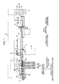
- Fig. 1 is an enlarged plan view of a part of a loom including a selvage forming apparatus according to an embodiment of the present invention.
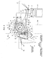
- Fig. 2 is a side view of the selvage forming apparatus according to the embodiment of the present invention.
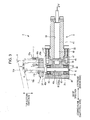
- Fig. 3 is a sectional side view of a selvage-yarn-path switching device.
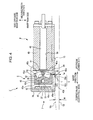
- Fig. 4 is a sectional view of Fig. 3 taken along line IV-IV.
- Fig. 5 is a plan view of the selvage forming apparatus.
- Fig. 6 is a side view illustrating an operation of a selvage shedding device in a state in which a shed that has been formed by selvage yarns is closed.
- Fig. 7 is a side view illustrating the operation of the selvage shedding device in a state in which the shed is formed by the selvage yarns.
- Figs. 8A and 8B are plan views illustrating the operation of the selvage-yarn-path switching device, wherein Fig. 8A shows the state in which first selvage yarns 16a and 16b are respectively on a side opposite a warp row side of and the warp row side of a second selvage yarn 16c and Fig. 8B shows the state in which the first selvage yarns 16a and 16b are respectively on the warp row side of and the side opposite the warp row side of the second selvage yarn 16c.
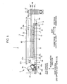
- Fig. 9A to 9C are plan views illustrating examples of leno selvage constructions formed by a selvage forming apparatus according to the present invention, wherein Fig. 9A shows a two-yarn leno selvage construction and Figs. 9B and 9C show three-yarn leno selvage constructions.
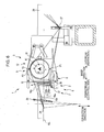
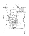
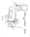
- Fig. 10 is a side view of a selvage forming apparatus.
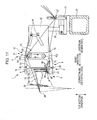
- Fig. 11 is a side view of a selvage forming apparatus.
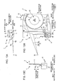
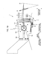
- Figs. 12A, 12B, and 12C are a plan view, a side view, and a front view, respectively, of a selvage-yarn-path switching device included in a selvage forming apparatus.
- Figs. 13A, 13B, and 13C are a plan view, a side view, and a front view, respectively, of a selvage-yarn-path switching device included in a selvage forming apparatus.
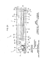
- Figs. 14A and 14B are a front view and a side view, respectively, of a selvage-yarn-path switching device included in a selvage forming apparatus.
- Figs. 15A and 15B are a front view and a side view, respectively, of a selvage-yarn-path switching device included in a selvage forming apparatus.
- Fig. 16 is a side view of a selvage forming apparatus.
- Fig. 17 is a side view of a selvage forming apparatus.
- Fig. 18 is a side view of a selvage forming apparatus.
- Fig. 19 is a side view of a selvage forming apparatus.
- Fig. 20 is a side view of a selvage forming apparatus.
- Fig. 21 is a side view of a selvage forming apparatus.
- Figs. 22A and 22B are side views of a selvage forming apparatus, wherein Fig. 22A shows the state in which a shed is opened and Fig. 22B shows the state in which the shed is closed.
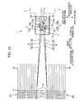
- Fig. 23 is a side view of a selvage forming apparatus.
- a direction parallel to a direction in which warp yarns 18 are moved is defined as a "warp direction”.
- a warp beam side that is, a warp let-off side (not shown) from which the warp yarns 18 are fed and a cloth fell side in the warp direction are defined as an "upstream side” and a “downstream side", respectively.
- a direction in which a weft yarn 17 travels is defined as a "weaving-width direction”.
- the weaving-width direction is referred to also as a "left-right direction”.
- Fig. 1 is an enlarged plan view of a part of a loom including a selvage forming apparatus 1 according to the embodiment of the present invention.
- the selvage forming apparatus 1 is provided near each of cloth edges 19 at a weft insertion side and a weft arrival side in the weaving-width direction.
- the selvage forming apparatuses 1 at the weft insertion side and the weft arrival side have the same structure except that components thereof are arranged and shaped symmetrically in the weaving-width direction. Therefore, Fig. 1 illustrates only the selvage forming apparatus 1 at the weft insertion side and the structure of the loom therearound, and only the selvage forming apparatus 1 at the weft insertion side will be explained in the following description.
- the selvage forming apparatus 1 forms a three-yarn leno selvage construction by using three selvage yarns 16, which include two first selvage yarns 16a and 16b and a single second selvage yarn 16c.
- the bobbins 22 include two bobbins 22a and 22b for the first selvage yarns 16a and 16b, respectively, and a single bobbin 22c for the second selvage yarn 16c.
- Each of the three bobbins 22 is rotatably supported by a bobbin stand 23 that is fixedly arranged on a frame 20 of the loom.
- the bobbins 22 are located upstream of the selvage forming apparatus 1 in the warp direction.
- the bobbins 22 may instead be located downstream of the selvage forming apparatus 1, and even be located downstream of a cloth fell 24 if possible.
- the selvage yarns 16 pulled from the bobbins 22 pass through a tenser device 25 that adjusts the tension applied to each selvage yarn 16, and are guided to the selvage forming apparatus 1 according to the embodiment of the present invention. Then, the selvage yarns 16 extend to the cloth fell 24 through between reed dents of a reed 29.
- the selvage forming apparatus 1 is supported at a location upstream of a heald frame group 28 by the frame 20 at the weft insertion side of the loom with a stand 30 provided therebetween.
- the stand 30 stands on a cross beam member 21 that extends between the frame 20 at the weft insertion side of the loom and a frame (not shown) at the weft arrival side of the loom.
- Each heald frame 28a included in the heald frame group 28 has a space for receiving the selvage forming apparatus 1 between a heald 28b that is closest to the cloth edge and a side frame 28c of the heald frame 28a.
- a part of the selvage forming apparatus 1 is inserted through that space from the upstream side so that the selvage forming apparatus 1 is disposed between the heald 28b closest to the cloth edge and the side frame 28c of the heald frame 28a in the weaving-width direction.
- the selvage forming apparatus 1 includes a selvage-yarn-path switching device 2 and a selvage shedding device 3.
- the selvage-yarn-path switching device 2 switches paths of the first selvage yarns 16a and 16b between two positions, which are on the warp row side of and the side opposite the warp row side of the second selvage yarn 16c in the weaving-width direction.
- the selvage shedding device 3 moves a path of the second selvage yarn 16c between two positions, which are on the upper side of and the lower side of the first selvage yarns 16a and 16b in a top-bottom direction.
- the selvage forming apparatus 1 further includes a selvage yarn guide 27 and a regulating member 15.
- the selvage yarn guide 27 regulates the path of the second selvage yarn 16c in the top-bottom direction.
- the regulating member 15 regulates the path of the second selvage yarn 16c in the weaving-width direction.
- the selvage forming apparatus 1 includes a support frame 32 that is fixed to the stand 30.
- the selvage-yarn-path switching device 2 and the selvage shedding device 3 are attached to the support frame 32.
- the selvage-yarn-path switching device 2 is located upstream of the reed 29 in the warp direction.
- the selvage shedding device 3 is located upstream of the selvage-yarn-path switching device 2 and downstream of the selvage yarn guide 27 in the warp direction.
- the selvage forming apparatus 1 includes plate-shaped guard members 33 that are provided on the support frame 32 at the side adjacent to the healds in order to prevent the selvage-yarn-path switching device 2 and the selvage shedding device 3 from contacting the heald 28b closest to the cloth edge (not shown).
- the guard members 33 are attached to the support frame 32 with respective stays (not shown) and bolts 34, and extend over a region in which the selvage-yarn-path switching device 2 and the selvage shedding device 3 are present in the warp direction.
- the selvage-yarn-path switching device 2 will be described in detail with reference to Figs. 2 to 4 .
- the selvage-yarn-path switching device 2 switches the paths of the two first selvage yarns 16a and 16b between positions on the left and right sides of the path of the second selvage yarn 16c in the weaving-width direction (see Figs. 8A and 8B ).
- the selvage-yarn-path switching device 2 mainly includes a main block 35 that is fixed to the frame 20 with the support frame 32 illustrated in Fig.
- a support shaft 36 that serves as a support member 6 and that is rotatably supported by the main block 35; a base member 37 that serves as a displacement member 7 and that is supported by the support shaft 36; two selvage-yarn guide rods 38a and 38b that serve as selvage-yarn guide members 5 and that stand on the base member 37; and a first drive device 8 that swings the base member 37 around an axis of the support shaft 36 by rotating the support shaft 36.
- the main block 35 is a block-shaped member having a substantially rectangular parallelepiped shape, and has an opening 39 that opens in three side surfaces of the main block 35.
- the main block 35 has an angular U-shape with its open side facing rightward in side view.
- the main block 35 is fixed to a side surface of the support frame 32 illustrated in Fig. 2 at the warp row side in the weaving-width direction in such a manner that a flat surface 40, which is a side surface of the main block 35 that does not have the opening 39, is parallel to the weaving-width direction and is at the most downstream position in the warp direction.
- the main block 35 has bearing-receiving holes 41 that extend therethrough in the top-bottom direction with the opening 39 provided between the bearing-receiving holes 41.
- Bearings 42 are fitted to the respective bearing-receiving holes 41 such that the bearings 42 are separated from each other in the top-bottom direction with the opening 39 provided therebetween and rotation axes thereof extend in the top-bottom direction.
- the support shaft 36 is supported by the bearings 42 in the bearing-receiving holes 41 formed in the main block 35.
- the support shaft 36 is fixedly arranged with respect to the frame of the loom by the bearings 42 and the main block.
- the support shaft 36 is rotatably supported by the main block 35 such that the axis thereof extends in the top-bottom direction (in a direction that crosses the weaving-width direction). A part of the support shaft 36 is exposed to the outside at the opening 39 between the bearings 42.
- the support shaft 36 has a length that is greater than the height (dimension in the axial direction of the bearing-receiving holes 41) of the main block 35, and is assembled to the main block 35 so as to project from the top surface of the main block 35.
- the base member 37 is assembled to the portion of the support shaft 36 that projects from the main block 35 such that the base member 37 is not rotatable relative to the support shaft 36. Thus, the base member 37 is supported by the support shaft 36 such that the base member 37 is movable relative to the frame of the loom owing to the bearings 42.
- the base member 37 is a flat block-shaped member. Through holes 43a and 43b and a through hole 43c for receiving the two selvage-yarn guide rods 38a and 38b and the support shaft 36, respectively, are formed in the base member 37 so as to extend through the base member 37 in the thickness direction. As illustrated in Fig. 4 , the through holes 43a and 43b are formed so as to be equally spaced from the through hole 43c.
- the base member 37 is assembled to the support shaft 36 by fitting the support shaft 36 to the through hole 43c such that the through holes 43a and 43b are on the warp row side of the through hole 43c in the weaving-width direction.
- the selvage-yarn guide rods 38a and 38b are rod-shaped members having eyelets 4, through which the first selvage yarns 16a and 16b are inserted, at positions near the top ends thereof.
- the bottom ends of the selvage-yarn guide rods 38a and 38b are inserted through the through holes 43a and 43b, respectively, in the base member 37 so that the selvage-yarn guide rods 38a and 38b stand on the base member 37 in a direction parallel to the axis of the support shaft 36.
- the first selvage yarn 16a is inserted through the eyelet 4 in the selvage-yarn guide rod 38a, and the first selvage yarn 16b is inserted through the eyelet 4 in the selvage-yarn guide rod 38b.
- the two selvage-yarn guide rods 38a and 38b have different lengths (dimensions in the direction in which they extend).
- the selvage-yarn guide rod 38b is shorter than the selvage-yarn guide rod 38a. More specifically, the lengths of the selvage-yarn guide rods 38a and 38b are set so that, in the state in which the two selvage-yarn guide rods 38a and 38b are assembled to the base member 37, the tip end of the selvage-yarn guide rod 38b is below the straight line that connects the bottom end of the eyelet 4 in the selvage-yarn guide rod 38a and the cloth fell 24 in the top-bottom direction. Therefore, as illustrated in Fig.
- the paths of the first selvage yarns 16a and 16b do not cross each other in the top-bottom direction in a region between the cloth fell 24 and the selvage-yarn guide rods 38a and 38b, and the first selvage yarn 16a is always above the first selvage yarn 16b.
- first selvage yarn guides 44a and 44b are attached to the base member 37.
- the first selvage yarn guides 44a and 44b serve to position the paths of the first selvage yarns 16a and 16b below the path of the second selvage yarn 16c in a region upstream of the selvage-yarn-path switching device 2.
- the first selvage yarn guides 44a and 44b are provided to prevent the second selvage yarn 16c from interfering with the first selvage yarns 16a and 16b when a shed is formed. This will be described in more detail below.
- the first drive device 8 includes a swing block 45, two permanent magnets 46 and 47, an electromagnet 48, an electromagnet housing 49, and a stopper member 50.
- the swing block 45 is a block-shaped member having a pentagonal shape that is axially symmetrical in plan view.
- the swing block 45 has three side surfaces 45a, each adjacent pair of which are orthogonal to each other, two oblique surfaces 45b that continue from two of the three side surfaces 45a that are parallel to each other (side surfaces in the width direction), and top and bottom surfaces that are parallel to each other.
- the swing block 45 is axially symmetrical about an axis of symmetry 51 that extends through the boundary between the two oblique surfaces 45b and that is parallel to the side surfaces in the width direction.
- a through hole 45c for receiving the support shaft 36 is formed in the swing block 45 so as to extend though the swing block 45 in the thickness direction.
- the center of the through hole 45c is positioned on the axis of symmetry 51.
- the portion of the support shaft 36 that is exposed at the opening 39 of the main block 35 is inserted through the through hole 45c, and the swing block 45 is fixed to the support shaft 36 such that the swing block 45 is not rotatable relative to the support shaft 36.
- the swing block 45 included in the first drive device 8 is connected to the base member 37 by the support shaft 36.
- Attachment holes 52 and 53 for the permanent magnets 46 and 47, respectively, are formed in the two oblique surfaces 45b of the swing block 45.
- the permanent magnets 46 and 47 are inserted into the attachment holes 52 and 53, respectively, in the swing block 45 and are fixed to the swing block 45 by means of, for example, an adhesive.
- the permanent magnets 46 and 47 have the same cylindrical shape, and are attached to the attachment holes 52 and 53, respectively, in the swing block 45 such that the polarities thereof are opposite to each other.
- the electromagnet 48 is housed in the electromagnet housing 49.
- the electromagnet housing 49 is fixed to an upstream side surface 54 of the main block 35 (among two side surfaces in a direction orthogonal to the width direction, the side surface in which the opening is formed).
- the electromagnet housing 49 has a substantially rectangular parallelepiped shape, and includes an attachment flange 55 at one end thereof in the longitudinal direction, as illustrated in Fig. 3 .
- the electromagnet housing 49 is fixed to the main block 35 by using the flange 55 such that the longitudinal direction of the electromagnet housing 49 is parallel to the warp direction.
- the first drive device 8 is fixedly arranged with respect to the frame of the loom with the main block 35 provided therebetween.
- a through hole 56 that receives the electromagnet 48 is formed in the electromagnet housing 49 so as to extend through the electromagnet housing 49 in the longitudinal direction, and the electromagnet 48 is fixedly arranged in the through hole 56.
- the polarity of the electromagnet 48 in an excited state is reversed when the direction in which current flows through a coil included in the electromagnet 48 is switched.
- the permanent magnets 46 and 47 which are arranged such that polarities thereof are opposite to each other, are alternately attracted to the electromagnet 48, so that the swing block 45 swings around the axis of the support shaft 36.
- the stopper member 50 is plate-shaped and is fixed to the bottom surface (downstream surface) of the opening 39 in the main block 35.
- the thickness of the stopper member 50 is set so that a gap that allows the swing block 45 to swing is formed between the stopper member 50 and the swing block 45, and so that the swing block 45 comes into contact with the stopper member 50 when the amount of swing movement of the swing block 45 reaches a predetermined amount.
- the swing motion of the swing block 45 based on the excitation of the electromagnet 48 is regulated by the stopper member 50 when the side surface 45a of the swing block 45 at the downstream side comes into contact with the stopper member 50.
- a swingable range of the swing block 45 is between a swing position (swing limit) at which a portion of the side surface 45a of the swing block 45 at the side opposite the warp row side comes into contact with the stopper member 50 and a swing position (swing limit) at which a portion of the side surface 45a of the swing block 45 at the warp row side comes into contact with the stopper member 50.
- the swing positions are determined by the above-described gap and the width of the swing block.
- the base member 37 and the swing block 45 are assembled to the support shaft 36 so that, when the axis of symmetry 51 of the swing block 45 is parallel to the warp direction, a line segment L that connects the centers of the through holes 43a and 43b in the base member 37 is at an angle ⁇ with respect to the warp direction.
- the angle ⁇ is set in association with the path of the second selvage yarn 16c, which will be described below. This will be described in more detail below.
- the base member 37 swings around the axis of the support shaft 36 (center of the through holes 43c and 45c) such that the position where the line segment L is at the angle ⁇ relative to the warp direction serves as a neutral position.
- the swing block 45 swings by a maximum amount toward the side opposite the warp row side, a portion of the base member 37 on the warp row side of the support shaft 36 is at a most upstream position (state illustrated in Fig. 8A ). This position serves as the upstream swing limit of the base member 37.
- the portion of the base member 37 on the warp row side of the support shaft 36 is at a most downstream position (state illustrated in Fig. 8B ). This position serves as the downstream swing limit of the base member 37.
- the selvage-yarn guide rods 38a and 38b are at the most upstream positions in the warp direction.
- the selvage-yarn guide rod 38a is at a position farthest from the warp row and the selvage-yarn guide rod 38b is at a position closest to the warp row.
- the base member 37 is at the above-described downstream swing limit (in the state illustrated in Fig. 8B )
- the selvage-yarn guide rods 38a and 38b are at the most downstream positions in the warp direction.
- the selvage-yarn guide rod 38a is at a position closest to the warp row and the selvage-yarn guide rod 38b is at a position farthest from the warp row.
- the first drive device 8 drives the displacement member 7 so that the positions of the eyelets 4 in the selvage-yarn guide rods 38a and 38b are periodically switched between two positions which are on the warp row side of and the side opposite the warp row side of the second selvage yarn 16c in the weaving-width direction.
- the selvage shedding device 3 moves the path of the second selvage yarn 16c between positions above and below the paths of the first selvage yarns 16a and 16b in the top-bottom direction.
- the selvage shedding device 3 mainly includes a rotary member 10 including an engagement portion 9 that engages with the second selvage yarn 16c and a second drive device 11 that drives the rotary member 10 so that the rotary member 10 continuously rotates in one direction around a rotation axis.
- the second drive device 11 is formed of a so-called direct-drive motor (hereinafter referred to as a DD motor).
- a DD motor 58 which functions as the second drive device 11, is an inner-rotor motor including an annular stator 59a and a rotor 59b arranged such that the outer peripheral surface of the rotor 59b faces the inner peripheral surface of the stator 59a.
- the stator 59a is attached to the support frame 32 illustrated in Fig. 2 such that a rotation axis 60 (see Fig. 5 ) of the DD motor 58 extends in the weaving-width direction. In this manner, the DD motor 58 is fixed to a side surface of the support frame 32 at the warp row side in the weaving-width direction.
- the rotary member 10 is assembled to the rotor 59b of the DD motor 58 such that the rotary member 10 is not rotatable relative to the rotor 59b.
- the rotary member 10 includes a main body 12 that is rotationally driven by the DD motor 58 and an engagement pin 13 that serves as the engagement portion 9 and that projects from the main body 12 toward the warp row side in the weaving-width direction.
- the main body 12 includes a rotating disc 61, which is a disc-shaped thin plate member, and a support stay 63 attached to the rotating disc 61.
- the main body 12 is fixed to the rotor 59b (not shown) of the DD motor 58 at the warp row side of the DD motor 58 in the weaving-width direction such that the center of the rotating disc 61 coincides with the rotation axis 60 of the DD motor 58.
- the main body 12 is rotatable around the rotation axis 60 that extends in the weaving-width direction.
- the main body 12 is fixedly arranged with respect to the frame 20 of the loom by the DD motor 58, and also by the support frame 32 and the stand 30 illustrated in Fig. 2 .
- the engagement pin 13 is attached to the support stay 63 of the rotating disc 61.
- the engagement pin 13 guides the path of the second selvage yarn 16c in the top-bottom direction by engaging with the second selvage yarn 16c, and moves the path of the second selvage yarn 16c in the top-bottom direction.
- the engagement pin 13 is a round, rod-shaped member, and is provided with a flange portion 62 at the warp-row-side end thereof in the weaving-width direction to prevent the second selvage yarn 16c from being released.
- the engagement pin 13 is fixed to a side surface of the support stay 63 at the warp row side in the weaving-width direction such that an axis thereof extends in the weaving-width direction.
- the selvage yarn guide 27 which will be described below, is disposed between the selvage shedding device 3 and the tenser device 25.
- the position of the path of the second selvage yarn 16c in the top-bottom direction in the state in which the engagement pin 13 is omitted (when it is assumed that the engagement pin 13 is not present) is determined by the vertical position of the selvage yarn guide 27 relative to the cloth fell 24 (straight line that extends through the guide position of the selvage yarn guide 27 and the cloth fell 24).
- the path of the second selvage yarn 16c determined by the selvage yarn guide 27 and the cloth fell 24 is such that when the component of the revolution of the engagement pin 13 in the top-bottom direction is upward, the second selvage yarn 16c is pushed upward from below by the engagement pin 13.
- the second selvage yarn 16c moves downward so as to follow the downward movement of the engagement pin 13 owing to the tension of the second selvage yarn 16c.
- the vertical position of the second selvage yarn 16c at the position of the selvage shedding device 3 is determined by the vertical position (position in the top-bottom direction) of the engagement pin 13 that engages with the second selvage yarn 16c. Accordingly, the revolution path of the engagement pin 13 needs to satisfy the following two conditions, and the position of the engagement pin 13 in the radial direction of the rotary member 10 (distance from the center of the rotating disc 61) is determined so as to satisfy these conditions.
- Condition 1 Referring to Fig. 7 , the position of the engagement pin 13, which moves along the revolution path, at the time when the engagement pin 13 is at the lowermost position in the top-bottom direction is defined as a first position P1. At least when the engagement pin 13 is at the first position P1, the path of the second selvage yarn 16c, which engages with the engagement pin 13, is below (closer to the first drive device 8 than) the eyelet 4 in the selvage-yarn guide rod 38b in the top-bottom direction at the position of the selvage-yarn guide rod 38b in the warp direction. This condition needs to be satisfied to form a shed for the weft insertion operation.
- Condition 2 Referring to Fig. 6 , the position of the engagement pin 13, which moves along the revolution path, at the time when the engagement pin 13 is at the uppermost position in the top-bottom direction is defined as a second position P2. At least when the engagement pin 13 is at the second position P2, the path of the second selvage yarn 16c, which engages with the engagement pin 13, is above (farther from the first drive device 8 than) the tip end of the selvage-yarn guide rod 38a in the top-bottom direction at the position of the selvage-yarn guide rod 38a in the warp direction.
- a balancer 14 is provided on the rotary member 10 at a position symmetrical to the engagement pin 13 about the rotation axis 60.
- the balancer 14 includes a balancer stay 64 that is attached to the warp-row-side surface of the rotating disc 61 and a balancer pin 65 that is attached to the balancer stay 64 on the side opposite the warp row side of a region in which the engagement pin 13 extends in the weaving-width direction.
- the balancer stay 64 is a plate-shaped member having substantially the same weight and shape as those of the support stay 63.
- the balancer pin 65 is a round, rod-shaped member having substantially the same weight and shape as those of the engagement pin 13.
- the balancer pin 65 is arranged at a position symmetrical to the engagement pin 13 about the center of the rotating disc 61 (rotation axis 60 of the DD motor).
- the structure of the selvage shedding device 3 has been described.
- parts of the DD motor 58 and the rotary member 10 are disposed in a region in which the heald frames 28a are disposed in the warp direction. The reason for this is as follows.
- a selvage shed is formed of the first selvage yarns 16a and 16b and the second selvage yarn 16c. Since the positions of the first selvage yarns 16a and 16b in the top-bottom direction are fixed, the size of the selvage shed is determined by a swing angle of the second selvage yarn 16c, that is, by an angle between the path of the second selvage yarn 16c at the uppermost position and the path of the second selvage yarn 16c at the lowermost position. In the present embodiment, the swing angle is determined by the diameter of the revolution path and the distance from the cloth fell 24 to the center of the revolution path.
- the swing angle of the second selvage yarn 16c is determined by the distance from the cloth fell 24 to the first position P1 in the warp direction. Therefore, when the distance from the cloth fell 24 to the first and second positions P1 and P2 is large, the swing angle is small and a shed having a desired size for the weft insertion operation cannot be formed.
- the size of the shed may be increased by moving the center of the revolution path (center of the rotary member 10) to a lower position to move the first position P1 to a lower position. However, when the center of the revolution path is moved to a lower position, the second position P2 is also moved to a lower position, and Condition 2 cannot be satisfied.
- the size of the shed may also be increased by increasing the size of the revolution path, more specifically, by increasing the distance from the center of the rotary member 10 to the engagement pin 13 or increasing the diameter of the rotor 59b of the DD motor 58 or the rotary member 10.
- the size of the revolution path is increased, the inertia of rotation of the engagement pin 13, the rotor 59b of the DD motor 58, and the main body 12 increases, and it becomes difficult to increase the speed of the loom.
- the size of the selvage shedding device 3 increases and the arrangement of the selvage forming apparatus 1 in the loom is limited.
- the selvage shedding device 3 is arranged such that a part thereof is positioned in a region in which the heald frames 28a are disposed, as illustrated in Figs. 1 and 2 , to position the revolution path as close to the cloth fell 24 as possible in the warp direction.
- the selvage shedding device 3 in the warp direction since the selvage-yarn-path switching device 2 is disposed downstream of the selvage shedding device 3, the position of the selvage shedding device 3 in the warp direction is set on the basis of the arrangement of the selvage-yarn-path switching device 2.
- the selvage-yarn-path switching device 2 is disposed upstream of the most retracted position of the reed 29 in the warp direction to avoid interference with the reed 29 (reed holder).
- the selvage shedding device 3 is disposed at a position closest to the cloth fell in consideration of the above-described factors, and is arranged such that a part thereof is disposed in the region in which the heald frames 28a are disposed.
- the swing angle of the second selvage yarn 16c is made as large as possible without increasing the size of the revolution path, so that a selvage shed having a desired size is formed by the first selvage yarns 16a and 16b and the second selvage yarn 16c.
- the selvage yarn guide 27 is provided between the selvage shedding device 3 and the tenser device 25.
- the second selvage yarn 16c engages with an upper portion of the engagement pin 13, and is guided to the cloth fell 24.
- the path of the second selvage yarn 16c is moved in the top-bottom direction by causing the second selvage yarn 16c to engage with the engagement pin 13, which moves in the top-bottom direction. Accordingly, the following condition needs to be satisfied to set the size of the shed formed by the second selvage yarn 16c at a maximum when the engagement pin 13 is at the first position P1.
- the position of the path of the second selvage yarn 16c in the top-bottom direction in the state in which the engagement pin 13 is omitted (in the state in which the second selvage yarn 16c is directly guided from the selvage yarn guide 27 to the cloth fell 24) at the position of the selvage shedding device 3 needs to be below or at substantially the same level as the engagement pin 13 at the first position P1.
- the path of the second selvage yarn 16c needs to be below the selvage shedding device 3 in a region upstream of the selvage shedding device 3.
- the tenser device 25 which defines the path of the second selvage yarn 16c in the region upstream of the selvage shedding device 3, is arranged on the frame of the loom with a dropper device 26, which extends between the left and right frames of the loom, provided therebetween.
- the tenser device 25 guides the second selvage yarn 16c in a region above the selvage shedding device 3.
- the selvage yarn guide 27 is disposed below the selvage shedding device 3 in a region between the selvage shedding device 3 and the tenser device 25.
- the second selvage yarn 16c that has passed through the tenser device 25 is guided by the bottom surface of the selvage yarn guide 27, so that the path of the second selvage yarn 16c is positioned below the selvage shedding device 3.
- the selvage yarn guide 27 is formed of a substantially cylindrical member, and is fixed to one of fixing holes 31a formed in a stay 31, which stands on the cross beam member 21, such that an axis thereof extends in the weaving-width direction.
- the selvage yarn guide 27 is fixedly arranged with respect to the frame of the loom.
- the selvage yarn guide 27 has a guide groove 66c for guiding the second selvage yarn 16c in a peripheral surface thereof.
- the guide groove 66c extends in the circumferential direction of the selvage yarn guide 27.
- the guide groove 66c in the selvage yarn guide 27 regulates the path of the second selvage yarn 16c in the top-bottom direction and the weaving-width direction.
- the selvage yarn guide 27 is arranged such that the guide groove 66c that guides the second selvage yarn 16c is disposed in a region in which the engagement pin 13 of the selvage shedding device 3 extends in the weaving-width direction.
- the selvage yarn guide 27 is also used to guide the first selvage yarns 16a and 16b.
- the selvage yarn guide 27 has not only the guide groove 66c but also guide grooves 66a and 66b for guiding the first selvage yarns 16a and 16b, respectively, in the peripheral surface thereof.
- the guide grooves 66a and 66b are on the side opposite the warp row side of the guide groove 66c in the axial direction of the selvage yarn guide 27, and on the side opposite the warp row side of the region in which the engagement pin 13 extends in the weaving-width direction.
- the three guide grooves 66b, 66a, and 66c for guiding the selvage yarns 16 are arranged in that order from the weft insertion side.
- the first selvage yarns 16b and 16a and the second selvage yarn 16c are guided by the respective three guide grooves in that order from the weft insertion side.
- the guide grooves regulate the paths of the respective selvage yarns 16 in the top-bottom direction and the weaving-width direction.
- the regulating member 15 which is disposed between the selvage shedding device 3 and the selvage-yarn-path switching device 2, regulates the path of the second selvage yarn 16c in the weaving-width direction.
- the regulating member 15 serves to maintain the path of the second selvage yarn 16c at a desired position in the weaving-width direction in a region near the selvage-yarn guide rods 38a and 38b included in the selvage-yarn-path switching device 2.
- the selvage shedding device 3 is disposed on the side opposite the warp row side of the cloth edge 19 in the weaving-width direction.
- the tip end of the engagement pin 13 is also arranged outside (on the side opposite the warp row side of) the cloth edge 19. Accordingly, the guide groove 66c formed in the above-described selvage yarn guide 27 is also located outside the cloth edge 19 in the weaving-width direction.
- the path of the second selvage yarn 16c is at an angle with respect to the warp direction (with respect to the cloth edge 19).
- the rotating disc 61 of the rotary member 10 included in the selvage shedding device 3 is parallel to the warp direction (cloth edge 19). Therefore, when the rotating disc 61 is rotated, the engagement pin 13 moves forward and backward in the warp direction while a distance from the cloth edge 19 in the weaving-width direction is maintained constant.
- the position of the second selvage yarn 16c with respect to the engagement pin 13 in the weaving-width direction differs between the state in which the engagement pin 13 is at the most downstream position and the state in which the engagement pin 13 is at the most upstream position. Accordingly, the second selvage yarn 16c reciprocates along the engagement pin 13 in the weaving-width direction, and the engagement between the second selvage yarn 16c and the engagement pin 13 becomes unstable. Therefore, there is a possibility that the second selvage yarn 16c will be released from the engagement pin 13 when the rotary member 10 (engagement pin 13) is continuously rotated.
- the engagement pin 13 is configured so as to maintain the state in which the second selvage yarn 16c is engaged with the engagement pin 13, the second selvage yarn 16c can be prevented from being released from the engagement pin 13 as described above even when the regulating member 15 is not provided. Even in such a case, although the position of the cloth edge 19 at the cloth fell 24 is constant, the position of the engagement pin 13 moves forward and backward in the warp direction when the rotary member 10 (engagement pin 13) is continuously rotated.
- the angle of the path of the second selvage yarn 16c between the engagement pin 13 and the cloth fell 24 with respect to the warp direction periodically changes, and the path of the second selvage yarn 16c between the engagement pin 13 and the cloth fell 24 vibrates (reciprocates) in the weaving-width direction.
- the engagement pin 13 is moved from the second position P2 to the first position P1
- the path of the second selvage yarn 16c varies while the engagement pin 13 is being moved, and there may be a case in which the second selvage yarn 16c cannot be properly guided into between the selvage-yarn guide rods 38a and 38b of the selvage-yarn-path switching device 2.
- this may be prevented by increasing the swing angle of the base member 37, there is a high possibility that the selvage forming apparatus cannot be used in a high-speed loom when the swing angle of the base member 37 is increased.
- the regulating member 15 is provided between the selvage shedding device 3 and the selvage-yarn-path switching device 2 to reduce the variation in the positional relationship between the engagement pin 13 and the second selvage yarn 16c caused by the rotation of the rotary member 10 and the vibration of the path of the second selvage yarn 16c in the weaving-width direction in a region downstream of (on the cloth fell side of) the selvage shedding device 3.
- the regulating member 15 is a rod-shaped member.
- the regulating member 15 is arranged so as to extend in the top-bottom direction while the bottom end thereof is fitted to a hole formed in the top surface of the electromagnet housing 49 of the first drive device 8 and the top end thereof is supported by a guard stay 68 that supports the guard members 33.
- the dimension of the regulating member 15 in the top-bottom direction is greater than the diameter of the revolution path of the engagement pin 13.
- the regulating member 15 guides the second selvage yarn 16c with the peripheral surface thereof at the side opposite the warp row side.
- the regulating member 15 is arranged such that the end thereof at the side opposite the warp row side is at the same position as the position of the guide groove 66c in the selvage yarn guide 27 in the weaving-width direction. Accordingly, the path of the second selvage yarn 16c is parallel to the warp yarns (cloth edge) in a region between the selvage yarn guide 27 and the regulating member 15, which are on both sides of the selvage shedding device 3.
- the positional relationship between the engagement pin 13 and the path of the second selvage yarn 16c in the weaving-width direction is always constant while the rotary member 10 rotates, and the second selvage yarn 16c can be prevented from being released from the engagement pin 13 when the rotary member 10 continuously rotates.
- the path of the second selvage yarn 16c is parallel to the rotating disc 61 of the rotary member 10. Therefore, when the engagement pin 13 is rotated by the rotation of the main body 12, the second selvage yarn 16c does not move in the weaving-width direction, and moves only in the top-bottom direction. As a result, the above-described vibration of the second selvage yarn 16c does not occur in the region downstream of the selvage shedding device 3.
- the path of the second selvage yarn 16c between the selvage shedding device 3 and the selvage-yarn-path switching device 2 is regulated by the regulating member 15, the path of the second selvage yarn 16c between the regulating member 15 and the cloth fell 24 is at a constant position in the weaving-width direction.
- the path of the second selvage yarn 16c that is guided to the cloth fell 24 by the regulating member 15 is at the angle ⁇ (see Fig. 4 ) with respect to the warp yarns 18 in the weaving-width direction.
- a cover 69 for preventing the second selvage yarn 16c from interfering with the support stay 63 of the engagement pin 13 is attached to a side surface of the rotating disc 61 at the warp row side.
- the cover 69 is an annular disc-shaped member having an outer diameter that is substantially equal to that of the rotating disc 61, and is arranged such that the center thereof coincides with the center of the rotating disc 61.
- the path of the second selvage yarn 16c does not move.
- the path of the first selvage yarn 16a is on one of the left and right sides of the path of the second selvage yarn 16c, and the path of the first selvage yarn 16b is on the other of the left and right sides of the path of the second selvage yarn 16c.
- the paths of the first selvage yarns 16a and 16b are switched by the operation of the selvage-yarn-path switching device 2.
- the positional relationship between the paths of the selvage yarns 16 from the selvage yarn guide 27 to the selvage-yarn-path switching device 2 is such that the second selvage yarn 16c, the first selvage yarn 16a, and the first selvage yarn 16b are arranged in that order from the top.
- the paths of the first selvage yarns 16a and 16b do not move.
- the path of the second selvage yarn 16c is above or below the paths of the first selvage yarns 16a and 16b, and is switched between the positions above and below the first selvage yarns 16a and 16b by the operation of the selvage shedding device 3.
- the second selvage yarn 16c is pulled from the bobbin 22c and is guided to the cloth fell 24 through the tenser device 25, the guide groove 66c of the selvage yarn guide 27, and the selvage shedding device 3 in that order from the upstream side.
- the second selvage yarn 16c extends above the engagement pin 13 of the selvage shedding device 3 in the region between the selvage yarn guide 27 and the cloth fell 24.
- the second selvage yarn 16c is pushed upward in response to a movement of the engagement pin 13 from the first position P1 to the second position P2, and is moved downward while being placed on the engagement pin 13 in response to a movement of the engagement pin 13 from the second position P2 to the first position P1.
- the path of the second selvage yarn 16c is moved in the top-bottom direction by the operation of the selvage shedding device 3 in the region between the selvage yarn guide 27 and the cloth fell 24.
- a shed is formed by the second selvage yarn 16c when the engagement pin 13 is at the first position P1.
- the first selvage yarn 16a is pulled from the bobbin 22a and is guided to the selvage-yarn-path switching device 2 through the tenser device 25 and the guide groove 66a of the selvage yarn guide 27 in that order from the upstream side.
- the first selvage yarn 16a that is guided from the selvage yarn guide 27 to the selvage forming apparatus 1 is guided through a first selvage yarn guide 67a that is fixed to the support frame 32, a first selvage yarn guide 44a that is attached to the base member 37 of the selvage-yarn-path switching device 2, and the eyelet 4 in the selvage-yarn guide rod 38a, and extends to the cloth fell 24.
- the first selvage yarn 16b is pulled from the bobbin 22b and is guided to the selvage-yarn-path switching device 2 through the tenser device 25 and the guide groove 66b of the selvage yarn guide 27 in that order from the upstream side.
- the first selvage yarn 16b that is guided to the selvage-yarn-path switching device 2 is guided through a first selvage yarn guide 67b that is fixed to the support frame 32, a first selvage yarn guide 44b that is attached to the base member 37 of the selvage-yarn-path switching device 2, and the eyelet 4 in the selvage-yarn guide rod 38b, and extends to the cloth fell 24.
- the path of the first selvage yarn 16b is on the side opposite the warp row side of the path of the first selvage yarn 16a and is below the path of the first selvage yarn 16a.
- the first selvage yarn guides 67a and 67b are provided so that the paths of the first selvage yarns 16a and 16b that are guided from the selvage yarn guide 27 to the eyelets 4 in the selvage-yarn guide rods 38a and 38b are regulated to positions below the rotary member 10.
- the first selvage yarn guides 67a and 67b are fixedly arranged in a region between the rotary member 10 and the selvage-yarn-path switching device 2 in the warp direction. The reason why the paths of the first selvage yarns 16a and 16b are positioned below the rotary member 10 is as follows.
- the first selvage yarns 16a and 16b are guided by the selvage yarn guide 27, which is located below the selvage shedding device 3 in the top-bottom direction, in a region on the side opposite the warp row side of the engagement pin 13 in the weaving-width direction in a region upstream of the selvage shedding device 3.
- the eyelets 4 in the selvage-yarn guide rods 38a and 38b, which are located downstream of the selvage shedding device 3, are both located above the first position P1 (lowermost position) of the engagement pin 13.
- the first selvage yarn guides 67a and 67b are provided to regulate the paths of the first selvage yarns 16a and 16b to positions below the rotary member 10.
- the first selvage yarn guides 67a and 67b are disposed on the side opposite the warp row side of the engagement pin 13 of the selvage shedding device 3 in the weaving-width direction and at substantially the same vertical position as that of the first position P1 of the engagement pin 13 in the top-bottom direction.
- the first selvage yarn guide 67b is disposed on the side opposite the warp row side of the first selvage yarn guide 67a in the weaving-width direction and on the downstream side of the first selvage yarn guide 67a in the warp direction.
- the first selvage yarn guide 67b is located below the first selvage yarn guide 67a in the top-bottom direction.
- the first selvage yarn guides 44a and 44b are provided on the top surface of the base member 37 of the selvage-yarn-path switching device 2 to prevent the first selvage yarns 16a and 16b that are guided from the first selvage yarn guides 67a and 67b to the eyelets 4 in the selvage-yarn guide rods 38a and 38b, respectively, from interfering with the second selvage yarn 16c.
- first selvage yarn guides 67a and 67b guide the first selvage yarns 16a and 16b, respectively, at fixed positions in a region upstream of the selvage-yarn-path switching device 2 (selvage-yarn guide rods 38a and 38b).
- the eyelets 4 in the selvage-yarn guide rods 38a and 38b are swung by the base member 37 in a region downstream of the first selvage yarn guides 67a and 67b.
- one or the other of the first selvage yarns 16a and 16b passes through a position where it crosses the path of the second selvage yarn 16c in the weaving-width direction in a region between the first selvage yarn guide 67a and the selvage-yarn guide rod 38a or between the first selvage yarn guide 67b and the selvage-yarn guide rod 38b.
- the second selvage yarn 16c when the second selvage yarn 16c is moved downward in response to the movement of the engagement pin 13, the second selvage yarn 16c interferes with one of the first selvage yarns 16a and 16b and cannot be moved to an intended position. As a result, a selvage shed having the desired size cannot be formed.
- the first selvage yarn guides 44a and 44b are arranged near the selvage-yarn guide rods 38a and 38b, respectively, on the base member 37 in the present embodiment.
- the first selvage yarn guides 44a and 44b regulate the paths of the first selvage yarns 16a and 16b from the first selvage yarn guides 67a and 67b to positions near the bottom ends of the selvage-yarn guide rods 38a and 38b, respectively, to positions below the path of the second selvage yarn 16c at the lowermost position.
- the first selvage yarn guides 44a and 44b are fixed to the base member 37 and swing together with the base member 37 (the selvage-yarn guide rods 38a and 38b). Therefore, both when the base member 37 is at the upstream swing limit and the downstream swing limit, the paths of the first selvage yarns 16a and 16b are below the lowermost position of the second selvage yarn 16c in the regions from the first selvage yarn guides 67a and 67b to the first selvage yarn guides 44a and 44b, respectively.
- One of the first selvage yarns 16a and 16b that travels along the path that crosses the path of the second selvage yarn 16c in the weaving-width direction is caused to extend under the second selvage yarn 16c and is bent upward by the first selvage yarn guide 44a or the first selvage yarn guide 44b.
- the first selvage yarns 16a and 16b are guided to the eyelets 4 in the selvage-yarn guide rods 38a and 38b without interfering with the path of the second selvage yarn 16c at the lowermost position.
- the base member 37 is assembled to the support shaft 36 in the following manner. That is, when the axis of symmetry 51 of the swing block 45 is parallel to the warp direction (when the base member 37 is at the neutral position in the swingable range thereof), the line segment L that connects the centers of the through holes 43a and 43b in the base member 37 is parallel to the path of the second selvage yarn 16c from the regulating member 15 to the cloth fell 24. In the present embodiment, when the base member 37 is at the neutral position, the line segment L is on the warp row side of the path of the second selvage yarn 16c in the weaving-width direction.
- the amount by which the swing block 45 swings may be adjusted so that the middle position of the line segment L is located on the path of the second selvage yarn 16c in top view when the base member 37 is at the upstream or downstream swing limit. Accordingly, as illustrated in Figs. 8A and 8B , the selvage-yarn guide rods 38a and 38b may be equally separated from the second selvage yarn 16c in top view when the base member 37 is at the upstream and downstream swing limits. As a result, the second selvage yarn 16c can be prevented from interfering with the selvage-yarn guide rods 38a and 38b, and reliably moved in the top-bottom direction to form a selvage shed having the desired size.
- the selvage yarn guide 27 according to the present embodiment illustrated in Fig. 5 has the guide grooves 66 that guide the respective selvage yarns 16.
- the selvage yarn guide is not limited to this.
- selvage yarn guides having eyelets for receiving the selvage yarns 16 may be provided for the respective selvage yarns 16 in place of the selvage yarn guide 27 having the guide grooves 66, and the selvage yarns 16 may be guided by inserting the selvage yarns 16 through the eyelets in the respective selvage yarn guides.
- the DD motor 58 included in the selvage shedding device 3 is driven so that the rotary member 10 (engagement pin 13) rotates through one revolution clockwise when viewed from the warp row side in the weaving-width direction each time the loom main shaft rotates through one revolution.
- the phase relationship between the rotation angle of the loom main shaft and that of the engagement pin 13 that moves along the revolution path is set so that the engagement pin 13 is at a middle position of a movement path from the second position P2 to the first position P1 when the main shaft angle is 0°, at which beating-up motion for the weft yarn is performed.
- the phase relationship between the rotation angle of the loom main shaft and that of the engagement pin 13 that moves along the revolution path is not limited to this, and the phase of the rotary member 10 with respect to the main shaft of the loom may be changed as necessary.
- the time at which the base member 37 is swung from one of the upstream and downstream swing limits to the other is set to the time at which the engagement pin 13 reaches the second position in the selvage shedding device 3.
- the above-described partial path of the second selvage yarn 16c moves to a position below the first selvage yarns 16a and 16b, and the selvage shed is formed between the second selvage yarn 16c and the first selvage yarns 16a and 16b.
- the size of the selvage shed is at a maximum at the time when the engagement pin 13 reaches the first position P1.
- the second selvage yarn 16c extends through a space between the selvage-yarn guide rods 38a and 38b in the warp direction.
- the weft insertion operation is started when the rotation angle of the loom main shaft reaches the weft insertion start angle. Accordingly, the weft yarn is inserted into the selvage shed.
- the leading end of the inserted weft yarn passes through the selvage shed at the weft insertion side immediately after the start of the weft insertion operation, travels through the warp shed, and reaches the selvage shed at the weft arrival side (not shown) after passing the position of the cloth edge at the weft arrival side.
- the driving operation of the DD motor 58 included in the selvage forming apparatus 1 at the weft insertion side is controlled so that the size of the selvage shed is greater than or equal to the size large enough for the weft insertion operation (required size) at least over the entire weft insertion period.
- the driving operation of the DD motor 58 included in the selvage forming apparatus 1 at the weft arrival side is controlled so that the size of the selvage shed is greater than or equal to the required size at least at the end of the weft insertion operation.
- the first drive device 8 of the selvage-yarn-path switching device 2 swings the base member 37 around the axis of the support shaft 36 from one of the swing limits to the other. Accordingly, the paths of the first selvage yarns 16a and 16b at the side opposite the warp row side of and the warp row side of the path of the second selvage yarn 16c in the weaving-width direction when viewed from above are switched in the weaving-width direction (see Figs. 8A and 8B ). As a result, the first selvage yarns 16a and 16b are caused to cross (be twisted with) the second selvage yarn 16c in the weaving-width direction.
- the first selvage yarns 16a and 16b are caused to cross the second selvage yarn 16c in the weaving-width direction. Therefore, even when the partial path of the second selvage yarn 16c is moved downward to a position below the first selvage yarns 16a and 16b, the weft yarn is not released from the selvage shed and the state in which the weft yarn is held by the first selvage yarns 16a and 16b and the second selvage yarn 16c is maintained.
- the selvage forming apparatus forms a three-yarn leno selvage construction by using the two first selvage yarns 16a and 16b and one second selvage yarn 16c
- the number of selvage yarns are not limited to three.
- the number of first selvage yarns 16a and 16b may be reduced to one, and a two-yarn leno selvage construction illustrated in Fig. 9A may be formed by using a single first selvage yarn 16a and a single second selvage yarn 16c.
- the selvage-yarn-path switching device 2 may include a single selvage-yarn guide member 5.
- the selvage-yarn-path switching device 2 forms the leno selvage construction illustrated in Fig. 9A or 9B by switching the positions of the eyelets 4 in the selvage-yarn guide members 5 each time the loom main shaft rotates through one revolution, that is, each time the weft insertion operation is performed once.
- the frequency at which the positions of the eyelets 4 are switched is not limited to once every time the weft insertion operation is performed once.
- the selvage-yarn-path switching device 2 may form a leno selvage construction illustrated in Fig.
- the selvage-yarn-path switching device 2 may switch the positions of the eyelets 4 in the selvage-yarn guide members 5 each time the loom main shaft rotates through three or more revolutions.
- the selvage-yarn guide rods 38a and 38b are arranged so as to stand on the top surface of the base member 37 and extend upward in the vertical direction, and the first drive device 8 is disposed below the base member 37.
- the selvage-yarn-path switching device 2 may be vertically inverted, as illustrated in Fig. 11 .
- the selvage-yarn guide rods 38a and 38b may be arranged so as to extend downward in the vertical direction from the bottom surface of the base member 37, and the first drive device 8 may be disposed above the base member 37.
- components corresponding to those in the above-described embodiment are denoted by the same reference numerals as those in the above-described embodiment.
- the size of the shed formed by the selvage yarns 16 is at a maximum when the engagement pin 13 included in the selvage shedding device 3 is at the uppermost position on the revolution path. Therefore, in this example, the uppermost position and the lowermost position of the revolution path of the engagement pin 13 correspond to the first position P1 and the second position P2, respectively, in the above-described embodiment.
- the selvage yarn guide 27 is disposed above the selvage shedding device 3, and the path of the second selvage yarn 16c in the state in which the engagement pin 13 is omitted is above or at substantially the same level as the engagement pin 13 at the uppermost position in the top-bottom direction. Therefore, opposite to the above-described embodiment, when the component of the revolution of the engagement pin 13 in the top-bottom direction is upward, the second selvage yarn 16c moves upward so as to follow the engagement pin 13 owing to the tension of the second selvage yarn 16c, and the path of the second selvage yarn 16c is moved upward to a position where the weft insertion operation can be performed (a shed is formed).
- the direction in which the selvage-yarn guide members 5 extend is not limited to the vertical direction as described above, and may be at an angle relative to the vertical direction and inclined toward the warp direction and/or the weaving-width direction as long as the paths of the first selvage yarns 16a and 16b can be switched without a problem.
- the entire body of the selvage-yarn-path switching device 2 may be inclined (the support member 6 may be inclined with respect to the top-bottom direction (vertical direction) toward the warp direction and/or the weaving-width direction).
- the support member 6 may be oriented in the vertical direction and the selvage-yarn guide members 5 may be inclined with respect to the displacement member 7.
- the positions of the selvage-yarn guide members 5 are switched in the weaving-width direction by swinging the base member 37, which functions as the displacement member 7 to which the selvage-yarn guide members 5 are fixed, around the rotation axis that extends in the vertical direction.
- the structures illustrated in Figs. 12A to 12C to 15A and 15B may instead be used. The structures will be described in more detail.
- displacement members 7 are linearly reciprocated to switch the positions of selvage-yarn guide members 5 in the weaving-width direction.
- components similar to those in the above-described embodiment, for example, components of the selvage shedding device 3, are denoted by the same reference numerals as those in the above-described embodiment.
- a selvage-yarn-path switching device 2 of this example includes actuators 73 that function as first drive devices 8; a groove member 71 in which grooves 70 are formed so as to extend in the weaving-width direction and that functions as a support member 6; and slide bases 72 that support the respective selvage-yarn guide members 5, that are movable in the weaving-width direction along the grooves 70 in the groove member 71, and that function as the displacement members 7.
- First selvage yarn guides 74 are fixed to the groove member 71.
- the actuators 73 linearly move the slide bases 72 in the weaving-width direction along the grooves 70 in the groove member 71 so that the positions of eyelets 4 in the selvage-yarn guide members 5 are switched in the weaving-width direction.
- first selvage yarns 16a and 16b two first selvage yarns (first selvage yarns 16a and 16b) are provided, that is, two selvage-yarn guide members 5 are provided (a three-yarn leno selvage construction is formed).
- the number of grooves 70 in the groove member 71, slide bases 72, and actuators 73 is two so as to correspond to the number of selvage-yarn guide members 5.
- the number of grooves 70, slide bases 72, and actuators 73 may be one.
- first selvage yarn guides 75 are provided in addition to first selvage yarn guides 74 and 67.
- the first selvage yarn guides 75 are arranged below the rotary member 10.
- Figs. 13A to 13C illustrate an example in which a single first selvage yarn is used (a two-yarn leno selvage construction is formed).
- a displacement member 7 is rotationally driven around a rotation axis in one direction to switch the position of a selvage-yarn guide member 5 (eyelet 4) in the weaving-width direction.
- components similar to those in the embodiment illustrated in Figs. 12A to 12C are denoted by the same reference numerals as those in the embodiment illustrated in Figs. 12A to 12C .
- a selvage-yarn-path switching device 2 of this example illustrated in Figs. 13A to 13C includes a servo motor 76 that serves as a first drive device 8; a support shaft 77 that extends in the vertical direction, that is directly connected to an output shaft of the servo motor 76, and that serves as a support member 6; and a disc-shaped base member 78 that is fixed to the support shaft 77, that supports the selvage-yarn guide member 5 with a bearing 80 provided therebetween at a position shifted from the rotation center of the support shaft 77, and that serves as the displacement member 7.
- the servo motor 76 is contained in a main block 81.
- a first selvage yarn guide 79 is fixed to the main block 81.
- the servo motor 76 rotationally drives the disc-shaped base member 78 in one direction so that the selvage-yarn guide member 5 revolves around the rotation axis of the support shaft 77 and the position of the eyelet 4 in the selvage-yarn guide member 5 is switched in the weaving-width direction.
- the servo motor 76 is preferably controlled so as to rotate intermittently.
- the servo motor 76 may instead be controlled so as to rotate continuously.
- two specific positions may be set on both sides (the warp row side and the side opposite the warp row side) of a path of a second selvage yarn 16c in the weaving-width direction.
- the servo motor 76 may be controlled so that the output shaft of the servo motor 76 (the support shaft 77) is rotated through half a revolution to move the selvage-yarn guide member 5 between the two positions each time the main shaft is rotated through one revolution and so that the selvage-yarn guide member 5 is at one of the two positions in a predetermined period during each revolution of the loom main shaft.
- the selvage-yarn guide member 5 may be moved between the two positions while the second selvage yarn 16c is positioned above the top end of the selvage-yarn guide member 5 in the top-bottom direction.
- the output shaft of the servo motor 76 (support shaft 77) is rotated through a single revolution so that the selvage-yarn guide member 5 is rotated through a single revolution around the axis of the support shaft 77 each time the main shaft of the loom rotates through two revolutions.
- the servo motor 76 is controlled so that the time at which the selvage-yarn guide member 5 crosses the path of the second selvage yarn 16c in the weaving-width direction is within the period in which the second selvage yarn 16c is above the top end of the selvage-yarn guide member 5 in the top-bottom direction.
- the selvage-yarn guide member 5 is supported by the disc-shaped base member 78 with the bearing 80 interposed therebetween. Therefore, the selvage-yarn guide member 5 revolves around the axis of the support shaft 77 while rotating so that the eyelet 4 is always oriented in the warp direction owing to the tension of a first selvage yarn 16a. Thus, the first selvage yarn 16a is prevented from being coiled (wound) around the selvage-yarn guide member 5 as a result of the revolution of the selvage-yarn guide member 5.
- Figs. 14A and 14B illustrate an example in which the positions of selvage-yarn guide members 5 (eyelets 4) are switched in the weaving-width direction by swinging the selvage-yarn guide members 5 around a rotation axis that extends in the warp direction.
- components similar to those in the embodiment illustrated in Figs. 12A to 12C are denoted by the same reference numerals as those in the embodiment illustrated in Figs. 12A to 12C .
- a selvage-yarn-path switching device 2 of the present embodiment includes a support shaft 82 that is fixedly arranged on a main-body bracket 83 so as to extend in the warp direction and that functions as a support member 6.
- Swing rods 85 which function as the selvage-yarn guide members 5, are supported by respective end portions of the support shaft 82 in a swingable manner.
- the swing rods 85 have through holes 84 at intermediate positions in the direction in which the swing rods 85 extend, and the support shaft 82 are fitted to the through holes 84 so that the swing rods 85 are supported in a swingable manner.
- the swing rods 85 have elongate holes 86 at the bottom ends (ends opposite to the ends at which the eyelets 4 are formed) thereof.
- the elongate holes 86 are long in the direction in which the swing rods 85 extend and extend through the swing rods 85 in the thickness direction.
- First selvage yarn guides 92 are fixed to the main-body bracket 83.
- a first drive device 8 includes a rotating shaft 87 that is fixedly arranged so as to extend in the warp direction; two crank discs 88 that are integrated with respective end portions of the rotating shaft 87 such that rotation centers thereof are on the axis of the rotating shaft 87 and such that the crank discs 88 are not rotatable relative to each other; swing pins 89 attached to the respective crank discs 88 at positions shifted from the rotation centers of the crank discs 88; a pinion gear 91 that meshes with gear teeth formed on the outer periphery of one of the two crank discs 88 (the upstream crank disc 88 in the illustrated example); and a servo motor 90 that is attached to an output shaft of the pinion gear 91.
- the swing pins 89 are inserted through the elongate holes 86 in the respective swing rods 85, so that the first drive device 8 is connected to the swing rods 85.
- the swing rods 85 in particular, portions of the swing rods 85 below the through holes 84
- the crank discs 88, and the swing pins 89 form a crank mechanism.
- the support shaft 82 that supports the swing rods 85 in a swingable manner corresponds to the support member 6, the portions of the swing rods 85 above the support shaft 82 correspond to the selvage-yarn guide members 5, and the lower portions of the swing rods 85 including the portions supported by the support shaft 82 correspond to displacement members 7.
- the selvage-yarn guide members 5 and the displacement members 7 are integrated together as the swing rods 85.
- the portions of the swing rods 85 corresponding to the displacement members 7 may instead be formed separately from the portions corresponding to the selvage-yarn guide members 5, and the swing rods 85 may be fixed to the displacement members 7 that are formed separately therefrom.
- Figs. 15A and 15B illustrate an example in which selvage-yarn guide members 5 are swung around a support shaft that extends in the warp direction, similar to the example illustrated in Figs. 14A and 14B .
- the support shaft is directly rotated.
- components similar to those in the structure illustrated in Figs. 14A and 14B are denoted by the same reference numerals as those in the structure illustrated in Figs. 14A and 14B .
- a first drive device 8 includes two servo motors 94 for respective swing rods 93 that serve as the selvage-yarn guide members 5.
- the servo motors 94 are fixedly arranged on a main block 95 such that rotation axes of output shafts 94a thereof extend in the warp direction.
- Drive discs 96 are attached to the output shafts 94a of the respective servo motors 94, and the swing rods 93 are arranged so as to stand on the respective drive discs 96.
- First selvage yarn guides 97 are fixed to the main block 95.
- the swing rods 93 are driven so as to swing in a reciprocating manner, so that the positions of eyelets 4 formed in the swing rods 93 are switched between two positions that are on the warp row side of and the side opposite the warp row side of a second selvage yarn 16c in the weaving-width direction.
- the output shafts 94a of the servo motors 94 correspond to support members 6, and the drive discs 96 correspond to displacement members 7.
- the selvage shedding device 3 is configured such that the main body 12 of the rotary member 10 included in the selvage shedding device 3 includes the rotating disc 61, which is a disc-shaped thin plate member, and the support stay 63 attached to the rotating disc 61.
- the structure of the rotary member 10 is not limited to this, and the structures illustrated in Figs. 16 and 17 may instead be used.
- Fig. 16 illustrates an example in which a main body 12 does not include the disc-shaped member according to the above-described embodiment, and includes only a stay 99 that is attached to an output shaft of a servo motor 98, which is provided as a second drive device 11, such that the stay 99 is not rotatable relative to the output shaft.
- a servo motor 98 which is provided as a second drive device 11
- components similar to those in the embodiment illustrated in Figs. 12A to 12C are denoted by the same reference numerals as those in the embodiment illustrated in Figs. 12A to 12C .
- Fig. 17 illustrates an example in which a main body 12 is a belt member 103 that is wound around a drive pulley 101 attached to a drive shaft 100 of a second drive device 11 (not shown) and a driven pulley 102 having a rotation axis that is parallel to the drive shaft 100.
- components similar to those in the example illustrated in Fig. 16 are denoted by the same reference numerals as those in the example illustrated in Fig. 16 .
- the drive pulley 101 and the driven pulley 102 are attached to a support frame 32 such that a part of the path of the belt member 103 wound around the drive pulley 101 and the driven pulley 102 is perpendicular to the top-bottom direction and parallel to the warp direction.
- an engagement portion 9 is formed of an engagement pin 13.
- the engagement pin 13 is fixed to the outer peripheral surface of the belt member 103 such that an axis thereof is parallel to an axis of the drive shaft 100, and is arranged so as to partially project from the belt member 103 in the weaving-width direction.
- the drive pulley 101 is rotationally driven so that the belt member 103 is continuously rotated in one direction. Accordingly, the engagement pin 13 is moved along a revolution path that extends along the outer peripheral surface of the belt member 103.
- the selvage shedding device is configured such that the engagement portion 9, which engages with the second selvage yarn 16c, is formed of the engagement pin 13 that engages with the second selvage yarn 16c at the outer peripheral surface thereof.
- the structure of the engagement portion 9 is not limited to this.
- a member having an eyelet 105, which serves as an engagement portion 9 may be attached to a main body 12 of a rotary member 10 instead of the engagement pin 13, and a second selvage yarn 16c may be inserted through the eyelet 105 so that the second selvage yarn 16c is moved in the top-bottom direction.
- the second selvage yarn 16c is positively (forcedly) moved by the engagement portion 9 in both the upward and downward directions.
- Fig. 18 is a side view of a selvage shedding device 3 viewed from the warp row side
- Fig. 19 is a side view of the selvage shedding device 3 viewed from the side opposite the warp row side.
- the selvage shedding device 3 includes a second drive device 11 that is composed of an inner-rotor DD motor (not shown), as in the above-described embodiment.
- the DD motor is attached to a support frame 108 in such a manner that the rotation axis of the DD motor extends in the weaving-width direction.
- a rotating disc 106 which serves as the main body 12 of the rotary member 10, is attached to a warp-row-side surface of a rotor of the DD motor such that the rotating disc 106 is not rotatable relative to the rotor.
- a first stay 107 is fixed to a warp-row-side surface of the rotating disc 106.
- the first stay 107 includes an end portion having a side surface that is parallel to the warp direction.
- a through hole is formed in the end portion of the first stay 107 so as to extend through the end portion in the weaving-width direction, and a first eyelet member 110 in which the eyelet 105 is formed is attached to the through hole.
- the first eyelet member 110 is a cylindrical member through which the eyelet 105 extends in the axial direction, and has a flange portion for guiding the second selvage yarn 16c at an end thereof in the axial direction.
- the first eyelet member 110 is fitted to the through hole in the first stay 107 such that the flange portion thereof projects from a warp-row-side surface of the first stay 107.
- the second selvage yarn 16c is inserted through the eyelet 105 from the rotating-disc-106 side, is engaged with and bent at the inner peripheral edge of the flange portion of the first eyelet member 110, and is guided toward the cloth fell 24. Therefore, in this example, the eyelet 105 in the first eyelet member 110 corresponds to the engagement portion 9 of the rotary member 10.
- the dimension of the first stay 107 that is, the dimension from an attachment portion of the first stay 107 that is attached to the rotating disc 106 to the tip end, is set so that the revolution path of the eyelet 105 around the rotation axis satisfies conditions 1 and 2 as in the above-described embodiment.
- the path of the second selvage yarn 16c do not interfere with the rotary member 10 in a region upstream of (on the bobbin side of) the eyelet 105. More specifically, it is necessary that there is no component that crosses the path of the second selvage yarn 16c in the weaving-width direction (the first stay 107 in this example) in a region upstream of the eyelet 105.
- a tubular path 111 is provided so as to extend through the selvage shedding device 3 in the weaving-width direction, and the second selvage yarn 16c is inserted through the tubular path 111 from the side opposite the warp row side.
- the second selvage yarn 16c is constantly guided from a position of the rotation axis at the warp row side of the tubular path 111 to the eyelet 105. Accordingly, irrespective of the position of the eyelet 105 on the revolution path, no component crosses the path of the second selvage yarn 16c in the region upstream of the eyelet 105 in the selvage shedding device 3.
- the tubular path 111 includes a cylindrical member (not shown) through which a through hole extends in the axial direction and two second eyelet members 112 that are fitted to the through hole in the cylindrical member at both ends of the through hole.
- the cylindrical member (not shown) is long enough to extend through the rotating disc 106, the DD motor (not shown), and the support frame 108 in the weaving-width direction, and is fixed to the rotating disc 106 so as to extend through the rotating disc 106, the DD motor (not shown), and the support frame 108 such that the axis thereof coincides with the rotation axis of the rotary member 10.
- the second selvage yarn 16c is inserted into the eyelet member 112 at the end of the tubular path 111 on the side opposite the warp row side (back side of the support frame 108), as illustrated in Fig. 19 , and is pulled out from the eyelet member 112 at the end of the tubular path 111 on the warp row side (front side of the support frame 108), as illustrated in Fig. 18 .
- the second selvage yarn 16c is constantly guided from a position of the rotation axis of the DD motor to the eyelet 105, and no component crosses the path of the second selvage yarn 16c in the region upstream of the eyelet 105. In other words, irrespective of the position of the eyelet 105 on the revolution path, the second selvage yarn 16c does not contact the first stay 107 in regions other than the eyelet 105.
- the selvage shedding device 3 includes a second stay 113 arranged on the side opposite the warp row side of the rotating disc 106.
- the second stay 113 is provided to absorb the variation in the length of the partial path of the second selvage yarn 16c from the cloth fell 24 to the first eyelet member 110 due to the rotation of the rotary member 10 (first stay 107).
- the second stay 113 is attached to a side surface of the rotating disc 106 on the side opposite the warp row side, and a through hole is formed in an end portion of the second stay 113 so as to extend though the end portion in the weaving-width direction.
- a third eyelet member 114 having an eyelet is fitted to the through hole.
- the second stay 113 is attached to the rotating disc 106 so that the eyelet in the eyelet member 114 is at the same position as the eyelet in the first eyelet member 110 in the weaving-width direction.
- the path of the second selvage yarn 16c extends through the eyelet in the third eyelet member 114 in a region upstream of the second eyelet members 112 (tubular path 111).
- the variation in the length of the partial path of the second selvage yarn 16c from the cloth fell 24 to the first eyelet member 110 due to the rotation of the rotary member 10 (first stay 107) is absorbed and reduced by the variation in the length of the path of the second selvage yarn 16c in the region upstream of the second eyelet members 112.
- the selvage yarn guide 27 As in the illustrated example, in the case where the second selvage yarn 16c is positively moved in the top-bottom direction by the eyelet 105, which serves as the engagement portion 9, the selvage yarn guide 27 according to the above-described embodiment that determines the path of the second selvage yarn 16c in the state in which the shed is opened is not necessary. More specifically, in the above-described embodiment, the second selvage yarn 16c is passively moved downward by using the tension of the second selvage yarn 16c itself. Therefore, the selvage yarn guide 27 is required to regulate the position of the path of the second selvage yarn 16c in the top-bottom direction in the state in which the shed is opened to a position where the size of the selvage shed is at a maximum.
- the second selvage yarn 16c is inserted through the eyelet 105 and is positively moved in the top-bottom direction. Therefore, the selvage yarn guide 27 according to the above-described embodiment is not necessary. Only a selvage yarn guide having a function of simply guiding the second selvage yarn 16c from the corresponding bobbin to the eyelet 105 is required, and the freedom of arrangement of the selvage yarn guide is increased compared to that in the above-described embodiment.
- an eyelet pin 123 having an eyelet 122 may be provided as the engagement portion 9.
- the structure illustrated in Fig. 21 is similar to that of the above-described embodiment except for the engagement portion 9, and components similar to those of the above-described embodiment are denoted by the same reference numerals.
- the eyelet pin 123 is supported by a support stay 124 of a rotary member 10 such that the axis thereof extends in the weaving-width direction.
- the eyelet pin 123 has an eyelet 122 that extends through the eyelet pin 123 in a direction orthogonal to the axis of the eyelet pin 123 (weaving-width direction) at a position on the warp row side of the position at which the eyelet pin 123 is supported by the support stay 124.
- the eyelet pin 123 is supported by the support stay 124 with a bearing 125 interposed therebetween, and is rotatable around the axis thereof.
- the eyelet pin 123 is attached to the support stay 124 with the bearing 125 interposed therebetween. If the bearing 125 is omitted, the eyelet pin 123 itself serves as a component that crosses the path of the second selvage yarn 16c in the region upstream of the eyelet 122 depending on the orientation of the eyelet 122. Therefore, the second selvage yarn 16c becomes wound around the eyelet pin 123 when the rotary member 10 is rotated.
- the eyelet pin 123 In contrast, in the case where the eyelet pin 123 is supported by the support stay 124 with the bearing 125 interposed therebetween, when the rotary member 10 is rotated, the eyelet pin 123 moves along the revolution path while rotating so that the eyelet 122 is always oriented toward the cloth fell owing to the tension of the second selvage yarn 16c. Owing to the rotation of the eyelet pin 123, there is no component that crosses the path of the second selvage yarn 16c in the region upstream of the eyelet 122. In other words, irrespective of the position of the eyelet pin 123 on the revolution path, the eyelet pin 123 does not contact the second selvage yarn 16c in regions other than the eyelet 122. As a result, the second selvage yarn 16c is prevented from being wound around the eyelet pin 123.
- the engagement pin 13 having a circular cross section is used as the engagement portion 9.
- the cross-sectional shape of the engagement pin is not limited to a circular shape, and may instead be flat as illustrated in Figs. 22A and 22B.
- Figs. 22A and 22B illustrate a selvage forming apparatus 1 having a structure similar to that of the above-described embodiment except for the engagement portion 9, and components similar to those of the above-described embodiment are denoted by the same reference numerals.
- the engagement portion 9 is provided on the support stay 63 that is fixed to the main body 12.
- the support stay 63 may be omitted in the above-described embodiment, and the engagement pin 13 may be attached to the rotating disc 61 that serves as the main body 12.
- the engagement portion 9 may be provided directly on the main body 12.
- an eyelet member 116 which serves as the engagement portion 9, is provided directly on a rotary ring 115 that serves as the main body 12.
- components similar to those in Figs. 18 and 19 are denoted by the same reference numerals as those in Figs. 18 and 19 .
- the main body 12 of the rotary member 10 is formed of an annular rotary ring 115.
- the rotary ring 115 is supported by an inner peripheral surface of an annular bracket (not shown) that is fixed to a support frame 121, and is rotatable relative to the support frame 121.
- the rotary ring 115 which serves as the main body 12, has a through hole that extends through the rotary ring 115 in the weaving-width direction. Eyelet members 116 for guiding the path of the second selvage yarn 16c that is inserted through the through hole are provided at both ends of the through hole.
- the eyelet members 116 are similar to the eyelet member 110 in the example illustrated in Figs. 18 and 19 , and are fitted to both ends of the through hole in the rotary ring 115 such that flange portions thereof project from the side surfaces of the rotary ring 115 in the weaving-width direction. Therefore, similar to the example illustrated in Figs. 18 and 19 , the eyelets in the eyelet members 116 correspond to the engagement portion 9 of the rotary member 10.
- the inner and outer diameters of the rotary ring 115 are set so that the revolution path of the eyelets in the eyelet members 116, which are fitted to the through hole in the rotary ring 115, around the rotation axis satisfies conditions 1 and 2 as in the above-described embodiment.
- the second selvage yarn 16c is inserted into the eyelet member 116 at the side opposite the warp row side (back side of the support frame 121) (not shown) and is pulled out from the eyelet member 116 at the warp row side (front side of the support frame 121), so that the second selvage yarn 16c extends through the rotary ring 115 and is guided toward the cloth fell 24.
- No component that extends in the weaving-width direction is attached to the side surface of the rotary ring 115 on the warp row side or the side surface of the rotary ring 115 on the side opposite the warp row side.
- the rotary member 10 is connected to a second drive device 11 (drive shaft 117) through drive pulleys 118 and 119 and a belt 120.
- the rotary member 10 of the selvage shedding device 3 is directly connected to the DD motor 58 that serves as the second drive device 11 in the above-described embodiment, the rotary member 10 may instead be driven by the second drive device 11 through a transmitting member.
- the rotary ring 115 has a width (dimension in the weaving-width direction) that is larger than that of the above-described bracket.
- the drive pulley 118 is fixed to the outer periphery of a portion of the rotary ring 115 that is on the warp row side of the bracket in the weaving-width direction.
- the drive pulley 118 is connected to the drive pulley 119, which is fixed to the drive shaft 117 of a servo motor (not shown), with the belt 120.
- the driving force of the drive shaft 117 is transmitted to the rotary ring 115 through the drive pulley 119, the belt 120, and the drive pulley 118.
- the servo motor (not shown), the drive shaft 117, the drive pulleys 118 and 119, and the belt 120 correspond to the second drive device 11.
- the eyelets that serve as the engagement portion 9 are not limited to circular holes, and may instead be elongate holes.
- the engagement portion 9 is moved along the revolution path by rotating the rotary member 10 around the rotation axis that extends parallel to the weaving-width direction.
- the rotary member 10 may instead be rotated around a rotation axis that is inclined from the weaving-width direction toward the top-bottom direction and the warp direction within a range in which the movement of the path of the second selvage yarn 16c in the top-bottom direction is not adversely affected.
- the second drive device 11 used to rotate the rotary member 10 is the DD motor 58 of an inner rotor type.
- the second drive device 11 is not limited to this, and may instead be a DD motor of an outer rotor type.
- a servo motor may be used in place of the DD motor, and the rotary member 10 may be directly attached to a rotating shaft of the servo motor.
- the second drive device may be formed of a servo motor and a belt transmission mechanism, and the servo motor may rotate the rotary member 10 through the belt transmission mechanism.
- the rotary member 10 is rotated clockwise when the selvage forming apparatus 1 is viewed from the warp row side in the weaving-width direction.
- the rotary member 10 may instead be rotated counterclockwise.
- the second selvage yarn 16c is bent toward the warp row side in the weaving-width direction at the position of the regulating member 15, and is then guided to the cloth fell 24. In this case, when the second selvage yarn 16c is moved in the top-bottom direction, the second selvage yarn 16c slides along the regulating member 15 and receives a frictional resistance.
- the engagement portion 9 is moved along the downstream revolution path section.
- the engagement portion 9 is moved along the upstream revolution path section.
- the distance between the engagement portion 9 and the regulating member 15, that is, the length of the path of the second selvage yarn 16c between the engagement portion 9 and the regulating member 15, differs between the case in which the rotary member 10 is rotated counterclockwise and the case in which the rotary member 10 is rotated clockwise.
- the second selvage yarn 16c is moved downward while the length of the above-described path is smaller than that in the state in which the engagement portion 9 is at the second position P2.
- the second selvage yarn 16c is moved downward while the length of the above-described path is larger than that in the state in which the engagement portion 9 is at the second position P2.
- the length of the above-described path is smaller than that in the case where the rotary member 10 is rotated clockwise, and therefore the partial path of the second selvage yarn 16c is not easily bent. Even though the second selvage yarn 16c slides along the regulating member 15 and receives a frictional resistance, the second selvage yarn 16c reliably follows the movement of the engagement portion 9 and moves downward. As a result, the selvage shed is quickly formed in response to the movement of the engagement portion 9 when the rotary member 10 is rotated counterclockwise.
- the engagement portion 9 is moved along the upstream revolution path section.
- the engagement portion 9 is moved along the downstream revolution path section.
- the length of the path of the second selvage yarn 16c between the engagement portion 9 and the regulating member 15 differs between the case in which the rotary member 10 is rotated counterclockwise and the case in which the rotary member 10 is rotated clockwise.
- the second selvage yarn 16c is moved upward while the length of the above-described path is larger than that in the state in which the engagement portion 9 is at the first position P1.
- the second selvage yarn 16c is moved upward while the length of the above-described path is smaller than that in the state in which the engagement portion 9 is at the first position P1.
- the length of the above-described path is larger than that in the case where the rotary member 10 is rotated clockwise, and therefore the partial path of the second selvage yarn 16c is easily bent.
- the second selvage yarn 16c slides along the regulating member 15 and receives a frictional resistance, followability of the second selvage yarn 16c to the movement of the engagement portion 9 is reduced. Accordingly, the upward movement of the second selvage yarn 16c is slower than the movement of the engagement portion 9. As a result, the selvage shed is slowly closed in response to the movement of the engagement portion 9 when the rotary member 10 is rotated counterclockwise.
- the selvage forming apparatus 1 includes the regulating member 15 and the rotary member 10 is rotated counterclockwise, the selvage shed is quickly formed and slowly closed in response to the movement of the engagement portion 9. Therefore, there is an advantage that the selvage-shed opening period in which the weft insertion operation can be performed can be made longer than that in the case where the rotary member 10 is rotated clockwise.
- the selvage-yarn-path switching device 2 starts switching the paths of the first selvage yarns 16a and 16b while the vertical position of the partial path of the second selvage yarn 16c at the positions of the selvage-yarn guide members 5 in the warp direction is below the top ends of the selvage-yarn guide members 5, the selvage-yarn guide members 5 may interfere with the second selvage yarn 16c.
- the second selvage yarn 16c is not easily caught as a result of receiving a frictional resistance or being bent when the selvage-yarn guide members 5 interfere with the second selvage yarn 16c, and can be forcedly moved upward and released from between the selvage-yarn guide members 5. Therefore, the time at which the paths of the first selvage yarns 16a and 16b are switched can be made earlier, and the selvage forming apparatus can be used in a loom operated at a higher speed.
- the rotary member may be rotated either clockwise or counterclockwise.
- the relationship between the rotation direction of the rotary member 10 and the shed forming and closing operations is similar to that in the selvage forming apparatus 1 at the weft insertion side described above, except “counterclockwise” is to be read as “clockwise” and “clockwise” is to be read as “counterclockwise” in the above description.
- a part of the selvage shedding device 3 is disposed in a region in which the heald frames 28a are present.
- the rotary member 10 may be disposed upstream of the heald frames 28a in the warp direction within a range in which the weft insertion operation can be performed without a problem.
- the rotation speed of the DD motor 58 and the rotary member 10 of the selvage shedding device 3 may also be relatively low. Therefore, the load applied to the second drive device 11 owing to the inertia of the DD motor 58 and the rotary member 10 is also small. In such a case, the diameter of the revolution path of the engagement portion 9 may be increased by increasing the diameter of the rotary member 10 within a range in which the load applied to the second drive device 11 owing to the inertia is allowable, and the amount of movement of the second selvage yarn 16c in the top-bottom direction may be increased accordingly. Then, the rotary member 10 may be disposed upstream of the heald frames 28a in the warp direction while the size of the shed formed by the selvage yarns 16 is maintained at the size required for the weft insertion operation.
- the regulating member 15 is provided between the selvage shedding device 3 and the selvage-yarn-path switching device 2 in the warp direction.
- the regulating member 15 is provided to prevent the path of the second selvage yarn 16c from vibrating in the weaving-width direction in a region closer to the cloth fell 24 than the selvage shedding device 3 when the rotary member 10 is rotated.
- the regulating member 15 may be omitted.
- the selvage shedding device 3 is preferably configured such that a plane including the revolution path of the engagement portion 9 is parallel to the path of the second selvage yarn 16c from the selvage yarn guide 27 to the cloth fell 24, that is, such that the path of the second selvage yarn 16c is orthogonal to the rotation axis of the rotary member 10.
- the regulating member 15 may be simply omitted when the arrangement of the selvage shedding device 3, the size of the revolution path of the rotary member 10, etc., are such that the above-described vibration is allowable or when the selvage-yarn-path switching device 2 is configured to tolerate the above-described vibration.
- the selvage yarn guide 27 is disposed below the selvage shedding device 3 so that, in the state in which the engagement pin 13 is omitted, the position of the path of the second selvage yarn 16c in the top-bottom direction at the position of the selvage shedding device 3 is below or at substantially the same level as the engagement pin 13 at the first position P1, which is the lowermost position on the revolution path.
- a selvage yarn guide may instead be disposed above the selvage shedding device 3 so that the path of the second selvage yarn 16c at the position of the selvage shedding device 3 is above or at substantially the same level as the engagement pin 13 at the uppermost position on the revolution path.
- the selvage forming apparatus 1 is provided at each of the weft insertion side and the weft arrival side of the loom that weaves a single strip of cloth, that is, at each side of the woven cloth.
- the present invention may also be applied to a center selvage forming apparatus of a double-width loom that simultaneously weaves a plurality of strips of cloth.
- each of the two selvage forming apparatuses 1 disposed between the adjacent strips of woven cloth may include a dedicated selvage-yarn-path switching device 2.
- a single selvage-yarn-path switching device 2 may be provided for the two selvage forming apparatuses 1.
- Fig. 23 illustrates an example in which two selvage shedding devices 3 (not illustrated) and a single selvage-yarn-path switching device 2 are used to form a selvage on each of first woven cloth 127 and second woven cloth 128.
- a three-yarn leno selvage construction is formed on each woven cloth by using three selvage yarns 16 (first selvage yarns 16a and 16b and a second selvage yarn 16c).
- the second selvage yarn 16c for the first woven cloth 127 and the second selvage yarn 16c for the second woven cloth 128 are moved in the top-bottom direction by the respective selvage shedding devices (not illustrated) to form sheds.
- the selvage-yarn-path switching device 2 in this example includes a base member 129 that serves as a displacement member 7.
- Selvage-yarn guide rods 130a and 130b for the first woven cloth 127 and selvage-yarn guide rods 131a and 131b for the second woven cloth 128 are provided on the base member 129 as selvage-yarn guide members 5.
- the base member 129 is fixed to a support shaft 132 that serves as a support member 6.
- a first drive device 8 causes the base member 129 to swing with the support shaft 132 interposed therebetween, thereby switching the paths of the first selvage yarns 16a and 16b.
- first selvage yarn guides 133a, 133b, 134a, and 134b correspond to the first selvage yarn guides 44a and 44b according to the above-described embodiment
- regulating members 135 and 136 correspond to the regulating member 15 according to the above-described embodiment.
- the selvage forming apparatus according to the present invention may be used as a catch-cord selvage forming apparatus.
- the selvage yarns of the selvage forming apparatus according to the present invention that is disposed near a cloth edge and serves as a catch-cord selvage forming apparatus catch an end of the inserted weft yarn to form a selvage construction.
- the selvage construction is cut by a cutter after beating-up motion, and is released from the woven cloth as a catch-cord selvage.
- the catch-cord selvage that has been cut off, the catch-cord selvage being formed of the end of the weft yarn and the selvage yarns, is discarded.
Landscapes
- Engineering & Computer Science (AREA)
- Textile Engineering (AREA)
- Looms (AREA)
Abstract
Description
- The present invention relates to a selvage forming apparatus for a loom, the selvage forming apparatus forming a selvage construction by using at least two selvage yarns pulled from respective bobbins.
- Japanese Unexamined Patent Application Publication (Translation of PCT Application) No.
11-505298 - This apparatus forms a so-called leno selvage construction by using three selvage yarns. The three selvage yarns include two twisting yarns and a single stationary yarn. A shed is formed by switching paths of the two twisting yarns and a path of the single stationary yarn in a top-down direction each time a weft insertion operation is performed. Positions of the two twisting yarns are switched in a left-right direction every other time the weft insertion operation is performed. Thus, the weft yarns are caught by the selvage yarns.
- To move the selvage yarns in the above-described manner, the apparatus according to
Patent Document 1 includes a first swing device and a second swing device. The first swing device swings a single tube-shaped guide needle, which guides the stationary yarn, in the top-bottom direction. The second swing device swings two tube-shaped guide needles, which guide the respective twisting yarns, in the top-bottom direction and includes a rotating mechanism for switching the positions of the two guide needles by rotating the two guide needles around an axis parallel to the guide needles at an intermediate position between the two guide needles. - In the apparatus according to
Patent Document 1, the guide needle of the first swing device and the guide needles of the second swing device are swung in the top-bottom direction so that the guide needle of the first swing device is inserted between the two guide needles of the second swing device, thereby forming a first shed. After a weft yarn is inserted into the first shed, the guide needle of the first swing device is removed from between the two guide needles of the second swing device, so that a second shed is formed. The rotating mechanism rotates and switches the positions of the two guide needles of the second swing device at the position of the second shed, so that the paths of the two twisting yarns are switched in a weaving-width direction. Then, a weft yarn is inserted into the second shed. The apparatus according toPatent Document 1 forms the leno selvage construction by repeating the above-described processes. - In the apparatus according to
Patent Document 1, the guide needle of the first swing device and the guide needles of the second swing device are both swung in the top-bottom direction to cause the selvage yarns to form a shed. In the case where the components are reciprocated in this manner, load is applied to the drive devices owing to the influence of inertia when the moving directions (swing directions) of the components are reversed. - The first swing device simply swings the guide needle thereof in the top-bottom direction, and the guide needle itself is light. Therefore, the load applied to the drive device is small when the amount by which the guide needle is swung is small. In contrast, the second swing device swings not only the two guide needles thereof but also the rotating mechanism in the top-bottom direction, and the influence of inertia of the rotating mechanism, which is heavy, is large. Therefore, a large load is applied to the drive device and there is a high possibility that the drive device for driving the second swing device will be damaged when the apparatus is driven continuously.
- In particular, when the rotation speed of a main shaft of the loom is increased, the load applied to the drive device is also increased owing to the influence of inertia, and the drive device is more easily damaged. Therefore, the speed of the loom including the apparatus according to
Patent Document 1 cannot be increased. - In the apparatus according to
Patent Document 1, the above-described damage to the drive device owing to the inertia may be suppressed when the second swing device including the rotating mechanism is configured to not perform the swinging operation in the top-bottom direction. More specifically, the second swing device may be configured such that the guide needles thereof are only rotated by the rotating mechanism, and the shed may be formed mainly by swinging the guide needle of the first swing device. - However, to form the shed only by the swing movement of the guide needle of the first swing device, it is necessary to increase the swing angle of the first swing device in the top-bottom direction. To perform the shedding motion only by the swinging operation of the first swing device within a period required to perform the shedding motion when both the first and second swing devices perform the swinging operation, it is necessary to increase the swing speed of the first swing device. As a result, the above-described influence of the inertia on the drive device increases, and the load applied to the drive device that drives the first swing device increases accordingly. In this case, there is a high possibility that the drive device for driving the first swing device will be damaged. Therefore, also in this case, the speed of the loom including the apparatus cannot be used.
- Accordingly, an object of the present invention is to provide a selvage forming apparatus that can be used in a high-speed loom.
- To achieve the above-described object, according to the present invention, a selvage forming apparatus for a loom, which forms a selvage construction by using at least two selvage yarns which are pulled from respective bobbins and include a first selvage yarn and a second selvage yarn, is configured as follows. That is, the selvage forming apparatus for the loom includes a selvage-yarn-path switching device disposed on a warp let-off side of a cloth fell in a warp direction and a selvage shedding device disposed on the warp let-off side of the selvage-yarn-path switching device in the warp direction. The selvage-yarn-path switching device includes a selvage-yarn guide member that is rod-shaped and extends at least in a top-bottom direction, the selvage-yarn guide member having an eyelet, through which the first selvage yarn is inserted, at a tip end thereof; a support member that is fixedly arranged with respect to a frame of the loom; a displacement member that supports the selvage-yarn guide member and that is supported by the support member so as to be movable with respect to the frame of the loom so that a position of the selvage-yarn guide member in a weaving-width direction is capable of being switched; and a first drive device that is fixedly arranged with respect to the frame of the loom and connected to the displacement member, the first drive device driving the displacement member so as to periodically switch a position of the eyelet between two positions that are on a warp row side of and a side opposite the warp row side of the second selvage yarn in the weaving-width direction. The selvage shedding device includes a rotary member that is fixedly arranged with respect to the frame of the loom so as to be rotatable around a rotation axis that extends in a direction that crosses the top-bottom direction, the rotary member including an engagement portion that is separated from the rotation axis and that engages with the second selvage yarn to move a path of the second selvage yarn; and a second drive device that rotationally drives the rotary member continuously in one direction around the rotation axis. The selvage shedding device is configured so that, when the second drive device rotationally drives the rotary member, the engagement portion is moved along a revolution path including a position at which the path of the second selvage yarn is closer to the first drive device than the eyelet in the top-bottom direction at least at a position of the selvage-yarn guide member in the warp direction, and a position at which the path of the second selvage yarn is farther from the first drive device than the tip end of the selvage-yarn guide member in the top-bottom direction at least at the position of the selvage-yarn guide member in the warp direction.
- With regard to the "selvage-yarn guide member", "extends at least in a top-bottom direction" means that the extending direction of the selvage-yarn guide member is not limited to the top-bottom direction. As long as the extending direction includes a component in the top-bottom direction, as in the case where, for example, the extending direction is inclined or bent, the path of the first selvage yarn may be moved in the weaving-width direction and switched with respect to the path of the second selvage yarn that moves in the top-bottom direction. Therefore, all of such directions are included.
- In addition, "fixedly arranged" means that the arrangement of the member is fixed, irrespective of whether the member is rotatable or non-rotatable in that arrangement.
- With regard to the "displacement member", "supported by the support member so as to be movable with respect to the frame of the loom" means that both a case in which the displacement member is fixedly supported by the support member and is moved by a movement of the support member and a case in which the displacement member is movably supported by the support member are included.
- With regard to the "rotary member", "rotation axis that extends in a direction that crosses the top-bottom direction" means that cases in which the rotation axis of the rotary member extends in all directions other than the vertical direction are included. As long as the direction of the rotation axis of the rotary member is not the vertical direction, the engagement portion can be moved in the top-bottom direction by rotationally driving the rotary member, so that the engagement portion can move and switch the path of the second selvage yarn with respect to the path of the first selvage yarn in the top-bottom direction. Therefore, the cases in which the rotation axis extends in all of these directions are included.
- In the selvage forming apparatus according to the present invention, the rotary member may include a main body that is rotationally driven by the second drive device, and an engagement pin that serves as the engagement portion and projects from the main body toward the warp row side in the weaving-width direction, the engagement pin engaging with the second selvage yarn at one side of the second selvage yarn in the top-bottom direction and switching the path of the second selvage yarn by moving the path of the second selvage yarn from one side to the other side of a path of the first selvage yarn.
- The rotary member may further include a balancer at a position symmetrical to the engagement pin about the rotation axis.
- At least a part of the rotary member may be disposed at a position of a heald frame in the warp direction.
- The selvage forming apparatus may further include a regulating member that is disposed at a position closer to the cloth fell than the selvage shedding device in the warp direction and that regulates the path of the second selvage yarn in the weaving-width direction.
- The second drive device may rotationally drive the rotary member in a rotation direction such that, in a period in which the second selvage yarn is moved in a direction for forming a shed between the second selvage yarn and the first selvage yarn in the top-bottom direction, that is, in a direction toward the first drive device in the top-bottom direction, the engagement portion is moved along a part of the revolution path that is closer to the cloth fell than a vertical line that passes though the rotation axis of the rotary member.
- In the selvage forming apparatus for the loom according to the present invention, the selvage shedding device includes the rotary member including the engagement portion that is separated from the rotation axis in a radial direction and the second drive device that rotationally drives the rotary member continuously in one direction around the rotation axis. The second drive device rotationally drives the rotary member so that the engagement portion moves the path of the second selvage yarn in the top-bottom direction and switches the path of the second selvage yarn with respect to the path of the first selvage yarn. Therefore, compared to the structure according to the related art in which the shed is formed by the reciprocating motion of the swing devices, the load applied to the second drive device can be reduced by a large amount. Accordingly, the possibility that the second drive device will be damaged can be reduced. In addition, the second drive device can rotate a rotating shaft at a high speed, so that the selvage shedding apparatus can be operated at a high speed. Therefore, the selvage forming apparatus can be used in a high-speed loom.
- In the case where the engagement portion of the rotary member is formed as the engagement pin that projects from the main body of the rotary member toward the warp row side in the weaving-width direction, the engagement pin can be caused to engage with the second selvage yarn at one side of the second selvage yarn in the top-bottom direction and move the path of the second selvage yarn toward the other side, thereby switching the path of the second selvage yarn in the top-bottom direction. Owing to the engagement pin, unlike the case in which, for example, the engagement portion has an eyelet that extends through the engagement portion in the weaving-width direction of the rotary member and the second selvage yarn is inserted through the eyelet, the path of the second selvage yarn is not bent by a large amount in the weaving-width direction. Therefore, excessive variation in the tension of the second selvage yarn can be suppressed and an appropriate selvage construction can be formed.
- More specifically, when the engagement portion is moved along the revolution path, the engagement portion moves not only in the top-bottom direction but also in the warp direction, and the length of the path of the second selvage yarn from the cloth fell to the engagement portion varies accordingly. In this case, when, for example, the engagement portion has an eyelet that extends through the engagement portion in the weaving-width direction of the rotary member and the second selvage yarn is inserted through the eyelet, the second selvage yarn is bent by a large amount in the weaving-width direction at the eyelet. Therefore, when the length of the path varies as described above, the tension of the second selvage yarn significantly varies owing to frictional resistance (bending resistance) at the bent portion.
- In the case where the engagement portion has the eyelet, the tension of the second selvage yarn may be reduced to suppress the excessive variation in the tension of the second selvage yarn. However, when the tension of the second selvage yarn is reduced, there may be a case in which an appropriate selvage construction cannot be formed.
- In contrast, in the case where the engagement portion of the rotary member is formed of the engagement pin and the engagement pin is engaged with the second selvage yarn at one side of the second selvage yarn in the top-bottom direction, the second selvage yarn can be guided to the cloth fell without being bent by a large amount in the weaving-width direction. Therefore, the frictional resistance applied between the engagement portion and the second selvage yarn can be reduced. Accordingly, even when the length of the path of the second selvage yarn varies as described above, the pulling force generated by the movement of the engagement pin does not easily act on the second selvage yarn and the excess variation in the tension of the second selvage yarn can be suppressed. Since the excess variation in the tension of the second selvage yarn can be suppressed without reducing the tension of the second selvage yarn, an appropriate selvage construction can be reliably formed.
- Since the variation in the tension of the second selvage yarn can be suppressed, the tension of the second selvage yarn can be easily adjusted. In addition, since the engagement pin engages with the second selvage yarn at one side of the second selvage yarn in the top-bottom direction, the operator can more easily connect the second selvage yarn to the engagement portion compared to the case in which the engagement portion has an eyelet that extends through the engagement portion in the weaving-width direction of the rotary member.
- In the case where the rotary member includes the balancer at a position symmetrical to the engagement pin about the rotation axis, a vibratory force generated by the rotation of the engagement pin around the rotation axis may be canceled by a vibratory force generated by the rotation of the balancer around the rotation axis, and vibration of the rotary member can be suppressed. Thus, the load applied to the second drive device owing to the vibration can be reduced, and the rotary member can be rotated by the second drive device at a high speed. Accordingly, the selvage forming apparatus can be used in a loom operated at a higher speed.
- In the case where at least a part of the rotary member is disposed at a position of the heald frame in the warp direction, the distance between the engagement portion and the cloth fell is reduced. Therefore, the swing angle of the path of the second selvage yarn (angle between the path of the second selvage yarn at the uppermost position and the path of the second selvage yarn at the lowermost position) can be increased without increasing the size (diameter) of the revolution path, that is, without increasing the size of the rotary member. Accordingly, the selvage forming apparatus can be used in a loom operated at a higher speed.
- More specifically, for example, when the size of the revolution path is constant, the angle between the line segment connecting the engagement portion to the cloth fell and the horizontal line decreases as the distance between the rotary member and the cloth fell increases. Therefore, the swing angle of the second selvage yarn is larger in the case where at least a part of the rotary member is disposed at a position of the heald frame in the warp direction than in the case where the rotary member is disposed at a position farther from the cloth fell than the position of the heald frame.
- In other words, in the case where the rotary member is disposed at a position farther from the cloth fell than the position of the heald frame, the size of the revolution path (rotary member) needs to be increased to set the swing angle to the above-described swing angle. The swing angle affects the size of the selvage shed. Therefore, when a selvage shed having a desired size is to be formed, the rotary member may be arranged such that at least a part thereof is disposed at the position of the heald frame in the warp direction, so that the selvage shed having the desired size can be formed without increasing the size of the revolution path. In such a case, the size of the rotary member that causes the second selvage yarn to perform the shedding motion can be reduced and the inertia of rotation of the rotary member can be reduced accordingly. As a result, the load applied to the second drive device owing to the inertia can be reduced, so that the selvage forming apparatus can be used in a high-speed loom.
- In the case where the selvage forming apparatus further includes the regulating member that is closer to the cloth fell than the selvage shedding device in the warp direction and that regulates the path of the second selvage yarn in the weaving-width direction, the position of the path of the second selvage yarn in the weaving-width direction can be maintained at a predetermined position at the position of the selvage-yarn guide member in the warp direction. Accordingly, the amount by which the displacement member is moved to periodically switch the path of the first selvage yarn between the two positions that are on the warp row side of and the side opposite the warp row side of the second selvage yarn in the weaving-width direction can be reduced. For example, the swing angle by which the selvage-yarn guide member is swung around the axis of a support shaft can be reduced. Thus, the time required to switch the path of the first selvage yarn can be reduced, so that the selvage forming apparatus can be used in a loom operated at a higher speed. In addition, since the swing angle of the selvage-yarn guide member can be reduced, the size of the first drive device can be reduced accordingly.
- In the case where the selvage forming apparatus includes the regulating member, the second drive device may rotationally drive the rotary member in a rotation direction such that, in a period in which the second selvage yarn is moved in the direction for forming the shed between the second selvage yarn and the first selvage yarn in the top-bottom direction, the engagement portion is moved along a part of the revolution path that is closer to the cloth fell than a vertical line that passes though the rotation axis of the rotary member. In this case, the length of the path of the second selvage yarn between the engagement portion and the regulating member in the above-described period is relatively small, and therefore the path of the second selvage yarn is not easily bent. Accordingly, even when the second selvage yarn slides along the regulating member and receives a frictional resistance, the second selvage yarn reliably follows the movement of the engagement portion. As a result, the period in which the selvage shed formed by the movement of the second selvage yarn toward the first drive device has a desired size can be increased.
-
Fig. 1 is an enlarged plan view of a part of a loom including a selvage forming apparatus according to an embodiment of the present invention. -
Fig. 2 is a side view of the selvage forming apparatus according to the embodiment of the present invention. -
Fig. 3 is a sectional side view of a selvage-yarn-path switching device. -
Fig. 4 is a sectional view ofFig. 3 taken along line IV-IV. -
Fig. 5 is a plan view of the selvage forming apparatus. -
Fig. 6 is a side view illustrating an operation of a selvage shedding device in a state in which a shed that has been formed by selvage yarns is closed. -
Fig. 7 is a side view illustrating the operation of the selvage shedding device in a state in which the shed is formed by the selvage yarns. -
Figs. 8A and 8B are plan views illustrating the operation of the selvage-yarn-path switching device, whereinFig. 8A shows the state in whichfirst selvage yarns second selvage yarn 16c andFig. 8B shows the state in which thefirst selvage yarns second selvage yarn 16c. -
Fig. 9A to 9C are plan views illustrating examples of leno selvage constructions formed by a selvage forming apparatus according to the present invention, whereinFig. 9A shows a two-yarn leno selvage construction andFigs. 9B and 9C show three-yarn leno selvage constructions. -
Fig. 10 is a side view of a selvage forming apparatus. -
Fig. 11 is a side view of a selvage forming apparatus. -
Figs. 12A, 12B, and 12C are a plan view, a side view, and a front view, respectively, of a selvage-yarn-path switching device included in a selvage forming apparatus. -
Figs. 13A, 13B, and 13C are a plan view, a side view, and a front view, respectively, of a selvage-yarn-path switching device included in a selvage forming apparatus. -
Figs. 14A and 14B are a front view and a side view, respectively, of a selvage-yarn-path switching device included in a selvage forming apparatus. -
Figs. 15A and 15B are a front view and a side view, respectively, of a selvage-yarn-path switching device included in a selvage forming apparatus. -
Fig. 16 is a side view of a selvage forming apparatus. -
Fig. 17 is a side view of a selvage forming apparatus. -
Fig. 18 is a side view of a selvage forming apparatus. -
Fig. 19 is a side view of a selvage forming apparatus. -
Fig. 20 is a side view of a selvage forming apparatus. -
Fig. 21 is a side view of a selvage forming apparatus. -
Figs. 22A and 22B are side views of a selvage forming apparatus, whereinFig. 22A shows the state in which a shed is opened andFig. 22B shows the state in which the shed is closed. -
Fig. 23 is a side view of a selvage forming apparatus. - A selvage forming apparatus according to an embodiment of the present invention will now be described with reference to
Figs. 1 to 9 . In the following description, a direction parallel to a direction in whichwarp yarns 18 are moved is defined as a "warp direction". A warp beam side, that is, a warp let-off side (not shown) from which thewarp yarns 18 are fed and a cloth fell side in the warp direction are defined as an "upstream side" and a "downstream side", respectively. A direction in which aweft yarn 17 travels is defined as a "weaving-width direction". When a loom is viewed in a direction from the downstream side to the upstream side, the weaving-width direction is referred to also as a "left-right direction". -
Fig. 1 is an enlarged plan view of a part of a loom including aselvage forming apparatus 1 according to the embodiment of the present invention. Theselvage forming apparatus 1 is provided near each of cloth edges 19 at a weft insertion side and a weft arrival side in the weaving-width direction. Theselvage forming apparatuses 1 at the weft insertion side and the weft arrival side have the same structure except that components thereof are arranged and shaped symmetrically in the weaving-width direction. Therefore,Fig. 1 illustrates only theselvage forming apparatus 1 at the weft insertion side and the structure of the loom therearound, and only theselvage forming apparatus 1 at the weft insertion side will be explained in the following description. -
Bobbins 22 that feedselvage yarns 16 to theselvage forming apparatus 1 are disposed upstream of theselvage forming apparatus 1. Theselvage forming apparatus 1 according to the present embodiment forms a three-yarn leno selvage construction by using threeselvage yarns 16, which include twofirst selvage yarns second selvage yarn 16c. Accordingly, thebobbins 22 include twobobbins first selvage yarns single bobbin 22c for thesecond selvage yarn 16c. Each of the threebobbins 22 is rotatably supported by abobbin stand 23 that is fixedly arranged on aframe 20 of the loom. - In the present embodiment, the
bobbins 22 are located upstream of theselvage forming apparatus 1 in the warp direction. However, when theselvage yarns 16 pulled from therespective bobbins 22 are appropriately routed, thebobbins 22 may instead be located downstream of theselvage forming apparatus 1, and even be located downstream of a cloth fell 24 if possible. - The
selvage yarns 16 pulled from thebobbins 22 pass through atenser device 25 that adjusts the tension applied to eachselvage yarn 16, and are guided to theselvage forming apparatus 1 according to the embodiment of the present invention. Then, theselvage yarns 16 extend to the cloth fell 24 through between reed dents of areed 29. - The
selvage forming apparatus 1 is supported at a location upstream of aheald frame group 28 by theframe 20 at the weft insertion side of the loom with astand 30 provided therebetween. Thestand 30 stands on across beam member 21 that extends between theframe 20 at the weft insertion side of the loom and a frame (not shown) at the weft arrival side of the loom. Eachheald frame 28a included in theheald frame group 28 has a space for receiving theselvage forming apparatus 1 between aheald 28b that is closest to the cloth edge and aside frame 28c of theheald frame 28a. A part of theselvage forming apparatus 1 is inserted through that space from the upstream side so that theselvage forming apparatus 1 is disposed between theheald 28b closest to the cloth edge and theside frame 28c of theheald frame 28a in the weaving-width direction. - The overall structure of the
selvage forming apparatus 1 will now be described with reference toFig. 2 . Theselvage forming apparatus 1 includes a selvage-yarn-path switching device 2 and aselvage shedding device 3. The selvage-yarn-path switching device 2 switches paths of thefirst selvage yarns second selvage yarn 16c in the weaving-width direction. Theselvage shedding device 3 moves a path of thesecond selvage yarn 16c between two positions, which are on the upper side of and the lower side of thefirst selvage yarns selvage forming apparatus 1 according to the present embodiment further includes aselvage yarn guide 27 and a regulatingmember 15. Theselvage yarn guide 27 regulates the path of thesecond selvage yarn 16c in the top-bottom direction. The regulatingmember 15 regulates the path of thesecond selvage yarn 16c in the weaving-width direction. - Referring to
Fig. 2 , theselvage forming apparatus 1 includes asupport frame 32 that is fixed to thestand 30. The selvage-yarn-path switching device 2 and theselvage shedding device 3 are attached to thesupport frame 32. The selvage-yarn-path switching device 2 is located upstream of thereed 29 in the warp direction. Theselvage shedding device 3 is located upstream of the selvage-yarn-path switching device 2 and downstream of theselvage yarn guide 27 in the warp direction. - In the illustrated example, the
selvage forming apparatus 1 includes plate-shapedguard members 33 that are provided on thesupport frame 32 at the side adjacent to the healds in order to prevent the selvage-yarn-path switching device 2 and theselvage shedding device 3 from contacting theheald 28b closest to the cloth edge (not shown). Theguard members 33 are attached to thesupport frame 32 with respective stays (not shown) andbolts 34, and extend over a region in which the selvage-yarn-path switching device 2 and theselvage shedding device 3 are present in the warp direction. - The selvage-yarn-
path switching device 2 will be described in detail with reference toFigs. 2 to 4 . The selvage-yarn-path switching device 2 switches the paths of the twofirst selvage yarns second selvage yarn 16c in the weaving-width direction (seeFigs. 8A and 8B ). As illustrated inFigs. 3 and4 , the selvage-yarn-path switching device 2 mainly includes amain block 35 that is fixed to theframe 20 with thesupport frame 32 illustrated inFig. 2 provided therebetween; asupport shaft 36 that serves as asupport member 6 and that is rotatably supported by themain block 35; abase member 37 that serves as adisplacement member 7 and that is supported by thesupport shaft 36; two selvage-yarn guide rods yarn guide members 5 and that stand on thebase member 37; and afirst drive device 8 that swings thebase member 37 around an axis of thesupport shaft 36 by rotating thesupport shaft 36. - The
main block 35 is a block-shaped member having a substantially rectangular parallelepiped shape, and has anopening 39 that opens in three side surfaces of themain block 35. Themain block 35 has an angular U-shape with its open side facing rightward in side view. Themain block 35 is fixed to a side surface of thesupport frame 32 illustrated inFig. 2 at the warp row side in the weaving-width direction in such a manner that aflat surface 40, which is a side surface of themain block 35 that does not have theopening 39, is parallel to the weaving-width direction and is at the most downstream position in the warp direction. - The
main block 35 has bearing-receivingholes 41 that extend therethrough in the top-bottom direction with theopening 39 provided between the bearing-receivingholes 41.Bearings 42 are fitted to the respective bearing-receivingholes 41 such that thebearings 42 are separated from each other in the top-bottom direction with theopening 39 provided therebetween and rotation axes thereof extend in the top-bottom direction. Thesupport shaft 36 is supported by thebearings 42 in the bearing-receivingholes 41 formed in themain block 35. Thus, thesupport shaft 36 is fixedly arranged with respect to the frame of the loom by thebearings 42 and the main block. - The
support shaft 36 is rotatably supported by themain block 35 such that the axis thereof extends in the top-bottom direction (in a direction that crosses the weaving-width direction). A part of thesupport shaft 36 is exposed to the outside at theopening 39 between thebearings 42. Thesupport shaft 36 has a length that is greater than the height (dimension in the axial direction of the bearing-receiving holes 41) of themain block 35, and is assembled to themain block 35 so as to project from the top surface of themain block 35. Thebase member 37 is assembled to the portion of thesupport shaft 36 that projects from themain block 35 such that thebase member 37 is not rotatable relative to thesupport shaft 36. Thus, thebase member 37 is supported by thesupport shaft 36 such that thebase member 37 is movable relative to the frame of the loom owing to thebearings 42. - The
base member 37 is a flat block-shaped member. Throughholes hole 43c for receiving the two selvage-yarn guide rods support shaft 36, respectively, are formed in thebase member 37 so as to extend through thebase member 37 in the thickness direction. As illustrated inFig. 4 , the throughholes hole 43c. Thebase member 37 is assembled to thesupport shaft 36 by fitting thesupport shaft 36 to the throughhole 43c such that the throughholes hole 43c in the weaving-width direction. - As illustrated in
Fig. 3 , the selvage-yarn guide rods members having eyelets 4, through which thefirst selvage yarns yarn guide rods holes base member 37 so that the selvage-yarn guide rods base member 37 in a direction parallel to the axis of thesupport shaft 36. In the present embodiment, thefirst selvage yarn 16a is inserted through theeyelet 4 in the selvage-yarn guide rod 38a, and thefirst selvage yarn 16b is inserted through theeyelet 4 in the selvage-yarn guide rod 38b. - The two selvage-
yarn guide rods yarn guide rod 38b is shorter than the selvage-yarn guide rod 38a. More specifically, the lengths of the selvage-yarn guide rods yarn guide rods base member 37, the tip end of the selvage-yarn guide rod 38b is below the straight line that connects the bottom end of theeyelet 4 in the selvage-yarn guide rod 38a and the cloth fell 24 in the top-bottom direction. Therefore, as illustrated inFig. 2 , the paths of thefirst selvage yarns yarn guide rods first selvage yarn 16a is always above thefirst selvage yarn 16b. - Referring to
Fig. 3 , first selvage yarn guides 44a and 44b are attached to thebase member 37. The first selvage yarn guides 44a and 44b serve to position the paths of thefirst selvage yarns second selvage yarn 16c in a region upstream of the selvage-yarn-path switching device 2. The first selvage yarn guides 44a and 44b are provided to prevent thesecond selvage yarn 16c from interfering with thefirst selvage yarns - As illustrated in
Figs. 3 and4 , thefirst drive device 8 includes aswing block 45, twopermanent magnets electromagnet 48, anelectromagnet housing 49, and astopper member 50. As illustrated inFig. 4 , theswing block 45 is a block-shaped member having a pentagonal shape that is axially symmetrical in plan view. Theswing block 45 has threeside surfaces 45a, each adjacent pair of which are orthogonal to each other, twooblique surfaces 45b that continue from two of the threeside surfaces 45a that are parallel to each other (side surfaces in the width direction), and top and bottom surfaces that are parallel to each other. Theswing block 45 is axially symmetrical about an axis ofsymmetry 51 that extends through the boundary between the twooblique surfaces 45b and that is parallel to the side surfaces in the width direction. - A through
hole 45c for receiving thesupport shaft 36 is formed in theswing block 45 so as to extend though theswing block 45 in the thickness direction. The center of the throughhole 45c is positioned on the axis ofsymmetry 51. The portion of thesupport shaft 36 that is exposed at theopening 39 of themain block 35 is inserted through the throughhole 45c, and theswing block 45 is fixed to thesupport shaft 36 such that theswing block 45 is not rotatable relative to thesupport shaft 36. Thus, theswing block 45 included in thefirst drive device 8 is connected to thebase member 37 by thesupport shaft 36. Attachment holes 52 and 53 for thepermanent magnets oblique surfaces 45b of theswing block 45. - The
permanent magnets swing block 45 and are fixed to theswing block 45 by means of, for example, an adhesive. Thepermanent magnets swing block 45 such that the polarities thereof are opposite to each other. - The
electromagnet 48 is housed in theelectromagnet housing 49. Theelectromagnet housing 49 is fixed to anupstream side surface 54 of the main block 35 (among two side surfaces in a direction orthogonal to the width direction, the side surface in which the opening is formed). Theelectromagnet housing 49 has a substantially rectangular parallelepiped shape, and includes anattachment flange 55 at one end thereof in the longitudinal direction, as illustrated inFig. 3 . Theelectromagnet housing 49 is fixed to themain block 35 by using theflange 55 such that the longitudinal direction of theelectromagnet housing 49 is parallel to the warp direction. Thus, thefirst drive device 8 is fixedly arranged with respect to the frame of the loom with themain block 35 provided therebetween. - A through
hole 56 that receives theelectromagnet 48 is formed in theelectromagnet housing 49 so as to extend through theelectromagnet housing 49 in the longitudinal direction, and theelectromagnet 48 is fixedly arranged in the throughhole 56. The polarity of theelectromagnet 48 in an excited state is reversed when the direction in which current flows through a coil included in theelectromagnet 48 is switched. When the polarity of theelectromagnet 48 is reversed, thepermanent magnets electromagnet 48, so that theswing block 45 swings around the axis of thesupport shaft 36. - The
stopper member 50 is plate-shaped and is fixed to the bottom surface (downstream surface) of theopening 39 in themain block 35. The thickness of thestopper member 50 is set so that a gap that allows theswing block 45 to swing is formed between thestopper member 50 and theswing block 45, and so that theswing block 45 comes into contact with thestopper member 50 when the amount of swing movement of theswing block 45 reaches a predetermined amount. - The swing motion of the
swing block 45 based on the excitation of theelectromagnet 48 is regulated by thestopper member 50 when theside surface 45a of theswing block 45 at the downstream side comes into contact with thestopper member 50. A swingable range of theswing block 45 is between a swing position (swing limit) at which a portion of theside surface 45a of theswing block 45 at the side opposite the warp row side comes into contact with thestopper member 50 and a swing position (swing limit) at which a portion of theside surface 45a of theswing block 45 at the warp row side comes into contact with thestopper member 50. The swing positions are determined by the above-described gap and the width of the swing block. - In the selvage-yarn-
path switching device 2 having the above-described structure, as illustrated inFig. 4 , thebase member 37 and theswing block 45 are assembled to thesupport shaft 36 so that, when the axis ofsymmetry 51 of theswing block 45 is parallel to the warp direction, a line segment L that connects the centers of the throughholes base member 37 is at an angle α with respect to the warp direction. The angle α is set in association with the path of thesecond selvage yarn 16c, which will be described below. This will be described in more detail below. - When the
swing block 45 swings between the above-described two swing positions (swing limits), thebase member 37 swings around the axis of the support shaft 36 (center of the throughholes swing block 45 swings by a maximum amount toward the side opposite the warp row side, a portion of thebase member 37 on the warp row side of thesupport shaft 36 is at a most upstream position (state illustrated inFig. 8A ). This position serves as the upstream swing limit of thebase member 37. When theswing block 45 swings by a maximum amount toward the warp row side, the portion of thebase member 37 on the warp row side of thesupport shaft 36 is at a most downstream position (state illustrated inFig. 8B ). This position serves as the downstream swing limit of thebase member 37. - When the
base member 37 is at the above-described upstream swing limit (in the state illustrated inFig. 8A ), the selvage-yarn guide rods yarn guide rod 38a is at a position farthest from the warp row and the selvage-yarn guide rod 38b is at a position closest to the warp row.
When thebase member 37 is at the above-described downstream swing limit (in the state illustrated inFig. 8B ), the selvage-yarn guide rods yarn guide rod 38a is at a position closest to the warp row and the selvage-yarn guide rod 38b is at a position farthest from the warp row. Thus, thefirst drive device 8 drives thedisplacement member 7 so that the positions of theeyelets 4 in the selvage-yarn guide rods second selvage yarn 16c in the weaving-width direction. - The
selvage shedding device 3 will now be described in detail with reference toFigs. 2 and5 . Theselvage shedding device 3 moves the path of thesecond selvage yarn 16c between positions above and below the paths of thefirst selvage yarns selvage shedding device 3 mainly includes arotary member 10 including anengagement portion 9 that engages with thesecond selvage yarn 16c and asecond drive device 11 that drives therotary member 10 so that therotary member 10 continuously rotates in one direction around a rotation axis. - The
second drive device 11 according to the present embodiment is formed of a so-called direct-drive motor (hereinafter referred to as a DD motor). Referring toFig. 2 , aDD motor 58, which functions as thesecond drive device 11, is an inner-rotor motor including anannular stator 59a and arotor 59b arranged such that the outer peripheral surface of therotor 59b faces the inner peripheral surface of thestator 59a. Thestator 59a is attached to thesupport frame 32 illustrated inFig. 2 such that a rotation axis 60 (seeFig. 5 ) of theDD motor 58 extends in the weaving-width direction. In this manner, theDD motor 58 is fixed to a side surface of thesupport frame 32 at the warp row side in the weaving-width direction. - The
rotary member 10 is assembled to therotor 59b of theDD motor 58 such that therotary member 10 is not rotatable relative to therotor 59b. In the present embodiment, therotary member 10 includes amain body 12 that is rotationally driven by theDD motor 58 and anengagement pin 13 that serves as theengagement portion 9 and that projects from themain body 12 toward the warp row side in the weaving-width direction. - As illustrated in
Fig. 5 , themain body 12 includes arotating disc 61, which is a disc-shaped thin plate member, and asupport stay 63 attached to therotating disc 61. Themain body 12 is fixed to therotor 59b (not shown) of theDD motor 58 at the warp row side of theDD motor 58 in the weaving-width direction such that the center of therotating disc 61 coincides with therotation axis 60 of theDD motor 58. Themain body 12 is rotatable around therotation axis 60 that extends in the weaving-width direction. Themain body 12 is fixedly arranged with respect to theframe 20 of the loom by theDD motor 58, and also by thesupport frame 32 and thestand 30 illustrated inFig. 2 . - The
engagement pin 13 is attached to the support stay 63 of therotating disc 61. Theengagement pin 13 guides the path of thesecond selvage yarn 16c in the top-bottom direction by engaging with thesecond selvage yarn 16c, and moves the path of thesecond selvage yarn 16c in the top-bottom direction. - In the illustrated example, the
engagement pin 13 is a round, rod-shaped member, and is provided with aflange portion 62 at the warp-row-side end thereof in the weaving-width direction to prevent thesecond selvage yarn 16c from being released. Theengagement pin 13 is fixed to a side surface of the support stay 63 at the warp row side in the weaving-width direction such that an axis thereof extends in the weaving-width direction. When themain body 12 of therotary member 10 is rotationally driven by theDD motor 58, theengagement pin 13 moves along a revolution path having therotation axis 60 at the center. - In the present embodiment, the
selvage yarn guide 27, which will be described below, is disposed between theselvage shedding device 3 and thetenser device 25. The position of the path of thesecond selvage yarn 16c in the top-bottom direction in the state in which the engagement
pin 13 is omitted (when it is assumed that theengagement pin 13 is not present) is determined by the vertical position of theselvage yarn guide 27 relative to the cloth fell 24 (straight line that extends through the guide position of theselvage yarn guide 27 and the cloth fell 24). - In the present embodiment, the path of the
second selvage yarn 16c determined by theselvage yarn guide 27 and the cloth fell 24 is such that when the component of the revolution of theengagement pin 13 in the top-bottom direction is upward, thesecond selvage yarn 16c is pushed upward from below by theengagement pin 13. When the component of the revolution of theengagement pin 13 in the top-bottom direction is downward, thesecond selvage yarn 16c moves downward so as to follow the downward movement of theengagement pin 13 owing to the tension of thesecond selvage yarn 16c. - Therefore, as illustrated in
Fig. 2 , the vertical position of thesecond selvage yarn 16c at the position of theselvage shedding device 3 is determined by the vertical position (position in the top-bottom direction) of theengagement pin 13 that engages with thesecond selvage yarn 16c. Accordingly, the revolution path of theengagement pin 13 needs to satisfy the following two conditions, and the position of theengagement pin 13 in the radial direction of the rotary member 10 (distance from the center of the rotating disc 61) is determined so as to satisfy these conditions. - Condition 1: Referring to
Fig. 7 , the position of theengagement pin 13, which moves along the revolution path, at the time when theengagement pin 13 is at the lowermost position in the top-bottom direction is defined as a first position P1. At least when theengagement pin 13 is at the first position P1, the path of thesecond selvage yarn 16c, which engages with theengagement pin 13, is below (closer to thefirst drive device 8 than) theeyelet 4 in the selvage-yarn guide rod 38b in the top-bottom direction at the position of the selvage-yarn guide rod 38b in the warp direction. This condition needs to be satisfied to form a shed for the weft insertion operation. Here, "at least when theengagement pin 13 is at the first position P1" means that a case in which the path of thesecond selvage yarn 16c reaches a position below theeyelet 4 in the selvage-yarn guide member 5 before theengagement pin 13 reaches the first position P1 is included. - Condition 2: Referring to
Fig. 6 , the position of theengagement pin 13, which moves along the revolution path, at the time when theengagement pin 13 is at the uppermost position in the top-bottom direction is defined as a second position P2. At least when theengagement pin 13 is at the second position P2, the path of thesecond selvage yarn 16c, which engages with theengagement pin 13, is above (farther from thefirst drive device 8 than) the tip end of the selvage-yarn guide rod 38a in the top-bottom direction at the position of the selvage-yarn guide rod 38a in the warp direction. This condition needs to be satisfied to allow the selvage-yarn-path switching device 2 to switch the paths of thefirst selvage yarns yarn guide rod 38a from interfering with thesecond selvage yarn 16c when the paths of thefirst selvage yarns engagement pin 13 is at the second position P2" means that a case in which the path of thesecond selvage yarn 16c reaches a position above the tip end of the selvage-yarn guide member 5 before theengagement pin 13 reaches the second position P2 is included. - As illustrated in
Fig. 5 , in the present embodiment, abalancer 14 is provided on therotary member 10 at a position symmetrical to theengagement pin 13 about therotation axis 60. Thebalancer 14 includes abalancer stay 64 that is attached to the warp-row-side surface of therotating disc 61 and abalancer pin 65 that is attached to the balancer stay 64 on the side opposite the warp row side of a region in which theengagement pin 13 extends in the weaving-width direction. - The balancer stay 64 is a plate-shaped member having substantially the same weight and shape as those of the
support stay 63. Thebalancer pin 65 is a round, rod-shaped member having substantially the same weight and shape as those of theengagement pin 13. Thebalancer pin 65 is arranged at a position symmetrical to theengagement pin 13 about the center of the rotating disc 61 (rotation axis 60 of the DD motor). - The structure of the
selvage shedding device 3 has been described. In theselvage shedding device 3, parts of theDD motor 58 and therotary member 10 are disposed in a region in which the heald frames 28a are disposed in the warp direction. The reason for this is as follows. - As illustrated in
Fig. 7 , in theselvage forming apparatus 1 according to the embodiment of the present invention, a selvage shed is formed of thefirst selvage yarns second selvage yarn 16c. Since the positions of thefirst selvage yarns second selvage yarn 16c, that is, by an angle between the path of thesecond selvage yarn 16c at the uppermost position and the path of thesecond selvage yarn 16c at the lowermost position. In the present embodiment, the swing angle is determined by the diameter of the revolution path and the distance from the cloth fell 24 to the center of the revolution path. - When the diameter of the revolution path of the engagement pin 13 (rotary member 10) is constant and the vertical positions of the first and second positions P1 and P2 in the top-bottom direction are also constant, the swing angle of the
second selvage yarn 16c is determined by the distance from the cloth fell 24 to the first position P1 in the warp direction. Therefore, when the distance from the cloth fell 24 to the first and second positions P1 and P2 is large, the swing angle is small and a shed having a desired size for the weft insertion operation cannot be formed. - The size of the shed may be increased by moving the center of the revolution path (center of the rotary member 10) to a lower position to move the first position P1 to a lower position. However, when the center of the revolution path is moved to a lower position, the second position P2 is also moved to a lower position, and
Condition 2 cannot be satisfied. The size of the shed may also be increased by increasing the size of the revolution path, more specifically, by increasing the distance from the center of therotary member 10 to theengagement pin 13 or increasing the diameter of therotor 59b of theDD motor 58 or therotary member 10. However, when the size of the revolution path is increased, the inertia of rotation of theengagement pin 13, therotor 59b of theDD motor 58, and themain body 12 increases, and it becomes difficult to increase the speed of the loom. In addition, the size of theselvage shedding device 3 increases and the arrangement of theselvage forming apparatus 1 in the loom is limited. - Accordingly, in the present embodiment, the
selvage shedding device 3 is arranged such that a part thereof is positioned in a region in which the heald frames 28a are disposed, as illustrated inFigs. 1 and2 , to position the revolution path as close to the cloth fell 24 as possible in the warp direction. With regard to the arrangement of theselvage shedding device 3 in the warp direction, since the selvage-yarn-path switching device 2 is disposed downstream of theselvage shedding device 3, the position of theselvage shedding device 3 in the warp direction is set on the basis of the arrangement of the selvage-yarn-path switching device 2. The selvage-yarn-path switching device 2 is disposed upstream of the most retracted position of thereed 29 in the warp direction to avoid interference with the reed 29 (reed holder). In the present embodiment, theselvage shedding device 3 is disposed at a position closest to the cloth fell in consideration of the above-described factors, and is arranged such that a part thereof is disposed in the region in which the heald frames 28a are disposed. With this arrangement, in the present embodiment, the swing angle of thesecond selvage yarn 16c is made as large as possible without increasing the size of the revolution path, so that a selvage shed having a desired size is formed by thefirst selvage yarns second selvage yarn 16c. - As described above, in the present embodiment, the
selvage yarn guide 27 is provided between theselvage shedding device 3 and thetenser device 25. Thesecond selvage yarn 16c engages with an upper portion of theengagement pin 13, and is guided to the cloth fell 24. The path of thesecond selvage yarn 16c is moved in the top-bottom direction by causing thesecond selvage yarn 16c to engage with theengagement pin 13, which moves in the top-bottom direction. Accordingly, the following condition needs to be satisfied to set the size of the shed formed by thesecond selvage yarn 16c at a maximum when theengagement pin 13 is at the first position P1. That is, the position of the path of thesecond selvage yarn 16c in the top-bottom direction in the state in which theengagement pin 13 is omitted (in the state in which thesecond selvage yarn 16c is directly guided from theselvage yarn guide 27 to the cloth fell 24) at the position of theselvage shedding device 3 needs to be below or at substantially the same level as theengagement pin 13 at the first position P1. In other words, the path of thesecond selvage yarn 16c needs to be below theselvage shedding device 3 in a region upstream of theselvage shedding device 3. - In the present embodiment, as illustrated in
Fig. 1 , thetenser device 25, which defines the path of thesecond selvage yarn 16c in the region upstream of theselvage shedding device 3, is arranged on the frame of the loom with adropper device 26, which extends between the left and right frames of the loom, provided therebetween. Thetenser device 25 guides thesecond selvage yarn 16c in a region above theselvage shedding device 3. Accordingly, in the present embodiment, theselvage yarn guide 27 is disposed below theselvage shedding device 3 in a region between theselvage shedding device 3 and thetenser device 25. Thesecond selvage yarn 16c that has passed through thetenser device 25 is guided by the bottom surface of theselvage yarn guide 27, so that the path of thesecond selvage yarn 16c is positioned below theselvage shedding device 3. - The
selvage yarn guide 27 is formed of a substantially cylindrical member, and is fixed to one of fixingholes 31a formed in astay 31, which stands on thecross beam member 21, such that an axis thereof extends in the weaving-width direction. Thus, theselvage yarn guide 27 is fixedly arranged with respect to the frame of the loom. As illustrated inFig. 5 , theselvage yarn guide 27 has aguide groove 66c for guiding thesecond selvage yarn 16c in a peripheral surface thereof. Theguide groove 66c extends in the circumferential direction of theselvage yarn guide 27. Theguide groove 66c in theselvage yarn guide 27 regulates the path of thesecond selvage yarn 16c in the top-bottom direction and the weaving-width direction. - As illustrated in
Fig. 5 , theselvage yarn guide 27 is arranged such that theguide groove 66c that guides thesecond selvage yarn 16c is disposed in a region in which theengagement pin 13 of theselvage shedding device 3 extends in the weaving-width direction. - In the present embodiment, the
selvage yarn guide 27 is also used to guide thefirst selvage yarns selvage yarn guide 27 has not only theguide groove 66c but also guidegrooves first selvage yarns guide grooves guide groove 66c in the axial direction of theselvage yarn guide 27, and on the side opposite the warp row side of the region in which theengagement pin 13 extends in the weaving-width direction.
The threeguide grooves selvage yarns 16 are arranged in that order from the weft insertion side. Thefirst selvage yarns second selvage yarn 16c are guided by the respective three guide grooves in that order from the weft insertion side.
The guide grooves regulate the paths of therespective selvage yarns 16 in the top-bottom direction and the weaving-width direction. - In the present embodiment, the regulating
member 15, which is disposed between theselvage shedding device 3 and the selvage-yarn-path switching device 2, regulates the path of thesecond selvage yarn 16c in the weaving-width direction. The regulatingmember 15 serves to maintain the path of thesecond selvage yarn 16c at a desired position in the weaving-width direction in a region near the selvage-yarn guide rods path switching device 2. - The regulating
member 15 will be described in more detail. As illustrated inFig. 1 , in the present embodiment, theselvage shedding device 3 is disposed on the side opposite the warp row side of thecloth edge 19 in the weaving-width direction. The tip end of theengagement pin 13 is also arranged outside (on the side opposite the warp row side of) thecloth edge 19. Accordingly, theguide groove 66c formed in the above-describedselvage yarn guide 27 is also located outside thecloth edge 19 in the weaving-width direction. When the regulatingmember 15 is omitted and thesecond selvage yarn 16c is directly guided from theselvage yarn guide 27 to thecloth edge 19 at the cloth fell 24 without being engaged with theengagement pin 13, the path of thesecond selvage yarn 16c is at an angle with respect to the warp direction (with respect to the cloth edge 19). Therotating disc 61 of therotary member 10 included in theselvage shedding device 3 is parallel to the warp direction (cloth edge 19). Therefore, when therotating disc 61 is rotated, theengagement pin 13 moves forward and backward in the warp direction while a distance from thecloth edge 19 in the weaving-width direction is maintained constant. - Therefore, when the regulating
member 15 is omitted and thesecond selvage yarn 16c is engaged with theengagement pin 13 while thesecond selvage yarn 16c is directly guided from theselvage yarn guide 27 to thecloth edge 19 at the cloth fell 24, the position of thesecond selvage yarn 16c with respect to theengagement pin 13 in the weaving-width direction differs between the state in which theengagement pin 13 is at the most downstream position and the state in which theengagement pin 13 is at the most upstream position. Accordingly, thesecond selvage yarn 16c reciprocates along theengagement pin 13 in the weaving-width direction, and the engagement between thesecond selvage yarn 16c and theengagement pin 13 becomes unstable. Therefore, there is a possibility that thesecond selvage yarn 16c will be released from theengagement pin 13 when the rotary member 10 (engagement pin 13) is continuously rotated. - If the
engagement pin 13 is configured so as to maintain the state in which thesecond selvage yarn 16c is engaged with theengagement pin 13, thesecond selvage yarn 16c can be prevented from being released from theengagement pin 13 as described above even when the regulatingmember 15 is not provided. Even in such a case, although the position of thecloth edge 19 at the cloth fell 24 is constant, the position of theengagement pin 13 moves forward and backward in the warp direction when the rotary member 10 (engagement pin 13) is continuously rotated. Therefore, the angle of the path of thesecond selvage yarn 16c between theengagement pin 13 and the cloth fell 24 with respect to the warp direction periodically changes, and the path of thesecond selvage yarn 16c between theengagement pin 13 and the cloth fell 24 vibrates (reciprocates) in the weaving-width direction. In this case, when, for example, theengagement pin 13 is moved from the second position P2 to the first position P1, the path of thesecond selvage yarn 16c varies while theengagement pin 13 is being moved, and there may be a case in which thesecond selvage yarn 16c cannot be properly guided into between the selvage-yarn guide rods path switching device 2. Although this may be prevented by increasing the swing angle of thebase member 37, there is a high possibility that the selvage forming apparatus cannot be used in a high-speed loom when the swing angle of thebase member 37 is increased. - Accordingly, in the present embodiment, the regulating
member 15 is provided between theselvage shedding device 3 and the selvage-yarn-path switching device 2 to reduce the variation in the positional relationship between theengagement pin 13 and thesecond selvage yarn 16c caused by the rotation of therotary member 10 and the vibration of the path of thesecond selvage yarn 16c in the weaving-width direction in a region downstream of (on the cloth fell side of) theselvage shedding device 3. - As illustrated in
Fig. 2 , in the present embodiment, the regulatingmember 15 is a rod-shaped member. The regulatingmember 15 is arranged so as to extend in the top-bottom direction while the bottom end thereof is fitted to a hole formed in the top surface of theelectromagnet housing 49 of thefirst drive device 8 and the top end thereof is supported by aguard stay 68 that supports theguard members 33. The dimension of the regulatingmember 15 in the top-bottom direction (longitudinal direction) is greater than the diameter of the revolution path of theengagement pin 13. - As illustrated in
Fig. 5 , the regulatingmember 15 guides thesecond selvage yarn 16c with the peripheral surface thereof at the side opposite the warp row side. The regulatingmember 15 is arranged such that the end thereof at the side opposite the warp row side is at the same position as the position of theguide groove 66c in theselvage yarn guide 27 in the weaving-width direction. Accordingly, the path of thesecond selvage yarn 16c is parallel to the warp yarns (cloth edge) in a region between theselvage yarn guide 27 and the regulatingmember 15, which are on both sides of theselvage shedding device 3.
In theselvage shedding device 3, the positional relationship between theengagement pin 13 and the path of thesecond selvage yarn 16c in the weaving-width direction is always constant while therotary member 10 rotates, and thesecond selvage yarn 16c can be prevented from being released from theengagement pin 13 when therotary member 10 continuously rotates. - As described above, the path of the
second selvage yarn 16c is parallel to therotating disc 61 of therotary member 10. Therefore, when theengagement pin 13 is rotated by the rotation of themain body 12, thesecond selvage yarn 16c does not move in the weaving-width direction, and moves only in the top-bottom direction. As a result, the above-described vibration of thesecond selvage yarn 16c does not occur in the region downstream of theselvage shedding device 3. - Since the path of the
second selvage yarn 16c between theselvage shedding device 3 and the selvage-yarn-path switching device 2 is regulated by the regulatingmember 15, the path of thesecond selvage yarn 16c between the regulatingmember 15 and the cloth fell 24 is at a constant position in the weaving-width direction. In the present embodiment, the path of thesecond selvage yarn 16c that is guided to the cloth fell 24 by the regulatingmember 15 is at the angle α (seeFig. 4 ) with respect to thewarp yarns 18 in the weaving-width direction. - In the present embodiment, as illustrated in
Fig. 5 , acover 69 for preventing thesecond selvage yarn 16c from interfering with the support stay 63 of theengagement pin 13 is attached to a side surface of therotating disc 61 at the warp row side. Thecover 69 is an annular disc-shaped member having an outer diameter that is substantially equal to that of therotating disc 61, and is arranged such that the center thereof coincides with the center of therotating disc 61. - The paths of the
first selvage yarns second selvage yarn 16c will now be described. In the weaving-width direction, the positional relationship between the paths of theselvage yarns 16 from therespective bobbins 22 to the selvage-yarn-path switching device 2 is constant, and thefirst selvage yarn 16b, thefirst selvage yarn 16a, and thesecond selvage yarn 16c are always arranged in that order from the side opposite the warp row side, as illustrated inFig. 1 . With regard to the positional relationship between the paths of theselvage yarns 16 from the selvage-yarn-path switching device 2 to the cloth fell 24, as illustrated inFigs. 8A and 8B , the path of thesecond selvage yarn 16c does not move. The path of thefirst selvage yarn 16a is on one of the left and right sides of the path of thesecond selvage yarn 16c, and the path of thefirst selvage yarn 16b is on the other of the left and right sides of the path of thesecond selvage yarn 16c. The paths of thefirst selvage yarns path switching device 2. - In the top-bottom direction, referring to
Figs. 6 and7 , the positional relationship between the paths of theselvage yarns 16 from theselvage yarn guide 27 to the selvage-yarn-path switching device 2 is such that thesecond selvage yarn 16c, thefirst selvage yarn 16a, and thefirst selvage yarn 16b are arranged in that order from the top. With regard to the positional relationship between the paths of theselvage yarns 16 from the selvage-yarn-path switching device 2 to the cloth fell 24, the paths of thefirst selvage yarns second selvage yarn 16c is above or below the paths of thefirst selvage yarns first selvage yarns selvage shedding device 3. - Referring to
Fig. 1 , thesecond selvage yarn 16c is pulled from thebobbin 22c and is guided to the cloth fell 24 through thetenser device 25, theguide groove 66c of theselvage yarn guide 27, and theselvage shedding device 3 in that order from the upstream side. As illustrated inFig. 2 , thesecond selvage yarn 16c extends above theengagement pin 13 of theselvage shedding device 3 in the region between theselvage yarn guide 27 and the cloth fell 24. Therefore, when therotary member 10 rotates, thesecond selvage yarn 16c is pushed upward in response to a movement of theengagement pin 13 from the first position P1 to the second position P2, and is moved downward while being placed on theengagement pin 13 in response to a movement of theengagement pin 13 from the second position P2 to the first position P1. Thus, the path of thesecond selvage yarn 16c is moved in the top-bottom direction by the operation of theselvage shedding device 3 in the region between theselvage yarn guide 27 and the cloth fell 24. As illustrated inFig. 7 , in the present embodiment, a shed is formed by thesecond selvage yarn 16c when theengagement pin 13 is at the first position P1. - As illustrated in
Fig. 1 , thefirst selvage yarn 16a is pulled from thebobbin 22a and is guided to the selvage-yarn-path switching device 2 through thetenser device 25 and theguide groove 66a of theselvage yarn guide 27 in that order from the upstream side. - As illustrated in
Fig. 2 , thefirst selvage yarn 16a that is guided from theselvage yarn guide 27 to theselvage forming apparatus 1 is guided through a firstselvage yarn guide 67a that is fixed to thesupport frame 32, a firstselvage yarn guide 44a that is attached to thebase member 37 of the selvage-yarn-path switching device 2, and theeyelet 4 in the selvage-yarn guide rod 38a, and extends to the cloth fell 24. - Similarly, the
first selvage yarn 16b is pulled from thebobbin 22b and is guided to the selvage-yarn-path switching device 2 through thetenser device 25 and theguide groove 66b of theselvage yarn guide 27 in that order from the upstream side. Thefirst selvage yarn 16b that is guided to the selvage-yarn-path switching device 2 is guided through a firstselvage yarn guide 67b that is fixed to thesupport frame 32, a firstselvage yarn guide 44b that is attached to thebase member 37 of the selvage-yarn-path switching device 2, and theeyelet 4 in the selvage-yarn guide rod 38b, and extends to the cloth fell 24. In the illustrated example, the path of thefirst selvage yarn 16b is on the side opposite the warp row side of the path of thefirst selvage yarn 16a and is below the path of thefirst selvage yarn 16a. - The first selvage yarn guides 67a and 67b are provided so that the paths of the
first selvage yarns selvage yarn guide 27 to theeyelets 4 in the selvage-yarn guide rods rotary member 10. The first selvage yarn guides 67a and 67b are fixedly arranged in a region between therotary member 10 and the selvage-yarn-path switching device 2 in the warp direction. The reason why the paths of thefirst selvage yarns rotary member 10 is as follows. - That is, as illustrated in
Figs. 2 and5 , in the present embodiment, thefirst selvage yarns selvage yarn guide 27, which is located below theselvage shedding device 3 in the top-bottom direction, in a region on the side opposite the warp row side of theengagement pin 13 in the weaving-width direction in a region upstream of theselvage shedding device 3. Theeyelets 4 in the selvage-yarn guide rods selvage shedding device 3, are both located above the first position P1 (lowermost position) of theengagement pin 13. - In the structure of the present embodiment, when the
first selvage yarns selvage yarn guide 27 to theeyelets 4 in the selvage-yarn guide rods first selvage yarns selvage shedding device 3. To prevent this, in the present embodiment, the first selvage yarn guides 67a and 67b are provided to regulate the paths of thefirst selvage yarns rotary member 10. - In the present embodiment, the first selvage yarn guides 67a and 67b are disposed on the side opposite the warp row side of the
engagement pin 13 of theselvage shedding device 3 in the weaving-width direction and at substantially the same vertical position as that of the first position P1 of theengagement pin 13 in the top-bottom direction. To prevent the path of thefirst selvage yarn 16b from crossing the path of thefirst selvage yarn 16a, the firstselvage yarn guide 67b is disposed on the side opposite the warp row side of the firstselvage yarn guide 67a in the weaving-width direction and on the downstream side of the firstselvage yarn guide 67a in the warp direction. In addition, the firstselvage yarn guide 67b is located below the firstselvage yarn guide 67a in the top-bottom direction. - The first selvage yarn guides 44a and 44b are provided on the top surface of the
base member 37 of the selvage-yarn-path switching device 2 to prevent thefirst selvage yarns eyelets 4 in the selvage-yarn guide rods second selvage yarn 16c. - More specifically, the first selvage yarn guides 67a and 67b guide the
first selvage yarns yarn guide rods eyelets 4 in the selvage-yarn guide rods base member 37 in a region downstream of the first selvage yarn guides 67a and 67b. When thebase member 37 is at an upstream or downstream swing limit, one or the other of thefirst selvage yarns second selvage yarn 16c in the weaving-width direction in a region between the firstselvage yarn guide 67a and the selvage-yarn guide rod 38a or between the firstselvage yarn guide 67b and the selvage-yarn guide rod 38b. - Therefore, if the
first selvage yarns eyelets 4 in the selvage-yarn guide rods eyelets 4 in the selvage-yarn guide rods second selvage yarn 16c at the lowermost position (path of thesecond selvage yarn 16c in the state in which theengagement pin 13 is at the first position P1) also in the top-bottom direction. - In such a case, when the
second selvage yarn 16c is moved downward in response to the movement of theengagement pin 13, thesecond selvage yarn 16c interferes with one of thefirst selvage yarns yarn guide rods base member 37 in the present embodiment. The first selvage yarn guides 44a and 44b regulate the paths of thefirst selvage yarns yarn guide rods second selvage yarn 16c at the lowermost position. - As illustrated in
Figs. 8A and 8B , the first selvage yarn guides 44a and 44b are fixed to thebase member 37 and swing together with the base member 37 (the selvage-yarn guide rods base member 37 is at the upstream swing limit and the downstream swing limit, the paths of thefirst selvage yarns second selvage yarn 16c in the regions from the first selvage yarn guides 67a and 67b to the first selvage yarn guides 44a and 44b, respectively. One of thefirst selvage yarns second selvage yarn 16c in the weaving-width direction is caused to extend under thesecond selvage yarn 16c and is bent upward by the firstselvage yarn guide 44a or the firstselvage yarn guide 44b. Thus, thefirst selvage yarns eyelets 4 in the selvage-yarn guide rods second selvage yarn 16c at the lowermost position. - As illustrated in
Fig. 4 , in the present embodiment, thebase member 37 is assembled to thesupport shaft 36 in the following manner. That is, when the axis ofsymmetry 51 of theswing block 45 is parallel to the warp direction (when thebase member 37 is at the neutral position in the swingable range thereof), the line segment L that connects the centers of the throughholes base member 37 is parallel to the path of thesecond selvage yarn 16c from the regulatingmember 15 to the cloth fell 24. In the present embodiment, when thebase member 37 is at the neutral position, the line segment L is on the warp row side of the path of thesecond selvage yarn 16c in the weaving-width direction. - With the above-described structure, the amount by which the
swing block 45 swings may be adjusted so that the middle position of the line segment L is located on the path of thesecond selvage yarn 16c in top view when thebase member 37 is at the upstream or downstream swing limit. Accordingly, as illustrated inFigs. 8A and 8B , the selvage-yarn guide rods second selvage yarn 16c in top view when thebase member 37 is at the upstream and downstream swing limits. As a result, thesecond selvage yarn 16c can be prevented from interfering with the selvage-yarn guide rods - The
selvage yarn guide 27 according to the present embodiment illustrated inFig. 5 has theguide grooves 66 that guide therespective selvage yarns 16. However, the selvage yarn guide is not limited to this. For example, selvage yarn guides having eyelets for receiving theselvage yarns 16 may be provided for therespective selvage yarns 16 in place of theselvage yarn guide 27 having theguide grooves 66, and theselvage yarns 16 may be guided by inserting theselvage yarns 16 through the eyelets in the respective selvage yarn guides. - The operation of the
selvage forming apparatus 1 will now be described with reference toFigs. 6 ,7 ,8A, and 8B . - In the weaving operation of the loom, the DD motor 58 (not shown) included in the
selvage shedding device 3 is driven so that the rotary member 10 (engagement pin 13) rotates through one revolution clockwise when viewed from the warp row side in the weaving-width direction each time the loom main shaft rotates through one revolution. In the present embodiment, the phase relationship between the rotation angle of the loom main shaft and that of theengagement pin 13 that moves along the revolution path is set so that theengagement pin 13 is at a middle position of a movement path from the second position P2 to the first position P1 when the main shaft angle is 0°, at which beating-up motion for the weft yarn is performed. The phase relationship between the rotation angle of the loom main shaft and that of theengagement pin 13 that moves along the revolution path is not limited to this, and the phase of therotary member 10 with respect to the main shaft of the loom may be changed as necessary. - In the selvage-yarn-
path switching device 2, the time at which thebase member 37 is swung from one of the upstream and downstream swing limits to the other (time at which the polarity of the electromagnet is switched in thefirst drive device 8, that is, the time at which the paths of thefirst selvage yarns engagement pin 13 reaches the second position in theselvage shedding device 3. - (1) Referring to
Fig. 7 , when therotary member 10 included in theselvage shedding device 3 is rotated so that theengagement pin 13 is moved from the second position P2 to the first position P1 on the revolution path thereof in the weaving operation, the path of thesecond selvage yarn 16c from theengagement pin 13 to the cloth fell 24 (hereinafter referred to as a "partial path") moves downward from the uppermost position in the top-bottom direction. The positions of the paths of thefirst selvage yarns second selvage yarn 16c moves to a position below thefirst selvage yarns second selvage yarn 16c and thefirst selvage yarns engagement pin 13 reaches the first position P1.
At this time, thesecond selvage yarn 16c extends through a space between the selvage-yarn guide rods - (2) While the partial path of the
second selvage yarn 16c is being moved upward after the selvage shed is formed in step (1), the weft insertion operation is started when the rotation angle of the loom main shaft reaches the weft insertion start angle. Accordingly, the weft yarn is inserted into the selvage shed. The leading end of the inserted weft yarn passes through the selvage shed at the weft insertion side immediately after the start of the weft insertion operation, travels through the warp shed, and reaches the selvage shed at the weft arrival side (not shown) after passing the position of the cloth edge at the weft arrival side. Therefore, the driving operation of theDD motor 58 included in theselvage forming apparatus 1 at the weft insertion side is controlled so that the size of the selvage shed is greater than or equal to the size large enough for the weft insertion operation (required size) at least over the entire weft insertion period. The driving operation of theDD motor 58 included in theselvage forming apparatus 1 at the weft arrival side (not shown) is controlled so that the size of the selvage shed is greater than or equal to the required size at least at the end of the weft insertion operation. - (3) As illustrated in
Fig. 6 , when therotary member 10 is further rotated after the weft insertion operation, theengagement pin 13 moves to the second position along the revolution path, and the partial path of thesecond selvage yarn 16c moves upward toward the uppermost position. Accordingly, the partial path of thesecond selvage yarn 16c moves to a position above thefirst selvage yarns first selvage yarns second selvage yarn 16c. - (4) Subsequently, when the
engagement pin 13 reaches the second position P2, the partial path of thesecond selvage yarn 16c reaches the uppermost position at which the partial path is above the tip end of the selvage-yarn guide rod 38a. At this time, thefirst drive device 8 of the selvage-yarn-path switching device 2 swings thebase member 37 around the axis of thesupport shaft 36 from one of the swing limits to the other. Accordingly, the paths of thefirst selvage yarns second selvage yarn 16c in the weaving-width direction when viewed from above are switched in the weaving-width direction (seeFigs. 8A and 8B ). As a result, thefirst selvage yarns second selvage yarn 16c in the weaving-width direction. - (5) Next, when the
rotary member 10 is further rotated and theengagement pin 13 is moved downward from the second position P2, the partial path of thesecond selvage yarn 16c is also moved downward from the uppermost position. When the main shaft angle of the loom reaches 0°, the partial path of thesecond selvage yarn 16c reaches the above-described middle position. At this time, the beating-up motion for the inserted weft yarn is performed. When the partial path of thesecond selvage yarn 16c is moved downward from the uppermost position, the partial path of thesecond selvage yarn 16c is moved in a direction for opening the selvage shed in which the weft yarn is held. However, as described above, thefirst selvage yarns second selvage yarn 16c in the weaving-width direction. Therefore, even when the partial path of thesecond selvage yarn 16c is moved downward to a position below thefirst selvage yarns first selvage yarns second selvage yarn 16c is maintained. - The above-described steps (1) to (5) are repeated each time the main shaft of the loom rotates through one revolution, so that a three-yarn leno selvage construction illustrated in
Fig. 9B is formed at the edge of the woven cloth. - Although an embodiment of the present invention has been described, the present invention is not limited to the above-described embodiment, and various embodiments are possible within the technical scope of the present invention. Other embodiments will now be described.
- Although the selvage forming apparatus according to the above-described embodiment forms a three-yarn leno selvage construction by using the two
first selvage yarns second selvage yarn 16c, the number of selvage yarns are not limited to three. For example, the number offirst selvage yarns Fig. 9A may be formed by using a singlefirst selvage yarn 16a and a singlesecond selvage yarn 16c. In this case, the selvage-yarn-path switching device 2 may include a single selvage-yarn guide member 5. - In the above-described embodiment, the selvage-yarn-
path switching device 2 forms the leno selvage construction illustrated inFig. 9A or 9B by switching the positions of theeyelets 4 in the selvage-yarn guide members 5 each time the loom main shaft rotates through one revolution, that is, each time the weft insertion operation is performed once. However, the frequency at which the positions of theeyelets 4 are switched is not limited to once every time the weft insertion operation is performed once. For example, the selvage-yarn-path switching device 2 may form a leno selvage construction illustrated inFig. 9C by switching the positions of theeyelets 4 in the selvage-yarn guide members 5 each time the loom main shaft rotates through two revolutions, that is, each time the weft insertion operation is performed twice. Alternatively, the selvage-yarn-path switching device 2 may switch the positions of theeyelets 4 in the selvage-yarn guide members 5 each time the loom main shaft rotates through three or more revolutions. - In the above-described embodiment, the selvage-
yarn guide rods base member 37 and extend upward in the vertical direction, and thefirst drive device 8 is disposed below thebase member 37. However, for example, the selvage-yarn-path switching device 2 according to the above-described embodiment may be vertically inverted, as illustrated inFig. 11 . More specifically, the selvage-yarn guide rods base member 37, and thefirst drive device 8 may be disposed above thebase member 37. InFig. 11 , components corresponding to those in the above-described embodiment are denoted by the same reference numerals as those in the above-described embodiment. - In the structure illustrated in
Fig. 11 , opposite to the above-described embodiment, the size of the shed formed by theselvage yarns 16 is at a maximum when theengagement pin 13 included in theselvage shedding device 3 is at the uppermost position on the revolution path. Therefore, in this example, the uppermost position and the lowermost position of the revolution path of theengagement pin 13 correspond to the first position P1 and the second position P2, respectively, in the above-described embodiment. - In the illustrated example, unlike the above-described embodiment, the
selvage yarn guide 27 is disposed above theselvage shedding device 3, and the path of thesecond selvage yarn 16c in the state in which theengagement pin 13 is omitted is above or at substantially the same level as theengagement pin 13 at the uppermost position in the top-bottom direction. Therefore, opposite to the above-described embodiment, when the component of the revolution of theengagement pin 13 in the top-bottom direction is upward, thesecond selvage yarn 16c moves upward so as to follow theengagement pin 13 owing to the tension of thesecond selvage yarn 16c, and the path of thesecond selvage yarn 16c is moved upward to a position where the weft insertion operation can be performed (a shed is formed). When the component of the revolution of theengagement pin 13 in the top-bottom direction is downward, thesecond selvage yarn 16c is pushed downward from above by theengagement pin 13, and the path of thesecond selvage yarn 16c is moved downward to a position where the paths of thefirst selvage yarns path switching device 2. - The direction in which the selvage-
yarn guide members 5 extend is not limited to the vertical direction as described above, and may be at an angle relative to the vertical direction and inclined toward the warp direction and/or the weaving-width direction as long as the paths of thefirst selvage yarns path switching device 2 may be inclined (thesupport member 6 may be inclined with respect to the top-bottom direction (vertical direction) toward the warp direction and/or the weaving-width direction). Alternatively, thesupport member 6 may be oriented in the vertical direction and the selvage-yarn guide members 5 may be inclined with respect to thedisplacement member 7. - In the above-described embodiment, the positions of the selvage-yarn guide members 5 (eyelets 4) are switched in the weaving-width direction by swinging the
base member 37, which functions as thedisplacement member 7 to which the selvage-yarn guide members 5 are fixed, around the rotation axis that extends in the vertical direction. However, the structures illustrated inFigs. 12A to 12C to15A and 15B , for example, may instead be used. The structures will be described in more detail. - In the example illustrated in
Figs. 12A to 12C ,displacement members 7 are linearly reciprocated to switch the positions of selvage-yarn guide members 5 in the weaving-width direction. InFigs. 12A to 12C , components similar to those in the above-described embodiment, for example, components of theselvage shedding device 3, are denoted by the same reference numerals as those in the above-described embodiment. - A selvage-yarn-
path switching device 2 of this example includesactuators 73 that function asfirst drive devices 8; agroove member 71 in whichgrooves 70 are formed so as to extend in the weaving-width direction and that functions as asupport member 6; andslide bases 72 that support the respective selvage-yarn guide members 5, that are movable in the weaving-width direction along thegrooves 70 in thegroove member 71, and that function as thedisplacement members 7. First selvage yarn guides 74 are fixed to thegroove member 71. Theactuators 73 linearly move the slide bases 72 in the weaving-width direction along thegrooves 70 in thegroove member 71 so that the positions ofeyelets 4 in the selvage-yarn guide members 5 are switched in the weaving-width direction. - In the example illustrated in
Figs. 12A to 12C , two first selvage yarns (first selvage yarns yarn guide members 5 are provided (a three-yarn leno selvage construction is formed). The number ofgrooves 70 in thegroove member 71, slide bases 72, andactuators 73 is two so as to correspond to the number of selvage-yarn guide members 5. In the case where the number of first selvage yarns is one (when a two-yarn leno selvage construction is formed), the number ofgrooves 70, slide bases 72, andactuators 73 may be one. In the illustrated example, to regulate the paths of thefirst selvage yarns rotary member 10, first selvage yarn guides 75 are provided in addition to first selvage yarn guides 74 and 67. The first selvage yarn guides 75 are arranged below therotary member 10. -
Figs. 13A to 13C illustrate an example in which a single first selvage yarn is used (a two-yarn leno selvage construction is formed). Adisplacement member 7 is rotationally driven around a rotation axis in one direction to switch the position of a selvage-yarn guide member 5 (eyelet 4) in the weaving-width direction. InFigs. 13A to 13C , components similar to those in the embodiment illustrated inFigs. 12A to 12C are denoted by the same reference numerals as those in the embodiment illustrated inFigs. 12A to 12C . - A selvage-yarn-
path switching device 2 of this example illustrated inFigs. 13A to 13C includes aservo motor 76 that serves as afirst drive device 8; asupport shaft 77 that extends in the vertical direction, that is directly connected to an output shaft of theservo motor 76, and that serves as asupport member 6; and a disc-shapedbase member 78 that is fixed to thesupport shaft 77, that supports the selvage-yarn guide member 5 with abearing 80 provided therebetween at a position shifted from the rotation center of thesupport shaft 77, and that serves as thedisplacement member 7. Theservo motor 76 is contained in amain block 81. A firstselvage yarn guide 79 is fixed to themain block 81. - The
servo motor 76 rotationally drives the disc-shapedbase member 78 in one direction so that the selvage-yarn guide member 5 revolves around the rotation axis of thesupport shaft 77 and the position of theeyelet 4 in the selvage-yarn guide member 5 is switched in the weaving-width direction. In this case, theservo motor 76 is preferably controlled so as to rotate intermittently. However, theservo motor 76 may instead be controlled so as to rotate continuously. - In the case where the
servo motor 76 is intermittently rotated, two specific positions may be set on both sides (the warp row side and the side opposite the warp row side) of a path of asecond selvage yarn 16c in the weaving-width direction. Theservo motor 76 may be controlled so that the output shaft of the servo motor 76 (the support shaft 77) is rotated through half a revolution to move the selvage-yarn guide member 5 between the two positions each time the main shaft is rotated through one revolution and so that the selvage-yarn guide member 5 is at one of the two positions in a predetermined period during each revolution of the loom main shaft. The selvage-yarn guide member 5 may be moved between the two positions while thesecond selvage yarn 16c is positioned above the top end of the selvage-yarn guide member 5 in the top-bottom direction. - In the case where the
servo motor 76 is continuously rotated, the output shaft of the servo motor 76 (support shaft 77) is rotated through a single revolution so that the selvage-yarn guide member 5 is rotated through a single revolution around the axis of thesupport shaft 77 each time the main shaft of the loom rotates through two revolutions. Theservo motor 76 is controlled so that the time at which the selvage-yarn guide member 5 crosses the path of thesecond selvage yarn 16c in the weaving-width direction is within the period in which thesecond selvage yarn 16c is above the top end of the selvage-yarn guide member 5 in the top-bottom direction. - In this example, the selvage-
yarn guide member 5 is supported by the disc-shapedbase member 78 with the bearing 80 interposed therebetween. Therefore, the selvage-yarn guide member 5 revolves around the axis of thesupport shaft 77 while rotating so that theeyelet 4 is always oriented in the warp direction owing to the tension of afirst selvage yarn 16a. Thus, thefirst selvage yarn 16a is prevented from being coiled (wound) around the selvage-yarn guide member 5 as a result of the revolution of the selvage-yarn guide member 5. -
Figs. 14A and 14B illustrate an example in which the positions of selvage-yarn guide members 5 (eyelets 4) are switched in the weaving-width direction by swinging the selvage-yarn guide members 5 around a rotation axis that extends in the warp direction. InFigs. 14A and 14B , components similar to those in the embodiment illustrated inFigs. 12A to 12C are denoted by the same reference numerals as those in the embodiment illustrated inFigs. 12A to 12C . - A selvage-yarn-
path switching device 2 of the present embodiment includes asupport shaft 82 that is fixedly arranged on a main-body bracket 83 so as to extend in the warp direction and that functions as asupport member 6.Swing rods 85, which function as the selvage-yarn guide members 5, are supported by respective end portions of thesupport shaft 82 in a swingable manner. Theswing rods 85 have throughholes 84 at intermediate positions in the direction in which theswing rods 85 extend, and thesupport shaft 82 are fitted to the throughholes 84 so that theswing rods 85 are supported in a swingable manner. Theswing rods 85 haveelongate holes 86 at the bottom ends (ends opposite to the ends at which theeyelets 4 are formed) thereof. Theelongate holes 86 are long in the direction in which theswing rods 85 extend and extend through theswing rods 85 in the thickness direction. First selvage yarn guides 92 are fixed to the main-body bracket 83. - In the illustrated example, a
first drive device 8 includes arotating shaft 87 that is fixedly arranged so as to extend in the warp direction; two crankdiscs 88 that are integrated with respective end portions of therotating shaft 87 such that rotation centers thereof are on the axis of therotating shaft 87 and such that the crankdiscs 88 are not rotatable relative to each other; swing pins 89 attached to the respective crankdiscs 88 at positions shifted from the rotation centers of thecrank discs 88; apinion gear 91 that meshes with gear teeth formed on the outer periphery of one of the two crank discs 88 (the upstream crankdisc 88 in the illustrated example); and aservo motor 90 that is attached to an output shaft of thepinion gear 91. The swing pins 89 are inserted through theelongate holes 86 in therespective swing rods 85, so that thefirst drive device 8 is connected to theswing rods 85. Thus, the swing rods 85 (in particular, portions of theswing rods 85 below the through holes 84), the crankdiscs 88, and the swing pins 89 form a crank mechanism. - When the
servo motor 90 rotationally drives the crankdiscs 88, the swing pins 89 move in the weaving-width direction so that theswing rods 85 swing in a reciprocating manner around thesupport shaft 82. As a result, portions of theswing rods 85 above thesupport shaft 82 move symmetrically to the respective swing pins 89 about thesupport shaft 82, and the positions of theeyelets 4 are moved in the weaving-width direction. Since the swing pins 89 are inserted through theelongate holes 86 formed in theswing rods 85, theswing rods 85 are not influenced by the movement of the swing pins 89 in the top-bottom direction due to the rotation of thecrank discs 88. - In the example illustrated in
Figs. 14A and 14B , thesupport shaft 82 that supports theswing rods 85 in a swingable manner corresponds to thesupport member 6, the portions of theswing rods 85 above thesupport shaft 82 correspond to the selvage-yarn guide members 5, and the lower portions of theswing rods 85 including the portions supported by thesupport shaft 82 correspond todisplacement members 7. In the illustrated example, the selvage-yarn guide members 5 and thedisplacement members 7 are integrated together as theswing rods 85. However, the portions of theswing rods 85 corresponding to thedisplacement members 7 may instead be formed separately from the portions corresponding to the selvage-yarn guide members 5, and theswing rods 85 may be fixed to thedisplacement members 7 that are formed separately therefrom. -
Figs. 15A and 15B illustrate an example in which selvage-yarn guide members 5 are swung around a support shaft that extends in the warp direction, similar to the example illustrated inFigs. 14A and 14B . In this example, the support shaft is directly rotated. InFigs. 15A and 15B , components similar to those in the structure illustrated inFigs. 14A and 14B are denoted by the same reference numerals as those in the structure illustrated inFigs. 14A and 14B . - In a selvage-yarn-
path switching device 2 of this example, afirst drive device 8 includes twoservo motors 94 forrespective swing rods 93 that serve as the selvage-yarn guide members 5. Theservo motors 94 are fixedly arranged on amain block 95 such that rotation axes ofoutput shafts 94a thereof extend in the warp direction. Drivediscs 96 are attached to theoutput shafts 94a of therespective servo motors 94, and theswing rods 93 are arranged so as to stand on therespective drive discs 96. First selvage yarn guides 97 are fixed to themain block 95. - When the
servo motors 94 periodically (intermittently) rotate therespective drive discs 96 in a reciprocating manner, theswing rods 93 are driven so as to swing in a reciprocating manner, so that the positions ofeyelets 4 formed in theswing rods 93 are switched between two positions that are on the warp row side of and the side opposite the warp row side of asecond selvage yarn 16c in the weaving-width direction. In this case, theoutput shafts 94a of theservo motors 94 correspond to supportmembers 6, and thedrive discs 96 correspond todisplacement members 7. - In the above-described embodiment, the
selvage shedding device 3 is configured such that themain body 12 of therotary member 10 included in theselvage shedding device 3 includes therotating disc 61, which is a disc-shaped thin plate member, and the support stay 63 attached to therotating disc 61. However, the structure of therotary member 10 is not limited to this, and the structures illustrated inFigs. 16 and17 may instead be used. -
Fig. 16 illustrates an example in which amain body 12 does not include the disc-shaped member according to the above-described embodiment, and includes only astay 99 that is attached to an output shaft of aservo motor 98, which is provided as asecond drive device 11, such that thestay 99 is not rotatable relative to the output shaft. InFig. 16 , components similar to those in the embodiment illustrated inFigs. 12A to 12C are denoted by the same reference numerals as those in the embodiment illustrated inFigs. 12A to 12C . -
Fig. 17 illustrates an example in which amain body 12 is abelt member 103 that is wound around adrive pulley 101 attached to adrive shaft 100 of a second drive device 11 (not shown) and a drivenpulley 102 having a rotation axis that is parallel to thedrive shaft 100. InFig. 17 , components similar to those in the example illustrated inFig. 16 are denoted by the same reference numerals as those in the example illustrated inFig. 16 . - In this example, the
drive pulley 101 and the drivenpulley 102 are attached to asupport frame 32 such that a part of the path of thebelt member 103 wound around thedrive pulley 101 and the drivenpulley 102 is perpendicular to the top-bottom direction and parallel to the warp direction. In this example, similar to the above-described embodiment, anengagement portion 9 is formed of anengagement pin 13. Theengagement pin 13 is fixed to the outer peripheral surface of thebelt member 103 such that an axis thereof is parallel to an axis of thedrive shaft 100, and is arranged so as to partially project from thebelt member 103 in the weaving-width direction. Thedrive pulley 101 is rotationally driven so that thebelt member 103 is continuously rotated in one direction. Accordingly, theengagement pin 13 is moved along a revolution path that extends along the outer peripheral surface of thebelt member 103. - In the above-described embodiment, the selvage shedding device is configured such that the
engagement portion 9, which engages with thesecond selvage yarn 16c,
is formed of theengagement pin 13 that engages with thesecond selvage yarn 16c at the outer peripheral surface thereof. However, the structure of theengagement portion 9 is not limited to this. For example, as illustrated inFigs. 18 and19 , a member having aneyelet 105, which serves as anengagement portion 9, may be attached to amain body 12 of arotary member 10 instead of theengagement pin 13, and asecond selvage yarn 16c may be inserted through theeyelet 105 so that thesecond selvage yarn 16c is moved in the top-bottom direction. According to this example, unlike the above-described embodiment, thesecond selvage yarn 16c is positively (forcedly) moved by theengagement portion 9 in both the upward and downward directions.Fig. 18 is a side view of aselvage shedding device 3 viewed from the warp row side, andFig. 19 is a side view of theselvage shedding device 3 viewed from the side opposite the warp row side. Although the shape of a selvage-yarn-path switching device 2 illustrated inFigs. 18 and19 somewhat differs from that of the selvage-yarn-path switching device 2 of the above-described embodiment, the same reference numeral is used since the function and operation of the selvage-yarn-path switching device 2 are similar to those of the selvage-yarn-passage switching device 2 of the above-described embodiment. - In the illustrated example, the
selvage shedding device 3 includes asecond drive device 11 that is composed of an inner-rotor DD motor (not shown), as in the above-described embodiment. The DD motor is attached to asupport frame 108 in such a manner that the rotation axis of the DD motor extends in the weaving-width direction. Arotating disc 106, which serves as themain body 12 of therotary member 10, is attached to a warp-row-side surface of a rotor of the DD motor such that therotating disc 106 is not rotatable relative to the rotor. Afirst stay 107 is fixed to a warp-row-side surface of therotating disc 106. - The
first stay 107 includes an end portion having a side surface that is parallel to the warp direction. A through hole is formed in the end portion of thefirst stay 107 so as to extend through the end portion in the weaving-width direction, and afirst eyelet member 110 in which theeyelet 105 is formed is attached to the through hole. Thefirst eyelet member 110 is a cylindrical member through which theeyelet 105 extends in the axial direction, and has a flange portion for guiding thesecond selvage yarn 16c at an end thereof in the axial direction. Thefirst eyelet member 110 is fitted to the through hole in thefirst stay 107 such that the flange portion thereof projects from a warp-row-side surface of thefirst stay 107. - The
second selvage yarn 16c is inserted through theeyelet 105 from the rotating-disc-106 side, is engaged with and bent at the inner peripheral edge of the flange portion of thefirst eyelet member 110, and is guided toward the cloth fell 24. Therefore, in this example, theeyelet 105 in thefirst eyelet member 110 corresponds to theengagement portion 9 of therotary member 10. The dimension of thefirst stay 107, that is, the dimension from an attachment portion of thefirst stay 107 that is attached to therotating disc 106 to the tip end, is set so that the revolution path of theeyelet 105 around the rotation axis satisfiesconditions - In the case where the
second selvage yarn 16c is inserted through theeyelet 105 as in the illustrated example, it is necessary that the path of thesecond selvage yarn 16c do not interfere with therotary member 10 in a region upstream of (on the bobbin side of) theeyelet 105. More specifically, it is necessary that there is no component that crosses the path of thesecond selvage yarn 16c in the weaving-width direction (thefirst stay 107 in this example) in a region upstream of theeyelet 105. Accordingly, in the present embodiment, a tubular path 111 is provided so as to extend through theselvage shedding device 3 in the weaving-width direction, and thesecond selvage yarn 16c is inserted through the tubular path 111 from the side opposite the warp row side. Thesecond selvage yarn 16c is constantly guided from a position of the rotation axis at the warp row side of the tubular path 111 to theeyelet 105. Accordingly, irrespective of the position of theeyelet 105 on the revolution path, no component crosses the path of thesecond selvage yarn 16c in the region upstream of theeyelet 105 in theselvage shedding device 3. - More specifically, the tubular path 111 includes a cylindrical member (not shown) through which a through hole extends in the axial direction and two
second eyelet members 112 that are fitted to the through hole in the cylindrical member at both ends of the through hole. The cylindrical member (not shown) is long enough to extend through therotating disc 106, the DD motor (not shown), and thesupport frame 108 in the weaving-width direction, and is fixed to therotating disc 106 so as to extend through therotating disc 106, the DD motor (not shown), and thesupport frame 108 such that the axis thereof coincides with the rotation axis of therotary member 10. - With this structure, the
second selvage yarn 16c is inserted into theeyelet member 112 at the end of the tubular path 111 on the side opposite the warp row side (back side of the support frame 108), as illustrated inFig. 19 , and is pulled out from theeyelet member 112 at the end of the tubular path 111 on the warp row side (front side of the support frame 108), as illustrated inFig. 18 . Accordingly, thesecond selvage yarn 16c is constantly guided from a position of the rotation axis of the DD motor to theeyelet 105, and no component crosses the path of thesecond selvage yarn 16c in the region upstream of theeyelet 105. In other words, irrespective of the position of theeyelet 105 on the revolution path, thesecond selvage yarn 16c does not contact thefirst stay 107 in regions other than theeyelet 105. - In this example, as illustrated in
Fig. 19 , theselvage shedding device 3 includes asecond stay 113 arranged on the side opposite the warp row side of therotating disc 106. Thesecond stay 113 is provided to absorb the variation in the length of the partial path of thesecond selvage yarn 16c from the cloth fell 24 to thefirst eyelet member 110 due to the rotation of the rotary member 10 (first stay 107). - The
second stay 113 is attached to a side surface of therotating disc 106 on the side opposite the warp row side, and a through hole is formed in an end portion of thesecond stay 113 so as to extend though the end portion in the weaving-width direction. Athird eyelet member 114 having an eyelet is fitted to the through hole. Thesecond stay 113 is attached to therotating disc 106 so that the eyelet in theeyelet member 114 is at the same position as the eyelet in thefirst eyelet member 110 in the weaving-width direction. - In the illustrated example, the path of the
second selvage yarn 16c extends through the eyelet in thethird eyelet member 114 in a region upstream of the second eyelet members 112 (tubular path 111). With this structure, the variation in the length of the partial path of thesecond selvage yarn 16c from the cloth fell 24 to thefirst eyelet member 110 due to the rotation of the rotary member 10 (first stay 107) is absorbed and reduced by the variation in the length of the path of thesecond selvage yarn 16c in the region upstream of thesecond eyelet members 112. - As in the illustrated example, in the case where the
second selvage yarn 16c is positively moved in the top-bottom direction by theeyelet 105, which serves as theengagement portion 9, theselvage yarn guide 27 according to the above-described embodiment that determines the path of thesecond selvage yarn 16c in the state in which the shed is opened is not necessary. More specifically, in the above-described embodiment, thesecond selvage yarn 16c is passively moved downward by using the tension of thesecond selvage yarn 16c itself. Therefore, theselvage yarn guide 27 is required to regulate the position of the path of thesecond selvage yarn 16c in the top-bottom direction in the state in which the shed is opened to a position where the size of the selvage shed is at a maximum. In contrast, in the illustrated example, thesecond selvage yarn 16c is inserted through theeyelet 105 and is positively moved in the top-bottom direction. Therefore, theselvage yarn guide 27 according to the above-described embodiment is not necessary. Only a selvage yarn guide having a function of simply guiding thesecond selvage yarn 16c from the corresponding bobbin to theeyelet 105 is required, and the freedom of arrangement of the selvage yarn guide is increased compared to that in the above-described embodiment. - Instead of the
engagement pin 13 that serves as theengagement portion 9 of theselvage shedding device 3 in the above-described embodiment, aneyelet pin 123 having aneyelet 122 may be provided as theengagement portion 9. The structure illustrated inFig. 21 is similar to that of the above-described embodiment except for theengagement portion 9, and components similar to those of the above-described embodiment are denoted by the same reference numerals. - In this example, the
eyelet pin 123 is supported by asupport stay 124 of arotary member 10 such that the axis thereof extends in the weaving-width direction. Theeyelet pin 123 has aneyelet 122 that extends through theeyelet pin 123 in a direction orthogonal to the axis of the eyelet pin 123 (weaving-width direction) at a position on the warp row side of the position at which theeyelet pin 123 is supported by thesupport stay 124. Theeyelet pin 123 is supported by the support stay 124 with abearing 125 interposed therebetween, and is rotatable around the axis thereof. - The reason why the
eyelet pin 123 is attached to the support stay 124 with the bearing 125 interposed therebetween will now be described. If thebearing 125 is omitted, theeyelet pin 123 itself serves as a component that crosses the path of thesecond selvage yarn 16c in the region upstream of theeyelet 122 depending on the orientation of theeyelet 122. Therefore, thesecond selvage yarn 16c becomes wound around theeyelet pin 123
when therotary member 10 is rotated. In contrast, in the case where theeyelet pin 123 is supported by the support stay 124 with the bearing 125 interposed therebetween, when therotary member 10 is rotated, theeyelet pin 123 moves along the revolution path while rotating so that theeyelet 122 is always oriented toward the cloth fell owing to the tension of thesecond selvage yarn 16c. Owing to the rotation of theeyelet pin 123, there is no component that crosses the path of thesecond selvage yarn 16c in the region upstream of theeyelet 122. In other words, irrespective of the position of theeyelet pin 123 on the revolution path, theeyelet pin 123 does not contact thesecond selvage yarn 16c in regions other than theeyelet 122. As a result, thesecond selvage yarn 16c is prevented from being wound around theeyelet pin 123. - In the above-described embodiment, the
engagement pin 13 having a circular cross section is used as theengagement portion 9. However, in the case where theengagement portion 9 is formed of an engagement pin, the cross-sectional shape of the engagement pin is not limited to a circular shape, and may instead be flat as illustrated inFigs. 22A and 22B. Figs. 22A and 22B illustrate aselvage forming apparatus 1 having a structure similar to that of the above-described embodiment except for theengagement portion 9, and components similar to those of the above-described embodiment are denoted by the same reference numerals. - In the case where an
engagement pin 126 having a flat cross section illustrated inFigs. 22A and 22B is used as theengagement portion 9, unlike the above-described embodiment, a dwell period in which the position of thesecond selvage yarn 16c does not move in the top-bottom direction can be provided when theengagement portion 9 is at the first position (lowermost position) and the second position (uppermost position) on the revolution path of theengagement portion 9. As a result, the weft insertion operation and the process of switching the paths offirst selvage yarns - In the above-described embodiment, the
engagement portion 9 is provided on the support stay 63 that is fixed to themain body 12. However, the support stay 63 may be omitted in the above-described embodiment, and theengagement pin 13 may be attached to therotating disc 61 that serves as themain body 12. Alternatively, as illustrated inFig. 20 , theengagement portion 9 may be provided directly on themain body 12. InFig. 20 , aneyelet member 116, which serves as theengagement portion 9, is provided directly on arotary ring 115 that serves as themain body 12. InFig. 20 , components similar to those inFigs. 18 and19 are denoted by the same reference numerals as those inFigs. 18 and19 . - In the example illustrated in
Fig. 20 , themain body 12 of therotary member 10 is formed of an annularrotary ring 115. Therotary ring 115 is supported by an inner peripheral surface of an annular bracket (not shown) that is fixed to asupport frame 121, and is rotatable relative to thesupport frame 121. Therotary ring 115, which serves as themain body 12, has a through hole that extends through therotary ring 115 in the weaving-width direction.Eyelet members 116 for guiding the path of thesecond selvage yarn 16c that is inserted through the through hole are provided at both ends of the through hole. - The
eyelet members 116 are similar to theeyelet member 110 in the example illustrated inFigs. 18 and19 , and are fitted to both ends of the through hole in therotary ring 115 such that flange portions thereof project from the side surfaces of therotary ring 115 in the weaving-width direction. Therefore, similar to the example illustrated inFigs. 18 and19 , the eyelets in theeyelet members 116 correspond to theengagement portion 9 of therotary member 10. The inner and outer diameters of therotary ring 115 are set so that the revolution path of the eyelets in theeyelet members 116, which are fitted to the through hole in therotary ring 115, around the rotation axis satisfiesconditions - The
second selvage yarn 16c is inserted into theeyelet member 116 at the side opposite the warp row side (back side of the support frame 121) (not shown) and is pulled out from theeyelet member 116 at the warp row side (front side of the support frame 121), so that thesecond selvage yarn 16c extends through therotary ring 115 and is guided toward the cloth fell 24. No component that extends in the weaving-width direction is attached to the side surface of therotary ring 115 on the warp row side or the side surface of therotary ring 115 on the side opposite the warp row side. Therefore, there is no component that crosses the path of thesecond selvage yarn 16c in the weaving-width direction in the region upstream of theeyelet members 116, and therotary member 10 does not interfere with thesecond selvage yarn 16c when therotary member 10 is rotated. - In the example illustrated in
Fig. 20 , therotary member 10 is connected to a second drive device 11 (drive shaft 117) through drive pulleys 118 and 119 and abelt 120. Although therotary member 10 of theselvage shedding device 3 is directly connected to theDD motor 58 that serves as thesecond drive device 11 in the above-described embodiment, therotary member 10 may instead be driven by thesecond drive device 11 through a transmitting member. - More specifically, in the example illustrated in
Fig. 20 , therotary ring 115 has a width (dimension in the weaving-width direction) that is larger than that of the above-described bracket. Thedrive pulley 118 is fixed to the outer periphery of a portion of therotary ring 115 that is on the warp row side of the bracket in the weaving-width direction. Thedrive pulley 118 is connected to the drivepulley 119, which is fixed to thedrive shaft 117 of a servo motor (not shown), with thebelt 120. The driving force of thedrive shaft 117 is transmitted to therotary ring 115 through thedrive pulley 119, thebelt 120, and thedrive pulley 118. In this example, the servo motor (not shown), thedrive shaft 117, the drive pulleys 118 and 119, and thebelt 120 correspond to thesecond drive device 11. - In the examples illustrated in
Figs. 18 ,19 ,20 , and21 , the eyelets that serve as theengagement portion 9 are not limited to circular holes, and may instead be elongate holes. - In the above-described embodiment, the
engagement portion 9 is moved along the revolution path by rotating therotary member 10 around the rotation axis that extends parallel to the weaving-width direction. However, therotary member 10 may instead be rotated around a rotation axis that is inclined from the weaving-width direction toward the top-bottom direction and the warp direction within a range in which the movement of the path of thesecond selvage yarn 16c in the top-bottom direction is not adversely affected. - In the above-described embodiment, the
second drive device 11 used to rotate therotary member 10 is theDD motor 58 of an inner rotor type. However, thesecond drive device 11 is not limited to this, and may instead be a DD motor of an outer rotor type. Alternatively, a servo motor may be used in place of the DD motor, and therotary member 10 may be directly attached to a rotating shaft of the servo motor. Alternatively, as illustrated inFig. 20 , the second drive device may be formed of a servo motor and a belt transmission mechanism, and the servo motor may rotate therotary member 10 through the belt transmission mechanism. - In the
selvage forming apparatus 1 at the weft insertion side according to the above-described embodiment, therotary member 10 is rotated clockwise when theselvage forming apparatus 1 is viewed from the warp row side in the weaving-width direction. However, therotary member 10 may instead be rotated counterclockwise. - When the
rotary member 10 is rotated counterclockwise in the structure including the regulatingmember 15 according to the above-described embodiment, there is an advantage that the period in which the shed that allows the weft insertion operation is formed is longer than that in the case where therotary member 10 is rotated clockwise. This will be described in more detail. In the following description, it is assumed that the revolution path along which the engagement pin is moved is divided into an upstream section and a downstream section by a vertical line that passes through the rotation center of therotary member 10. The upstream section of the revolution path is referred so as an upstream revolution path section, and the downstream section of the revolution path is referred to as a downstream revolution path section. - In the case where the regulating
member 15 is disposed downstream of theselvage shedding device 3 as in the above-described embodiment, thesecond selvage yarn 16c is bent toward the warp row side in the weaving-width direction at the position of the regulatingmember 15, and is then guided to the cloth fell 24. In this case, when thesecond selvage yarn 16c is moved in the top-bottom direction, thesecond selvage yarn 16c slides along the regulatingmember 15 and receives a frictional resistance. - When the
rotary member 10 is rotated counterclockwise to rotate theengagement portion 9 from the second position P2 to the first position P1, theengagement portion 9 is moved along the downstream revolution path section. When therotary member 10 is rotated clockwise, theengagement portion 9 is moved along the upstream revolution path section. Thus, the distance between theengagement portion 9 and the regulatingmember 15, that is, the length of the path of thesecond selvage yarn 16c between theengagement portion 9 and the regulatingmember 15, differs between the case in which therotary member 10 is rotated counterclockwise and the case in which therotary member 10 is rotated clockwise. In the former case, thesecond selvage yarn 16c is moved downward while the length of the above-described path is smaller than that in the state in which theengagement portion 9 is at the second position P2. In the latter case, thesecond selvage yarn 16c is moved downward while the length of the above-described path is larger than that in the state in which theengagement portion 9 is at the second position P2. - When the
rotary member 10 is rotated counterclockwise, the length of the above-described path is smaller than that in the case where therotary member 10 is rotated clockwise, and therefore the partial path of thesecond selvage yarn 16c is not easily bent. Even though thesecond selvage yarn 16c slides along the regulatingmember 15 and receives a frictional resistance, thesecond selvage yarn 16c reliably follows the movement of theengagement portion 9 and moves downward. As a result, the selvage shed is quickly formed in response to the movement of theengagement portion 9 when therotary member 10 is rotated counterclockwise. - When the
rotary member 10 is rotated counterclockwise to rotate theengagement portion 9 from the first position P1 to the second position P2, theengagement portion 9 is moved along the upstream revolution path section. When therotary member 10 is rotated clockwise, theengagement portion 9 is moved along the downstream revolution path section. Thus, the length of the path of thesecond selvage yarn 16c between theengagement portion 9 and the regulatingmember 15 differs between the case in which therotary member 10 is rotated counterclockwise and the case in which therotary member 10 is rotated clockwise. In the former case, thesecond selvage yarn 16c is moved upward while the length of the above-described path is larger than that in the state in which theengagement portion 9 is at the first position P1. In the latter case, thesecond selvage yarn 16c is moved upward while the length of the above-described path is smaller than that in the state in which theengagement portion 9 is at the first position P1. - When the
rotary member 10 is rotated counterclockwise, the length of the above-described path is larger than that in the case where therotary member 10 is rotated clockwise, and therefore the partial path of thesecond selvage yarn 16c is easily bent. When thesecond selvage yarn 16c slides along the regulatingmember 15 and receives a frictional resistance, followability of thesecond selvage yarn 16c to the movement of theengagement portion 9 is reduced. Accordingly, the upward movement of thesecond selvage yarn 16c is slower than the movement of theengagement portion 9. As a result, the selvage shed is slowly closed in response to the movement of theengagement portion 9 when therotary member 10 is rotated counterclockwise. - As described above, in the case where the
selvage forming apparatus 1 includes the regulatingmember 15 and therotary member 10 is rotated counterclockwise, the selvage shed is quickly formed and slowly closed in response to the movement of theengagement portion 9. Therefore, there is an advantage that the selvage-shed opening period in which the weft insertion operation can be performed can be made longer than that in the case where therotary member 10 is rotated clockwise. - However, in the case where the
rotary member 10 is rotated clockwise as in the above-described embodiment, there is an advantage that the time at which the paths of thefirst selvage yarns rotary member 10 is rotated counterclockwise. This will be described in more detail. - When the
rotary member 10 is rotated clockwise, theengagement pin 13 that is rotated from the first position P1 to the second position P2 is moved upward along the downstream revolution path section that is on the downstream side from the rotation axis of therotary member 10. The length of the path of thesecond selvage yarn 16c between theengagement portion 9 and the regulatingmember 15 is small, and the partial path of thesecond selvage yarn 16c is not easily bent. Accordingly, thesecond selvage yarn 16c reliably follows the movement of theengagement pin 13. - If the selvage-yarn-
path switching device 2 starts switching the paths of thefirst selvage yarns second selvage yarn 16c at the positions of the selvage-yarn guide members 5 in the warp direction is below the top ends of the selvage-yarn guide members 5, the selvage-yarn guide members 5 may interfere with thesecond selvage yarn 16c. Even in such a case, since the partial path of thesecond selvage yarn 16c is not easily bent, thesecond selvage yarn 16c is not easily caught as a result of receiving a frictional resistance or being bent when the selvage-yarn guide members 5 interfere with thesecond selvage yarn 16c, and can be forcedly moved upward and released from between the selvage-yarn guide members 5. Therefore, the time at which the paths of thefirst selvage yarns - Similar to the selvage forming apparatus at the weft insertion side, also in the selvage forming apparatus at the weft arrival side (not shown), the rotary member may be rotated either clockwise or counterclockwise. In the selvage forming apparatus at the weft arrival side, the relationship between the rotation direction of the
rotary member 10 and the shed forming and closing operations is similar to that in theselvage forming apparatus 1 at the weft insertion side described above, except "counterclockwise" is to be read as "clockwise" and "clockwise" is to be read as "counterclockwise" in the above description. - In the above-described embodiment, a part of the selvage shedding device 3 (rotary member 10) is disposed in a region in which the heald frames 28a are present. However, it is not necessary to dispose the selvage shedding device 3 (rotary member 10) in the region in which the heald frames 28a are present. For example, if the size of the selvage shed is larger than that required for the weft insertion operation, the
rotary member 10 may be disposed upstream of the heald frames 28a in the warp direction within a range in which the weft insertion operation can be performed without a problem. In the case where the rotation speed of the main shaft of the loom in the weaving operation is relatively low, the rotation speed of theDD motor 58 and therotary member 10 of theselvage shedding device 3 may also be relatively low. Therefore, the load applied to thesecond drive device 11 owing to the inertia of theDD motor 58 and therotary member 10 is also small. In such a case, the diameter of the revolution path of theengagement portion 9 may be increased by increasing the diameter of therotary member 10 within a range in which the load applied to thesecond drive device 11 owing to the inertia is allowable, and the amount of movement of thesecond selvage yarn 16c in the top-bottom direction may be increased accordingly. Then, therotary member 10 may be disposed upstream of the heald frames 28a in the warp direction while the size of the shed formed by theselvage yarns 16 is maintained at the size required for the weft insertion operation. - In the above-described embodiment, the regulating
member 15 is provided between theselvage shedding device 3 and the selvage-yarn-path switching device 2 in the warp direction. The regulatingmember 15 is provided to prevent the path of thesecond selvage yarn 16c from vibrating in the weaving-width direction in a region closer to the cloth fell 24 than theselvage shedding device 3 when therotary member 10 is rotated. However, the regulatingmember 15 may be omitted. In such a case, theselvage shedding device 3
is preferably configured such that a plane including the revolution path of theengagement portion 9 is parallel to the path of thesecond selvage yarn 16c from theselvage yarn guide 27 to the cloth fell 24, that is, such that the path of thesecond selvage yarn 16c is orthogonal to the rotation axis of therotary member 10. However, the regulatingmember 15 may be simply omitted when the arrangement of theselvage shedding device 3, the size of the revolution path of therotary member 10, etc., are such that the above-described vibration is allowable or when the selvage-yarn-path switching device 2 is configured to tolerate the above-described vibration. - In the above-described embodiment, the
selvage yarn guide 27 is disposed below theselvage shedding device 3 so that, in the state in which theengagement pin 13 is omitted, the position of the path of thesecond selvage yarn 16c in the top-bottom direction at the position of theselvage shedding device 3 is below or at substantially the same level as theengagement pin 13 at the first position P1, which is the lowermost position on the revolution path. However, as illustrated inFigs. 10 and11 , a selvage yarn guide may instead be disposed above theselvage shedding device 3 so that the path of thesecond selvage yarn 16c at the position of theselvage shedding device 3 is above or at substantially the same level as theengagement pin 13 at the uppermost position on the revolution path. - According to the above-described embodiment, the
selvage forming apparatus 1 is provided at each of the weft insertion side and the weft arrival side of the loom that weaves a single strip of cloth, that is, at each side of the woven cloth. However, the present invention may also be applied to a center selvage forming apparatus of a double-width loom that simultaneously weaves a plurality of strips of cloth. In this case, in addition to the selvage forming apparatuses provided at the weft insertion side and the weft arrival side of the loom, twoselvage forming apparatuses 1 for forming center selvages are provided between the adjacent strips of woven cloth (for example, between first and second strips formed in a two-strip weaving operation) so as to correspond to the cloth edges of the respective strips. In this case, similar to the above-described embodiment, each of the twoselvage forming apparatuses 1 disposed between the adjacent strips of woven cloth may include a dedicated selvage-yarn-path switching device 2. Alternatively, however, a single selvage-yarn-path switching device 2 may be provided for the twoselvage forming apparatuses 1. - For example,
Fig. 23 illustrates an example in which two selvage shedding devices 3 (not illustrated) and a single selvage-yarn-path switching device 2 are used to form a selvage on each of firstwoven cloth 127 and secondwoven cloth 128. In this example, a three-yarn leno selvage construction is formed on each woven cloth by using three selvage yarns 16 (first selvage yarns second selvage yarn 16c). Similar to the above-described embodiment, thesecond selvage yarn 16c for the firstwoven cloth 127 and thesecond selvage yarn 16c for the secondwoven cloth 128 are moved in the top-bottom direction by the respective selvage shedding devices (not illustrated) to form sheds. - Switching of the paths of the
first selvage yarns woven cloth 127 and switching of the paths of thefirst selvage yarns woven cloth 128 are both performed by the selvage-yarn-path switching device 2. The selvage-yarn-path switching device 2 in this example includes abase member 129 that serves as adisplacement member 7. Selvage-yarn guide rods woven cloth 127 and selvage-yarn guide rods woven cloth 128 are provided on thebase member 129 as selvage-yarn guide members 5. Thebase member 129 is fixed to asupport shaft 132 that serves as asupport member 6. Similar to the above-described embodiment, a first drive device 8 (not shown) causes thebase member 129 to swing with thesupport shaft 132 interposed therebetween, thereby switching the paths of thefirst selvage yarns - In the illustrated example, first selvage yarn guides 133a, 133b, 134a, and 134b correspond to the first selvage yarn guides 44a and 44b according to the above-described embodiment, and regulating
members member 15 according to the above-described embodiment. - The selvage forming apparatus according to the present invention may be used as a catch-cord selvage forming apparatus. In this case, the selvage yarns of the selvage forming apparatus according to the present invention that is disposed near a cloth edge and serves as a catch-cord selvage forming apparatus catch an end of the inserted weft yarn to form a selvage construction. The selvage construction is cut by a cutter after beating-up motion, and is released from the woven cloth as a catch-cord selvage. The catch-cord selvage that has been cut off, the catch-cord selvage being formed of the end of the weft yarn and the selvage yarns, is discarded.
Claims (6)
- A selvage forming apparatus (1) for a loom, the selvage forming apparatus (1) forming a selvage construction by using at least two selvage yarns (16) which are pulled from respective bobbins (22) and include a first selvage yarn (16a, 16b) and a second selvage yarn (16c), the selvage forming apparatus (1) comprising:a selvage-yarn-path switching device (2) disposed on a warp let-off side of a cloth fell (24) in a warp direction; anda selvage shedding device (3) disposed on the warp let-off side of the selvage-yarn-path switching device (2) in the warp direction,
wherein the selvage-yarn-path switching device (2) includes
a selvage-yarn guide member (5) that is rod-shaped and extends at least in a top-bottom direction, the selvage-yarn guide member (5) having an eyelet (4), through which the first selvage yarn (16a, 16b) is inserted, at a tip end thereof (5),
a support member (6) that is fixedly arranged with respect to a frame of the loom,
a displacement member (7) that supports the selvage-yarn guide member (5) and that is supported by the support member (6) so as to be movable with respect to the frame of the loom so that a position of the selvage-yarn guide member (5) in a weaving-width direction is capable of being switched, and
a first drive device (8) that is fixedly arranged with respect to the frame of the loom and connected to the displacement member (7), the first drive device (8) driving the displacement member (7) so as to periodically switch a position of the eyelet (4) between two positions that are on a warp row side of and a side opposite the warp row side of the second selvage yarn (16c) in the weaving-width direction,
wherein the selvage shedding device (3) includes
a rotary member (10) that is fixedly arranged with respect to the frame of the loom so as to be rotatable around a rotation axis that extends in a direction that crosses the top-bottom direction, the rotary member (10) including an engagement portion (9) that is separated from the rotation axis and that engages with the second selvage yarn (16c) to move a path of the second selvage yarn (16c), and
a second drive device (11) that rotationally drives the rotary member (10) continuously in one direction around the rotation axis, and
wherein the selvage shedding device (3) is configured so that, when the second drive device (11) rotationally drives the rotary member (10), the engagement portion (9) is moved along a revolution path including a position at which the path of the second selvage yarn (16c) is closer to the first drive device (8) than the eyelet (4) in the top-bottom direction at least at a position of the selvage-yarn guide member (5) in the warp direction, and a position at which the path of the second selvage yarn (16c) is farther from the first drive device (8) than the tip end of the selvage-yarn guide member (5) in the top-bottom direction at least at the position of the selvage-yarn guide member (5) in the warp direction. - The selvage forming apparatus (1) according to Claim 1,
wherein the rotary member (10) includes
a main body (12) that is rotationally driven by the second drive device (11), and
an engagement pin (13) that serves as the engagement portion (9) and projects from the main body (12) toward the warp row side in the weaving-width direction, the engagement pin (13) engaging with the second selvage yarn (16c) at one side of the second selvage yarn (16c) in the top-bottom direction and switching the path of the second selvage yarn (16c) by moving the path of the second selvage yarn (16c) from one side to the other side of a path of the first selvage yarn (16a, 16b). - The selvage forming apparatus (1) according to Claim 2,
wherein the rotary member (10) further includes a balancer (14) at a position symmetrical to the engagement pin (13) about the rotation axis. - The selvage forming apparatus (1) according to Claim 1, 2, or 3,
wherein at least a part of the rotary member (10) is disposed at a position of a heald frame (28a) in the warp direction. - The selvage forming apparatus (1) according to Claim 1, 2, 3, or 4, further comprising:a regulating member (15) that is disposed at a position closer to the cloth fell (24) than the selvage shedding device (3) in the warp direction and that regulates the path of the second selvage yarn (16c) in the weaving-width direction.
- The selvage forming apparatus (1) according to Claim 5,
wherein the second drive device (11) rotationally drives the rotary member (10) in a rotation direction such that, in a period in which the second selvage yarn (16c) is moved in a direction for forming a shed between the second selvage yarn (16c) and the first selvage yarn (16a, 16b) in the top-bottom direction, the engagement portion (9) is moved along a part of the revolution path that is closer to the cloth fell (24) than a vertical line that passes though the rotation axis of the rotary member (10).
Applications Claiming Priority (2)
| Application Number | Priority Date | Filing Date | Title |
|---|---|---|---|
| JP2012132587 | 2012-06-12 | ||
| JP2012196547A JP2014015699A (en) | 2012-06-12 | 2012-09-06 | Selvage forming apparatus for loom |
Publications (2)
| Publication Number | Publication Date |
|---|---|
| EP2674520A1 true EP2674520A1 (en) | 2013-12-18 |
| EP2674520B1 EP2674520B1 (en) | 2015-07-22 |
Family
ID=48698863
Family Applications (1)
| Application Number | Title | Priority Date | Filing Date |
|---|---|---|---|
| EP13002916.8A Not-in-force EP2674520B1 (en) | 2012-06-12 | 2013-06-06 | Loom with leno selvage forming apparatus |
Country Status (3)
| Country | Link |
|---|---|
| EP (1) | EP2674520B1 (en) |
| JP (1) | JP2014015699A (en) |
| CN (2) | CN203295748U (en) |
Families Citing this family (3)
| Publication number | Priority date | Publication date | Assignee | Title |
|---|---|---|---|---|
| JP2014015699A (en) * | 2012-06-12 | 2014-01-30 | Tsudakoma Corp | Selvage forming apparatus for loom |
| BE1024912B1 (en) * | 2017-01-13 | 2018-08-16 | VAN DE WIELE Michel NV | SELF-EDGE DEVICE |
| CN109402829A (en) * | 2018-11-12 | 2019-03-01 | 山东日发纺织机械有限公司 | Electric twisted edge mechanism |
Citations (3)
| Publication number | Priority date | Publication date | Assignee | Title |
|---|---|---|---|---|
| GB2238553A (en) * | 1989-12-01 | 1991-06-05 | Nuovo Pignone Spa | Device for effectively leno-weaving the lateral edge of a fabric in a loom |
| WO1996036751A1 (en) * | 1995-05-19 | 1996-11-21 | Klöcker-Entwicklungs-Gmbh | Device for forming a fabric edge |
| EP1724381A1 (en) * | 2005-05-20 | 2006-11-22 | Griffith Textile Machines Limited | Apparatus and a method for weaving leno fabric |
Family Cites Families (11)
| Publication number | Priority date | Publication date | Assignee | Title |
|---|---|---|---|---|
| FR2088507B1 (en) * | 1970-05-12 | 1975-01-17 | Prym Werke William | |
| US3794083A (en) * | 1972-04-28 | 1974-02-26 | Fieldcrest Mills Inc | Selvage forming apparatus for looms |
| JPS5855257B2 (en) * | 1976-03-31 | 1983-12-08 | 株式会社山田ドビ− | Spindle rotation control mechanism in shedding equipment |
| CS242860B2 (en) * | 1978-12-11 | 1986-05-15 | Toyoda Automatic Loom Works | Weaving machine |
| JP3573432B2 (en) * | 1993-11-05 | 2004-10-06 | 津田駒工業株式会社 | Control method of planetary gear type ear assembly device |
| JPH0941241A (en) * | 1995-07-28 | 1997-02-10 | Kasuga Denki Kk | Weft winding storage device for loom |
| BE1015461A6 (en) * | 2003-03-18 | 2005-04-05 | Picanol Nv | DEVICE FOR FORMING A selvedge TO A TISSUE. |
| CN1869304A (en) * | 2005-05-25 | 2006-11-29 | 津田驹工业株式会社 | Selvage device in loom |
| JP4718248B2 (en) * | 2005-06-06 | 2011-07-06 | 津田駒工業株式会社 | Ear weaving device |
| JP2007107128A (en) * | 2005-10-13 | 2007-04-26 | Toyota Industries Corp | Selvedge shedding device in loom |
| JP2014015699A (en) * | 2012-06-12 | 2014-01-30 | Tsudakoma Corp | Selvage forming apparatus for loom |
-
2012
- 2012-09-06 JP JP2012196547A patent/JP2014015699A/en active Pending
-
2013
- 2013-05-30 CN CN2013203064947U patent/CN203295748U/en not_active Expired - Lifetime
- 2013-05-30 CN CN201310209389.6A patent/CN103485044B/en not_active Expired - Fee Related
- 2013-06-06 EP EP13002916.8A patent/EP2674520B1/en not_active Not-in-force
Patent Citations (4)
| Publication number | Priority date | Publication date | Assignee | Title |
|---|---|---|---|---|
| GB2238553A (en) * | 1989-12-01 | 1991-06-05 | Nuovo Pignone Spa | Device for effectively leno-weaving the lateral edge of a fabric in a loom |
| WO1996036751A1 (en) * | 1995-05-19 | 1996-11-21 | Klöcker-Entwicklungs-Gmbh | Device for forming a fabric edge |
| JPH11505298A (en) | 1995-05-19 | 1999-05-18 | クレツケル−エントヴイツクルングス−ゲゼルシヤフト ミツト ベシユレンクテル ハフツング | Equipment for forming fabric edges |
| EP1724381A1 (en) * | 2005-05-20 | 2006-11-22 | Griffith Textile Machines Limited | Apparatus and a method for weaving leno fabric |
Also Published As
| Publication number | Publication date |
|---|---|
| CN203295748U (en) | 2013-11-20 |
| CN103485044A (en) | 2014-01-01 |
| CN103485044B (en) | 2016-08-10 |
| EP2674520B1 (en) | 2015-07-22 |
| JP2014015699A (en) | 2014-01-30 |
Similar Documents
| Publication | Publication Date | Title |
|---|---|---|
| EP2674520B1 (en) | Loom with leno selvage forming apparatus | |
| JP3248078B2 (en) | Apparatus for forming Leno ears, especially for looms | |
| JP5778544B2 (en) | Loom tension detector | |
| JPH07252750A (en) | Rotary edge twister in loom | |
| EP2674521B1 (en) | Loom with a leno selvage forming apparatus | |
| CA2717330A1 (en) | Ring spinning mechanism with fixed ring location | |
| CN105151894A (en) | Method for eliminating a loop of yarn and a device for performing it | |
| CN118458499A (en) | A yarn bundling device for textile processing | |
| CN1077161C (en) | Device for controlling transverse movement of at least one thread in textile machine | |
| CN108002113B (en) | Traverse device and yarn winding device | |
| CN102851818B (en) | Sample warper | |
| CN105712126B (en) | Textile machine, automatic winder and yarn guide mechanism | |
| RU2008128352A (en) | WINDING DEVICE | |
| JP2014518957A (en) | Dobby loom and corresponding weaving method | |
| JP2019506540A (en) | Electric device for forming a woven ear, particularly for a loom, and a launching loom comprising such a device | |
| JP2002294532A (en) | Device enabling leno yarn to be used in loom | |
| KR101208389B1 (en) | Device for driving meshing needles and weaving loom equipped with such a device | |
| US4076051A (en) | Apparatus for charging weft thread carriers | |
| CN101768821A (en) | Fluid jet type weaving machine | |
| CN104032455A (en) | Electromagnetic weft catching and tightening structure | |
| JP2019525015A (en) | Needle tape loom | |
| KR20100014356A (en) | Device for controlling the transverse movement of the warp threads of a textile weaving machine | |
| TW202544312A (en) | Shed-forming device, circular loom equipped therewith for leno fabrics and method of shed formation | |
| JP2007002386A (en) | Loom ear assembly equipment | |
| TW202544311A (en) | Shed-forming device, circular loom equipped therewith for leno fabrics and method of shed formation |
Legal Events
| Date | Code | Title | Description |
|---|---|---|---|
| PUAI | Public reference made under article 153(3) epc to a published international application that has entered the european phase |
Free format text: ORIGINAL CODE: 0009012 |
|
| AK | Designated contracting states |
Kind code of ref document: A1 Designated state(s): AL AT BE BG CH CY CZ DE DK EE ES FI FR GB GR HR HU IE IS IT LI LT LU LV MC MK MT NL NO PL PT RO RS SE SI SK SM TR |
|
| AX | Request for extension of the european patent |
Extension state: BA ME |
|
| 17P | Request for examination filed |
Effective date: 20140616 |
|
| RBV | Designated contracting states (corrected) |
Designated state(s): AL AT BE BG CH CY CZ DE DK EE ES FI FR GB GR HR HU IE IS IT LI LT LU LV MC MK MT NL NO PL PT RO RS SE SI SK SM TR |
|
| REG | Reference to a national code |
Ref country code: DE Ref legal event code: R079 Ref document number: 602013002318 Country of ref document: DE Free format text: PREVIOUS MAIN CLASS: D03C0007040000 Ipc: D03C0011000000 |
|
| RIC1 | Information provided on ipc code assigned before grant |
Ipc: D03C 11/00 20060101AFI20141107BHEP Ipc: D03C 7/06 20060101ALI20141107BHEP Ipc: D03C 7/04 20060101ALI20141107BHEP |
|
| GRAP | Despatch of communication of intention to grant a patent |
Free format text: ORIGINAL CODE: EPIDOSNIGR1 |
|
| INTG | Intention to grant announced |
Effective date: 20141219 |
|
| GRAS | Grant fee paid |
Free format text: ORIGINAL CODE: EPIDOSNIGR3 |
|
| GRAA | (expected) grant |
Free format text: ORIGINAL CODE: 0009210 |
|
| AK | Designated contracting states |
Kind code of ref document: B1 Designated state(s): AL AT BE BG CH CY CZ DE DK EE ES FI FR GB GR HR HU IE IS IT LI LT LU LV MC MK MT NL NO PL PT RO RS SE SI SK SM TR |
|
| REG | Reference to a national code |
Ref country code: GB Ref legal event code: FG4D |
|
| REG | Reference to a national code |
Ref country code: CH Ref legal event code: EP |
|
| REG | Reference to a national code |
Ref country code: IE Ref legal event code: FG4D |
|
| REG | Reference to a national code |
Ref country code: AT Ref legal event code: REF Ref document number: 737991 Country of ref document: AT Kind code of ref document: T Effective date: 20150815 |
|
| REG | Reference to a national code |
Ref country code: DE Ref legal event code: R096 Ref document number: 602013002318 Country of ref document: DE |
|
| REG | Reference to a national code |
Ref country code: AT Ref legal event code: MK05 Ref document number: 737991 Country of ref document: AT Kind code of ref document: T Effective date: 20150722 |
|
| REG | Reference to a national code |
Ref country code: LT Ref legal event code: MG4D |
|
| REG | Reference to a national code |
Ref country code: NL Ref legal event code: MP Effective date: 20150722 |
|
| PG25 | Lapsed in a contracting state [announced via postgrant information from national office to epo] |
Ref country code: GR Free format text: LAPSE BECAUSE OF FAILURE TO SUBMIT A TRANSLATION OF THE DESCRIPTION OR TO PAY THE FEE WITHIN THE PRESCRIBED TIME-LIMIT Effective date: 20151023 Ref country code: NO Free format text: LAPSE BECAUSE OF FAILURE TO SUBMIT A TRANSLATION OF THE DESCRIPTION OR TO PAY THE FEE WITHIN THE PRESCRIBED TIME-LIMIT Effective date: 20151022 Ref country code: LT Free format text: LAPSE BECAUSE OF FAILURE TO SUBMIT A TRANSLATION OF THE DESCRIPTION OR TO PAY THE FEE WITHIN THE PRESCRIBED TIME-LIMIT Effective date: 20150722 Ref country code: LV Free format text: LAPSE BECAUSE OF FAILURE TO SUBMIT A TRANSLATION OF THE DESCRIPTION OR TO PAY THE FEE WITHIN THE PRESCRIBED TIME-LIMIT Effective date: 20150722 Ref country code: FI Free format text: LAPSE BECAUSE OF FAILURE TO SUBMIT A TRANSLATION OF THE DESCRIPTION OR TO PAY THE FEE WITHIN THE PRESCRIBED TIME-LIMIT Effective date: 20150722 |
|
| PG25 | Lapsed in a contracting state [announced via postgrant information from national office to epo] |
Ref country code: IS Free format text: LAPSE BECAUSE OF FAILURE TO SUBMIT A TRANSLATION OF THE DESCRIPTION OR TO PAY THE FEE WITHIN THE PRESCRIBED TIME-LIMIT Effective date: 20151122 Ref country code: ES Free format text: LAPSE BECAUSE OF FAILURE TO SUBMIT A TRANSLATION OF THE DESCRIPTION OR TO PAY THE FEE WITHIN THE PRESCRIBED TIME-LIMIT Effective date: 20150722 Ref country code: RS Free format text: LAPSE BECAUSE OF FAILURE TO SUBMIT A TRANSLATION OF THE DESCRIPTION OR TO PAY THE FEE WITHIN THE PRESCRIBED TIME-LIMIT Effective date: 20150722 Ref country code: PT Free format text: LAPSE BECAUSE OF FAILURE TO SUBMIT A TRANSLATION OF THE DESCRIPTION OR TO PAY THE FEE WITHIN THE PRESCRIBED TIME-LIMIT Effective date: 20151123 Ref country code: SE Free format text: LAPSE BECAUSE OF FAILURE TO SUBMIT A TRANSLATION OF THE DESCRIPTION OR TO PAY THE FEE WITHIN THE PRESCRIBED TIME-LIMIT Effective date: 20150722 Ref country code: PL Free format text: LAPSE BECAUSE OF FAILURE TO SUBMIT A TRANSLATION OF THE DESCRIPTION OR TO PAY THE FEE WITHIN THE PRESCRIBED TIME-LIMIT Effective date: 20150722 Ref country code: AT Free format text: LAPSE BECAUSE OF FAILURE TO SUBMIT A TRANSLATION OF THE DESCRIPTION OR TO PAY THE FEE WITHIN THE PRESCRIBED TIME-LIMIT Effective date: 20150722 Ref country code: HR Free format text: LAPSE BECAUSE OF FAILURE TO SUBMIT A TRANSLATION OF THE DESCRIPTION OR TO PAY THE FEE WITHIN THE PRESCRIBED TIME-LIMIT Effective date: 20150722 |
|
| REG | Reference to a national code |
Ref country code: DE Ref legal event code: R097 Ref document number: 602013002318 Country of ref document: DE |
|
| PG25 | Lapsed in a contracting state [announced via postgrant information from national office to epo] |
Ref country code: EE Free format text: LAPSE BECAUSE OF FAILURE TO SUBMIT A TRANSLATION OF THE DESCRIPTION OR TO PAY THE FEE WITHIN THE PRESCRIBED TIME-LIMIT Effective date: 20150722 Ref country code: DK Free format text: LAPSE BECAUSE OF FAILURE TO SUBMIT A TRANSLATION OF THE DESCRIPTION OR TO PAY THE FEE WITHIN THE PRESCRIBED TIME-LIMIT Effective date: 20150722 Ref country code: SK Free format text: LAPSE BECAUSE OF FAILURE TO SUBMIT A TRANSLATION OF THE DESCRIPTION OR TO PAY THE FEE WITHIN THE PRESCRIBED TIME-LIMIT Effective date: 20150722 Ref country code: CZ Free format text: LAPSE BECAUSE OF FAILURE TO SUBMIT A TRANSLATION OF THE DESCRIPTION OR TO PAY THE FEE WITHIN THE PRESCRIBED TIME-LIMIT Effective date: 20150722 |
|
| PLBE | No opposition filed within time limit |
Free format text: ORIGINAL CODE: 0009261 |
|
| STAA | Information on the status of an ep patent application or granted ep patent |
Free format text: STATUS: NO OPPOSITION FILED WITHIN TIME LIMIT |
|
| PG25 | Lapsed in a contracting state [announced via postgrant information from national office to epo] |
Ref country code: RO Free format text: LAPSE BECAUSE OF FAILURE TO SUBMIT A TRANSLATION OF THE DESCRIPTION OR TO PAY THE FEE WITHIN THE PRESCRIBED TIME-LIMIT Effective date: 20150722 |
|
| 26N | No opposition filed |
Effective date: 20160425 |
|
| PG25 | Lapsed in a contracting state [announced via postgrant information from national office to epo] |
Ref country code: SI Free format text: LAPSE BECAUSE OF FAILURE TO SUBMIT A TRANSLATION OF THE DESCRIPTION OR TO PAY THE FEE WITHIN THE PRESCRIBED TIME-LIMIT Effective date: 20150722 |
|
| PG25 | Lapsed in a contracting state [announced via postgrant information from national office to epo] |
Ref country code: MC Free format text: LAPSE BECAUSE OF FAILURE TO SUBMIT A TRANSLATION OF THE DESCRIPTION OR TO PAY THE FEE WITHIN THE PRESCRIBED TIME-LIMIT Effective date: 20150722 |
|
| REG | Reference to a national code |
Ref country code: CH Ref legal event code: PL |
|
| REG | Reference to a national code |
Ref country code: IE Ref legal event code: MM4A |
|
| REG | Reference to a national code |
Ref country code: FR Ref legal event code: ST Effective date: 20170228 |
|
| PG25 | Lapsed in a contracting state [announced via postgrant information from national office to epo] |
Ref country code: CH Free format text: LAPSE BECAUSE OF NON-PAYMENT OF DUE FEES Effective date: 20160630 Ref country code: FR Free format text: LAPSE BECAUSE OF NON-PAYMENT OF DUE FEES Effective date: 20160630 Ref country code: LI Free format text: LAPSE BECAUSE OF NON-PAYMENT OF DUE FEES Effective date: 20160630 |
|
| PG25 | Lapsed in a contracting state [announced via postgrant information from national office to epo] |
Ref country code: IE Free format text: LAPSE BECAUSE OF NON-PAYMENT OF DUE FEES Effective date: 20160606 |
|
| PG25 | Lapsed in a contracting state [announced via postgrant information from national office to epo] |
Ref country code: NL Free format text: LAPSE BECAUSE OF FAILURE TO SUBMIT A TRANSLATION OF THE DESCRIPTION OR TO PAY THE FEE WITHIN THE PRESCRIBED TIME-LIMIT Effective date: 20150722 |
|
| GBPC | Gb: european patent ceased through non-payment of renewal fee |
Effective date: 20170606 |
|
| PG25 | Lapsed in a contracting state [announced via postgrant information from national office to epo] |
Ref country code: GB Free format text: LAPSE BECAUSE OF NON-PAYMENT OF DUE FEES Effective date: 20170606 |
|
| PG25 | Lapsed in a contracting state [announced via postgrant information from national office to epo] |
Ref country code: HU Free format text: LAPSE BECAUSE OF FAILURE TO SUBMIT A TRANSLATION OF THE DESCRIPTION OR TO PAY THE FEE WITHIN THE PRESCRIBED TIME-LIMIT; INVALID AB INITIO Effective date: 20130606 Ref country code: SM Free format text: LAPSE BECAUSE OF FAILURE TO SUBMIT A TRANSLATION OF THE DESCRIPTION OR TO PAY THE FEE WITHIN THE PRESCRIBED TIME-LIMIT Effective date: 20150722 Ref country code: CY Free format text: LAPSE BECAUSE OF FAILURE TO SUBMIT A TRANSLATION OF THE DESCRIPTION OR TO PAY THE FEE WITHIN THE PRESCRIBED TIME-LIMIT Effective date: 20150722 |
|
| PG25 | Lapsed in a contracting state [announced via postgrant information from national office to epo] |
Ref country code: TR Free format text: LAPSE BECAUSE OF FAILURE TO SUBMIT A TRANSLATION OF THE DESCRIPTION OR TO PAY THE FEE WITHIN THE PRESCRIBED TIME-LIMIT Effective date: 20150722 Ref country code: LU Free format text: LAPSE BECAUSE OF NON-PAYMENT OF DUE FEES Effective date: 20160606 Ref country code: MT Free format text: LAPSE BECAUSE OF NON-PAYMENT OF DUE FEES Effective date: 20160630 Ref country code: MK Free format text: LAPSE BECAUSE OF FAILURE TO SUBMIT A TRANSLATION OF THE DESCRIPTION OR TO PAY THE FEE WITHIN THE PRESCRIBED TIME-LIMIT Effective date: 20150722 |
|
| PG25 | Lapsed in a contracting state [announced via postgrant information from national office to epo] |
Ref country code: BG Free format text: LAPSE BECAUSE OF FAILURE TO SUBMIT A TRANSLATION OF THE DESCRIPTION OR TO PAY THE FEE WITHIN THE PRESCRIBED TIME-LIMIT Effective date: 20150722 |
|
| PG25 | Lapsed in a contracting state [announced via postgrant information from national office to epo] |
Ref country code: AL Free format text: LAPSE BECAUSE OF FAILURE TO SUBMIT A TRANSLATION OF THE DESCRIPTION OR TO PAY THE FEE WITHIN THE PRESCRIBED TIME-LIMIT Effective date: 20150722 |
|
| PGFP | Annual fee paid to national office [announced via postgrant information from national office to epo] |
Ref country code: DE Payment date: 20190521 Year of fee payment: 7 Ref country code: IT Payment date: 20190620 Year of fee payment: 7 |
|
| PGFP | Annual fee paid to national office [announced via postgrant information from national office to epo] |
Ref country code: BE Payment date: 20190516 Year of fee payment: 7 |
|
| REG | Reference to a national code |
Ref country code: DE Ref legal event code: R119 Ref document number: 602013002318 Country of ref document: DE |
|
| REG | Reference to a national code |
Ref country code: BE Ref legal event code: MM Effective date: 20200630 |
|
| PG25 | Lapsed in a contracting state [announced via postgrant information from national office to epo] |
Ref country code: DE Free format text: LAPSE BECAUSE OF NON-PAYMENT OF DUE FEES Effective date: 20210101 Ref country code: BE Free format text: LAPSE BECAUSE OF NON-PAYMENT OF DUE FEES Effective date: 20200630 |
|
| PG25 | Lapsed in a contracting state [announced via postgrant information from national office to epo] |
Ref country code: IT Free format text: LAPSE BECAUSE OF NON-PAYMENT OF DUE FEES Effective date: 20200606 |