EP2673518B1 - Dispositif d'accouplement en rotation isolant électriquement amélioré, et adaptateur pour outil comportant un tel dispositif - Google Patents
Dispositif d'accouplement en rotation isolant électriquement amélioré, et adaptateur pour outil comportant un tel dispositif Download PDFInfo
- Publication number
- EP2673518B1 EP2673518B1 EP12701252.4A EP12701252A EP2673518B1 EP 2673518 B1 EP2673518 B1 EP 2673518B1 EP 12701252 A EP12701252 A EP 12701252A EP 2673518 B1 EP2673518 B1 EP 2673518B1
- Authority
- EP
- European Patent Office
- Prior art keywords
- intermediate member
- heads
- electrically insulating
- adapter
- head
- Prior art date
- Legal status (The legal status is an assumption and is not a legal conclusion. Google has not performed a legal analysis and makes no representation as to the accuracy of the status listed.)
- Active
Links
Images



Classifications
-
- B—PERFORMING OPERATIONS; TRANSPORTING
- B25—HAND TOOLS; PORTABLE POWER-DRIVEN TOOLS; MANIPULATORS
- B25B—TOOLS OR BENCH DEVICES NOT OTHERWISE PROVIDED FOR, FOR FASTENING, CONNECTING, DISENGAGING, OR HOLDING
- B25B13/00—Spanners; Wrenches
- B25B13/02—Spanners; Wrenches with rigid jaws
- B25B13/06—Spanners; Wrenches with rigid jaws of socket type
-
- H—ELECTRICITY
- H02—GENERATION; CONVERSION OR DISTRIBUTION OF ELECTRIC POWER
- H02G—INSTALLATION OF ELECTRIC CABLES OR LINES, OR OF COMBINED OPTICAL AND ELECTRIC CABLES OR LINES
- H02G1/00—Methods or apparatus specially adapted for installing, maintaining, repairing or dismantling electric cables or lines
-
- B—PERFORMING OPERATIONS; TRANSPORTING
- B25—HAND TOOLS; PORTABLE POWER-DRIVEN TOOLS; MANIPULATORS
- B25B—TOOLS OR BENCH DEVICES NOT OTHERWISE PROVIDED FOR, FOR FASTENING, CONNECTING, DISENGAGING, OR HOLDING
- B25B23/00—Details of, or accessories for, spanners, wrenches, screwdrivers
- B25B23/0007—Connections or joints between tool parts
- B25B23/0035—Connection means between socket or screwdriver bit and tool
-
- B—PERFORMING OPERATIONS; TRANSPORTING
- B25—HAND TOOLS; PORTABLE POWER-DRIVEN TOOLS; MANIPULATORS
- B25G—HANDLES FOR HAND IMPLEMENTS
- B25G1/00—Handle constructions
- B25G1/10—Handle constructions characterised by material or shape
- B25G1/12—Handle constructions characterised by material or shape electrically insulating material
- B25G1/125—Handle constructions characterised by material or shape electrically insulating material for screwdrivers, wrenches or spanners
-
- F—MECHANICAL ENGINEERING; LIGHTING; HEATING; WEAPONS; BLASTING
- F16—ENGINEERING ELEMENTS AND UNITS; GENERAL MEASURES FOR PRODUCING AND MAINTAINING EFFECTIVE FUNCTIONING OF MACHINES OR INSTALLATIONS; THERMAL INSULATION IN GENERAL
- F16D—COUPLINGS FOR TRANSMITTING ROTATION; CLUTCHES; BRAKES
- F16D1/00—Couplings for rigidly connecting two coaxial shafts or other movable machine elements
- F16D1/10—Quick-acting couplings in which the parts are connected by simply bringing them together axially
-
- F—MECHANICAL ENGINEERING; LIGHTING; HEATING; WEAPONS; BLASTING
- F16—ENGINEERING ELEMENTS AND UNITS; GENERAL MEASURES FOR PRODUCING AND MAINTAINING EFFECTIVE FUNCTIONING OF MACHINES OR INSTALLATIONS; THERMAL INSULATION IN GENERAL
- F16D—COUPLINGS FOR TRANSMITTING ROTATION; CLUTCHES; BRAKES
- F16D3/00—Yielding couplings, i.e. with means permitting movement between the connected parts during the drive
- F16D3/50—Yielding couplings, i.e. with means permitting movement between the connected parts during the drive with the coupling parts connected by one or more intermediate members
- F16D3/64—Yielding couplings, i.e. with means permitting movement between the connected parts during the drive with the coupling parts connected by one or more intermediate members comprising elastic elements arranged between substantially-radial walls of both coupling parts
- F16D3/68—Yielding couplings, i.e. with means permitting movement between the connected parts during the drive with the coupling parts connected by one or more intermediate members comprising elastic elements arranged between substantially-radial walls of both coupling parts the elements being made of rubber or similar material
-
- F—MECHANICAL ENGINEERING; LIGHTING; HEATING; WEAPONS; BLASTING
- F16—ENGINEERING ELEMENTS AND UNITS; GENERAL MEASURES FOR PRODUCING AND MAINTAINING EFFECTIVE FUNCTIONING OF MACHINES OR INSTALLATIONS; THERMAL INSULATION IN GENERAL
- F16D—COUPLINGS FOR TRANSMITTING ROTATION; CLUTCHES; BRAKES
- F16D3/00—Yielding couplings, i.e. with means permitting movement between the connected parts during the drive
- F16D3/50—Yielding couplings, i.e. with means permitting movement between the connected parts during the drive with the coupling parts connected by one or more intermediate members
- F16D3/78—Yielding couplings, i.e. with means permitting movement between the connected parts during the drive with the coupling parts connected by one or more intermediate members shaped as an elastic disc or flat ring, arranged perpendicular to the axis of the coupling parts, different sets of spots of the disc or ring being attached to each coupling part, e.g. Hardy couplings
Definitions
- the present invention relates to an electrically insulating rotating coupling device comprising a first and a second coupling head extending substantially aligned along a longitudinal axis, the first head having at least one male portion extending substantially axially and the second head comprising at least one associated axial female portion cooperating to transmit the torque; an intermediate member having electrical insulation means arranged such that the male and female torque transmission parts are electrically insulated from each other.
- the insulated tools do not prevent the risk of electrical damage to the electronic equipment arranged upstream of the insulated tool relative to live electrical organs disposed downstream of said tool.
- the invention aims to improve the electrical protection of a coupling device.
- the subject of the invention is an electrically insulating coupling device of the aforementioned type, characterized in that the intermediate member comprises a electrically insulating partition transverse to the longitudinal axis and arranged according to the entirety of the joint between the first and second heads.
- the invention provides a secure isolation against arcing and in that the intermediate member comprises a central section extending axially along the longitudinal axis and defined by two transverse end faces.
- the present invention also relates to an adapter adapted to be coupled to at least one tool, the adapter comprising a drive end adapted to be connected to a first driving tool, in particular a screwing machine, and a driven end capable of being connected to a second driven tool, in particular a screw socket, characterized in that it comprises a coupling device as described above.
- the present invention also relates to the use of an adapter as described above for screwing or unscrewing members maintained under electrical voltage less than or equal to 1000 volts AC and less than or equal to 1500 volts DC, in particular for the installation or maintenance of electric vehicle power batteries.
- the Figures 1 and 2 represent a rotational coupling device 10 for coupling, in a working position, a driving machine and a driven object (not shown).
- the device 10 extends along a longitudinal axis X-X. It comprises a first head 12 defining a portion driving in rotation with respect to the X-X axis, and a second head 14 defining a portion rotated with respect to the same axis, the heads being substantially aligned along the X-X axis.
- Each of the heads 12 or 14 is metallic and manufactured, preferably in one piece by machining, steel.
- the device 10 also comprises an intermediate member 16 which is arranged assembled between the heads 12 and 14. Its purpose is to transmit the torque of the first head 12 to the second head 14, and to electrically isolate said heads one. compared to each other.
- the intermediate member 16 is non-metallic and molded, preferably in one piece, made of plastic whose characteristic of high dielectric strength to obtain an effective electrical insulation, in particular PETP (polyethylene terephthalate) or PEEK (polyetheretherketone) ).
- the driving head 12 comprises a substantially cylindrical body 18 delimited by a first outer face 20 and a second inner face 22 ( figure 2 ), both substantially perpendicular to the axis XX.
- the outer face 20 comprises a coupling means 24 in the form of a cavity having a female profile of square cross section.
- At least one stud 26 ( figure 2 ), preferably a plurality of pads, in particular four pads 26 ( figure 2 ), is (are) arranged (s) projecting axially from the inner face 22 along the axis XX.
- the pads 26 of the figure 2 are identical and have the shape of a torus element of rectangular section and have a cross section relative to the axis XX in the form of angle sector of about 45 °. Their axial dimensions are equal.
- the pads 26 are distributed equidistantly angularly with respect to the axis XX.
- a stud 26 is adjacent to a recess 28 which is also in the shape of a sector of identical angle but of transverse dimension greater than that of the stud.
- Each stud 26 mainly comprises two radial lateral faces and a free transverse end face 32.
- the driven head 14 also comprises a substantially cylindrical body 34 delimited by a first outer face 36 and a second inner face 38 ( figure 2 ), both substantially perpendicular to the axis XX.
- At least one stud 40 ( figure 2 ), preferably a plurality of pads identical in number to that of the pads 26 of the head 12, in particular four pads 40 ( figure 2 ), is (are) arranged (s) projecting axially from the inner face 38 along the axis XX.
- the pads 40 of the head 14 are substantially identical to the pads 26 of the head 12 and are distributed in the same manner relative to the axis XX. Their axial dimensions are equal.
- a stud 40 is adjacent to a recess 42 in the general shape of sector of identical angle but of transverse dimension greater than that of the stud. For the sake of clarity figure 2 only one of the recesses 42 is referenced.
- Each stud 40 mainly comprises two radial lateral faces 44 and a free transverse end face 46.
- a cylindrical shaft 48 extends axially projecting from the outer face 36 of the head 14 along the X-X axis.
- the free end of the shaft 48 comprises a coupling means 50 in the form of a male profile of square cross section.
- the intermediate transmission member 16 comprises, on the one hand, complementary shapes adapted to co-operate, with the clearance, with the or each stud 26 and the or each recess 28 of the head 12 and, on the other hand, complementary shapes. adapted to cooperate, also with the game, with the or each stud 40 and the or each recess 42 of the head 14.
- the intermediate member 16 comprises a central section 52 extending axially along the axis X-X and defined by two end faces 54 and 56 transverse.
- At least two fins 58 ( figure 2 ), preferably a plurality of fins in number equal to twice that of the pads, in particular eight fins 58 (on the figure 2 only four vanes are visible and referenced), extend from the central section 52 radially with respect to the axis XX and axially from the end face 54 to the end face 56.
- the fins 58 are distributed equidistantly angularly with respect to the axis XX.
- the intermediate member 16 comprises at least one receiving housing 60 which separates two adjacent fins 58, preferably a plurality of housings in number equal to twice that of the studs, in particular eight housings 60 ( figure 2 ). For the sake of clarity figure 2 only one of the dwellings 60 is referenced.
- the first and second heads 12 and 14 are arranged in such a way that the or each stud of one of the first or second bodies 18 and 34 is received, by axial interlocking and with play, in a recess corresponding to the other of said first or second second body to which it is associated, the fins 58 of the intermediate member 16 being interposed between the or each stud 26 of the first body 18 and the or each adjacent stud 40 of the second body 34 so that the heads 12 and 14 are electrically isolated from each other.
- the structure of the coupling device 10 is such that the housings 60 of the intermediate member 16 are adapted to receive alternately the or one of the pads 26 of the driving head 12 and the or one of the pads 40 of the driven head 14 by axial fitting.
- each fin 58 remotely maintains the respective lateral faces 30 and 44 of the adjacent pads 26 and 40, electrically insulating said lateral faces relative to one another.
- the axial dimension of the intermediate member 16 is such that after axial engagement of the member 16 between the two heads 12 and 14, the free end face 32 of each stud 26 of the head 12 is at a distance from the inner face 38 of the body 34 of the head 14 corresponding to the bottom of the recess 42 associated, and such that the free end face 46 of each stud 40 of the head 14 is also kept remote from the inner face 22 of the body 18 of the head 12 corresponding to the bottom of the recess 28 associated.
- the intermediate member 16 comprises a partition 62 electrically insulating transversely to the axis X-X and disposed in the entirety of the joint between the first and second heads 12 and 14.
- the intermediate member 16 comprises at least one partition 62, preferably a plurality of partitions equal in number to that of the fins, in particular eight partitions 62 (on the figure 2 only three partitions 62 are visible and referenced) arranged transversely with respect to the axis XX. They occupy the spaces between, on the one hand, the stud (s) 26 and the bottom of the associated recess 42 and, on the other hand, the stud (s) 40 and the bottom of the recess 28 partner.
- Each partition 62 extends from the central section 52 to the free end of a fin 58 and connects two fins 58 adjacent.
- the partitions 62 are alternately arranged in the extension of each of the end faces 54 and 56 of the section 52. In other words, for two neighboring housings 60, one is open on the end face 54 of the intermediate member 16, and the other on the opposite end face 56.
- the thickness of the fins 58 and that of the partitions 62 are substantially equal.
- the intermediate member 16 is in one piece, compact and has the function of being a continuous and electrically insulating barrier between the heads 12 and 14.
- the free ends of the fins 58 and partitions 62 are at the gasket. assembly, in relief ( figure 1 ) relative to the outer surface of the heads 12 and 14, which provides effective insulation against arcing.
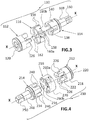
- the coupling device 110 of the figure 3 represents a variant of the device 10 Figures 1 and 2 . To facilitate comprehension, the numerical references of the elements that keep their function are preserved and increased by one hundred.
- the coupling device 110 differs from the device 10 in that the pads 126 and 140 respectively of the heads 112 and 114 do not have the same cross section, namely that the cross section of the pads 126 is rectangular while that of the pads 140 is in an angle sector of about 90 °.
- the housings 160a of the intermediate member 116 intended to receive in a complementary manner the studs 126 of the head 112 are of different shape and size of the housings 160b of the same member intended to receive in a complementary manner the studs 140 of the head 114.
- the housing 160a and only one of the housing 160b are referenced.
- the radial vanes 158 are arranged symmetrically in parallel two by two.
- the intermediate member 116 operates in the same manner as before as a continuous, electrically insulating barrier between the heads 112 and 114.
- the coupling device 210 of the figure 4 represents another variant of the device 10 Figures 1 and 2 . To facilitate comprehension, the numerical references of the elements that keep their function are preserved and increased by two hundred.
- the coupling device 210 differs from the device 110 in that the intermediate member 216 further comprises a circular and continuous external peripheral wall 270 of thickness substantially equal to that of the fins and partitions and connecting the radial end. outside of these.
- the intermediate member 216 has a cylindrical shape whose external diameter is slightly greater than that of the respective bodies 218 and 234 of the heads 212 and 214. After assembly between the bodies 218 and 234, the intermediate member 216 partially capes them view of the joint assembly.
- the invention also relates to an adapter 310, represented in the Figures 5 to 8 and adapted to be coupled to at least one tool, the adapter having a drive end adapted to be connected to a first driving tool, in particular a screwing machine, and a driven end adapted to be connected to a second tool driven, in particular a screw socket.
- the adapter 310 comprises one of the electrically insulating coupling devices 10, 110, 210 previously described, preferably the coupling device 210 (FIG. figure 4 ) which has a peripheral wall 270 ( Figures 7 and 8 ) circular and continuous.
- the coupling device 210 FIG. figure 4
- FIG. figure 4 only one of the slots 260a (shown in broken lines) and only one of the slots 260b are referenced
- the adapter 310 has a thick outer insulation coating 380 which may include one or more layers of different colors of PVC (polyvinyl chloride), which has the effect of electrically isolating the operator of the adapter.
- the coating 380 is obtained by dipping and is integral with the outer surface of the coupling device 210, except for the two ends of the device comprising the coupling means, namely the outer face 220 of the head 212 and the shaft 248 of the head 214.
- a skirt 382 axially extends externally the coating 380 around the shaft 248, the free end 384 of the skirt 382 being recessed axially relative to the male square drive profile 250.
- the inner face 386 of the skirt 382 is spaced from the shaft 248, creating a space 388 allowing an overlap of the insulating skirt 382 with another insulated tool (not shown), such as a sleeve, assembled to the male drive square 250.
- the adapter 310 which is both insulating and insulated, is used for screwing or unscrewing members maintained at a voltage less than or equal to 1000 volts AC or less than or equal to 1500 volts DC, in particular for the installation or maintenance of electric vehicle power batteries.
- the insulating coating and the intermediate member are two distinct elements.
- the outer insulating coating is integrally integrally with the intermediate member by overmolding a suitable plastic material on the heads.
- the adapter comprises two metal heads and coupling means comprising male and female drive squares. Only one of the heads can be metallic and other types of coupling are feasible.
- the users work safely in relation to the possible electric shocks and the installations on which these users intervene are preserved from any damage related to an electric arc.
- the coupling device and the corresponding tool adapter are simple, compact, and cost effective to manufacture.
Landscapes
- Engineering & Computer Science (AREA)
- Mechanical Engineering (AREA)
- General Engineering & Computer Science (AREA)
- Connector Housings Or Holding Contact Members (AREA)
- Insulating Bodies (AREA)
- Details Of Spanners, Wrenches, And Screw Drivers And Accessories (AREA)
Description
- La présente invention concerne un dispositif d'accouplement en rotation isolant électriquement comprenant une première et une deuxième têtes d'accouplement s'étendant de manière sensiblement alignée suivant un axe longitudinal, la première tête comportant au moins une partie mâle s'étendant sensiblement axialement et la deuxième tête comportant au moins une partie femelle axiale associée coopérant pour transmettre le couple de rotation ; un organe intermédiaire comportant des moyens d'isolation électrique agencés de telle manière que les parties mâle et femelle de transmission de couple sont isolées électriquement l'une par rapport à l'autre.
- Dans le domaine de l'électricité ou de l'électromécanique, il est fréquent d'utiliser des outils isolés électriquement pour intervenir sur des organes sous tension électrique. Les opérateurs mettant en oeuvre des outils isolés travaillent sur ces organes dans des conditions de sécurité satisfaisantes.
- Toutefois, les outils isolés ne préviennent pas les risques d'endommagement électrique des équipements électroniques disposés en amont de l'outil isolé par rapport aux organes sous tension électrique disposés en aval dudit outil.
- Il est connu du brevet
US-A-2,025,838 d'accoupler deux extrémités d'arbres alignés de façon élastique et isolée par l'intermédiaire d'un organe de transmission dans un matériau non métallique introduit entre deux têtes d'accouplement agissant conjointement. L'organe de transmission a pour fonction d'isoler électriquement lesdites têtes l'une par rapport à l'autre. Cependant, un tel dispositif n'est pas prévu pour supporter un champ électrique élevé et ne permet pas une protection efficace des équipements. - Il est connu de la publication de brevet
US4,927,403 d'accoupler deux arbres alignés de façon isolée par l'intermédiaire d'un organe de transmission dans un matériau non métallique introduit entre deux têtes d'accouplement agissant conjointement. - Il est connu des publications de brevet
US4,034,757 ,US4,172,369 ,US2011/0319176 etJP2006083953 - L'invention a pour but d'améliorer la protection électrique d'un dispositif d'accouplement.
- A cet effet, l'invention a pour objet un dispositif d'accouplement isolant électriquement du type précité, caractérisé en ce que l'organe intermédiaire comprend un cloisonnement isolant électriquement transversal par rapport à l'axe longitudinal et disposé selon l'intégralité du joint d'assemblage entre les première et deuxième têtes.
- Ainsi, l'invention assure une isolation sûre contre les arcs électriques et en ce que l'organe intermédiaire comprend un tronçon central s'étendant axialement suivant l'axe longitudinal et délimité par deux faces d'extrémité transversales.
- Selon d'autres caractéristiques :
- les moyens d'isolation électrique et le cloisonnement isolant électriquement transversal de l'organe intermédiaire sont d'un seul tenant ;
- les première et/ou deuxième têtes est(sont) une(des) pièce(s) usinée(s) en acier et l'organe intermédiaire est une pièce moulée en un matériau plastique de rigidité diélectrique élevée;
- La présente invention concerne également un adaptateur apte à être accouplé à au moins un outil, l'adaptateur comportant une extrémité d'entraînement apte à être reliée à un premier outil entraînant, en particulier une machine de vissage, et une extrémité entraînée apte à être reliée à un deuxième outil entraîné, en particulier une douille de vissage, caractérisé en ce qu'il comprend un dispositif d'accouplement tel que décrit précédemment.
- Selon d'autres caractéristiques :
- les premier et deuxième têtes comportent respectivement une extrémité d'entraînement à profil femelle et une extrémité entraînée à profil mâle ;
- l'adaptateur comprend, en outre, un revêtement extérieur en matériau électriquement isolant, en particulier comportant 1 ou plusieurs couches obtenue(s) par trempage ;
- La présente invention concerne aussi l'utilisation d'un adaptateur tel que décrit précédemment pour visser ou dévisser des organes maintenus sous tension électrique inférieure ou égale à 1000 volts en courant alternatif et inférieure ou égale à 1500 volts en courant continu, en particulier pour la pose ou la maintenance de batteries d'alimentation de véhicules électriques.
- L'invention et ses avantages seront mieux compris à la lecture de la description qui va suivre, donnée uniquement à titre d'exemple et faite en se référant aux dessins annexés, sur lesquels :
- Les
figures 1 et 2 sont respectivement des vues en perspective et en perspective éclatée d'un dispositif d'accouplement selon l'invention, - la
figure 3 est une vue analogue à lafigure 2 d'une première variante du dispositif selon l'invention, - la
figure 4 est une vue analogue à lafigure 2 orientée à l'inverse d'une deuxième variante du dispositif selon l'invention, - la
figure 5 est une vue en perspective d'un adaptateur comportant le dispositif d'accouplement de lafigure 4 , - la
figure 6 est une vue de côté selon la flèche VI de lafigure 5 , - la
figure 7 est une vue en coupe selon les lignes VII de lafigure 6 - la
figure 8 est une vue en coupe selon les lignes VIII de lafigure 6 . - Les termes « intérieur » et « extérieur » utilisés dans la description qui va suivre, s'entendent suivant l'orientation de l'assemblage des
figures 1 à 5 ,7 et 8 - Les
figures 1 et 2 représentent un dispositif d'accouplement en rotation 10 destiné à accoupler, dans une position de travail, une machine menante et un objet mené (non représentés). - Le dispositif 10 s'étend suivant un axe longitudinal X-X. Il comprend une première tête 12 définissant une partie entraînante en rotation par rapport à l'axe X-X, et une seconde tête 14 définissant une partie entraînée en rotation par rapport au même axe, les têtes étant sensiblement alignées suivant l'axe X-X. Chacune des têtes 12 ou 14 est métallique et fabriquée, de préférence d'une seule pièce par usinage, en acier.
- Le dispositif 10 comprend également un organe intermédiaire 16 qui est disposé assemblé entre les têtes 12 et 14. Il a pour but de transmettre le couple de la première tête 12 à la deuxième tête 14, et d'isoler électriquement les dites têtes l'une par rapport à l'autre. L'organe intermédiaire 16 est non métallique et moulé, de préférence d'un seul tenant, en matière plastique dont la caractéristique de rigidité diélectrique est élevée pour obtenir une isolation électrique efficace, en particulier en PETP (polyéthylène téréphtalate) ou en PEEK (polyétheréthercétone).
- La tête entraînante 12 comporte un corps sensiblement cylindrique 18 délimité par une première face 20 extérieure et une deuxième face 22 intérieure (
figure 2 ), toutes deux sensiblement perpendiculaires à l'axe X-X. - La face extérieure 20 comprend un moyen d'accouplement 24 sous forme d'une cavité comportant un profil femelle de section transversale carrée.
- Au moins un plot 26 (
figure 2 ), de préférence une pluralité de plots, en particulier quatre plots 26 (figure 2 ), est (sont) disposé (s) en saillie axiale à partir de la face intérieure 22 suivant l'axe X-X. Les plots 26 de lafigure 2 sont identiques et ont la forme d'un élément de tore de section rectangulaire et présentent une section transversale par rapport à l'axe X-X en forme de secteur d'angle d'environ 45°. Leurs dimensions axiales sont égales. Les plots 26 sont répartis de la manière équidistante angulairement par rapport à l'axe X-X. Ainsi, un plot 26 est adjacent à un évidement 28 également en forme de secteur d'angle identique mais de dimension transversale supérieure à celle du plot. Pour la clarté de lafigure 2 , un seul des évidements 28 est référencé. Chaque plot 26 comprend principalement deux faces latérales 30 radiales et une face d'extrémité libre 32 transversale. - La tête entraînée 14 comporte également un corps sensiblement cylindrique 34 délimité par une première face 36 extérieure et une deuxième face 38 intérieure (
figure 2 ), toutes deux sensiblement perpendiculaires à l'axe X-X. - Au moins un plot 40 (
figure 2 ), de préférence une pluralité de plots identique en nombre à celui des plots 26 de la tête 12, en particulier quatre plots 40 (figure 2 ), est (sont) disposé (s) en saillie axiale à partir de la face intérieure 38 suivant l'axe X-X. Les plots 40 de la tête 14 sont sensiblement identiques aux plots 26 de la tête 12 et sont répartis de la même manière par rapport à l'axe X-X. Leurs dimensions axiales sont égales. Un plot 40 est adjacent à un évidement 42 en forme générale de secteur d'angle identique mais de dimension transversale supérieure à celle du plot. Pour la clarté de lafigure 2 , un seul des évidements 42 est référencé. Chaque plot 40 comprend principalement deux faces latérales 44 radiales et une face d'extrémité libre 46 transversale. - Un arbre cylindrique 48 s'étend axialement en saillie par rapport à la face 36 extérieure de la tête 14 suivant l'axe X-X. L'extrémité libre de l'arbre 48 comporte un moyen d'accouplement 50 sous forme d'un profil mâle de section transversale carrée.
- L'organe intermédiaire 16 de transmission comporte d'une part, des formes complémentaires adaptées pour coopérer, au jeu près, avec le ou chaque plot 26 et le ou chaque évidement 28 de la tête 12 et, d'autre part, des formes complémentaires adaptées pour coopérer, également au jeu près, avec le ou chaque plot 40 et le ou chaque évidement 42 de la tête 14.
- Pour cela, l'organe intermédiaire 16 comprend un tronçon central 52 s'étendant axialement suivant l'axe X-X et délimité par deux faces d'extrémité 54 et 56 transversales.
- Au moins deux ailettes 58 (
figure 2 ), de préférence une pluralité d'ailettes en nombre égal au double de celui des plots, en particulier huit ailettes 58 (sur lafigure 2 , seules quatre ailettes sont visibles et référencées), s'étendent à partir du tronçon central 52 radialement par rapport à l'axe X-X et axialement depuis la face d'extrémité 54 jusqu'à la face d'extrémité 56. Les ailettes 58 sont réparties de manière équidistante angulairement par rapport à l'axe X-X. - L'organe intermédiaire 16 comporte au moins un logement 60 de réception qui sépare deux ailettes adjacentes 58, de préférence une pluralité de logements en nombre égal au double de celui des plots, en particulier huit logements 60 (
figure 2 ). Pour la clarté de lafigure 2 , un seul des logements 60 est référencé. - Les première et deuxième têtes 12 et 14 sont agencées de telle manière que le ou chaque plot d'un des premier ou deuxième corps 18 et 34 est reçu, par emboîtement axial et avec jeu, dans un évidement correspondant de l'autre desdits premier ou deuxième corps auquel il est associé, les ailettes 58 de l'organe intermédiaire 16 étant interposées entre le ou chaque plot 26 du premier corps 18 et le ou chaque plot 40 adjacent du deuxième corps 34 de façon à ce que les têtes 12 et 14 sont isolées électriquement l'une par rapport à l'autre.
- La structure du dispositif d'accouplement 10 est telle que les logements 60 de l'organe intermédiaire 16 sont propres à recevoir en alternance le ou un des plots 26 de la tête entraînante 12 et le ou un des plots 40 de la tête entraînée 14 par emboitement axial.
- De cette manière, chaque ailette 58 maintient à distance les faces latérales 30 et 44 respectives des plots 26 et 40 adjacents, en isolant électriquement lesdites faces latérales les unes par rapport aux autres.
- La dimension axiale de l'organe intermédiaire 16 est telle, qu'après emboitement axial de l'organe 16 entre les deux têtes 12 et 14, la face d'extrémité libre 32 de chaque plot 26 de la tête 12 est à distance de la face intérieure 38 du corps 34 de la tête 14 correspondant au fond de l'évidement 42 associé, et telle que la face d'extrémité libre 46 de chaque plot 40 de la tête 14 est également maintenue distante de la face intérieure 22 du corps 18 de la tête 12 correspondant au fond de l'évidement 28 associé.
- L'organe intermédiaire 16 comprend un cloisonnement 62 isolant électriquement transversal par rapport à l'axe X-X et disposé selon l'intégralité du joint d'assemblage entre les première et deuxième têtes 12 et 14.
- Pour cela, l'organe intermédiaire 16 comporte au moins une cloison 62, de préférence une pluralité de cloisons en nombre égal à celui des ailettes, en particulier huit cloisons 62 (sur la
figure 2 , seules trois cloisons 62 sont visibles et référencées) disposées transversalement par rapport à l'axe X-X. Elles occupent les espaces entre, d'une part, le ou les plot(s) 26 et le fond de l'évidement 42 associé et, d'autre part, le ou les plot(s) 40 et le fond de l'évidement 28 associé. Chaque cloison 62 s'étend depuis le tronçon central 52 jusqu'à l'extrémité libre d'une ailette 58 et relie deux ailettes 58 adjacentes. Les cloisons 62 sont disposées en alternance dans le prolongement de chacune des faces d'extrémité 54 et 56 du tronçon 52. En d'autres termes, pour deux logements 60 voisins, l'un est ouvert sur la face d'extrémité 54 de l'organe intermédiaire 16, et l'autre sur la face d'extrémité 56 opposée. - L'épaisseur des ailettes 58 et celle des cloisons 62 sont sensiblement égales.
- L'organe intermédiaire 16 est d'un seul tenant, compact et a pour fonction d'être une barrière continue et électriquement isolante entre les têtes 12 et 14. De plus, les extrémités libres des ailettes 58 et cloisons 62 sont, au joint d'assemblage, en relief (
figure 1 ) par rapport à la surface extérieure des têtes 12 et 14, ce qui assure une isolation efficace contre les arcs électriques. - Le dispositif d'accouplement 110 de la
figure 3 représente une variante du dispositif 10 desfigures 1 et 2 . Pour faciliter la compréhension, les références numériques des éléments qui gardent leur fonction sont conservées et augmentées de cent. - Le dispositif d'accouplement 110 diffère du dispositif 10 en ce que les plots 126 et 140 respectifs des têtes 112 et 114 ne présentent pas la même section transversale, à savoir que la section transversale des plots 126 est rectangulaire tandis que celle des plots 140 est en secteur d'angle d'environ 90°. Il en résulte que les logements 160a de l'organe intermédiaire 116 destinés à recevoir de façon complémentaire les plots 126 de la tête 112 sont de forme et de dimension différentes des logements 160b du même organe destinés à recevoir de façon complémentaire les plots 140 de la tête 114. Pour la clarté de la
figure 3 , un seul des logements 160a et un seul des logements 160b sont référencés. - Les ailettes radiales 158 sont disposées symétriquement en parallèle deux par deux. L'organe intermédiaire 116 fonctionne de la même manière que précédemment comme une barrière continue, électriquement isolante entre les têtes 112 et 114.
- Le dispositif d'accouplement 210 de la
figure 4 représente une autre variante du dispositif 10 desfigures 1 et 2 . Pour faciliter la compréhension, les références numériques des éléments qui gardent leur fonction sont conservées et augmentées de deux cents. - Le dispositif d'accouplement 210 diffère du dispositif 110 en ce que l'organe intermédiaire 216 comprend, en outre, une paroi périphérique 270 extérieure circulaire et continue, d'épaisseur sensiblement égale à celles des ailettes et des cloisons et reliant l'extrémité radiale extérieure de ces dernières. L'organe intermédiaire 216 présente une forme cylindrique dont le diamètre extérieur est légèrement supérieur à celui des corps respectifs 218 et 234 des têtes 212 et 214. Après assemblage entre les corps 218 et 234, l'organe intermédiaire 216 coiffe partiellement celles-ci en regard du joint d'assemblage.
- L'invention concerne également un adaptateur 310, représenté dans les
figures 5 à 8 , et apte à être accouplé à au moins un outil, l'adaptateur comportant une extrémité d'entraînement apte à être reliée à un premier outil entraînant, en particulier une machine de vissage, et une extrémité entraînée apte à être reliée à un deuxième outil entraîné, en particulier une douille de vissage. L'adaptateur 310 comprend l'un des dispositifs 10, 110, 210 d'accouplement isolants électriquement décrits précédemment, de préférence le dispositif d'accouplement 210 (figure 4 ) qui présente une paroi périphérique 270 (figures 7 et 8 ) circulaire et continue. Pour la clarté de lafigure 4 , un seul des logements 260a (représenté en traits discontinus) et un seul des logements 260b sont référencés - L'adaptateur 310 comporte un revêtement isolant 380 extérieur épais pouvant comporter une ou plusieurs couches de différentes couleurs en PVC (polychlorure de vinyle), ce qui a pour effet d'isoler électriquement l'opérateur de l'adaptateur. Le revêtement 380 est obtenu par trempage et il est solidaire de la superficie extérieure du dispositif d'accouplement 210, à l'exception des deux extrémités du dispositif comportant les moyens d'accouplement, à savoir la face extérieure 220 de la tête 212 et l'arbre 248 de la tête 214. Une jupe 382 prolonge axialement extérieurement le revêtement 380 autour de l'arbre 248, l'extrémité libre 384 de la jupe 382 étant en retrait axial par rapport au profil carré d'entraînement mâle 250. La face intérieure 386 de la jupe 382 est distante de l'arbre 248, créant un espace 388 permettant un chevauchement de la jupe isolante 382 avec un autre outil isolé (non représenté), tel qu'une douille, assemblé au carré d'entraînement mâle 250.
- L'adaptateur 310, qui est à la fois isolant et isolé, est utilisé pour visser ou dévisser des organes maintenus sous une tension électrique inférieure ou égale à 1000 volts en courant alternatif ou inférieure ou égale à 1500 volts en courant continu, en particulier pour la pose ou la maintenance de batteries d'alimentation de véhicules électriques.
- Dans le mode de réalisation décrit précédemment, le revêtement isolant et l'organe intermédiaire sont deux éléments distincts. Dans une variante non représentée, le revêtement isolant extérieur est d'un seul tenant venu de matière avec l'organe intermédiaire par surmoulage d'un matériau plastique approprié sur les têtes.
- Dans la description précédente, l'adaptateur comprend deux têtes métalliques et des moyens d'accouplement comportant des carrés d'entraînement mâle et femelle. Une seule des têtes peut être métallique et d'autres types d'accouplement sont réalisables.
- Grâce à l'invention, les utilisateurs travaillent en sécurité par rapport aux éventuels chocs électriques et les installations sur lesquelles ces utilisateurs interviennent sont préservées d'éventuels endommagements liés à un arc électrique. De plus, le dispositif d'accouplement et l'adaptateur pour outil correspondant sont simples, compacts, et d'un coût de fabrication économique.
Claims (6)
- Dispositif d'accouplement en rotation (10 ; 110 ; 210) isolant électriquement comprenant une première (12 ; 112 ; 212) et une deuxième (14 ; 114 ; 214) têtes d'accouplement s'étendant de manière sensiblement alignée suivant un axe longitudinal (X-X), la première tête comportant au moins une partie mâle (26 ; 126 ; 226) s'étendant sensiblement axialement et la deuxième tête comportant au moins une partie femelle (42 ; 142 ; 242) axiale associée coopérant pour transmettre le couple de rotation, les partie mâle et femelle étant adaptées pour former un joint d'assemblage entre les première (12 ; 112 ; 212) et deuxième (14 ; 1 14 ; 214) têtes ; un organe intermédiaire (16 ; 116 ; 216) comportant des moyens d'isolation électrique (52, 54, 56, 58) agencés de telle manière que les parties mâle (26 ; 126 ; 226) et femelle (42 ; 142 ; 242) de transmission de couple sont isolées électriquement l'une par rapport à l'autre, caractérisé en ce que l'organe intermédiaire (16 ; 1 16 ; 216) comprend un cloisonnement isolant électriquement transversal (62 ; 162 ; 262) par rapport à l'axe longitudinal (X-X) et disposé selon l'intégralité du joint d'assemblage entre les première (12 ; 112 ; 212) et deuxième (14 ; 1 14 ; 214) têtes et en ce que l'organe intermédiaire comprend un tronçon central (52) s'étendant axialement suivant l'axe longitudinal (X-X) et délimité par deux faces d'extrémité transversales (54, 56), en ce qu'au moins une des première (12 ; 1 12 ; 212) et deuxième (14 ; 114 ; 214) têtes est une pièce usinée en acier, et en ce que l'organe intermédiaire (16 ; 116 ; 216) est une pièce moulée en un matériau plastique de rigidité diélectrique élevée.
- Dispositif selon la revendication 1, caractérisée en ce que les moyens d'isolation électrique (52, 54, 56, 58) et le cloisonnement isolant électriquement transversal (62 ; 162 ; 262) de l'organe intermédiaire (16 ; 1 16 ; 216) sont d'un seul tenant.
- Adaptateur (310) apte à être accouplé à au moins un outil, l'adaptateur comportant une extrémité d'entraînement (24 ; 124 ; 224) apte à être reliée à un premier outil entraînant, en particulier une machine de vissage, et une extrémité entraînée (50 ; 150 250) apte à être reliée à un deuxième outil entraîné, en particulier une douille de vissage, caractérisé en ce qu'il comprend un dispositif d'accouplement (10 ; 110 ;210) selon l'une quelconque des revendications 1 à 2.
- Adaptateur selon la revendication 3, caractérisée en ce que les première (12 ; 1 12 ; 212) et deuxième (14 ; 1 14 ; 214) têtes comportent respectivement une extrémité d'entraînement à profil femelle (24 ; 124 ; 224) et une extrémité entraînée à profil mâle (50 ; 150 250).
- Adaptateur selon l'une quelconque des revendications 3 à 4, caractérisée en ce qu'il comprend, en outre, un revêtement (380) extérieur en matériau électriquement isolant, en particulier comportant 1 ou plusieurs couches obtenue(s) par trempage.
- Utilisation d'un adaptateur (310) selon l'une quelconque des revendications 3 à 5 pour visser ou dévisser des organes maintenus sous une tension électrique inférieure ou égale à 1000 volts en courant alternatif et inférieure ou égale à 1500 volts en courant continu, en particulier pour la pose ou la maintenance de batteries d'alimentation de véhicules électriques.
Applications Claiming Priority (2)
| Application Number | Priority Date | Filing Date | Title |
|---|---|---|---|
| FR1100388A FR2971310A3 (fr) | 2011-02-08 | 2011-02-08 | Dispositif d'accouplement en rotation isolant electriquement ameliore, et adaptateur pour outil comportant un tel dispositif |
| PCT/EP2012/051235 WO2012107299A1 (fr) | 2011-02-08 | 2012-01-26 | Dispositif d'accouplement en rotation isolant électriquement amélioré, et adaptateur pour outil comportant un tel dispositif |
Publications (2)
| Publication Number | Publication Date |
|---|---|
| EP2673518A1 EP2673518A1 (fr) | 2013-12-18 |
| EP2673518B1 true EP2673518B1 (fr) | 2018-02-28 |
Family
ID=45531874
Family Applications (1)
| Application Number | Title | Priority Date | Filing Date |
|---|---|---|---|
| EP12701252.4A Active EP2673518B1 (fr) | 2011-02-08 | 2012-01-26 | Dispositif d'accouplement en rotation isolant électriquement amélioré, et adaptateur pour outil comportant un tel dispositif |
Country Status (5)
| Country | Link |
|---|---|
| US (1) | US20130341069A1 (fr) |
| EP (1) | EP2673518B1 (fr) |
| CN (1) | CN103380307B (fr) |
| FR (1) | FR2971310A3 (fr) |
| WO (1) | WO2012107299A1 (fr) |
Families Citing this family (24)
| Publication number | Priority date | Publication date | Assignee | Title |
|---|---|---|---|---|
| WO2016177394A1 (fr) * | 2015-05-04 | 2016-11-10 | Volvo Truck Corporation | Accouplement d'arbres |
| EP3389927B1 (fr) | 2015-12-18 | 2020-02-05 | Apex Brands, Inc. | Dispositif d'entraînement d'éléments de fixation électriquement isolé |
| WO2018070485A1 (fr) * | 2016-10-13 | 2018-04-19 | 日本精工株式会社 | Joint de transmission de couple et dispositif de servodirection électrique |
| WO2018121819A1 (fr) | 2016-12-29 | 2018-07-05 | Vestas Wind Systems A/S | Joint d'arbre isolé |
| ES2989416T3 (es) | 2017-05-02 | 2024-11-26 | Apex Brands Inc | Acoplamiento aislado eléctricamente |
| CN110076719A (zh) * | 2018-01-26 | 2019-08-02 | 徐博宁 | 扭矩输入端与扭矩输出端电气绝缘的连接与扭矩传递装置 |
| CA3100287C (fr) * | 2018-06-26 | 2023-02-21 | Apex Brands, Inc. | Adaptateur isole electriquement |
| EP3941684A4 (fr) | 2019-04-03 | 2022-11-23 | Apex Brands, Inc. | Outil isolé électriquement avec revêtement à sécurité intégrée |
| CN113646135B (zh) | 2019-04-04 | 2023-02-03 | 艾沛克斯品牌公司 | 具有非导电扭矩传递部件的电隔离工具 |
| US20200332920A1 (en) * | 2019-04-22 | 2020-10-22 | MKS Insturments, Inc | Heated Throttle Valve Apparatus and Methods of Use and Manufacture |
| EP3940256A1 (fr) * | 2020-07-17 | 2022-01-19 | Johannes Lübbering GmbH | Accouplement pour la transmission, isolée électriquement, de couple et l'utilisation de l'accouplement avec un outillage ou dans une chaîne cinématique |
| USD1049803S1 (en) * | 2020-10-26 | 2024-11-05 | Kody J. Ketterling | Driver for rotary sod cutting tool |
| EP4043763A1 (fr) * | 2021-02-15 | 2022-08-17 | Goodrich Corporation | Ensemble d'entraînement d'articulation souple |
| TWI802232B (zh) * | 2021-03-04 | 2023-05-11 | 優鋼機械股份有限公司 | 手工具 |
| DE202021101677U1 (de) * | 2021-03-30 | 2022-07-12 | Gustav Klauke Gmbh | Adapterteil zur Anordnung zwischen einer Antriebseinrichtung und einem Werkzeug |
| EP4112979B1 (fr) * | 2021-06-29 | 2024-12-25 | Goodrich Corporation | Ensemble d'entraînement d'articulation souple |
| GB2609430A (en) * | 2021-07-30 | 2023-02-08 | Atlas Copco Airpower Nv | Shaft assembly |
| USD1017031S1 (en) * | 2021-09-10 | 2024-03-05 | Aegis Spine, Inc. | Medical device adapter |
| EP4148304B1 (fr) | 2021-09-13 | 2025-03-12 | Goodrich Corporation | Ensemble d'entraînement d'articulation souple |
| EP4148305B1 (fr) | 2021-09-13 | 2025-03-12 | Goodrich Corporation | Ensemble d'entraînement d'articulation souple |
| USD1003129S1 (en) * | 2021-12-05 | 2023-10-31 | Four Cam Engineering LLC | Knob tool |
| EP4242501A1 (fr) | 2022-03-11 | 2023-09-13 | Goodrich Corporation | Ensemble entraînement d'articulation souple |
| FR3133501A1 (fr) * | 2022-03-14 | 2023-09-15 | Alstom Holdings | Moteur électrique et procédé de production correspondant |
| TWI826035B (zh) * | 2022-10-11 | 2023-12-11 | 英發企業股份有限公司 | 防觸電的手工具 |
Citations (2)
| Publication number | Priority date | Publication date | Assignee | Title |
|---|---|---|---|---|
| FR2135386A1 (fr) * | 1971-05-03 | 1972-12-22 | Busseau Suzanne | |
| EP1116555A2 (fr) * | 1999-09-07 | 2001-07-18 | Snap-On Tools Company | Tournevis à cliquet composite |
Family Cites Families (14)
| Publication number | Priority date | Publication date | Assignee | Title |
|---|---|---|---|---|
| US1548629A (en) * | 1923-10-01 | 1925-08-04 | William C Durant | Cushion coupling |
| US2025838A (en) * | 1928-10-18 | 1935-12-31 | Louis Ricefield | Insulating flexible shaft coupling |
| US2301660A (en) * | 1941-06-21 | 1942-11-10 | Ricefield Louis | Coupling |
| LU65497A1 (fr) * | 1972-06-12 | 1972-10-23 | ||
| US3859821A (en) * | 1972-06-22 | 1975-01-14 | Vanmark Corp | Flexible coupling |
| US4034575A (en) * | 1973-04-11 | 1977-07-12 | Harald Barth | Annular elastic component for flexible jaw coupling |
| US3873863A (en) * | 1974-02-25 | 1975-03-25 | Singer Co | Double insulated electrically powered hand tool and coupler therefor |
| US4172369A (en) * | 1978-03-13 | 1979-10-30 | Hayes Charles J | Flexible coupling |
| DE3010127A1 (de) * | 1980-03-15 | 1981-09-24 | Fa. Carl Freudenberg, 6940 Weinheim | Drehelastische kupplung |
| US4927403A (en) * | 1987-02-24 | 1990-05-22 | Pate Sr Kenneth D | High voltage insulative shaft coupler |
| JP2515645Y2 (ja) * | 1989-11-21 | 1996-10-30 | アスモ 株式会社 | 減速機付モ−タ |
| JP4320627B2 (ja) * | 2004-09-16 | 2009-08-26 | Nok株式会社 | トルク伝達装置 |
| CN102265060A (zh) * | 2008-11-26 | 2011-11-30 | 南德盘形接轴节工厂股份有限公司 | 扭矩减振传递装置 |
| JP5483466B2 (ja) * | 2011-04-15 | 2014-05-07 | アサ電子工業株式会社 | カップリング |
-
2011
- 2011-02-08 FR FR1100388A patent/FR2971310A3/fr active Pending
-
2012
- 2012-01-26 EP EP12701252.4A patent/EP2673518B1/fr active Active
- 2012-01-26 CN CN201280007919.2A patent/CN103380307B/zh not_active Expired - Fee Related
- 2012-01-26 US US13/984,054 patent/US20130341069A1/en not_active Abandoned
- 2012-01-26 WO PCT/EP2012/051235 patent/WO2012107299A1/fr not_active Ceased
Patent Citations (2)
| Publication number | Priority date | Publication date | Assignee | Title |
|---|---|---|---|---|
| FR2135386A1 (fr) * | 1971-05-03 | 1972-12-22 | Busseau Suzanne | |
| EP1116555A2 (fr) * | 1999-09-07 | 2001-07-18 | Snap-On Tools Company | Tournevis à cliquet composite |
Also Published As
| Publication number | Publication date |
|---|---|
| WO2012107299A1 (fr) | 2012-08-16 |
| US20130341069A1 (en) | 2013-12-26 |
| EP2673518A1 (fr) | 2013-12-18 |
| FR2971310A3 (fr) | 2012-08-10 |
| CN103380307A (zh) | 2013-10-30 |
| CN103380307B (zh) | 2017-03-22 |
Similar Documents
| Publication | Publication Date | Title |
|---|---|---|
| WO2012107299A1 (fr) | Dispositif d'accouplement en rotation isolant électriquement amélioré, et adaptateur pour outil comportant un tel dispositif | |
| WO2008102470A1 (fr) | Compresseur électrique | |
| WO2018204468A1 (fr) | Couplage électriquement isolé | |
| EP2477278A1 (fr) | Manchon pour connecteur électrique et son procédé d'assemblage | |
| JP2009545109A (ja) | 水中ポンプに連結されるケーブル連結部 | |
| FR3141012A1 (fr) | Ensemble de brosse de mise à la terre | |
| EP3084214B1 (fr) | Dispositif de fixation et raccordement électrique d'un compresseur hermétique | |
| WO2008110725A2 (fr) | Module conducteur de courant et alternateur | |
| EP3097634B1 (fr) | Dispositif isolant pour collecteur de machine electrique, collecteur et alternateur correspondants | |
| FR3099303A1 (fr) | Contact de puissance femelle | |
| EP2677602B1 (fr) | Connecteur de raccordement pour au moins deux câbles électriques | |
| EP3079230B1 (fr) | Pince a souder et son moteur electrique | |
| EP3599669B1 (fr) | Borne électrique femelle et procédé de montage d'une borne électrique femelle | |
| EP3465834B1 (fr) | Connecteur pour véhicule automobile comportant un contact femelle qui comporte une douille avec au moins une languette flexible | |
| EP3404773B1 (fr) | Dispositif de maintien d'au moins un tuyau conducteur electrique sur une structure conductrice electrique | |
| EP3320604A1 (fr) | Machine électrique tournante munie d'un moyen de réglage de la position angulaire de l'arbre | |
| EP3320603A1 (fr) | Machine électrique tournante a refroidissement optimise | |
| EP3320602B1 (fr) | Machine electrique tournante munie d'un reservoir de lubrifiant pour la lubrification d'un roulement et le refroidissement de la machine | |
| EP3876363B1 (fr) | Accessoire de prise électrique rotatif | |
| EP2874242B1 (fr) | Connecteur électrique modulaire, formant un connecteur mobile de prise électrique | |
| JP2019531992A5 (fr) | ||
| WO2017134376A1 (fr) | Ensemble poulie pour une machine electrique tournante | |
| EP4680876A1 (fr) | Agencement d'un arbre et d'un carter | |
| BE637115A (fr) | ||
| FR3152667A1 (fr) | Ensemble de brosse de mise à la terre |
Legal Events
| Date | Code | Title | Description |
|---|---|---|---|
| PUAI | Public reference made under article 153(3) epc to a published international application that has entered the european phase |
Free format text: ORIGINAL CODE: 0009012 |
|
| 17P | Request for examination filed |
Effective date: 20130906 |
|
| AK | Designated contracting states |
Kind code of ref document: A1 Designated state(s): AL AT BE BG CH CY CZ DE DK EE ES FI FR GB GR HR HU IE IS IT LI LT LU LV MC MK MT NL NO PL PT RO RS SE SI SK SM TR |
|
| DAX | Request for extension of the european patent (deleted) | ||
| 17Q | First examination report despatched |
Effective date: 20160324 |
|
| STAA | Information on the status of an ep patent application or granted ep patent |
Free format text: STATUS: EXAMINATION IS IN PROGRESS |
|
| GRAP | Despatch of communication of intention to grant a patent |
Free format text: ORIGINAL CODE: EPIDOSNIGR1 |
|
| STAA | Information on the status of an ep patent application or granted ep patent |
Free format text: STATUS: GRANT OF PATENT IS INTENDED |
|
| INTG | Intention to grant announced |
Effective date: 20171122 |
|
| GRAS | Grant fee paid |
Free format text: ORIGINAL CODE: EPIDOSNIGR3 |
|
| GRAA | (expected) grant |
Free format text: ORIGINAL CODE: 0009210 |
|
| STAA | Information on the status of an ep patent application or granted ep patent |
Free format text: STATUS: THE PATENT HAS BEEN GRANTED |
|
| AK | Designated contracting states |
Kind code of ref document: B1 Designated state(s): AL AT BE BG CH CY CZ DE DK EE ES FI FR GB GR HR HU IE IS IT LI LT LU LV MC MK MT NL NO PL PT RO RS SE SI SK SM TR |
|
| REG | Reference to a national code |
Ref country code: GB Ref legal event code: FG4D Free format text: NOT ENGLISH Ref country code: CH Ref legal event code: EP |
|
| REG | Reference to a national code |
Ref country code: AT Ref legal event code: REF Ref document number: 974505 Country of ref document: AT Kind code of ref document: T Effective date: 20180315 |
|
| REG | Reference to a national code |
Ref country code: IE Ref legal event code: FG4D Free format text: LANGUAGE OF EP DOCUMENT: FRENCH |
|
| REG | Reference to a national code |
Ref country code: DE Ref legal event code: R096 Ref document number: 602012043321 Country of ref document: DE |
|
| REG | Reference to a national code |
Ref country code: NL Ref legal event code: MP Effective date: 20180228 |
|
| REG | Reference to a national code |
Ref country code: LT Ref legal event code: MG4D |
|
| REG | Reference to a national code |
Ref country code: AT Ref legal event code: MK05 Ref document number: 974505 Country of ref document: AT Kind code of ref document: T Effective date: 20180228 |
|
| PG25 | Lapsed in a contracting state [announced via postgrant information from national office to epo] |
Ref country code: FI Free format text: LAPSE BECAUSE OF FAILURE TO SUBMIT A TRANSLATION OF THE DESCRIPTION OR TO PAY THE FEE WITHIN THE PRESCRIBED TIME-LIMIT Effective date: 20180228 Ref country code: CY Free format text: LAPSE BECAUSE OF FAILURE TO SUBMIT A TRANSLATION OF THE DESCRIPTION OR TO PAY THE FEE WITHIN THE PRESCRIBED TIME-LIMIT Effective date: 20180228 Ref country code: NL Free format text: LAPSE BECAUSE OF FAILURE TO SUBMIT A TRANSLATION OF THE DESCRIPTION OR TO PAY THE FEE WITHIN THE PRESCRIBED TIME-LIMIT Effective date: 20180228 Ref country code: ES Free format text: LAPSE BECAUSE OF FAILURE TO SUBMIT A TRANSLATION OF THE DESCRIPTION OR TO PAY THE FEE WITHIN THE PRESCRIBED TIME-LIMIT Effective date: 20180228 Ref country code: LT Free format text: LAPSE BECAUSE OF FAILURE TO SUBMIT A TRANSLATION OF THE DESCRIPTION OR TO PAY THE FEE WITHIN THE PRESCRIBED TIME-LIMIT Effective date: 20180228 Ref country code: HR Free format text: LAPSE BECAUSE OF FAILURE TO SUBMIT A TRANSLATION OF THE DESCRIPTION OR TO PAY THE FEE WITHIN THE PRESCRIBED TIME-LIMIT Effective date: 20180228 Ref country code: NO Free format text: LAPSE BECAUSE OF FAILURE TO SUBMIT A TRANSLATION OF THE DESCRIPTION OR TO PAY THE FEE WITHIN THE PRESCRIBED TIME-LIMIT Effective date: 20180528 |
|
| PG25 | Lapsed in a contracting state [announced via postgrant information from national office to epo] |
Ref country code: GR Free format text: LAPSE BECAUSE OF FAILURE TO SUBMIT A TRANSLATION OF THE DESCRIPTION OR TO PAY THE FEE WITHIN THE PRESCRIBED TIME-LIMIT Effective date: 20180529 Ref country code: BG Free format text: LAPSE BECAUSE OF FAILURE TO SUBMIT A TRANSLATION OF THE DESCRIPTION OR TO PAY THE FEE WITHIN THE PRESCRIBED TIME-LIMIT Effective date: 20180528 Ref country code: RS Free format text: LAPSE BECAUSE OF FAILURE TO SUBMIT A TRANSLATION OF THE DESCRIPTION OR TO PAY THE FEE WITHIN THE PRESCRIBED TIME-LIMIT Effective date: 20180228 Ref country code: AT Free format text: LAPSE BECAUSE OF FAILURE TO SUBMIT A TRANSLATION OF THE DESCRIPTION OR TO PAY THE FEE WITHIN THE PRESCRIBED TIME-LIMIT Effective date: 20180228 Ref country code: SE Free format text: LAPSE BECAUSE OF FAILURE TO SUBMIT A TRANSLATION OF THE DESCRIPTION OR TO PAY THE FEE WITHIN THE PRESCRIBED TIME-LIMIT Effective date: 20180228 Ref country code: LV Free format text: LAPSE BECAUSE OF FAILURE TO SUBMIT A TRANSLATION OF THE DESCRIPTION OR TO PAY THE FEE WITHIN THE PRESCRIBED TIME-LIMIT Effective date: 20180228 |
|
| PG25 | Lapsed in a contracting state [announced via postgrant information from national office to epo] |
Ref country code: MT Free format text: LAPSE BECAUSE OF FAILURE TO SUBMIT A TRANSLATION OF THE DESCRIPTION OR TO PAY THE FEE WITHIN THE PRESCRIBED TIME-LIMIT Effective date: 20180228 |
|
| PG25 | Lapsed in a contracting state [announced via postgrant information from national office to epo] |
Ref country code: EE Free format text: LAPSE BECAUSE OF FAILURE TO SUBMIT A TRANSLATION OF THE DESCRIPTION OR TO PAY THE FEE WITHIN THE PRESCRIBED TIME-LIMIT Effective date: 20180228 Ref country code: PL Free format text: LAPSE BECAUSE OF FAILURE TO SUBMIT A TRANSLATION OF THE DESCRIPTION OR TO PAY THE FEE WITHIN THE PRESCRIBED TIME-LIMIT Effective date: 20180228 Ref country code: RO Free format text: LAPSE BECAUSE OF FAILURE TO SUBMIT A TRANSLATION OF THE DESCRIPTION OR TO PAY THE FEE WITHIN THE PRESCRIBED TIME-LIMIT Effective date: 20180228 Ref country code: AL Free format text: LAPSE BECAUSE OF FAILURE TO SUBMIT A TRANSLATION OF THE DESCRIPTION OR TO PAY THE FEE WITHIN THE PRESCRIBED TIME-LIMIT Effective date: 20180228 |
|
| REG | Reference to a national code |
Ref country code: DE Ref legal event code: R097 Ref document number: 602012043321 Country of ref document: DE |
|
| PG25 | Lapsed in a contracting state [announced via postgrant information from national office to epo] |
Ref country code: CZ Free format text: LAPSE BECAUSE OF FAILURE TO SUBMIT A TRANSLATION OF THE DESCRIPTION OR TO PAY THE FEE WITHIN THE PRESCRIBED TIME-LIMIT Effective date: 20180228 Ref country code: SK Free format text: LAPSE BECAUSE OF FAILURE TO SUBMIT A TRANSLATION OF THE DESCRIPTION OR TO PAY THE FEE WITHIN THE PRESCRIBED TIME-LIMIT Effective date: 20180228 Ref country code: DK Free format text: LAPSE BECAUSE OF FAILURE TO SUBMIT A TRANSLATION OF THE DESCRIPTION OR TO PAY THE FEE WITHIN THE PRESCRIBED TIME-LIMIT Effective date: 20180228 Ref country code: SM Free format text: LAPSE BECAUSE OF FAILURE TO SUBMIT A TRANSLATION OF THE DESCRIPTION OR TO PAY THE FEE WITHIN THE PRESCRIBED TIME-LIMIT Effective date: 20180228 |
|
| PLBE | No opposition filed within time limit |
Free format text: ORIGINAL CODE: 0009261 |
|
| STAA | Information on the status of an ep patent application or granted ep patent |
Free format text: STATUS: NO OPPOSITION FILED WITHIN TIME LIMIT |
|
| 26N | No opposition filed |
Effective date: 20181129 |
|
| PG25 | Lapsed in a contracting state [announced via postgrant information from national office to epo] |
Ref country code: SI Free format text: LAPSE BECAUSE OF FAILURE TO SUBMIT A TRANSLATION OF THE DESCRIPTION OR TO PAY THE FEE WITHIN THE PRESCRIBED TIME-LIMIT Effective date: 20180228 Ref country code: IT Free format text: LAPSE BECAUSE OF FAILURE TO SUBMIT A TRANSLATION OF THE DESCRIPTION OR TO PAY THE FEE WITHIN THE PRESCRIBED TIME-LIMIT Effective date: 20180228 |
|
| PGFP | Annual fee paid to national office [announced via postgrant information from national office to epo] |
Ref country code: FR Payment date: 20181213 Year of fee payment: 8 |
|
| PG25 | Lapsed in a contracting state [announced via postgrant information from national office to epo] |
Ref country code: MC Free format text: LAPSE BECAUSE OF FAILURE TO SUBMIT A TRANSLATION OF THE DESCRIPTION OR TO PAY THE FEE WITHIN THE PRESCRIBED TIME-LIMIT Effective date: 20180228 |
|
| REG | Reference to a national code |
Ref country code: CH Ref legal event code: PL |
|
| PG25 | Lapsed in a contracting state [announced via postgrant information from national office to epo] |
Ref country code: LU Free format text: LAPSE BECAUSE OF NON-PAYMENT OF DUE FEES Effective date: 20190126 |
|
| REG | Reference to a national code |
Ref country code: BE Ref legal event code: MM Effective date: 20190131 |
|
| REG | Reference to a national code |
Ref country code: IE Ref legal event code: MM4A |
|
| PG25 | Lapsed in a contracting state [announced via postgrant information from national office to epo] |
Ref country code: BE Free format text: LAPSE BECAUSE OF NON-PAYMENT OF DUE FEES Effective date: 20190131 |
|
| PG25 | Lapsed in a contracting state [announced via postgrant information from national office to epo] |
Ref country code: LI Free format text: LAPSE BECAUSE OF NON-PAYMENT OF DUE FEES Effective date: 20190131 Ref country code: CH Free format text: LAPSE BECAUSE OF NON-PAYMENT OF DUE FEES Effective date: 20190131 |
|
| PG25 | Lapsed in a contracting state [announced via postgrant information from national office to epo] |
Ref country code: IE Free format text: LAPSE BECAUSE OF NON-PAYMENT OF DUE FEES Effective date: 20190126 |
|
| PG25 | Lapsed in a contracting state [announced via postgrant information from national office to epo] |
Ref country code: TR Free format text: LAPSE BECAUSE OF FAILURE TO SUBMIT A TRANSLATION OF THE DESCRIPTION OR TO PAY THE FEE WITHIN THE PRESCRIBED TIME-LIMIT Effective date: 20180228 |
|
| PG25 | Lapsed in a contracting state [announced via postgrant information from national office to epo] |
Ref country code: PT Free format text: LAPSE BECAUSE OF FAILURE TO SUBMIT A TRANSLATION OF THE DESCRIPTION OR TO PAY THE FEE WITHIN THE PRESCRIBED TIME-LIMIT Effective date: 20180628 |
|
| PG25 | Lapsed in a contracting state [announced via postgrant information from national office to epo] |
Ref country code: FR Free format text: LAPSE BECAUSE OF NON-PAYMENT OF DUE FEES Effective date: 20200131 |
|
| PG25 | Lapsed in a contracting state [announced via postgrant information from national office to epo] |
Ref country code: IS Free format text: LAPSE BECAUSE OF FAILURE TO SUBMIT A TRANSLATION OF THE DESCRIPTION OR TO PAY THE FEE WITHIN THE PRESCRIBED TIME-LIMIT Effective date: 20180628 |
|
| PG25 | Lapsed in a contracting state [announced via postgrant information from national office to epo] |
Ref country code: HU Free format text: LAPSE BECAUSE OF FAILURE TO SUBMIT A TRANSLATION OF THE DESCRIPTION OR TO PAY THE FEE WITHIN THE PRESCRIBED TIME-LIMIT; INVALID AB INITIO Effective date: 20120126 |
|
| PG25 | Lapsed in a contracting state [announced via postgrant information from national office to epo] |
Ref country code: MK Free format text: LAPSE BECAUSE OF FAILURE TO SUBMIT A TRANSLATION OF THE DESCRIPTION OR TO PAY THE FEE WITHIN THE PRESCRIBED TIME-LIMIT Effective date: 20180228 |
|
| PGFP | Annual fee paid to national office [announced via postgrant information from national office to epo] |
Ref country code: GB Payment date: 20260122 Year of fee payment: 15 |
|
| PGFP | Annual fee paid to national office [announced via postgrant information from national office to epo] |
Ref country code: DE Payment date: 20260120 Year of fee payment: 15 |