EP4148305B1 - Ensemble d'entraînement d'articulation souple - Google Patents
Ensemble d'entraînement d'articulation souple Download PDFInfo
- Publication number
- EP4148305B1 EP4148305B1 EP21461592.4A EP21461592A EP4148305B1 EP 4148305 B1 EP4148305 B1 EP 4148305B1 EP 21461592 A EP21461592 A EP 21461592A EP 4148305 B1 EP4148305 B1 EP 4148305B1
- Authority
- EP
- European Patent Office
- Prior art keywords
- shaft
- connector
- assembly
- ball shaft
- ball
- Prior art date
- Legal status (The legal status is an assumption and is not a legal conclusion. Google has not performed a legal analysis and makes no representation as to the accuracy of the status listed.)
- Active
Links
Images

Classifications
-
- F—MECHANICAL ENGINEERING; LIGHTING; HEATING; WEAPONS; BLASTING
- F16—ENGINEERING ELEMENTS AND UNITS; GENERAL MEASURES FOR PRODUCING AND MAINTAINING EFFECTIVE FUNCTIONING OF MACHINES OR INSTALLATIONS; THERMAL INSULATION IN GENERAL
- F16K—VALVES; TAPS; COCKS; ACTUATING-FLOATS; DEVICES FOR VENTING OR AERATING
- F16K5/00—Plug valves; Taps or cocks comprising only cut-off apparatus having at least one of the sealing faces shaped as a more or less complete surface of a solid of revolution, the opening and closing movement being predominantly rotary
- F16K5/06—Plug valves; Taps or cocks comprising only cut-off apparatus having at least one of the sealing faces shaped as a more or less complete surface of a solid of revolution, the opening and closing movement being predominantly rotary with plugs having spherical surfaces; Packings therefor
- F16K5/0647—Spindles or actuating means
-
- F—MECHANICAL ENGINEERING; LIGHTING; HEATING; WEAPONS; BLASTING
- F16—ENGINEERING ELEMENTS AND UNITS; GENERAL MEASURES FOR PRODUCING AND MAINTAINING EFFECTIVE FUNCTIONING OF MACHINES OR INSTALLATIONS; THERMAL INSULATION IN GENERAL
- F16D—COUPLINGS FOR TRANSMITTING ROTATION; CLUTCHES; BRAKES
- F16D3/00—Yielding couplings, i.e. with means permitting movement between the connected parts during the drive
- F16D3/50—Yielding couplings, i.e. with means permitting movement between the connected parts during the drive with the coupling parts connected by one or more intermediate members
- F16D3/72—Yielding couplings, i.e. with means permitting movement between the connected parts during the drive with the coupling parts connected by one or more intermediate members with axially-spaced attachments to the coupling parts
- F16D3/74—Yielding couplings, i.e. with means permitting movement between the connected parts during the drive with the coupling parts connected by one or more intermediate members with axially-spaced attachments to the coupling parts the intermediate member or members being made of rubber or other rubber-like flexible material
-
- F—MECHANICAL ENGINEERING; LIGHTING; HEATING; WEAPONS; BLASTING
- F16—ENGINEERING ELEMENTS AND UNITS; GENERAL MEASURES FOR PRODUCING AND MAINTAINING EFFECTIVE FUNCTIONING OF MACHINES OR INSTALLATIONS; THERMAL INSULATION IN GENERAL
- F16K—VALVES; TAPS; COCKS; ACTUATING-FLOATS; DEVICES FOR VENTING OR AERATING
- F16K31/00—Actuating devices; Operating means; Releasing devices
- F16K31/02—Actuating devices; Operating means; Releasing devices electric; magnetic
- F16K31/04—Actuating devices; Operating means; Releasing devices electric; magnetic using a motor
- F16K31/041—Actuating devices; Operating means; Releasing devices electric; magnetic using a motor for rotating valves
-
- F—MECHANICAL ENGINEERING; LIGHTING; HEATING; WEAPONS; BLASTING
- F16—ENGINEERING ELEMENTS AND UNITS; GENERAL MEASURES FOR PRODUCING AND MAINTAINING EFFECTIVE FUNCTIONING OF MACHINES OR INSTALLATIONS; THERMAL INSULATION IN GENERAL
- F16K—VALVES; TAPS; COCKS; ACTUATING-FLOATS; DEVICES FOR VENTING OR AERATING
- F16K31/00—Actuating devices; Operating means; Releasing devices
- F16K31/02—Actuating devices; Operating means; Releasing devices electric; magnetic
- F16K31/04—Actuating devices; Operating means; Releasing devices electric; magnetic using a motor
- F16K31/047—Actuating devices; Operating means; Releasing devices electric; magnetic using a motor characterised by mechanical means between the motor and the valve, e.g. lost motion means reducing backlash, clutches, brakes or return means
Definitions
- the present disclosure relates to a compliant joint drive assembly whereby torque is transmitted from one end of the assembly to the other, the two ends joined by a compliant joint.
- An example of such an assembly is a ball valve assembly and, in particular, an assembly for a motorised ball valve.
- a valve may include a valve closure that is rotated by an actuator, either manually by means of a lever or handle or by means of a motor.
- the drive force from the motor is transmitted to the valve closure along a shaft arrangement, the shaft configured to transfer torque from the actuator to the valve closure.
- the actuator is an electric motor
- Ball valves are valves for controlling flow of a fluid e.g. water.
- the valve includes a ball shaft having a hole therethrough.
- the ball shaft is rotatable relative to the fluid flow channel such that when the hole is aligned with the channel, the valve allows fluid flow. To stop flow, the ball shaft is rotated so that the hole is not aligned with the flow.
- Ball valves can be operated manually e.g. by means of a handle for rotating the ball.
- Actuated ball valves are operated by a motor, which moves the ball shaft between the open and closed positions. Ball valves find use in e.g. sanitation or water systems.
- One application of a valve moved by an electric motor is in an aircraft water supply system. Aircraft commonly have a water supply system for providing potable water to various outlets e.g. to sinks or wash basins, coffee machines, toilets, etc.
- One or more valve assemblies is provided in the system for the various outlets and at least some of these are driven by an electric motor so that they can be operated remotely or automatically.
- Such a system is described e.g. in US 8,172,198 .
- the use of actuated ball valves is, however, not limited to aircraft water systems and there are many other fields of application for such systems.
- Valve systems are also known from US 2008/041476 A1 .
- Actuated ball valves comprise the motor and drive part, also known as the 'dry' part, and the ball shaft part, which comes into contact with the water, also known as the 'wet' part. Seals need to be provided between the wet part and the dry part to avoid damage to the assembly by water getting to the electric motor.
- valve ball shaft In aircraft systems and in other water systems, the valve ball shaft often has to be made of metal to satisfy durability and safety standards. Problems may occur with the valve if a fault in the electric motor transmits to the ball shaft due to the conductive path between the various metal parts.
- the inventors have identified a need for a dielectric barrier to be provided between the two ends of a drive train e.g. between the ball shaft and the electric drive part of a ball valve assembly.
- the design should be capable of transmitting torque from the actuator end of the drive to the moveable part even in the event that the moveable part experiences some resistance e.g. becomes jammed or frozen such that a short torque peak is experienced.
- the connector protrusion preferably has a non-circular cross-section and may be formed as lobes or ribs.
- the connector recess is preferably also non-circular, and may also define lobes, ribs or the like.
- the shape of the connector protrusion and the connector recess can be the same or different.
- a motor may be arranged to drive the ball shaft via a cam shaft, as the drive shaft, the connector being located between and in torque transfer engagement with the ball shaft and the cam shaft.
- the ball shaft may be part of a water supply system e.g. an aircraft water supply system.
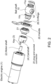
- Figure 1 is a perspective view of a motorised ball valve assembly including a dielectric insulation component according to the present disclosure.
- the operational part of the valve comprises a ball shaft 10 having a head part 11a defining a hole 12 therethrough defining a flow passage, and a shaft part 11b extending from the head for engagement with a drive part of the assembly.
- the valve is arranged in a water or fluid pipe system such that in a first rotational position of the ball shaft 10, the hole is aligned with a fluid pipe to form a flow passage from the pipe and through the hole 12.
- the ball shaft is rotated e.g. by one quarter turn, so that the hole is no longer aligned with the pipe and, instead, flow from the pipe is blocked by the body 13 of the ball shaft.
- Valves with several positions and several input/output ports are known.
- the ball shaft is rotated by means of an electric motor 1.
- the electric motor 1 drives a cam shaft 4 which engages with the ball shaft 10.
- the cam shaft 4 is provided with a key feature 3 that engages with a D-shaft 2 - i.e. a D-shaped shaft component extending from the motor.
- Rotation of the motor 1 causes rotation of the D-shaft 2 which, in turn, rotates the cam shaft 4 which rotates the ball shaft 10.
- Seals e.g. O-rings 8 are provided around the ball shaft 10 to prevent water passing into the electric part of the assembly.
- the cam shaft may be provided with a profile 9 to interface with indicators such as microswitches (not shown), or other forms of sensors or indicators, to provide an indication of the angular position of the shaft.
- indicators such as microswitches (not shown), or other forms of sensors or indicators, to provide an indication of the angular position of the shaft.
- a manual handle 6 is provided so that manual operation of the handle can rotate the ball shaft 10.
- the handle can be fitted to the assembly such that there is a form fitting or frictional engagement between them.
- a fixing element e.g. a locking pin (not shown) may be provided to secure the handle to the assembly.
- the various shafts and the key feature will often be made of metal e.g. steel. If there is a problem with the electrics at the motor end of the assembly, these would be transmitted directly to the ball shaft and can cause problems such as electric shocks or arcing.
- the assembly of the present disclosure includes a dielectric insulator connector 20 to be fitted between the ball shaft 10 (or, more generally, driven end) and the electric motor 1 (or, more generally, drive end).
- the dielectric insulation connector is structured to have dielectric properties and is shaped to provide torque transmission from the electric motor 1 to the ball shaft 10.
- the shape of the connector should be such as to be able to withstand a short torque peak if the ball shaft end is fixed or blocked.
- the connector is shaped to define lobes or ribs, or is otherwise non-circular, to engage with corresponding engagement features provided at the ball shaft and the cam shaft as described further below. The important thing is that the connector has a shape that can engage with the shafts between which it is located in a manner that torque applied to one of the shafts is transferred to the other shaft via the connector.
- the connector according to the disclosure may have different forms, as will be described further below, but it is a discrete component made from a body of dielectric material and has a shape arranged to mate with a corresponding shape on the cam shaft and/or the ball shaft or a bushing provided on the ball shaft 10.
- the mating structure should be such that any misalignment can be accommodated.
- the connector is a simple, re-usable component easily manufactured from a readily available starting material which can be appropriately shaped and then easily assembled and secured between the cam shaft (or, more generally drive end) and the ball shaft (or, more generally, driven end) to ensure reliable torque transfer between the ends.
- all of the components required for torque transfer are made of steel, particularly stainless steel expect for the dielectric connector 20 which functions as a dielectric barrier between the steel parts.
- the connector may have different shapes, as described below, ideally, to ensure reliable torque transmission, the shape should be such as to define multiple points of engagement, as such a structure has been found to transfer the required torque optimally.
- the camshaft pushes the connector, and the connector pushes the ball shaft. Multiple forces act on distances to the centre of moment.
- the connector and the mating parts of the drive end and the driven end should form a tight fit to reduce the effects of backlash and to ensure coaxiality.
- the connector can be e.g. machined to shape from tubing or can be moulded to shape.
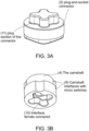
- the connector 20 is formed as a plug-and-socket component of dielectric material that is arranged to be fitted between the cam shaft 4 and the ball shaft 10 to form a dielectric barrier.
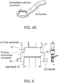
- the connector comprises a body 21 having, in the examples, an essentially circular cross-section such that the periphery of the body 21 essentially aligns axially with the outer shape of the cam shaft and the ball shaft such that, when assembled, the cam shaft, the connector and the shaft part of the ball shaft define an essentially cylindrical assembly (see e.g. Fig. 5 ).
- the body 21 can be of a different diameter to that of the cam and/or ball shaft.
- the connector further includes a protrusion 22 extending from one side 21a of the body and a recess or socket 23 formed in the other side 21b of the body 21.
- the protrusion 22 is shaped to be received in a correspondingly shaped recess or socket formed in one of the cam shaft or the ball shaft.
- the recess or socket 23 of the connector is shaped to receive a correspondingly shaped protrusion on the other of the cam shaft and the ball shaft.
- the provision of a connector 20 in the length of the assembly between the drive and the driven shafts also provides the opportunity to fit a manual handle 6 to the connector 20 rather than to one of the drive or driven shafts.
- the drive and driven shafts are usually made of metal and are therefore conductive. There is, therefore, a risk of an electric shock being passed to a user touching the handle 6 if it is mounted, as is typical, to the shafts.
- the handle can be fitted to the connector body.
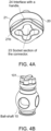
- the connector body is formed with a shaped interface 24 with which a handle interface 25 can engage (see Figs. 1 , 4A and 4C ). Again the interfaces 24 and 25 should have a matching and non-circular shape for torque transfer between the handle and the connector (and thus the ball shaft connected in torque transfer engagement with the connector).
- the connector 20 When the connector is assembled between the cam shaft and the ball shaft, as best seen in Fig. 5 , the connector 20 forms a dielectric barrier between the two shafts as the metal shafts are nowhere in direct electrically conductive contact with each other. Furthermore, the tight-fitting, shaped engagement between the connector and the shafts ensures torque transfer through the assembly.
- Fig. 6A shows by arrow R the torsional moment (torque) and the direction and arrows T represent multiple pairs of forces resulting from pressure loading between the cam shaft and the connector when the assembly is rotated in the direction of arrow R.
- Fig, 6C shows, by arrows T', the resultant forces between the connector and the ball shaft.
- Figs. 7A and 7B show examples in which the connector protrusion fits into a socket on the cam shaft and a protrusion on the ball shaft fits into a socket on the connector.
- Figs. 7C and 7D show examples in which the connector protrusion fits into a socket on the ball shaft and a protrusion on the cam shaft fits into a socket on the connector.
- a bore hole 18 is formed through the protrusion to make the connector more lightweight.
- dielectric materials can be used for the connector and can be selected depending on the required properties for the application e.g. dielectric properties, robustness, lightweight, cost, workability, corrosion resistance, thermal properties, long life, .
- Some examples include PEEK, carbon composite materials such as G10/FR4 or G11/FR5, Plasma electrolytic oxidation (PEO)-aluminium, ceramics etc. Zirconia, yttrium oxide (Y 2 O 3 ), rubber, etc.
- the material selected should have superior strength in terms of compression rather than in the tension or shear directions, as the torque is transferred in the compression direction as shown in Figs. 6B and 6C .
- Plastic and rubber materials allow the sleeve to buffer vibration or shocks sent by the motor through the system.
Landscapes
- Engineering & Computer Science (AREA)
- General Engineering & Computer Science (AREA)
- Mechanical Engineering (AREA)
- Taps Or Cocks (AREA)
Claims (9)
- Ensemble de transfert de couple comprenant un arbre d'entraînement (4) et un arbre à billes entraîné (10) et un connecteur diélectrique (20) positionné entre l'arbre d'entraînement et l'arbre à billes entraîné et reliant ces derniers, le connecteur comprenant un corps (21) en matériau diélectrique définissant une barrière isolante entre l'arbre d'entraînement et l'arbre à billes entraîné, le corps de barrière diélectrique (21) ayant un premier côté (21a) à partir duquel s'étend une saillie (22), la saillie étant configurée pour venir en prise dans un évidement de forme correspondante (41) formé dans l'un de l'arbre d'entraînement ou de l'arbre à billes entraîné, et un second côté (21b), opposé au premier côté, dans lequel est formé un évidement (23) formé pour recevoir une saillie de forme correspondante (101) s'étendant à partir de l'autre de l'arbre d'entraînement ou de l'arbre à billes entraîné, le connecteur constituant une barrière diélectrique entre l'arbre d'entraînement et l'arbre à billes entraîné ; caractérisé en ce que l'ensemble comprend une poignée (6) pour faire tourner manuellement l'arbre à billes, la poignée (6) étant reçue dans une rainure incluse dans le corps de connecteur (21).
- Ensemble selon la revendication 1, dans lequel la saillie (22) a une section transversale non circulaire.
- Ensemble selon la revendication 1 ou 2, dans lequel l'évidement (23) a une section transversale non circulaire.
- Ensemble selon une quelconque revendication précédente, dans lequel la saillie (22) a la forme d'une pluralité de lobes (22a).
- Ensemble selon une quelconque revendication précédente, dans lequel l'évidement (23) définit une pluralité d'évidements en forme de lobe.
- Ensemble selon une quelconque revendication précédente, comprenant également un moteur (1) agencé pour entraîner l'arbre à billes entraîné via un arbre à cames (4), en tant qu'arbre d'entraînement.
- Ensemble selon la revendication 6, dans lequel le moteur est un moteur électrique (1).
- Système d'alimentation en eau comprenant l'ensemble selon une quelconque revendication précédente.
- Système d'alimentation en eau selon la revendication 8, étant un système d'alimentation en eau pour aéronef.
Priority Applications (2)
| Application Number | Priority Date | Filing Date | Title |
|---|---|---|---|
| EP21461592.4A EP4148305B1 (fr) | 2021-09-13 | 2021-09-13 | Ensemble d'entraînement d'articulation souple |
| US17/943,555 US12460730B2 (en) | 2021-09-13 | 2022-09-13 | Compliant joint drive assembly |
Applications Claiming Priority (1)
| Application Number | Priority Date | Filing Date | Title |
|---|---|---|---|
| EP21461592.4A EP4148305B1 (fr) | 2021-09-13 | 2021-09-13 | Ensemble d'entraînement d'articulation souple |
Publications (2)
| Publication Number | Publication Date |
|---|---|
| EP4148305A1 EP4148305A1 (fr) | 2023-03-15 |
| EP4148305B1 true EP4148305B1 (fr) | 2025-03-12 |
Family
ID=77750222
Family Applications (1)
| Application Number | Title | Priority Date | Filing Date |
|---|---|---|---|
| EP21461592.4A Active EP4148305B1 (fr) | 2021-09-13 | 2021-09-13 | Ensemble d'entraînement d'articulation souple |
Country Status (2)
| Country | Link |
|---|---|
| US (1) | US12460730B2 (fr) |
| EP (1) | EP4148305B1 (fr) |
Families Citing this family (1)
| Publication number | Priority date | Publication date | Assignee | Title |
|---|---|---|---|---|
| EP4112979B1 (fr) * | 2021-06-29 | 2024-12-25 | Goodrich Corporation | Ensemble d'entraînement d'articulation souple |
Family Cites Families (11)
| Publication number | Priority date | Publication date | Assignee | Title |
|---|---|---|---|---|
| US3687415A (en) * | 1970-12-28 | 1972-08-29 | Hill Mccanna Co | Manually operable power actuated valve |
| US6155875A (en) | 1999-04-30 | 2000-12-05 | Mannesmann Vdo Ag | Multi-angle electrical connector |
| DE10156740A1 (de) | 2001-11-19 | 2003-05-28 | Linde Ag | Kupplung für kryogene Medien |
| US7303481B2 (en) * | 2005-02-04 | 2007-12-04 | Itt Manufacturing Enterprises, Inc. | Electrically isolated actuator output shaft |
| US8172198B2 (en) | 2007-08-09 | 2012-05-08 | Goodrich Corporation | Valve assembly for aircraft water supply system |
| FR2971310A3 (fr) * | 2011-02-08 | 2012-08-10 | Stanley Works Europe Gmbh | Dispositif d'accouplement en rotation isolant electriquement ameliore, et adaptateur pour outil comportant un tel dispositif |
| US9939458B2 (en) | 2015-08-27 | 2018-04-10 | General Electric Company | Insulated accelerometer assembly for high voltage environment |
| US20170130684A1 (en) | 2015-11-10 | 2017-05-11 | CS&P Technologies, LP | Air intake shut-off valve and methods thereof |
| US11027400B2 (en) * | 2017-05-02 | 2021-06-08 | Apex Brands, Inc. | Electrically isolated coupling |
| WO2019092141A1 (fr) | 2017-11-10 | 2019-05-16 | Covestro Deutschland Ag | Composition thermoplastique chargée de fibres de verre présentant de bonnes propriétés mécaniques |
| JP3219263U (ja) * | 2018-01-26 | 2018-12-13 | シュ タオタオXu Taotao | トルク入力端とトルク出力端との電気的に絶縁されたトルク伝達装置、その取付部品及びトルク伝達軸ユニット |
-
2021
- 2021-09-13 EP EP21461592.4A patent/EP4148305B1/fr active Active
-
2022
- 2022-09-13 US US17/943,555 patent/US12460730B2/en active Active
Also Published As
| Publication number | Publication date |
|---|---|
| US12460730B2 (en) | 2025-11-04 |
| US20230079424A1 (en) | 2023-03-16 |
| EP4148305A1 (fr) | 2023-03-15 |
Similar Documents
| Publication | Publication Date | Title |
|---|---|---|
| US12078261B2 (en) | Compliant joint drive assembly | |
| US11978574B2 (en) | Compliant joint drive assembly | |
| US12055232B2 (en) | Compliant joint drive assembly | |
| EP2766647B1 (fr) | Dispositif pour un actionneur de vanne à rappel par ressort et procédé de fonctionnement d'une vanne | |
| EP4148305B1 (fr) | Ensemble d'entraînement d'articulation souple | |
| EP1746225A2 (fr) | Dispositif de verrouillage | |
| US12173755B2 (en) | Compliant joint drive assembly | |
| EP4160063B1 (fr) | Actionneur de soupape | |
| US11052721B2 (en) | Stabilizer device | |
| US11906069B2 (en) | Compliant joint drive assembly | |
| CA2596836C (fr) | Arbre secondaire d'un actionneur a isolement electrique | |
| US10865892B2 (en) | Subsea valve with non-circular sliding metal seals | |
| AU6525994A (en) | Valve driver | |
| EP4112978B1 (fr) | Ensemble d'entraînement d'articulation souple | |
| EP4023916B1 (fr) | Ensemble de vanne à boisseau spérique | |
| US5788473A (en) | Integral close coupling for a rotary gear pump | |
| EP4390148B1 (fr) | Actionneur et soupape de commande directionnelle de type à tiroir | |
| KR102535504B1 (ko) | 전동 액츄에이터용 스위치 장치 | |
| CN114526369B (zh) | 一种能够实现远程操控操作手柄的液压机构 | |
| KR200444754Y1 (ko) | 밸브 개폐용 액츄에이터의 단열장치 |
Legal Events
| Date | Code | Title | Description |
|---|---|---|---|
| PUAI | Public reference made under article 153(3) epc to a published international application that has entered the european phase |
Free format text: ORIGINAL CODE: 0009012 |
|
| STAA | Information on the status of an ep patent application or granted ep patent |
Free format text: STATUS: THE APPLICATION HAS BEEN PUBLISHED |
|
| AK | Designated contracting states |
Kind code of ref document: A1 Designated state(s): AL AT BE BG CH CY CZ DE DK EE ES FI FR GB GR HR HU IE IS IT LI LT LU LV MC MK MT NL NO PL PT RO RS SE SI SK SM TR |
|
| STAA | Information on the status of an ep patent application or granted ep patent |
Free format text: STATUS: REQUEST FOR EXAMINATION WAS MADE |
|
| 17P | Request for examination filed |
Effective date: 20230913 |
|
| RBV | Designated contracting states (corrected) |
Designated state(s): AL AT BE BG CH CY CZ DE DK EE ES FI FR GB GR HR HU IE IS IT LI LT LU LV MC MK MT NL NO PL PT RO RS SE SI SK SM TR |
|
| P01 | Opt-out of the competence of the unified patent court (upc) registered |
Effective date: 20230922 |
|
| GRAP | Despatch of communication of intention to grant a patent |
Free format text: ORIGINAL CODE: EPIDOSNIGR1 |
|
| STAA | Information on the status of an ep patent application or granted ep patent |
Free format text: STATUS: GRANT OF PATENT IS INTENDED |
|
| INTG | Intention to grant announced |
Effective date: 20241018 |
|
| RIN1 | Information on inventor provided before grant (corrected) |
Inventor name: ZAJAC, PIOTR Inventor name: SEDLAK, LUKASZ Inventor name: TUREK, LUKASZ |
|
| GRAS | Grant fee paid |
Free format text: ORIGINAL CODE: EPIDOSNIGR3 |
|
| GRAA | (expected) grant |
Free format text: ORIGINAL CODE: 0009210 |
|
| STAA | Information on the status of an ep patent application or granted ep patent |
Free format text: STATUS: THE PATENT HAS BEEN GRANTED |
|
| AK | Designated contracting states |
Kind code of ref document: B1 Designated state(s): AL AT BE BG CH CY CZ DE DK EE ES FI FR GB GR HR HU IE IS IT LI LT LU LV MC MK MT NL NO PL PT RO RS SE SI SK SM TR |
|
| REG | Reference to a national code |
Ref country code: GB Ref legal event code: FG4D |
|
| REG | Reference to a national code |
Ref country code: CH Ref legal event code: EP |
|
| REG | Reference to a national code |
Ref country code: DE Ref legal event code: R096 Ref document number: 602021027473 Country of ref document: DE |
|
| REG | Reference to a national code |
Ref country code: IE Ref legal event code: FG4D |
|
| PG25 | Lapsed in a contracting state [announced via postgrant information from national office to epo] |
Ref country code: RS Free format text: LAPSE BECAUSE OF FAILURE TO SUBMIT A TRANSLATION OF THE DESCRIPTION OR TO PAY THE FEE WITHIN THE PRESCRIBED TIME-LIMIT Effective date: 20250612 |
|
| PG25 | Lapsed in a contracting state [announced via postgrant information from national office to epo] |
Ref country code: FI Free format text: LAPSE BECAUSE OF FAILURE TO SUBMIT A TRANSLATION OF THE DESCRIPTION OR TO PAY THE FEE WITHIN THE PRESCRIBED TIME-LIMIT Effective date: 20250312 |
|
| PG25 | Lapsed in a contracting state [announced via postgrant information from national office to epo] |
Ref country code: ES Free format text: LAPSE BECAUSE OF FAILURE TO SUBMIT A TRANSLATION OF THE DESCRIPTION OR TO PAY THE FEE WITHIN THE PRESCRIBED TIME-LIMIT Effective date: 20250312 |
|
| REG | Reference to a national code |
Ref country code: LT Ref legal event code: MG9D |
|
| PG25 | Lapsed in a contracting state [announced via postgrant information from national office to epo] |
Ref country code: NO Free format text: LAPSE BECAUSE OF FAILURE TO SUBMIT A TRANSLATION OF THE DESCRIPTION OR TO PAY THE FEE WITHIN THE PRESCRIBED TIME-LIMIT Effective date: 20250612 |
|
| PG25 | Lapsed in a contracting state [announced via postgrant information from national office to epo] |
Ref country code: HR Free format text: LAPSE BECAUSE OF FAILURE TO SUBMIT A TRANSLATION OF THE DESCRIPTION OR TO PAY THE FEE WITHIN THE PRESCRIBED TIME-LIMIT Effective date: 20250312 |
|
| REG | Reference to a national code |
Ref country code: NL Ref legal event code: MP Effective date: 20250312 |
|
| PG25 | Lapsed in a contracting state [announced via postgrant information from national office to epo] |
Ref country code: LV Free format text: LAPSE BECAUSE OF FAILURE TO SUBMIT A TRANSLATION OF THE DESCRIPTION OR TO PAY THE FEE WITHIN THE PRESCRIBED TIME-LIMIT Effective date: 20250312 |
|
| PG25 | Lapsed in a contracting state [announced via postgrant information from national office to epo] |
Ref country code: BG Free format text: LAPSE BECAUSE OF FAILURE TO SUBMIT A TRANSLATION OF THE DESCRIPTION OR TO PAY THE FEE WITHIN THE PRESCRIBED TIME-LIMIT Effective date: 20250312 Ref country code: GR Free format text: LAPSE BECAUSE OF FAILURE TO SUBMIT A TRANSLATION OF THE DESCRIPTION OR TO PAY THE FEE WITHIN THE PRESCRIBED TIME-LIMIT Effective date: 20250613 |
|
| REG | Reference to a national code |
Ref country code: AT Ref legal event code: MK05 Ref document number: 1775238 Country of ref document: AT Kind code of ref document: T Effective date: 20250312 |
|
| PG25 | Lapsed in a contracting state [announced via postgrant information from national office to epo] |
Ref country code: NL Free format text: LAPSE BECAUSE OF FAILURE TO SUBMIT A TRANSLATION OF THE DESCRIPTION OR TO PAY THE FEE WITHIN THE PRESCRIBED TIME-LIMIT Effective date: 20250312 |
|
| PG25 | Lapsed in a contracting state [announced via postgrant information from national office to epo] |
Ref country code: SE Free format text: LAPSE BECAUSE OF FAILURE TO SUBMIT A TRANSLATION OF THE DESCRIPTION OR TO PAY THE FEE WITHIN THE PRESCRIBED TIME-LIMIT Effective date: 20250312 |
|
| PG25 | Lapsed in a contracting state [announced via postgrant information from national office to epo] |
Ref country code: SM Free format text: LAPSE BECAUSE OF FAILURE TO SUBMIT A TRANSLATION OF THE DESCRIPTION OR TO PAY THE FEE WITHIN THE PRESCRIBED TIME-LIMIT Effective date: 20250312 |
|
| PG25 | Lapsed in a contracting state [announced via postgrant information from national office to epo] |
Ref country code: PT Free format text: LAPSE BECAUSE OF FAILURE TO SUBMIT A TRANSLATION OF THE DESCRIPTION OR TO PAY THE FEE WITHIN THE PRESCRIBED TIME-LIMIT Effective date: 20250714 |
|
| PGFP | Annual fee paid to national office [announced via postgrant information from national office to epo] |
Ref country code: DE Payment date: 20250820 Year of fee payment: 5 |
|
| PG25 | Lapsed in a contracting state [announced via postgrant information from national office to epo] |
Ref country code: IT Free format text: LAPSE BECAUSE OF FAILURE TO SUBMIT A TRANSLATION OF THE DESCRIPTION OR TO PAY THE FEE WITHIN THE PRESCRIBED TIME-LIMIT Effective date: 20250312 Ref country code: PL Free format text: LAPSE BECAUSE OF FAILURE TO SUBMIT A TRANSLATION OF THE DESCRIPTION OR TO PAY THE FEE WITHIN THE PRESCRIBED TIME-LIMIT Effective date: 20250312 |
|
| PGFP | Annual fee paid to national office [announced via postgrant information from national office to epo] |
Ref country code: GB Payment date: 20250822 Year of fee payment: 5 |
|
| PG25 | Lapsed in a contracting state [announced via postgrant information from national office to epo] |
Ref country code: AT Free format text: LAPSE BECAUSE OF FAILURE TO SUBMIT A TRANSLATION OF THE DESCRIPTION OR TO PAY THE FEE WITHIN THE PRESCRIBED TIME-LIMIT Effective date: 20250312 |
|
| PGFP | Annual fee paid to national office [announced via postgrant information from national office to epo] |
Ref country code: FR Payment date: 20250820 Year of fee payment: 5 |
|
| PG25 | Lapsed in a contracting state [announced via postgrant information from national office to epo] |
Ref country code: CZ Free format text: LAPSE BECAUSE OF FAILURE TO SUBMIT A TRANSLATION OF THE DESCRIPTION OR TO PAY THE FEE WITHIN THE PRESCRIBED TIME-LIMIT Effective date: 20250312 Ref country code: EE Free format text: LAPSE BECAUSE OF FAILURE TO SUBMIT A TRANSLATION OF THE DESCRIPTION OR TO PAY THE FEE WITHIN THE PRESCRIBED TIME-LIMIT Effective date: 20250312 |
|
| PG25 | Lapsed in a contracting state [announced via postgrant information from national office to epo] |
Ref country code: RO Free format text: LAPSE BECAUSE OF FAILURE TO SUBMIT A TRANSLATION OF THE DESCRIPTION OR TO PAY THE FEE WITHIN THE PRESCRIBED TIME-LIMIT Effective date: 20250312 |
|
| PG25 | Lapsed in a contracting state [announced via postgrant information from national office to epo] |
Ref country code: SK Free format text: LAPSE BECAUSE OF FAILURE TO SUBMIT A TRANSLATION OF THE DESCRIPTION OR TO PAY THE FEE WITHIN THE PRESCRIBED TIME-LIMIT Effective date: 20250312 |
|
| PG25 | Lapsed in a contracting state [announced via postgrant information from national office to epo] |
Ref country code: IS Free format text: LAPSE BECAUSE OF FAILURE TO SUBMIT A TRANSLATION OF THE DESCRIPTION OR TO PAY THE FEE WITHIN THE PRESCRIBED TIME-LIMIT Effective date: 20250712 |