EP2672594A1 - Vehicle on-board cable and vehicle - Google Patents
Vehicle on-board cable and vehicle Download PDFInfo
- Publication number
- EP2672594A1 EP2672594A1 EP11857933.3A EP11857933A EP2672594A1 EP 2672594 A1 EP2672594 A1 EP 2672594A1 EP 11857933 A EP11857933 A EP 11857933A EP 2672594 A1 EP2672594 A1 EP 2672594A1
- Authority
- EP
- European Patent Office
- Prior art keywords
- cable
- vehicle
- piece
- connection member
- connection device
- Prior art date
- Legal status (The legal status is an assumption and is not a legal conclusion. Google has not performed a legal analysis and makes no representation as to the accuracy of the status listed.)
- Granted
Links
Images





Classifications
-
- B—PERFORMING OPERATIONS; TRANSPORTING
- B60—VEHICLES IN GENERAL
- B60R—VEHICLES, VEHICLE FITTINGS, OR VEHICLE PARTS, NOT OTHERWISE PROVIDED FOR
- B60R16/00—Electric or fluid circuits specially adapted for vehicles and not otherwise provided for; Arrangement of elements of electric or fluid circuits specially adapted for vehicles and not otherwise provided for
- B60R16/02—Electric or fluid circuits specially adapted for vehicles and not otherwise provided for; Arrangement of elements of electric or fluid circuits specially adapted for vehicles and not otherwise provided for electric constitutive elements
-
- B—PERFORMING OPERATIONS; TRANSPORTING
- B60—VEHICLES IN GENERAL
- B60L—PROPULSION OF ELECTRICALLY-PROPELLED VEHICLES; SUPPLYING ELECTRIC POWER FOR AUXILIARY EQUIPMENT OF ELECTRICALLY-PROPELLED VEHICLES; ELECTRODYNAMIC BRAKE SYSTEMS FOR VEHICLES IN GENERAL; MAGNETIC SUSPENSION OR LEVITATION FOR VEHICLES; MONITORING OPERATING VARIABLES OF ELECTRICALLY-PROPELLED VEHICLES; ELECTRIC SAFETY DEVICES FOR ELECTRICALLY-PROPELLED VEHICLES
- B60L50/00—Electric propulsion with power supplied within the vehicle
- B60L50/10—Electric propulsion with power supplied within the vehicle using propulsion power supplied by engine-driven generators, e.g. generators driven by combustion engines
- B60L50/16—Electric propulsion with power supplied within the vehicle using propulsion power supplied by engine-driven generators, e.g. generators driven by combustion engines with provision for separate direct mechanical propulsion
-
- B—PERFORMING OPERATIONS; TRANSPORTING
- B60—VEHICLES IN GENERAL
- B60L—PROPULSION OF ELECTRICALLY-PROPELLED VEHICLES; SUPPLYING ELECTRIC POWER FOR AUXILIARY EQUIPMENT OF ELECTRICALLY-PROPELLED VEHICLES; ELECTRODYNAMIC BRAKE SYSTEMS FOR VEHICLES IN GENERAL; MAGNETIC SUSPENSION OR LEVITATION FOR VEHICLES; MONITORING OPERATING VARIABLES OF ELECTRICALLY-PROPELLED VEHICLES; ELECTRIC SAFETY DEVICES FOR ELECTRICALLY-PROPELLED VEHICLES
- B60L50/00—Electric propulsion with power supplied within the vehicle
- B60L50/50—Electric propulsion with power supplied within the vehicle using propulsion power supplied by batteries or fuel cells
- B60L50/60—Electric propulsion with power supplied within the vehicle using propulsion power supplied by batteries or fuel cells using power supplied by batteries
- B60L50/61—Electric propulsion with power supplied within the vehicle using propulsion power supplied by batteries or fuel cells using power supplied by batteries by batteries charged by engine-driven generators, e.g. series hybrid electric vehicles
-
- B—PERFORMING OPERATIONS; TRANSPORTING
- B60—VEHICLES IN GENERAL
- B60L—PROPULSION OF ELECTRICALLY-PROPELLED VEHICLES; SUPPLYING ELECTRIC POWER FOR AUXILIARY EQUIPMENT OF ELECTRICALLY-PROPELLED VEHICLES; ELECTRODYNAMIC BRAKE SYSTEMS FOR VEHICLES IN GENERAL; MAGNETIC SUSPENSION OR LEVITATION FOR VEHICLES; MONITORING OPERATING VARIABLES OF ELECTRICALLY-PROPELLED VEHICLES; ELECTRIC SAFETY DEVICES FOR ELECTRICALLY-PROPELLED VEHICLES
- B60L50/00—Electric propulsion with power supplied within the vehicle
- B60L50/50—Electric propulsion with power supplied within the vehicle using propulsion power supplied by batteries or fuel cells
- B60L50/60—Electric propulsion with power supplied within the vehicle using propulsion power supplied by batteries or fuel cells using power supplied by batteries
- B60L50/66—Arrangements of batteries
-
- B—PERFORMING OPERATIONS; TRANSPORTING
- B60—VEHICLES IN GENERAL
- B60L—PROPULSION OF ELECTRICALLY-PROPELLED VEHICLES; SUPPLYING ELECTRIC POWER FOR AUXILIARY EQUIPMENT OF ELECTRICALLY-PROPELLED VEHICLES; ELECTRODYNAMIC BRAKE SYSTEMS FOR VEHICLES IN GENERAL; MAGNETIC SUSPENSION OR LEVITATION FOR VEHICLES; MONITORING OPERATING VARIABLES OF ELECTRICALLY-PROPELLED VEHICLES; ELECTRIC SAFETY DEVICES FOR ELECTRICALLY-PROPELLED VEHICLES
- B60L53/00—Methods of charging batteries, specially adapted for electric vehicles; Charging stations or on-board charging equipment therefor; Exchange of energy storage elements in electric vehicles
- B60L53/10—Methods of charging batteries, specially adapted for electric vehicles; Charging stations or on-board charging equipment therefor; Exchange of energy storage elements in electric vehicles characterised by the energy transfer between the charging station and the vehicle
- B60L53/14—Conductive energy transfer
- B60L53/16—Connectors, e.g. plugs or sockets, specially adapted for charging electric vehicles
-
- B—PERFORMING OPERATIONS; TRANSPORTING
- B60—VEHICLES IN GENERAL
- B60L—PROPULSION OF ELECTRICALLY-PROPELLED VEHICLES; SUPPLYING ELECTRIC POWER FOR AUXILIARY EQUIPMENT OF ELECTRICALLY-PROPELLED VEHICLES; ELECTRODYNAMIC BRAKE SYSTEMS FOR VEHICLES IN GENERAL; MAGNETIC SUSPENSION OR LEVITATION FOR VEHICLES; MONITORING OPERATING VARIABLES OF ELECTRICALLY-PROPELLED VEHICLES; ELECTRIC SAFETY DEVICES FOR ELECTRICALLY-PROPELLED VEHICLES
- B60L53/00—Methods of charging batteries, specially adapted for electric vehicles; Charging stations or on-board charging equipment therefor; Exchange of energy storage elements in electric vehicles
- B60L53/10—Methods of charging batteries, specially adapted for electric vehicles; Charging stations or on-board charging equipment therefor; Exchange of energy storage elements in electric vehicles characterised by the energy transfer between the charging station and the vehicle
- B60L53/14—Conductive energy transfer
- B60L53/18—Cables specially adapted for charging electric vehicles
-
- B—PERFORMING OPERATIONS; TRANSPORTING
- B60—VEHICLES IN GENERAL
- B60L—PROPULSION OF ELECTRICALLY-PROPELLED VEHICLES; SUPPLYING ELECTRIC POWER FOR AUXILIARY EQUIPMENT OF ELECTRICALLY-PROPELLED VEHICLES; ELECTRODYNAMIC BRAKE SYSTEMS FOR VEHICLES IN GENERAL; MAGNETIC SUSPENSION OR LEVITATION FOR VEHICLES; MONITORING OPERATING VARIABLES OF ELECTRICALLY-PROPELLED VEHICLES; ELECTRIC SAFETY DEVICES FOR ELECTRICALLY-PROPELLED VEHICLES
- B60L53/00—Methods of charging batteries, specially adapted for electric vehicles; Charging stations or on-board charging equipment therefor; Exchange of energy storage elements in electric vehicles
- B60L53/30—Constructional details of charging stations
- B60L53/31—Charging columns specially adapted for electric vehicles
-
- B—PERFORMING OPERATIONS; TRANSPORTING
- B65—CONVEYING; PACKING; STORING; HANDLING THIN OR FILAMENTARY MATERIAL
- B65H—HANDLING THIN OR FILAMENTARY MATERIAL, e.g. SHEETS, WEBS, CABLES
- B65H63/00—Warning or safety devices, e.g. automatic fault detectors, stop-motions ; Quality control of the package
- B65H63/04—Warning or safety devices, e.g. automatic fault detectors, stop-motions ; Quality control of the package responsive to excessive tension or irregular operation of apparatus
-
- B—PERFORMING OPERATIONS; TRANSPORTING
- B65—CONVEYING; PACKING; STORING; HANDLING THIN OR FILAMENTARY MATERIAL
- B65H—HANDLING THIN OR FILAMENTARY MATERIAL, e.g. SHEETS, WEBS, CABLES
- B65H75/00—Storing webs, tapes, or filamentary material, e.g. on reels
- B65H75/02—Cores, formers, supports, or holders for coiled, wound, or folded material, e.g. reels, spindles, bobbins, cop tubes, cans, mandrels or chucks
- B65H75/34—Cores, formers, supports, or holders for coiled, wound, or folded material, e.g. reels, spindles, bobbins, cop tubes, cans, mandrels or chucks specially adapted or mounted for storing and repeatedly paying-out and re-storing lengths of material provided for particular purposes, e.g. anchored hoses, power cables
- B65H75/38—Cores, formers, supports, or holders for coiled, wound, or folded material, e.g. reels, spindles, bobbins, cop tubes, cans, mandrels or chucks specially adapted or mounted for storing and repeatedly paying-out and re-storing lengths of material provided for particular purposes, e.g. anchored hoses, power cables involving the use of a core or former internal to, and supporting, a stored package of material
- B65H75/40—Cores, formers, supports, or holders for coiled, wound, or folded material, e.g. reels, spindles, bobbins, cop tubes, cans, mandrels or chucks specially adapted or mounted for storing and repeatedly paying-out and re-storing lengths of material provided for particular purposes, e.g. anchored hoses, power cables involving the use of a core or former internal to, and supporting, a stored package of material mobile or transportable
- B65H75/42—Cores, formers, supports, or holders for coiled, wound, or folded material, e.g. reels, spindles, bobbins, cop tubes, cans, mandrels or chucks specially adapted or mounted for storing and repeatedly paying-out and re-storing lengths of material provided for particular purposes, e.g. anchored hoses, power cables involving the use of a core or former internal to, and supporting, a stored package of material mobile or transportable attached to, or forming part of, mobile tools, machines or vehicles
-
- H—ELECTRICITY
- H01—ELECTRIC ELEMENTS
- H01R—ELECTRICALLY-CONDUCTIVE CONNECTIONS; STRUCTURAL ASSOCIATIONS OF A PLURALITY OF MUTUALLY-INSULATED ELECTRICAL CONNECTING ELEMENTS; COUPLING DEVICES; CURRENT COLLECTORS
- H01R13/00—Details of coupling devices of the kinds covered by groups H01R12/70 or H01R24/00 - H01R33/00
- H01R13/62—Means for facilitating engagement or disengagement of coupling parts or for holding them in engagement
- H01R13/629—Additional means for facilitating engagement or disengagement of coupling parts, e.g. aligning or guiding means, levers, gas pressure electrical locking indicators, manufacturing tolerances
- H01R13/633—Additional means for facilitating engagement or disengagement of coupling parts, e.g. aligning or guiding means, levers, gas pressure electrical locking indicators, manufacturing tolerances for disengagement only
-
- H—ELECTRICITY
- H01—ELECTRIC ELEMENTS
- H01R—ELECTRICALLY-CONDUCTIVE CONNECTIONS; STRUCTURAL ASSOCIATIONS OF A PLURALITY OF MUTUALLY-INSULATED ELECTRICAL CONNECTING ELEMENTS; COUPLING DEVICES; CURRENT COLLECTORS
- H01R13/00—Details of coupling devices of the kinds covered by groups H01R12/70 or H01R24/00 - H01R33/00
- H01R13/72—Means for accommodating flexible lead within the holder
-
- H—ELECTRICITY
- H02—GENERATION; CONVERSION OR DISTRIBUTION OF ELECTRIC POWER
- H02G—INSTALLATION OF ELECTRIC CABLES OR LINES, OR OF COMBINED OPTICAL AND ELECTRIC CABLES OR LINES
- H02G11/00—Arrangements of electric cables or lines between relatively-movable parts
- H02G11/02—Arrangements of electric cables or lines between relatively-movable parts using take-up reel or drum
-
- B—PERFORMING OPERATIONS; TRANSPORTING
- B60—VEHICLES IN GENERAL
- B60L—PROPULSION OF ELECTRICALLY-PROPELLED VEHICLES; SUPPLYING ELECTRIC POWER FOR AUXILIARY EQUIPMENT OF ELECTRICALLY-PROPELLED VEHICLES; ELECTRODYNAMIC BRAKE SYSTEMS FOR VEHICLES IN GENERAL; MAGNETIC SUSPENSION OR LEVITATION FOR VEHICLES; MONITORING OPERATING VARIABLES OF ELECTRICALLY-PROPELLED VEHICLES; ELECTRIC SAFETY DEVICES FOR ELECTRICALLY-PROPELLED VEHICLES
- B60L2210/00—Converter types
- B60L2210/10—DC to DC converters
-
- B—PERFORMING OPERATIONS; TRANSPORTING
- B60—VEHICLES IN GENERAL
- B60L—PROPULSION OF ELECTRICALLY-PROPELLED VEHICLES; SUPPLYING ELECTRIC POWER FOR AUXILIARY EQUIPMENT OF ELECTRICALLY-PROPELLED VEHICLES; ELECTRODYNAMIC BRAKE SYSTEMS FOR VEHICLES IN GENERAL; MAGNETIC SUSPENSION OR LEVITATION FOR VEHICLES; MONITORING OPERATING VARIABLES OF ELECTRICALLY-PROPELLED VEHICLES; ELECTRIC SAFETY DEVICES FOR ELECTRICALLY-PROPELLED VEHICLES
- B60L2210/00—Converter types
- B60L2210/30—AC to DC converters
-
- B—PERFORMING OPERATIONS; TRANSPORTING
- B60—VEHICLES IN GENERAL
- B60L—PROPULSION OF ELECTRICALLY-PROPELLED VEHICLES; SUPPLYING ELECTRIC POWER FOR AUXILIARY EQUIPMENT OF ELECTRICALLY-PROPELLED VEHICLES; ELECTRODYNAMIC BRAKE SYSTEMS FOR VEHICLES IN GENERAL; MAGNETIC SUSPENSION OR LEVITATION FOR VEHICLES; MONITORING OPERATING VARIABLES OF ELECTRICALLY-PROPELLED VEHICLES; ELECTRIC SAFETY DEVICES FOR ELECTRICALLY-PROPELLED VEHICLES
- B60L2210/00—Converter types
- B60L2210/40—DC to AC converters
-
- B—PERFORMING OPERATIONS; TRANSPORTING
- B60—VEHICLES IN GENERAL
- B60L—PROPULSION OF ELECTRICALLY-PROPELLED VEHICLES; SUPPLYING ELECTRIC POWER FOR AUXILIARY EQUIPMENT OF ELECTRICALLY-PROPELLED VEHICLES; ELECTRODYNAMIC BRAKE SYSTEMS FOR VEHICLES IN GENERAL; MAGNETIC SUSPENSION OR LEVITATION FOR VEHICLES; MONITORING OPERATING VARIABLES OF ELECTRICALLY-PROPELLED VEHICLES; ELECTRIC SAFETY DEVICES FOR ELECTRICALLY-PROPELLED VEHICLES
- B60L2220/00—Electrical machine types; Structures or applications thereof
- B60L2220/10—Electrical machine types
- B60L2220/14—Synchronous machines
-
- B—PERFORMING OPERATIONS; TRANSPORTING
- B65—CONVEYING; PACKING; STORING; HANDLING THIN OR FILAMENTARY MATERIAL
- B65H—HANDLING THIN OR FILAMENTARY MATERIAL, e.g. SHEETS, WEBS, CABLES
- B65H2701/00—Handled material; Storage means
- B65H2701/30—Handled filamentary material
- B65H2701/34—Handled filamentary material electric cords or electric power cables
-
- H—ELECTRICITY
- H01—ELECTRIC ELEMENTS
- H01R—ELECTRICALLY-CONDUCTIVE CONNECTIONS; STRUCTURAL ASSOCIATIONS OF A PLURALITY OF MUTUALLY-INSULATED ELECTRICAL CONNECTING ELEMENTS; COUPLING DEVICES; CURRENT COLLECTORS
- H01R2105/00—Three poles
-
- Y—GENERAL TAGGING OF NEW TECHNOLOGICAL DEVELOPMENTS; GENERAL TAGGING OF CROSS-SECTIONAL TECHNOLOGIES SPANNING OVER SEVERAL SECTIONS OF THE IPC; TECHNICAL SUBJECTS COVERED BY FORMER USPC CROSS-REFERENCE ART COLLECTIONS [XRACs] AND DIGESTS
- Y02—TECHNOLOGIES OR APPLICATIONS FOR MITIGATION OR ADAPTATION AGAINST CLIMATE CHANGE
- Y02T—CLIMATE CHANGE MITIGATION TECHNOLOGIES RELATED TO TRANSPORTATION
- Y02T10/00—Road transport of goods or passengers
- Y02T10/60—Other road transportation technologies with climate change mitigation effect
- Y02T10/62—Hybrid vehicles
-
- Y—GENERAL TAGGING OF NEW TECHNOLOGICAL DEVELOPMENTS; GENERAL TAGGING OF CROSS-SECTIONAL TECHNOLOGIES SPANNING OVER SEVERAL SECTIONS OF THE IPC; TECHNICAL SUBJECTS COVERED BY FORMER USPC CROSS-REFERENCE ART COLLECTIONS [XRACs] AND DIGESTS
- Y02—TECHNOLOGIES OR APPLICATIONS FOR MITIGATION OR ADAPTATION AGAINST CLIMATE CHANGE
- Y02T—CLIMATE CHANGE MITIGATION TECHNOLOGIES RELATED TO TRANSPORTATION
- Y02T10/00—Road transport of goods or passengers
- Y02T10/60—Other road transportation technologies with climate change mitigation effect
- Y02T10/70—Energy storage systems for electromobility, e.g. batteries
-
- Y—GENERAL TAGGING OF NEW TECHNOLOGICAL DEVELOPMENTS; GENERAL TAGGING OF CROSS-SECTIONAL TECHNOLOGIES SPANNING OVER SEVERAL SECTIONS OF THE IPC; TECHNICAL SUBJECTS COVERED BY FORMER USPC CROSS-REFERENCE ART COLLECTIONS [XRACs] AND DIGESTS
- Y02—TECHNOLOGIES OR APPLICATIONS FOR MITIGATION OR ADAPTATION AGAINST CLIMATE CHANGE
- Y02T—CLIMATE CHANGE MITIGATION TECHNOLOGIES RELATED TO TRANSPORTATION
- Y02T10/00—Road transport of goods or passengers
- Y02T10/60—Other road transportation technologies with climate change mitigation effect
- Y02T10/7072—Electromobility specific charging systems or methods for batteries, ultracapacitors, supercapacitors or double-layer capacitors
-
- Y—GENERAL TAGGING OF NEW TECHNOLOGICAL DEVELOPMENTS; GENERAL TAGGING OF CROSS-SECTIONAL TECHNOLOGIES SPANNING OVER SEVERAL SECTIONS OF THE IPC; TECHNICAL SUBJECTS COVERED BY FORMER USPC CROSS-REFERENCE ART COLLECTIONS [XRACs] AND DIGESTS
- Y02—TECHNOLOGIES OR APPLICATIONS FOR MITIGATION OR ADAPTATION AGAINST CLIMATE CHANGE
- Y02T—CLIMATE CHANGE MITIGATION TECHNOLOGIES RELATED TO TRANSPORTATION
- Y02T10/00—Road transport of goods or passengers
- Y02T10/60—Other road transportation technologies with climate change mitigation effect
- Y02T10/72—Electric energy management in electromobility
-
- Y—GENERAL TAGGING OF NEW TECHNOLOGICAL DEVELOPMENTS; GENERAL TAGGING OF CROSS-SECTIONAL TECHNOLOGIES SPANNING OVER SEVERAL SECTIONS OF THE IPC; TECHNICAL SUBJECTS COVERED BY FORMER USPC CROSS-REFERENCE ART COLLECTIONS [XRACs] AND DIGESTS
- Y02—TECHNOLOGIES OR APPLICATIONS FOR MITIGATION OR ADAPTATION AGAINST CLIMATE CHANGE
- Y02T—CLIMATE CHANGE MITIGATION TECHNOLOGIES RELATED TO TRANSPORTATION
- Y02T90/00—Enabling technologies or technologies with a potential or indirect contribution to GHG emissions mitigation
- Y02T90/10—Technologies relating to charging of electric vehicles
- Y02T90/12—Electric charging stations
-
- Y—GENERAL TAGGING OF NEW TECHNOLOGICAL DEVELOPMENTS; GENERAL TAGGING OF CROSS-SECTIONAL TECHNOLOGIES SPANNING OVER SEVERAL SECTIONS OF THE IPC; TECHNICAL SUBJECTS COVERED BY FORMER USPC CROSS-REFERENCE ART COLLECTIONS [XRACs] AND DIGESTS
- Y02—TECHNOLOGIES OR APPLICATIONS FOR MITIGATION OR ADAPTATION AGAINST CLIMATE CHANGE
- Y02T—CLIMATE CHANGE MITIGATION TECHNOLOGIES RELATED TO TRANSPORTATION
- Y02T90/00—Enabling technologies or technologies with a potential or indirect contribution to GHG emissions mitigation
- Y02T90/10—Technologies relating to charging of electric vehicles
- Y02T90/14—Plug-in electric vehicles
Definitions
- the present invention relates to a vehicle-mounted cable and a vehicle, and more specifically to a vehicle-mounted cable pulled out outside a vehicle and a vehicle having that vehicle-mounted cable mounted therein.
- Japanese Patent Laying-Open No. 11-299008 (PTD 1) describes an electric vehicle including a battery, a charging cable connected to the battery and disposed in a storage room, a vehicular connector provided at an end of the charging cable, and a cylinder provided to penetrate a wall of the storage room and having the vehicular connector detachably connected thereto.
- PTD 1 Japanese Patent Laying-Open No. 11-299008
- Japanese Patent Laying-Open No. 2008-136346 (PTD 2) describes a charging system including a branch line branched from a trunk line, a hooking connector connected to a device, an intermediate cable having one end connected to the hooking connector, and an intermediate joint connected to the branch line and the intermediate cable.
- the intermediate joint includes a flat-blade connector provided at the branch line and a flat-blade plug connected to the intermediate cable.
- Japanese Patent Laying-Open No. 2010-158136 (PTD 3) describes a cabling structure including an electric conduction cable that couples between a charging device and an electric vehicle, and a load detection cable.
- the load detection cable is provided with a re-couplable separation unit that is provided between a portion coupled with the charging device and the other, coupled end of the load detection cable and is separated when a prescribed load is applied.
- Japanese Patent Laying-Open No. 5-328532 (PTD 4) describes a suspended charger including a safety joint that is provided at an intermediate portion of a cable having an end provided with a connector and is separated by tension.
- Japanese Patent Laying-Open No. 8-236206 (PTD 5) describes a device to select allowing/disallowing a connector to be disconnected, that includes a male connector secured to a device and a female connector that has a cable connected thereto and is provided with the male connector detachably.
- Japanese Utility Model Registration No. 3097567 (PTD 6) describes a USB cable including a mechanism to reel up a cable.
- the charging system described in Japanese Patent Laying-Open No. 2008-136346 is provided outside a vehicle, rather than mounted therein, and so is the cabling structure described in Japanese Patent Laying-Open No. 2010-158136 .
- the suspended charger described in Japanese Patent Laying-Open No. 5-328532 is not mounted in a vehicle, nor is the cable reel up mechanism described in Utility Model Registration No. 3097567 .
- the present invention has been made in view of the above issue, and an object of the present invention is to provide a vehicle-mounted cable mounted in a vehicle and pulled out through a port formed in the vehicle, that can minimize/prevent damage to an end of a cable connected to the vehicle, and a vehicle including that vehicle-mounted cable.
- a vehicle-mounted cable is mounted in a vehicle provided with a cable port.
- the vehicle-mounted cable includes: a first cable that can be pulled out through the cable port; a second cable connected to the vehicle; and a connection device that connects the first cable and the second cable together, and disconnects the first cable and the second cable when the connection device experiences tension equal to or larger than a prescribed tension.
- the connection device is provided at a position allowing the connection device to be pulled out through the cable port.
- connection device when the connection device is pulled out through the cable port, an end of the second cable connected to the vehicle is tensioned.
- the connection device includes a first connection member associated with the first cable and a second connection member associated with the second cable and capable of engaging with the first connection member.
- the second connection member includes a receiving portion provided to cover at least a portion of the first connection member.
- tension equal to or larger than the prescribed tension is exerted between the first connection member and the second connection member, the receiving portion deforms to be open so as to disconnect the first connection member and the second connection member.
- the cable port has an opening having an edge that catches the receiving portion in an open position and prevents the receiving portion in the open position from entering the vehicle past the cable port.
- the receiving portion includes a base, a first piece provided at the base and attached to an external circumferential surface of the first connection member, a second piece provided at the base and movable away from the first piece, a biasing member biasing the first piece and the second piece to cause the first piece and the second piece to straddle wide therebetween, and an engagement portion engaging the first piece and the second piece together.
- the engagement portion disengages when the first connection member and the second connection member experience tension equal to or larger than the prescribed tension.
- the first connection member includes a spherical portion, and the first piece and the second piece are formed to have a surface curved to cover the spherical portion.
- the base is provided with a terminal, and the first piece is secured to the base.
- a vehicle includes: the above vehicle-mounted cable, a battery, and a switching element provided between the battery and the vehicle-mounted cable, the switching element disconnecting the battery and the vehicle-mounted cable when the first cable and the second cable are disconnected.
- the present vehicle-mounted cable and vehicle including that vehicle-mounted cable can minimize/prevent excessive tension otherwise exerted to those portions of the vehicle-mounted cable and vehicle that are connected together.
- Fig. 1 to Fig. 14 describe a vehicle-mounted cable and a vehicle including that vehicle-mounted cable according to an embodiment. Note that while the following embodiment will be described for an example with the present cable and vehicle applied to a so called hybrid vehicle, it is also applicable to an electric vehicle.
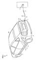
- Fig. 1 is a rearward perspective view of a vehicle according to the present, first embodiment.
- vehicle 10 includes a body 10a serving as a shell of the vehicle, a battery B and a fuel tank FT mounted in vehicle 10, and a cable accommodation device 30 mounted in vehicle 10 and having a vehicle-mounted cable 20 wound thereon.
- Body 10a includes a back side 12 having a cable port 11 allowing vehicle-mounted cable 20 to be pulled out therethrough and a lateral side 14 having a fuel port 13.
- Battery B is a power storage that can store power therein and is connected to cable accommodation device 30 via a converter or the like as will be described hereinafter.
- Battery B can be a nickel metal hydride battery, a lithium ion battery, a lead battery or a similar rechargeable battery, for example. Furthermore, battery B may be replaced with an electric double layer capacitor of large capacity.
- Fuel tank FT receives fuel such as gasoline and light oil fed through fuel port 13 and stores the fuel therein. Fuel tank FT is disposed in vehicle 10 closer to the front side than battery B.
- Cable accommodation device 30 is disposed near back side 12.
- Vehicle-mounted cable 20 includes an electric conduction cable 19 accommodated in cable accommodation device 30 and a plug 21 provided at a distal end of electric conduction cable 19.
- Plug 21 is connectable to a power supply 17 external to vehicle 10.
- Plug 21 can be connected to power supply 17 to charge battery B with power received from power supply 17.
- power supply 17 is a household power supply, a commercial power supply provided in a charging station or similar charging facilities, or the like.
- FIG. 2 is a block diagram showing vehicle 10.
- Vehicle 10 includes an engine 1, motor generators MG1 and MG2, a power split device 2, battery B, a capacitor C, a reactor L, a converter 4, inverters 5 and 6, a vehicular electronic control unit (vehicular ECU) 7, a switching element 8, and a converter 9.
- Power split device 2 is coupled with engine 1 and motor generators MG1 and MG2 and distributes power therebetween.
- power split device 2 is a planetary gear mechanism having three axes of rotation, i.e., a sun gear, a planetary carrier and a ring gear. These three axes of rotation are connected to engine 1 and motor generators MG1 and MG2 at their respective axes of rotation.
- engine 1 and motor generators MG1 and MG2 can mechanically be connected to power split device 2 by making a rotor of motor generator MG1 hollow and passing a crankshaft of engine 1 through a center thereof.
- motor generator MG2 has its axis of rotation coupled with a driving wheel, or a front wheel 3, by a reduction gear, a differential gear or the like (not shown).
- Power split device 2 may have a speed reducer further incorporated therein for the axis of rotation of motor generator MG2.
- Motor generator MG1 is incorporated in vehicle 10 as operating as a power generator driven by engine 1 and as an electric motor that can start engine 1.
- Motor generator MG2 is incorporated in vehicle 10 as an electric motor that drives the driving wheel or front wheel 3 of vehicle 10.
- Motor generator MG1, MG2 is a three-phase alternating synchronous motor, for example.
- Motor generator MG1, MG2 includes a three-phase coil formed of a U phase coil, a V phase coil, and a W phase coil as a stator coil.
- Motor generator MG1 uses the engine's output to generate three-phase alternating voltage, and outputs the generated three-phase alternating voltage to inverter 5. Motor generator MG1 receives three-phase alternating voltage from inverter 6 and thereby generates driving force to start engine 1.
- Motor generator MG2 receives three-phase alternating voltage from inverter 6 and thereby generates a torque to drive the vehicle. When the vehicle is regeneratively braked, motor generator MG2 generates and outputs three-phase alternating voltage to inverter 6.
- Switching element 8 and converter 9 are disposed between battery B and cable accommodation device 30.
- Converter 9 is connected to cable accommodation device 30, and switching element 8 is disposed between battery B and converter 9.
- Switching element 8 connects and disconnects converter 9 and battery B. Switching element 8 is switched on and off by a control signal CNTL1 issued by vehicular ECU 7.
- Converter 9 receives an alternating current from power supply 17, converts the alternating current into a direct current, and supplies the direct current to battery B. Furthermore, in returning the power that is stored in battery B to power supply 17, converter 9 receives a direct current from battery B, converts the direct current into an alternating current, and supplies the alternating current to cable accommodation device 30. Converter 9 is driven in response to a control signal CNTL2 issued by vehicular ECU 7.
- vehicular ECU 7 In charging battery B, vehicular ECU 7 turns on switching element 8 to connect battery B and converter 9. Then, vehicular ECU 7 drives converter 9 to convert the alternating current power that is supplied from power supply 17 into direct current power.
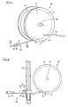
- Fig. 3 is a perspective view of cable accommodation device 30 and Fig. 4 is a side view schematically showing a relative positional relationship between cable accommodation device 30 and back side 12.
- cable accommodation device 30 includes a cylindrical bobbin 31 having a circumferential surface with vehicle-mounted cable 20 wound thereon, a support plate 32 provided to bobbin 31 at opposite ends and supporting vehicle-mounted cable 20, a rotating shaft 33 rotatably supporting bobbin 31, a power line 34, and a connection mechanism electrically connecting power line 34 and vehicle-mounted cable 20.
- Rotating shaft 33 is rotatably supported by body 10a for example.
- Vehicle-mounted cable 20 is fed as bobbin 31 rotates in a direction of rotation R shown in the figure, and vehicle-mounted cable 20 is reeled up by bobbin 31 as bobbin 31 rotates in a direction opposite to direction of rotation R.
- Power line 34 connects an end portion of vehicle-mounted cable 20 and converter 9.
- the connection mechanism is provided in bobbin 31, and includes a rotor that rotates as bobbin 31 rotates and that has the end portion of vehicle-mounted cable 20 connected thereto, a stator that is positionally fixed and thus does not rotate, and a terminal electrically connecting the stator and the rotor.
- the rotor has the end portion of vehicle-mounted cable 20 connected thereto, and vehicle-mounted cable 20 is connected to power line 34 via the rotor, the terminal and the stator. Note that power line 34 is connected to converter 9.
- body 10a has, at back side 12, a lid 11a to open and close cable port 11 and a plug housing portion 35 to house plug 21 therein.
- the user charges battery B, the user can open lid 11a and pull out plug 21 that is housed in plug housing portion 35 through cable port 11.
- Fig. 5 is a perspective view of cable accommodation device 30 with vehicle-mounted cable 20 fully pulled out.
- Fig. 6 is a side view showing a relative positional relationship between cable accommodation device 30 and body 10a, with vehicle-mounted cable 20 fully pulled out as shown in Fig. 5 .
- vehicle-mounted cable 20 includes plug 21, a first cable 22 having a distal end 23 provided with plug 21, a second cable 25 having a proximal end 26 connected to cable accommodation device 30, and a connection device 40 connecting a proximal end 24 of first cable 22 and a distal end 27 of second cable 25 together.
- Connection device 40 disconnects first cable 22 and second cable 25 when connection device 40 experiences tension equal to or larger than prescribed tension.
- Connection device 40 is provided at a position allowing connection device 40 to be pulled out through cable port 11. In the present embodiment when vehicle-mounted cable 20 is fully pulled out, connection device 40 is exposed outside the vehicle past cable port 11.
- second cable 25 When vehicle-mounted cable 20 is fully pulled out, second cable 25 is tensioned and second cable 25 experiences tension at proximal end 26.
- connection device 40 disconnects first cable 22 and second cable 25 to minimize/prevent excessively large load otherwise exerted to those portions of second cable 25 and cable accommodation device 30 that are connected together. This protects those portions of second cable 25 and cable accommodation device 30 in vehicle 10 that are connected together.
- connection device 40 is exposed outside vehicle 10, and can thus be easily repaired.
- connection device 40 includes a first connection member 41 provided at proximal end 24 of first cable 22 and a second connection member 42 provided at distal end 27 of second cable 25.
- First connection member 41 includes a spherical portion 60 and a cylindrical portion 61 having a proximal end connected to spherical portion 60. Cylindrical portion 61 has a distal end connected to proximal end 24 of first cable 22.
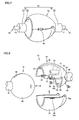
- Fig. 8 is an exploded perspective view of connection device 40 and Fig. 9 is a front view of spherical portion 60 as seen a direction IX shown in Fig. 8 .
- spherical portion 60 is formed generally spherically.
- a portion having cylindrical portion 61 connected thereto is a distal end and a portion opposite to cylindrical portion 61 is a proximal end for the sake of illustration.
- spherical portion 60 has a portion closer to the proximal end provided with a plurality of holes 62, 63, 64 provided with terminals 65, 66, 67, respectively.
- terminals 65 and 66 are power terminals and terminal 67 is for example a signaling or grounding terminal.
- Fig. 10 is a cross section of connection device 40. As shown in Fig. 10 , first cable 22 is connected to cylindrical portion 61, and each terminal such as terminal 65 is connected to a signal line, a power line and/or the like in first cable 22.
- First cable 22 has proximal end 24 with a threaded portion, whereas cylindrical portion 61 has an internal circumferential surface threaded to serve as a female screw, and threaded portion 70 is screwed into the female screw. Threaded portion 70 and cylindrical portion 61 are thus detachably attachable.
- second connection member 42 includes a receiving portion 43 provided to encapsulate at least a portion of spherical portion 60 of first connection member 41, and a cylindrical portion 44 provided with receiving portion 43 and having second cable 25 connected thereto.
- Receiving portion 43 for first connection member 41 includes a base 45 having cylindrical portion 44 connected thereto, a plurality of pieces 46 and 47 provided at base 45, an engagement portion 49 engaging pieces 46 and 47 together, and a resilient member 48.
- cylindrical portion 44 has an internal circumferential surface threaded to serve as a female screw, whereas second cable 25 has distal end 27 with a threaded portion 71, and cylindrical portion 44 receives threaded portion 71.
- Base 45 includes a shaft 50 rotatably supporting piece 47, terminals 51, 52, 53 provided at a contact surface 55 that spherical portion 60 contacts, and a contact sensor 54 provided on contact surface 55. Shaft 50 is inserted in a hole 50a formed through piece 47.
- contact surface 55 is formed to have a curved surface extending along an external surface of spherical portion 60.
- Terminals 51 and 52 are power terminals and connected to a power line in second cable 25.
- Terminal 53 is connected to a ground line, a signal line and/or the like provided in second cable 25, for example.
- Terminals 51-53 are formed cylindrically and adapted to be capable of receiving terminals 65, 66, 67 provided at first connection member 41.
- Contact sensor 54 is connected to a signal line 56 provided in second cable 25, as shown in Fig. 10 .
- Signal line 56 is connected to vehicular ECU 7 shown in Fig. 2 .
- Contact sensor 54 is adapted to be capable of sensing whether first connection member 41 and second connection member 42 are connected together. When first connection member 41 and second connection member 42 are connected together, contact sensor 54 contacts spherical portion 60. When contact sensor 54 no longer contacts spherical portion 60, contact sensor 54 transmits a signal to vehicular ECU 7. Vehicular ECU 7 receives the signal from contact sensor 54 and in response disconnects switching element 8 shown in Fig. 2 .
- Piece 46 is secured to base 45.
- Piece 46 is formed so as to project from base 45 and provided to cover terminals 51, 52, 53 provided at base 45.
- Piece 46 is formed to have a surface curved along an external surface of spherical portion 60.
- Piece 46 has an internal surface extending along an external surface of spherical portion 60 and having a projection 57 extending from a distal end of piece 46 to reach base 45.
- projection 57 fits in a slit 68 formed on spherical portion 60 and thus prevents spherical portion 60 from rotating.
- Piece 46 has an edge provided with a tab 59. As shown in Fig. 10 , piece 46 extends from base 45 along an external surface of spherical portion 60 beyond a center point O toward cylindrical portion 61.
- piece 47 has a joint having hole 50a receiving shaft 50, and piece 47 is provided to be pivotable relative to base 45.
- Piece 47 has an external circumferential surface having a groove 58 to engage with tab 59.
- Tab 59 and groove 58 are adapted to be capable of engaging with each other, and engagement portion 49 includes tab 59 and groove 58, and when tab 59 is engaged with groove 58, piece 46 and piece 47 are coupled together.
- Piece 47 is also formed to have a surface curved to extend along an external surface of spherical portion 60. When first connection member 41 and second connection member 42 are connected together, piece 47 extends from a circumferential surface of base 45 along spherical portion 60 beyond center point O toward cylindrical portion 61, as shown in Fig. 10 .
- contact surface 55, piece 46, and piece 47 cooperate with each other to cover a surface of spherical portion 60 at a portion extending from a proximal end of spherical portion 60 beyond center point O toward cylindrical portion 61.
- Spherical portion 60 is increased in thickness as seen at its proximal end toward center point O and decreased in thickness as seen at center point O toward its distal end.
- receiving portion 43 engages with spherical portion 60, and first connection member 41 and second connection member 42 are coupled together.
- spherical portion 60 may be provided in the form of a rugby ball.
- Resilient member 48 is provided at a circumference of shaft 50 and biases piece 47 away from piece 46.
- Fig. 11 is a perspective view of first connection member 41 and second connection member 42 with pieces 46 and 47 disengaged
- Fig. 12 is a cross section of connection device 40 with pieces 46 and 47 disengaged.
- resilient member 48 keeps piece 47 away from piece 46 and thus holds receiving portion 43 open.
- Receiving portion 43 in the open position has a width larger than that of the opening of cable port 11, and the opening of cable port 11 has an edge that can catch receiving portion 43 in the open position.
- first connection member 41 and second connection member 42 have been disengaged, receiving portion 43 is prevented from entering vehicle 10, and first connection member 41 and second connection member 42 can be easily re-coupled together.
- piece 46 and piece 47 can be attached to a circumferential surface of spherical portion 60 that has come off and tab 59 engaged with groove 58 to re-couple first connection member 41 and second connection member 42 together.
- connection device 40 can be decoupled to minimize/prevent excessive load otherwise exerted to those portions of second cable 25 and vehicle 10 that are connected together.
- connection device 40 is externally pulled out from cable port 11.
- first connection member 41 and second connection member 42 are disconnected and receiving portion 43 opens, receiving portion 43 is located outside vehicle 10, and first connection member 41 and second connection member 42 can subsequently be easily coupled together.
- vehicular ECU 7 operates in response to a signal received from contact sensor 54 to disconnect switching element 8 shown in Fig. 2 , which can prevent terminals 51, 52, 53 from being externally exposed with voltage applied thereto.
- Piece 46 is provided such that it covers terminals 51, 52, 53 provided at base 45, and when first connection member 41 and second connection member 42 are disconnected, piece 46 can function as a protective cover to protect terminals 51, 52, 53 from damage.
- first connection member 41 and second connection member 42 should be damaged, threaded portions 70 and 71 can be removed from cylindrical portions 61 and 44 to facilitate replacing first connection member 41 and second connection member 42.
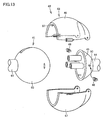
- vehicle-mounted cable 20 shown in Fig. 7 to Fig. 12 has been described for an example with piece 46 secured to base 45, piece 46 and piece 47 may be pivotable about base 45, as shown in Fig. 13 or the like.
- piece 46 is also rotatably supported by shaft 50, and resilient member 48 biases piece 46 and piece 47 so that piece 46 and piece 47 mutually open.
- Fig. 14 is a cross section of connection device 40 of vehicle-mounted cable 20 shown in Fig. 13 , as seen when connection device 40 is disconnected.
- the present invention is applicable to vehicle-mounted cables and vehicles.
Landscapes
- Engineering & Computer Science (AREA)
- Mechanical Engineering (AREA)
- Power Engineering (AREA)
- Transportation (AREA)
- Life Sciences & Earth Sciences (AREA)
- Sustainable Development (AREA)
- Sustainable Energy (AREA)
- Quality & Reliability (AREA)
- Electric Propulsion And Braking For Vehicles (AREA)
- Details Of Connecting Devices For Male And Female Coupling (AREA)
- Insulated Conductors (AREA)
Abstract
Description
- The present invention relates to a vehicle-mounted cable and a vehicle, and more specifically to a vehicle-mounted cable pulled out outside a vehicle and a vehicle having that vehicle-mounted cable mounted therein.
- Conventionally, there have been proposed a variety of cables mounted in vehicles and vehicles having such cables mounted therein.
- For example, Japanese Patent Laying-Open No.
11-299008 - Furthermore, in the field of cables, a variety of configurations have been proposed for minimizing/preventing excessive load exerted to cables.
- For example, Japanese Patent Laying-Open No.
2008-136346 - Japanese Patent Laying-Open No.
2010-158136 - Japanese Patent Laying-Open No.
5-328532 - Japanese Patent Laying-Open No.
8-236206 - Japanese Utility Model Registration No.
3097567 -
- PTD 1: Japanese Patent Laying-Open No.
11-299008 - PTD 2: Japanese Patent Laying-Open No.
2008-136346 - PTD 3: Japanese Patent Laying-Open No.
2010-158136 - PTD 4: Japanese Patent Laying-Open No.
5-328532 - PTD 5: Japanese Patent Laying-Open No.
8-236206 - PTD 6: Japanese Utility Model Registration No.
3097567 - When the charging cable and electric vehicle described in Japanese Patent Laying-Open No.
11-299008 - The charging system described in Japanese Patent Laying-Open No.
2008-136346 2010-158136 5-328532 3097567 - When a cable mounted in a vehicle and having one end connected the vehicle experiences significant tension, the above patent documents do not provide a solution to prevent the vehicle and the cable from having their mutually connected portions damaged.
- The present invention has been made in view of the above issue, and an object of the present invention is to provide a vehicle-mounted cable mounted in a vehicle and pulled out through a port formed in the vehicle, that can minimize/prevent damage to an end of a cable connected to the vehicle, and a vehicle including that vehicle-mounted cable.
- According to the present invention, a vehicle-mounted cable is mounted in a vehicle provided with a cable port. The vehicle-mounted cable includes: a first cable that can be pulled out through the cable port; a second cable connected to the vehicle; and a connection device that connects the first cable and the second cable together, and disconnects the first cable and the second cable when the connection device experiences tension equal to or larger than a prescribed tension. The connection device is provided at a position allowing the connection device to be pulled out through the cable port.
- Preferably, when the connection device is pulled out through the cable port, an end of the second cable connected to the vehicle is tensioned.
- Preferably, the connection device includes a first connection member associated with the first cable and a second connection member associated with the second cable and capable of engaging with the first connection member. The second connection member includes a receiving portion provided to cover at least a portion of the first connection member. When tension equal to or larger than the prescribed tension is exerted between the first connection member and the second connection member, the receiving portion deforms to be open so as to disconnect the first connection member and the second connection member. The cable port has an opening having an edge that catches the receiving portion in an open position and prevents the receiving portion in the open position from entering the vehicle past the cable port.
- Preferably, the receiving portion includes a base, a first piece provided at the base and attached to an external circumferential surface of the first connection member, a second piece provided at the base and movable away from the first piece, a biasing member biasing the first piece and the second piece to cause the first piece and the second piece to straddle wide therebetween, and an engagement portion engaging the first piece and the second piece together. The engagement portion disengages when the first connection member and the second connection member experience tension equal to or larger than the prescribed tension.
- Preferably, the first connection member includes a spherical portion, and the first piece and the second piece are formed to have a surface curved to cover the spherical portion. Preferably, the base is provided with a terminal, and the first piece is secured to the base.
- According to the present invention, a vehicle includes: the above vehicle-mounted cable, a battery, and a switching element provided between the battery and the vehicle-mounted cable, the switching element disconnecting the battery and the vehicle-mounted cable when the first cable and the second cable are disconnected.
- The present vehicle-mounted cable and vehicle including that vehicle-mounted cable can minimize/prevent excessive tension otherwise exerted to those portions of the vehicle-mounted cable and vehicle that are connected together.
-
-
Fig. 1 is a rearward perspective view of a vehicle according to a first embodiment. -
Fig. 2 is a block diagram showing avehicle 10. -
Fig. 3 is a perspective view of acable accommodation device 30. -
Fig. 4 is a side view schematically showing a relative positional relationship betweencable accommodation device 30 and aback side 12. -
Fig. 5 is a perspective view ofcable accommodation device 30 with a vehicle-mountedcable 20 fully pulled out. -
Fig. 6 is a side view showing a relative positional relationship betweencable accommodation device 30 and abody 10a, with vehicle-mountedcable 20 fully pulled out as shown inFig. 5 . -
Fig. 7 is a perspective view of aconnection device 40 with afirst cable 22 and asecond cable 25 connected together. -
Fig. 8 is an exploded perspective view ofconnection device 40. -
Fig. 9 is a front view of aspherical portion 60 as seen a direction IX shown inFig. 8 . -
Fig. 10 is a cross section ofconnection device 40. -
Fig. 11 is a perspective view of afirst connection member 41 and asecond connection member 42 withpieces -
Fig. 12 is a cross section ofconnection device 40 withpieces -
Fig. 13 is a perspective view of vehicle-mountedcable 20 in an exemplary variation. -
Fig. 14 is a cross section ofconnection device 40 of vehicle-mountedcable 20 shown inFig. 13 , as seen whenconnection device 40 is disconnected. - Reference will now be made to
Fig. 1 to Fig. 14 to describe a vehicle-mounted cable and a vehicle including that vehicle-mounted cable according to an embodiment. Note that while the following embodiment will be described for an example with the present cable and vehicle applied to a so called hybrid vehicle, it is also applicable to an electric vehicle. -
Fig. 1 is a rearward perspective view of a vehicle according to the present, first embodiment. As shown in thisFig. 1 ,vehicle 10 includes abody 10a serving as a shell of the vehicle, a battery B and a fuel tank FT mounted invehicle 10, and acable accommodation device 30 mounted invehicle 10 and having a vehicle-mountedcable 20 wound thereon. -
Body 10a includes aback side 12 having acable port 11 allowing vehicle-mountedcable 20 to be pulled out therethrough and alateral side 14 having afuel port 13. - Battery B is a power storage that can store power therein and is connected to
cable accommodation device 30 via a converter or the like as will be described hereinafter. Battery B can be a nickel metal hydride battery, a lithium ion battery, a lead battery or a similar rechargeable battery, for example. Furthermore, battery B may be replaced with an electric double layer capacitor of large capacity. - Fuel tank FT receives fuel such as gasoline and light oil fed through
fuel port 13 and stores the fuel therein. Fuel tank FT is disposed invehicle 10 closer to the front side than battery B. -
Cable accommodation device 30 is disposed near backside 12. Vehicle-mountedcable 20 includes anelectric conduction cable 19 accommodated incable accommodation device 30 and aplug 21 provided at a distal end ofelectric conduction cable 19.Plug 21 is connectable to apower supply 17 external tovehicle 10.Plug 21 can be connected topower supply 17 to charge battery B with power received frompower supply 17. Note thatpower supply 17 is a household power supply, a commercial power supply provided in a charging station or similar charging facilities, or the like. -
Electric conduction cable 19 is specifically configured as will be described hereinafter.Fig. 2 is a blockdiagram showing vehicle 10.Vehicle 10 includes anengine 1, motor generators MG1 and MG2, apower split device 2, battery B, a capacitor C, a reactor L, aconverter 4,inverters switching element 8, and aconverter 9. - Power split
device 2 is coupled withengine 1 and motor generators MG1 and MG2 and distributes power therebetween. For example, power splitdevice 2 is a planetary gear mechanism having three axes of rotation, i.e., a sun gear, a planetary carrier and a ring gear. These three axes of rotation are connected toengine 1 and motor generators MG1 and MG2 at their respective axes of rotation. For example,engine 1 and motor generators MG1 and MG2 can mechanically be connected topower split device 2 by making a rotor of motor generator MG1 hollow and passing a crankshaft ofengine 1 through a center thereof. - Note that motor generator MG2 has its axis of rotation coupled with a driving wheel, or a
front wheel 3, by a reduction gear, a differential gear or the like (not shown). Power splitdevice 2 may have a speed reducer further incorporated therein for the axis of rotation of motor generator MG2. - Motor generator MG1 is incorporated in
vehicle 10 as operating as a power generator driven byengine 1 and as an electric motor that can startengine 1. Motor generator MG2 is incorporated invehicle 10 as an electric motor that drives the driving wheel orfront wheel 3 ofvehicle 10. - Motor generator MG1, MG2 is a three-phase alternating synchronous motor, for example. Motor generator MG1, MG2 includes a three-phase coil formed of a U phase coil, a V phase coil, and a W phase coil as a stator coil.
- Motor generator MG1 uses the engine's output to generate three-phase alternating voltage, and outputs the generated three-phase alternating voltage to
inverter 5. Motor generator MG1 receives three-phase alternating voltage frominverter 6 and thereby generates driving force to startengine 1. - Motor generator MG2 receives three-phase alternating voltage from
inverter 6 and thereby generates a torque to drive the vehicle. When the vehicle is regeneratively braked, motor generator MG2 generates and outputs three-phase alternating voltage toinverter 6. -
Switching element 8 andconverter 9 are disposed between battery B andcable accommodation device 30.Converter 9 is connected tocable accommodation device 30, and switchingelement 8 is disposed between battery B andconverter 9. -
Switching element 8 connects and disconnectsconverter 9 and batteryB. Switching element 8 is switched on and off by a control signal CNTL1 issued byvehicular ECU 7. -
Converter 9 receives an alternating current frompower supply 17, converts the alternating current into a direct current, and supplies the direct current to battery B. Furthermore, in returning the power that is stored in battery B topower supply 17,converter 9 receives a direct current from battery B, converts the direct current into an alternating current, and supplies the alternating current tocable accommodation device 30.Converter 9 is driven in response to a control signal CNTL2 issued byvehicular ECU 7. - In charging battery B,
vehicular ECU 7 turns on switchingelement 8 to connect battery B andconverter 9. Then,vehicular ECU 7 drivesconverter 9 to convert the alternating current power that is supplied frompower supply 17 into direct current power. -
Fig. 3 is a perspective view ofcable accommodation device 30 andFig. 4 is a side view schematically showing a relative positional relationship betweencable accommodation device 30 and backside 12. As shown inFig. 3 ,cable accommodation device 30 includes acylindrical bobbin 31 having a circumferential surface with vehicle-mountedcable 20 wound thereon, asupport plate 32 provided tobobbin 31 at opposite ends and supporting vehicle-mountedcable 20, a rotatingshaft 33 rotatably supportingbobbin 31, apower line 34, and a connection mechanism electrically connectingpower line 34 and vehicle-mountedcable 20. - Rotating
shaft 33 is rotatably supported bybody 10a for example. Vehicle-mountedcable 20 is fed asbobbin 31 rotates in a direction of rotation R shown in the figure, and vehicle-mountedcable 20 is reeled up bybobbin 31 asbobbin 31 rotates in a direction opposite to direction of rotationR. Power line 34 connects an end portion of vehicle-mountedcable 20 andconverter 9. - The connection mechanism is provided in
bobbin 31, and includes a rotor that rotates asbobbin 31 rotates and that has the end portion of vehicle-mountedcable 20 connected thereto, a stator that is positionally fixed and thus does not rotate, and a terminal electrically connecting the stator and the rotor. - The rotor has the end portion of vehicle-mounted
cable 20 connected thereto, and vehicle-mountedcable 20 is connected topower line 34 via the rotor, the terminal and the stator. Note thatpower line 34 is connected toconverter 9. - As shown in
Fig. 4 ,body 10a has, at backside 12, alid 11a to open andclose cable port 11 and aplug housing portion 35 tohouse plug 21 therein. When the user charges battery B, the user can openlid 11a and pull out plug 21 that is housed inplug housing portion 35 throughcable port 11. - When the user pulls plug 21 or
electric conduction cable 19,bobbin 31 rotates in direction of rotation R andelectric conduction cable 19 is thus successively fed throughcable port 11. -
Fig. 5 is a perspective view ofcable accommodation device 30 with vehicle-mountedcable 20 fully pulled out.Fig. 6 is a side view showing a relative positional relationship betweencable accommodation device 30 andbody 10a, with vehicle-mountedcable 20 fully pulled out as shown inFig. 5 . - As shown in
Fig. 5 and Fig. 6 , vehicle-mountedcable 20 includesplug 21, afirst cable 22 having adistal end 23 provided withplug 21, asecond cable 25 having aproximal end 26 connected tocable accommodation device 30, and aconnection device 40 connecting aproximal end 24 offirst cable 22 and adistal end 27 ofsecond cable 25 together. -
Connection device 40 disconnectsfirst cable 22 andsecond cable 25 whenconnection device 40 experiences tension equal to or larger than prescribed tension.Connection device 40 is provided at a position allowingconnection device 40 to be pulled out throughcable port 11. In the present embodiment when vehicle-mountedcable 20 is fully pulled out,connection device 40 is exposed outside the vehicle pastcable port 11. - When vehicle-mounted
cable 20 is fully pulled out,second cable 25 is tensioned andsecond cable 25 experiences tension atproximal end 26. - When vehicle-mounted
cable 20 is fully pulled out, andfirst cable 22 is caught by an object, vehicle-mountedcable 20 experiences large tension. When vehicle-mountedcable 20 experiences excessively large tension,connection device 40 disconnectsfirst cable 22 andsecond cable 25 to minimize/prevent excessively large load otherwise exerted to those portions ofsecond cable 25 andcable accommodation device 30 that are connected together. This protects those portions ofsecond cable 25 andcable accommodation device 30 invehicle 10 that are connected together. - On the other hand,
connection device 40 is exposed outsidevehicle 10, and can thus be easily repaired. -
Fig. 7 is a perspective view ofconnection device 40 withfirst cable 22 andsecond cable 25 connected together. As shown inFig. 7 ,connection device 40 includes afirst connection member 41 provided atproximal end 24 offirst cable 22 and asecond connection member 42 provided atdistal end 27 ofsecond cable 25. -
First connection member 41 includes aspherical portion 60 and acylindrical portion 61 having a proximal end connected tospherical portion 60.Cylindrical portion 61 has a distal end connected toproximal end 24 offirst cable 22.Fig. 8 is an exploded perspective view ofconnection device 40 andFig. 9 is a front view ofspherical portion 60 as seen a direction IX shown inFig. 8 . - As shown in
Fig. 8 andFig. 9 ,spherical portion 60 is formed generally spherically. Ofspherical portion 60, a portion havingcylindrical portion 61 connected thereto is a distal end and a portion opposite tocylindrical portion 61 is a proximal end for the sake of illustration. - As shown in
Fig. 9 ,spherical portion 60 has a portion closer to the proximal end provided with a plurality ofholes terminals - Note that
terminals -
Fig. 10 is a cross section ofconnection device 40. As shown inFig. 10 ,first cable 22 is connected tocylindrical portion 61, and each terminal such asterminal 65 is connected to a signal line, a power line and/or the like infirst cable 22. -
First cable 22 hasproximal end 24 with a threaded portion, whereascylindrical portion 61 has an internal circumferential surface threaded to serve as a female screw, and threadedportion 70 is screwed into the female screw. Threadedportion 70 andcylindrical portion 61 are thus detachably attachable. - As shown in
Fig. 8 ,second connection member 42 includes a receivingportion 43 provided to encapsulate at least a portion ofspherical portion 60 offirst connection member 41, and acylindrical portion 44 provided with receivingportion 43 and havingsecond cable 25 connected thereto. Receivingportion 43 forfirst connection member 41 includes a base 45 havingcylindrical portion 44 connected thereto, a plurality ofpieces base 45, anengagement portion 49engaging pieces resilient member 48. - In
Fig. 8 andFig. 10 ,cylindrical portion 44 has an internal circumferential surface threaded to serve as a female screw, whereassecond cable 25 hasdistal end 27 with a threadedportion 71, andcylindrical portion 44 receives threadedportion 71. -
Base 45 includes ashaft 50 rotatably supportingpiece 47,terminals contact surface 55 thatspherical portion 60 contacts, and acontact sensor 54 provided oncontact surface 55.Shaft 50 is inserted in ahole 50a formed throughpiece 47. - As shown in
Fig. 10 ,contact surface 55 is formed to have a curved surface extending along an external surface ofspherical portion 60. -
Terminals second cable 25.Terminal 53 is connected to a ground line, a signal line and/or the like provided insecond cable 25, for example. Terminals 51-53 are formed cylindrically and adapted to be capable of receivingterminals first connection member 41. -
Contact sensor 54 is connected to asignal line 56 provided insecond cable 25, as shown inFig. 10 .Signal line 56 is connected tovehicular ECU 7 shown inFig. 2 . -
Contact sensor 54 is adapted to be capable of sensing whetherfirst connection member 41 andsecond connection member 42 are connected together. Whenfirst connection member 41 andsecond connection member 42 are connected together,contact sensor 54 contactsspherical portion 60. Whencontact sensor 54 no longer contactsspherical portion 60,contact sensor 54 transmits a signal tovehicular ECU 7.Vehicular ECU 7 receives the signal fromcontact sensor 54 and in responsedisconnects switching element 8 shown inFig. 2 . -
Piece 46 is secured tobase 45.Piece 46 is formed so as to project frombase 45 and provided to coverterminals base 45.Piece 46 is formed to have a surface curved along an external surface ofspherical portion 60.Piece 46 has an internal surface extending along an external surface ofspherical portion 60 and having aprojection 57 extending from a distal end ofpiece 46 to reachbase 45. - When
piece 46 is attached to an external surface ofspherical portion 60,projection 57 fits in aslit 68 formed onspherical portion 60 and thus preventsspherical portion 60 from rotating. -
Piece 46 has an edge provided with atab 59. As shown inFig. 10 ,piece 46 extends frombase 45 along an external surface ofspherical portion 60 beyond a center point O towardcylindrical portion 61. - As shown in
Fig. 8 ,piece 47 has a joint havinghole 50a receiving shaft 50, andpiece 47 is provided to be pivotable relative tobase 45.Piece 47 has an external circumferential surface having agroove 58 to engage withtab 59.Tab 59 andgroove 58 are adapted to be capable of engaging with each other, andengagement portion 49 includestab 59 andgroove 58, and whentab 59 is engaged withgroove 58,piece 46 andpiece 47 are coupled together. -
Piece 47 is also formed to have a surface curved to extend along an external surface ofspherical portion 60. Whenfirst connection member 41 andsecond connection member 42 are connected together,piece 47 extends from a circumferential surface ofbase 45 alongspherical portion 60 beyond center point O towardcylindrical portion 61, as shown inFig. 10 . - Accordingly, when
spherical portion 60 has a surface such that a portion thereof that hascylindrical portion 61 connected thereto is a distal end ofspherical portion 60 for the sake of illustration,contact surface 55,piece 46, andpiece 47 cooperate with each other to cover a surface ofspherical portion 60 at a portion extending from a proximal end ofspherical portion 60 beyond center point O towardcylindrical portion 61. -
Spherical portion 60 is increased in thickness as seen at its proximal end toward center point O and decreased in thickness as seen at center point O toward its distal end. - Accordingly, when
piece 46 andpiece 47 are engaged together, receivingportion 43 engages withspherical portion 60, andfirst connection member 41 andsecond connection member 42 are coupled together. - Then, when
spherical portion 60 and receivingportion 43 are pulled away from each other,piece 46 andpiece 47 receive force from the external surface ofspherical portion 60 and are thus pushed away from each other. - When
spherical portion 60 and receivingportion 43 experience tension equal to or larger than prescribed tension,tab 59 andgroove 58 are disengaged and receivingportion 43 andspherical portion 60 are disengaged. - Note that while the present embodiment has been described for an example with
spherical portion 60,spherical portion 60 may be provided in the form of a rugby ball. -
Resilient member 48 is provided at a circumference ofshaft 50 andbiases piece 47 away frompiece 46. - As has been set forth above, once
tab 59 andgroove 58 have been disengaged, the biasing force ofresilient member 48moves piece 47 away frompiece 46. -
Fig. 11 is a perspective view offirst connection member 41 andsecond connection member 42 withpieces Fig. 12 is a cross section ofconnection device 40 withpieces - As shown in
Fig. 11 andFig. 12 , when tension equal to or larger than prescribed tension is exerted betweenfirst connection member 41 andsecond connection member 42 andtab 59 andgroove 58 are disengaged, receivingportion 43 opens andspherical portion 60 comes off receivingportion 43. - Furthermore, the biasing force of
resilient member 48 keepspiece 47 away frompiece 46 and thus holds receivingportion 43 open. - Receiving
portion 43 in the open position has a width larger than that of the opening ofcable port 11, and the opening ofcable port 11 has an edge that can catch receivingportion 43 in the open position. - This prevents
second connection member 42 in the open position from enteringvehicle 10past cable port 11. - Thus, while
first connection member 41 andsecond connection member 42 have been disengaged, receivingportion 43 is prevented from enteringvehicle 10, andfirst connection member 41 andsecond connection member 42 can be easily re-coupled together. - Specifically,
piece 46 andpiece 47 can be attached to a circumferential surface ofspherical portion 60 that has come off andtab 59 engaged withgroove 58 to re-couplefirst connection member 41 andsecond connection member 42 together. - Thus when vehicle-mounted
cable 20 for example withplug 21 connected topower supply 17 hasfirst cable 22 caught by an object,connection device 40 can be decoupled to minimize/prevent excessive load otherwise exerted to those portions ofsecond cable 25 andvehicle 10 that are connected together. - Furthermore when vehicle-mounted
cable 20 hasfirst cable 22 caught by an object andsecond cable 25 tensioned,connection device 40 is externally pulled out fromcable port 11. - As such, when
first connection member 41 andsecond connection member 42 are disconnected and receivingportion 43 opens, receivingportion 43 is located outsidevehicle 10, andfirst connection member 41 andsecond connection member 42 can subsequently be easily coupled together. - Furthermore, once
first connection member 41 andsecond connection member 42 have been disconnected,vehicular ECU 7 operates in response to a signal received fromcontact sensor 54 to disconnect switchingelement 8 shown inFig. 2 , which can preventterminals -
Piece 46 is provided such that it coversterminals base 45, and whenfirst connection member 41 andsecond connection member 42 are disconnected,piece 46 can function as a protective cover to protectterminals - If
first connection member 41 andsecond connection member 42 should be damaged, threadedportions cylindrical portions first connection member 41 andsecond connection member 42. - Note that while vehicle-mounted
cable 20 shown inFig. 7 to Fig. 12 has been described for an example withpiece 46 secured to base 45,piece 46 andpiece 47 may be pivotable aboutbase 45, as shown inFig. 13 or the like. - In the
Fig. 13 example,piece 46 is also rotatably supported byshaft 50, andresilient member 48biases piece 46 andpiece 47 so thatpiece 46 andpiece 47 mutually open. -
Fig. 14 is a cross section ofconnection device 40 of vehicle-mountedcable 20 shown inFig. 13 , as seen whenconnection device 40 is disconnected. - As shown in
Fig. 14 , whenfirst connection member 41 andsecond connection member 42 are disconnected,piece 46 andpiece 47 both open.Piece 46 andpiece 47 that both open ensure that receivingportion 43 can be prevented from enteringvehicle 10past cable port 11. - While the present invention has been described in embodiments as above, it should be understood that the embodiments disclosed herein are illustrative and non-restrictive in any respect. The scope of the present invention is defined by the terms of the claims, and is intended to include any modifications within the scope and meaning equivalent to the terms of the claims. Furthermore, the above numerical values and the like are illustrative and are not limited to the above numerical values and ranges.
- The present invention is applicable to vehicle-mounted cables and vehicles.
- 1: engine; 2: power split device; 3: front wheel; 4: converter; 5: inverter; 6: inverter; 8: switching element; 9: converter; 10: vehicle; 10a: body; 11: cable port; 11a: lid; 12: back side; 13: fuel port; 14: lateral side; 17: power supply; 19: electric conduction cable; 20: vehicle-mounted cable; 21: plug; 22: first cable; 23, 27: distal end; 24, 26: proximal end; 25: second cable; 30: cable accommodation device; 31: bobbin; 32: support plate; 33: rotating shaft; 34: power line; 35: plug housing portion; 40: connection device; 41: first connection member; 42: second connection member; 43: receiving portion; 44, 61: cylindrical portion; 45: base; 46, 47: piece; 48: resilient member; 49: engagement portion; 50: shaft; 50a, 62, 63, 64: hole; 51, 52, 53, 65, 66, 67: terminal; 54: contact sensor; 55: contact surface; 56: signal line; 57: projection; 58: groove; 59: tab; 60: spherical portion; 68: slit; 70, 70, 71, 71: threaded portion; B: battery; C: capacitor; FT: fuel tank; L: reactor; MG1, MG2: motor generator; O: center point; R: direction of rotation.
Claims (7)
- A vehicle-mounted cable (20) mounted in a vehicle (10) provided with a cable port (11), comprising:a first cable (22) that can be pulled out through said cable port (11);a second cable (25) connected to said vehicle; anda connection device (40) that connects said first cable (22) and said second cable (25) together, and disconnects said first cable (22) and said second cable (25) when said connection device (40) experiences tension equal to or larger than a prescribed tension, said connection device (40) being provided at a position allowing said connection device (40) to be pulled out through said cable port (11).
- The vehicle-mounted cable according to claim 1, wherein when said connection device (40) is pulled out through said cable port (11), an end (26) of said second cable connected to said vehicle is tensioned.
- The vehicle-mounted cable according to claim 1, wherein:said connection device includes a first connection member (41) associated with said first cable and a second connection member (42) associated with said second cable and capable of engaging with said first connection member (41);said second connection member (42) includes a receiving portion (43) provided to cover at least a portion of said first connection member (41);when tension equal to or larger than the prescribed tension is exerted between said first connection member (41) and said second connection member (42), said receiving portion (43) deforms to be open so as to disconnect said first connection member (41) and said second connection member (42); andsaid cable port (11) has an opening having an edge that catches said receiving portion (43) in an open position and prevents said receiving portion (43) in said open position from entering said vehicle (10) past said cable port (11).
- The vehicle-mounted cable according to claim 3, wherein:said receiving portion (43) includes a base (45), a first piece (46) provided at said base (45) and attached to an external circumferential surface of said first connection member (41), a second piece (47) provided at said base (45) and movable away from said first piece (46), a biasing member (48) biasing said first piece (46) and said second piece (47) to cause said first piece (46) and said second piece (47) to straddle wide therebetween, and an engagement portion (49) engaging said first piece (46) and said second piece (47) together; andsaid engagement portion (49) disengages when said first connection member (41) and said second connection member (42) experience tension equal to or larger than the prescribed tension.
- The vehicle-mounted cable according to claim 4, wherein:said first connection member (41) includes a spherical portion (60); andsaid first piece (46) and said second piece (47) are formed to have a surface curved to cover said spherical portion (60).
- The vehicle-mounted cable according to claim 4, wherein:said base (45) is provided with a terminal (51, 52, 53); andsaid first piece (46) is secured to said base (45).
- A vehicle comprising:a vehicle-mounted cable according to claim 1;a battery (B); anda switching element provided between said battery (B) and said vehicle-mounted cable, said switching element disconnecting said battery and said vehicle-mounted cable when said first cable (22) and said second cable (25) are disconnected.
Applications Claiming Priority (1)
| Application Number | Priority Date | Filing Date | Title |
|---|---|---|---|
| PCT/JP2011/052246 WO2012105023A1 (en) | 2011-02-03 | 2011-02-03 | Vehicle on-board cable and vehicle |
Publications (3)
| Publication Number | Publication Date |
|---|---|
| EP2672594A1 true EP2672594A1 (en) | 2013-12-11 |
| EP2672594A4 EP2672594A4 (en) | 2015-09-30 |
| EP2672594B1 EP2672594B1 (en) | 2017-04-05 |
Family
ID=46602264
Family Applications (1)
| Application Number | Title | Priority Date | Filing Date |
|---|---|---|---|
| EP11857933.3A Active EP2672594B1 (en) | 2011-02-03 | 2011-02-03 | Vehicle comprising a vehicle on-board cable |
Country Status (5)
| Country | Link |
|---|---|
| US (1) | US9296346B2 (en) |
| EP (1) | EP2672594B1 (en) |
| JP (1) | JP5713028B2 (en) |
| CN (1) | CN103348551B (en) |
| WO (1) | WO2012105023A1 (en) |
Cited By (5)
| Publication number | Priority date | Publication date | Assignee | Title |
|---|---|---|---|---|
| WO2016177823A1 (en) * | 2015-05-06 | 2016-11-10 | Lego A/S | Electrical connector and connector elements for a modular construction element and/or system |
| EP3309908A3 (en) * | 2016-10-14 | 2018-08-29 | Power Products, LLC | Cord disconnect apparatus and methods |
| EP3429037A1 (en) * | 2017-07-10 | 2019-01-16 | Amphenol-Tuchel Electronics GmbH | Break away socket |
| ES2819257A1 (en) * | 2019-10-15 | 2021-04-15 | Univ Cadiz | Adjustable and self-disconnecting electrical socket for feeding refrigerated containers (Machine-translation by Google Translate, not legally binding) |
| USD924154S1 (en) | 2017-10-16 | 2021-07-06 | Power Products, Llc | Plug |
Families Citing this family (13)
| Publication number | Priority date | Publication date | Assignee | Title |
|---|---|---|---|---|
| JP5910638B2 (en) * | 2014-01-09 | 2016-04-27 | トヨタ自動車株式会社 | vehicle |
| US9837805B2 (en) | 2014-05-09 | 2017-12-05 | Ruggedreel Inc. | System and apparatus for electrically coupling to a cable on a rotatable reel using optical communication devices |
| JP6294903B2 (en) * | 2016-03-22 | 2018-03-14 | 株式会社Subaru | vehicle |
| US20180251037A1 (en) * | 2017-03-03 | 2018-09-06 | Ford Global Technologies, Llc | Retractable jumper cable vehicle assembly |
| CN107098227B (en) * | 2017-03-30 | 2018-12-21 | 浦江恒建新材料科技有限公司 | A kind of novel bridge equipment |
| CN106981789A (en) * | 2017-03-30 | 2017-07-25 | 浦江县科创进出口有限公司 | A kind of bridge equipment |
| CN108725224A (en) * | 2017-04-13 | 2018-11-02 | 宁波轩悦行电动汽车服务有限公司 | A kind of charging system for electric automobile with automatic winding mechanism |
| CN108422895A (en) * | 2018-06-01 | 2018-08-21 | 广西科技大学鹿山学院 | A kind of multi-functional charging pile |
| CN108792840B (en) * | 2018-06-26 | 2019-10-25 | 泉州市垚昱机械科技有限公司 | A car charging pile charging line take-up device with charging line protection and cleaning |
| CN109179088B (en) * | 2018-10-30 | 2020-12-29 | 国网山东省电力公司平阴县供电公司 | A cable retracting and arranging device |
| CN111847125A (en) * | 2020-07-30 | 2020-10-30 | 湖州南浔吾心信息技术有限公司 | Computer hardware connection line finishing device with multiple connection ports |
| EP4424921A4 (en) * | 2021-10-29 | 2025-10-22 | Hitachi Construction Machinery Tierra Co Ltd | Electric construction machine |
| CN117220386B (en) * | 2023-11-08 | 2024-01-26 | 深圳市首诺信电子有限公司 | A self-cut off vehicle charging device and its power cut off method |
Family Cites Families (15)
| Publication number | Priority date | Publication date | Assignee | Title |
|---|---|---|---|---|
| JP2856231B2 (en) * | 1992-05-13 | 1999-02-10 | 株式会社タツノ・メカトロニクス | Charging device |
| US5453585A (en) * | 1994-07-20 | 1995-09-26 | Golden West Communications, Inc. | Cable retraction system |
| JPH08236206A (en) | 1995-03-01 | 1996-09-13 | Fuji Electric Co Ltd | Connector disconnection allowance / prohibition selection device |
| JPH11299008A (en) | 1998-04-06 | 1999-10-29 | Harness Syst Tech Res Ltd | Electric vehicle charging device |
| DE10005748A1 (en) * | 2000-02-09 | 2001-08-16 | Manfred Bock | Safety device for connecting cables, has plug contacts made of material that is flexible in all directions, and plug and insertion socket neutral conductors have loosely coupled holding magnets |
| US6733328B2 (en) | 2002-05-02 | 2004-05-11 | Chen Che Lin | USB cable adapter with cable winding mechanism |
| US7070417B2 (en) * | 2004-09-28 | 2006-07-04 | Phillips & Temro Industries Inc. | Breakable connector for connecting a vehicle to a power source |
| JP2007228716A (en) * | 2006-02-23 | 2007-09-06 | Takeuchi Seisakusho:Kk | Charging system |
| CN201143884Y (en) | 2007-09-10 | 2008-11-05 | 比亚迪股份有限公司 | Electric vehicle conductive on-board charging power supply |
| JP5119858B2 (en) * | 2007-10-26 | 2013-01-16 | トヨタ自動車株式会社 | Charging port structure for vehicles |
| JP4189434B2 (en) | 2007-12-07 | 2008-12-03 | 日立電線メクテック株式会社 | Power supply system |
| CN201146258Y (en) * | 2008-01-03 | 2008-11-05 | 佳必琪国际股份有限公司 | Power line structure combination for vehicle |
| MX2011000722A (en) * | 2008-07-18 | 2011-08-12 | Baseload Energy Inc | Tether handling for airborne electricity generators. |
| JP5243971B2 (en) | 2009-01-05 | 2013-07-24 | 株式会社アルファ | Cable wiring structure |
| WO2012148597A1 (en) * | 2011-04-29 | 2012-11-01 | Electric Transportation Engineering Corporation, D/B/A Ecotality North America | Device to facilitate moving an electrical cable of an electric vehicle charging station and method of providing the same |
-
2011
- 2011-02-03 EP EP11857933.3A patent/EP2672594B1/en active Active
- 2011-02-03 CN CN201180066801.2A patent/CN103348551B/en not_active Expired - Fee Related
- 2011-02-03 JP JP2012555647A patent/JP5713028B2/en active Active
- 2011-02-03 US US13/976,644 patent/US9296346B2/en active Active
- 2011-02-03 WO PCT/JP2011/052246 patent/WO2012105023A1/en not_active Ceased
Cited By (9)
| Publication number | Priority date | Publication date | Assignee | Title |
|---|---|---|---|---|
| WO2016177823A1 (en) * | 2015-05-06 | 2016-11-10 | Lego A/S | Electrical connector and connector elements for a modular construction element and/or system |
| US11217937B2 (en) | 2015-05-06 | 2022-01-04 | Lego A/S | Electrical connector and connector elements for a modular construction element and/or system |
| US11824307B2 (en) | 2015-05-06 | 2023-11-21 | Lego A/S | Electrical connector and connector elements for a modular construction element and/or system |
| EP3309908A3 (en) * | 2016-10-14 | 2018-08-29 | Power Products, LLC | Cord disconnect apparatus and methods |
| US10446990B2 (en) | 2016-10-14 | 2019-10-15 | Power Products, Llc | Cord disconnect apparatus and methods |
| US10811827B1 (en) | 2016-10-14 | 2020-10-20 | Power Products, Llc | Cord disconnect apparatus and methods |
| EP3429037A1 (en) * | 2017-07-10 | 2019-01-16 | Amphenol-Tuchel Electronics GmbH | Break away socket |
| USD924154S1 (en) | 2017-10-16 | 2021-07-06 | Power Products, Llc | Plug |
| ES2819257A1 (en) * | 2019-10-15 | 2021-04-15 | Univ Cadiz | Adjustable and self-disconnecting electrical socket for feeding refrigerated containers (Machine-translation by Google Translate, not legally binding) |
Also Published As
| Publication number | Publication date |
|---|---|
| CN103348551A (en) | 2013-10-09 |
| EP2672594B1 (en) | 2017-04-05 |
| US9296346B2 (en) | 2016-03-29 |
| JP5713028B2 (en) | 2015-05-07 |
| EP2672594A4 (en) | 2015-09-30 |
| US20130307325A1 (en) | 2013-11-21 |
| WO2012105023A1 (en) | 2012-08-09 |
| CN103348551B (en) | 2016-05-25 |
| JPWO2012105023A1 (en) | 2014-07-03 |
Similar Documents
| Publication | Publication Date | Title |
|---|---|---|
| US9296346B2 (en) | Vehicle-mounted cable and vehicle | |
| EP2735467B1 (en) | Vehicle | |
| US9150113B2 (en) | Vehicle configured to be charged using an external power source | |
| US8561737B2 (en) | Charging cable-housing device and vehicle | |
| US8502412B2 (en) | Power supply system for vehicle and electrically-powered vehicle having the power supply system | |
| US9393872B2 (en) | Power supply system for vehicle and vehicle including the same | |
| EP2521236B1 (en) | Wire housing device, vehicle equipped with the same, and power feeding device | |
| JP5062330B2 (en) | Connection device | |
| US9260023B2 (en) | Cable winding device | |
| JP6142729B2 (en) | Charging system, vehicle and charging equipment | |
| US20140216779A1 (en) | Charging cable accommodation device and vehicle | |
| US20100026238A1 (en) | Vehicle | |
| US8866437B2 (en) | Electric-powered vehicle | |
| JP5387024B2 (en) | Vehicle charging cable | |
| CN104417365A (en) | Method for providing charging cord reminder for plug-in electric vehicles | |
| US20130277484A1 (en) | Cord storage apparatus | |
| WO2012090261A1 (en) | Recharging system, vehicle, and recharging method |
Legal Events
| Date | Code | Title | Description |
|---|---|---|---|
| PUAI | Public reference made under article 153(3) epc to a published international application that has entered the european phase |
Free format text: ORIGINAL CODE: 0009012 |
|
| 17P | Request for examination filed |
Effective date: 20130903 |
|
| AK | Designated contracting states |
Kind code of ref document: A1 Designated state(s): AL AT BE BG CH CY CZ DE DK EE ES FI FR GB GR HR HU IE IS IT LI LT LU LV MC MK MT NL NO PL PT RO RS SE SI SK SM TR |
|
| DAX | Request for extension of the european patent (deleted) | ||
| RA4 | Supplementary search report drawn up and despatched (corrected) |
Effective date: 20150831 |
|
| RIC1 | Information provided on ipc code assigned before grant |
Ipc: B60L 11/18 20060101ALI20150825BHEP Ipc: H01R 13/62 20060101ALI20150825BHEP Ipc: H02G 11/02 20060101AFI20150825BHEP |
|
| 17Q | First examination report despatched |
Effective date: 20160608 |
|
| GRAP | Despatch of communication of intention to grant a patent |
Free format text: ORIGINAL CODE: EPIDOSNIGR1 |
|
| RIC1 | Information provided on ipc code assigned before grant |
Ipc: B60L 11/12 20060101ALI20161013BHEP Ipc: H02G 11/02 20060101AFI20161013BHEP Ipc: B60L 11/14 20060101ALI20161013BHEP Ipc: B65H 75/42 20060101ALI20161013BHEP Ipc: H01R 13/72 20060101ALI20161013BHEP Ipc: B60L 11/18 20060101ALI20161013BHEP Ipc: B65H 63/04 20060101ALI20161013BHEP Ipc: H01R 13/633 20060101ALI20161013BHEP Ipc: H01R 13/62 20060101ALI20161013BHEP |
|
| INTG | Intention to grant announced |
Effective date: 20161028 |
|
| GRAS | Grant fee paid |
Free format text: ORIGINAL CODE: EPIDOSNIGR3 |
|
| GRAA | (expected) grant |
Free format text: ORIGINAL CODE: 0009210 |
|
| AK | Designated contracting states |
Kind code of ref document: B1 Designated state(s): AL AT BE BG CH CY CZ DE DK EE ES FI FR GB GR HR HU IE IS IT LI LT LU LV MC MK MT NL NO PL PT RO RS SE SI SK SM TR |
|
| REG | Reference to a national code |
Ref country code: GB Ref legal event code: FG4D |
|
| REG | Reference to a national code |
Ref country code: CH Ref legal event code: EP |
|
| REG | Reference to a national code |
Ref country code: AT Ref legal event code: REF Ref document number: 882643 Country of ref document: AT Kind code of ref document: T Effective date: 20170415 |
|
| REG | Reference to a national code |
Ref country code: IE Ref legal event code: FG4D |
|
| REG | Reference to a national code |
Ref country code: DE Ref legal event code: R096 Ref document number: 602011036769 Country of ref document: DE |
|
| REG | Reference to a national code |
Ref country code: NL Ref legal event code: MP Effective date: 20170405 |
|
| REG | Reference to a national code |
Ref country code: LT Ref legal event code: MG4D |
|
| REG | Reference to a national code |
Ref country code: AT Ref legal event code: MK05 Ref document number: 882643 Country of ref document: AT Kind code of ref document: T Effective date: 20170405 |
|
| PG25 | Lapsed in a contracting state [announced via postgrant information from national office to epo] |
Ref country code: NL Free format text: LAPSE BECAUSE OF FAILURE TO SUBMIT A TRANSLATION OF THE DESCRIPTION OR TO PAY THE FEE WITHIN THE PRESCRIBED TIME-LIMIT Effective date: 20170405 |
|
| PG25 | Lapsed in a contracting state [announced via postgrant information from national office to epo] |
Ref country code: AT Free format text: LAPSE BECAUSE OF FAILURE TO SUBMIT A TRANSLATION OF THE DESCRIPTION OR TO PAY THE FEE WITHIN THE PRESCRIBED TIME-LIMIT Effective date: 20170405 Ref country code: LT Free format text: LAPSE BECAUSE OF FAILURE TO SUBMIT A TRANSLATION OF THE DESCRIPTION OR TO PAY THE FEE WITHIN THE PRESCRIBED TIME-LIMIT Effective date: 20170405 Ref country code: HR Free format text: LAPSE BECAUSE OF FAILURE TO SUBMIT A TRANSLATION OF THE DESCRIPTION OR TO PAY THE FEE WITHIN THE PRESCRIBED TIME-LIMIT Effective date: 20170405 Ref country code: GR Free format text: LAPSE BECAUSE OF FAILURE TO SUBMIT A TRANSLATION OF THE DESCRIPTION OR TO PAY THE FEE WITHIN THE PRESCRIBED TIME-LIMIT Effective date: 20170706 Ref country code: ES Free format text: LAPSE BECAUSE OF FAILURE TO SUBMIT A TRANSLATION OF THE DESCRIPTION OR TO PAY THE FEE WITHIN THE PRESCRIBED TIME-LIMIT Effective date: 20170405 Ref country code: NO Free format text: LAPSE BECAUSE OF FAILURE TO SUBMIT A TRANSLATION OF THE DESCRIPTION OR TO PAY THE FEE WITHIN THE PRESCRIBED TIME-LIMIT Effective date: 20170705 Ref country code: FI Free format text: LAPSE BECAUSE OF FAILURE TO SUBMIT A TRANSLATION OF THE DESCRIPTION OR TO PAY THE FEE WITHIN THE PRESCRIBED TIME-LIMIT Effective date: 20170405 |
|
| REG | Reference to a national code |
Ref country code: DE Ref legal event code: R084 Ref document number: 602011036769 Country of ref document: DE |
|
| PG25 | Lapsed in a contracting state [announced via postgrant information from national office to epo] |
Ref country code: IS Free format text: LAPSE BECAUSE OF FAILURE TO SUBMIT A TRANSLATION OF THE DESCRIPTION OR TO PAY THE FEE WITHIN THE PRESCRIBED TIME-LIMIT Effective date: 20170805 Ref country code: RS Free format text: LAPSE BECAUSE OF FAILURE TO SUBMIT A TRANSLATION OF THE DESCRIPTION OR TO PAY THE FEE WITHIN THE PRESCRIBED TIME-LIMIT Effective date: 20170405 Ref country code: SE Free format text: LAPSE BECAUSE OF FAILURE TO SUBMIT A TRANSLATION OF THE DESCRIPTION OR TO PAY THE FEE WITHIN THE PRESCRIBED TIME-LIMIT Effective date: 20170405 Ref country code: PL Free format text: LAPSE BECAUSE OF FAILURE TO SUBMIT A TRANSLATION OF THE DESCRIPTION OR TO PAY THE FEE WITHIN THE PRESCRIBED TIME-LIMIT Effective date: 20170405 Ref country code: LV Free format text: LAPSE BECAUSE OF FAILURE TO SUBMIT A TRANSLATION OF THE DESCRIPTION OR TO PAY THE FEE WITHIN THE PRESCRIBED TIME-LIMIT Effective date: 20170405 Ref country code: BG Free format text: LAPSE BECAUSE OF FAILURE TO SUBMIT A TRANSLATION OF THE DESCRIPTION OR TO PAY THE FEE WITHIN THE PRESCRIBED TIME-LIMIT Effective date: 20170705 |
|
| REG | Reference to a national code |
Ref country code: DE Ref legal event code: R097 Ref document number: 602011036769 Country of ref document: DE |
|
| PG25 | Lapsed in a contracting state [announced via postgrant information from national office to epo] |
Ref country code: SK Free format text: LAPSE BECAUSE OF FAILURE TO SUBMIT A TRANSLATION OF THE DESCRIPTION OR TO PAY THE FEE WITHIN THE PRESCRIBED TIME-LIMIT Effective date: 20170405 Ref country code: CZ Free format text: LAPSE BECAUSE OF FAILURE TO SUBMIT A TRANSLATION OF THE DESCRIPTION OR TO PAY THE FEE WITHIN THE PRESCRIBED TIME-LIMIT Effective date: 20170405 Ref country code: RO Free format text: LAPSE BECAUSE OF FAILURE TO SUBMIT A TRANSLATION OF THE DESCRIPTION OR TO PAY THE FEE WITHIN THE PRESCRIBED TIME-LIMIT Effective date: 20170405 Ref country code: EE Free format text: LAPSE BECAUSE OF FAILURE TO SUBMIT A TRANSLATION OF THE DESCRIPTION OR TO PAY THE FEE WITHIN THE PRESCRIBED TIME-LIMIT Effective date: 20170405 Ref country code: DK Free format text: LAPSE BECAUSE OF FAILURE TO SUBMIT A TRANSLATION OF THE DESCRIPTION OR TO PAY THE FEE WITHIN THE PRESCRIBED TIME-LIMIT Effective date: 20170405 |
|
| PLBE | No opposition filed within time limit |
Free format text: ORIGINAL CODE: 0009261 |
|
| STAA | Information on the status of an ep patent application or granted ep patent |
Free format text: STATUS: NO OPPOSITION FILED WITHIN TIME LIMIT |
|
| PG25 | Lapsed in a contracting state [announced via postgrant information from national office to epo] |
Ref country code: IT Free format text: LAPSE BECAUSE OF FAILURE TO SUBMIT A TRANSLATION OF THE DESCRIPTION OR TO PAY THE FEE WITHIN THE PRESCRIBED TIME-LIMIT Effective date: 20170405 Ref country code: SM Free format text: LAPSE BECAUSE OF FAILURE TO SUBMIT A TRANSLATION OF THE DESCRIPTION OR TO PAY THE FEE WITHIN THE PRESCRIBED TIME-LIMIT Effective date: 20170405 |
|
| 26N | No opposition filed |
Effective date: 20180108 |
|
| PG25 | Lapsed in a contracting state [announced via postgrant information from national office to epo] |
Ref country code: SI Free format text: LAPSE BECAUSE OF FAILURE TO SUBMIT A TRANSLATION OF THE DESCRIPTION OR TO PAY THE FEE WITHIN THE PRESCRIBED TIME-LIMIT Effective date: 20170405 |
|
| REG | Reference to a national code |
Ref country code: CH Ref legal event code: PL |
|
| PG25 | Lapsed in a contracting state [announced via postgrant information from national office to epo] |
Ref country code: MC Free format text: LAPSE BECAUSE OF FAILURE TO SUBMIT A TRANSLATION OF THE DESCRIPTION OR TO PAY THE FEE WITHIN THE PRESCRIBED TIME-LIMIT Effective date: 20170405 |
|
| GBPC | Gb: european patent ceased through non-payment of renewal fee |
Effective date: 20180203 |
|
| REG | Reference to a national code |
Ref country code: IE Ref legal event code: MM4A |
|
| REG | Reference to a national code |
Ref country code: BE Ref legal event code: MM Effective date: 20180228 |
|
| PG25 | Lapsed in a contracting state [announced via postgrant information from national office to epo] |
Ref country code: CH Free format text: LAPSE BECAUSE OF NON-PAYMENT OF DUE FEES Effective date: 20180228 Ref country code: LI Free format text: LAPSE BECAUSE OF NON-PAYMENT OF DUE FEES Effective date: 20180228 Ref country code: LU Free format text: LAPSE BECAUSE OF NON-PAYMENT OF DUE FEES Effective date: 20180203 |
|
| REG | Reference to a national code |
Ref country code: FR Ref legal event code: ST Effective date: 20181031 |
|
| PG25 | Lapsed in a contracting state [announced via postgrant information from national office to epo] |
Ref country code: IE Free format text: LAPSE BECAUSE OF NON-PAYMENT OF DUE FEES Effective date: 20180203 |
|
| PG25 | Lapsed in a contracting state [announced via postgrant information from national office to epo] |
Ref country code: FR Free format text: LAPSE BECAUSE OF NON-PAYMENT OF DUE FEES Effective date: 20180228 Ref country code: GB Free format text: LAPSE BECAUSE OF NON-PAYMENT OF DUE FEES Effective date: 20180203 Ref country code: BE Free format text: LAPSE BECAUSE OF NON-PAYMENT OF DUE FEES Effective date: 20180228 |
|
| PG25 | Lapsed in a contracting state [announced via postgrant information from national office to epo] |
Ref country code: MT Free format text: LAPSE BECAUSE OF NON-PAYMENT OF DUE FEES Effective date: 20180203 |
|
| PG25 | Lapsed in a contracting state [announced via postgrant information from national office to epo] |
Ref country code: TR Free format text: LAPSE BECAUSE OF FAILURE TO SUBMIT A TRANSLATION OF THE DESCRIPTION OR TO PAY THE FEE WITHIN THE PRESCRIBED TIME-LIMIT Effective date: 20170405 |
|
| PG25 | Lapsed in a contracting state [announced via postgrant information from national office to epo] |
Ref country code: HU Free format text: LAPSE BECAUSE OF FAILURE TO SUBMIT A TRANSLATION OF THE DESCRIPTION OR TO PAY THE FEE WITHIN THE PRESCRIBED TIME-LIMIT; INVALID AB INITIO Effective date: 20110203 Ref country code: PT Free format text: LAPSE BECAUSE OF FAILURE TO SUBMIT A TRANSLATION OF THE DESCRIPTION OR TO PAY THE FEE WITHIN THE PRESCRIBED TIME-LIMIT Effective date: 20170405 |
|
| PG25 | Lapsed in a contracting state [announced via postgrant information from national office to epo] |
Ref country code: MK Free format text: LAPSE BECAUSE OF NON-PAYMENT OF DUE FEES Effective date: 20170405 Ref country code: CY Free format text: LAPSE BECAUSE OF FAILURE TO SUBMIT A TRANSLATION OF THE DESCRIPTION OR TO PAY THE FEE WITHIN THE PRESCRIBED TIME-LIMIT Effective date: 20170405 |
|
| PG25 | Lapsed in a contracting state [announced via postgrant information from national office to epo] |
Ref country code: AL Free format text: LAPSE BECAUSE OF FAILURE TO SUBMIT A TRANSLATION OF THE DESCRIPTION OR TO PAY THE FEE WITHIN THE PRESCRIBED TIME-LIMIT Effective date: 20170405 |
|
| P01 | Opt-out of the competence of the unified patent court (upc) registered |
Effective date: 20230427 |
|
| PGFP | Annual fee paid to national office [announced via postgrant information from national office to epo] |
Ref country code: DE Payment date: 20251230 Year of fee payment: 16 |