JP6142729B2 - Charging system, vehicle and charging equipment - Google Patents
Charging system, vehicle and charging equipment Download PDFInfo
- Publication number
- JP6142729B2 JP6142729B2 JP2013169632A JP2013169632A JP6142729B2 JP 6142729 B2 JP6142729 B2 JP 6142729B2 JP 2013169632 A JP2013169632 A JP 2013169632A JP 2013169632 A JP2013169632 A JP 2013169632A JP 6142729 B2 JP6142729 B2 JP 6142729B2
- Authority
- JP
- Japan
- Prior art keywords
- charging
- connector
- signal
- connection
- state
- Prior art date
- Legal status (The legal status is an assumption and is not a legal conclusion. Google has not performed a legal analysis and makes no representation as to the accuracy of the status listed.)
- Active
Links
Images


Classifications
-
- B—PERFORMING OPERATIONS; TRANSPORTING
- B60—VEHICLES IN GENERAL
- B60L—PROPULSION OF ELECTRICALLY-PROPELLED VEHICLES; SUPPLYING ELECTRIC POWER FOR AUXILIARY EQUIPMENT OF ELECTRICALLY-PROPELLED VEHICLES; ELECTRODYNAMIC BRAKE SYSTEMS FOR VEHICLES IN GENERAL; MAGNETIC SUSPENSION OR LEVITATION FOR VEHICLES; MONITORING OPERATING VARIABLES OF ELECTRICALLY-PROPELLED VEHICLES; ELECTRIC SAFETY DEVICES FOR ELECTRICALLY-PROPELLED VEHICLES
- B60L53/00—Methods of charging batteries, specially adapted for electric vehicles; Charging stations or on-board charging equipment therefor; Exchange of energy storage elements in electric vehicles
- B60L53/60—Monitoring or controlling charging stations
- B60L53/66—Data transfer between charging stations and vehicles
-
- B—PERFORMING OPERATIONS; TRANSPORTING
- B60—VEHICLES IN GENERAL
- B60L—PROPULSION OF ELECTRICALLY-PROPELLED VEHICLES; SUPPLYING ELECTRIC POWER FOR AUXILIARY EQUIPMENT OF ELECTRICALLY-PROPELLED VEHICLES; ELECTRODYNAMIC BRAKE SYSTEMS FOR VEHICLES IN GENERAL; MAGNETIC SUSPENSION OR LEVITATION FOR VEHICLES; MONITORING OPERATING VARIABLES OF ELECTRICALLY-PROPELLED VEHICLES; ELECTRIC SAFETY DEVICES FOR ELECTRICALLY-PROPELLED VEHICLES
- B60L15/00—Methods, circuits, or devices for controlling the traction-motor speed of electrically-propelled vehicles
- B60L15/20—Methods, circuits, or devices for controlling the traction-motor speed of electrically-propelled vehicles for control of the vehicle or its driving motor to achieve a desired performance, e.g. speed, torque, programmed variation of speed
-
- B—PERFORMING OPERATIONS; TRANSPORTING
- B60—VEHICLES IN GENERAL
- B60L—PROPULSION OF ELECTRICALLY-PROPELLED VEHICLES; SUPPLYING ELECTRIC POWER FOR AUXILIARY EQUIPMENT OF ELECTRICALLY-PROPELLED VEHICLES; ELECTRODYNAMIC BRAKE SYSTEMS FOR VEHICLES IN GENERAL; MAGNETIC SUSPENSION OR LEVITATION FOR VEHICLES; MONITORING OPERATING VARIABLES OF ELECTRICALLY-PROPELLED VEHICLES; ELECTRIC SAFETY DEVICES FOR ELECTRICALLY-PROPELLED VEHICLES
- B60L50/00—Electric propulsion with power supplied within the vehicle
- B60L50/10—Electric propulsion with power supplied within the vehicle using propulsion power supplied by engine-driven generators, e.g. generators driven by combustion engines
- B60L50/16—Electric propulsion with power supplied within the vehicle using propulsion power supplied by engine-driven generators, e.g. generators driven by combustion engines with provision for separate direct mechanical propulsion
-
- B—PERFORMING OPERATIONS; TRANSPORTING
- B60—VEHICLES IN GENERAL
- B60L—PROPULSION OF ELECTRICALLY-PROPELLED VEHICLES; SUPPLYING ELECTRIC POWER FOR AUXILIARY EQUIPMENT OF ELECTRICALLY-PROPELLED VEHICLES; ELECTRODYNAMIC BRAKE SYSTEMS FOR VEHICLES IN GENERAL; MAGNETIC SUSPENSION OR LEVITATION FOR VEHICLES; MONITORING OPERATING VARIABLES OF ELECTRICALLY-PROPELLED VEHICLES; ELECTRIC SAFETY DEVICES FOR ELECTRICALLY-PROPELLED VEHICLES
- B60L50/00—Electric propulsion with power supplied within the vehicle
- B60L50/50—Electric propulsion with power supplied within the vehicle using propulsion power supplied by batteries or fuel cells
- B60L50/60—Electric propulsion with power supplied within the vehicle using propulsion power supplied by batteries or fuel cells using power supplied by batteries
- B60L50/61—Electric propulsion with power supplied within the vehicle using propulsion power supplied by batteries or fuel cells using power supplied by batteries by batteries charged by engine-driven generators, e.g. series hybrid electric vehicles
-
- B—PERFORMING OPERATIONS; TRANSPORTING
- B60—VEHICLES IN GENERAL
- B60L—PROPULSION OF ELECTRICALLY-PROPELLED VEHICLES; SUPPLYING ELECTRIC POWER FOR AUXILIARY EQUIPMENT OF ELECTRICALLY-PROPELLED VEHICLES; ELECTRODYNAMIC BRAKE SYSTEMS FOR VEHICLES IN GENERAL; MAGNETIC SUSPENSION OR LEVITATION FOR VEHICLES; MONITORING OPERATING VARIABLES OF ELECTRICALLY-PROPELLED VEHICLES; ELECTRIC SAFETY DEVICES FOR ELECTRICALLY-PROPELLED VEHICLES
- B60L53/00—Methods of charging batteries, specially adapted for electric vehicles; Charging stations or on-board charging equipment therefor; Exchange of energy storage elements in electric vehicles
- B60L53/10—Methods of charging batteries, specially adapted for electric vehicles; Charging stations or on-board charging equipment therefor; Exchange of energy storage elements in electric vehicles characterised by the energy transfer between the charging station and the vehicle
- B60L53/14—Conductive energy transfer
- B60L53/16—Connectors, e.g. plugs or sockets, specially adapted for charging electric vehicles
-
- B—PERFORMING OPERATIONS; TRANSPORTING
- B60—VEHICLES IN GENERAL
- B60L—PROPULSION OF ELECTRICALLY-PROPELLED VEHICLES; SUPPLYING ELECTRIC POWER FOR AUXILIARY EQUIPMENT OF ELECTRICALLY-PROPELLED VEHICLES; ELECTRODYNAMIC BRAKE SYSTEMS FOR VEHICLES IN GENERAL; MAGNETIC SUSPENSION OR LEVITATION FOR VEHICLES; MONITORING OPERATING VARIABLES OF ELECTRICALLY-PROPELLED VEHICLES; ELECTRIC SAFETY DEVICES FOR ELECTRICALLY-PROPELLED VEHICLES
- B60L53/00—Methods of charging batteries, specially adapted for electric vehicles; Charging stations or on-board charging equipment therefor; Exchange of energy storage elements in electric vehicles
- B60L53/30—Constructional details of charging stations
- B60L53/305—Communication interfaces
-
- B—PERFORMING OPERATIONS; TRANSPORTING
- B60—VEHICLES IN GENERAL
- B60L—PROPULSION OF ELECTRICALLY-PROPELLED VEHICLES; SUPPLYING ELECTRIC POWER FOR AUXILIARY EQUIPMENT OF ELECTRICALLY-PROPELLED VEHICLES; ELECTRODYNAMIC BRAKE SYSTEMS FOR VEHICLES IN GENERAL; MAGNETIC SUSPENSION OR LEVITATION FOR VEHICLES; MONITORING OPERATING VARIABLES OF ELECTRICALLY-PROPELLED VEHICLES; ELECTRIC SAFETY DEVICES FOR ELECTRICALLY-PROPELLED VEHICLES
- B60L53/00—Methods of charging batteries, specially adapted for electric vehicles; Charging stations or on-board charging equipment therefor; Exchange of energy storage elements in electric vehicles
- B60L53/50—Charging stations characterised by energy-storage or power-generation means
- B60L53/51—Photovoltaic means
-
- B—PERFORMING OPERATIONS; TRANSPORTING
- B60—VEHICLES IN GENERAL
- B60L—PROPULSION OF ELECTRICALLY-PROPELLED VEHICLES; SUPPLYING ELECTRIC POWER FOR AUXILIARY EQUIPMENT OF ELECTRICALLY-PROPELLED VEHICLES; ELECTRODYNAMIC BRAKE SYSTEMS FOR VEHICLES IN GENERAL; MAGNETIC SUSPENSION OR LEVITATION FOR VEHICLES; MONITORING OPERATING VARIABLES OF ELECTRICALLY-PROPELLED VEHICLES; ELECTRIC SAFETY DEVICES FOR ELECTRICALLY-PROPELLED VEHICLES
- B60L53/00—Methods of charging batteries, specially adapted for electric vehicles; Charging stations or on-board charging equipment therefor; Exchange of energy storage elements in electric vehicles
- B60L53/60—Monitoring or controlling charging stations
- B60L53/62—Monitoring or controlling charging stations in response to charging parameters, e.g. current, voltage or electrical charge
-
- B—PERFORMING OPERATIONS; TRANSPORTING
- B60—VEHICLES IN GENERAL
- B60L—PROPULSION OF ELECTRICALLY-PROPELLED VEHICLES; SUPPLYING ELECTRIC POWER FOR AUXILIARY EQUIPMENT OF ELECTRICALLY-PROPELLED VEHICLES; ELECTRODYNAMIC BRAKE SYSTEMS FOR VEHICLES IN GENERAL; MAGNETIC SUSPENSION OR LEVITATION FOR VEHICLES; MONITORING OPERATING VARIABLES OF ELECTRICALLY-PROPELLED VEHICLES; ELECTRIC SAFETY DEVICES FOR ELECTRICALLY-PROPELLED VEHICLES
- B60L53/00—Methods of charging batteries, specially adapted for electric vehicles; Charging stations or on-board charging equipment therefor; Exchange of energy storage elements in electric vehicles
- B60L53/60—Monitoring or controlling charging stations
- B60L53/65—Monitoring or controlling charging stations involving identification of vehicles or their battery types
-
- B—PERFORMING OPERATIONS; TRANSPORTING
- B60—VEHICLES IN GENERAL
- B60L—PROPULSION OF ELECTRICALLY-PROPELLED VEHICLES; SUPPLYING ELECTRIC POWER FOR AUXILIARY EQUIPMENT OF ELECTRICALLY-PROPELLED VEHICLES; ELECTRODYNAMIC BRAKE SYSTEMS FOR VEHICLES IN GENERAL; MAGNETIC SUSPENSION OR LEVITATION FOR VEHICLES; MONITORING OPERATING VARIABLES OF ELECTRICALLY-PROPELLED VEHICLES; ELECTRIC SAFETY DEVICES FOR ELECTRICALLY-PROPELLED VEHICLES
- B60L55/00—Arrangements for supplying energy stored within a vehicle to a power network, i.e. vehicle-to-grid [V2G] arrangements
-
- B—PERFORMING OPERATIONS; TRANSPORTING
- B60—VEHICLES IN GENERAL
- B60L—PROPULSION OF ELECTRICALLY-PROPELLED VEHICLES; SUPPLYING ELECTRIC POWER FOR AUXILIARY EQUIPMENT OF ELECTRICALLY-PROPELLED VEHICLES; ELECTRODYNAMIC BRAKE SYSTEMS FOR VEHICLES IN GENERAL; MAGNETIC SUSPENSION OR LEVITATION FOR VEHICLES; MONITORING OPERATING VARIABLES OF ELECTRICALLY-PROPELLED VEHICLES; ELECTRIC SAFETY DEVICES FOR ELECTRICALLY-PROPELLED VEHICLES
- B60L7/00—Electrodynamic brake systems for vehicles in general
- B60L7/10—Dynamic electric regenerative braking
- B60L7/14—Dynamic electric regenerative braking for vehicles propelled by ac motors
-
- H—ELECTRICITY
- H02—GENERATION; CONVERSION OR DISTRIBUTION OF ELECTRIC POWER
- H02J—CIRCUIT ARRANGEMENTS OR SYSTEMS FOR SUPPLYING OR DISTRIBUTING ELECTRIC POWER; SYSTEMS FOR STORING ELECTRIC ENERGY
- H02J7/00—Circuit arrangements for charging or depolarising batteries or for supplying loads from batteries
- H02J7/0029—Circuit arrangements for charging or depolarising batteries or for supplying loads from batteries with safety or protection devices or circuits
- H02J7/0036—Circuit arrangements for charging or depolarising batteries or for supplying loads from batteries with safety or protection devices or circuits using connection detecting circuits
-
- B—PERFORMING OPERATIONS; TRANSPORTING
- B60—VEHICLES IN GENERAL
- B60L—PROPULSION OF ELECTRICALLY-PROPELLED VEHICLES; SUPPLYING ELECTRIC POWER FOR AUXILIARY EQUIPMENT OF ELECTRICALLY-PROPELLED VEHICLES; ELECTRODYNAMIC BRAKE SYSTEMS FOR VEHICLES IN GENERAL; MAGNETIC SUSPENSION OR LEVITATION FOR VEHICLES; MONITORING OPERATING VARIABLES OF ELECTRICALLY-PROPELLED VEHICLES; ELECTRIC SAFETY DEVICES FOR ELECTRICALLY-PROPELLED VEHICLES
- B60L2210/00—Converter types
- B60L2210/10—DC to DC converters
-
- B—PERFORMING OPERATIONS; TRANSPORTING
- B60—VEHICLES IN GENERAL
- B60L—PROPULSION OF ELECTRICALLY-PROPELLED VEHICLES; SUPPLYING ELECTRIC POWER FOR AUXILIARY EQUIPMENT OF ELECTRICALLY-PROPELLED VEHICLES; ELECTRODYNAMIC BRAKE SYSTEMS FOR VEHICLES IN GENERAL; MAGNETIC SUSPENSION OR LEVITATION FOR VEHICLES; MONITORING OPERATING VARIABLES OF ELECTRICALLY-PROPELLED VEHICLES; ELECTRIC SAFETY DEVICES FOR ELECTRICALLY-PROPELLED VEHICLES
- B60L2210/00—Converter types
- B60L2210/30—AC to DC converters
-
- B—PERFORMING OPERATIONS; TRANSPORTING
- B60—VEHICLES IN GENERAL
- B60L—PROPULSION OF ELECTRICALLY-PROPELLED VEHICLES; SUPPLYING ELECTRIC POWER FOR AUXILIARY EQUIPMENT OF ELECTRICALLY-PROPELLED VEHICLES; ELECTRODYNAMIC BRAKE SYSTEMS FOR VEHICLES IN GENERAL; MAGNETIC SUSPENSION OR LEVITATION FOR VEHICLES; MONITORING OPERATING VARIABLES OF ELECTRICALLY-PROPELLED VEHICLES; ELECTRIC SAFETY DEVICES FOR ELECTRICALLY-PROPELLED VEHICLES
- B60L2210/00—Converter types
- B60L2210/40—DC to AC converters
-
- B—PERFORMING OPERATIONS; TRANSPORTING
- B60—VEHICLES IN GENERAL
- B60L—PROPULSION OF ELECTRICALLY-PROPELLED VEHICLES; SUPPLYING ELECTRIC POWER FOR AUXILIARY EQUIPMENT OF ELECTRICALLY-PROPELLED VEHICLES; ELECTRODYNAMIC BRAKE SYSTEMS FOR VEHICLES IN GENERAL; MAGNETIC SUSPENSION OR LEVITATION FOR VEHICLES; MONITORING OPERATING VARIABLES OF ELECTRICALLY-PROPELLED VEHICLES; ELECTRIC SAFETY DEVICES FOR ELECTRICALLY-PROPELLED VEHICLES
- B60L2220/00—Electrical machine types; Structures or applications thereof
- B60L2220/10—Electrical machine types
- B60L2220/14—Synchronous machines
-
- B—PERFORMING OPERATIONS; TRANSPORTING
- B60—VEHICLES IN GENERAL
- B60L—PROPULSION OF ELECTRICALLY-PROPELLED VEHICLES; SUPPLYING ELECTRIC POWER FOR AUXILIARY EQUIPMENT OF ELECTRICALLY-PROPELLED VEHICLES; ELECTRODYNAMIC BRAKE SYSTEMS FOR VEHICLES IN GENERAL; MAGNETIC SUSPENSION OR LEVITATION FOR VEHICLES; MONITORING OPERATING VARIABLES OF ELECTRICALLY-PROPELLED VEHICLES; ELECTRIC SAFETY DEVICES FOR ELECTRICALLY-PROPELLED VEHICLES
- B60L2250/00—Driver interactions
- B60L2250/10—Driver interactions by alarm
-
- B—PERFORMING OPERATIONS; TRANSPORTING
- B60—VEHICLES IN GENERAL
- B60L—PROPULSION OF ELECTRICALLY-PROPELLED VEHICLES; SUPPLYING ELECTRIC POWER FOR AUXILIARY EQUIPMENT OF ELECTRICALLY-PROPELLED VEHICLES; ELECTRODYNAMIC BRAKE SYSTEMS FOR VEHICLES IN GENERAL; MAGNETIC SUSPENSION OR LEVITATION FOR VEHICLES; MONITORING OPERATING VARIABLES OF ELECTRICALLY-PROPELLED VEHICLES; ELECTRIC SAFETY DEVICES FOR ELECTRICALLY-PROPELLED VEHICLES
- B60L2250/00—Driver interactions
- B60L2250/16—Driver interactions by display
-
- B—PERFORMING OPERATIONS; TRANSPORTING
- B60—VEHICLES IN GENERAL
- B60L—PROPULSION OF ELECTRICALLY-PROPELLED VEHICLES; SUPPLYING ELECTRIC POWER FOR AUXILIARY EQUIPMENT OF ELECTRICALLY-PROPELLED VEHICLES; ELECTRODYNAMIC BRAKE SYSTEMS FOR VEHICLES IN GENERAL; MAGNETIC SUSPENSION OR LEVITATION FOR VEHICLES; MONITORING OPERATING VARIABLES OF ELECTRICALLY-PROPELLED VEHICLES; ELECTRIC SAFETY DEVICES FOR ELECTRICALLY-PROPELLED VEHICLES
- B60L2270/00—Problem solutions or means not otherwise provided for
- B60L2270/20—Inrush current reduction, i.e. avoiding high currents when connecting the battery
-
- Y—GENERAL TAGGING OF NEW TECHNOLOGICAL DEVELOPMENTS; GENERAL TAGGING OF CROSS-SECTIONAL TECHNOLOGIES SPANNING OVER SEVERAL SECTIONS OF THE IPC; TECHNICAL SUBJECTS COVERED BY FORMER USPC CROSS-REFERENCE ART COLLECTIONS [XRACs] AND DIGESTS
- Y02—TECHNOLOGIES OR APPLICATIONS FOR MITIGATION OR ADAPTATION AGAINST CLIMATE CHANGE
- Y02E—REDUCTION OF GREENHOUSE GAS [GHG] EMISSIONS, RELATED TO ENERGY GENERATION, TRANSMISSION OR DISTRIBUTION
- Y02E60/00—Enabling technologies; Technologies with a potential or indirect contribution to GHG emissions mitigation
-
- Y—GENERAL TAGGING OF NEW TECHNOLOGICAL DEVELOPMENTS; GENERAL TAGGING OF CROSS-SECTIONAL TECHNOLOGIES SPANNING OVER SEVERAL SECTIONS OF THE IPC; TECHNICAL SUBJECTS COVERED BY FORMER USPC CROSS-REFERENCE ART COLLECTIONS [XRACs] AND DIGESTS
- Y02—TECHNOLOGIES OR APPLICATIONS FOR MITIGATION OR ADAPTATION AGAINST CLIMATE CHANGE
- Y02T—CLIMATE CHANGE MITIGATION TECHNOLOGIES RELATED TO TRANSPORTATION
- Y02T10/00—Road transport of goods or passengers
- Y02T10/60—Other road transportation technologies with climate change mitigation effect
- Y02T10/62—Hybrid vehicles
-
- Y—GENERAL TAGGING OF NEW TECHNOLOGICAL DEVELOPMENTS; GENERAL TAGGING OF CROSS-SECTIONAL TECHNOLOGIES SPANNING OVER SEVERAL SECTIONS OF THE IPC; TECHNICAL SUBJECTS COVERED BY FORMER USPC CROSS-REFERENCE ART COLLECTIONS [XRACs] AND DIGESTS
- Y02—TECHNOLOGIES OR APPLICATIONS FOR MITIGATION OR ADAPTATION AGAINST CLIMATE CHANGE
- Y02T—CLIMATE CHANGE MITIGATION TECHNOLOGIES RELATED TO TRANSPORTATION
- Y02T10/00—Road transport of goods or passengers
- Y02T10/60—Other road transportation technologies with climate change mitigation effect
- Y02T10/64—Electric machine technologies in electromobility
-
- Y—GENERAL TAGGING OF NEW TECHNOLOGICAL DEVELOPMENTS; GENERAL TAGGING OF CROSS-SECTIONAL TECHNOLOGIES SPANNING OVER SEVERAL SECTIONS OF THE IPC; TECHNICAL SUBJECTS COVERED BY FORMER USPC CROSS-REFERENCE ART COLLECTIONS [XRACs] AND DIGESTS
- Y02—TECHNOLOGIES OR APPLICATIONS FOR MITIGATION OR ADAPTATION AGAINST CLIMATE CHANGE
- Y02T—CLIMATE CHANGE MITIGATION TECHNOLOGIES RELATED TO TRANSPORTATION
- Y02T10/00—Road transport of goods or passengers
- Y02T10/60—Other road transportation technologies with climate change mitigation effect
- Y02T10/70—Energy storage systems for electromobility, e.g. batteries
-
- Y—GENERAL TAGGING OF NEW TECHNOLOGICAL DEVELOPMENTS; GENERAL TAGGING OF CROSS-SECTIONAL TECHNOLOGIES SPANNING OVER SEVERAL SECTIONS OF THE IPC; TECHNICAL SUBJECTS COVERED BY FORMER USPC CROSS-REFERENCE ART COLLECTIONS [XRACs] AND DIGESTS
- Y02—TECHNOLOGIES OR APPLICATIONS FOR MITIGATION OR ADAPTATION AGAINST CLIMATE CHANGE
- Y02T—CLIMATE CHANGE MITIGATION TECHNOLOGIES RELATED TO TRANSPORTATION
- Y02T10/00—Road transport of goods or passengers
- Y02T10/60—Other road transportation technologies with climate change mitigation effect
- Y02T10/7072—Electromobility specific charging systems or methods for batteries, ultracapacitors, supercapacitors or double-layer capacitors
-
- Y—GENERAL TAGGING OF NEW TECHNOLOGICAL DEVELOPMENTS; GENERAL TAGGING OF CROSS-SECTIONAL TECHNOLOGIES SPANNING OVER SEVERAL SECTIONS OF THE IPC; TECHNICAL SUBJECTS COVERED BY FORMER USPC CROSS-REFERENCE ART COLLECTIONS [XRACs] AND DIGESTS
- Y02—TECHNOLOGIES OR APPLICATIONS FOR MITIGATION OR ADAPTATION AGAINST CLIMATE CHANGE
- Y02T—CLIMATE CHANGE MITIGATION TECHNOLOGIES RELATED TO TRANSPORTATION
- Y02T10/00—Road transport of goods or passengers
- Y02T10/60—Other road transportation technologies with climate change mitigation effect
- Y02T10/72—Electric energy management in electromobility
-
- Y—GENERAL TAGGING OF NEW TECHNOLOGICAL DEVELOPMENTS; GENERAL TAGGING OF CROSS-SECTIONAL TECHNOLOGIES SPANNING OVER SEVERAL SECTIONS OF THE IPC; TECHNICAL SUBJECTS COVERED BY FORMER USPC CROSS-REFERENCE ART COLLECTIONS [XRACs] AND DIGESTS
- Y02—TECHNOLOGIES OR APPLICATIONS FOR MITIGATION OR ADAPTATION AGAINST CLIMATE CHANGE
- Y02T—CLIMATE CHANGE MITIGATION TECHNOLOGIES RELATED TO TRANSPORTATION
- Y02T90/00—Enabling technologies or technologies with a potential or indirect contribution to GHG emissions mitigation
- Y02T90/10—Technologies relating to charging of electric vehicles
- Y02T90/12—Electric charging stations
-
- Y—GENERAL TAGGING OF NEW TECHNOLOGICAL DEVELOPMENTS; GENERAL TAGGING OF CROSS-SECTIONAL TECHNOLOGIES SPANNING OVER SEVERAL SECTIONS OF THE IPC; TECHNICAL SUBJECTS COVERED BY FORMER USPC CROSS-REFERENCE ART COLLECTIONS [XRACs] AND DIGESTS
- Y02—TECHNOLOGIES OR APPLICATIONS FOR MITIGATION OR ADAPTATION AGAINST CLIMATE CHANGE
- Y02T—CLIMATE CHANGE MITIGATION TECHNOLOGIES RELATED TO TRANSPORTATION
- Y02T90/00—Enabling technologies or technologies with a potential or indirect contribution to GHG emissions mitigation
- Y02T90/10—Technologies relating to charging of electric vehicles
- Y02T90/14—Plug-in electric vehicles
-
- Y—GENERAL TAGGING OF NEW TECHNOLOGICAL DEVELOPMENTS; GENERAL TAGGING OF CROSS-SECTIONAL TECHNOLOGIES SPANNING OVER SEVERAL SECTIONS OF THE IPC; TECHNICAL SUBJECTS COVERED BY FORMER USPC CROSS-REFERENCE ART COLLECTIONS [XRACs] AND DIGESTS
- Y02—TECHNOLOGIES OR APPLICATIONS FOR MITIGATION OR ADAPTATION AGAINST CLIMATE CHANGE
- Y02T—CLIMATE CHANGE MITIGATION TECHNOLOGIES RELATED TO TRANSPORTATION
- Y02T90/00—Enabling technologies or technologies with a potential or indirect contribution to GHG emissions mitigation
- Y02T90/10—Technologies relating to charging of electric vehicles
- Y02T90/16—Information or communication technologies improving the operation of electric vehicles
- Y02T90/167—Systems integrating technologies related to power network operation and communication or information technologies for supporting the interoperability of electric or hybrid vehicles, i.e. smartgrids as interface for battery charging of electric vehicles [EV] or hybrid vehicles [HEV]
-
- Y—GENERAL TAGGING OF NEW TECHNOLOGICAL DEVELOPMENTS; GENERAL TAGGING OF CROSS-SECTIONAL TECHNOLOGIES SPANNING OVER SEVERAL SECTIONS OF THE IPC; TECHNICAL SUBJECTS COVERED BY FORMER USPC CROSS-REFERENCE ART COLLECTIONS [XRACs] AND DIGESTS
- Y04—INFORMATION OR COMMUNICATION TECHNOLOGIES HAVING AN IMPACT ON OTHER TECHNOLOGY AREAS
- Y04S—SYSTEMS INTEGRATING TECHNOLOGIES RELATED TO POWER NETWORK OPERATION, COMMUNICATION OR INFORMATION TECHNOLOGIES FOR IMPROVING THE ELECTRICAL POWER GENERATION, TRANSMISSION, DISTRIBUTION, MANAGEMENT OR USAGE, i.e. SMART GRIDS
- Y04S10/00—Systems supporting electrical power generation, transmission or distribution
- Y04S10/12—Monitoring or controlling equipment for energy generation units, e.g. distributed energy generation [DER] or load-side generation
- Y04S10/126—Monitoring or controlling equipment for energy generation units, e.g. distributed energy generation [DER] or load-side generation the energy generation units being or involving electric vehicles [EV] or hybrid vehicles [HEV], i.e. power aggregation of EV or HEV, vehicle to grid arrangements [V2G]
-
- Y—GENERAL TAGGING OF NEW TECHNOLOGICAL DEVELOPMENTS; GENERAL TAGGING OF CROSS-SECTIONAL TECHNOLOGIES SPANNING OVER SEVERAL SECTIONS OF THE IPC; TECHNICAL SUBJECTS COVERED BY FORMER USPC CROSS-REFERENCE ART COLLECTIONS [XRACs] AND DIGESTS
- Y04—INFORMATION OR COMMUNICATION TECHNOLOGIES HAVING AN IMPACT ON OTHER TECHNOLOGY AREAS
- Y04S—SYSTEMS INTEGRATING TECHNOLOGIES RELATED TO POWER NETWORK OPERATION, COMMUNICATION OR INFORMATION TECHNOLOGIES FOR IMPROVING THE ELECTRICAL POWER GENERATION, TRANSMISSION, DISTRIBUTION, MANAGEMENT OR USAGE, i.e. SMART GRIDS
- Y04S30/00—Systems supporting specific end-user applications in the sector of transportation
- Y04S30/10—Systems supporting the interoperability of electric or hybrid vehicles
- Y04S30/14—Details associated with the interoperability, e.g. vehicle recognition, authentication, identification or billing
Description
この発明は、充電システムおよび車両に関し、特に車両外部から充電接続部を経由して車載の蓄電装置に充電を行なうことが可能に構成された車両の充電システムに関する。 The present invention relates to a charging system and a vehicle, and more particularly to a vehicle charging system configured to be able to charge an in-vehicle power storage device from outside the vehicle via a charging connection unit.
近年、外部から車載の蓄電装置に充電が可能に構成された電気自動車やプラグインハイブリッド自動車が見られる。 In recent years, electric vehicles and plug-in hybrid vehicles configured to be able to charge an on-vehicle power storage device from the outside have been seen.
特開2013−085335号公報(特許文献1)には、簡素かつ効率的な構成で、ユーザの利便性を向上可能な車両の充電システムが開示されている。この充電システムでは、充電器は、外部電源からの電力を蓄電装置の充電電力に変換可能に構成される。パワーマネジメントECUは、蓄電装置の残容量に基づいて、予め定められた所定電力で蓄電装置を充電したときの充電時間を演算するとともに、ユーザにより入力部に入力される充電終了予定時刻および充電時間に応じて充電開始時刻を設定する。パワーマネジメントECUは、充電開始時刻に到達したときには、所定電力を蓄電装置に供給するように充電器を制御する。 Japanese Patent Laying-Open No. 2013-085335 (Patent Document 1) discloses a vehicle charging system that can improve user convenience with a simple and efficient configuration. In this charging system, the charger is configured to be able to convert power from an external power source into charging power for the power storage device. The power management ECU calculates a charging time when the power storage device is charged with a predetermined power determined in advance based on the remaining capacity of the power storage device, and the scheduled charging end time and charging time input to the input unit by the user Set the charging start time according to. The power management ECU controls the charger so as to supply predetermined power to the power storage device when the charging start time is reached.
上記の文献に記載された充電システムでは、ユーザが、充電開始時に車両のインレットに充電コネクタを接続する。近年、災害時などに電気自動車等から家庭に電力を供給する試みも行なわれている。ここで、ユーザが、コネクタをインレットに接続したときに、コネクタがインレットに半嵌合された状態となる場合がある。従来の充電システムでは、半嵌合状態をユーザに報知する手段がない。このため、ユーザは、充電や放電をするための準備が整ったと勘違いし、充電や放電が正常になされているとして放置される可能性がある。 In the charging system described in the above document, the user connects the charging connector to the vehicle inlet at the start of charging. In recent years, an attempt has been made to supply electric power from an electric vehicle or the like to a home during a disaster. Here, when the user connects the connector to the inlet, the connector may be half-fitted to the inlet. In the conventional charging system, there is no means for notifying the user of the half-fitted state. For this reason, the user may misunderstand that preparations for charging and discharging are completed, and the user may be left as charged and discharged normally.
この発明の目的は、コネクタの半嵌合状態をユーザに報知することが可能な充電システム、車両および充電設備を提供することである。 An object of the present invention is to provide a charging system, a vehicle, and a charging facility that can notify a user of a half-fitted state of a connector.
この発明は、要約すると、充電システムであって、蓄電装置が搭載されるとともに、蓄電装置に充電を行なうための充電接続部が設けられた車両と、充電接続部に着脱可能とされ、充電が可能な完全嵌合状態および充電が許可されない半嵌合状態で充電接続部に接続され得る接続器と、接続器の接続状態が完全嵌合状態か半嵌合状態かを検出する検出部と、検出部の検出結果に基づいて接続器の接続が半嵌合状態である場合には接続器の接続異常をユーザに報知する報知部とを備える。 In summary, the present invention is a charging system, in which a power storage device is mounted, a vehicle provided with a charging connection portion for charging the power storage device, and a charging connection portion that can be attached and detached. A connector that can be connected to the charging connection in a fully-fitted state and a semi-fitted state where charging is not permitted, and a detector that detects whether the connection state of the connector is a fully-fitted state or a half-fitted state; And a notification unit for notifying the user of a connection abnormality of the connector when the connection of the connector is in a half-fitted state based on the detection result of the detection unit.
好ましくは、検出部は、車両に設けられ、接続器から充電接続部を介して与えられる第1信号および第2信号に基づいて接続器の接続状態を検出する。検出部は、第1信号および第2信号のいずれか一方が半嵌合状態を示す場合には、報知部を起動させる。 Preferably, a detection part is provided in a vehicle and detects the connection state of a connector based on the 1st signal and 2nd signal which are given via a charge connection part from a connector. The detection unit activates the notification unit when one of the first signal and the second signal indicates a half-fitted state.
より好ましくは、第1信号は、充電接続部への接続器の接続の有無を示す信号であり、車両および充電設備の双方で検出することが可能である。第2信号は、充電接続部への接続器の接続の有無に加えて接続器の接続状態が完全嵌合状態か半嵌合状態かを示す信号であり、車両では検出することが可能であり、充電設備では検出することが不可能である。車両の制御装置は、第2信号の状態を検出した後に、通信によって第2信号の状態を充電設備に送信する。 More preferably, a 1st signal is a signal which shows the presence or absence of the connection of the connector to a charge connection part, and can be detected in both a vehicle and charging equipment. The second signal is a signal indicating whether the connection state of the connector is in a fully-fitted state or a semi-fitted state in addition to the presence / absence of connection of the connector to the charging connection part, and can be detected by the vehicle. It is impossible to detect with a charging facility. After detecting the state of the second signal, the vehicle control device transmits the state of the second signal to the charging facility by communication.
より好ましくは、第1信号は、コントロールパイロット信号であり、第2信号は、プロキシメトリディテクション信号である。 More preferably, the first signal is a control pilot signal, and the second signal is a proxy detection signal.
より好ましくは、検出部は、車両に配置された制御装置である。充電システムは、家屋に設けられ、制御装置と通信することによって第2信号の状態を取得し、取得した第2信号の状態に基づいて報知部を制御するHEMSをさらに備える。 More preferably, the detection unit is a control device arranged in the vehicle. The charging system further includes a HEMS that is provided in the house, acquires the state of the second signal by communicating with the control device, and controls the notification unit based on the acquired state of the second signal.
より好ましくは、接続器は、第1端子部および第2端子部と、充電接続部から接続器が脱落しないように掛止する掛止部と、ユーザが掛止部を操作する操作部とを含む。充電接続部は、第1端子部に対応する第3端子部と、第2端子部に対応する第4端子部とを含む。第1信号は、第1端子部および第3端子部を通る。操作部は、掛止部が充電接続部に正常に掛止された状態から掛止を解除する操作を行なった場合に第2信号を半嵌合状態を示すように変化させる送信スイッチを兼ねる。第2信号は、第2端子部および第4端子部を通じて、充電接続部側に伝達される。 More preferably, the connector includes a first terminal portion and a second terminal portion, a latch portion that latches the connector so as not to fall off from the charging connection portion, and an operation portion that allows the user to operate the latch portion. Including. The charging connection portion includes a third terminal portion corresponding to the first terminal portion and a fourth terminal portion corresponding to the second terminal portion. The first signal passes through the first terminal portion and the third terminal portion. The operation unit also serves as a transmission switch that changes the second signal so as to indicate the half-fitted state when an operation for releasing the latch from the state in which the latch is normally latched to the charging connection unit is performed. The second signal is transmitted to the charging connection portion side through the second terminal portion and the fourth terminal portion.
この発明は、他の局面では、車両であって、蓄電装置と、蓄電装置に車両外部から充電を行なうための充電接続部と、充電接続部に着脱可能とされ、充電が可能な完全嵌合状態および充電が許可されない半嵌合状態で充電接続部に接続され得る接続器の接続状態が、完全嵌合状態か半嵌合状態かを検出する制御装置とを備える。制御装置は、接続器の接続状態が半嵌合状態である場合には、接続器の接続が異常であることをユーザに報知する報知部を作動させる。 In another aspect, the present invention is a vehicle, which is a power storage device, a charging connection portion for charging the power storage device from the outside of the vehicle, and a fully-fitting that can be attached to and detached from the charging connection portion and can be charged And a control device that detects whether the connection state of the connector that can be connected to the charging connection portion in a half-fitted state where charging and charging are not permitted is a full-fitted state or a half-fitted state. When the connection state of the connector is in the half-fitted state, the control device operates a notification unit that notifies the user that the connection of the connector is abnormal.
この発明は、さらに他の局面では、蓄電装置と、蓄電装置に車両外部から充電を行なうための充電接続部と、充電接続部に着脱可能とされ、充電が可能な完全嵌合状態および充電が許可されない半嵌合状態で充電接続部に接続され得る接続器の接続状態が、完全嵌合状態か半嵌合状態かを検出する制御装置とを含む車両に充電を行なう充電設備であって、制御装置と通信を行なって、接続器の接続状態を取得するHEMSと、HEMSによって制御され、接続器の接続状態が半嵌合状態である場合には、接続器の接続が異常であることをユーザに報知する報知部とを備える。 In yet another aspect, the present invention provides a power storage device, a charge connection portion for charging the power storage device from the outside of the vehicle, a detachable connection to the charge connection portion, and a fully-fitted state and a charge capable of being charged. A charging facility for charging a vehicle including a control device that detects whether a connection state of a connector that can be connected to a charging connection portion in a semi-fitted state that is not permitted is a fully-fitted state or a half-fitted state, The HEMS that communicates with the control device to acquire the connection state of the connector, and is controlled by the HEMS, and the connection state of the connector is abnormal when the connection state of the connector is a half-fitted state. A notification unit that notifies the user.
この発明によれば、コネクタの半嵌合状態が発生した場合に、ユーザが知ることができるため、長時間気が付かずに放置されることが防止できる。 According to the present invention, when the half-fitted state of the connector occurs, the user can know, so that it can be prevented that the connector is left unattended for a long time.
以下、本発明の実施の形態について、図面を参照しながら詳細に説明する。なお、図中同一または相当部分には同一符号を付してその説明は繰返さない。 Hereinafter, embodiments of the present invention will be described in detail with reference to the drawings. In the drawings, the same or corresponding parts are denoted by the same reference numerals and description thereof will not be repeated.
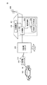
図1は、本発明の実施の形態である車両および受電装置が適用される電力供給システムの構成を示した図である。図1を参照して、電力供給システムは、車両100と、充放電スタンド200と、家屋300に設けられた分電盤302と、分電盤に接続されたHEMS(home energy management system)305と、表示器306を含む。分電盤302には、コンセントなどを介して電気負荷304が接続されている。
FIG. 1 is a diagram showing a configuration of a power supply system to which a vehicle and a power receiving device according to an embodiment of the present invention are applied. Referring to FIG. 1, a power supply system includes a
車両100には、電力ケーブル接続口60(以下、インレット60という)が設けられている。インレット60には、充放電コネクタ220を接続することが可能である。
The
充放電スタンド200は、充放電コネクタ220と分電盤302との間に配置される。充放電スタンドは、車両の駐車スペース近辺に配置されるが、家屋300と駐車スペースが近い場合には、家屋内に配置したり分電盤302と一体化したりしてもよい。
The charging / discharging
常用モード(またはV2Hモード)では、HEMS305は、家屋の電気負荷304で使用される電力および家屋300の太陽電池301の発電電力を考慮した電力の不足と余剰に応じて、車両に家屋から充電を行ない、家屋が車両から電力供給を受ける。また、常用モードの制御は、時間帯によって電気料金が異なる場合に深夜に車両に充電を行ない、電力ピーク時に車両から家屋に電力を供給するような制御が行なわれるものであってもよい。
In the regular mode (or V2H mode), the HEMS 305 charges the vehicle from the house according to the shortage and surplus of power that takes into consideration the power used by the
非常用モードでは、車両100から充放電スタンド200および分電盤302を経由して家屋300に給電が行なわれる。
In the emergency mode, power is supplied from the
車両100から家庭に給電されるのは、たとえば交流100Vまたは200Vの電力であるが、電圧はこれに限られず適宜変更してもよい。
For example, AC 100V or 200V is supplied from the
表示器306は、HEMS305の制御の下、太陽電池301の発電状況や電気負荷の消費電力や車両との接続状態等を表示する。
The
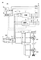
図2は、車両100の構成を示したブロック図である。以下の実施の形態では車両がハイブリッド車両である場合について説明するが、本発明の車両はハイブリッド車両に限定されず、車両は電気自動車や燃料電池自動車であっても良い。
FIG. 2 is a block diagram showing the configuration of
図2を参照して、車両100は、エンジン2と、モータジェネレータMG1,MG2と、動力分割装置4と、駆動輪6とを含む。
Referring to FIG. 2,
車両100は、蓄電装置Bと、システムメインリレーSMRと、コンバータ10と、インバータ21,22と、制御装置50と、HLC(High Level Communication)ユニット104と、電力変換装置30と、コンセント35と、インレット60とをさらに含む。HLCユニット104は、コントロールパイロット信号CPLTに高周波の波形を重畳させて通信を行なうためのユニットである。
車両100は、エンジン2およびモータジェネレータMG2を動力源として走行するハイブリッド車両である。エンジン2およびモータジェネレータMG2が発生した駆動力は、駆動輪6へ伝達される。
エンジン2は、ガソリンエンジンやディーゼルエンジンなどの燃料を燃焼させて動力を出力する内燃機関である。エンジン2は、スロットル開度(吸気量)や燃料供給量、点火時期などの運転状態を制御装置50からの信号によって電気的に制御可能に構成されている。
The
モータジェネレータMG1,MG2は、交流回転電機であり、たとえば、3相交流同期電動機である。モータジェネレータMG1は、エンジン2によって駆動される発電機として用いられるとともに、エンジン2を始動することが可能な回転電機としても用いられる。モータジェネレータMG1が発電することによって得られる電力をモータジェネレータMG2の駆動に用いることができる。また、モータジェネレータMG1が発電することによって得られる電力を車両100に接続される外部機器へ供給することができる。モータジェネレータMG2は、主として車両100の駆動輪6を駆動する回転電機として用いられる。
Motor generators MG1 and MG2 are AC rotating electric machines, for example, three-phase AC synchronous motors. Motor generator MG1 is used as a generator driven by
動力分割装置4は、たとえば、サンギヤ、キャリア、リングギヤの3つの回転軸を有する遊星歯車機構を含む。サンギヤは、モータジェネレータMG1の回転軸に連結される。キャリアは、エンジン2のクランクシャフトに連結される。リングギヤは、駆動軸に連結される。動力分割装置4は、エンジン2の駆動力をモータジェネレータMG1の回転軸に伝達される動力と、駆動軸に伝達される動力とに分割する。駆動軸は、駆動輪6に連結される。また、駆動軸は、モータジェネレータMG2の回転軸にも連結される。
The power split
蓄電装置Bは、充放電可能な直流電源であり、たとえば、ニッケル水素電池、リチウムイオン電池等の二次電池、あるいはキャパシタなどによって構成される。蓄電装置Bは、コンバータ10へ電力を供給し、また、電力回生時には、コンバータ10からの電力によって充電される。
The power storage device B is a chargeable / dischargeable DC power supply, and is configured by, for example, a secondary battery such as a nickel metal hydride battery or a lithium ion battery, or a capacitor. Power storage device B supplies power to
システムメインリレーSMRは、蓄電装置Bとコンバータ10との間に設けられる。システムメインリレーSMRは、蓄電装置Bと電気システムとの電気的な接続/遮断を行なうためのリレーであり、制御装置50によってオン/オフ制御される。
System main relay SMR is provided between power storage device B and
コンバータ10は、蓄電装置Bからの電圧を昇圧して、インバータ21,22へ供給する。また、コンバータ10は、モータジェネレータMG1,MG2で発電されインバータ21,22で整流された電圧を降圧して、蓄電装置Bを充電する。
インバータ21,22は、コンバータ10に対して互いに並列に接続される。インバータ21,22は、制御装置50からの信号によって制御される。インバータ21,22は、コンバータ10から供給される直流電力を交流電力に変換してモータジェネレータMG1,MG2をそれぞれ駆動する。
電力変換装置30は、インレット60に接続される外部機器(図示せず)との間で電力を授受可能に構成される。さらに、電力変換装置30は、車室内に設けられるコンセント35に接続される電機機器へ電力を供給可能に構成される。電力変換装置30は、インレット60と、コンセント35と、システムメインリレーSMRおよびコンバータ間の正極線PL1,負極線NLとに接続される。なお、電力変換装置30は、蓄電装置BおよびシステムメインリレーSMR間の電力線に接続されてもよい。電力変換装置30は、充電器31と、給電用インバータ32と、リレーRY1,RY2とを含む。
The
充電器31は、電力線ACL1,ACL2を介してインレット60に接続され、リレーRY1を介して正極線PL1,負極線NLに接続される。充電器31は、制御装置50からの信号CMDに基づいて、インレット60に接続された外部機器から供給される充電電力を蓄電装置Bの電圧レベルに変換して蓄電装置Bへ出力し、蓄電装置Bを充電する。以下では、外部機器の電力による蓄電装置Bの充電を「外部充電」とも称する。
給電用インバータ32は、入力側が正極線PL1,負極線NLに接続され、出力側がリレーRY2と電力線ACL1,ACL2とを介してインレット60に接続される。さらに、給電用インバータ32は、出力側がコンセント35にも接続される。
給電用インバータ32は、蓄電装置Bの蓄電電力をコンセント35に接続された電機機器へ供給する供給電力に変換し、変換された電力を電機機器へ出力することができる。
The
給電用インバータ32は、常用モードの放電時および非常用モードでは、蓄電装置Bの蓄電電力およびモータジェネレータMG1の発電電力の少なくとも一方を供給電力に変換し、インレット60に接続された充放電コネクタ220を経由して変換された電力を家屋等へ出力することができる。
給電用インバータ32では、制御装置50からの制御信号に基づいて電圧や上限電流が決定される。
In the
本明細書では、蓄電装置Bの電力およびモータジェネレータMG1の発電電力の少なくとも一方を車両から車両外部の負荷や家庭に出力することを「給電」と称する。 In this specification, outputting at least one of the electric power of power storage device B and the electric power generated by motor generator MG1 from the vehicle to a load outside the vehicle or to the home is referred to as “power feeding”.
リレーRY1,RY2は、制御装置50からの信号CMDに基づいて開閉する。リレーRY1は、外部からの充電時に閉成され、外部への給電時に開放される。リレーRY2は、外部からの充電時に開放され、外部への給電時に閉成される。
Relays RY1 and RY2 open and close based on a signal CMD from
インレット60は、車両100の電力を外部負荷や家庭等へ給電するための給電口と、外部電源から車両100を充電するための充電口を兼用可能に構成される。図4で後に説明するように、インレット60は、電力線が接続される端子T9,T10と、信号PISWおよびCPLTを送信する信号線が接続される端子T3,T4とを含む。プロキシメトリディテクション信号PISWは、外部機器に接続されるケーブルのコネクタがインレット60に嵌合されているか否かを車両側で検出するための信号である。コントロールパイロット信号CPLTは、コネクタがインレットに接続されているか否かを示すとともに、電力ケーブルの容量などを通信するための信号である。
The
制御装置50は、アクセル開度やブレーキ踏込量、車両速度等に基づいて駆動輪6に伝達される目標駆動力を決定する。そして、制御装置50は、効率良く目標駆動力を出力することができる運転状態になるように、エンジン2、およびモータジェネレータMG1,MG2を制御する。さらに、制御装置50は、インレット60に外部負荷または外部電源が接続されると、電力変換装置30およびリレーRY1,RY2を制御することによって、外部からの充電と外部への給電を切替えて実行する。
The
図2には、車両100が電力変換装置30を含む例を示したが、このような構成に限定されるものではなく、他の方式で電力を出力する構成の車両であっても良い。たとえば、車両は、インバータ21,22およびモータジェネレータMG1,MG2のステータコイルを用いて、ステータコイルの中性点から電力を出力する構成であっても良い。
Although the example in which the
図3は、図1に示した充放電コネクタ220の外観図である。図3を参照して、充放電コネクタ220は電線部340によって充放電スタンド200に接続されている。また、充放電コネクタ220は、操作ボタン314と、カプラ部315と、係止爪316とを含む。
FIG. 3 is an external view of the charge /
カプラ部315には、複数の接続端子(図示せず)が設けられ、車両100のインレット60に接続されることによって、電線部340内の電力線、接地線および信号線が、車両100側の電力線、接地線および信号線と接続される。
The
本実施の形態においては、操作ボタン314は、充放電コネクタ220の抜け防止のための係止爪316を動作させるためのボタンであり、操作ボタン314の操作に連動して係止爪316が動作する。係止爪316は、抜け防止のための掛止部として働く。
In the present embodiment, the
具体的には、充放電コネクタ220がインレット60に完全に接続されて嵌合状態になると、車両100側の係止爪受け部(図示せず)に係止爪316が引っ掛かり、充放電コネクタ220がインレット60から誤って抜けてしまうことが防止される。そして、操作ボタン314が押下されると、係止爪316が係止爪受け部から外れることによって、充放電コネクタ220をインレット60から引き抜くことが可能となる。
Specifically, when the charging / discharging
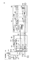
図4は、充放電コネクタ220、充放電スタンド200および家屋300の概略構成を示した図である。
FIG. 4 is a diagram illustrating a schematic configuration of the charge /
図4を参照して、家屋300は、HEMS305と、分電盤302と、表示器306と、電気負荷304とを含む。分電盤302は、HEMS305によって制御され、電力系統400、図示しない太陽電池または車両100から電力を受電し、電気負荷304に供給する。HEMS305は、電力需給状況や車両との接続状態を示す情報を表示器306に表示させる。
Referring to FIG. 4,
充放電スタンド200は、HLCユニット204と、スタンド制御部206と、CPLT発振回路202と、リレー208とを含む。
The charge /
充放電コネクタ220は、端子T1,T2,T5,T7,T8と、操作ボタン314と、係止爪316と、スイッチSW12と、抵抗R11,R12とを含む。
The charge /
抵抗R11と、抵抗R12とは、端子T1と端子T5との間に直列に接続されている。抵抗R12に対してスイッチSW12が並列に接続されている。 The resistor R11 and the resistor R12 are connected in series between the terminal T1 and the terminal T5. A switch SW12 is connected in parallel to the resistor R12.
充放電コネクタ220がインレット60に接続されると、端子T1は、端子T3と接続され、端子T2は、端子T4と接続され、端子T5は、端子T6と接続され、端子T7は、端子T9と接続され、端子T8は、端子T10と接続される。
When the charging / discharging
端子T3は、プロキシメトリディテクション信号PISWの信号線に接続されており、この信号線には、制御装置50の内部においてプルアップ抵抗R10およびCPU51が接続されている。CPU51は、プロキシメトリディテクション信号PISWの電圧を検出することによって、充放電コネクタ220が未接続状態、半嵌合状態、嵌合状態のいずれであるのかを検知することができる。
The terminal T3 is connected to the signal line of the proxy measurement signal PISW, and the pull-up resistor R10 and the CPU 51 are connected to the signal line inside the
端子T4は、コントロールパイロット信号CPLTの信号線に接続されており、この信号線は制御装置50の内部のCPU51に接続されている。
The terminal T4 is connected to the signal line of the control pilot signal CPLT, and this signal line is connected to the CPU 51 inside the
端子T6は、接地電位GNDを与える信号線に接続されている。また、端子T6は、抵抗R13を介して端子T3とも接続されている。端子T9,T10はそれぞれ、電力線ACL1,ACL2に接続されている。 The terminal T6 is connected to a signal line that supplies a ground potential GND. The terminal T6 is also connected to the terminal T3 via the resistor R13. Terminals T9 and T10 are connected to power lines ACL1 and ACL2, respectively.
充放電コネクタ220に内蔵されたスイッチSW12は、操作ボタン314および係止爪316の動作に連動して導通または非導通の状態とされる。充放電コネクタ220とインレット60が嵌合状態の場合には、係止爪316が係止爪受け部に引っ掛かった状態となり、このときスイッチSW12は非導通状態となる。
The switch SW12 built in the charge /
一方、充放電コネクタ220とインレット60が半嵌合状態の場合には、係止爪316が係止爪受け部に押し上げられた状態、すなわち、操作ボタン314が押された状態となり、この状態においては、スイッチSW12は導通状態となる。
On the other hand, when the charging / discharging
このような構成の車両の充電システムにおいては、充電ケーブルのコネクタが車両のインレットに確実に接続されていることが、充電を実行するための条件とされる場合がある。これは、コネクタの接続が緩かったり、ユーザによって充電中にコネクタが取り外されたりした場合に、通電中にコネクタの端子部が離れてしまうことによって端子間でアークが発生し、それによって機器の破損や故障を誘発してしまうことを防止するためである。 In the vehicle charging system having such a configuration, it may be a condition for performing charging that the connector of the charging cable is securely connected to the vehicle inlet. This is because when the connector is loose or the connector is removed by the user during charging, an arc is generated between the terminals due to the separation of the terminal part of the connector during energization, thereby damaging the equipment. This is to prevent the occurrence of failure.
そのため、たとえば、図3に示した充放電コネクタ220のような構成においては、充放電コネクタ220の端子部がインレット60の端子部と接続している状態(すなわち、コントロールパイロット信号CPLTのレベル変化)に加えて、充放電コネクタ220の係止爪316が確実に係止爪受け部に引っ掛かった状態(すなわち、プロキシメトリディテクション信号PISWオン)であることが、充電実行の条件とされる場合がある。このような条件とすることによって、充電中に誤ってコネクタがインレットから外れてしまうことが防止できる。さらに、充電途中でユーザがコネクタを外そうとした場合であっても、係止爪を動作させるためにユーザにより操作ボタンが操作された時点で電力供給が停止されるので、コネクタの端子部がインレットの端子部から離れる際には、すでに非通電状態となっており、アーク等の発生が防止できる。
Therefore, for example, in the configuration like the charge /
一方、このような充電実行条件の場合には、コネクタの接続が不完全であると充電が実行されない。一例を具体的に説明する。 On the other hand, under such charging execution conditions, charging is not executed if the connection of the connector is incomplete. An example will be specifically described.
まず、コネクタを接続し始めた際には、以下(1)〜(3)の順番で端子の接続やコネクタの嵌合が変化していく。 First, when the connector is started to be connected, the connection of the terminal and the fitting of the connector change in the following order (1) to (3).
(1)端子T4と端子T2とが先に接触する。端子T4または端子T2の一方が筒状に形成されており、他方の端子がその中に一部入りこむ。 (1) The terminal T4 and the terminal T2 come into contact first. One of the terminal T4 or the terminal T2 is formed in a cylindrical shape, and the other terminal is partially inserted therein.
(2)上記(1)の状態で係止部316は、インレット60に形成された溝部にはまり込んでおらず、スイッチSW12の状態は、操作部314が押された状態と同じ状態となる。
(2) In the state of (1) above, the locking
(3)上記(2)の際、図3のカプラ部315は、インレットに形成された環状の溝部に一部はまり込んでいる。その結果、充放電コネクタ220は、外観上、インレットに接続されたように見える。
(3) In the case of (2) above, a part of the
上記の(3)の状態が、コネクタの接続が不完全な状態である。なお、完全な状態とは、上記(3)の状態からさらに、コネクタを押し込むことで、係止部316がインレットに形成された溝部にはまり、SW12がOFFとなる。
The state (3) above is an incomplete connector connection. Note that the complete state means that when the connector is further pushed in from the state (3), the locking
したがって、ユーザによるコネクタの接続が不十分であったり、あるいは、端子部の接触不良等が生じていたりすることによって、完全に嵌合状態となっていない場合には充電が実行されず、それにユーザが気付かないままであると、ユーザが、充電が完了したと思って車両を運転しようとした時点では充電が全く行なわれていないという状態が起こり得る。 Therefore, charging is not performed when the connector is not completely engaged due to insufficient connection of the connector by the user, or contact failure of the terminal portion, etc. If the user remains unaware, there may be a situation in which charging is not performed at all when the user tries to drive the vehicle assuming that charging has been completed.
このような場合には、ユーザが、充電ケーブルを取り外したあとに、充電が実行されていないことに気付くことがある。そうすると、車両を使用するときに充電不足であるなどの不都合が生じ得る。 In such a case, the user may notice that charging is not being performed after removing the charging cable. This may cause inconvenience such as insufficient charging when using the vehicle.
そこで、本実施の形態においては、充電ケーブルを用いて外部充電が可能な車両の充電システムにおいて、充電ケーブルのコネクタの接続が不十分である場合には、ユーザに報知する。特に、車両でコネクタの接続状態を報知しても、ユーザが気が付かずに家屋に入ってしまった場合でも、家屋の表示器306でコネクタの半嵌合を報知することにより、ユーザは充電が行なわれていないことを認識することが可能となる。
Therefore, in the present embodiment, in a vehicle charging system capable of external charging using a charging cable, the user is notified when the connection of the connector of the charging cable is insufficient. In particular, even if the connection state of the connector is notified by the vehicle or the user enters the house without being aware of it, the user is charged by notifying the half-fitting of the connector on the
しかし、プロキシメトリディテクション信号PISWは、充放電コネクタ220から充放電スタンド200には送信されていない。したがって、表示器306に充放電コネクタ220の接続状態を表示させるためには、車両側から充放電スタンド200および家屋300側に向けて、充放電コネクタ220の接続状態を送信する必要がある。
However, the proxy measurement signal PISW is not transmitted from the charge /
そこで、本実施の形態では、車両100および充放電スタンド200にそれぞれHLCユニット104,204を設け、コントロールパイロット信号CPLTに、CPU51が検出した充放電コネクタ220の接続状態を示す情報を重畳させて車両から充放電スタンド200に送信する。なお、本実施の形態では、HLCユニットを設けたが、代わりにPLC(Power Line Communication)ユニットを設けて電力線でこの情報を送信してもよく、無線通信ユニットを設けて無線でこの情報を送信してもよい。
Therefore, in the present embodiment,
図5は、車両および家屋で実行される充電開始時の制御を説明するためのフローチャートである。なお、車両からの給電開始時にも同様な制御によってコネクタが半嵌合であることを報知することが可能である。 FIG. 5 is a flowchart for explaining the control at the start of charging executed in the vehicle and the house. It should be noted that it is possible to notify that the connector is half-fitted by the same control at the start of power feeding from the vehicle.
図4、図5を参照して、処理が開始されると、車両では、制御装置50がステップS10において充放電コネクタ220がインレット60に挿入されたか否かを検出する。ステップS210に示すように、ユーザが充放電コネクタ220をインレット60に挿入した場合には、ステップS20に処理が進められ、車両が起動する。
Referring to FIGS. 4 and 5, when the processing is started, in vehicle,
一方、HEMS305は、ステップS110において、スタンド制御部206がコントロールパイロット信号CPLTの電圧を検出することによって充放電コネクタ220の接続があるか否かを検出し、スタンド制御部206からその結果を受信している。ステップS110において車両のインレット60に充放電コネクタ220が接続されたと判断された場合には、ステップS120に処理が進められる。
On the other hand, in step S110, the
ステップS30およびステップS120では、車両と充放電スタンドとの間でコントロールパイロット信号CPLTを用いたHLC通信が試みられ、HLC通信が成立するか否かが判断される。HLC通信が成立しない場合には、ステップS30からステップS10に処理が戻され、ステップS120からステップS110に処理が戻される。 In step S30 and step S120, HLC communication using the control pilot signal CPLT is attempted between the vehicle and the charge / discharge station, and it is determined whether or not the HLC communication is established. If HLC communication is not established, the process returns from step S30 to step S10, and the process returns from step S120 to step S110.
ステップS30およびステップS120においてHLC通信が成立したと判断された場合には、ステップS30からステップS40に処理が進められ、ステップS120からステップS130に処理が進められる。 If it is determined in step S30 and step S120 that HLC communication has been established, the process proceeds from step S30 to step S40, and the process proceeds from step S120 to step S130.
ステップS40では、プロキシメトリディテクション信号PISWの状態、すなわち充放電コネクタ220が完全嵌合か半嵌合かを示す情報を、車両のHLCユニット104から充放電スタンド200のHLCユニット204に送信する。ステップS130では、HLCユニット204がこの情報を受信する。受信した情報は、スタンド制御部206を経由してHEMS305に送信される。
In step S40, the information indicating the state of the proxy detection signal PISW, that is, whether the charge /
車両では、ステップS40の処理が終了すると、ステップS50においてプロキシメトリディテクション信号PISWがOFF(コネクタ半嵌合を示す状態)であるか否かが判断される。プロキシメトリディテクション信号PISWがON状態であればステップS60に処理が進められ通常充電処理が開始される。一方、プロキシメトリディテクション信号PISWがOFF状態であればステップS70に処理が進められ、充電終了となる。 In the vehicle, when the process of step S40 is completed, it is determined in step S50 whether or not the proxy measurement signal PISW is OFF (a state indicating connector half-fitting). If the proxy measurement signal PISW is in the ON state, the process proceeds to step S60 and the normal charging process is started. On the other hand, if the proxy measurement signal PISW is in the OFF state, the process proceeds to step S70, and charging ends.
一方、HEMS305は、ステップS130の処理が終了すると、ステップS140において車両側から受信した情報に基づいて、プロキシメトリディテクション信号PISWがOFF(コネクタ半嵌合を示す状態)であるか否を判断する。プロキシメトリディテクション信号PISWがON状態であればステップS60に処理が進められ通常充電処理が開始される。一方、プロキシメトリディテクション信号PISWがOFF状態であればステップS150に処理が進められ、HEMS350は、表示器306にユーザに対する通知処理を行なわせ、ステップS160において充電処理を終了する。
On the other hand, when the process of step S130 ends, the
ステップS150で通知処理が行なわれると、ステップS310において表示器306にコネクタが半嵌合であることが表示される。たとえば、表示器306に、「充電できません。コネクタをしっかり差し込んでください。」などのメッセージが表示される。なお、音声や警告音などで報知してもよい。この表示などによって、ステップS220においてユーザは充放電コネクタ220が半嵌合であることを認知することができる。そして、ユーザは、必要に応じて車両のところに戻り、充放電コネクタ220を挿入しなおしたりすることができる。
When the notification process is performed in step S150, it is displayed in step S310 that the connector is half-fitted on
図6は、充放電コネクタ220がインレット60に完全に接続された嵌合状態の場合の、充電動作を説明するためのタイムチャートである。図6および後述する図7においては、横軸には時間が示され、縦軸にはパイロット信号CPLTの電位、信号PISWの電位、充電リレーの状態、充電処理の状態および表示器の状態が示される。
FIG. 6 is a time chart for explaining the charging operation in the fitting state in which the charging / discharging
図4および図6を参照して、時刻t10になるまでは、充放電コネクタ220は、車両100に接続されておらず、充放電スタンド200にも電源が入っていない状態である。この状態においては、リレー208はオフの状態であり、パイロット信号CPLTの電位は0Vである。また、プロキシメトリディテクション信号PISWの電位は、V11(>0V)である。
4 and 6, until time t <b> 10, charging / discharging
時刻t10において、充放電スタンド200にも電源がオンされると、CPLT発振回路202がパイロット信号CPLTを発生する。
At time t10, when the power supply to the charge /
なお、この時刻t10では、充放電コネクタ220はインレット60に接続されていない。また、パイロット信号CPLTの電位はV1(たとえば12V)であり、パイロット信号CPLTは非発振状態である。
At this time t10, the charge /
時刻t11において、充放電コネクタ220がインレット60に接続されると、抵抗R11,R12によって、プロキシメトリディテクション信号PISWの電位が低下する。図6においては、充放電コネクタ220とインレット60が嵌合状態であるので、スイッチSW12が開放され、抵抗R11、R12によってプロキシメトリディテクション信号PISWの電位はV13まで低下する。これによって、プロキシメトリディテクション信号PISWがオンとなり、CPU51によって、充放電コネクタ220とインレット60との接続が検出される。
When the charge /
このとき、コントロールパイロット信号CPLTの信号線が接続されるので、図示しないプルダウン抵抗によってパイロット信号CPLTの電位はV2(たとえば9V)に低下する。 At this time, since the signal line of control pilot signal CPLT is connected, the potential of pilot signal CPLT is lowered to V2 (for example, 9 V) by a pull-down resistor (not shown).
時刻t12において、スタンド制御部206によってパイロット信号CPLTの電位が
V2に低下したことが検出される。これに応じて、CPLT発振回路202は、コントロールパイロット信号CPLTを発振させる。
At time t12, the
CPU51は、パイロット信号CPLTが発振されたことを検出すると、パイロット信号CPLTのデューティによって、充電ケーブルの定格電流を検出する。 When detecting that pilot signal CPLT is oscillated, CPU 51 detects the rated current of the charging cable based on the duty of pilot signal CPLT.
そして、CPU51は充電動作を開始するために図示しないプルダウン抵抗を接続することによって、パイロット信号CPLTのハイレベル電位をV3(たとえば6V)に低下させる(図6中の時刻t13以降)。 Then, the CPU 51 connects a pull-down resistor (not shown) to start the charging operation, thereby reducing the high level potential of the pilot signal CPLT to V3 (for example, 6 V) (after time t13 in FIG. 6).
この時に、並行してCPU51は、プロキシメトリディテクション信号PISWのレベルに基づいて検出した充放電コネクタ220とインレット60との接続状態を示す情報を時刻t12〜t13の間にHLCユニット104に送信させる。
At the same time, the CPU 51 transmits information indicating the connection state between the charge /
HEMS305は、コントロールパイロット信号CPLT自体で示されるコネクタ接続状態とHLC通信で送信されたプロキシメトリディテクション信号PISWで判定されたコネクタ接続状態とが両方とも充電に適した状態である場合に、充電可能であると判断し、時刻t14において、リレー208を導通させる。
The
その後、図示しない車両側の電圧センサによって、電力線ACL1,ACL2に交流電圧が検出されると、制御装置50によって、リレーRY1(図2)の接点が閉じられるとともに充電器31(図2)が制御されて、蓄電装置B(図2)の充電が開始される(図4中の時刻t15)。充電処理実行中は、表示器306には何も表示させないか、または充電状況等が表示される。
Thereafter, when an AC voltage is detected on the power lines ACL1 and ACL2 by a vehicle-side voltage sensor (not shown), the
蓄電装置Bの充電が進み、蓄電装置Bが満充電となったことが判定されると、CPU51は、充電処理を停止する(図6中の時刻t16)とともに、図示しないプルダウン抵抗を切り離す(図6中の時刻t17)。これによって、パイロット信号CPLTの電位がV2となり、リレー208が非導通状態とされて(図6中の時刻t18)充電動作が終了する。
When it is determined that the power storage device B is fully charged and the power storage device B is fully charged, the CPU 51 stops the charging process (time t16 in FIG. 6) and disconnects a pull-down resistor (not shown) (FIG. 6). 6 at time t17). Thereby, the potential of pilot signal CPLT becomes V2,
図7は、充放電コネクタ220とインレット60とが半嵌合状態の場合の充電動作について説明するためのタイムチャートである。
FIG. 7 is a time chart for explaining the charging operation when the charge /
図4および図7を参照して、時刻t20において充放電スタンド200が電源オンとされ、時刻t21において、充放電コネクタ220がインレット60に接続される。
Referring to FIGS. 4 and 7, charging / discharging
ところが、図7においては、充放電コネクタ220とインレット60との接続が不十分であるので、スイッチSW12が閉じたままであり、プロキシメトリディテクション信号PISWの電位はV12になる。そうすると、コントロールパイロット信号CPLTはコネクタが接続されたことを示すが、プロキシメトリディテクション信号PISWはオフ(半嵌合)のままとなる。
However, in FIG. 7, since the connection between the charge /
これにより、CPU51は、充放電コネクタ220とインレット60とが半嵌合状態であることを検出する。
Thereby, CPU51 detects that charging / discharging
スタンド制御部206は、時刻t21においてパイロット信号CPLTの電位がV2に低下したことを検出したことに応じて、パイロット信号CPLTを発振状態とする(図7中の時刻t22)。しかしながら、CPU51は、充放電コネクタ220が半嵌合状態であることを検出しているために、図示しないプルダウン抵抗を接続せずパイロット信号CPLTの電位がV3まで低下されないため、リレー208が閉成されず充電操作は開始されない。
The
一方で、CPU51は、時刻t22〜t23の間に、HLCユニット104を用いてスタンド制御部206にプロキシメトリディテクション信号PISWがオフ(すなわち、半嵌合状態)であることを示す情報を送信する。そして、この状態が予め定められた期間だけ継続したことに応答して、CPU51は、半嵌合状態のために充電動作が実行できないと判断し時刻t23において充電を中止する。
On the other hand, during the time t22 to t23, the CPU 51 transmits information indicating that the proxy measurement signal PISW is off (that is, half-fitted state) to the
また、時刻t23においては、HEMS305が半嵌合状態であることを示す情報をスタンド制御部206から得て、表示器306にメッセージを表示する。メッセージは、たとえば「充電できません。コネクタの接続を確認してください。」など、コネクタの接続が異常であり、再接続を促す旨のメッセージであればどのようなものであってもよい。
At time t23, information indicating that the
ユーザは、このメッセージによって、コネクタの接続に問題があることを認識し、時刻t24においてコネクタを一旦引き抜きその後再接続する。再接続後は、図6に示したタイムチャートのように充電が開始される。 The user recognizes that there is a problem with the connection of the connector by this message, and once pulls out the connector at time t24 and then reconnects it. After reconnection, charging is started as shown in the time chart of FIG.
以上説明したように、本実施の形態の充電システムは、コネクタがインレットに半嵌合状態であった場合にも、ユーザに報知することが可能であるので、たとえば、夜間にコネクタをインレットに挿入し、朝気が付くと充電ができていないといった不都合を防ぐことができる。 As described above, the charging system according to the present embodiment can notify the user even when the connector is in a semi-fitted state with the inlet. For example, the connector is inserted into the inlet at night. However, it is possible to prevent inconveniences such as not being able to charge the battery when it is morning.
最後に、再び図2、図4等を参照して本実施の形態について総括する。本実施の形態の充電システムは、蓄電装置Bが搭載されるとともに、蓄電装置Bに充電を行なうための充電接続部(ケーブル接続口またはインレット60)が設けられた車両100と、インレット60に着脱可能とされ、充電が可能な完全嵌合状態および充電が許可されない半嵌合状態でインレット60に接続され得る充放電コネクタ220と、充放電コネクタ220の接続状態が完全嵌合状態か半嵌合状態かを検出する制御装置50と、制御装置50の検出結果に基づいて充放電コネクタ220の接続が半嵌合状態である場合には充放電コネクタ220の接続異常をユーザに報知する表示器306とを備える。
Finally, this embodiment will be summarized with reference to FIGS. 2 and 4 again. In the charging system of the present embodiment, power storage device B is mounted, and
好ましくは、制御装置50は、車両100に設けられ、充放電コネクタ220からインレット60を介して与えられる第1信号および第2信号に基づいて充放電コネクタ220の接続状態を検出する。制御装置50は、第1信号および第2信号のいずれか一方が半嵌合状態を示す場合には、表示器306を起動させる。
Preferably,
より好ましくは、第1信号は、インレット60への充放電コネクタ220の接続の有無を示す信号であり、車両100および充放電スタンド200の双方で検出することが可能である。第2信号は、インレット60への充放電コネクタ220の接続の有無に加えて充放電コネクタ220の接続状態が完全嵌合状態か半嵌合状態かを示す信号であり、車両100では検出することが可能であり、充放電スタンド200では検出することが不可能である。車両の制御装置50は、第2信号の状態を検出した後に、通信によって第2信号の状態を充放電スタンド200に送信する。
More preferably, the first signal is a signal indicating whether or not the charge /
より好ましくは、第1信号は、コントロールパイロット信号CPLTであり、第2信号は、プロキシメトリディテクション信号PISWである。 More preferably, the first signal is a control pilot signal CPLT, and the second signal is a proxy metric detection signal PISW.
より好ましくは、制御装置50は、車両100に配置された制御装置である。充電システムは、家屋300に設けられ、スタンド制御部206を経由して制御装置50と通信することによって第2信号の状態を取得し、取得した第2信号の状態に基づいて表示器306を制御するHEMS305をさらに備える。
More preferably,
より好ましくは、図4に示すように、充放電コネクタ220は、第1端子T1および第2端子T2と、インレット60から充放電コネクタ220が脱落しないように掛止する掛止部316と、ユーザが掛止部316を操作する操作部314とを含む。インレット60は、第1端子T1に対応する第3端子T3と、第2端子T2に対応する第4端子T4とを含む。第1信号は、第1端子部および第3端子部を通る。操作部314は、掛止部316がインレット60に正常に掛止された状態から掛止を解除する操作を行なった場合に第2信号を半嵌合状態を示すように変化させる送信スイッチを兼ねる。第2信号は、第2端子T2および第4端子T4を通じて、インレット60側に伝達される。
More preferably, as shown in FIG. 4, the charging / discharging
この実施の形態は、他の局面では、車両100に関する。車両100は、蓄電装置Bと、蓄電装置Bに車両外部から充電を行なうためのインレット60と、インレット60に着脱可能とされ、充電が可能な完全嵌合状態および充電が許可されない半嵌合状態でインレット60に接続され得る充放電コネクタ220の接続状態が、完全嵌合状態か半嵌合状態かを検出する制御装置50とを備える。制御装置50は、充放電コネクタ220の接続状態が半嵌合状態である場合には、充放電コネクタ220の接続が異常であることをユーザに報知する表示器306を作動させる。
This embodiment relates to
この実施の形態は、さらに他の局面では、蓄電装置Bと、蓄電装置Bに車両外部から充電を行なうためのインレット60と、インレット60に着脱可能とされ、充電が可能な完全嵌合状態および充電が許可されない半嵌合状態でインレット60に接続され得る充放電コネクタ220の接続状態が、完全嵌合状態か半嵌合状態かを検出する制御装置50とを含む車両100に充電を行なう充電設備である充放電スタンド200および家屋300を開示する。充放電スタンド200および家屋300は、制御装置50と通信を行なって、充放電コネクタ220の接続状態を取得するHEMS305と、HEMS305によって制御され、充放電コネクタ220の接続状態が半嵌合状態である場合には、充放電コネクタ220の接続が異常であることをユーザに報知する表示器306とを備える。
In yet another aspect, this embodiment is a power storage device B, an
以上の構成を採用することにより、ユーザが半嵌合状態で気が付かないまま時間が経過してしまうのを防ぐことができる。 By adopting the above configuration, it is possible to prevent the user from lapse of time without noticing in the half-fitted state.
なお、本実施の形態では、充電時の半嵌合状態を報知することを例示したが、車両から家屋に給電する際も同様な構成で半嵌合状態を報知することが可能である。 In the present embodiment, it is exemplified that the half-fitted state at the time of charging is notified. However, even when power is supplied from the vehicle to the house, the half-fitted state can be notified with the same configuration.
また、本実施の形態では、通信手段として、コントロールパイロット信号に信号を重畳させるHLC通信を使用することを例示したが、半嵌合状態を車両から充電設備側に通信する通信手段としては、電力線に信号を重畳するPLC通信を使用しても良く、また無線通信などを使用しても良い。 Further, in the present embodiment, the use of HLC communication that superimposes the signal on the control pilot signal is exemplified as the communication means. However, as the communication means for communicating the half-fitted state from the vehicle to the charging facility side, the power line PLC communication that superimposes a signal on the wireless communication or wireless communication may be used.
今回開示された実施の形態は、すべての点で例示であって制限的なものではないと考えられるべきである。本発明の範囲は、上記した実施の形態の説明ではなくて特許請求の範囲によって示され、特許請求の範囲と均等の意味および範囲内でのすべての変更が含まれることが意図される。 The embodiment disclosed this time should be considered as illustrative in all points and not restrictive. The scope of the present invention is shown not by the above description of the embodiments but by the scope of claims for patent, and is intended to include meanings equivalent to the scope of claims for patent and all modifications within the scope.
2 エンジン、4 動力分割装置、6 駆動輪、10 コンバータ、21,22 インバータ、30 電力変換装置、31 充電器、32 給電用インバータ、35 コンセント、50 制御装置、60 インレット、100 車両、104,204 HLCユニット、200 充放電スタンド、202 発振回路、206 スタンド制御部、208,RY1,RY2 リレー、220 充放電コネクタ、300 家屋、301 太陽電池、302 分電盤、304 電気負荷、306 表示器、314 操作ボタン、315 カプラ部、316 係止爪、340 電線部、400 電力系統、ACL1,ACL2 電力線、B 蓄電装置、MG1,MG2 モータジェネレータ、NL 負極線、PISW プロキシメトリディテクション信号、PL1 正極線、R10〜R12 抵抗、SMR システムメインリレー、SW12 スイッチ、T1〜T10 端子。
2 engines, 4 power split devices, 6 drive wheels, 10 converters, 21 and 22 inverters, 30 power converters, 31 chargers, 32 power supply inverters, 35 outlets, 50 control devices, 60 inlets, 100 vehicles, 104, 204 HLC unit, 200 charge / discharge stand, 202 oscillation circuit, 206 stand control unit, 208, RY1, RY2 relay, 220 charge / discharge connector, 300 house, 301 solar cell, 302 distribution board, 304 electrical load, 306 display, 314 Operation button, 315 Coupler part, 316 Locking claw, 340 Electric wire part, 400 Power system, ACL1, ACL2 Power line, B Power storage device, MG1, MG2 Motor generator, NL Negative electrode line, PISW Proxy-metric detection signal, PL1 Positive electrode line,
Claims (7)
前記車両の前記充電接続部を介して前記蓄電装置に充電を行なう充電設備と、
前記充電接続部に着脱可能とされ、充電が可能な完全嵌合状態および充電が許可されない半嵌合状態で前記充電接続部に接続され得る接続器と、
前記車両に設けられ、前記接続器の接続状態が前記完全嵌合状態か前記半嵌合状態かを検出する検出部と、
前記検出部の検出結果に基づいて前記接続器の接続が前記半嵌合状態である場合には前記接続器の接続異常をユーザに報知する報知部とを備え、
前記検出部は、車両に設けられ、前記接続器から前記充電接続部を介して与えられる第1信号および第2信号に基づいて前記接続器の接続状態を検出し、
前記第1信号は、前記充電接続部への前記接続器の接続の有無を示す信号であり、前記車両および前記充電設備の双方で検出することが可能であり、
前記第2信号は、前記充電接続部への前記接続器の接続の有無に加えて前記接続器の接続状態が前記完全嵌合状態か前記半嵌合状態かを示す信号であり、車両では検出することが可能であり、前記充電設備では検出することが不可能であり、
前記検出部は、前記第2信号の状態が前記半嵌合状態を検出した場合に、通信によって前記第2信号の状態を前記充電設備に送信することによって前記報知部を起動させる、充電システム。 A vehicle equipped with a power storage device and provided with a charge connection for charging the power storage device;
A charging facility for charging the power storage device via the charging connection portion of the vehicle;
Is detachable before Symbol charging connecting portion, and a connector for a semi-fitted state in which charging is completely fitted state and charging can be not allowed may be connected to the charging connection unit,
A detection unit provided in the vehicle for detecting whether the connection state of the connector is the fully-fitted state or the half-fitted state;
When the connection of the connector is in the half-fitted state based on the detection result of the detector, a notification unit that notifies the user of a connection abnormality of the connector,
The detection unit is provided in a vehicle, detects a connection state of the connector based on a first signal and a second signal given from the connector via the charging connection unit,
The first signal is a signal indicating whether or not the connector is connected to the charging connection portion, and can be detected by both the vehicle and the charging facility,
The second signal is a signal indicating whether the connection state of the connector is in the fully-fitted state or the half-fitted state in addition to the presence / absence of connection of the connector to the charging connection part. Can not be detected by the charging facility,
The said detection part is a charging system which starts the said alerting | reporting part by transmitting the state of the said 2nd signal to the said charging equipment by communication, when the state of the said 2nd signal detects the said half-fitted state.
前記検出部は、前記HLCユニットを用いた通信によって前記第2信号の状態を前記充電設備に送信する、請求項1に記載の充電システム。The charging system according to claim 1, wherein the detection unit transmits the state of the second signal to the charging facility by communication using the HLC unit.
前記第2信号は、プロキシメトリディテクション信号である、請求項1に記載の充電システム。 The first signal is a control pilot signal;
The charging system according to claim 1, wherein the second signal is a proxy detection signal.
家屋に設けられ、前記制御装置と通信することによって前記第2信号の状態を取得し、取得した前記第2信号の状態に基づいて前記報知部を制御するHEMSをさらに備える、請求項1に記載の充電システム。 The detection unit is a control device arranged in the vehicle,
The HEMS which is provided in a house, acquires the state of the 2nd signal by communicating with the control device, and controls the informing part based on the acquired state of the 2nd signal. Charging system.
第1端子部および第2端子部と、
前記充電接続部から前記接続器が脱落しないように掛止する掛止部と、
前記ユーザが前記掛止部を操作する操作部とを含み、
前記充電接続部は、
前記第1端子部に対応する第3端子部と、
前記第2端子部に対応する第4端子部とを含み、
前記第1信号は、前記第1端子部および前記第3端子部を通り、
前記操作部は、前記掛止部が前記充電接続部に正常に掛止された状態から掛止を解除する操作を行なった場合に前記第2信号を前記半嵌合状態を示すように変化させる送信スイッチを兼ね、
前記第2信号は、前記第2端子部および前記第4端子部を通じて、前記充電接続部側に伝達される、請求項1に記載の充電システム。 The connector is
A first terminal portion and a second terminal portion;
A latching part for latching so that the connector does not fall off from the charging connection part;
An operation unit for the user to operate the latch unit;
The charging connection is
A third terminal portion corresponding to the first terminal portion;
A fourth terminal portion corresponding to the second terminal portion,
The first signal passes through the first terminal portion and the third terminal portion,
The operation unit changes the second signal to indicate the half-fitted state when an operation for releasing the latch from a state in which the latch unit is normally latched to the charging connection unit is performed. Also serves as a transmission switch,
2. The charging system according to claim 1, wherein the second signal is transmitted to the charging connection portion through the second terminal portion and the fourth terminal portion.
前記蓄電装置に車両外部から充電を行なうための充電接続部と、
前記充電接続部に着脱可能とされ、充電が可能な完全嵌合状態および充電が許可されない半嵌合状態で前記充電接続部に接続され得る接続器の接続状態が、前記完全嵌合状態か前記半嵌合状態かを検出する制御装置とを備え、
前記制御装置は、前記接続器の接続状態が前記半嵌合状態である場合には、前記接続器の接続が異常であることをユーザに報知する報知部を作動させ、
前記接続器から前記充電接続部を介して与えられる第1信号および第2信号に基づいて前記接続器の接続状態を検出し、
前記第1信号は、前記充電接続部への前記接続器の接続の有無を示す信号であり、車両および充電設備の双方で検出することが可能であり、
前記第2信号は、前記充電接続部への前記接続器の接続の有無に加えて前記接続器の接続状態が前記完全嵌合状態か前記半嵌合状態かを示す信号であり、車両では検出することが可能であり、前記充電設備では検出することが不可能であり、
前記制御装置は、前記第2信号が前記半嵌合状態を示す場合には、通信によって前記第2信号の状態を前記充電設備に送信することによって前記報知部を起動させる、車両。 A power storage device;
A charging connection for charging the power storage device from outside the vehicle;
The connection state of the connector that can be connected to the charging connection part in a fully-fitted state that can be attached to and detached from the charging connection part and that can be charged, and a half-fitted state that does not allow charging, A control device for detecting whether it is in a half-fitted state,
When the connection state of the connector is the half-fitted state, the control device operates a notification unit that notifies the user that the connection of the connector is abnormal,
Detecting a connection state of the connector based on a first signal and a second signal given from the connector via the charging connection unit;
The first signal is a signal indicating whether or not the connector is connected to the charging connection portion, and can be detected by both the vehicle and the charging facility,
The second signal is a signal indicating whether the connection state of the connector is in the fully-fitted state or the half-fitted state in addition to the presence / absence of connection of the connector to the charging connection part. Can not be detected by the charging facility,
Said control device, said second signal when said indicating the half-fitting state, activating the notification unit by sending a status of the second signal to the charging facility by communication, a vehicle.
前記制御装置と通信を行なって、前記接続器の接続状態を取得するHEMSと、
前記HEMSによって制御され、前記接続器の接続状態が前記半嵌合状態である場合には、前記接続器の接続が異常であることをユーザに報知する報知部とを備え、
前記制御装置は、前記接続器から前記充電接続部を介して与えられる第1信号および第2信号に基づいて前記接続器の接続状態を検出し、
前記第1信号は、前記充電接続部への前記接続器の接続の有無を示す信号であり、車両および前記充電設備の双方で検出することが可能であり、
前記第2信号は、前記充電接続部への前記接続器の接続の有無に加えて前記接続器の接続状態が前記完全嵌合状態か前記半嵌合状態かを示す信号であり、車両では検出することが可能であり、前記充電設備では検出することが不可能であり、
前記報知部は、前記制御装置が、前記第2信号が前記半嵌合状態を示す場合に通信によって前記第2信号の状態を前記充電設備に送信したことに応じて起動する、充電設備。 The power storage device, a charging connection portion for charging the power storage device from the outside of the vehicle, the detachable connection to the charging connection portion, and a fully fitted state where charging is possible and a semi-fitted state where charging is not allowed A charging facility for charging a vehicle including a control device that detects whether a connection state of a connector that can be connected to a charging connection part is the fully-fitted state or the half-fitted state,
HEMS which communicates with the control device and acquires the connection state of the connector;
A control unit that is controlled by the HEMS and that notifies the user that the connection of the connector is abnormal when the connection state of the connector is the half-fitted state;
The control device detects a connection state of the connector based on a first signal and a second signal given from the connector via the charging connection unit,
The first signal is a signal indicating whether or not the connector is connected to the charging connection portion, and can be detected by both the vehicle and the charging facility,
The second signal is a signal indicating whether the connection state of the connector is in the fully-fitted state or the half-fitted state in addition to the presence / absence of connection of the connector to the charging connection part. Can not be detected by the charging facility,
The notification unit, wherein the controller is activated in response to said second signal transmits the state of the second signal by the communication to indicate the half-fitted state to the charging equipment, charging facilities.
Priority Applications (5)
| Application Number | Priority Date | Filing Date | Title |
|---|---|---|---|
| JP2013169632A JP6142729B2 (en) | 2013-08-19 | 2013-08-19 | Charging system, vehicle and charging equipment |
| US14/912,696 US9889758B2 (en) | 2013-08-19 | 2014-08-12 | Charging system, vehicle, and charging facility |
| PCT/IB2014/001509 WO2015025201A2 (en) | 2013-08-19 | 2014-08-12 | Charging system, vehicle, and charging facility |
| EP14777142.2A EP3036128B1 (en) | 2013-08-19 | 2014-08-12 | Charging system, vehicle, and charging facility |
| CN201480045737.3A CN105473372B (en) | 2013-08-19 | 2014-08-12 | Charging system, vehicle and charging equipment |
Applications Claiming Priority (1)
| Application Number | Priority Date | Filing Date | Title |
|---|---|---|---|
| JP2013169632A JP6142729B2 (en) | 2013-08-19 | 2013-08-19 | Charging system, vehicle and charging equipment |
Publications (3)
| Publication Number | Publication Date |
|---|---|
| JP2015039267A JP2015039267A (en) | 2015-02-26 |
| JP2015039267A5 JP2015039267A5 (en) | 2016-03-24 |
| JP6142729B2 true JP6142729B2 (en) | 2017-06-07 |
Family
ID=51627318
Family Applications (1)
| Application Number | Title | Priority Date | Filing Date |
|---|---|---|---|
| JP2013169632A Active JP6142729B2 (en) | 2013-08-19 | 2013-08-19 | Charging system, vehicle and charging equipment |
Country Status (5)
| Country | Link |
|---|---|
| US (1) | US9889758B2 (en) |
| EP (1) | EP3036128B1 (en) |
| JP (1) | JP6142729B2 (en) |
| CN (1) | CN105473372B (en) |
| WO (1) | WO2015025201A2 (en) |
Families Citing this family (25)
| Publication number | Priority date | Publication date | Assignee | Title |
|---|---|---|---|---|
| US9597969B2 (en) * | 2013-08-06 | 2017-03-21 | Amres Network Coalition, LLC | Systems and methods for providing in-road electric conductivity boxes and on-vehicle descent and pivot contacts for vehicles |
| SE538806C2 (en) * | 2015-02-18 | 2016-12-06 | Scania Cv Ab | Method and control system for charging a vehicle |
| SE538693C2 (en) | 2015-02-18 | 2016-10-18 | Scania Cv Ab | Method and control system for charging a hybrid vehicle |
| JP6504137B2 (en) * | 2016-09-05 | 2019-04-24 | トヨタ自動車株式会社 | Charging device and control method of charging device |
| DE102016225143B4 (en) | 2016-12-15 | 2020-03-12 | Audi Ag | Motor vehicle and charging device with this motor vehicle |
| WO2018145726A1 (en) * | 2017-02-07 | 2018-08-16 | Volkswagen Aktiengesellschaft | Vehicle-sided conductive charging device, electric vehicle and method for operating vehicle-sided conductive charging device |
| KR102001562B1 (en) * | 2017-04-28 | 2019-07-19 | 한국전력공사 | Apparatus and method for controling multi communication of electric vehicle charger |
| CN111032421A (en) * | 2017-06-28 | 2020-04-17 | 特洛伊能源有限公司 | Device and system for connecting an electric vehicle to an electric power network and method of use |
| WO2019052961A1 (en) * | 2017-09-12 | 2019-03-21 | easE-Link GmbH | Vehicle contact unit, ground contact unit, vehicle coupling system and method for checking the contacting and the assignment of contact points |
| CN111344187A (en) * | 2017-09-12 | 2020-06-26 | 易链接有限责任公司 | Vehicle connection device, ground contact unit, vehicle coupling system and method for automatically and electrically connecting a vehicle contact unit to a ground contact unit |
| JP6984323B2 (en) * | 2017-11-01 | 2021-12-17 | トヨタ自動車株式会社 | Information provision system and server |
| JP2019129671A (en) | 2018-01-26 | 2019-08-01 | トヨタ自動車株式会社 | Vehicle, battery charger and charging system including the same, and method for diagnosis of abnormality of battery charger |
| US10938211B2 (en) * | 2018-11-21 | 2021-03-02 | Ford Global Technologies, Llc | Integrated vehicle-to-home energy management system |
| JP6689428B2 (en) * | 2019-03-26 | 2020-04-28 | 三菱電機株式会社 | Charger |
| JP7268566B2 (en) * | 2019-10-09 | 2023-05-08 | トヨタ自動車株式会社 | vehicle |
| JP7200908B2 (en) | 2019-10-30 | 2023-01-10 | トヨタ自動車株式会社 | Notification control device, moving body, and electric power system |
| FR3114056B1 (en) * | 2020-09-14 | 2022-08-19 | Renault | Electric vehicle and switching device for a household electrical network |
| CN112477656A (en) * | 2020-12-18 | 2021-03-12 | 蔚来汽车科技(安徽)有限公司 | DC charging gun and charging pile |
| CN114825397A (en) * | 2021-01-27 | 2022-07-29 | 台达电子工业股份有限公司 | Bidirectional AC charging device and operation method thereof |
| GB202104493D0 (en) * | 2021-03-30 | 2021-05-12 | Trojan Energy Ltd | Apparatus and system for connecting electric vehicles to an electrical network and method of use |
| EP4119386A1 (en) * | 2021-07-14 | 2023-01-18 | Vestel Elektronik Sanayi ve Ticaret A.S. | Method and system for removably connecting a connector of a charging cable to a charging socket for charging an electrical vehicle |
| IT202100027797A1 (en) * | 2021-10-29 | 2023-04-29 | Rmg Ind Advance S R L | VEHICLE AND COLUMN FOR DISTRIBUTED ELECTRIC CHARGING OF ELECTRIC CAR BATTERIES AND RELATED SAFETY SYSTEM |
| US11613184B1 (en) | 2021-10-31 | 2023-03-28 | Beta Air, Llc | Systems and methods for disabling an electric vehicle during charging |
| DE202022103788U1 (en) | 2022-04-04 | 2023-07-06 | Easelink Gmbh | System for checking a ground contact unit and electrical charging infrastructure |
| JP2024048130A (en) * | 2022-09-27 | 2024-04-08 | トヨタ自動車株式会社 | vehicle |
Family Cites Families (14)
| Publication number | Priority date | Publication date | Assignee | Title |
|---|---|---|---|---|
| JP4285578B1 (en) * | 2008-01-15 | 2009-06-24 | トヨタ自動車株式会社 | Vehicle charging device |
| JP4380776B1 (en) * | 2008-07-25 | 2009-12-09 | トヨタ自動車株式会社 | Charge / discharge system and electric vehicle |
| US20110004358A1 (en) * | 2009-03-31 | 2011-01-06 | Gridpoint, Inc. | Systems and methods for electric vehicle power flow management |
| JP2011072081A (en) * | 2009-09-24 | 2011-04-07 | Fujitsu Ten Ltd | Control unit and control method of plug-in vehicle |
| KR101760632B1 (en) * | 2010-05-19 | 2017-07-21 | 퀄컴 인코포레이티드 | Adaptive wireless energy transfer system |
| JP5551098B2 (en) * | 2011-03-14 | 2014-07-16 | トヨタ自動車株式会社 | Energy management system |
| JP5773253B2 (en) * | 2011-03-30 | 2015-09-02 | シンフォニアテクノロジー株式会社 | Charging equipment |
| JP2013003779A (en) * | 2011-06-15 | 2013-01-07 | Toyota Home Kk | Crime prevention system for vehicle |
| US8350526B2 (en) * | 2011-07-25 | 2013-01-08 | Lightening Energy | Station for rapidly charging an electric vehicle battery |
| JP5170482B2 (en) | 2011-08-30 | 2013-03-27 | トヨタ自動車株式会社 | Method for identifying operation mode in charging / power supply system between vehicle and outside, and identification device for identifying operation mode of the system by the identification method |
| JP2013081324A (en) | 2011-10-05 | 2013-05-02 | Toyota Motor Corp | Vehicle charging system and vehicle charging method |
| JP5710440B2 (en) | 2011-10-06 | 2015-04-30 | トヨタ自動車株式会社 | Vehicle charging system and vehicle charging method |
| JP5234159B2 (en) * | 2011-10-31 | 2013-07-10 | トヨタ自動車株式会社 | A vehicle including a power storage unit capable of discharging (power feeding) to an external load, a discharge system including the vehicle and a power cable, a discharge control method for the power storage unit, and a device outside the vehicle used in the discharge system. |
| US9216655B2 (en) * | 2011-11-17 | 2015-12-22 | Toyota Jidosha Kabushiki Kaisha | Vehicle and power supply system |
-
2013
- 2013-08-19 JP JP2013169632A patent/JP6142729B2/en active Active
-
2014
- 2014-08-12 US US14/912,696 patent/US9889758B2/en active Active
- 2014-08-12 WO PCT/IB2014/001509 patent/WO2015025201A2/en active Application Filing
- 2014-08-12 CN CN201480045737.3A patent/CN105473372B/en active Active
- 2014-08-12 EP EP14777142.2A patent/EP3036128B1/en active Active
Also Published As
| Publication number | Publication date |
|---|---|
| WO2015025201A2 (en) | 2015-02-26 |
| CN105473372A (en) | 2016-04-06 |
| EP3036128B1 (en) | 2019-10-02 |
| US9889758B2 (en) | 2018-02-13 |
| EP3036128A2 (en) | 2016-06-29 |
| US20160207409A1 (en) | 2016-07-21 |
| CN105473372B (en) | 2018-01-26 |
| WO2015025201A3 (en) | 2015-05-14 |
| JP2015039267A (en) | 2015-02-26 |
Similar Documents
| Publication | Publication Date | Title |
|---|---|---|
| JP6142729B2 (en) | Charging system, vehicle and charging equipment | |
| US9434257B2 (en) | Power supply connector, vehicle and control method for vehicle | |
| US9090169B2 (en) | Adapter and vehicle for performing power feeding using adapter | |
| JP5735050B2 (en) | Vehicle and power receiving device | |
| US8768533B2 (en) | Vehicle, communication system, and communication device | |
| US8179086B2 (en) | Control apparatus and control method | |
| CN102803001B (en) | Charge controlling device for electric vehicle | |
| JP5234159B2 (en) | A vehicle including a power storage unit capable of discharging (power feeding) to an external load, a discharge system including the vehicle and a power cable, a discharge control method for the power storage unit, and a device outside the vehicle used in the discharge system. | |
| US8772961B2 (en) | Communication device, communication system, and vehicle | |
| JP6044460B2 (en) | Vehicle power supply | |
| JPWO2011064856A1 (en) | Charger | |
| JP2012162176A (en) | Vehicle and vehicle control method | |
| EP3875304A1 (en) | Electrically powered vehicle and method for controlling electrically powered vehicle | |
| JP2015096016A (en) | Charge/discharge system | |
| CN104584373A (en) | Vehicle power control system and power control method | |
| US9108522B2 (en) | Vehicle-mounted controller | |
| JP2011205840A (en) | Charger for vehicle | |
| JP2013165610A (en) | Vehicle external control device applied to vehicle equipped with power storage part and charge/discharge system including vehicle external control device, vehicle, and power cable | |
| WO2012164681A1 (en) | Vehicle and method for controlling vehicle | |
| JP6003776B2 (en) | Power supply system, vehicle including the same, and control method of power supply system | |
| JP6003775B2 (en) | Power supply system, vehicle including the same, and control method of power supply system | |
| JP6024573B2 (en) | Power connector and power supply system |
Legal Events
| Date | Code | Title | Description |
|---|---|---|---|
| A521 | Request for written amendment filed |
Free format text: JAPANESE INTERMEDIATE CODE: A523 Effective date: 20160201 |
|
| A621 | Written request for application examination |
Free format text: JAPANESE INTERMEDIATE CODE: A621 Effective date: 20160201 |
|
| A977 | Report on retrieval |
Free format text: JAPANESE INTERMEDIATE CODE: A971007 Effective date: 20161031 |
|
| A131 | Notification of reasons for refusal |
Free format text: JAPANESE INTERMEDIATE CODE: A131 Effective date: 20161108 |
|
| A521 | Request for written amendment filed |
Free format text: JAPANESE INTERMEDIATE CODE: A523 Effective date: 20161222 |
|
| A131 | Notification of reasons for refusal |
Free format text: JAPANESE INTERMEDIATE CODE: A131 Effective date: 20170124 |
|
| A521 | Request for written amendment filed |
Free format text: JAPANESE INTERMEDIATE CODE: A523 Effective date: 20170126 |
|
| TRDD | Decision of grant or rejection written | ||
| A01 | Written decision to grant a patent or to grant a registration (utility model) |
Free format text: JAPANESE INTERMEDIATE CODE: A01 Effective date: 20170411 |
|
| A61 | First payment of annual fees (during grant procedure) |
Free format text: JAPANESE INTERMEDIATE CODE: A61 Effective date: 20170424 |
|
| R151 | Written notification of patent or utility model registration |
Ref document number: 6142729 Country of ref document: JP Free format text: JAPANESE INTERMEDIATE CODE: R151 |