EP2672234B1 - Système et procédé de surveillance d'un composant lors de sa production ainsi que pendant son fonctionnement - Google Patents
Système et procédé de surveillance d'un composant lors de sa production ainsi que pendant son fonctionnement Download PDFInfo
- Publication number
- EP2672234B1 EP2672234B1 EP12170869.7A EP12170869A EP2672234B1 EP 2672234 B1 EP2672234 B1 EP 2672234B1 EP 12170869 A EP12170869 A EP 12170869A EP 2672234 B1 EP2672234 B1 EP 2672234B1
- Authority
- EP
- European Patent Office
- Prior art keywords
- optical fibre
- matrix material
- composite component
- optical
- component
- Prior art date
- Legal status (The legal status is an assumption and is not a legal conclusion. Google has not performed a legal analysis and makes no representation as to the accuracy of the status listed.)
- Active
Links
- 238000012544 monitoring process Methods 0.000 title claims description 61
- 238000004519 manufacturing process Methods 0.000 title claims description 46
- 238000000034 method Methods 0.000 title claims description 45
- 239000013307 optical fiber Substances 0.000 claims description 106
- 239000011159 matrix material Substances 0.000 claims description 100
- 238000000465 moulding Methods 0.000 claims description 97
- 239000002131 composite material Substances 0.000 claims description 95
- 230000003287 optical effect Effects 0.000 claims description 66
- 239000007788 liquid Substances 0.000 claims description 24
- 230000003014 reinforcing effect Effects 0.000 claims description 21
- 238000001069 Raman spectroscopy Methods 0.000 claims description 6
- WYTGDNHDOZPMIW-RCBQFDQVSA-N alstonine Natural products C1=CC2=C3C=CC=CC3=NC2=C2N1C[C@H]1[C@H](C)OC=C(C(=O)OC)[C@H]1C2 WYTGDNHDOZPMIW-RCBQFDQVSA-N 0.000 claims description 5
- 238000004891 communication Methods 0.000 claims description 5
- 238000010276 construction Methods 0.000 claims description 5
- 239000000463 material Substances 0.000 description 56
- 238000003860 storage Methods 0.000 description 37
- 238000010438 heat treatment Methods 0.000 description 18
- 239000000835 fiber Substances 0.000 description 16
- 229920005989 resin Polymers 0.000 description 14
- 239000011347 resin Substances 0.000 description 14
- 238000005259 measurement Methods 0.000 description 11
- 230000008859 change Effects 0.000 description 9
- 238000001514 detection method Methods 0.000 description 7
- 230000033001 locomotion Effects 0.000 description 7
- 239000011208 reinforced composite material Substances 0.000 description 7
- 239000012528 membrane Substances 0.000 description 6
- 229920002430 Fibre-reinforced plastic Polymers 0.000 description 5
- 239000011151 fibre-reinforced plastic Substances 0.000 description 5
- 230000008901 benefit Effects 0.000 description 4
- 238000011156 evaluation Methods 0.000 description 4
- 238000001802 infusion Methods 0.000 description 4
- 238000002347 injection Methods 0.000 description 4
- 239000007924 injection Substances 0.000 description 4
- 238000004458 analytical method Methods 0.000 description 3
- 238000010586 diagram Methods 0.000 description 3
- 239000003822 epoxy resin Substances 0.000 description 3
- 229920000647 polyepoxide Polymers 0.000 description 3
- 230000008569 process Effects 0.000 description 3
- 238000005452 bending Methods 0.000 description 2
- 238000001816 cooling Methods 0.000 description 2
- 230000032798 delamination Effects 0.000 description 2
- 230000001419 dependent effect Effects 0.000 description 2
- 230000000694 effects Effects 0.000 description 2
- 239000004744 fabric Substances 0.000 description 2
- 239000006260 foam Substances 0.000 description 2
- 230000014509 gene expression Effects 0.000 description 2
- 239000003365 glass fiber Substances 0.000 description 2
- 239000005304 optical glass Substances 0.000 description 2
- 229920000642 polymer Polymers 0.000 description 2
- 230000008054 signal transmission Effects 0.000 description 2
- OKTJSMMVPCPJKN-UHFFFAOYSA-N Carbon Chemical compound [C] OKTJSMMVPCPJKN-UHFFFAOYSA-N 0.000 description 1
- 230000006978 adaptation Effects 0.000 description 1
- 230000004075 alteration Effects 0.000 description 1
- 230000005540 biological transmission Effects 0.000 description 1
- 229910052799 carbon Inorganic materials 0.000 description 1
- 238000006243 chemical reaction Methods 0.000 description 1
- 230000006835 compression Effects 0.000 description 1
- 238000007906 compression Methods 0.000 description 1
- 230000007797 corrosion Effects 0.000 description 1
- 238000005260 corrosion Methods 0.000 description 1
- 238000005336 cracking Methods 0.000 description 1
- 230000003247 decreasing effect Effects 0.000 description 1
- 238000009826 distribution Methods 0.000 description 1
- 239000006261 foam material Substances 0.000 description 1
- 230000006870 function Effects 0.000 description 1
- 239000007789 gas Substances 0.000 description 1
- 230000036541 health Effects 0.000 description 1
- 230000001771 impaired effect Effects 0.000 description 1
- 230000001788 irregular Effects 0.000 description 1
- 239000011344 liquid material Substances 0.000 description 1
- 239000004033 plastic Substances 0.000 description 1
- 229920003023 plastic Polymers 0.000 description 1
- 238000006116 polymerization reaction Methods 0.000 description 1
- 229920007790 polymethacrylimide foam Polymers 0.000 description 1
- 230000001902 propagating effect Effects 0.000 description 1
- 238000000275 quality assurance Methods 0.000 description 1
- 230000002787 reinforcement Effects 0.000 description 1
- 229920006395 saturated elastomer Polymers 0.000 description 1
- 239000004065 semiconductor Substances 0.000 description 1
- 239000007787 solid Substances 0.000 description 1
- 230000000007 visual effect Effects 0.000 description 1
- 238000011179 visual inspection Methods 0.000 description 1
Images

Classifications
-
- B—PERFORMING OPERATIONS; TRANSPORTING
- B29—WORKING OF PLASTICS; WORKING OF SUBSTANCES IN A PLASTIC STATE IN GENERAL
- B29C—SHAPING OR JOINING OF PLASTICS; SHAPING OF MATERIAL IN A PLASTIC STATE, NOT OTHERWISE PROVIDED FOR; AFTER-TREATMENT OF THE SHAPED PRODUCTS, e.g. REPAIRING
- B29C70/00—Shaping composites, i.e. plastics material comprising reinforcements, fillers or preformed parts, e.g. inserts
- B29C70/04—Shaping composites, i.e. plastics material comprising reinforcements, fillers or preformed parts, e.g. inserts comprising reinforcements only, e.g. self-reinforcing plastics
- B29C70/28—Shaping operations therefor
- B29C70/54—Component parts, details or accessories; Auxiliary operations, e.g. feeding or storage of prepregs or SMC after impregnation or during ageing
- B29C70/546—Measures for feeding or distributing the matrix material in the reinforcing structure
-
- G—PHYSICS
- G01—MEASURING; TESTING
- G01D—MEASURING NOT SPECIALLY ADAPTED FOR A SPECIFIC VARIABLE; ARRANGEMENTS FOR MEASURING TWO OR MORE VARIABLES NOT COVERED IN A SINGLE OTHER SUBCLASS; TARIFF METERING APPARATUS; MEASURING OR TESTING NOT OTHERWISE PROVIDED FOR
- G01D5/00—Mechanical means for transferring the output of a sensing member; Means for converting the output of a sensing member to another variable where the form or nature of the sensing member does not constrain the means for converting; Transducers not specially adapted for a specific variable
- G01D5/26—Mechanical means for transferring the output of a sensing member; Means for converting the output of a sensing member to another variable where the form or nature of the sensing member does not constrain the means for converting; Transducers not specially adapted for a specific variable characterised by optical transfer means, i.e. using infrared, visible, or ultraviolet light
- G01D5/32—Mechanical means for transferring the output of a sensing member; Means for converting the output of a sensing member to another variable where the form or nature of the sensing member does not constrain the means for converting; Transducers not specially adapted for a specific variable characterised by optical transfer means, i.e. using infrared, visible, or ultraviolet light with attenuation or whole or partial obturation of beams of light
- G01D5/34—Mechanical means for transferring the output of a sensing member; Means for converting the output of a sensing member to another variable where the form or nature of the sensing member does not constrain the means for converting; Transducers not specially adapted for a specific variable characterised by optical transfer means, i.e. using infrared, visible, or ultraviolet light with attenuation or whole or partial obturation of beams of light the beams of light being detected by photocells
- G01D5/353—Mechanical means for transferring the output of a sensing member; Means for converting the output of a sensing member to another variable where the form or nature of the sensing member does not constrain the means for converting; Transducers not specially adapted for a specific variable characterised by optical transfer means, i.e. using infrared, visible, or ultraviolet light with attenuation or whole or partial obturation of beams of light the beams of light being detected by photocells influencing the transmission properties of an optical fibre
- G01D5/35338—Mechanical means for transferring the output of a sensing member; Means for converting the output of a sensing member to another variable where the form or nature of the sensing member does not constrain the means for converting; Transducers not specially adapted for a specific variable characterised by optical transfer means, i.e. using infrared, visible, or ultraviolet light with attenuation or whole or partial obturation of beams of light the beams of light being detected by photocells influencing the transmission properties of an optical fibre using other arrangements than interferometer arrangements
- G01D5/35354—Sensor working in reflection
- G01D5/35358—Sensor working in reflection using backscattering to detect the measured quantity
-
- G—PHYSICS
- G01—MEASURING; TESTING
- G01L—MEASURING FORCE, STRESS, TORQUE, WORK, MECHANICAL POWER, MECHANICAL EFFICIENCY, OR FLUID PRESSURE
- G01L1/00—Measuring force or stress, in general
- G01L1/24—Measuring force or stress, in general by measuring variations of optical properties of material when it is stressed, e.g. by photoelastic stress analysis using infrared, visible light, ultraviolet
- G01L1/242—Measuring force or stress, in general by measuring variations of optical properties of material when it is stressed, e.g. by photoelastic stress analysis using infrared, visible light, ultraviolet the material being an optical fibre
-
- G—PHYSICS
- G01—MEASURING; TESTING
- G01M—TESTING STATIC OR DYNAMIC BALANCE OF MACHINES OR STRUCTURES; TESTING OF STRUCTURES OR APPARATUS, NOT OTHERWISE PROVIDED FOR
- G01M5/00—Investigating the elasticity of structures, e.g. deflection of bridges or air-craft wings
- G01M5/0091—Investigating the elasticity of structures, e.g. deflection of bridges or air-craft wings by using electromagnetic excitation or detection
-
- G—PHYSICS
- G01—MEASURING; TESTING
- G01K—MEASURING TEMPERATURE; MEASURING QUANTITY OF HEAT; THERMALLY-SENSITIVE ELEMENTS NOT OTHERWISE PROVIDED FOR
- G01K11/00—Measuring temperature based upon physical or chemical changes not covered by groups G01K3/00, G01K5/00, G01K7/00 or G01K9/00
- G01K11/32—Measuring temperature based upon physical or chemical changes not covered by groups G01K3/00, G01K5/00, G01K7/00 or G01K9/00 using changes in transmittance, scattering or luminescence in optical fibres
-
- G—PHYSICS
- G01—MEASURING; TESTING
- G01M—TESTING STATIC OR DYNAMIC BALANCE OF MACHINES OR STRUCTURES; TESTING OF STRUCTURES OR APPARATUS, NOT OTHERWISE PROVIDED FOR
- G01M11/00—Testing of optical apparatus; Testing structures by optical methods not otherwise provided for
- G01M11/08—Testing mechanical properties
- G01M11/083—Testing mechanical properties by using an optical fiber in contact with the device under test [DUT]
Definitions
- the present invention relates to a system and a method for monitoring an aircraft or spacecraft component in production and/or in service, especially a fibre-reinforced composite component, and particularly for quality assurance of the component.
- the invention further relates to a component, particularly a fibre-reinforced composite, of an aircraft or spacecraft that is suitable for use in such a system or method, especially as a structural or load-bearing member.
- DE 10 2007 062 111 A1 describes a transverse-member structure consisting of carbon-fibre-reinforced plastic, which serves to support individual panels of an aircraft floor system for separating a passenger cabin from a cargo compartment arranged below the passenger cabin.
- DE 10 2007 062 111 A1 it is known from DE 10 2007 062 111 A1 to employ components fabricated in a sandwich construction (i.e. with a core and outer (e.g. top and bottom) layers consisting of a fibre-reinforced plastic material applied to the core) as floor panels or ceiling panels in an aircraft.
- the reinforcing fibres are usually first introduced into a moulding tool. Subsequently, the fibres are impregnated with the matrix material (e.g. polymer) which is typically provided in liquid form. Finally, curing of the matrix material is effected by appropriate control of temperature and/or pressure.
- matrix material e.g. polymer
- Known methods for producing components from fibre-reinforced composite materials include injection methods, wherein the liquid matrix material is injected into a closed moulding tool under elevated pressure of over 6 bar.
- infusion methods are known, wherein the reinforcing fibres are inserted into an open moulding tool and are normally covered with a semipermeable membrane that is pervious to gases but impervious to the matrix material.
- the semipermeable membrane is covered by a gas-impervious film, so that an under-pressure can be applied between the semipermeable membrane and the gas-impervious film and, as a result, liquid matrix material can be drawn or sucked into the moulding tool.
- An optical fibre based sensor system described in WO2011/089244 A2 employs an optical fibre with a fibre Bragg grating (FBG) incorporated therein for detecting mechanical state variables.
- FBG fibre Bragg grating
- the present invention is directed towards the object of specifying a system and a method for monitoring a composite component in production and/or in service; e.g. a system and method that enable an easy and reliable monitoring of a flow of material into and through a moulding tool in fabrication or production of the composite component, and/or that enable an easy and reliable monitoring of structural integrity of the component during service.
- the invention is directed towards the object of making available a component for an aircraft or spacecraft, especially a fibre-reinforced composite component, which is suitable for use in the above system and method, e.g. as a load-bearing member.
- the invention provides a system for monitoring a composite component of an aircraft or spacecraft in production comprising:
- the detector device is configured to detect Rayleigh scattering, Raman scattering, or Brillouin scattering the optical signal transmitted along the optical fibre, or a combination thereof.
- the system effectively comprises one or more distributed optical fibre sensors.
- the system is naturally configured to analyse or to evaluate the scattering detected by the detector device.
- the system - and preferably the detector device itself - may comprise an evaluating unit having a processor, e.g. a computer processor, and a spectrometer for detecting and analysing wavelengths of the backscattered light.
- a distinctive property of distributed optical fibre sensors is the ability to spatially resolve the detected and measured scattering along the entire length of the optical fibre. Two important areas of interest in this regard are distributed temperature and strain measurements.
- the system of the invention is effectively able to provide continuous monitoring of the composite component, e.g. during its production or fabrication and/or during its service-life.
- the flow of matrix material in the production or fabrication of a fibre-reinforced composite component could hitherto only be monitored at discrete locations or measurement points with conventional sensor techniques.
- the system of the present invention therefore takes advantage of the fact that light propagating through an optical fibre attenuates gradually due to the said scattering.
- the detector device in the inventive system is configured to detect the backscattering from the signal, the detection and/or evaluation of that backscattering may be carried out at just one end of the optical fibre, so that the technique is convenient to employ.
- the at least one optical fibre used in the system of the invention can be a standard electronics-grade glass fibre or even a structural-grade glass fibre and does not require a grating, as required in fibre Bragg grating (FBG) systems.
- FBG fibre Bragg grating
- the attenuation can be represented on a logarithmic scale graph. If the slope of the graph is steep, the power loss is generally high and this is typically characteristic of a disturbance or change in one or more physical parameter in and around the optical fibre, e.g. temperature and strain. If the slope is gentle, the optical fibre may have a "normal" loss characteristic, indicating no disturbance or change in physical parameters.
- the optical fibre may have a "normal" loss characteristic, indicating no disturbance or change in physical parameters.
- back-scattered light waves with the same kinetic energy but having a different frequency (i.e. typically less) than the incident light are observed. This phenomenon is known as 'inelastic' scattering, and Raman and Brillouin scattering are examples.
- Brillouin scattering has been demonstrated to be useful for temperature as well as strain measurements.
- the backscattered light waves have a frequency of about 11 GHz, which is less than the incident light.
- the actual frequency (i.e. the "Brillouin frequency") of the backscattered light waves will depend on the load or temperature applied to the fibre. By comparing occurrences of these backscattered light waves from an affected part of the component, information can thus be derived on the location and magnitude of the load or temperature.
- This principle forms the basis for a Brillouin-based distributed optical fibre sensor system, such as via Brillouin Optical Correlation Domain Analysis (BOCDA).
- BOCDA Brillouin Optical Correlation Domain Analysis
- the signal generator may comprise an optical emitter device, desirably in the form of a laser such as a fibre laser, a solid-state laser or a semiconductor laser, although other types of lasers are also contemplated by this invention.
- the laser may be configured to generate a pulsed optical signal.
- the signal generator is typically connected in optical communication with the at least one optical fibre along which the signal is transmitted.
- the system includes a plurality of separate optical fibres arranged to extend in a continuous path over a respective monitoring area (or the same monitoring area) of the composite component for contact with the matrix material.
- each optical fibre may form a separate path or circuit through the monitoring area of the composite component and the signal generator may be configured to generate and transmit an optical signal along each of the optical fibres.
- each optical fibre is arranged to extend in a serpentine or meandering path over the monitoring area either adjacent to an outer surface of the composite component and/or encompassed within the matrix material of the composite component.
- the monitoring area of the composite component over which each optical fibre extends preferably corresponds to and/or is substantially parallel to an outer surface (i.e. a two-dimensional or three-dimensional surface) of the composite component. Alternatively, however, the monitoring area can extend transversely through the component and correspond to a cross-section or thickness thereof.
- the at least one optical fibre is arranged in a filling region of a moulding tool to be filled with the matrix material in a liquid form during production of the composite component.
- the detector device may be configured to detect a parameter that is characteristic of flow of the matrix material through the filling region during production of the composite component.
- the system further comprises a control unit which is adapted to control the flow of matrix material into and/or through the filling region of the moulding tool (e.g. automatically) in dependence on the parameter detected by the detector device and/or output by the evaluating unit.
- the composite component has a sandwich construction and includes a core that is received in the moulding tool.
- the filling region of the moulding tool may extend along a surface of the core.
- the at least one optical fibre may be separated from the filling region by a separating device, such as a sheet or a film, which may limit physical contact between the optical fibre and the matrix material but nevertheless allows thermal contact.
- the at least one optical fibre may be arranged directly in the filling region to be encompassed by the matrix material.
- the invention provides a system for monitoring a fibre-reinforced composite component in production or fabrication, comprising:
- system of the invention may therefore also be understood as a system for fabricating or producing a fibre-reinforced composite component.
- the system of the invention for monitoring production of the composite component may include a storage tank for receiving the liquid matrix material.
- the liquid matrix material received in the storage tank may be a curable resin, in particular an epoxy resin or an epoxy-amine resin.
- the material storage tank may be filled with an RTM6 resin manufactured by Hexcel.
- a material supply line is present which connects the material storage tank to the filling region of the moulding tool.
- a single or uninterrupted filling region to be filled with matrix material from the storage tank may be formed in the moulding tool.
- the moulding tool may include a plurality of separate filling regions to be filled with matrix material from the storage tank.
- a plurality of material supply lines is preferably present to connect the individual filling regions of the moulding tool to the material storage tank.
- a single filling region may, of course, also be connected to the storage tank via several material supply lines if, for example, it is desired to fill the filling region with the liquid matrix material quickly, via a number of inlets or from multiple directions.
- the moulding tool typically comprises a mould or form in which a shape of the composite component is at least partly cast or determined.
- the liquid matrix material is conveyed out of the tank and through the material supply line(s) into the filling region, preferably until the filling region of the moulding tool has been completely filled with the matrix material.
- a suitable conveying device for example a pump, may be present.
- the pump may be provided to subject the liquid material in the material storage tank to an elevated pressure; for example, up to or over 6 bar.
- the conveying device may be adapted to generate an under-pressure in the filling region of the moulding tool and thereby to suck material out of the material storage tank into the filling region of the moulding tool.
- the system of the invention could conceivably be employed for the purpose of producing a component consisting merely of matrix material from the storage tank, but this system is preferably employed in the fabrication of a component that comprises, at least partially, a fibre-reinforced composite material.
- Production of a component that comprises a fibre-reinforced composite material with the system of the present invention may be undertaken by an injection method or by an infusion method.
- use may be made of either an open or a closed moulding tool. Irrespective of the configuration of the conveying device and of the moulding tool, however, the movement of a front of the liquid matrix material through the material supply line and subsequently through the filling region formed in the moulding tool always occurs.
- a reinforcing fibre material Prior to the supply of the liquid matrix material from the storage tank, a reinforcing fibre material is arranged in the filling region of the moulding tool.
- the reinforcing fibres can be arranged in the moulding tool as individual fibres designed as short fibres or continuous fibres, as a fibrous wad, or in the form of a two-dimensional or three-dimensional fabric.
- the introduction of reinforcing fibres into the filling region of the moulding tool does not alter the fact that, during supply of the liquid matrix material from the storage tank into the filling region of the moulding tool, a front of the matrix material moves through the material supply line and subsequently through the filling region of the moulding tool. Indeed, the front of the matrix material flows over and around the reinforcing fibres of the component as it proceeds through the filling region of the moulding tool thereby to encompass the fibres.
- the flow of matrix material out of the tank and through the material supply line and the filling region of the moulding tool constitutes an important process parameter in the course of producing a component with the system of the invention.
- the rate of motion of a flow front of the matrix material out of the material storage tank and through the material supply line and/or through the filling region of the moulding tool depends, inter alia, on the temperature and the (temperature-dependent) viscosity of the material and on the conveying capacity of a conveying device for conveying the material out of the material storage tank through the material supply line and/or through the filling region of the moulding tool. Therefore, the system includes the at least one optical fibre arranged in the region of the material supply line and/or in the filling region of the moulding tool, as well as the signal generator and detector device described to above.
- a deformation of the optical fibre in the longitudinal direction of the fibre which may be caused by a mechanical elongation or compression of the fibre, but also by a change in temperature in the environment of the fibre, results in an alteration of the backscattering from the optical signal transmitted along the optical fibre.
- the distributed sensors provide for very accurate detection of a deformation of the optical fibre in the longitudinal direction of the fibre. If a mechanical deformation of the optical fibre is excluded, that is, if the deformation of the fibre is exclusively temperature-induced and consequently capable of being described by the coefficient of thermal expansion of the fibre, the evaluation of the backscattering consequently immediately enables conclusions as regards the changes of temperature in the environment of the optical fibre.
- the parameter detected by the detector device which is characteristic of the flow of material through the material supply line and/or the filling region of the moulding tool, may be evaluated by means of a suitable evaluating unit and, if desired, monitored manually.
- the evaluating unit may include a spectrometer for detecting the wavelength of the backscattered light. From the wavelength of the backscattered light, the evaluating unit can then determine the change of temperature to be detected or measured in the environment of the optical fibre.
- the detector device can consequently be used in the system of the invention for monitoring a component for the purpose of detecting deformations of the optical fibre in the longitudinal direction of the fibre that are caused by changes of temperature in the environment of the optical fibre. These changes of temperature are, in turn, caused by the flow of the material out of the storage tank through the material supply line and/or through the filling region of the moulding tool. In this way, the detector device detects a deformation of the optical fibre in the longitudinal direction of the fibre, which is caused by a change of temperature in the environment of the optical fibre as a parameter characteristic of the flow of material through the material supply line and/or through the filling region of the moulding tool.
- the detector device employed in the system of the invention is capable of detecting even small changes of temperature in the environment of the optical fibre very accurately.
- a particularly high measurement accuracy is obtained when the matrix material in the storage tank has a temperature differing from that of the moulding tool.
- the material in the storage tank may be heated to a temperature of about 80°C, whereas the material supply line and/or the moulding tool is/are preferably heated to a temperature of about 120°C. It will be understood that the movement of a front of the material out of the material storage tank through the material supply line and/or through the filling region of the moulding tool then has the consequence of an immediate change of temperature in the environment of the optical fibre arranged in the region of the material supply line and/or the filling region of the moulding tool.
- a change of temperature in a vicinity of the flow front can be detected due to the resin, e.g. due to polymerization of the resin, even before the flow front has actually reached the optical fibre.
- detection of the progress of the front of the matrix material through the material supply line and/or through the filling region of the moulding tool can consequently be detected in real time.
- the range of temperature that is capable of being detected in this way lies between -200°C and 200°C; the measurement accuracy may be AT ⁇ 0.5 K and the reproducibility of the measurements may be around 0.1 K.
- the system preferably comprises an electronic control unit and may be adapted to automatically control the flow of liquid matrix material through the material supply line and/or through the filling region of the moulding tool in dependence on the signals output by the evaluating unit.
- the control unit may be configured to receive signals output by the evaluating unit and to control a heating device for heating the matrix material in the storage tank and/or a heating device for heating the moulding tool and/or a conveying device for conveying the matrix material out of the storage tank and through the material supply line and/or the filling region of the moulding tool based on the scattering detected by the detector device or the evaluated parameters.
- the viscosity of the material flowing through the material supply line and/or the filling region of the moulding tool and consequently the rate of flow of the material through the material supply line and/or the filling region of the moulding tool can be influenced.
- a conveying device By appropriately controlling a conveying device the flow-rate of the material through the material supply line and/or the filling region of the moulding tool can be influenced.
- the control unit consequently makes it possible to react immediately to measurements obtained by the detector device.
- control unit can compare measured values provided by the detector device with corresponding set values, and on the basis of a measured-value/set-value comparison of such a type can bring influence to bear on the flow of material though the material supply line and/or the filling region of the moulding tool.
- the at least one optical fibre arranged in the filling region of the moulding tool may be at least partially separated from the liquid matrix material by a separating device, such as a membrane or a film. If the optical fibre is separated from the matrix material in the filling region by a membrane or film, this avoids the optical fibre being contaminated by the liquid matrix material introduced into the filling region of the moulding tool and the optical fibre(s) can then be easily and conveniently re-used.
- the optical fibre/s may be arranged in the filling region of the moulding tool to be encompassed by and embedded in the matrix material in the course of the supply of material from the storage tank into the moulding tool. This configuration provides highly accurate detection and/or measurement by the detector device and, due to the small physical size of the optical fibres, the flow of matrix material through the filling region is not significantly influenced or impaired.
- the system of the invention can be further used to monitor the cooling of the newly fabricated component.
- the distributed optical fibre sensor system of the invention can be used to monitor stresses and strains in the component as it cools to ensure that the composite component is not subject to potentially damaging stresses or strains due to an irregular, uneven or overly fast cooling procedure.
- the invention provides a system for monitoring a component in service, comprising:
- the system of the present invention which can be employed to monitor the production of the fibre-reinforced composite component can also be employed when the composite component is in service.
- the at least one optical fibre which extends continuously over a monitoring area of the component can be used to transmit optical control signals to one or more operational units of the aircraft or spacecraft, while the backscattering from those same signals can be used to detect any change in the structural integrity of the component.
- the invention provides a method of monitoring a component of an aircraft or spacecraft in production and/or in service, comprising the steps of:
- the step of detecting scattering or back-scattering of the optical signal comprises detecting any one or more of Rayleigh scattering, Raman scattering, and Brillouin scattering of the optical signal transmitted along the optical fibre.
- the method further comprises the step of: analysing or evaluating the scattering detected.
- the arranging step comprises arranging the at least one optical fibre to extend in a serpentine path over the monitoring area either adjacent to an outer surface of the composite component or encompassed within the matrix material of the composite component.
- the method preferably further comprises the step of: connecting the at least one optical fibre for optical communication with the signal generator.
- the arranging step comprises arranging the at least one optical fibre in a filling region of a moulding tool to be filled with the matrix material in a liquid form during production of the composite component.
- the detecting step comprises detecting a parameter that is characteristic of flow of the matrix material through the filling region during production of the composite component, and the method further comprises the step of: controlling the flow of the matrix material into and/or through the filling region of the moulding tool in dependence upon the parameter detected.
- the method of the invention may therefore also be understood as a method of fabricating or producing a composite component.
- the composite component may be incorporated in a hull structure of an aircraft or spacecraft, e.g. in the form of a structural member.
- the step of transmitting optical signals preferably includes transmitting control signals to one or more operational units of the aircraft or spacecraft along the at least one optical fibre
- the detecting step preferably includes detecting a parameter that is characteristic of the structural integrity of the composite component.
- the invention provides a fibre-reinforced composite component, especially for aircraft or spacecraft, comprising reinforcing fibres embedded within a polymer matrix material, and at least one optical fibre arranged to extend in a continuous path over a monitoring area of the composite component within the matrix material, wherein end regions of the at least one optical fibre extend from a periphery of the fibre-reinforced composite component, particularly from a periphery of the matrix material, and are configured for connection to a signal generator device for transmitting an optical signal along said optical fibre.
- the present invention provides an aircraft or a spacecraft comprising a system for monitoring a fibre-reinforced composite component in service according to the invention as described above with respect to any one of the preceding embodiments.
- the aircraft or spacecraft includes a plurality of composite components and/or a plurality of the optical fibres in each composite component, and the signal generator is configured to transmit an optical control signal to each operating unit as multiple separate parallel signals via the plurality of optical fibres and/or the plurality of composite components to generate redundancy in the control signal transmission.
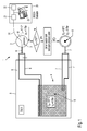
- a system 1 for monitoring a composite component 10 during its production or fabrication according to a particular preferred embodiment of the invention is illustrated schematically.
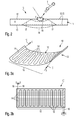
- An example of the composite component 10 according to the present invention is shown schematically, but with some detail, in Fig. 2 and Fig. 3a of the drawings, and will be discussed further below.
- the composite component 10 is provided as a structural member for an aircraft and is formed in a sandwich construction as a panel component with a core 11 of foam material and upper and lower layers 12, 13 of a fibre-reinforced polymer. Further, reinforcing elements (not shown) that are themselves formed from fibre-reinforced composites (e.g. prepregs) may be integrated in the core 11 of the component 10.
- the panel component 10 will typically have a thickness in the range of 1 to 10 mm, and more preferably in the range of 2 to 5 mm. It should be noted that, while the system 1 of the invention can also be employed in the production of a component constructed merely in one phase and comprising only curable plastic material, its use in the fabrication of a fibre-reinforced composite is particularly preferred.
- the system 1 includes a storage tank 2 in which a liquid matrix material M is held.
- the storage tank 2 may be filled with a curable resin such as, for example, an epoxy resin or an epoxy-amine resin.
- the matrix material M in the storage tank 2 is in the liquid state.
- a first heating device 3 the storage tank 2 or the matrix material M in the tank 2 can be heated to a desired temperature.
- the tank 2 is desirably heated via the first heating device 3 to a temperature of about 80°C.
- the system 1 includes a moulding tool 4 having a region for receiving the core 11 of the composite component 10 and a filling region 5 in which reinforcing fibres (not shown) are arranged, e.g. in the form of a fibre array (e.g. provided as a non-woven matting or in an arbitrary array) or in the form of one or more layers of a fibre fabric, on the upper and lower sides of the core 11.
- the reinforcing fibres are carbon fibres and the core 11 may, for example, comprise a closed-cell polymethacrylimide foam.
- the filling region 5 formed in the moulding tool 4 includes two sections which extend in a substantially planar manner along two opposing sides of the core 11.
- the upper and lower layers 12, 13 of the component 10 covering the core 11 of the panel component 10 can be generated from a fibre-reinforced composite material; e.g. as a carbon-fibre-reinforced plastic material.
- the system 1 and method of the invention involve the arrangement of at least one optical fibre 14 over a monitoring area 15 of the panel 10.
- the monitoring area 15 essentially corresponds to an outer surface of the panel 10.
- the optical fibre 14 traces a continuous serpentine or meandering path over the monitoring area 15 and end regions 16 of the optical fibre 14 extend from a periphery of the panel component 10 for the input and output of an optical signal S, to be described shortly.
- Fig. 3a of the drawings shows a single optical fibre 14 on the upper side 12 of the panel component 10, it will be appreciated that another optical fibre 14 in a corresponding configuration may also be present on the lower side 13 of the panel.
- each of the upper and lower sides 12, 13 of the panel 10 may include more than one optical fibre 14 tracing a continuous path over the monitoring area 15, as shown in the alternative embodiment of Fig. 3b .
- two optical fibres 14 extend in serpentine paths generally perpendicular to each other over the monitoring area 15.
- Such an arrangement of double optical fibres 14 is desirably provided on each of the upper and lower sides 12, 13 of the panel 10. This configuration provides the system 1 of the invention with a greater sensor density over the monitoring area 15, which in turn provides a higher degree of resolution or accuracy in the detections or measurements made with the system 1, as described below.
- each optical fibre 14 is arranged in the desired configuration in the filling region 5 of the moulding tool 4 together with the reinforcing fibres.
- the optical fibre(s) 14 may be fixed or attached to the reinforcing fibres to ensure they remain in the desired path over the intended monitoring area 15 as the filling region 5 is filled with liquid matrix material M from the tank 2 and the composite component 10 is cast in the moulding tool 4.
- the filling region 5 of the moulding tool 4 is connected to the storage tank 2 via one or more matrix material supply lines 6. Further, the filling region 5 of the moulding tool 4 is also connected via a line 7 to a conveying device 8 which is designed in the form of a vacuum pump. In the embodiment of the system 1 shown in Fig. 1 , the conveying device 8 serves to generate an under-pressure in the filling region 5 of moulding tool 4, thereby to convey matrix material M out of the storage tank 2 into the filling region 5 of the moulding tool 4. With this configuration, the tank 2 is not subjected to elevated pressure.
- the matrix material M may be conveyed out of the storage tank 2 into the material supply line 6 and into the filling region 5 of the moulding tool 4.
- the system 1 includes a second heating device 9 in the form of an oven surrounding the moulding tool 4, which serves to heat the moulding tool 4 to a desired operating temperature.
- the moulding tool 4 may be heated to a temperature of about 120°C for the supply of the matrix material M from the storage tank 2 into the filling region 5.
- the second heating device 9 may also be utilised to heat the moulding tool 4 to a curing temperature to effect curing of the matrix material. For example, a curing temperature of about 180°C is possible.
- the optical fibre(s) 14 incorporated in the filling region 5 of the moulding tool 4 is/are arranged to extend from the moulding tool through the resin supply line 6 for connection to an optical signal generating device 21 in the form of a laser. That is, the signal generating device 21 is connected in communication with the optical fibre(s) 14 in the resin supply line 6 and the filling region 5 of the moulding tool 4 and is configured to generate and transmit an optical signal S in the form of laser light pulses along each optical fibre 14. Further, the system 1 includes a detector device 22 configured to detect backscattering, particularly Brillouin scattering, from the optical signals S transmitted along the optical fibre(s) 14.
- the detector device 22 includes an evaluating unit 23 having a computer processor and/or a spectrometer for performing a Brillouin Optical Correlation Domain Analysis (BOCDA) evaluation of the backscattering detected.
- BOCDA Brillouin Optical Correlation Domain Analysis
- the detector device 22 can detect the wavelength of the backscattered light and can ascertain from the backscattered wavelengths any significant change of temperature in the environment along the length of the optical fibre(s) 14.
- the conveying device or vacuum pump 8 of system 1 When a temperature To of the moulding tool 4 in the oven 9 is at 120°C, the conveying device or vacuum pump 8 of system 1 generates a vacuum or under-pressure P 0 of about 0 bar in the filling region 5 of the moulding tool 4 such that the matrix material M in the tank 2 at a temperature T 1 of about 80°C and pressure P 1 of about 1 bar is drawn out of the tank 2 and drawn along the supply line 6 into the filling region 5 of the moulding tool, so that the reinforcing fibres arranged in the filling region 5 are impregnated with matrix material.
- the movement of a flow front of the material M through the supply lines 6 and the filling region 5, can then be monitored via the detector device 22.
- the optical fibres 14 cooperate with the laser signal generator 21 and the detector device 22 to enable a virtually continuous monitoring of the progress of the flow front of the material M in the supply line 6 and through the filling region 5 in the monitoring area of the component 10 as it is formed in moulding tool 4.
- the movement of a flow front of the matrix material M out of the storage tank 2 with a temperature T 1 of 80°C through the supply lines 6 and into the filling region 5 of the heated moulding tool 4 can thus be detected and traced by the BOCDA detector device 22 of the inventive system 1.
- the relatively cooler flow front of the resin is registered by the position along the optical fibres 14 of a corresponding temperature drop or decreasing temperature gradient in the BOCDA detector device.
- the optical fibres 14 have a small physical volume, the flow of matrix material M through the supply line 6 and through the filling region 5 of the moulding tool 4 is not significantly affected, even when the optical fibre 14 are directly integrated into the filling region 6 of the moulding tool 4.
- the parameters evaluated by the evaluating unit 23 may be supplied to an electrical control unit.
- the control unit may control operation of the first heating device 3 for heating the matrix material M in the tank 2, and/or operation of the second heating device 9 for heating the moulding tool, as well as operation of the conveying device 8 for conveying the material M out of the storage tank 2 into the filling region 5 of the moulding tool 4.
- the control unit is able to influence movement of the flow front of the matrix material M through the material supply line 6 and the filling region 5 of the moulding tool 4 in dependence upon signals output by the detector device 22 and the evaluating unit 23.
- the control unit may, for example, compare the rate of movement of the flow front of the matrix material M with predetermined values saved in a memory of the control unit.
- the system 1 As the system 1 operates with high-resolution and effectively continuously, the system 1 is able to monitor the advancing flow front and the already saturated part of the filling region very precisely while also determining its temperature distribution very accurately.
- the scattering of the optical signals may then vary where the fibres contact the liquid matrix material regardless of any temperature differential, such that the flow front of the resin can be monitored even without a temperature difference in the production system.
- the various advantages of this system 1 of the invention include: (a) the optical fibres are thin and light-weight, such that their presence has negligible effect on the structural mass or performance.
- the BOCDA distributed optical fibre sensors are electromagnetically (EM) tolerable and corrosion resistant;
- the temperature front actually advances ahead of the resin flow front, such that a real-time measurement of the flow front is possible;
- the almost complete temperature detection of the fabrication component can be used to regulate the oven temperature under consideration of the reaction kinetics;
- the optical fibres can be recovered after production of the composite component and re-used, i.e.
- the optical fibres can alternatively be arranged embedded in the matrix material of the composite component and used later for "structural health monitoring" of the component in service; and (g) in contrast to the fibre Bragg grating (FBG), no gratings are required in the optical fibre so that conventional optical glass fibres may be used and measurements are theoretically possible over the entire length of the optical fibres, whereby a continuous monitoring of the flow front can be achieved.
- FBG fibre Bragg grating
- those fibres 14 can also be used to monitor the structural integrity of the component 10 in service over the course of its service-life.
- structural damage can occur during the service-life of the composite component 10 which is not necessarily able to be detected by a visual inspection.
- differences in the temperature of the resin layers 12, 13 and the foam core 11 in service can lead to cracking (e.g. conical shear cracks 17) in the foam core 11 and, thus, to loss of structural integrity.
- an unintended impact X to the panel component 10 for example by accidentally dropping a solid item, such as a tool T, as illustrated in Fig. 2 , can cause undesired bending 18 in the CFRP outer layers 12, 13 of the component and may potentially lead to surface delamination 19.
- the present invention thus offers convenient temperature and strain monitoring via the embedded optical glass fibres 14 of the BOCDA system 1.
- a BOCDA control unit 20 with a laser signal generating device 21 and a detector device 22 is incorporated in the aircraft.
- the detection and evaluation of variations in the wavelengths back-scattered to the detector device 22 from light signals transmitted by the laser source 21 over the monitoring area 15 enable conclusions regarding deformations in the optical fibres 14 in the longitudinal direction caused by a mechanical strain in the component 10.
- a complete cessation of signal transmission, on the other hand, would suggest a break in an optical fibre 14 and thus more substantial damage to the component 10.
- the optical fibres 14 of the component 10 are connected via their end regions 16 to operating units of the aircraft and the signals generated and transmitted by the signal generating device 21 are control signals for the operating units.
- the optical fibres 14 are used for transmission of optical control signals to the operating units (not shown) of the aircraft in service, while the BOCDA distributed sensors at the same time detect back-scattering from the control signals to monitor the structural integrity of the panels 10.
- the composite panel components 10 may form sections of a hull or fuselage structure 28 of the aircraft.
- a fuselage structure 28 typically has three or four sections 29, e.g. formed as an upper crown shell section 29', a base shell section 29" and side shell sections 29"'.
- control signals By transmitting control signals in parallel to the operating units of the aircraft via panel components 10 in each of the sections 29', 29", 29'", the control signals can be sent to the operating units with sufficient redundancy and all of the fuselage sections 29', 29", 29'" can be structurally monitored simultaneously.
- the first box I represents the step of providing a composite component comprising reinforcing fibres arranged in at least one layer and/or in an array which are encompassed by a matrix material, as described above.
- this first step of providing the composite component involves fabricating the component using a moulding tool.
- the second box II represents the step of arranging at least one optical fibre to extend in a continuous path over a monitoring area of the composite component in contact with the matrix material.
- this second step is performed during fabrication or production of the composite component and includes arranging the optical fibre in a filling region of a moulding tool to be filled with the matrix material in a liquid form.
- the next box III represents a step of generating and transmitting an optical signal along the optical fibre.
- the optical signals may include control signals transmitted to operational units of the air- or spacecraft along the optical fibre.
- the fourth box IV represents the step of detecting scattering, in particular backscattering, of the optical signal transmitted along the optical fibre.
- this fourth step involves detecting a parameter that is characteristic of flow of the matrix material through the filling region of the moulding tool during production of the composite component.
- the fourth step rather involves detecting a parameter characteristic of the structural integrity of the component.
- FIG. 6 an aircraft 30 is shown schematically in Fig. 6 with a fuselage structure 28 that incorporates one or more of the composite panel components 10 of the invention as described in detail above with reference to Figs. 2 and 3 .
- the terms “with”, “comprise”, “comprising”, “include”, “including”, “contain”, “containing”, “have”, “having”, and any variations thereof, are intended to be understood in an inclusive (i.e. non-exclusive) sense, such that the process, method, device, apparatus or system described herein is not limited to those features or parts or elements or steps recited but may include other elements, features, parts or steps not expressly listed or inherent to such process, method, article, or apparatus.
- the terms “a” and “an” used herein are intended to be understood as meaning one or more unless explicitly stated otherwise.
- the terms “first”, “second”, “third”, etc. are used merely as labels, and are not intended to impose numerical or chronological requirements on, or to establish a ranking of importance of, their objects.
Landscapes
- Physics & Mathematics (AREA)
- General Physics & Mathematics (AREA)
- Engineering & Computer Science (AREA)
- Chemical & Material Sciences (AREA)
- Electromagnetism (AREA)
- Aviation & Aerospace Engineering (AREA)
- Composite Materials (AREA)
- Mechanical Engineering (AREA)
- Analytical Chemistry (AREA)
- Moulding By Coating Moulds (AREA)
- Measuring Temperature Or Quantity Of Heat (AREA)
Claims (15)
- Système (1) de surveillance d'un composant en production et / ou en service, comprenant :- un composant (10) comprenant des fibres de renforcement qui sont englobées par un matériau de matrice (M) ;- au moins une fibre optique (14) disposée pour s'étendre suivant un trajet continu au-dessus d'une zone de surveillance (15) de l'élément composite en contact avec le matériau de matrice ;- un générateur de signal (21) configuré pour émettre un signal optique le long de la au moins une fibre optique (14) ; et- un dispositif de détection (22) configuré pour détecter la diffusion, et en particulier la rétrodiffusion, du signal optique transmis le long de la au moins une fibre optique ;dans lequel la au moins une fibre (14) est disposée dans une région de remplissage (5) d'un outil de moulage (4) à remplir avec le matériau de matrice (M) sous une forme liquide pendant la production de l'élément composite (10), et
dans lequel le dispositif de détection (22) est configuré pour détecter un paramètre et une caractéristique d'écoulement du matériau de matrice (M) à travers la région de remplissage (5) pendant la production de l'élément composite (10). - Système (1) selon la revendication 1, dans lequel le dispositif de détection est configuré pour détecter une ou plusieurs de la diffusion de Rayleigh, de diffusion de Raman et de la diffusion de Brillouin du signal optique transmis le long de la fibre optique, et dans lequel le système est configuré pour évaluer la dispersion détectée par le dispositif de détection.
- Système (1) selon la revendication 1 ou la revendication 2, dans lequel la au moins une fibre optique (14) est agencée de manière à s'étendre dans un trajet en serpentin ou en méandres sur la zone de surveillance (15), adjacente à une surface externe de l'élément composite (10) ou englobée dans le matériau de matrice (M) du composant composite, et dans lequel la au moins une fibre optique est connectée pour une communication optique avec le générateur de signal (21).
- Système (1) selon l'une quelconque des revendications 1 à 3, dans lequel la zone de surveillance (15) au cours de laquelle la au moins une fibre optique (14) s'étend correspond à et / ou est sensiblement parallèle à une surface externe (12, 13) de l'élément composite (10), ou correspond à, et / ou est sensiblement parallèle à une épaisseur de l'élément composite (10).
- Système (1) selon l'une quelconque des revendications 1 à 4, comportant en outre une unité de commande qui est adaptée pour commander l'écoulement du matériau de matrice (M) dans et / ou à travers la région de remplissage (5) de l'outil moulage en fonction du paramètre détecté par le dispositif de détection (22).
- Système (1) selon l'une quelconque des revendications 1 à 5, dans lequel la au moins une fibre optique (14) disposée dans la zone de remplissage (5) de l'outil de moulage est séparée du composant (10) par l'intermédiaire d'un dispositif de séparation ou est disposée pour être englobée par le matériau de matrice (M) dans l'élément composite.
- Système (1) selon l'une quelconque des revendications 1 à 6, dans lequel l'élément composite (10) est monolithique ou présente une structure en sandwich avec un noyau qui est reçu dans l'outil de moulage, la région de remplissage de l'outil de moulage s'étendant le long d'une surface du noyau.
- Système (1) selon l'une quelconque des revendications 1 à 7, dans lequel l'élément composite (10) est incorporé dans la structure d'un aéronef ou d'un engin spatial, spécifiquement sous la forme d'un élément de structure, et dans lequel le générateur de signal (21) est en outre configuré pour transmettre des signaux de commande optique à une ou plusieurs unités opérationnelles de l'aéronef ou de l'engin spatial le long de la fibre optique (14).
- Système (1) selon la revendication 8, dans lequel le dispositif de détection (22) est en outre configuré pour détecter une caractéristique de paramètres d'intégrité de structure de l'élément composite.
- Procédé de surveillance d'un composant à fibres renforcées en production, comprenant les étapes consistant à :- fournir un élément composite (10) ayant des fibres de renforcement qui sont englobées par un matériau de matrice (M) ;- agencer au moins une fibre optique (14) pour s'étendre dans un trajet continu au-dessus d'une zone de surveillance (15) de l'élément composite pour un contact avec le matériau de matrice,- transmettre un signal optique le long de la au moins une fibre optique ; et- détecter une diffusion, en particulier une rétrodiffusion, du signal optique transmis le long de la au moins une fibre optique ;dans lequel l'étape d'agencement comporte d'agencer la au moins une fibre optique dans une région de remplissage (5) d'un outil de moulage (4) à remplir avec le matériau de matrice sous une forme liquide pendant la production de l'élément composite ; et
dans lequel l'étape de détection comprend de détecter un paramètre qui est caractéristique de l'écoulement du matériau de matrice à travers la région de remplissage pendant la production de l'élément composite. - Procédé selon la revendication 10, dans lequel l'étape de détection d'une rétrodiffusion du signal optique comporte de détecter l'une quelconque ou plusieurs de la diffusion de Rayleigh, de la diffusion de Raman et de la diffusion de Brillouin du signal optique transmis le long de la fibre optique, et dans lequel le procédé comporte en outre l'étape consistant à :- analyser ou évaluer la diffusion détectée.
- Procédé selon la revendication 10 ou la revendication 11, dans lequel l'étape d'agencement comporte d'agencer la au moins une fibre optique pour s'étendre dans un trajet en serpentin ou en méandres sur la zone de surveillance, de manière préférée adjacente à une surface externe de l'élément composite et/ou englobée dans le matériau de matrice, et
dans lequel le procédé comporte en outre l'étape consistant à relier la au moins une fibre optique en vue d'une communication avec un dispositif de génération de signal (21). - Procédé selon l'une quelconque des revendications 10 à 12, dans lequel le procédé comporte en outre l'étape consistant à :- commander l'écoulement du matériau de matrice dans et / ou à travers la région de remplissage de l'outil de moulage en fonction du paramètre détecté.
- Procédé selon l'une quelconque des revendications 10 à 12, dans lequel :l'élément composite est incorporé dans une structure de coque d'un aéronef ou d'un engin spatial, spécifiquement sous la forme d'un élément de structure ;l'étape de transmission de signaux comporte de transmettre des signaux de commande optique à une ou plusieurs unités opérationnelles de l'aéronef ou de l'engin spatial le long de la au moins une fibre optique ; etl'étape de détection comporte de détecter un paramètre qui est caractéristique de l'intégrité structurelle de l'élément composite.
- Aéronef ou engin spatial comportant un système de surveillance d'un composant en service selon la revendication 8 ou la revendication 9.
Priority Applications (3)
| Application Number | Priority Date | Filing Date | Title |
|---|---|---|---|
| EP14191848.2A EP2851669A1 (fr) | 2012-06-05 | 2012-06-05 | Système et procédé de surveillance d'un composant d'avion ou de vaisseau spatial en cours de production et/ou de service |
| EP12170869.7A EP2672234B1 (fr) | 2012-06-05 | 2012-06-05 | Système et procédé de surveillance d'un composant lors de sa production ainsi que pendant son fonctionnement |
| US13/909,667 US9533453B2 (en) | 2012-06-05 | 2013-06-04 | System for monitoring flow of a matrix material in a molding tool using a scattering optical signal transmitted along at least one optical fiber during production of a component |
Applications Claiming Priority (1)
| Application Number | Priority Date | Filing Date | Title |
|---|---|---|---|
| EP12170869.7A EP2672234B1 (fr) | 2012-06-05 | 2012-06-05 | Système et procédé de surveillance d'un composant lors de sa production ainsi que pendant son fonctionnement |
Related Child Applications (1)
| Application Number | Title | Priority Date | Filing Date |
|---|---|---|---|
| EP14191848.2A Division EP2851669A1 (fr) | 2012-06-05 | 2012-06-05 | Système et procédé de surveillance d'un composant d'avion ou de vaisseau spatial en cours de production et/ou de service |
Publications (2)
| Publication Number | Publication Date |
|---|---|
| EP2672234A1 EP2672234A1 (fr) | 2013-12-11 |
| EP2672234B1 true EP2672234B1 (fr) | 2014-12-03 |
Family
ID=46548192
Family Applications (2)
| Application Number | Title | Priority Date | Filing Date |
|---|---|---|---|
| EP14191848.2A Withdrawn EP2851669A1 (fr) | 2012-06-05 | 2012-06-05 | Système et procédé de surveillance d'un composant d'avion ou de vaisseau spatial en cours de production et/ou de service |
| EP12170869.7A Active EP2672234B1 (fr) | 2012-06-05 | 2012-06-05 | Système et procédé de surveillance d'un composant lors de sa production ainsi que pendant son fonctionnement |
Family Applications Before (1)
| Application Number | Title | Priority Date | Filing Date |
|---|---|---|---|
| EP14191848.2A Withdrawn EP2851669A1 (fr) | 2012-06-05 | 2012-06-05 | Système et procédé de surveillance d'un composant d'avion ou de vaisseau spatial en cours de production et/ou de service |
Country Status (2)
| Country | Link |
|---|---|
| US (1) | US9533453B2 (fr) |
| EP (2) | EP2851669A1 (fr) |
Cited By (1)
| Publication number | Priority date | Publication date | Assignee | Title |
|---|---|---|---|---|
| US12092515B2 (en) | 2021-04-16 | 2024-09-17 | Viavi Solutions Inc. | Optical fiber-based sensing membrane layout |
Families Citing this family (23)
| Publication number | Priority date | Publication date | Assignee | Title |
|---|---|---|---|---|
| EP2590803B1 (fr) * | 2010-07-08 | 2017-03-15 | Vestas Wind Systems A/S | Système de mesure de température d'aubes de turbine et procédé de fabrication d'aubes de turbine |
| GB201401921D0 (en) * | 2014-02-05 | 2014-03-19 | Cementation Skanska Ltd | Method of monitoring subsurface concrete structures |
| GB2529674B (en) * | 2014-08-28 | 2019-07-10 | Silixa Ltd | Flexible Substrate Fiber Optic Sensing Mat For Distributed Acoustic Sensing |
| US9874519B2 (en) * | 2014-11-03 | 2018-01-23 | Ofs Fitel, Llc | Distributed Brillouin sensor |
| JP6640583B2 (ja) * | 2016-02-02 | 2020-02-05 | 三菱重工業株式会社 | 複合材の成形装置及び複合材の成形方法 |
| JP6754585B2 (ja) * | 2016-02-17 | 2020-09-16 | 帝人株式会社 | モニタリング装置及びモニタリング方法 |
| DE102016205099A1 (de) * | 2016-03-29 | 2017-10-05 | 3D Schilling Gmbh | Vorrichtung und Verfahren zur Überwachung mechanischer und/oder thermischer Parameter in Spritzgussteilen |
| CA2968097C (fr) * | 2016-05-19 | 2024-01-09 | Kidde Technologies, Inc. | Detection de surchauffe d'un aeronef au moyen de la technologie a fibre optique destinee a la surveillance d'etat du systeme |
| EP3258221B1 (fr) * | 2016-06-13 | 2021-07-28 | Airbus Defence and Space GmbH | Système de détection |
| US11673352B2 (en) * | 2016-09-20 | 2023-06-13 | United States Of America As Represented By The Administrator Of Nasa | Automated wave guide system for in-process monitoring of carbon fiber reinforced polymer (CFRP) composite laminates with hanning window tone-bursts of center frequencies from 100-225 kHz and 100-350 kHz |
| DE102017221821A1 (de) * | 2017-12-04 | 2019-06-06 | Airbus Defence and Space GmbH | Messanordnung zum Messen von Prozess- und Strukturparametern eines Faserverbundmaterials entlang einer Messstrecke |
| JP6873073B2 (ja) | 2018-03-08 | 2021-05-19 | 三菱重工業株式会社 | 評価方法及び評価システム |
| EP3561473A1 (fr) * | 2018-04-25 | 2019-10-30 | Airbus Operations, S.L. | Structure composite avec fonction de localisation de dommages et procédé de fabrication d'une structure composite avec fonction de localisation de dommages |
| US11590676B2 (en) * | 2018-08-21 | 2023-02-28 | United States Of America As Represented By The Administrator Of Nasa | Guided wave-based system for cure monitoring of composites using piezoelectric discs and fiber Bragg gratings/phase-shifted Bragg gratings |
| US11239919B2 (en) * | 2018-12-20 | 2022-02-01 | Acacia Communications, Inc. | Side channel communication for an optical coherent transceiver |
| EP3750637A1 (fr) * | 2019-03-29 | 2020-12-16 | Airbus Operations GmbH | Dispositif pour transfert de laque |
| EP3725539A1 (fr) | 2019-03-29 | 2020-10-21 | Airbus Operations GmbH | Dispositif de transfert de vernis |
| EP3722007A1 (fr) | 2019-03-29 | 2020-10-14 | Airbus Operations GmbH | Dispositif de transfert de vernis |
| EP3722009A1 (fr) | 2019-03-29 | 2020-10-14 | Airbus Operations GmbH | Dispositif et système |
| EP3733300A1 (fr) | 2019-04-11 | 2020-11-04 | Airbus Operations GmbH | Dispositif pour transfert de laque |
| EP3725422A1 (fr) | 2019-04-12 | 2020-10-21 | Airbus Operations GmbH | Dispositif de transfert de vernis |
| EP3760418B1 (fr) * | 2019-07-03 | 2022-06-01 | Airbus Operations, S.L.U. | Système de surveillance d'écoulement de résine |
| DE102021124635B3 (de) | 2021-09-23 | 2022-12-08 | Deutsches Zentrum für Luft- und Raumfahrt e.V. | Raumobjekt-Aufprallsensor, Raumobjekt-Aufpralleinrichtung, Raumflugobjekt und Raumobjekt-Solarpanel |
Family Cites Families (10)
| Publication number | Priority date | Publication date | Assignee | Title |
|---|---|---|---|---|
| US4812645A (en) * | 1981-08-24 | 1989-03-14 | G2 Systems Corporation | Structural monitoring system using fiber optics |
| US4947693A (en) * | 1987-07-28 | 1990-08-14 | Grumman Aerospace Corporation | Discrete strain sensor |
| US4936649A (en) * | 1989-01-25 | 1990-06-26 | Lymer John D | Damage evaluation system and method using optical fibers |
| US6004639A (en) * | 1997-10-10 | 1999-12-21 | Fiberspar Spoolable Products, Inc. | Composite spoolable tube with sensor |
| CN1319715C (zh) * | 2001-08-07 | 2007-06-06 | 东丽株式会社 | 大型frp构件的制造方法 |
| JP2004101472A (ja) * | 2002-09-12 | 2004-04-02 | Mitsubishi Heavy Ind Ltd | 光ファイバを用いた歪み温度計測装置 |
| DE102007042546B4 (de) * | 2007-09-07 | 2010-01-14 | Ulrich Glombitza | Verfahren zur ortsaufgelösten Temperaturmessung in einem Rohr- oder Kanalsystem |
| DE102007062111A1 (de) | 2007-12-21 | 2009-07-02 | Airbus Deutschland Gmbh | Abschirmanordnung für insbesondere elektrische Leitungen in Flugzeugen |
| DE102010001197B4 (de) * | 2010-01-25 | 2019-05-29 | Draka Cable Wuppertal Gmbh | Sensorelement und Verfahren zu seiner Herstellung und Verwendung |
| DE102010035958B8 (de) * | 2010-08-31 | 2012-07-05 | Airbus Operations Gmbh | Vorrichtung und Verfahren zur Herstellung eines Bauteils sowie Flugzeugstrukturbauteil |
-
2012
- 2012-06-05 EP EP14191848.2A patent/EP2851669A1/fr not_active Withdrawn
- 2012-06-05 EP EP12170869.7A patent/EP2672234B1/fr active Active
-
2013
- 2013-06-04 US US13/909,667 patent/US9533453B2/en active Active
Cited By (1)
| Publication number | Priority date | Publication date | Assignee | Title |
|---|---|---|---|---|
| US12092515B2 (en) | 2021-04-16 | 2024-09-17 | Viavi Solutions Inc. | Optical fiber-based sensing membrane layout |
Also Published As
| Publication number | Publication date |
|---|---|
| US9533453B2 (en) | 2017-01-03 |
| EP2672234A1 (fr) | 2013-12-11 |
| US20130341497A1 (en) | 2013-12-26 |
| EP2851669A1 (fr) | 2015-03-25 |
Similar Documents
| Publication | Publication Date | Title |
|---|---|---|
| EP2672234B1 (fr) | Système et procédé de surveillance d'un composant lors de sa production ainsi que pendant son fonctionnement | |
| Rocha et al. | Sensors for process and structural health monitoring of aerospace composites: A review | |
| Giurgiutiu | Structural health monitoring (SHM) of aerospace composites | |
| Matveenko et al. | Measurement of strains by optical fiber Bragg grating sensors embedded into polymer composite material | |
| Kefal et al. | An experimental implementation of inverse finite element method for real-time shape and strain sensing of composite and sandwich structures | |
| Rajan et al. | Structural health monitoring of composite structures using fiber optic methods | |
| Rufai et al. | Cure monitoring and structural health monitoring of composites using micro-braided distributed optical fibre | |
| Qing et al. | Advances in the development of built-in diagnostic system for filament wound composite structures | |
| Gupta et al. | Fiber optic sensors for monitoring flow in vacuum enhanced resin infusion technology (VERITy) process | |
| JP6148253B2 (ja) | 多成分シート材料の製造プロセスのオンライン制御方法 | |
| Ghoshal et al. | Experimental investigations in embedded sensing of composite components in aerospace vehicles | |
| Torres | Parameters’ monitoring and in-situ instrumentation for resin transfer moulding: A review | |
| Herszberg et al. | Damage assessment and monitoring of composite ship joints | |
| CN102380958B (zh) | 用于制造部件的设备和方法以及飞机结构部件 | |
| Yoo et al. | Simulation of curing process of carbon/epoxy composite during autoclave degassing molding by considering phase changes of epoxy resin | |
| JP6203142B2 (ja) | ハニカムサンドイッチ構造体およびその製造方法 | |
| Sala et al. | Fibre optics health monitoring for aeronautical applications | |
| Jeong et al. | In-situ resin flow monitoring in VaRTM process by using optical frequency domain reflectometry and long-gauge FBG sensors | |
| Riccio et al. | Positioning of embedded optical fibres sensors for the monitoring of buckling in stiffened composite panels | |
| Ryu et al. | Buckling behavior monitoring of a composite wing box using multiplexed and multi-channeled built-in fiber Bragg grating strain sensors | |
| Yu et al. | In-situ cure monitoring of thick CFRP using multifunctional piezoelectric-fiber hybrid sensor network | |
| Keulen et al. | Embedded fiber optic sensors for monitoring processing, quality and structural health of resin transfer molded components | |
| Christian et al. | Real-time quantification of damage in structural materials during mechanical testing | |
| Kosters et al. | Structural health monitoring and impact detection for primary aircraft structures | |
| Takeda | Fiber optic sensor-based SHM technologies for aerospace applications in Japan |
Legal Events
| Date | Code | Title | Description |
|---|---|---|---|
| PUAI | Public reference made under article 153(3) epc to a published international application that has entered the european phase |
Free format text: ORIGINAL CODE: 0009012 |
|
| AK | Designated contracting states |
Kind code of ref document: A1 Designated state(s): AL AT BE BG CH CY CZ DE DK EE ES FI FR GB GR HR HU IE IS IT LI LT LU LV MC MK MT NL NO PL PT RO RS SE SI SK SM TR |
|
| AX | Request for extension of the european patent |
Extension state: BA ME |
|
| 17P | Request for examination filed |
Effective date: 20140331 |
|
| RBV | Designated contracting states (corrected) |
Designated state(s): AL AT BE BG CH CY CZ DE DK EE ES FI FR GB GR HR HU IE IS IT LI LT LU LV MC MK MT NL NO PL PT RO RS SE SI SK SM TR |
|
| RIC1 | Information provided on ipc code assigned before grant |
Ipc: G01M 5/00 20060101ALI20140513BHEP Ipc: G01M 11/08 20060101ALI20140513BHEP Ipc: G01L 1/24 20060101ALI20140513BHEP Ipc: G01D 5/353 20060101AFI20140513BHEP Ipc: G01K 11/32 20060101ALN20140513BHEP |
|
| GRAP | Despatch of communication of intention to grant a patent |
Free format text: ORIGINAL CODE: EPIDOSNIGR1 |
|
| INTG | Intention to grant announced |
Effective date: 20140708 |
|
| GRAS | Grant fee paid |
Free format text: ORIGINAL CODE: EPIDOSNIGR3 |
|
| GRAA | (expected) grant |
Free format text: ORIGINAL CODE: 0009210 |
|
| AK | Designated contracting states |
Kind code of ref document: B1 Designated state(s): AL AT BE BG CH CY CZ DE DK EE ES FI FR GB GR HR HU IE IS IT LI LT LU LV MC MK MT NL NO PL PT RO RS SE SI SK SM TR |
|
| REG | Reference to a national code |
Ref country code: GB Ref legal event code: FG4D |
|
| REG | Reference to a national code |
Ref country code: AT Ref legal event code: REF Ref document number: 699627 Country of ref document: AT Kind code of ref document: T Effective date: 20141215 Ref country code: CH Ref legal event code: EP |
|
| REG | Reference to a national code |
Ref country code: IE Ref legal event code: FG4D |
|
| REG | Reference to a national code |
Ref country code: DE Ref legal event code: R096 Ref document number: 602012004060 Country of ref document: DE Effective date: 20150115 |
|
| REG | Reference to a national code |
Ref country code: NL Ref legal event code: VDEP Effective date: 20141203 |
|
| REG | Reference to a national code |
Ref country code: AT Ref legal event code: MK05 Ref document number: 699627 Country of ref document: AT Kind code of ref document: T Effective date: 20141203 |
|
| PG25 | Lapsed in a contracting state [announced via postgrant information from national office to epo] |
Ref country code: LT Free format text: LAPSE BECAUSE OF FAILURE TO SUBMIT A TRANSLATION OF THE DESCRIPTION OR TO PAY THE FEE WITHIN THE PRESCRIBED TIME-LIMIT Effective date: 20141203 Ref country code: FI Free format text: LAPSE BECAUSE OF FAILURE TO SUBMIT A TRANSLATION OF THE DESCRIPTION OR TO PAY THE FEE WITHIN THE PRESCRIBED TIME-LIMIT Effective date: 20141203 Ref country code: ES Free format text: LAPSE BECAUSE OF FAILURE TO SUBMIT A TRANSLATION OF THE DESCRIPTION OR TO PAY THE FEE WITHIN THE PRESCRIBED TIME-LIMIT Effective date: 20141203 Ref country code: NL Free format text: LAPSE BECAUSE OF FAILURE TO SUBMIT A TRANSLATION OF THE DESCRIPTION OR TO PAY THE FEE WITHIN THE PRESCRIBED TIME-LIMIT Effective date: 20141203 Ref country code: NO Free format text: LAPSE BECAUSE OF FAILURE TO SUBMIT A TRANSLATION OF THE DESCRIPTION OR TO PAY THE FEE WITHIN THE PRESCRIBED TIME-LIMIT Effective date: 20150303 |
|
| REG | Reference to a national code |
Ref country code: LT Ref legal event code: MG4D |
|
| PG25 | Lapsed in a contracting state [announced via postgrant information from national office to epo] |
Ref country code: HR Free format text: LAPSE BECAUSE OF FAILURE TO SUBMIT A TRANSLATION OF THE DESCRIPTION OR TO PAY THE FEE WITHIN THE PRESCRIBED TIME-LIMIT Effective date: 20141203 Ref country code: GR Free format text: LAPSE BECAUSE OF FAILURE TO SUBMIT A TRANSLATION OF THE DESCRIPTION OR TO PAY THE FEE WITHIN THE PRESCRIBED TIME-LIMIT Effective date: 20150304 Ref country code: LV Free format text: LAPSE BECAUSE OF FAILURE TO SUBMIT A TRANSLATION OF THE DESCRIPTION OR TO PAY THE FEE WITHIN THE PRESCRIBED TIME-LIMIT Effective date: 20141203 Ref country code: RS Free format text: LAPSE BECAUSE OF FAILURE TO SUBMIT A TRANSLATION OF THE DESCRIPTION OR TO PAY THE FEE WITHIN THE PRESCRIBED TIME-LIMIT Effective date: 20141203 Ref country code: SE Free format text: LAPSE BECAUSE OF FAILURE TO SUBMIT A TRANSLATION OF THE DESCRIPTION OR TO PAY THE FEE WITHIN THE PRESCRIBED TIME-LIMIT Effective date: 20141203 Ref country code: AT Free format text: LAPSE BECAUSE OF FAILURE TO SUBMIT A TRANSLATION OF THE DESCRIPTION OR TO PAY THE FEE WITHIN THE PRESCRIBED TIME-LIMIT Effective date: 20141203 Ref country code: CY Free format text: LAPSE BECAUSE OF FAILURE TO SUBMIT A TRANSLATION OF THE DESCRIPTION OR TO PAY THE FEE WITHIN THE PRESCRIBED TIME-LIMIT Effective date: 20141203 |
|
| REG | Reference to a national code |
Ref country code: FR Ref legal event code: PLFP Year of fee payment: 4 |
|
| PG25 | Lapsed in a contracting state [announced via postgrant information from national office to epo] |
Ref country code: RO Free format text: LAPSE BECAUSE OF FAILURE TO SUBMIT A TRANSLATION OF THE DESCRIPTION OR TO PAY THE FEE WITHIN THE PRESCRIBED TIME-LIMIT Effective date: 20141203 Ref country code: SK Free format text: LAPSE BECAUSE OF FAILURE TO SUBMIT A TRANSLATION OF THE DESCRIPTION OR TO PAY THE FEE WITHIN THE PRESCRIBED TIME-LIMIT Effective date: 20141203 Ref country code: CZ Free format text: LAPSE BECAUSE OF FAILURE TO SUBMIT A TRANSLATION OF THE DESCRIPTION OR TO PAY THE FEE WITHIN THE PRESCRIBED TIME-LIMIT Effective date: 20141203 Ref country code: EE Free format text: LAPSE BECAUSE OF FAILURE TO SUBMIT A TRANSLATION OF THE DESCRIPTION OR TO PAY THE FEE WITHIN THE PRESCRIBED TIME-LIMIT Effective date: 20141203 Ref country code: PT Free format text: LAPSE BECAUSE OF FAILURE TO SUBMIT A TRANSLATION OF THE DESCRIPTION OR TO PAY THE FEE WITHIN THE PRESCRIBED TIME-LIMIT Effective date: 20150403 |
|
| PG25 | Lapsed in a contracting state [announced via postgrant information from national office to epo] |
Ref country code: PL Free format text: LAPSE BECAUSE OF FAILURE TO SUBMIT A TRANSLATION OF THE DESCRIPTION OR TO PAY THE FEE WITHIN THE PRESCRIBED TIME-LIMIT Effective date: 20141203 Ref country code: IS Free format text: LAPSE BECAUSE OF FAILURE TO SUBMIT A TRANSLATION OF THE DESCRIPTION OR TO PAY THE FEE WITHIN THE PRESCRIBED TIME-LIMIT Effective date: 20150403 |
|
| REG | Reference to a national code |
Ref country code: DE Ref legal event code: R097 Ref document number: 602012004060 Country of ref document: DE |
|
| PLBE | No opposition filed within time limit |
Free format text: ORIGINAL CODE: 0009261 |
|
| STAA | Information on the status of an ep patent application or granted ep patent |
Free format text: STATUS: NO OPPOSITION FILED WITHIN TIME LIMIT |
|
| PG25 | Lapsed in a contracting state [announced via postgrant information from national office to epo] |
Ref country code: DK Free format text: LAPSE BECAUSE OF FAILURE TO SUBMIT A TRANSLATION OF THE DESCRIPTION OR TO PAY THE FEE WITHIN THE PRESCRIBED TIME-LIMIT Effective date: 20141203 |
|
| 26N | No opposition filed |
Effective date: 20150904 |
|
| PG25 | Lapsed in a contracting state [announced via postgrant information from national office to epo] |
Ref country code: IT Free format text: LAPSE BECAUSE OF FAILURE TO SUBMIT A TRANSLATION OF THE DESCRIPTION OR TO PAY THE FEE WITHIN THE PRESCRIBED TIME-LIMIT Effective date: 20141203 |
|
| PG25 | Lapsed in a contracting state [announced via postgrant information from national office to epo] |
Ref country code: MC Free format text: LAPSE BECAUSE OF FAILURE TO SUBMIT A TRANSLATION OF THE DESCRIPTION OR TO PAY THE FEE WITHIN THE PRESCRIBED TIME-LIMIT Effective date: 20141203 |
|
| REG | Reference to a national code |
Ref country code: CH Ref legal event code: PL |
|
| PG25 | Lapsed in a contracting state [announced via postgrant information from national office to epo] |
Ref country code: LU Free format text: LAPSE BECAUSE OF FAILURE TO SUBMIT A TRANSLATION OF THE DESCRIPTION OR TO PAY THE FEE WITHIN THE PRESCRIBED TIME-LIMIT Effective date: 20150605 Ref country code: SI Free format text: LAPSE BECAUSE OF FAILURE TO SUBMIT A TRANSLATION OF THE DESCRIPTION OR TO PAY THE FEE WITHIN THE PRESCRIBED TIME-LIMIT Effective date: 20141203 |
|
| REG | Reference to a national code |
Ref country code: IE Ref legal event code: MM4A |
|
| PG25 | Lapsed in a contracting state [announced via postgrant information from national office to epo] |
Ref country code: LI Free format text: LAPSE BECAUSE OF NON-PAYMENT OF DUE FEES Effective date: 20150630 Ref country code: IE Free format text: LAPSE BECAUSE OF NON-PAYMENT OF DUE FEES Effective date: 20150605 Ref country code: CH Free format text: LAPSE BECAUSE OF NON-PAYMENT OF DUE FEES Effective date: 20150630 |
|
| PG25 | Lapsed in a contracting state [announced via postgrant information from national office to epo] |
Ref country code: BE Free format text: LAPSE BECAUSE OF FAILURE TO SUBMIT A TRANSLATION OF THE DESCRIPTION OR TO PAY THE FEE WITHIN THE PRESCRIBED TIME-LIMIT Effective date: 20141203 |
|
| REG | Reference to a national code |
Ref country code: FR Ref legal event code: PLFP Year of fee payment: 5 |
|
| PGFP | Annual fee paid to national office [announced via postgrant information from national office to epo] |
Ref country code: GB Payment date: 20160621 Year of fee payment: 5 |
|
| PG25 | Lapsed in a contracting state [announced via postgrant information from national office to epo] |
Ref country code: MT Free format text: LAPSE BECAUSE OF FAILURE TO SUBMIT A TRANSLATION OF THE DESCRIPTION OR TO PAY THE FEE WITHIN THE PRESCRIBED TIME-LIMIT Effective date: 20141203 |
|
| PG25 | Lapsed in a contracting state [announced via postgrant information from national office to epo] |
Ref country code: HU Free format text: LAPSE BECAUSE OF FAILURE TO SUBMIT A TRANSLATION OF THE DESCRIPTION OR TO PAY THE FEE WITHIN THE PRESCRIBED TIME-LIMIT; INVALID AB INITIO Effective date: 20120605 Ref country code: SM Free format text: LAPSE BECAUSE OF FAILURE TO SUBMIT A TRANSLATION OF THE DESCRIPTION OR TO PAY THE FEE WITHIN THE PRESCRIBED TIME-LIMIT Effective date: 20141203 Ref country code: BG Free format text: LAPSE BECAUSE OF FAILURE TO SUBMIT A TRANSLATION OF THE DESCRIPTION OR TO PAY THE FEE WITHIN THE PRESCRIBED TIME-LIMIT Effective date: 20141203 |
|
| REG | Reference to a national code |
Ref country code: FR Ref legal event code: PLFP Year of fee payment: 6 |
|
| PG25 | Lapsed in a contracting state [announced via postgrant information from national office to epo] |
Ref country code: TR Free format text: LAPSE BECAUSE OF FAILURE TO SUBMIT A TRANSLATION OF THE DESCRIPTION OR TO PAY THE FEE WITHIN THE PRESCRIBED TIME-LIMIT Effective date: 20141203 |
|
| GBPC | Gb: european patent ceased through non-payment of renewal fee |
Effective date: 20170605 |
|
| PG25 | Lapsed in a contracting state [announced via postgrant information from national office to epo] |
Ref country code: GB Free format text: LAPSE BECAUSE OF NON-PAYMENT OF DUE FEES Effective date: 20170605 |
|
| REG | Reference to a national code |
Ref country code: FR Ref legal event code: PLFP Year of fee payment: 7 |
|
| PG25 | Lapsed in a contracting state [announced via postgrant information from national office to epo] |
Ref country code: MK Free format text: LAPSE BECAUSE OF FAILURE TO SUBMIT A TRANSLATION OF THE DESCRIPTION OR TO PAY THE FEE WITHIN THE PRESCRIBED TIME-LIMIT Effective date: 20141203 |
|
| PG25 | Lapsed in a contracting state [announced via postgrant information from national office to epo] |
Ref country code: AL Free format text: LAPSE BECAUSE OF FAILURE TO SUBMIT A TRANSLATION OF THE DESCRIPTION OR TO PAY THE FEE WITHIN THE PRESCRIBED TIME-LIMIT Effective date: 20141203 |
|
| PGFP | Annual fee paid to national office [announced via postgrant information from national office to epo] |
Ref country code: DE Payment date: 20240619 Year of fee payment: 13 |
|
| PGFP | Annual fee paid to national office [announced via postgrant information from national office to epo] |
Ref country code: FR Payment date: 20240628 Year of fee payment: 13 |