EP2672080A2 - Aerodynamic Element of Turbine Engine - Google Patents
Aerodynamic Element of Turbine Engine Download PDFInfo
- Publication number
- EP2672080A2 EP2672080A2 EP13170819.0A EP13170819A EP2672080A2 EP 2672080 A2 EP2672080 A2 EP 2672080A2 EP 13170819 A EP13170819 A EP 13170819A EP 2672080 A2 EP2672080 A2 EP 2672080A2
- Authority
- EP
- European Patent Office
- Prior art keywords
- aerodynamic element
- turbine engine
- contour features
- pathway
- contour
- Prior art date
- Legal status (The legal status is an assumption and is not a legal conclusion. Google has not performed a legal analysis and makes no representation as to the accuracy of the status listed.)
- Withdrawn
Links
Images


Classifications
-
- F—MECHANICAL ENGINEERING; LIGHTING; HEATING; WEAPONS; BLASTING
- F01—MACHINES OR ENGINES IN GENERAL; ENGINE PLANTS IN GENERAL; STEAM ENGINES
- F01D—NON-POSITIVE DISPLACEMENT MACHINES OR ENGINES, e.g. STEAM TURBINES
- F01D5/00—Blades; Blade-carrying members; Heating, heat-insulating, cooling or antivibration means on the blades or the members
- F01D5/12—Blades
- F01D5/14—Form or construction
- F01D5/141—Shape, i.e. outer, aerodynamic form
- F01D5/145—Means for influencing boundary layers or secondary circulations
-
- F—MECHANICAL ENGINEERING; LIGHTING; HEATING; WEAPONS; BLASTING
- F01—MACHINES OR ENGINES IN GENERAL; ENGINE PLANTS IN GENERAL; STEAM ENGINES
- F01D—NON-POSITIVE DISPLACEMENT MACHINES OR ENGINES, e.g. STEAM TURBINES
- F01D19/00—Starting of machines or engines; Regulating, controlling, or safety means in connection therewith
-
- F—MECHANICAL ENGINEERING; LIGHTING; HEATING; WEAPONS; BLASTING
- F01—MACHINES OR ENGINES IN GENERAL; ENGINE PLANTS IN GENERAL; STEAM ENGINES
- F01D—NON-POSITIVE DISPLACEMENT MACHINES OR ENGINES, e.g. STEAM TURBINES
- F01D21/00—Shutting-down of machines or engines, e.g. in emergency; Regulating, controlling, or safety means not otherwise provided for
-
- F—MECHANICAL ENGINEERING; LIGHTING; HEATING; WEAPONS; BLASTING
- F01—MACHINES OR ENGINES IN GENERAL; ENGINE PLANTS IN GENERAL; STEAM ENGINES
- F01D—NON-POSITIVE DISPLACEMENT MACHINES OR ENGINES, e.g. STEAM TURBINES
- F01D25/00—Component parts, details, or accessories, not provided for in, or of interest apart from, other groups
- F01D25/30—Exhaust heads, chambers, or the like
-
- F—MECHANICAL ENGINEERING; LIGHTING; HEATING; WEAPONS; BLASTING
- F01—MACHINES OR ENGINES IN GENERAL; ENGINE PLANTS IN GENERAL; STEAM ENGINES
- F01D—NON-POSITIVE DISPLACEMENT MACHINES OR ENGINES, e.g. STEAM TURBINES
- F01D5/00—Blades; Blade-carrying members; Heating, heat-insulating, cooling or antivibration means on the blades or the members
- F01D5/12—Blades
- F01D5/14—Form or construction
- F01D5/141—Shape, i.e. outer, aerodynamic form
-
- F—MECHANICAL ENGINEERING; LIGHTING; HEATING; WEAPONS; BLASTING
- F01—MACHINES OR ENGINES IN GENERAL; ENGINE PLANTS IN GENERAL; STEAM ENGINES
- F01D—NON-POSITIVE DISPLACEMENT MACHINES OR ENGINES, e.g. STEAM TURBINES
- F01D9/00—Stators
- F01D9/02—Nozzles; Nozzle boxes; Stator blades; Guide conduits, e.g. individual nozzles
-
- F—MECHANICAL ENGINEERING; LIGHTING; HEATING; WEAPONS; BLASTING
- F04—POSITIVE - DISPLACEMENT MACHINES FOR LIQUIDS; PUMPS FOR LIQUIDS OR ELASTIC FLUIDS
- F04D—NON-POSITIVE-DISPLACEMENT PUMPS
- F04D29/00—Details, component parts, or accessories
- F04D29/66—Combating cavitation, whirls, noise, vibration or the like; Balancing
- F04D29/68—Combating cavitation, whirls, noise, vibration or the like; Balancing by influencing boundary layers
- F04D29/681—Combating cavitation, whirls, noise, vibration or the like; Balancing by influencing boundary layers especially adapted for elastic fluid pumps
-
- F—MECHANICAL ENGINEERING; LIGHTING; HEATING; WEAPONS; BLASTING
- F05—INDEXING SCHEMES RELATING TO ENGINES OR PUMPS IN VARIOUS SUBCLASSES OF CLASSES F01-F04
- F05D—INDEXING SCHEME FOR ASPECTS RELATING TO NON-POSITIVE-DISPLACEMENT MACHINES OR ENGINES, GAS-TURBINES OR JET-PROPULSION PLANTS
- F05D2240/00—Components
- F05D2240/10—Stators
- F05D2240/12—Fluid guiding means, e.g. vanes
- F05D2240/127—Vortex generators, turbulators, or the like, for mixing
Definitions
- the subject matter disclosed herein relates to turbomachines and, more particularly, to turbine engines having aerodynamic elements configured to provide for delayed flow separation.
- a typical turbomachine such as a gas turbine engine, includes a compressor, a combustor, a turbine and a diffuser.
- the compressor compresses inlet air and the combustor combusts the compressed inlet air along with fuel.
- the high energy products of this combustion are directed toward the turbine where they are expanded in power generation operations.
- the diffuser is disposed downstream from the turbine and serves to reduce the remaining energy of the combustion products before they are exhausted to the atmosphere.
- the diffuser includes an outer wall, a center body disposed within the outer wall to define an annular pathway and one or more vanes traversing the annular pathway.
- velocities of the combustion products flowing through the diffuser are sufficiently high and flow separation from the surfaces of the one or more vanes is not exhibited.
- at part load operations such as gas turbine engine start-up or turn-down sequences, the combustion product velocities are reduced or high angle-of-attack conditions are in effect and flow separation tends to occur. This flow separation leads to decreased performance of the diffuser.
- an aerodynamic element of a turbine engine includes leading and trailing edges defined with respect to a predominant direction of a flow of working fluid through a pathway defined through the turbine engine, suction and pressure sides oppositely extending from the leading edge to the trailing edge and at least first and second contour features proximate to the leading edge on the suction side.
- the first and second contour features are substantially aligned along a spanwise dimension of the aerodynamic element.
- a turbine engine through which a pathway is defined includes an aerodynamic element disposed to traverse the pathway, the aerodynamic element including leading and trailing edges defined with respect to a predominant direction of a flow of working fluid through the pathway and suction and pressure sides oppositely extending from the leading edge to the trailing edge and at least first and second contour features proximate to the leading edge and to one another on the suction side.
- the first and second contour features are substantially aligned along a spanwise dimension of the aerodynamic element to encourage counter-rotating vortex flows oriented substantially perpendicularly with respect to a main flow direction along the suction side.
- a turbine engine through which a pathway is defined includes an aerodynamic element disposed to traverse the pathway, the aerodynamic element including leading and trailing edges defined with respect to a predominant direction of a flow of working fluid through the pathway and suction and pressure sides oppositely extending from the leading edge to the trailing edge and contour features arrayed proximate to the leading edge and to one another on the suction side.
- Each of the contour features is substantially aligned with an adjacent contour feature along a spanwise dimension of the aerodynamic element to encourage counter-rotating vortex flows oriented substantially perpendicularly with respect to a main flow direction along the suction side.
- delayed flow separation in one or more portions of a turbomachine is provided for by the creation of counter-rotating vortex flows along, for example, a low-pressure surface (i.e., a suction side) of an airfoil or vane.
- the delayed flow separation is particularly useful during relatively high angle-of-attack conditions associated with turn-down operations of the turbomachine.
- the delayed flow separation is facilitated through the addition of contours, such as bumps, protrusions or indentations, to the low-pressure surface of the airfoil or vane that encourage tangential counter-rotating vortex flow structures to form along lines defined perpendicularly with respect to a main flow direction through the turbomachine of a working fluid.
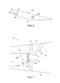
- the turbomachine 10 portion may be a diffuser section 11 (see FIG. 7 ), which is disposed downstream from a turbine section to reduce a remaining energy of combustion products exiting the turbine section before they are exhausted to the atmosphere.
- the diffuser section 11 includes an annular outer wall 12, such as a diffuser casing, and an annular inner wall 13, which may be provided as an exterior surface of a center body.
- the annular inner wall 13 is disposed within the annular outer wall 12 to define an annular pathway 14 through which a working fluid, such as the combustion products, may be directed (see FIG. 7 ).
- the diffuser section 11 further includes an aerodynamic element 20, such as a diffuser vane, which is disposed to traverse the annular pathway 14 to thereby aerodynamically interact with the working fluid.
- the aerodynamic element 20 includes a leading edge 21 defined with respect to a predominant direction of a flow of the working fluid through the pathway 14 and a trailing edge 22 defined at an opposite chordal end of the aerodynamic element 20 from the leading edge 21.
- the aerodynamic element 20 further includes a suction side 23 and a pressure side 24, which are disposed on opposite sides of the aerodynamic element 20 and respectively extend from the leading edge 21 to the trailing edge 22.
- an array of contour features 30, including individual contour features 31, is provided on the suction side 23 at a chordal location proximate to the leading edge 21 of the aerodynamic element 20.
- Each individual contour feature 31 is disposed relatively closely to another (i.e., adjacent) individual contour feature 31.
- the array of contour features 30 includes at least a first contour feature 32 and a second contour feature 33 and, in some cases, additional contour features 34.
- additional contour features 34 For purposes of clarity and brevity, the description below will simply describe a plurality of contour features 35 that includes the above-mentioned contour features.
- Each one of the plurality of contour features 35 is substantially aligned with an adjacent one of the plurality of contour features 35 along a spanwise dimension, DS, of the aerodynamic element 20.
- This alignment and the shapes of the plurality of contour features 35 encourages the generation of tangential counter-rotating vortex flows 40 (see FIG. 4 ) along the suction side 23 relative to a base flow of the working fluid that proceeds along a substantially straight path through the turbomachine 10 in a main flow direction 50 (see FIG. 4 ).
- the counter-rotating vortex flows 40 may be oriented substantially perpendicularly with respect to the main flow direction 50 of the working fluid.
- the counter-rotating vortex flows 40 combine to create an enhanced jet of entrained and energized flow 60 along the suction side 23.
- the entrained and energized flow 60 maintains boundary layer stability along the suction side 23 and thereby delays or prevents flow separation from the suction side 23 in certain applications, such as those present during high angle-of-attack inlet conditions.
- the counter-rotating vortex flows 40 are defined on either side of each enhanced jet of entrained and energized flow 60.
- the counter-rotating vortex flows 40 are provided as pairs of flow vortices.
- working fluid flows toward a mid-line of the corresponding contour feature 35 and then away from the mid-line in an elliptical pattern.
- the pairs of flow vortices may propagate in the aft axial direction or be fixed in the discrete axial positions.
- FIGS. 2 and 3 a single aerodynamic element 20 and a flow of working fluid 200 are illustrated with the assumption that the illustration is reflective of baseline or design point conditions.
- the flow of working fluid 200 has a relatively low angle-of-attack relative to the leading edge 21 and, therefore, the flow of working fluid 200 flows around the aerodynamic element 20 with relatively stable boundary layers 201.
- the flow of working fluid 200 will tend to have a relatively high angle-of-attack, as shown in FIG. 3 . Normally, this would tend to de-stabilize the boundary layers 201 and lead to flow separation but, since the suction side 23 is provided with the plurality of contour features 35, the boundary layers 201 remain relatively stable.
- the presence of the plurality of contour features 35 does not substantially affect the flow of working fluid 200 around the aerodynamic element 20 in the case illustrated in FIG. 2 .
- Each one of the plurality of contour features 35 may include a protrusion 70 disposed on the suction side 23 of the aerodynamic element 20 at a chordal location that is proximate to the leading edge 21.
- each one of the plurality of contour features 35 may have a substantially similar teardrop shape 71 with a bulbous, convex front end 710 and a narrowed, concave tail end 711.
- the teardrop shape 71 causes approaching flows 72 to diverge over a surface of the protrusion 70 to thereby generate pairs of converging flows 73 between adjacent protrusions 70.
- the pairs of converging flows 73 interact with one another and with the surrounding flows to generate the counter-rotating vortex flows 40 that propagate along the suction side 23 to thereby create the enhanced jet of entrained and energized flow 60 along the suction side 23.
- FIGS. 1-4 relate to embodiments in which each one of the plurality of contour features 35 has a similar shape
- the individual contour features 31 of the plurality of contour features 35 may have steadily varying shapes or sizes along the spanwise dimension, DS, of the aerodynamic element 20. This is illustrated in FIG. 5 with each dotted, dashed or solid line identifying an individual contour feature 31 having a unique size at steadily increasing, respective spanwise locations of the aerodynamic element 20.
- each one of the plurality of contour features 35 may be formed as a depression 80 defined in the suction side 23.
- the variations described above with reference to FIG. 5 apply here as well. That is, the shapes and sizes of the depressions 80 may be uniform or steadily varied along the spanwise dimension, DS, of the aerodynamic element 20.
- the turbomachine 10 portion is provided as a diffuser section 11 .
- the diffuser section 11 is disposed downstream from a turbine section to reduce a remaining energy of combustion products exiting the turbine section before the combustion products are exhausted to the atmosphere.
- the diffuser section 11 includes an annular outer wall 12, such as a diffuser casing, and an annular inner wall 13, which is provided as an exterior surface of center body 130.
- the annular inner wall 13 is disposed within the annular outer wall 12 to define an annular pathway 14 through which a working fluid, such as the combustion products, may be directed.
- the diffuser section 11 may further include a manway 15, which traverses the annular pathway 14 and an aerodynamic element 20, which may be provided as the diffuser vane described above or at an axial end of the center body 130 as a center body end component 131.
- the center body 130 has a substantially uniform diameter while the annular outer wall 12 has an increasing diameter along an axial dimension, DA, of the diffuser section 11. This configuration results in an area of the annular pathway 14 increasing along the axial dimension, DA, which, in turn, leads to the energy reduction of the working fluid.
- the center body end component 131 has a decreasing diameter along the axial dimension, DA, such that, along the axial length of the center body end component 131, the area of the annular pathway 14 increases at a relatively fast rate as compared to relatively slow increases in the area of the annular pathway 14 along an axial length of the center body 130 defined forwardly from the center body end component 131.
- An angular break 90 is defined at an attachment location between the center body 130 and the center body end component 131, although it is to be understood that the center body 130 and the center body end component 131 may be integrally coupled.
- the angular break 90 defines an axial location at which the annular pathway 14 increases in area along the axial dimension, DA, at the relatively fast rate.
- the array of endwall contour features 100 includes individual enwall contour features 101 and is disposed at an axial location defined proximate to the angular break 90. That is, the array of endwall contour features 100 may be disposed just forward or just aft of the angular break 90.
- the array of endwall contour features 100 may be configured substantially similarly as the array of contour features 30 described above and additional description of the same is therefore omitted.
Abstract
Description
- The subject matter disclosed herein relates to turbomachines and, more particularly, to turbine engines having aerodynamic elements configured to provide for delayed flow separation.
- A typical turbomachine, such as a gas turbine engine, includes a compressor, a combustor, a turbine and a diffuser. The compressor compresses inlet air and the combustor combusts the compressed inlet air along with fuel. The high energy products of this combustion are directed toward the turbine where they are expanded in power generation operations. The diffuser is disposed downstream from the turbine and serves to reduce the remaining energy of the combustion products before they are exhausted to the atmosphere.
- Generally, the diffuser includes an outer wall, a center body disposed within the outer wall to define an annular pathway and one or more vanes traversing the annular pathway. During baseline turbomachine operations, velocities of the combustion products flowing through the diffuser are sufficiently high and flow separation from the surfaces of the one or more vanes is not exhibited. However, at part load operations, such as gas turbine engine start-up or turn-down sequences, the combustion product velocities are reduced or high angle-of-attack conditions are in effect and flow separation tends to occur. This flow separation leads to decreased performance of the diffuser.
- According to one aspect of the invention, an aerodynamic element of a turbine engine is provided and includes leading and trailing edges defined with respect to a predominant direction of a flow of working fluid through a pathway defined through the turbine engine, suction and pressure sides oppositely extending from the leading edge to the trailing edge and at least first and second contour features proximate to the leading edge on the suction side. The first and second contour features are substantially aligned along a spanwise dimension of the aerodynamic element.
- According to another aspect of the invention, a turbine engine through which a pathway is defined is provided and includes an aerodynamic element disposed to traverse the pathway, the aerodynamic element including leading and trailing edges defined with respect to a predominant direction of a flow of working fluid through the pathway and suction and pressure sides oppositely extending from the leading edge to the trailing edge and at least first and second contour features proximate to the leading edge and to one another on the suction side. The first and second contour features are substantially aligned along a spanwise dimension of the aerodynamic element to encourage counter-rotating vortex flows oriented substantially perpendicularly with respect to a main flow direction along the suction side.
- According to yet another aspect of the invention, a turbine engine through which a pathway is defined is provided and includes an aerodynamic element disposed to traverse the pathway, the aerodynamic element including leading and trailing edges defined with respect to a predominant direction of a flow of working fluid through the pathway and suction and pressure sides oppositely extending from the leading edge to the trailing edge and contour features arrayed proximate to the leading edge and to one another on the suction side. Each of the contour features is substantially aligned with an adjacent contour feature along a spanwise dimension of the aerodynamic element to encourage counter-rotating vortex flows oriented substantially perpendicularly with respect to a main flow direction along the suction side.
- These and other advantages and features will become more apparent from the following description taken in conjunction with the drawings.
- The subject matter, which is regarded as the invention, is particularly pointed out and distinctly claimed in the claims at the conclusion of the specification. The foregoing and other features, and advantages of the invention are apparent from the following detailed description taken in conjunction with the accompanying drawings in which:
-
FIG. 1 is a side view of a portion of a turbine engine including an aerodynamic element; -
FIG. 2 is a radial view of the aerodynamic element ofFIG. 1 during baseline operations; -
FIG. 3 is a radial view of the aerodynamic element ofFIG. 1 during part load operations; -
FIG. 4 is an enlarged view of a suction side of the aerodynamic element ofFIG. 1 ; -
FIG. 5 is a radial view of the aerodynamic element ofFIG. 1 in accordance with further embodiments; -
FIG. 6 is a radial view of the aerodynamic element ofFIG. 1 in accordance with alternative embodiments; and -
FIG. 7 is a side view of a diffuser of a turbine engine including an aerodynamic element in accordance with further embodiments. - The detailed description explains embodiments of the invention, together with advantages and features, by way of example with reference to the drawings.
- In accordance with aspects of the invention, delayed flow separation in one or more portions of a turbomachine is provided for by the creation of counter-rotating vortex flows along, for example, a low-pressure surface (i.e., a suction side) of an airfoil or vane. The delayed flow separation is particularly useful during relatively high angle-of-attack conditions associated with turn-down operations of the turbomachine. The delayed flow separation is facilitated through the addition of contours, such as bumps, protrusions or indentations, to the low-pressure surface of the airfoil or vane that encourage tangential counter-rotating vortex flow structures to form along lines defined perpendicularly with respect to a main flow direction through the turbomachine of a working fluid.
- With reference to
FIGS. 1-4 , one or more portions of aturbomachine 10, such as a gas turbine engine, are provided. As an example, theturbomachine 10 portion may be a diffuser section 11 (seeFIG. 7 ), which is disposed downstream from a turbine section to reduce a remaining energy of combustion products exiting the turbine section before they are exhausted to the atmosphere. Thediffuser section 11 includes an annularouter wall 12, such as a diffuser casing, and an annularinner wall 13, which may be provided as an exterior surface of a center body. The annularinner wall 13 is disposed within the annularouter wall 12 to define anannular pathway 14 through which a working fluid, such as the combustion products, may be directed (seeFIG. 7 ). - The
diffuser section 11 further includes anaerodynamic element 20, such as a diffuser vane, which is disposed to traverse theannular pathway 14 to thereby aerodynamically interact with the working fluid. Theaerodynamic element 20 includes a leadingedge 21 defined with respect to a predominant direction of a flow of the working fluid through thepathway 14 and atrailing edge 22 defined at an opposite chordal end of theaerodynamic element 20 from the leadingedge 21. Theaerodynamic element 20 further includes asuction side 23 and apressure side 24, which are disposed on opposite sides of theaerodynamic element 20 and respectively extend from the leadingedge 21 to thetrailing edge 22. - In accordance with embodiments of the invention, an array of contour features 30, including
individual contour features 31, is provided on thesuction side 23 at a chordal location proximate to the leadingedge 21 of theaerodynamic element 20. Eachindividual contour feature 31 is disposed relatively closely to another (i.e., adjacent)individual contour feature 31. The array of contour features 30 includes at least afirst contour feature 32 and asecond contour feature 33 and, in some cases,additional contour features 34. For purposes of clarity and brevity, the description below will simply describe a plurality ofcontour features 35 that includes the above-mentioned contour features. - Each one of the plurality of
contour features 35 is substantially aligned with an adjacent one of the plurality ofcontour features 35 along a spanwise dimension, DS, of theaerodynamic element 20. This alignment and the shapes of the plurality ofcontour features 35, which will be described below, encourages the generation of tangential counter-rotating vortex flows 40 (seeFIG. 4 ) along thesuction side 23 relative to a base flow of the working fluid that proceeds along a substantially straight path through theturbomachine 10 in a main flow direction 50 (seeFIG. 4 ). Due to the shapes of the plurality ofcontour features 35, the counter-rotating vortex flows 40 may be oriented substantially perpendicularly with respect to themain flow direction 50 of the working fluid. Thus, the counter-rotating vortex flows 40 combine to create an enhanced jet of entrained and energizedflow 60 along thesuction side 23. The entrained and energized flow 60 (seeFIG. 4 ) maintains boundary layer stability along thesuction side 23 and thereby delays or prevents flow separation from thesuction side 23 in certain applications, such as those present during high angle-of-attack inlet conditions. - As shown in
FIG. 4 , thecounter-rotating vortex flows 40 are defined on either side of each enhanced jet of entrained and energizedflow 60. At various and discrete axial positions, the counter-rotating vortex flows 40 are provided as pairs of flow vortices. Within each individual flow vortex, working fluid flows toward a mid-line of thecorresponding contour feature 35 and then away from the mid-line in an elliptical pattern. The pairs of flow vortices may propagate in the aft axial direction or be fixed in the discrete axial positions. - With reference to
FIGS. 2 and 3 , a singleaerodynamic element 20 and a flow of workingfluid 200 are illustrated with the assumption that the illustration is reflective of baseline or design point conditions. As shown, the flow of workingfluid 200 has a relatively low angle-of-attack relative to the leadingedge 21 and, therefore, the flow of workingfluid 200 flows around theaerodynamic element 20 with relativelystable boundary layers 201. During part load conditions associated with, for example, turn-down operations of theturbomachine 10, the flow of workingfluid 200 will tend to have a relatively high angle-of-attack, as shown inFIG. 3 . Normally, this would tend to de-stabilize theboundary layers 201 and lead to flow separation but, since thesuction side 23 is provided with the plurality ofcontour features 35, theboundary layers 201 remain relatively stable. The presence of the plurality ofcontour features 35 does not substantially affect the flow of workingfluid 200 around theaerodynamic element 20 in the case illustrated inFIG. 2 . - Each one of the plurality of
contour features 35 may include aprotrusion 70 disposed on thesuction side 23 of theaerodynamic element 20 at a chordal location that is proximate to the leadingedge 21. As shown inFIG. 4 and, in accordance with embodiments, each one of the plurality ofcontour features 35 may have a substantiallysimilar teardrop shape 71 with a bulbous, convexfront end 710 and a narrowed,concave tail end 711. For those cases, where each one of the plurality ofcontour features 35 has a substantially similar shape as another one of the plurality ofcontour features 35, theteardrop shape 71 causes approachingflows 72 to diverge over a surface of theprotrusion 70 to thereby generate pairs ofconverging flows 73 betweenadjacent protrusions 70. Withadjacent protrusions 70 being sufficiently close to one another, the pairs ofconverging flows 73 interact with one another and with the surrounding flows to generate the counter-rotating vortex flows 40 that propagate along thesuction side 23 to thereby create the enhanced jet of entrained and energizedflow 60 along thesuction side 23. - While
FIGS. 1-4 relate to embodiments in which each one of the plurality ofcontour features 35 has a similar shape, it is to be understood that this is merely exemplary and that other embodiments exist. For example, with reference toFIG. 5 , the individual contour features 31 of the plurality ofcontour features 35 may have steadily varying shapes or sizes along the spanwise dimension, DS, of theaerodynamic element 20. This is illustrated inFIG. 5 with each dotted, dashed or solid line identifying anindividual contour feature 31 having a unique size at steadily increasing, respective spanwise locations of theaerodynamic element 20. - With reference to
FIG. 6 and, in accordance with alternative embodiments, each one of the plurality of contour features 35 may be formed as adepression 80 defined in thesuction side 23. For these alternative embodiments, it is to be understood that the variations described above with reference toFIG. 5 apply here as well. That is, the shapes and sizes of thedepressions 80 may be uniform or steadily varied along the spanwise dimension, DS, of theaerodynamic element 20. - With reference to
FIG. 7 , the particular case in which theturbomachine 10 portion is provided as adiffuser section 11 is shown. As noted above, thediffuser section 11 is disposed downstream from a turbine section to reduce a remaining energy of combustion products exiting the turbine section before the combustion products are exhausted to the atmosphere. Thediffuser section 11 includes an annularouter wall 12, such as a diffuser casing, and an annularinner wall 13, which is provided as an exterior surface ofcenter body 130. The annularinner wall 13 is disposed within the annularouter wall 12 to define anannular pathway 14 through which a working fluid, such as the combustion products, may be directed. - The
diffuser section 11 may further include amanway 15, which traverses theannular pathway 14 and anaerodynamic element 20, which may be provided as the diffuser vane described above or at an axial end of thecenter body 130 as a centerbody end component 131. As shown inFIG. 7 , thecenter body 130 has a substantially uniform diameter while the annularouter wall 12 has an increasing diameter along an axial dimension, DA, of thediffuser section 11. This configuration results in an area of theannular pathway 14 increasing along the axial dimension, DA, which, in turn, leads to the energy reduction of the working fluid. In contrast to the configuration of thecenter body 130, the centerbody end component 131 has a decreasing diameter along the axial dimension, DA, such that, along the axial length of the centerbody end component 131, the area of theannular pathway 14 increases at a relatively fast rate as compared to relatively slow increases in the area of theannular pathway 14 along an axial length of thecenter body 130 defined forwardly from the centerbody end component 131. - An
angular break 90 is defined at an attachment location between thecenter body 130 and the centerbody end component 131, although it is to be understood that thecenter body 130 and the centerbody end component 131 may be integrally coupled. Theangular break 90 defines an axial location at which theannular pathway 14 increases in area along the axial dimension, DA, at the relatively fast rate. - The annular
inner wall 13, which is provided as the exterior surface ofcenter body 130 and the centerbody end component 131, includes an array of endwall contour features 100. The array of endwall contour features 100 includes individual enwall contour features 101 and is disposed at an axial location defined proximate to theangular break 90. That is, the array of endwall contour features 100 may be disposed just forward or just aft of theangular break 90. The array of endwall contour features 100 may be configured substantially similarly as the array of contour features 30 described above and additional description of the same is therefore omitted. - While the invention has been described in detail in connection with only a limited number of embodiments, it should be readily understood that the invention is not limited to such disclosed embodiments. Rather, the invention can be modified to incorporate any number of variations, alterations, substitutions or equivalent arrangements not heretofore described, but which are commensurate with the spirit and scope of the invention. Additionally, while various embodiments of the invention have been described, it is to be understood that aspects of the invention may include only some of the described embodiments. Accordingly, the invention is not to be seen as limited by the foregoing description, but is only limited by the scope of the appended claims.
Claims (8)
- An aerodynamic element (20) of a turbine engine, comprising:leading and trailing edges (21,22) defined with respect to a predominant direction of a flow of working fluid through a pathway (14) defined through the turbine engine;suction and pressure sides (23,24) oppositely extending from the leading edge (21) to the trailing edge (22); andat least first and second contour features (32,33) proximate to the leading edge (21) on the suction side (23),the first and second contour features (32,33) being substantially aligned along a spanwise dimension of the aerodynamic element (20).
- The aerodynamic element of the turbine engine according to claim 1, wherein each of the first and second contour features (32,33) comprises one of a protrusion (70) or a depression (80).
- The aerodynamic element of the turbine engine according to claim 1 or 2, wherein each of the first and second contour features (32,33) comprises a teardrop shape (71).
- The aerodynamic element of the turbine engine according to claim 3, wherein each teardrop shaped contour feature (32,33) comprises a bulbous front end (710) and a narrowed tail end (711).
- The aerodynamic element of the turbine engine according to claim 4, wherein the bulbous front end (710) has a convex shape and the narrowed tail end (711) has a concave shape.
- The aerodynamic element of the turbine engine according to any of claims 1 to 3, wherein each of the first and second contour features (32,33) have substantially similar shapes.
- The turbine engine according to claim 1 or 2, wherein shapes or sizes of each of the contour features (32,33) steadily vary along a span of the aerodynamic element (20).
- A turbine engine (10) through which a pathway (14) is defined, comprising:an aerodynamic element (20) disposed to traverse the pathway (14), the aerodynamic element as recited in any of claims 1 to 7.
Applications Claiming Priority (1)
| Application Number | Priority Date | Filing Date | Title |
|---|---|---|---|
| US13/492,506 US20130330184A1 (en) | 2012-06-08 | 2012-06-08 | Aerodynamic element of turbine engine |
Publications (2)
| Publication Number | Publication Date |
|---|---|
| EP2672080A2 true EP2672080A2 (en) | 2013-12-11 |
| EP2672080A3 EP2672080A3 (en) | 2017-07-19 |
Family
ID=48670360
Family Applications (1)
| Application Number | Title | Priority Date | Filing Date |
|---|---|---|---|
| EP13170819.0A Withdrawn EP2672080A3 (en) | 2012-06-08 | 2013-06-06 | Aerodynamic Element of Turbine Engine |
Country Status (5)
| Country | Link |
|---|---|
| US (1) | US20130330184A1 (en) |
| EP (1) | EP2672080A3 (en) |
| JP (1) | JP2013256940A (en) |
| CN (1) | CN103485839A (en) |
| RU (1) | RU2013126226A (en) |
Cited By (2)
| Publication number | Priority date | Publication date | Assignee | Title |
|---|---|---|---|---|
| WO2019027661A1 (en) * | 2017-07-31 | 2019-02-07 | Siemens Aktiengesellschaft | Gas turbine exhaust diffuser having flow guiding elements |
| EP3643877A1 (en) * | 2018-10-22 | 2020-04-29 | Rolls-Royce plc | Ducted propulsor with airfoils having a leading edge with a deflected region |
Families Citing this family (1)
| Publication number | Priority date | Publication date | Assignee | Title |
|---|---|---|---|---|
| US11885234B2 (en) | 2021-07-30 | 2024-01-30 | Honeywell International Inc. | System and method for turbomachine with local vortex generator array |
Family Cites Families (18)
| Publication number | Priority date | Publication date | Assignee | Title |
|---|---|---|---|---|
| US1773280A (en) * | 1928-09-12 | 1930-08-19 | Rossiter S Scott | Aircraft |
| US2272358A (en) * | 1940-12-02 | 1942-02-10 | Edward C Steinhaus | Airplane propeller |
| GB789883A (en) * | 1954-08-20 | 1958-01-29 | Power Jets Res & Dev Ltd | High speed aerofoil |
| US3012709A (en) * | 1955-05-18 | 1961-12-12 | Daimler Benz Ag | Blade for axial compressors |
| US3403893A (en) * | 1967-12-05 | 1968-10-01 | Gen Electric | Axial flow compressor blades |
| US5058837A (en) * | 1989-04-07 | 1991-10-22 | Wheeler Gary O | Low drag vortex generators |
| NO313544B1 (en) * | 2001-02-02 | 2002-10-21 | Fred Olsen | Embodiments on the surface of a body |
| US6532656B1 (en) * | 2001-10-10 | 2003-03-18 | General Electric Company | Gas turbine engine compressor blade restoration method |
| EP2050929B1 (en) * | 2004-06-02 | 2009-10-21 | Rolls-Royce Deutschland Ltd & Co KG | Compressor blade, especially for the fan on plane engines |
| US7604461B2 (en) * | 2005-11-17 | 2009-10-20 | General Electric Company | Rotor blade for a wind turbine having aerodynamic feature elements |
| EP1801422B1 (en) * | 2005-12-22 | 2013-06-12 | Ziehl-Abegg AG | Fan and fan blade |
| US7413403B2 (en) * | 2005-12-22 | 2008-08-19 | United Technologies Corporation | Turbine blade tip cooling |
| JP4371171B2 (en) * | 2008-05-09 | 2009-11-25 | ダイキン工業株式会社 | Cross flow fan and air conditioner equipped with the same |
| US8011894B2 (en) * | 2008-07-08 | 2011-09-06 | General Electric Company | Sealing mechanism with pivot plate and rope seal |
| US8137072B2 (en) * | 2008-10-31 | 2012-03-20 | Solar Turbines Inc. | Turbine blade including a seal pocket |
| US20110052373A1 (en) * | 2009-09-03 | 2011-03-03 | General Electric Company | High-turning diffuser strut with flow cross-over slots |
| JP5812567B2 (en) * | 2010-02-16 | 2015-11-17 | 三菱日立パワーシステムズ株式会社 | Turbine |
| US20130224037A1 (en) * | 2011-09-13 | 2013-08-29 | Dennis Simpson | Compound airfoil |
-
2012
- 2012-06-08 US US13/492,506 patent/US20130330184A1/en not_active Abandoned
-
2013
- 2013-06-03 JP JP2013116560A patent/JP2013256940A/en active Pending
- 2013-06-06 EP EP13170819.0A patent/EP2672080A3/en not_active Withdrawn
- 2013-06-07 RU RU2013126226/06A patent/RU2013126226A/en not_active Application Discontinuation
- 2013-06-07 CN CN201310225073.6A patent/CN103485839A/en active Pending
Cited By (2)
| Publication number | Priority date | Publication date | Assignee | Title |
|---|---|---|---|---|
| WO2019027661A1 (en) * | 2017-07-31 | 2019-02-07 | Siemens Aktiengesellschaft | Gas turbine exhaust diffuser having flow guiding elements |
| EP3643877A1 (en) * | 2018-10-22 | 2020-04-29 | Rolls-Royce plc | Ducted propulsor with airfoils having a leading edge with a deflected region |
Also Published As
| Publication number | Publication date |
|---|---|
| RU2013126226A (en) | 2014-12-20 |
| EP2672080A3 (en) | 2017-07-19 |
| JP2013256940A (en) | 2013-12-26 |
| US20130330184A1 (en) | 2013-12-12 |
| CN103485839A (en) | 2014-01-01 |
Similar Documents
| Publication | Publication Date | Title |
|---|---|---|
| JP6060145B2 (en) | High camber compressor rotor blade | |
| JP6025269B2 (en) | Compressor airfoil with tip angle | |
| US9488055B2 (en) | Turbine engine and aerodynamic element of turbine engine | |
| US9279329B2 (en) | Transonic blade | |
| JP5301148B2 (en) | Turbine assembly of gas turbine engine and manufacturing method thereof | |
| JP5300874B2 (en) | Blade with non-axisymmetric platform and depression and protrusion on outer ring | |
| US7753652B2 (en) | Aero-mixing of rotating blade structures | |
| US7597544B2 (en) | Blade of axial flow-type rotary fluid machine | |
| US9957973B2 (en) | Blade with an S-shaped profile for an axial turbomachine compressor | |
| JP2017528632A (en) | Endwall configuration for gas turbine engines | |
| CA2926970C (en) | Gas turbine stator with winglets | |
| US20120315136A1 (en) | Inner peripheral surface shape of casing of axial-flow compressor | |
| JP2015081601A (en) | Gas turbine nozzle trailing edge fillet | |
| JP6624653B2 (en) | Press whirl system for gas turbine | |
| US11708762B2 (en) | Film cooling structure and turbine blade for gas turbine engine | |
| EP2672080A2 (en) | Aerodynamic Element of Turbine Engine | |
| JP2020133602A (en) | Blade and machine with the same | |
| JP2013096408A (en) | Airfoil part and method of manufacturing the same | |
| CN109154200B (en) | Airfoil and blade for a turbine engine, and corresponding method of flowing a cooling fluid | |
| EP3163020B1 (en) | Turbine rotor blade cascade, turbine stage and axial flow turbine | |
| EP3334904B1 (en) | Diffuser for a turbine engine and method of forming same | |
| JP7264685B2 (en) | Turbine vanes and turbines | |
| CN113464209A (en) | Turbine rotor blade having cooling circuit with offset ribs |
Legal Events
| Date | Code | Title | Description |
|---|---|---|---|
| PUAI | Public reference made under article 153(3) epc to a published international application that has entered the european phase |
Free format text: ORIGINAL CODE: 0009012 |
|
| AK | Designated contracting states |
Kind code of ref document: A2 Designated state(s): AL AT BE BG CH CY CZ DE DK EE ES FI FR GB GR HR HU IE IS IT LI LT LU LV MC MK MT NL NO PL PT RO RS SE SI SK SM TR |
|
| AX | Request for extension of the european patent |
Extension state: BA ME |
|
| PUAL | Search report despatched |
Free format text: ORIGINAL CODE: 0009013 |
|
| AK | Designated contracting states |
Kind code of ref document: A3 Designated state(s): AL AT BE BG CH CY CZ DE DK EE ES FI FR GB GR HR HU IE IS IT LI LT LU LV MC MK MT NL NO PL PT RO RS SE SI SK SM TR |
|
| AX | Request for extension of the european patent |
Extension state: BA ME |
|
| RIC1 | Information provided on ipc code assigned before grant |
Ipc: F01D 25/30 20060101AFI20170614BHEP Ipc: F01D 21/00 20060101ALI20170614BHEP Ipc: F04D 29/68 20060101ALI20170614BHEP Ipc: F01D 19/00 20060101ALI20170614BHEP Ipc: F01D 5/14 20060101ALI20170614BHEP Ipc: F01D 9/02 20060101ALI20170614BHEP |
|
| STAA | Information on the status of an ep patent application or granted ep patent |
Free format text: STATUS: THE APPLICATION IS DEEMED TO BE WITHDRAWN |
|
| 18D | Application deemed to be withdrawn |
Effective date: 20180103 |