EP2672072A1 - Heat shield for a low-pressure turbine steam inlet duct - Google Patents
Heat shield for a low-pressure turbine steam inlet duct Download PDFInfo
- Publication number
- EP2672072A1 EP2672072A1 EP13170222.7A EP13170222A EP2672072A1 EP 2672072 A1 EP2672072 A1 EP 2672072A1 EP 13170222 A EP13170222 A EP 13170222A EP 2672072 A1 EP2672072 A1 EP 2672072A1
- Authority
- EP
- European Patent Office
- Prior art keywords
- duct
- boss
- assembly
- shell
- segment
- Prior art date
- Legal status (The legal status is an assumption and is not a legal conclusion. Google has not performed a legal analysis and makes no representation as to the accuracy of the status listed.)
- Granted
Links
Images


Classifications
-
- F—MECHANICAL ENGINEERING; LIGHTING; HEATING; WEAPONS; BLASTING
- F01—MACHINES OR ENGINES IN GENERAL; ENGINE PLANTS IN GENERAL; STEAM ENGINES
- F01D—NON-POSITIVE DISPLACEMENT MACHINES OR ENGINES, e.g. STEAM TURBINES
- F01D25/00—Component parts, details, or accessories, not provided for in, or of interest apart from, other groups
- F01D25/24—Casings; Casing parts, e.g. diaphragms, casing fastenings
- F01D25/26—Double casings; Measures against temperature strain in casings
-
- F—MECHANICAL ENGINEERING; LIGHTING; HEATING; WEAPONS; BLASTING
- F01—MACHINES OR ENGINES IN GENERAL; ENGINE PLANTS IN GENERAL; STEAM ENGINES
- F01D—NON-POSITIVE DISPLACEMENT MACHINES OR ENGINES, e.g. STEAM TURBINES
- F01D9/00—Stators
- F01D9/06—Fluid supply conduits to nozzles or the like
- F01D9/065—Fluid supply or removal conduits traversing the working fluid flow, e.g. for lubrication-, cooling-, or sealing fluids
-
- F—MECHANICAL ENGINEERING; LIGHTING; HEATING; WEAPONS; BLASTING
- F01—MACHINES OR ENGINES IN GENERAL; ENGINE PLANTS IN GENERAL; STEAM ENGINES
- F01D—NON-POSITIVE DISPLACEMENT MACHINES OR ENGINES, e.g. STEAM TURBINES
- F01D25/00—Component parts, details, or accessories, not provided for in, or of interest apart from, other groups
- F01D25/08—Cooling; Heating; Heat-insulation
- F01D25/14—Casings modified therefor
- F01D25/145—Thermally insulated casings
-
- F—MECHANICAL ENGINEERING; LIGHTING; HEATING; WEAPONS; BLASTING
- F05—INDEXING SCHEMES RELATING TO ENGINES OR PUMPS IN VARIOUS SUBCLASSES OF CLASSES F01-F04
- F05D—INDEXING SCHEME FOR ASPECTS RELATING TO NON-POSITIVE-DISPLACEMENT MACHINES OR ENGINES, GAS-TURBINES OR JET-PROPULSION PLANTS
- F05D2220/00—Application
- F05D2220/30—Application in turbines
- F05D2220/31—Application in turbines in steam turbines
Definitions
- the present invention relates to a heat shield to improve the insulation of a steam inlet duct admitting steam to a low-pressure turbine (referred to as "LP turbine"), notably in a power station.
- LP turbine low-pressure turbine
- a low-pressure turbine is supplied by a duct with steam at a pressure of 3 to 6 bar and at a temperature of the order of 150°C and the steam needs to be as dry as possible, and it emits this steam on the outlet side at a pressure of 40 to 150 millibar and a temperature of the order of 25°C.
- dry steam is that the steam is in gaseous form and contains no (or practically no) droplets in liquid form.
- a flow of steam entering the LP turbine contains no moisture (or in other words needs to be dry, to contain no steam in the liquid state), whereas a flow of steam leaving the turbine contains between 8 and 16% moisture.
- the driest possible steam in the supply duct which preferably means steam with a moisture content of 0%.
- the proposal is therefore an assembly comprising:
- the segment thus forms a heat shield minimizing any exchange (of heat) with an environment external to the duct, in this instance with the outgoing steam.
- the segment has a shape similar to that of the duct.
- the segment is therefore also of circular cross section.
- an assembly according to the invention allows the possibility of adding a segment as defined hereinabove to an already-existing duct for example.
- the duct or at least the duct portion positioned in a zone in which it is necessary to minimize or even avoid heat exchangers, may be covered by a single segment or by several juxtaposed segments.
- the segments are easier to transport and/or to handle according to the dimensions of the duct that is to be covered or if the duct is of an irregular shape: for example if the duct has an elbow or is wider in places, etc.
- a boss means a tubular cylindrical element which is advantageously internally threaded.
- the bosses are fixed, for example, by welding, to the duct at right angles to the surface of the duct.
- the shells that make up a segment are fitted in such a way that a fixing element can be passed through an orifice in a shell and fastened into the boss.
- the fixing element is a bolted connection (i.e. a screw and a nut), which means that the screw is fixed into the boss by a screw thread and holds the shell in place by simple bearing contact.
- the shells of the segment also bear simply against the bosses around the duct.
- the bosses thus maintain a space between the segment that forms the heat shield and the surface of the duct.
- a first of the shells has a rim on one lateral edge to overlap a lateral edge of another of the shells, and preferably the first of the shells has two lateral edges, each with a rim.
- the rim may form an integral part of the shell or may be a separate element welded to the lateral edge of the shell.
- the shells are made for example of steel. If they are molded, it is preferable for the rim to form an integral part of the shell at the time of molding in order to simplify the production process.
- the shells may also advantageously be curved.
- the rim may then be formed by bending or even pressing.
- the rim is an added-on element, it has the advantage that clearance can be compensated for and contact with the rim of another shell adjusted in order to ensure sealing.
- the shells by resting against the bosses and against one another, experience a minimum level of stress when in use.
- the rim in addition, it is advantageous for the rim to belong to a shell situated further upstream in the flow of outgoing steam than the other shell or shells so as not to create a gap through which steam could infiltrate. Furthermore, the rims preferably are located along the entire length of the duct, forming a continuity.
- At least one boss, and preferably each boss, is surmounted by a cap.
- a cap makes it possible to avoid a thermal bridge at the bosses that connect the heat shield to the duct. If a bolted connection is being used, then the cap covers the head of the screw.
- the assembly comprises at least one partition between a first and a second boss, the partition being welded to at least the first boss and having a height smaller than that of the first boss.
- Such a partition creates an obstacle to a flow of fluid between the heat shield and the duct if the heat shield does not seal properly, and therefore limits thermal interactions with the duct and the steam it contains.
- the heat shield is made up of at least two juxtaposed segments
- the assembly it is preferable for the assembly to comprise an overlapping element, joined to at least one shell of a first segment of the assembly and overlapping one end of a shell of a second segment, in order to provide sealing between two consecutive segments.
- the overlapping element also advantageously rests on the shell of the second segment juxtaposed with the first. This also guarantees the shells freedom of movement in order to minimize stress in the heat shield while at the same time ensuring that the assembly is properly sealed.
- a joint means that the overlapping element may form part of the shell to which it is attached, for example is a rim extending one end of the shell just as the rim extending a lateral edge to overlap an edge of another shell of the same segment.
- the shells are produced by molding, for example, that enables the method of producing the assembly to be simplified.
- the lateral edge may also be created by bending or pressing, depending on the method chosen for creating the shells.
- the overlapping element may be a separate element and joint then means that it is attached, fixed, for example by welding, to the end of the shell.
- contact or compensation for clearance can be adjusted when the assembly is being fitted together.
- the overlapping element is T-shaped. Such a shape makes it easier to attach to a shell of a first segment while at the same time ensuring that the overlapping element rests against a shell of a second segment. Further, the overlapping element also acts as a partition at the join between the two juxtaposed segments, in order also to contribute to limiting any flow in the event of a leak following defective sealing of the heat shield.
- each segment and the duct between them define a space of constant height, and, for preference, each segment and the duct between them define a space filled with air.
- all the bosses preferably have the same height, for example thirty millimeters.
- a second aspect also proposes a turbine comprising an outer casing, an inner casing, and a steam inlet duct comprised between the outer casing and the inner casing so as to convey steam to the inner casing, wherein the turbine comprises an assembly as defined previously, and the duct of the assembly is the inlet duct admitting steam to the turbine.
- a turbine 1 comprises an outer casing 11 and an inner casing 12 covering blades (not depicted).
- At least one steam inlet duct 2 comprised between the outer casing 11 and the inner casing 12.
- the steam entering the turbine 1 is typically at a temperature of 150°C (degrees Celsius) and at a pressure of 3.5 bar; and the steam emitted at outlet, i.e. flowing out, in figure 1 , between the outer 11 and inner 12 casings is at a pressure and temperature that are far lower (of the order of 46 millibar and 25°C).
- the duct 2 comprised between the outer 11 and inner 12 casings is completely covered by a heat shield 3 made up of several segments 31, 32.
- the duct 2 is of circular cross section, as is the heat shield 3.
- Each segment 31, 32 is made up of two shells 311 and 312 or 321 and 322, which are rigid.
- the shells 311, 312, 321, 322 are preferably curved and made of steel.
- the shells 311, 312 have geometric dimensions that are similar so that the segment 31 overlaps a straight cylindrical part of the duct 2; whereas the shells 321, 322 have different geometric dimensions so that the segment 32 overlaps a curved part of the duct 2.
- Each shell 311, 312, 321, 322 has at least one fixing orifice 4 ( figure 6 ).
- Each shell 311, 312, 321, 322 rests on at least one boss 5 welded to the duct 2.
- a boss 5 is formed of a hollow cylindrical element comprising a threaded internal surface 51 (depicted in dotted line in figure 6 ).
- a fixing element 6 is, for example, a screw 61.
- the screw 61 passes through a fixing orifice 4 and screws into a boss 5.
- the fixing element 6 is covered by a cap 62 so as to avoid there being any thermal bridges at the bosses 5.
- the cap 62 is, for example, an independent component welded to the shell 311, 312, 321, 322 once the fixing element 6 has been fitted and so that the cap 62 is not in contact with the fixing element 6.
- the bosses may be beneficial for the bosses to have different heights in order to simplify the forming of the heat shield that is to cover it.
- At least some bosses 5 have a partition 63 fixed, for example by welding, to a single boss 5 and extending in the direction of another boss.
- the partition 63 is therefore situated between two bosses 5 and is attached to at least one of the two bosses between which it is located, and preferably to each of the two of them.
- the partitions 63 thus form a labyrinth creating an obstacle to any flow so as to limit exchanges of heat with the duct 2.
- the partition 63 furthermore has a height lower than that of the bosses 5 between which it is located.
- the shells 311, 312, 321, 322 have different connecting elements in order to provide sealing between two shells, 311, 312, 321, 322 of the same segment 31, 32 and between two consecutive segments 31, 32 if the heat shield 3 comprises several segments.
- the connecting element is a rim 7, situated along a lateral edge 33 of a first shell 311, 321.
- the rim 7 is obtained by bending. It is therefore in contact with the edge 34 of the second shell 312, 322 of the same segment so that the connection between the shells is a fluidtight connection.
- each segment 31, 32 comprises two shells 311, 312, 321, 322
- the first shells 311, 321 are considered to be the shells situated furthest upstream in the flow of outgoing steam, and these first shells 311, 321 therefore comprise a rim 7 along each of their two lateral edges 33.
- the connecting element is an overlapping element 8.
- the overlapping element 8 in this instance is a component separate from the shells and attached, by welding, to one end 35 of a first shell (311, 312, 321, 322) of a first segment (31, 32) which segment is, preferably and if possible, the segment situated furthest upstream in the flow of outgoing steam, in order also to guarantee a better seal; further, it overlaps an end 36 of a shell (311, 312, 321, 322) of a second segment (31, 32) which is therefore further downstream in the flow.
- connection element 7, 8 it is preferably attached to the shell 311, 312, 321, 322 that is furthest upstream in the flow of outgoing steam and overlaps the shell 311, 312, 321, 322 further downstream in this flow.
- the flow is orthogonal to the shells, i.e. if it is not possible to determine which shell would be furthest upstream, and the connecting element 7, 8 may be situated on one shell or the other with neither option preferred over the other.
- the overlapping element 8 is T-shaped so that it also forms a partition, in the manner of the partitions 63 situated between two bosses 5.
- a seal 71 for example in the form of a cover plate, is advantageously situated at the junctions between the connecting elements 7 and 8 so as to close off any gap that may have been left at this point.
Landscapes
- Engineering & Computer Science (AREA)
- Mechanical Engineering (AREA)
- General Engineering & Computer Science (AREA)
- Physics & Mathematics (AREA)
- Fluid Mechanics (AREA)
- Turbine Rotor Nozzle Sealing (AREA)
Abstract
Description
- The present invention relates to a heat shield to improve the insulation of a steam inlet duct admitting steam to a low-pressure turbine (referred to as "LP turbine"), notably in a power station.
- Traditionally, in a power station installation, a low-pressure turbine is supplied by a duct with steam at a pressure of 3 to 6 bar and at a temperature of the order of 150°C and the steam needs to be as dry as possible, and it emits this steam on the outlet side at a pressure of 40 to 150 millibar and a temperature of the order of 25°C. What is meant by "dry steam" is that the steam is in gaseous form and contains no (or practically no) droplets in liquid form. In theory, a flow of steam entering the LP turbine contains no moisture (or in other words needs to be dry, to contain no steam in the liquid state), whereas a flow of steam leaving the turbine contains between 8 and 16% moisture.
- The design of such a turbine means that the steam inlet duct is partially comprised within the casing of the turbine and thus immersed within the turbine in the flow of exiting steam.
- The result of this is that there are thermal interactions between the steam inlet duct and the flow of steam leaving the turbine, and these cause the steam arriving at the turbine to be cooled, thus increasing its moisture content.
- Now, in order to have the best possible efficiency, it is necessary to have the driest possible steam in the supply duct, which preferably means steam with a moisture content of 0%.
- It is therefore necessary to limit the thermal interactions between the steam inlet duct and the flow of steam leaving the turbine.
- The proposal is therefore an assembly comprising:
- a duct,
- and at least one segment formed of at least two rigid shells, each shell comprising at least one fixing orifice for fixing to the duct and at least one fixing element, wherein:
- the duct comprises at least one boss per shell, which boss is fixed to the duct and against which boss the shell rests, at least one orifice and one boss face one another, and the fixing element passes through the orifice facing the boss and the fixing element is fixed to the boss.
- The segment thus forms a heat shield minimizing any exchange (of heat) with an environment external to the duct, in this instance with the outgoing steam.
- Advantageously, the segment has a shape similar to that of the duct. As a duct is generally of circular cross section, the segment is therefore also of circular cross section.
- Further, an assembly according to the invention allows the possibility of adding a segment as defined hereinabove to an already-existing duct for example.
- It is also possible to juxtapose several segments one after another so as to cover the entire duct.
- Specifically, the duct, or at least the duct portion positioned in a zone in which it is necessary to minimize or even avoid heat exchangers, may be covered by a single segment or by several juxtaposed segments.
- This means that the segments are easier to transport and/or to handle according to the dimensions of the duct that is to be covered or if the duct is of an irregular shape: for example if the duct has an elbow or is wider in places, etc.
- A boss means a tubular cylindrical element which is advantageously internally threaded.
- According to one advantageous embodiment, the bosses are fixed, for example, by welding, to the duct at right angles to the surface of the duct.
- Next, the shells that make up a segment are fitted in such a way that a fixing element can be passed through an orifice in a shell and fastened into the boss. For example, the fixing element is a bolted connection (i.e. a screw and a nut), which means that the screw is fixed into the boss by a screw thread and holds the shell in place by simple bearing contact.
- The shells of the segment also bear simply against the bosses around the duct.
- The bosses thus maintain a space between the segment that forms the heat shield and the surface of the duct.
- In addition, according to an advantageous embodiment, a first of the shells has a rim on one lateral edge to overlap a lateral edge of another of the shells, and preferably the first of the shells has two lateral edges, each with a rim.
- In that way, the shells that make up a segment rest against one another. Such a connection both guarantees sealing between shells and maintains the possibility of movement.
- The rim may form an integral part of the shell or may be a separate element welded to the lateral edge of the shell.
- The shells are made for example of steel. If they are molded, it is preferable for the rim to form an integral part of the shell at the time of molding in order to simplify the production process. The shells may also advantageously be curved. The rim may then be formed by bending or even pressing.
- If the rim is an added-on element, it has the advantage that clearance can be compensated for and contact with the rim of another shell adjusted in order to ensure sealing.
- Thus, the shells, by resting against the bosses and against one another, experience a minimum level of stress when in use.
- In addition, it is advantageous for the rim to belong to a shell situated further upstream in the flow of outgoing steam than the other shell or shells so as not to create a gap through which steam could infiltrate. Furthermore, the rims preferably are located along the entire length of the duct, forming a continuity.
- According to yet another advantageous embodiment, at least one boss, and preferably each boss, is surmounted by a cap.
- The presence of a cap makes it possible to avoid a thermal bridge at the bosses that connect the heat shield to the duct. If a bolted connection is being used, then the cap covers the head of the screw.
- For preference, the assembly comprises at least one partition between a first and a second boss, the partition being welded to at least the first boss and having a height smaller than that of the first boss.
- Such a partition creates an obstacle to a flow of fluid between the heat shield and the duct if the heat shield does not seal properly, and therefore limits thermal interactions with the duct and the steam it contains.
- It is then possible to position partitions between all the bosses or just between some of them according to whether the zones of the segment are at greater or lesser risk of leakage.
- According to one embodiment whereby the heat shield is made up of at least two juxtaposed segments, it is preferable for the assembly to comprise an overlapping element, joined to at least one shell of a first segment of the assembly and overlapping one end of a shell of a second segment, in order to provide sealing between two consecutive segments. The overlapping element also advantageously rests on the shell of the second segment juxtaposed with the first. This also guarantees the shells freedom of movement in order to minimize stress in the heat shield while at the same time ensuring that the assembly is properly sealed.
- A joint means that the overlapping element may form part of the shell to which it is attached, for example is a rim extending one end of the shell just as the rim extending a lateral edge to overlap an edge of another shell of the same segment. When the shells are produced by molding, for example, that enables the method of producing the assembly to be simplified. The lateral edge may also be created by bending or pressing, depending on the method chosen for creating the shells.
- According to another method, the overlapping element may be a separate element and joint then means that it is attached, fixed, for example by welding, to the end of the shell. Thus contact or compensation for clearance can be adjusted when the assembly is being fitted together.
- According to a preferred embodiment, the overlapping element is T-shaped. Such a shape makes it easier to attach to a shell of a first segment while at the same time ensuring that the overlapping element rests against a shell of a second segment. Further, the overlapping element also acts as a partition at the join between the two juxtaposed segments, in order also to contribute to limiting any flow in the event of a leak following defective sealing of the heat shield.
- Advantagously, each segment and the duct between them define a space of constant height, and, for preference, each segment and the duct between them define a space filled with air.
- For that, all the bosses preferably have the same height, for example thirty millimeters.
- It is thus possible to benefit from the insulating properties of air while at the same time simplifying the implementation of the assembly.
- Finally, a second aspect also proposes a turbine comprising an outer casing, an inner casing, and a steam inlet duct comprised between the outer casing and the inner casing so as to convey steam to the inner casing, wherein the turbine comprises an assembly as defined previously, and the duct of the assembly is the inlet duct admitting steam to the turbine.
- Further advantages may also become apparent to a person skilled in the art for reading the examples hereinbelow, with reference to the attached figures which are given by way of entirely nonlimiting indication.
-
-
Figure 1 depicts a cross section through a turbine according to the invention. -
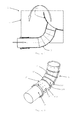
Figure 2 depicts an assembly according to the invention. -
Figure 3 depicts a heat shield according to the invention. -
Figure 4a shows a face-on view of a segment andfigure 4b shows the junction between two shells of a segment. -
Figure 5 is a perspective view of the junction between two shells of two consecutive segments. -
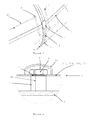
Figure 6 is a cross section through a boss with a cap. -
Figure 7 is a cross section through a T-shaped overlapping element. - Identical elements depicted in
figures 1 to 7 are identified by the same numerical references. - A
turbine 1 comprises anouter casing 11 and aninner casing 12 covering blades (not depicted). - It is supplied with steam by at least one
steam inlet duct 2 comprised between theouter casing 11 and theinner casing 12. - Steam flows in the direction of the arrows depicted in
figure 1 . - The steam entering the
turbine 1 is typically at a temperature of 150°C (degrees Celsius) and at a pressure of 3.5 bar; and the steam emitted at outlet, i.e. flowing out, infigure 1 , between the outer 11 and inner 12 casings is at a pressure and temperature that are far lower (of the order of 46 millibar and 25°C). - This is why there are problems with exchanges of heat between the
steam inlet duct 2 situated between the outer 11 and inner 12 casings. - In the example depicted in
figures 1 and 2 , theduct 2 comprised between the outer 11 and inner 12 casings is completely covered by aheat shield 3 made up ofseveral segments - In the present example, the
duct 2 is of circular cross section, as is theheat shield 3. - Each
segment shells - The
shells - The
shells segment 31 overlaps a straight cylindrical part of theduct 2; whereas theshells segment 32 overlaps a curved part of theduct 2. - Each
shell figure 6 ). - Each
shell boss 5 welded to theduct 2. - A
boss 5 is formed of a hollow cylindrical element comprising a threaded internal surface 51 (depicted in dotted line infigure 6 ). - A fixing
element 6 is, for example, ascrew 61. - The
screw 61 passes through a fixingorifice 4 and screws into aboss 5. - Furthermore, the fixing
element 6 is covered by acap 62 so as to avoid there being any thermal bridges at thebosses 5. - The
cap 62 is, for example, an independent component welded to theshell element 6 has been fitted and so that thecap 62 is not in contact with the fixingelement 6. - In the example depicted, all the
bosses 5 are identical and notably all have the same height. - In that way, they define a space of constant height between the
heat shield 3 and theduct 2 because the latter in this instance is cylindrical and regular (even though it has an elbow). - However, in other applications, if the duct has an irregular shape (such as a variable cross section for example), it may be beneficial for the bosses to have different heights in order to simplify the forming of the heat shield that is to cover it.
- At least some
bosses 5 have apartition 63 fixed, for example by welding, to asingle boss 5 and extending in the direction of another boss. - The
partition 63 is therefore situated between twobosses 5 and is attached to at least one of the two bosses between which it is located, and preferably to each of the two of them. - If there is defective sealing of the heat shield, the
partitions 63 thus form a labyrinth creating an obstacle to any flow so as to limit exchanges of heat with theduct 2. - The
partition 63 furthermore has a height lower than that of thebosses 5 between which it is located. - Finally, the
shells same segment consecutive segments heat shield 3 comprises several segments. - Between two
shells same segment rim 7, situated along alateral edge 33 of afirst shell rim 7 is obtained by bending. It is therefore in contact with theedge 34 of thesecond shell - In the embodiment depicted in which each
segment shells first shells first shells rim 7 along each of their twolateral edges 33. - Placing the
rims 7 on theshells - Between two
consecutive segments element 8. - The overlapping
element 8 in this instance is a component separate from the shells and attached, by welding, to oneend 35 of a first shell (311, 312, 321, 322) of a first segment (31, 32) which segment is, preferably and if possible, the segment situated furthest upstream in the flow of outgoing steam, in order also to guarantee a better seal; further, it overlaps anend 36 of a shell (311, 312, 321, 322) of a second segment (31, 32) which is therefore further downstream in the flow. - Thus, whatever the
connection element shell shell element - Furthermore, the overlapping
element 8 is T-shaped so that it also forms a partition, in the manner of thepartitions 63 situated between twobosses 5. - Finally, a
seal 71, for example in the form of a cover plate, is advantageously situated at the junctions between the connectingelements
Claims (9)
- An assembly comprising:- a duct (2),- and at least one segment (31, 32) formed of at least two rigid shells (311, 312, 321, 322), each shell (311, 312, 321, 322) comprising at least one fixing orifice (4) for fixing to the duct (2) and at least one fixing element (6), wherein:the duct (2) comprises at least one boss (5) per shell (311, 312, 321, 322), which boss is fixed to the duct (2) and against which boss the shell (311, 312, 321, 322) rests,at least one orifice (4) and one boss (5) face one another, andthe fixing element (6) passes through the orifice (4) facing the boss (5) andthe fixing element (6) is fixed to the boss (5).
- The assembly as claimed in claim 1, wherein a first of the shells (311, 312, 321, 322) has a rim (7) on one lateral edge (33) to overlap a lateral edge (34) of another of the shells (311, 312, 321, 322).
- The assembly as claimed in either one of claims 1 and 2, wherein each boss (5) is surmounted by a cap (62).
- The assembly as claimed in any one of claims 1 to 3, and which comprises at least one partition (63) between a first and a second boss (5), the partition (63) being welded to at least the first boss (5) and having a height smaller than that of the first boss (5).
- The assembly as claimed in any one of claims 1 to 4, and which comprises an overlapping element (8) joined to at least one shell (311, 312, 321, 322) of a first segment (31, 32) of the assembly and overlapping one end (36) of a shell (311, 312, 321, 322) of a second segment (31, 32).
- The assembly as claimed in any one of claims 1 to 5, wherein each segment (31, 32) and the duct (2) between them define a space of constant height.
- The assembly as claimed in any one of claims 1 to 6, wherein each segment (31, 32) and the duct (2) between them define a space filled with air.
- The assembly as claimed in claim 5, wherein the overlapping element (8) is T-shaped.
- A turbine (1) comprising an outer casing (11), an inner casing (12), and a steam inlet duct (2) comprised between the outer casing (11) and the inner casing (12) so as to convey steam to the inner casing (12), wherein:the turbine (1) comprises an assembly as claimed in any one of claims 1 to 7, andthe duct (2) of the assembly is the inlet duct (2) admitting steam to the turbine (1).
Applications Claiming Priority (1)
| Application Number | Priority Date | Filing Date | Title |
|---|---|---|---|
| FR1255193A FR2991375A1 (en) | 2012-06-04 | 2012-06-04 | THERMAL PROTECTION SCREEN FOR STEAM ARRIVAL IN A LOW PRESSURE TURBINE |
Publications (2)
| Publication Number | Publication Date |
|---|---|
| EP2672072A1 true EP2672072A1 (en) | 2013-12-11 |
| EP2672072B1 EP2672072B1 (en) | 2017-04-05 |
Family
ID=47191839
Family Applications (1)
| Application Number | Title | Priority Date | Filing Date |
|---|---|---|---|
| EP13170222.7A Active EP2672072B1 (en) | 2012-06-04 | 2013-06-03 | Heat shield for a low-pressure turbine steam inlet duct |
Country Status (5)
| Country | Link |
|---|---|
| US (1) | US10221723B2 (en) |
| EP (1) | EP2672072B1 (en) |
| CN (1) | CN103452607B (en) |
| FR (1) | FR2991375A1 (en) |
| RU (1) | RU2554129C2 (en) |
Cited By (1)
| Publication number | Priority date | Publication date | Assignee | Title |
|---|---|---|---|---|
| EP3115563A1 (en) * | 2015-07-06 | 2017-01-11 | General Electric Company | Insulation support system for an exhaust gas system |
Citations (5)
| Publication number | Priority date | Publication date | Assignee | Title |
|---|---|---|---|---|
| GB1118257A (en) * | 1965-06-11 | 1968-06-26 | Snecma | Improvements in arrangements for fixing thermal protection jackets in jet engine reheat chambers |
| GB1396134A (en) * | 1971-08-23 | 1975-06-04 | Carborundum Co | Protector for high temperature furnace insulation supports |
| US20050150632A1 (en) * | 2004-01-09 | 2005-07-14 | Mayer Robert R. | Extended impingement cooling device and method |
| US20100316491A1 (en) * | 2008-03-31 | 2010-12-16 | Mitsubishi Heavy Industries, Ltd. | Thermal insulation structure for structural member, and scroll structure |
| US20120047905A1 (en) * | 2010-08-27 | 2012-03-01 | Alstom Technology Ltd | Casing body through which hot gases can flow and comprising an inner heat shield |
Family Cites Families (12)
| Publication number | Priority date | Publication date | Assignee | Title |
|---|---|---|---|---|
| US2510606A (en) * | 1943-05-22 | 1950-06-06 | Lockheed Aircraft Corp | Turbine construction |
| US5127797A (en) * | 1990-09-12 | 1992-07-07 | United Technologies Corporation | Compressor case attachment means |
| US5127794A (en) * | 1990-09-12 | 1992-07-07 | United Technologies Corporation | Compressor case with controlled thermal environment |
| GB9623615D0 (en) * | 1996-11-13 | 1997-07-09 | Rolls Royce Plc | Jet pipe liner |
| JP4015282B2 (en) | 1998-06-04 | 2007-11-28 | 三菱重工業株式会社 | Flexible inlet pipe of high and medium pressure steam turbine |
| US7074009B2 (en) * | 2000-06-07 | 2006-07-11 | Borgwarner, Inc. | Casing assembly for the turbine of an exhaust turbochanger |
| GB2401658B (en) * | 2003-05-16 | 2006-07-26 | Rolls Royce Plc | Sealing arrangement |
| GB2404953A (en) * | 2003-08-15 | 2005-02-16 | Rolls Royce Plc | Blade tip clearance system |
| EP1744016A1 (en) | 2005-07-11 | 2007-01-17 | Siemens Aktiengesellschaft | Hot gas conducting cover element, shaft protection shroud and gas turbine |
| JP4755071B2 (en) | 2006-11-20 | 2011-08-24 | 三菱重工業株式会社 | Exhaust turbocharger |
| US8033722B2 (en) | 2008-08-01 | 2011-10-11 | Siemens Energy, Inc. | Thermocouple for gas turbine environments |
| US8916011B2 (en) * | 2011-06-24 | 2014-12-23 | United Technologies Corporation | Fireshield fastener hood |
-
2012
- 2012-06-04 FR FR1255193A patent/FR2991375A1/en active Pending
-
2013
- 2013-06-03 US US13/908,149 patent/US10221723B2/en active Active
- 2013-06-03 EP EP13170222.7A patent/EP2672072B1/en active Active
- 2013-06-03 RU RU2013125566/06A patent/RU2554129C2/en active
- 2013-06-04 CN CN201310217914.9A patent/CN103452607B/en active Active
Patent Citations (5)
| Publication number | Priority date | Publication date | Assignee | Title |
|---|---|---|---|---|
| GB1118257A (en) * | 1965-06-11 | 1968-06-26 | Snecma | Improvements in arrangements for fixing thermal protection jackets in jet engine reheat chambers |
| GB1396134A (en) * | 1971-08-23 | 1975-06-04 | Carborundum Co | Protector for high temperature furnace insulation supports |
| US20050150632A1 (en) * | 2004-01-09 | 2005-07-14 | Mayer Robert R. | Extended impingement cooling device and method |
| US20100316491A1 (en) * | 2008-03-31 | 2010-12-16 | Mitsubishi Heavy Industries, Ltd. | Thermal insulation structure for structural member, and scroll structure |
| US20120047905A1 (en) * | 2010-08-27 | 2012-03-01 | Alstom Technology Ltd | Casing body through which hot gases can flow and comprising an inner heat shield |
Cited By (1)
| Publication number | Priority date | Publication date | Assignee | Title |
|---|---|---|---|---|
| EP3115563A1 (en) * | 2015-07-06 | 2017-01-11 | General Electric Company | Insulation support system for an exhaust gas system |
Also Published As
| Publication number | Publication date |
|---|---|
| RU2013125566A (en) | 2014-12-10 |
| RU2554129C2 (en) | 2015-06-27 |
| FR2991375A1 (en) | 2013-12-06 |
| EP2672072B1 (en) | 2017-04-05 |
| CN103452607A (en) | 2013-12-18 |
| US10221723B2 (en) | 2019-03-05 |
| US20130323036A1 (en) | 2013-12-05 |
| CN103452607B (en) | 2015-11-18 |
Similar Documents
| Publication | Publication Date | Title |
|---|---|---|
| US9404391B2 (en) | Diffuser for the exhaust section of a gas turbine and gas turbine with such a diffuser | |
| US10801368B2 (en) | Turbocharger | |
| JP5338991B1 (en) | Turbine housing and exhaust turbine supercharger | |
| CN108292878B (en) | Cooling housing for electric motor and method of making the same | |
| US10627110B2 (en) | Combustor cooling panel, transition piece and combustor including the same, and gas turbine including combustor | |
| US20170370235A1 (en) | Transition piece, combustor provided with same, and gas turbine provided with combustor | |
| US10221723B2 (en) | Heat shield for a low-pressure turbine steam inlet duct | |
| CN105209723B (en) | Heat shielding manifold system for the middle frame housing of gas-turbine unit | |
| US20150010389A1 (en) | Pressure casing of a turbomachine | |
| JP2011038522A (en) | Turbine casing | |
| US6402203B1 (en) | Flange construction for fabric expansion joints | |
| JP2010230165A (en) | Insulating protective element of piping | |
| CN209637884U (en) | Hot gas transfer shell and gas turbine equipment | |
| JP7413382B2 (en) | An improved fire protection device designed to be placed between one end of a mounting column for an aircraft turbomachine and the cowling of the turbomachine defining an interflow compartment. | |
| RU88098U1 (en) | FIXED SUPPORT FOR INSULATED PIPELINES | |
| FIU20265031U1 (en) | Housing, heating assembly and cleaning base station | |
| KR20180076932A (en) | Protection insulation supporting apparatus of vessel | |
| US9915160B2 (en) | Steam turbine gland arrangement | |
| BR112018005031B1 (en) | TURBINE HOUSING OF A TURBOMACHINE AND TURBOMACHINE | |
| RU48623U1 (en) | ELECTRIC BOILER "BERIL-2" | |
| CN213040033U (en) | Flange protection structure for transverse pipeline and vertical pipeline | |
| JP6021786B2 (en) | Overheat reducer | |
| JP2025115148A (en) | High-temperature fluid heating and transfer device and high-temperature fluid heating device | |
| CN205534845U (en) | Area subtracts temperature layer straight tube internal fixation festival | |
| KR200330320Y1 (en) | A Structure of a Thermal Sensor Protection Pipe in the Duct of the Power Plant |
Legal Events
| Date | Code | Title | Description |
|---|---|---|---|
| PUAI | Public reference made under article 153(3) epc to a published international application that has entered the european phase |
Free format text: ORIGINAL CODE: 0009012 |
|
| AK | Designated contracting states |
Kind code of ref document: A1 Designated state(s): AL AT BE BG CH CY CZ DE DK EE ES FI FR GB GR HR HU IE IS IT LI LT LU LV MC MK MT NL NO PL PT RO RS SE SI SK SM TR |
|
| AX | Request for extension of the european patent |
Extension state: BA ME |
|
| 17P | Request for examination filed |
Effective date: 20131223 |
|
| RBV | Designated contracting states (corrected) |
Designated state(s): AL AT BE BG CH CY CZ DE DK EE ES FI FR GB GR HR HU IE IS IT LI LT LU LV MC MK MT NL NO PL PT RO RS SE SI SK SM TR |
|
| RAP1 | Party data changed (applicant data changed or rights of an application transferred) |
Owner name: GENERAL ELECTRIC TECHNOLOGY GMBH |
|
| GRAP | Despatch of communication of intention to grant a patent |
Free format text: ORIGINAL CODE: EPIDOSNIGR1 |
|
| INTG | Intention to grant announced |
Effective date: 20161116 |
|
| GRAS | Grant fee paid |
Free format text: ORIGINAL CODE: EPIDOSNIGR3 |
|
| GRAA | (expected) grant |
Free format text: ORIGINAL CODE: 0009210 |
|
| AK | Designated contracting states |
Kind code of ref document: B1 Designated state(s): AL AT BE BG CH CY CZ DE DK EE ES FI FR GB GR HR HU IE IS IT LI LT LU LV MC MK MT NL NO PL PT RO RS SE SI SK SM TR |
|
| REG | Reference to a national code |
Ref country code: GB Ref legal event code: FG4D |
|
| REG | Reference to a national code |
Ref country code: CH Ref legal event code: EP |
|
| REG | Reference to a national code |
Ref country code: AT Ref legal event code: REF Ref document number: 882034 Country of ref document: AT Kind code of ref document: T Effective date: 20170415 |
|
| REG | Reference to a national code |
Ref country code: IE Ref legal event code: FG4D |
|
| REG | Reference to a national code |
Ref country code: DE Ref legal event code: R096 Ref document number: 602013019351 Country of ref document: DE |
|
| REG | Reference to a national code |
Ref country code: FR Ref legal event code: PLFP Year of fee payment: 5 |
|
| REG | Reference to a national code |
Ref country code: NL Ref legal event code: MP Effective date: 20170405 |
|
| REG | Reference to a national code |
Ref country code: LT Ref legal event code: MG4D |
|
| REG | Reference to a national code |
Ref country code: AT Ref legal event code: MK05 Ref document number: 882034 Country of ref document: AT Kind code of ref document: T Effective date: 20170405 |
|
| PG25 | Lapsed in a contracting state [announced via postgrant information from national office to epo] |
Ref country code: NL Free format text: LAPSE BECAUSE OF FAILURE TO SUBMIT A TRANSLATION OF THE DESCRIPTION OR TO PAY THE FEE WITHIN THE PRESCRIBED TIME-LIMIT Effective date: 20170405 |
|
| PG25 | Lapsed in a contracting state [announced via postgrant information from national office to epo] |
Ref country code: ES Free format text: LAPSE BECAUSE OF FAILURE TO SUBMIT A TRANSLATION OF THE DESCRIPTION OR TO PAY THE FEE WITHIN THE PRESCRIBED TIME-LIMIT Effective date: 20170405 Ref country code: FI Free format text: LAPSE BECAUSE OF FAILURE TO SUBMIT A TRANSLATION OF THE DESCRIPTION OR TO PAY THE FEE WITHIN THE PRESCRIBED TIME-LIMIT Effective date: 20170405 Ref country code: HR Free format text: LAPSE BECAUSE OF FAILURE TO SUBMIT A TRANSLATION OF THE DESCRIPTION OR TO PAY THE FEE WITHIN THE PRESCRIBED TIME-LIMIT Effective date: 20170405 Ref country code: LT Free format text: LAPSE BECAUSE OF FAILURE TO SUBMIT A TRANSLATION OF THE DESCRIPTION OR TO PAY THE FEE WITHIN THE PRESCRIBED TIME-LIMIT Effective date: 20170405 Ref country code: NO Free format text: LAPSE BECAUSE OF FAILURE TO SUBMIT A TRANSLATION OF THE DESCRIPTION OR TO PAY THE FEE WITHIN THE PRESCRIBED TIME-LIMIT Effective date: 20170705 Ref country code: GR Free format text: LAPSE BECAUSE OF FAILURE TO SUBMIT A TRANSLATION OF THE DESCRIPTION OR TO PAY THE FEE WITHIN THE PRESCRIBED TIME-LIMIT Effective date: 20170706 Ref country code: AT Free format text: LAPSE BECAUSE OF FAILURE TO SUBMIT A TRANSLATION OF THE DESCRIPTION OR TO PAY THE FEE WITHIN THE PRESCRIBED TIME-LIMIT Effective date: 20170405 |
|
| PG25 | Lapsed in a contracting state [announced via postgrant information from national office to epo] |
Ref country code: SE Free format text: LAPSE BECAUSE OF FAILURE TO SUBMIT A TRANSLATION OF THE DESCRIPTION OR TO PAY THE FEE WITHIN THE PRESCRIBED TIME-LIMIT Effective date: 20170405 Ref country code: PL Free format text: LAPSE BECAUSE OF FAILURE TO SUBMIT A TRANSLATION OF THE DESCRIPTION OR TO PAY THE FEE WITHIN THE PRESCRIBED TIME-LIMIT Effective date: 20170405 Ref country code: BG Free format text: LAPSE BECAUSE OF FAILURE TO SUBMIT A TRANSLATION OF THE DESCRIPTION OR TO PAY THE FEE WITHIN THE PRESCRIBED TIME-LIMIT Effective date: 20170705 Ref country code: RS Free format text: LAPSE BECAUSE OF FAILURE TO SUBMIT A TRANSLATION OF THE DESCRIPTION OR TO PAY THE FEE WITHIN THE PRESCRIBED TIME-LIMIT Effective date: 20170405 Ref country code: IS Free format text: LAPSE BECAUSE OF FAILURE TO SUBMIT A TRANSLATION OF THE DESCRIPTION OR TO PAY THE FEE WITHIN THE PRESCRIBED TIME-LIMIT Effective date: 20170805 Ref country code: LV Free format text: LAPSE BECAUSE OF FAILURE TO SUBMIT A TRANSLATION OF THE DESCRIPTION OR TO PAY THE FEE WITHIN THE PRESCRIBED TIME-LIMIT Effective date: 20170405 |
|
| REG | Reference to a national code |
Ref country code: DE Ref legal event code: R097 Ref document number: 602013019351 Country of ref document: DE |
|
| PG25 | Lapsed in a contracting state [announced via postgrant information from national office to epo] |
Ref country code: RO Free format text: LAPSE BECAUSE OF FAILURE TO SUBMIT A TRANSLATION OF THE DESCRIPTION OR TO PAY THE FEE WITHIN THE PRESCRIBED TIME-LIMIT Effective date: 20170405 Ref country code: SK Free format text: LAPSE BECAUSE OF FAILURE TO SUBMIT A TRANSLATION OF THE DESCRIPTION OR TO PAY THE FEE WITHIN THE PRESCRIBED TIME-LIMIT Effective date: 20170405 Ref country code: EE Free format text: LAPSE BECAUSE OF FAILURE TO SUBMIT A TRANSLATION OF THE DESCRIPTION OR TO PAY THE FEE WITHIN THE PRESCRIBED TIME-LIMIT Effective date: 20170405 Ref country code: CZ Free format text: LAPSE BECAUSE OF FAILURE TO SUBMIT A TRANSLATION OF THE DESCRIPTION OR TO PAY THE FEE WITHIN THE PRESCRIBED TIME-LIMIT Effective date: 20170405 Ref country code: DK Free format text: LAPSE BECAUSE OF FAILURE TO SUBMIT A TRANSLATION OF THE DESCRIPTION OR TO PAY THE FEE WITHIN THE PRESCRIBED TIME-LIMIT Effective date: 20170405 Ref country code: MC Free format text: LAPSE BECAUSE OF FAILURE TO SUBMIT A TRANSLATION OF THE DESCRIPTION OR TO PAY THE FEE WITHIN THE PRESCRIBED TIME-LIMIT Effective date: 20170405 |
|
| REG | Reference to a national code |
Ref country code: CH Ref legal event code: PL |
|
| PLBE | No opposition filed within time limit |
Free format text: ORIGINAL CODE: 0009261 |
|
| STAA | Information on the status of an ep patent application or granted ep patent |
Free format text: STATUS: NO OPPOSITION FILED WITHIN TIME LIMIT |
|
| PG25 | Lapsed in a contracting state [announced via postgrant information from national office to epo] |
Ref country code: IT Free format text: LAPSE BECAUSE OF FAILURE TO SUBMIT A TRANSLATION OF THE DESCRIPTION OR TO PAY THE FEE WITHIN THE PRESCRIBED TIME-LIMIT Effective date: 20170405 Ref country code: SM Free format text: LAPSE BECAUSE OF FAILURE TO SUBMIT A TRANSLATION OF THE DESCRIPTION OR TO PAY THE FEE WITHIN THE PRESCRIBED TIME-LIMIT Effective date: 20170405 |
|
| 26N | No opposition filed |
Effective date: 20180108 |
|
| REG | Reference to a national code |
Ref country code: IE Ref legal event code: MM4A |
|
| PG25 | Lapsed in a contracting state [announced via postgrant information from national office to epo] |
Ref country code: LU Free format text: LAPSE BECAUSE OF NON-PAYMENT OF DUE FEES Effective date: 20170603 Ref country code: IE Free format text: LAPSE BECAUSE OF NON-PAYMENT OF DUE FEES Effective date: 20170603 Ref country code: LI Free format text: LAPSE BECAUSE OF NON-PAYMENT OF DUE FEES Effective date: 20170630 Ref country code: CH Free format text: LAPSE BECAUSE OF NON-PAYMENT OF DUE FEES Effective date: 20170630 |
|
| PG25 | Lapsed in a contracting state [announced via postgrant information from national office to epo] |
Ref country code: SI Free format text: LAPSE BECAUSE OF FAILURE TO SUBMIT A TRANSLATION OF THE DESCRIPTION OR TO PAY THE FEE WITHIN THE PRESCRIBED TIME-LIMIT Effective date: 20170405 |
|
| REG | Reference to a national code |
Ref country code: BE Ref legal event code: MM Effective date: 20170630 |
|
| REG | Reference to a national code |
Ref country code: FR Ref legal event code: PLFP Year of fee payment: 6 |
|
| PG25 | Lapsed in a contracting state [announced via postgrant information from national office to epo] |
Ref country code: BE Free format text: LAPSE BECAUSE OF NON-PAYMENT OF DUE FEES Effective date: 20170630 |
|
| PG25 | Lapsed in a contracting state [announced via postgrant information from national office to epo] |
Ref country code: MT Free format text: LAPSE BECAUSE OF NON-PAYMENT OF DUE FEES Effective date: 20170603 |
|
| PG25 | Lapsed in a contracting state [announced via postgrant information from national office to epo] |
Ref country code: HU Free format text: LAPSE BECAUSE OF FAILURE TO SUBMIT A TRANSLATION OF THE DESCRIPTION OR TO PAY THE FEE WITHIN THE PRESCRIBED TIME-LIMIT; INVALID AB INITIO Effective date: 20130603 |
|
| PG25 | Lapsed in a contracting state [announced via postgrant information from national office to epo] |
Ref country code: CY Free format text: LAPSE BECAUSE OF NON-PAYMENT OF DUE FEES Effective date: 20170405 |
|
| PG25 | Lapsed in a contracting state [announced via postgrant information from national office to epo] |
Ref country code: MK Free format text: LAPSE BECAUSE OF FAILURE TO SUBMIT A TRANSLATION OF THE DESCRIPTION OR TO PAY THE FEE WITHIN THE PRESCRIBED TIME-LIMIT Effective date: 20170405 |
|
| PG25 | Lapsed in a contracting state [announced via postgrant information from national office to epo] |
Ref country code: TR Free format text: LAPSE BECAUSE OF FAILURE TO SUBMIT A TRANSLATION OF THE DESCRIPTION OR TO PAY THE FEE WITHIN THE PRESCRIBED TIME-LIMIT Effective date: 20170405 |
|
| PG25 | Lapsed in a contracting state [announced via postgrant information from national office to epo] |
Ref country code: PT Free format text: LAPSE BECAUSE OF FAILURE TO SUBMIT A TRANSLATION OF THE DESCRIPTION OR TO PAY THE FEE WITHIN THE PRESCRIBED TIME-LIMIT Effective date: 20170405 |
|
| PG25 | Lapsed in a contracting state [announced via postgrant information from national office to epo] |
Ref country code: AL Free format text: LAPSE BECAUSE OF FAILURE TO SUBMIT A TRANSLATION OF THE DESCRIPTION OR TO PAY THE FEE WITHIN THE PRESCRIBED TIME-LIMIT Effective date: 20170405 |
|
| P01 | Opt-out of the competence of the unified patent court (upc) registered |
Effective date: 20230523 |
|
| REG | Reference to a national code |
Ref country code: DE Ref legal event code: R081 Ref document number: 602013019351 Country of ref document: DE Owner name: ARABELLE SOLUTIONS FRANCE, FR Free format text: FORMER OWNER: GENERAL ELECTRIC TECHNOLOGY GMBH, BADEN, CH Ref country code: DE Ref legal event code: R081 Ref document number: 602013019351 Country of ref document: DE Owner name: ARABELLE TECHNOLOGIES, FR Free format text: FORMER OWNER: GENERAL ELECTRIC TECHNOLOGY GMBH, BADEN, CH |
|
| REG | Reference to a national code |
Ref country code: GB Ref legal event code: 732E Free format text: REGISTERED BETWEEN 20250213 AND 20250219 |
|
| REG | Reference to a national code |
Ref country code: DE Ref legal event code: R081 Ref document number: 602013019351 Country of ref document: DE Owner name: ARABELLE SOLUTIONS FRANCE, FR Free format text: FORMER OWNER: ARABELLE TECHNOLOGIES, BOULOGNE-BILLANCOURT, FR |
|
| PGFP | Annual fee paid to national office [announced via postgrant information from national office to epo] |
Ref country code: DE Payment date: 20250520 Year of fee payment: 13 |
|
| PGFP | Annual fee paid to national office [announced via postgrant information from national office to epo] |
Ref country code: GB Payment date: 20250520 Year of fee payment: 13 |
|
| REG | Reference to a national code |
Ref country code: GB Ref legal event code: 732E Free format text: REGISTERED BETWEEN 20250619 AND 20250625 |
|
| PGFP | Annual fee paid to national office [announced via postgrant information from national office to epo] |
Ref country code: FR Payment date: 20250520 Year of fee payment: 13 |