BR112018005031B1 - TURBINE HOUSING OF A TURBOMACHINE AND TURBOMACHINE - Google Patents
TURBINE HOUSING OF A TURBOMACHINE AND TURBOMACHINE Download PDFInfo
- Publication number
- BR112018005031B1 BR112018005031B1 BR112018005031-8A BR112018005031A BR112018005031B1 BR 112018005031 B1 BR112018005031 B1 BR 112018005031B1 BR 112018005031 A BR112018005031 A BR 112018005031A BR 112018005031 B1 BR112018005031 B1 BR 112018005031B1
- Authority
- BR
- Brazil
- Prior art keywords
- turbine housing
- main ring
- air
- openings
- pipe
- Prior art date
Links
Images


Classifications
-
- F—MECHANICAL ENGINEERING; LIGHTING; HEATING; WEAPONS; BLASTING
- F01—MACHINES OR ENGINES IN GENERAL; ENGINE PLANTS IN GENERAL; STEAM ENGINES
- F01D—NON-POSITIVE DISPLACEMENT MACHINES OR ENGINES, e.g. STEAM TURBINES
- F01D25/00—Component parts, details, or accessories, not provided for in, or of interest apart from, other groups
- F01D25/08—Cooling; Heating; Heat-insulation
- F01D25/14—Casings modified therefor
-
- F—MECHANICAL ENGINEERING; LIGHTING; HEATING; WEAPONS; BLASTING
- F01—MACHINES OR ENGINES IN GENERAL; ENGINE PLANTS IN GENERAL; STEAM ENGINES
- F01D—NON-POSITIVE DISPLACEMENT MACHINES OR ENGINES, e.g. STEAM TURBINES
- F01D11/00—Preventing or minimising internal leakage of working-fluid, e.g. between stages
- F01D11/08—Preventing or minimising internal leakage of working-fluid, e.g. between stages for sealing space between rotor blade tips and stator
- F01D11/14—Adjusting or regulating tip-clearance, i.e. distance between rotor-blade tips and stator casing
- F01D11/20—Actively adjusting tip-clearance
- F01D11/24—Actively adjusting tip-clearance by selectively cooling-heating stator or rotor components
-
- F—MECHANICAL ENGINEERING; LIGHTING; HEATING; WEAPONS; BLASTING
- F01—MACHINES OR ENGINES IN GENERAL; ENGINE PLANTS IN GENERAL; STEAM ENGINES
- F01D—NON-POSITIVE DISPLACEMENT MACHINES OR ENGINES, e.g. STEAM TURBINES
- F01D25/00—Component parts, details, or accessories, not provided for in, or of interest apart from, other groups
- F01D25/08—Cooling; Heating; Heat-insulation
- F01D25/12—Cooling
-
- F—MECHANICAL ENGINEERING; LIGHTING; HEATING; WEAPONS; BLASTING
- F02—COMBUSTION ENGINES; HOT-GAS OR COMBUSTION-PRODUCT ENGINE PLANTS
- F02C—GAS-TURBINE PLANTS; AIR INTAKES FOR JET-PROPULSION PLANTS; CONTROLLING FUEL SUPPLY IN AIR-BREATHING JET-PROPULSION PLANTS
- F02C7/00—Features, components parts, details or accessories, not provided for in, or of interest apart form groups F02C1/00 - F02C6/00; Air intakes for jet-propulsion plants
- F02C7/12—Cooling of plants
- F02C7/16—Cooling of plants characterised by cooling medium
- F02C7/18—Cooling of plants characterised by cooling medium the medium being gaseous, e.g. air
-
- F—MECHANICAL ENGINEERING; LIGHTING; HEATING; WEAPONS; BLASTING
- F02—COMBUSTION ENGINES; HOT-GAS OR COMBUSTION-PRODUCT ENGINE PLANTS
- F02C—GAS-TURBINE PLANTS; AIR INTAKES FOR JET-PROPULSION PLANTS; CONTROLLING FUEL SUPPLY IN AIR-BREATHING JET-PROPULSION PLANTS
- F02C7/00—Features, components parts, details or accessories, not provided for in, or of interest apart form groups F02C1/00 - F02C6/00; Air intakes for jet-propulsion plants
- F02C7/24—Heat or noise insulation
-
- F—MECHANICAL ENGINEERING; LIGHTING; HEATING; WEAPONS; BLASTING
- F05—INDEXING SCHEMES RELATING TO ENGINES OR PUMPS IN VARIOUS SUBCLASSES OF CLASSES F01-F04
- F05D—INDEXING SCHEME FOR ASPECTS RELATING TO NON-POSITIVE-DISPLACEMENT MACHINES OR ENGINES, GAS-TURBINES OR JET-PROPULSION PLANTS
- F05D2240/00—Components
- F05D2240/10—Stators
- F05D2240/15—Heat shield
-
- F—MECHANICAL ENGINEERING; LIGHTING; HEATING; WEAPONS; BLASTING
- F05—INDEXING SCHEMES RELATING TO ENGINES OR PUMPS IN VARIOUS SUBCLASSES OF CLASSES F01-F04
- F05D—INDEXING SCHEME FOR ASPECTS RELATING TO NON-POSITIVE-DISPLACEMENT MACHINES OR ENGINES, GAS-TURBINES OR JET-PROPULSION PLANTS
- F05D2250/00—Geometry
- F05D2250/10—Two-dimensional
- F05D2250/14—Two-dimensional elliptical
-
- F—MECHANICAL ENGINEERING; LIGHTING; HEATING; WEAPONS; BLASTING
- F05—INDEXING SCHEMES RELATING TO ENGINES OR PUMPS IN VARIOUS SUBCLASSES OF CLASSES F01-F04
- F05D—INDEXING SCHEME FOR ASPECTS RELATING TO NON-POSITIVE-DISPLACEMENT MACHINES OR ENGINES, GAS-TURBINES OR JET-PROPULSION PLANTS
- F05D2250/00—Geometry
- F05D2250/30—Arrangement of components
- F05D2250/32—Arrangement of components according to their shape
- F05D2250/322—Arrangement of components according to their shape tangential
-
- F—MECHANICAL ENGINEERING; LIGHTING; HEATING; WEAPONS; BLASTING
- F05—INDEXING SCHEMES RELATING TO ENGINES OR PUMPS IN VARIOUS SUBCLASSES OF CLASSES F01-F04
- F05D—INDEXING SCHEME FOR ASPECTS RELATING TO NON-POSITIVE-DISPLACEMENT MACHINES OR ENGINES, GAS-TURBINES OR JET-PROPULSION PLANTS
- F05D2260/00—Function
- F05D2260/20—Heat transfer, e.g. cooling
- F05D2260/201—Heat transfer, e.g. cooling by impingement of a fluid
-
- F—MECHANICAL ENGINEERING; LIGHTING; HEATING; WEAPONS; BLASTING
- F05—INDEXING SCHEMES RELATING TO ENGINES OR PUMPS IN VARIOUS SUBCLASSES OF CLASSES F01-F04
- F05D—INDEXING SCHEME FOR ASPECTS RELATING TO NON-POSITIVE-DISPLACEMENT MACHINES OR ENGINES, GAS-TURBINES OR JET-PROPULSION PLANTS
- F05D2260/00—Function
- F05D2260/20—Heat transfer, e.g. cooling
- F05D2260/231—Preventing heat transfer
-
- Y—GENERAL TAGGING OF NEW TECHNOLOGICAL DEVELOPMENTS; GENERAL TAGGING OF CROSS-SECTIONAL TECHNOLOGIES SPANNING OVER SEVERAL SECTIONS OF THE IPC; TECHNICAL SUBJECTS COVERED BY FORMER USPC CROSS-REFERENCE ART COLLECTIONS [XRACs] AND DIGESTS
- Y02—TECHNOLOGIES OR APPLICATIONS FOR MITIGATION OR ADAPTATION AGAINST CLIMATE CHANGE
- Y02T—CLIMATE CHANGE MITIGATION TECHNOLOGIES RELATED TO TRANSPORTATION
- Y02T50/00—Aeronautics or air transport
- Y02T50/60—Efficient propulsion technologies, e.g. for aircraft
Abstract
A presente invenção refere-se a uma turbomáquina e a uma carcaça de turbina de uma turbomáquina compreendendo um dispositivo de ventilação que compreende uma pluralidade de tubulações (16?) configuradas para aspergir ar na carcaça de turbina, sendo que as tubulações estão dispostas lado a lado, cada tubulação compreende um anel principal (161) em que o ar circula, sendo que o anel principal (161) compreende aberturas (17?) configuradas para aspergir um fluxo de ar para a carcaça de turbina, sendo que cada tubulação compreende uma proteção (162) configurada para isolar o anel principal (161) de um fluxo de ar refletido da carcaça de turbina para as tubulações após ter sido aspergido para a carcaça de turbina, sendo que a proteção (162) circunda o anel principal (161) e compreende aberturas alinhadas nas aberturas do anel principal (161).The present invention relates to a turbomachine and a turbine housing of a turbomachine comprising a ventilation device comprising a plurality of pipes (16') configured to spray air into the turbine housing, the pipes being arranged side by side. On the other hand, each pipeline comprises a main ring (161) in which air circulates, the main ring (161) comprising openings (17') configured to spray a flow of air into the turbine housing, each pipeline comprising a shield (162) configured to isolate the main ring (161) from a flow of air reflected from the turbine housing to the pipelines after it has been sprayed into the turbine housing, with the shield (162) surrounding the main ring (161) and comprises openings aligned with the openings of the main ring (161).
Description
[001] A invenção refere-se a um dispositivo para ventilação de uma carcaça de turbina de uma turbomáquina, bem como uma turbomáquina que compreende esse dispositivo.[001] The invention relates to a device for ventilation of a turbine housing of a turbomachine, as well as a turbomachine comprising such a device.
[002] Em relação à Figura 1, uma turbomáquina de aeronave compreende, de forma conhecida, um rotor 1 giratório no eixo geométrico da máquina e circundado por um estator 2.[002] In relation to Figure 1, an aircraft turbomachine comprises, in a known way, a rotor 1 rotating on the geometric axis of the machine and surrounded by a
[003] O rotor 1 e o estator 2 definem entre os mesmos um jato de fluxo de gás 12 que sucessivamente passa através de um compressor de baixa pressão 3, um compressor de alta pressão 4, uma câmara de combustão 13, uma turbina de alta pressão 5 e uma turbina de baixa pressão 6.[003] The rotor 1 and the
[004] A turbina de baixa pressão 6 compreende estágios de distribuidor 8 (pás estacionárias) presos à carcaça de turbina 7 e que se alteram com estágios de pá móvel 9, presos ao rotor 1 na direção axial da máquina. A carcaça de turbina 7, que delimita o jato de fluxo de gás quente 12 é dotada de anéis passíveis de abrasão 10 voltados para a plataforma das pás móveis 9.[004] The
[005] A fim de proteger a carcaça de turbina 7 de aquecimento excessivo e garantir o bom desempenho da turbina, a turbomáquina compreende um dispositivo de ventilação 15 que compreende várias tubulações perfuradas 16 dispostas em torno da superfície externa da carcaça de turbina 7. Essas tubulações 16 são abastecidas com ar sob pressão que corresponde a uma mistura de uma corrente de ar "frio" coletada em um jato secundário periférico 30 a jusante dos compressores por meio de um ponto de coleta 14, que é um conduto situado no jato secundário 30 e uma corrente de ar "quente" coletada no jato de fluxo de gás quente 12 no compressor de alta pressão 5.[005] In order to protect the
[006] O fluxo de ar quente coletado no jato secundário 30 é transmitido para as tubulações através de um primeiro duto 17 e a corrente de ar quente coletada no jato de fluxo de gás quente 12 é transmitida para a tubulação através de um segundo duto 19. Uma válvula 18 permite o controle da permeabilidade de dois dutos de modo a controlar a temperatura da mistura de dois fluidos derivados dos dois dutos. O ar sob pressão é aspergido através de perfurações das tubulações na superfície externa da carcaça de turbina e, consequentemente, resfria a mesma.[006] The stream of hot air collected in the
[007] Uma tubulação 16 é tipicamente conformada como um anel perfurado verticalmente acima da carcaça de turbina 7 de modo a aspergir ar na carcaça de turbina 7.[007] A
[008] O dispositivo de ventilação 15 se estende em torno da turbina de baixa pressão 6.[008]
[009] Além do resfriamento do estator de carcaça de estator, o dispositivo de ventilação permite o ajuste da folga entre as pás móveis 9 e o anel passível de abrasão 10. De fato, as mudanças de temperatura da carcaça geram uma variação na folga entre as pás móveis e o anel passível de abrasão 10 devido à dilatação térmica da carcaça de estator.[009] In addition to stator housing stator cooling, the ventilation device allows adjustment of the gap between the moving blades 9 and the abrasion-
[010] Agora, a folga entre as pontas das pás móveis e os anéis passíveis de abrasão 10 é determinante para o desempenho da turbomáquina.[010] Now, the gap between the tips of the moving blades and the
[011] De fato, quanto menores forem as folgas, menor será a taxa de vazão que desvia das pás móveis 9 e dos distribuidores 8 e melhor será a eficiência da turbina de baixa pressão.[011] In fact, the smaller the gaps, the lower the flow rate that deviates from the moving blades 9 and the distributors 8 and the better the efficiency of the low pressure turbine.
[012] Consequentemente, o resfriamento da carcaça de turbina 7 tem um impacto importante no desempenho da turbina de baixa pressão e, consequentemente, da turbomáquina.[012] Consequently, the cooling of the
[013] Também são conhecidos os documentos n° US5100291, WO2013186757 e US4826397 que descrevem dispositivos de ventilação. Entretanto, as soluções propostas nesses documentos não permitem que o desempenho seja suficientemente melhorado.[013] Documents No. US5100291, WO2013186757 and US4826397 describing ventilation devices are also known. However, the solutions proposed in these documents do not allow the performance to be sufficiently improved.
[014] Um objetivo da invenção é melhorar os dispositivos de ventilação conhecidos de modo a melhorar o desempenho da turbina de baixa pressão e, portanto, da turbomáquina.[014] An objective of the invention is to improve the known ventilation devices in order to improve the performance of the low pressure turbine and, therefore, of the turbomachine.
[015] Para esta finalidade, a invenção propõe um dispositivo de ventilação de uma carcaça de turbina de turbomáquina que compreende uma pluralidade de tubulações configuradas para aspergir ar na carcaça de turbina, sendo que as tubulações estão dispostas lado a lado, cada tubulação compreende um anel principal em que o ar circula, sendo que o anel principal compreende aberturas configuradas para aspergir um fluxo de ar para a carcaça de turbina, a tubulação compreende uma proteção configurado para isolar o anel principal de um fluxo de ar refletido da carcaça de turbina para as tubulações após ter sido aspergido para a carcaça de turbina.[015] For this purpose, the invention proposes a ventilation device for a turbomachine turbine housing comprising a plurality of pipes configured to spray air into the turbine housing, the pipes being arranged side by side, each pipe comprising a main ring in which air circulates, the main ring comprising openings configured to spray a flow of air into the turbine housing, the piping comprises a shield configured to isolate the main ring from a flow of air reflected from the turbine housing to the pipes after being sprayed onto the turbine housing.
[016] A invenção é concluída, de modo vantajoso, pelos seguintes recursos, considerados individualmente ou em qualquer uma de suas combinações técnicas possíveis:[016] The invention is advantageously concluded by the following features, considered individually or in any of their possible technical combinations:
[017] A proteção circunda o anel principal e compreende aberturas alinhadas nas aberturas do anel principal.[017] The protection surrounds the main ring and comprises openings aligned with the openings of the main ring.
[018] A proteção se estende tangencialmente a partir das aberturas da tubulação, sendo que a proteção está em contato estreito com o anel principal nas aberturas.[018] The guard extends tangentially from the pipe openings, with the guard being in close contact with the main ring at the openings.
[019] A proteção se estende tangencialmente a partir da tubulação de uma zona de contato estreito entre a tubulação e a proteção, diametralmente oposta às aberturas.[019] The guard extends tangentially from the pipeline to a zone of close contact between the pipeline and the guard, diametrically opposite the openings.
[020] A seção transversal da proteção tem o formato de uma elipse.[020] The cross section of the protection has the shape of an ellipse.
[021] A elipse tem um eixo geométrico principal duas vezes maior que o diâmetro da seção transversal da tubulação.[021] The ellipse has a principal geometric axis twice the diameter of the pipe cross section.
[022] Uma cavidade definida entre a proteção e a tubulação é preenchida com ar ou argônio.[022] A cavity defined between the shield and the pipe is filled with air or argon.
[023] A invenção também se refere a uma turbomáquina que compreende uma turbina e um dispositivo de ventilação de carcaça de turbina de acordo com a invenção.[023] The invention also relates to a turbomachine comprising a turbine and a turbine housing ventilation device according to the invention.
[024] Outros recursos, objetivos e vantagens da invenção serão revelados pela seguinte descrição, que é puramente ilustrativa e não limitadora, e que precisam ser lidos em referência aos desenhos em anexo em que, diferente da Figura 1, ilustram uma vista esquemática de uma turbomáquina do tipo já discutido: - A Figura 2 ilustra uma disposição de tubulações de um tipo conhecido do dispositivo de ventilação; - A Figura 3 ilustra uma disposição das tubulações em um dispositivo de ventilação de acordo com uma realização da invenção; - A Figura 4 ilustra uma tubulação de um dispositivo de ventilação de acordo com uma realização da invenção.[024] Other features, objectives and advantages of the invention will be revealed by the following description, which is purely illustrative and not limiting, and which need to be read with reference to the attached drawings in which, unlike Figure 1, they illustrate a schematic view of a turbomachine of the type already discussed: - Figure 2 illustrates a piping arrangement of a known type of ventilation device; - Figure 3 illustrates an arrangement of pipes in a ventilation device according to an embodiment of the invention; - Figure 4 illustrates a piping of a ventilation device according to an embodiment of the invention.
[025] Em todas as Figuras, elementos semelhantes possuem símbolos de referência idênticos.[025] In all Figures, similar elements have identical reference symbols.
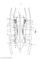
[026] É mostrado na Figura 1 um dispositivo de ventilação de um tipo conhecido que compreende tubulações 16 que estão tipicamente na forma de anéis perfurados verticalmente acima da carcaça de turbina 7 de modo a aspergir ar na carcaça de turbina 7.[026] Shown in Figure 1 is a ventilation device of a known
[027] Em relação à Figura 2, o Requerente observou que um fluxo de ar aspergido para a carcaça de turbina 7 será aquecido através de contato com a mesma.[027] In relation to Figure 2, the Applicant noted that a stream of air sprayed into the
[028] Por essa razão, uma corrente de ar quente de pós-impacto F2 é refletida da carcaça de turbina 7 para as tubulações de modo que as mesmas aqueçam o último e, então, o fluxo de ar frio F1 emerge da mesma.[028] For that reason, a stream of hot air of post-impact F2 is reflected from the
[029] Portanto, considerando que várias tubulações estão dispostas lado a lado, o ar quente derivado do impacto de ar frio na carcaça de turbina aquecerá a tubulação contígua (ou tubulações contíguas), o que reduz o desempenho de resfriamento da carcaça.[029] Therefore, considering that several pipes are arranged side by side, the hot air derived from the impact of cold air on the turbine housing will heat the adjacent pipe (or adjacent pipes), which reduces the cooling performance of the housing.
[030] A fim de evitar esse problema, o Requerente modificou as tubulações da Figura 2 e da Figura 1 (ainda posicionadas no mesmo local na turbomáquina da Figura 1) em relação à Figura 3 e propõe um dispositivo de ventilação que compreende uma pluralidade de tubulações 16’, sendo que cada uma compreende um anel principal 161 em que um fluxo de ar circula e uma proteção 162 configurada para isolar o anel principal de um fluxo de ar refletido da carcaça de turbina 7 para as tubulações 16’ após ter sido aspergido para a carcaça de turbina 7.[030] In order to avoid this problem, the Applicant modified the pipes of Figure 2 and Figure 1 (still positioned in the same place in the turbomachine of Figure 1) in relation to Figure 3 and proposes a ventilation device that comprises a plurality of pipes 16', each comprising a
[031] O anel principal 161 compreende aberturas 17’ configuradas para aspergir um fluxo de ar para a carcaça de turbina 7.[031] The
[032] Conforme pode ser visto na Figura 3, um fluxo de ar F2 derivado da carcaça de turbina 7 após ter impactado a carcaça de turbina é refletido para as tubulações. Através de comparação com o mesmo fluxo de ar na realização do estado da técnica (consultar Figura 2), o mesmo está mais distante do anel principal.[032] As can be seen in Figure 3, an air flow F2 derived from the
[033] Devido a essa proteção 162, zonas inoperantes inacessíveis pela corrente de pós-impacto F2 são criadas em torno do anel principal. Essas zonas inoperantes isolam termicamente o anel principal 161 reduzindo, em relação ao estado da técnica, a temperatura do fluxo de ar frio F1 e melhorando a eficácia do dispositivo de resfriamento.[033] Due to this
[034] A proteção pode circundar completamente o anel principal e compreender aberturas alinhadas nas aberturas do anel principal.[034] The guard may completely encircle the main ring and comprise openings aligned with the openings of the main ring.
[035] Vantajosamente, a proteção 162 se estende tangencialmente a partir de aberturas da tubulação, sendo que a proteção está em contato estreito com o anel principal nas aberturas. Tal contato possibilita limitar a perda de carga durante a expulsão de ar do anel principal para a carcaça de turbina 7.[035] Advantageously, the
[036] De modo semelhante, vantajosamente, a proteção se estende tangencialmente a partir da tubulação de uma zona de contato estreito entre a tubulação e a proteção, diametralmente oposta às aberturas. Tal contato possibilita limitar o volume externo e possibilita obter vantagem do ar frio que circula no jato secundário acima do mesmo e troca através de radiação com a nacela que, para a sua parte, é fria.[036] Similarly, advantageously, the shield extends tangentially from the pipe to a zone of close contact between the pipe and shield, diametrically opposite the openings. Such contact makes it possible to limit the external volume and makes it possible to take advantage of the cold air that circulates in the secondary jet above it and exchanges through radiation with the nacelle which, for its part, is cold.
[037] A fim de limitar o volume radial das proteções, o último tem o formato de uma elipse. Também é possível fornecer um formato retangular ou um formato oval.[037] In order to limit the radial volume of the guards, the latter is shaped like an ellipse. It is also possible to provide a rectangular shape or an oval shape.
[038] No caso de um formato elíptico, conforme pode ser visto na Figura 4, a elipse tem um eixo geométrico principal duas vezes maior que o diâmetro D da seção transversal da tubulação.[038] In the case of an elliptical shape, as can be seen in Figure 4, the ellipse has a principal geometric axis twice as large as the diameter D of the pipe cross section.
[039] A proteção 162 pode ser do mesmo material que a tubulação, por exemplo, uma liga a base de níquel e cromo.[039]
[040] A proteção pode ser oca, a cavidade 163 definida entre a proteção e a tubulação pode ser preenchida com ar ou argônio. Entretanto, o ar será preferido, visto que o mesmo é um melhor isolante e tem um custo mais baixo.[040] The shield can be hollow, the
Claims (7)
Applications Claiming Priority (3)
| Application Number | Priority Date | Filing Date | Title |
|---|---|---|---|
| FR1558619A FR3041037B1 (en) | 2015-09-15 | 2015-09-15 | DEVICE FOR VENTILATION OF A TURBINE HOUSING OF A TURBOMACHINE |
| FR1558619 | 2015-09-15 | ||
| PCT/FR2016/052292 WO2017046499A1 (en) | 2015-09-15 | 2016-09-12 | Device for ventilation of a turbomachine turbine casing |
Publications (2)
| Publication Number | Publication Date |
|---|---|
| BR112018005031A2 BR112018005031A2 (en) | 2018-10-02 |
| BR112018005031B1 true BR112018005031B1 (en) | 2022-08-09 |
Family
ID=54329831
Family Applications (1)
| Application Number | Title | Priority Date | Filing Date |
|---|---|---|---|
| BR112018005031-8A BR112018005031B1 (en) | 2015-09-15 | 2016-09-12 | TURBINE HOUSING OF A TURBOMACHINE AND TURBOMACHINE |
Country Status (9)
| Country | Link |
|---|---|
| US (1) | US10677093B2 (en) |
| EP (1) | EP3350417B2 (en) |
| JP (1) | JP6864690B2 (en) |
| CN (1) | CN108026780B (en) |
| BR (1) | BR112018005031B1 (en) |
| CA (1) | CA2997939C (en) |
| FR (1) | FR3041037B1 (en) |
| RU (1) | RU2691241C1 (en) |
| WO (1) | WO2017046499A1 (en) |
Families Citing this family (2)
| Publication number | Priority date | Publication date | Assignee | Title |
|---|---|---|---|---|
| FR3068732B1 (en) * | 2017-07-06 | 2020-06-26 | Safran Aircraft Engines | COOLING DEVICE |
| FR3081927B1 (en) * | 2018-05-30 | 2020-11-20 | Safran Aircraft Engines | TURBOMACHINE CASING COOLING SYSTEM |
Family Cites Families (12)
| Publication number | Priority date | Publication date | Assignee | Title |
|---|---|---|---|---|
| SU452593A1 (en) * | 1973-09-13 | 1974-12-05 | Всесоюзный Научно-Исследовательский И Проектный Институт По Очистке Технологических Газов,Сточных Вод И Использованию Вторичных Энергоресурсов Предприятий Черной Металлургии | Blast Furnace Tuyere |
| US4826397A (en) * | 1988-06-29 | 1989-05-02 | United Technologies Corporation | Stator assembly for a gas turbine engine |
| US5100291A (en) * | 1990-03-28 | 1992-03-31 | General Electric Company | Impingement manifold |
| FR2750451B1 (en) * | 1996-06-27 | 1998-08-07 | Snecma | DEVICE FOR BLOWING GAS ADJUSTING GAMES IN A TURBOMACHINE |
| FR2766232B1 (en) | 1997-07-18 | 1999-08-20 | Snecma | CIRCULAR HOUSING COOLING OR HEATING DEVICE |
| FR2829176B1 (en) * | 2001-08-30 | 2005-06-24 | Snecma Moteurs | STATOR CASING OF TURBOMACHINE |
| US8979477B2 (en) * | 2011-03-09 | 2015-03-17 | General Electric Company | System for cooling and purging exhaust section of gas turbine engine |
| JP5222384B2 (en) * | 2011-09-09 | 2013-06-26 | 三菱重工業株式会社 | gas turbine |
| ITTO20120519A1 (en) * | 2012-06-14 | 2013-12-15 | Avio Spa | GAS TURBINE FOR AERONAUTICAL MOTORS |
| US9341074B2 (en) * | 2012-07-25 | 2016-05-17 | General Electric Company | Active clearance control manifold system |
| US9068474B2 (en) * | 2013-01-25 | 2015-06-30 | GM Global Technology Operations LLC | Turbine housing |
| US20170114667A1 (en) * | 2015-10-23 | 2017-04-27 | General Electric Company | Active clearance control with integral double wall heat shielding |
-
2015
- 2015-09-15 FR FR1558619A patent/FR3041037B1/en active Active
-
2016
- 2016-09-12 CN CN201680052926.2A patent/CN108026780B/en active Active
- 2016-09-12 WO PCT/FR2016/052292 patent/WO2017046499A1/en active Application Filing
- 2016-09-12 CA CA2997939A patent/CA2997939C/en active Active
- 2016-09-12 RU RU2018113308A patent/RU2691241C1/en active
- 2016-09-12 EP EP16774530.6A patent/EP3350417B2/en active Active
- 2016-09-12 BR BR112018005031-8A patent/BR112018005031B1/en active IP Right Grant
- 2016-09-12 JP JP2018532830A patent/JP6864690B2/en active Active
- 2016-09-12 US US15/760,219 patent/US10677093B2/en active Active
Also Published As
| Publication number | Publication date |
|---|---|
| EP3350417A1 (en) | 2018-07-25 |
| US20180258793A1 (en) | 2018-09-13 |
| EP3350417B1 (en) | 2019-12-11 |
| BR112018005031A2 (en) | 2018-10-02 |
| FR3041037B1 (en) | 2018-08-17 |
| EP3350417B2 (en) | 2023-06-21 |
| RU2691241C1 (en) | 2019-06-11 |
| CA2997939A1 (en) | 2017-03-23 |
| JP2018530707A (en) | 2018-10-18 |
| CA2997939C (en) | 2023-09-26 |
| FR3041037A1 (en) | 2017-03-17 |
| JP6864690B2 (en) | 2021-04-28 |
| US10677093B2 (en) | 2020-06-09 |
| CN108026780A (en) | 2018-05-11 |
| CN108026780B (en) | 2020-06-30 |
| WO2017046499A1 (en) | 2017-03-23 |
Similar Documents
| Publication | Publication Date | Title |
|---|---|---|
| US7334412B2 (en) | Cooling air and injected liquid system for gas turbine blades | |
| BR102016028354A2 (en) | METHOD OF COOLING GAS TURBINE ENGINE | |
| BR102016005277A2 (en) | system for cooling a turbine and for cooling a turbine engine | |
| US8256229B2 (en) | Rear hub cooling for high pressure compressor | |
| CN204253116U (en) | For the protective housing sections of combustion gas turbine shell | |
| US10012101B2 (en) | Seal system for a gas turbine | |
| JP5865204B2 (en) | Axial turbine and power plant | |
| BR102016002830A2 (en) | engine component | |
| EP3336312A1 (en) | Cooling assembly for a turbine assembly | |
| JP2015078621A5 (en) | ||
| US20150089957A1 (en) | Device for connecting a fixed portion of a turbine engine and a distributor foot of a turbine engine turbine | |
| JP6906907B2 (en) | Cooling structure for fixed blades | |
| JP2017025910A (en) | Cooling structure for stationary blade | |
| BR102016027237A2 (en) | ENGINE COMPONENT FOR GAS TURBINE ENGINE | |
| JP2016098823A (en) | Systems and methods for rotor rim impingement cooling | |
| CN103321692A (en) | Thermal isolation apparatus | |
| BR112018005031B1 (en) | TURBINE HOUSING OF A TURBOMACHINE AND TURBOMACHINE | |
| EP3239476B1 (en) | Case clearance control system and corresponding gas turbine engine | |
| GB655304A (en) | Improvements in or relating to turbine cooling systems | |
| CN109906309B (en) | Cooling device for turbine of turbomachine | |
| JP2014066247A (en) | Cooling method and system for cooling blades of at least one blade row in rotary flow machine | |
| US10294810B2 (en) | Heat exchanger seal segment for a gas turbine engine | |
| US20190128135A1 (en) | System and method of controlling tip clearance in a shroud assembly for a bladed disc | |
| CN107795383B (en) | A kind of gas turbine cooling air distribution system | |
| US20170226862A1 (en) | Fluid cooled rotor for a gas turbine |
Legal Events
| Date | Code | Title | Description |
|---|---|---|---|
| B06U | Preliminary requirement: requests with searches performed by other patent offices: procedure suspended [chapter 6.21 patent gazette] | ||
| B09A | Decision: intention to grant [chapter 9.1 patent gazette] | ||
| B16A | Patent or certificate of addition of invention granted [chapter 16.1 patent gazette] |
Free format text: PRAZO DE VALIDADE: 20 (VINTE) ANOS CONTADOS A PARTIR DE 12/09/2016, OBSERVADAS AS CONDICOES LEGAIS |