EP2672037A1 - Loading system - Google Patents
Loading system Download PDFInfo
- Publication number
- EP2672037A1 EP2672037A1 EP13002952.3A EP13002952A EP2672037A1 EP 2672037 A1 EP2672037 A1 EP 2672037A1 EP 13002952 A EP13002952 A EP 13002952A EP 2672037 A1 EP2672037 A1 EP 2672037A1
- Authority
- EP
- European Patent Office
- Prior art keywords
- frame
- loading
- tilting
- stacking
- leg
- Prior art date
- Legal status (The legal status is an assumption and is not a legal conclusion. Google has not performed a legal analysis and makes no representation as to the accuracy of the status listed.)
- Granted
Links
- 238000010276 construction Methods 0.000 description 2
- 238000006073 displacement reaction Methods 0.000 description 1
- 238000000034 method Methods 0.000 description 1
- 238000005192 partition Methods 0.000 description 1
- 230000037081 physical activity Effects 0.000 description 1
- 230000006641 stabilisation Effects 0.000 description 1
- 238000011105 stabilization Methods 0.000 description 1
- 239000003381 stabilizer Substances 0.000 description 1
Images


Classifications
-
- E—FIXED CONSTRUCTIONS
- E04—BUILDING
- E04G—SCAFFOLDING; FORMS; SHUTTERING; BUILDING IMPLEMENTS OR AIDS, OR THEIR USE; HANDLING BUILDING MATERIALS ON THE SITE; REPAIRING, BREAKING-UP OR OTHER WORK ON EXISTING BUILDINGS
- E04G5/00—Component parts or accessories for scaffolds
- E04G5/004—Storage and transport racks for scaffolding components
Definitions
- the invention relates to a loading system, in particular for loading components of a scaffolding.
- scaffolding currently known elements of a scaffolding, in particular scaffolding frames, by hand, for example, loaded from a warehouse on a loading area of a truck.
- the scaffolding frames are usually made of 120 scaffolding frames.
- a loading system in which a lifting element for lifting, lateral displacement and lowering of a handling vehicle has.
- a lifting element for lifting, lateral displacement and lowering of a handling vehicle has.
- Such a system is used for example in rail-based vehicles.
- a device for transferring tubular objects between tube racks and a drill floor is described. To accomplish this, a tube loading device is lifted with a carriage that moves the tube into a groove in which the carriage is capable of absorbing tube impact forces without damaging the tube ends or carriage drive system.
- the loading system consists of a tilting station and a stacking rack, wherein the stacking rack has a first storage area for loading parts and an at least approximately at right angles thereto arranged first laying area for loading parts having.
- the tilting station has a second footprint for the stacking rack and an at least approximately at right angles thereto arranged second laying surface for the stacking rack.
- the stacking rack can be used in the tilting station in such a way that the shelves and laying surfaces are aligned in pairs at least roughly parallel to one another.
- the loading station further comprises a stationary base frame and an L-shaped tilting element.
- the tilting element preferably provides the second footprint and the second laying surface in an area embraced by the L.
- the tilting element is fixed by means of an actuator rotatably about an axis on the base frame, so that the tilting element can be tilted by about 90 ° from a loading position to a discharge position.
- the shelves are approximately horizontally aligned.
- the laying surfaces are aligned approximately horizontally.
- the base frame also has supports which act in a substantially vertical direction and support the tilting element in the respective position.
- scaffolding frames in the form of lying stacking racks are used with a forklift from a warehouse in the dumping station and loaded from there standing on the loading area.
- the tilting station is tilted from the unloading position by 90 ° in the loading position.
- the finished loaded truck can transport the scaffolding frames after loading.
- the stacking racks are successively tilted by the tilting station in the loading position.
- the loaded truck returns to the warehouse, for example, six stacking racks can be successively loaded onto the tilting station in the loading position, rotated by the tilting station into the horizontal unloading position and then cleared by the forklift truck into the warehouse.
- the forklift itself has the tilting station.
- the loading system provides a separate loading box for scaffolding components, in which, for example, shelves, backrests, builders and diagonals of a scaffolding can be loaded secured.
- the invention reduces the comparable loading time in the illustrated variant to one hour compared to five hours after the known manual loading.
- Another advantage is that a complete load of scaffolding frames in the stack racks can be preloaded in a specific order. This forced loading causes the When the scaffolding is dismantled, the scaffolding components must be sorted into the boxes by the fitters in the same order as they are to be taken in reverse order on the next scaffolding setup. Sorting in the warehouse is also simplified. On the construction site can be unloaded with a Krahn, without having to search for retaining walls or to stack the components by hand. The reconstruction of the scaffold is significantly accelerated when removing the stationary components from the stack racks.
- the physical activity during loading and unloading is significantly reduced by the loading system according to the invention.
- FIG. 1 to Fig. 12 an embodiment of a loading system according to the invention with tilting station 10, stacking rack 30 and loading box 50 is shown. Not all reference numerals are entered in all figures, in order to maintain a good overview.
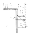
- Fig. 1 and Fig. 2 is a tilting station 10 without inserted stacking rack in loading position ( Fig. 1 ) or unloading position ( Fig. 2 ).
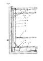
- Fig. 9 is shown as an extract from the tilting station separately a tilting element 14 with inserted stacking frame 30.
- the tilting station 10 acc. Fig. 1 and Fig. 2 has a support end 23 and a Whitneyde 24. On the support end 23 is a vertically acting support 21 is arranged, which is intended to support the tilting element 14 in the unloading position ,
- a vertical hinge leg 15 is arranged and supported to the supporting end 23 diagonally on the base plate 13.
- the joint leg 15 has at its free end a hinge 16 in which the tilting element 14 is rotatably received.
- a lifting cylinder 19 hingedly connected to the base plate 23. The joint distance is about half a joint leg length.
- the joint leg 15 Facing the support end 24, the joint leg 15 has a horizontally acting support element 25, against which the tilting element 14 is intended to strike in its loading position. In the loading position, the tilting element 14 is the entire positioning end 24 as a horizontal support surface available.
- the tilting element 14 has an L-shaped inner area facing on a long Leletonel 17, a second laying surface 12 and on a short adjusting leg 18, a second footprint 11 for the stacking rack (in Fig. 1 . Fig. 2 not shown). Adjacent to the laying or adjusting surfaces, guide rails 26 are arranged, which restrict mobility of the stacking frame on the tilting element 14. Approximately in the middle of the lifting cylinder 19 is articulated 27 connected to the Leskyel 17. From this articulated connection to Adjusting leg 18 toward the cylinder distance 20 corresponding far away there is a hinged connection 16 to the joint leg 15th
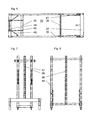
- FIG. 3 shows the stacking rack 30 in a side view on a broadside on his, as a base of a U to look at Le furnishedel 35 (below) lying with a right angle arranged for this short adjusting leg 33 (right) and an equi-short upper leg 34 (left).
- the 4 and FIG. 5 show sectional views through the U from the inside to the short legs 33, 34, wherein in the interior of the U on the Le furnishedel 35 arranged perforated rails 36, 37 can be seen.
- the upper leg 34 is supported against the Lescherel 35 with supporting in frame longitudinally long diagonal 40.
- the adjusting leg 33 is supported with short diagonals 41 against the Leseizedel 35.
- the perforated rails 36, 37 are shown separately in perforated rail holders 38, 39 ( FIGS. 7 and 8 ), in which Fig. 7 an upper hole rail holder 38 shows and Fig. 8 a lower hole rail holder 39.
- the aligned in the frame longitudinal direction long diagonal 40 are connected in an inner region with the hole rail holder 38 and thus indirectly support the upper leg 3.
- More stabilizers 46 connect gem.
- Fig. 6 the upper leg 34 at least indirectly with the laying leg 35 in a horizontal frame transverse direction.
- the upper hole rail 37 is placed inside the U-shaped stacking frame 30 (in Fig. 6 not visible). When loading it is subsequently used and mounted with a holder 43 on the upper leg 34.
- the hole rail holder 38, 39 support in the stacking frame 30 to be used frame sections (not shown) laterally; top from the inside 38 and bottom / middle. depending on the arrangement of the lower hole rail holder 39 - from the outside.
- For stabilization 39 further diagonal 45 are arranged in a lower region of the lower hole rail holder, which extend in a frame transverse direction to a lower end of the lower perforated rail 36 back.
- the perforated rails 36, 37 and a securing bar 42 arranged at right angles to the perforated rails in a longitudinal direction of the stacking rack 30 are detachably connected to each other.
- the safety bar 42 closes after loading the stacking rack 30 whose U almost completely.
- the scaffolding frames of a partially loaded stacking frame 30 can be secured by means of the securing rail attached to the perforated rails 36, 37, as it can be connected to the perforated rails in the interior of the U parallel to the scaffolding.
- Fig. 9 is a parallel arrangement of shelves 11, 31 and of laying surfaces 12, 32 recognizable when the stacking frame 30 is inserted into the tilting element 14.
- a loading box 50 is shown for various scaffolding components.
- the loading box 50 may be in accordance with the in Fig. 10 Plan view shown in sections 51 are divided.
- the sections 51 are separated by dividers 52 or partitions. Seen in the direction of travel fuse walls 53 limit the loading box.
- Fig. 11 is an open transversely to the direction of construction of the loading box 50 recognizable, in which case security walls from, for example, wooden planks are used.
- a receptacle for the forks of a forklift is provided transverse to the direction of travel of the truck to be loaded with the loading box.
Landscapes
- Engineering & Computer Science (AREA)
- Architecture (AREA)
- Mechanical Engineering (AREA)
- Civil Engineering (AREA)
- Structural Engineering (AREA)
- Warehouses Or Storage Devices (AREA)
Abstract
Description
Die Erfindung betrifft ein Verladesystem, insbesondere für das Verladen von Bauelementen eines Baugerüstes.The invention relates to a loading system, in particular for loading components of a scaffolding.
Im Gerüstbau werden derzeit bekannte Elemente eines Baugerüsts, insbesondere Gerüstrahmen, von Hand beispielsweise aus einem Lager auf eine Ladefläche eines Lastwagens verladen. Die Gerüstrahmen werden meist von 120 Gerüstrahmen.In scaffolding currently known elements of a scaffolding, in particular scaffolding frames, by hand, for example, loaded from a warehouse on a loading area of a truck. The scaffolding frames are usually made of 120 scaffolding frames.
In der
In der
In der
Die beschriebenen Systeme sind entweder zu unhandlich oder erfordern einen größeren technischen Aufwand. Vor diesem Hintergrund ist es Aufgabe der vorliegenden Erfindung ein verbessertes Verladesystem bereitzustellen, mit dem das Verladeverfahren beschleunigt und die Arbeitsbelastung der Monteure verringert wird.The systems described are either too cumbersome or require a greater technical effort. Against this background, it is an object of the present invention to provide an improved loading system with which the loading process is accelerated and the workload of the fitters is reduced.
Die Aufgabe wird gelöst durch ein Verladesystem mit den Merkmalen des Patentanspruchs 1.The object is achieved by a loading system having the features of patent claim 1.
Vorteilhafte Ausführungsformen sind in den Unteransprüchen angegeben.Advantageous embodiments are specified in the subclaims.
Das erfindungsgemäße Verladesystem besteht aus einer Kippstation und einem Stapelgestell, wobei das Stapelgestell eine erste Stellfläche für Verladeteile und eine zumindest annähernd rechtwinklig dazu angeordnete erste Legefläche für Verladeteile aufweist. Die Kippstation weist eine zweite Stellfläche für das Stapelgestell und eine zumindest annähernd rechtwinklig dazu angeordnete zweite Legefläche für das Stapelgestell auf. Das Stapelgestell ist derart in der Kippstation einsetzbar, dass die Stellflächen und Legeflächen paarweise zumindest grob parallel zueinander ausgerichtet sind.The loading system according to the invention consists of a tilting station and a stacking rack, wherein the stacking rack has a first storage area for loading parts and an at least approximately at right angles thereto arranged first laying area for loading parts having. The tilting station has a second footprint for the stacking rack and an at least approximately at right angles thereto arranged second laying surface for the stacking rack. The stacking rack can be used in the tilting station in such a way that the shelves and laying surfaces are aligned in pairs at least roughly parallel to one another.
Die Verladestation weist ferner einen ortsfesten Grundrahmen und ein L-förmiges Kippelement auf. Das Kippelement stellt dabei vorzugsweise in einem durch das L umarmten Bereich die zweite Stellfläche und die zweite Legefläche bereit.The loading station further comprises a stationary base frame and an L-shaped tilting element. The tilting element preferably provides the second footprint and the second laying surface in an area embraced by the L.
Das Kippelement ist mittels eines Aktuators um eine Achse drehbar an dem Grundrahmen befestigt, so dass das Kippelement um ca. 90° von einer Beladestellung in eine Entladestellung kippbar ist. In der Beladestellung sind die Stellflächen etwa waagerecht ausgerichtet. In der Entladestellung ist wiederum die Legeflächen etwa waagerecht ausgerichtet. Der Grundrahmen weist zudem Stützen auf, die im Wesentlichen in vertikaler Richtung wirken und das Kippelement in der jeweiligen Stellung abstützen.The tilting element is fixed by means of an actuator rotatably about an axis on the base frame, so that the tilting element can be tilted by about 90 ° from a loading position to a discharge position. In the loading position, the shelves are approximately horizontally aligned. In the unloading position, in turn, the laying surfaces are aligned approximately horizontally. The base frame also has supports which act in a substantially vertical direction and support the tilting element in the respective position.
Erfindungsgemäß werden beispielsweise Gerüstrahmen in Form von liegenden Stapelgestellen mit einem Gabelstapler von einem Lager in die Kippstation eingesetzt und von dort stehend auf die Ladefläche verladen. Hierzu wird die Kippstation von der Entladestellung um 90° in die Beladestellung gekippt. Der fertig beladene Lastkraftwagen kann die Gerüstrahmen nach erfolgter Beladung transportieren. Die Stapelgestelle werden nacheinander von der Kippstation in die Beladestellung gekippt.According to the invention, for example scaffolding frames in the form of lying stacking racks are used with a forklift from a warehouse in the dumping station and loaded from there standing on the loading area. For this purpose, the tilting station is tilted from the unloading position by 90 ° in the loading position. The finished loaded truck can transport the scaffolding frames after loading. The stacking racks are successively tilted by the tilting station in the loading position.
Kehrt der beladene Lastkraftwagen in das Lager zurück, können beispielsweise sechs Stapelgestelle nacheinander auf die Kippstation in Beladestellung verladen werden, von der Kippstation in die waagerechte Entladestellung gedreht werden und anschließend von dem Gabelstapler ins Lager verräumt werden. Gemäß einer besonders vorteilhaften Ausführungsform weist der Gabelstapler selbst die Kippstation auf.If the loaded truck returns to the warehouse, for example, six stacking racks can be successively loaded onto the tilting station in the loading position, rotated by the tilting station into the horizontal unloading position and then cleared by the forklift truck into the warehouse. According to a particularly advantageous embodiment, the forklift itself has the tilting station.
Zusätzlich zu den Stapelgestellen sieht das erfindungsgemäße Verladesystem eine separate Ladebox für Gerüstbauteile vor, in die beispielsweise Einlegeböden, Rückenlehnen, Baubretter und Diagonalen eines Baugerüsts gesichert verladbar sind.In addition to the stacking racks, the loading system according to the invention provides a separate loading box for scaffolding components, in which, for example, shelves, backrests, builders and diagonals of a scaffolding can be loaded secured.
Die Erfindung senkt die vergleichbare Verladezeit in der gezeigten Variante auf eine Stunde gegenüber fünf Stunden nach dem bekannten manuellen Beladen. Ein weiterer Vorteil ist, dass eine komplette Fuhre Gerüstrahmen in den Stapelgestellen in einer bestimmten Reihenfolge vorgeladen werden kann. Diese Zwangsbeladung führt dazu, dass die Gerüstbauteile beim Abbau des Gerüsts durch die Monteure in derselben Reihenfolge in die Boxen einsortiert werden wie sie in umgekehrter Reihenfolge beim nächstfolgenden Gerüstaufbau zu entnehmen sind. Das Einsortieren im Lager wird ebenfalls vereinfacht. Auf der Baustelle kann mit einem Krahn abgeladen werden, ohne Stützwände suchen zu müssen oder die Bauelemente von Hand stapeln zu müssen. Der Wiederaufbau des Gerüstes ist bei Entnahme der stehenden Bauteile aus den Stapelgestellen deutlich beschleunigt.The invention reduces the comparable loading time in the illustrated variant to one hour compared to five hours after the known manual loading. Another advantage is that a complete load of scaffolding frames in the stack racks can be preloaded in a specific order. This forced loading causes the When the scaffolding is dismantled, the scaffolding components must be sorted into the boxes by the fitters in the same order as they are to be taken in reverse order on the next scaffolding setup. Sorting in the warehouse is also simplified. On the construction site can be unloaded with a Krahn, without having to search for retaining walls or to stack the components by hand. The reconstruction of the scaffold is significantly accelerated when removing the stationary components from the stack racks.
Die körperliche Tätigkeit beim Be- und Entladen wird durch das erfindungsgemäße Verladesystem wesentlich herabgesetzt.The physical activity during loading and unloading is significantly reduced by the loading system according to the invention.
Nachfolgend wird die Erfindung an Hand von einem in Zeichnungen dargestellten Ausführungsbeispiel näher erläutert.The invention will be explained in more detail with reference to an embodiment shown in the drawings.
Es zeigen:
-
Fig. 1 eine Seitenansicht auf eine Kippstation mit einem Kippelement in Beladestellung, -
Fig. 2 die Kippstation ausFig. 1 mit Kippelement in Entladestellung, -
Fig. 3 eine Seitenansicht auf ein liegendes Stapelgestell, -
Fig. 4 eine zweite Seitenansicht auf das Stapelgestell ausFig. 3 , -
Fig. 5 eine dritte Seitenansicht auf das Stapelgestell ausFig. 3 , -
Fig. 6 eine Draufsicht von oben auf das Stapelgestell ausFig. 3 , -
Fig. 7 eine Seitenansicht auf einen oberen Lochschieneneinsatz, -
Fig. 8 eine Seitenansicht auf einen unteren Lochschieneneinsatz, -
Fig. 9 eine Seitenansicht auf ein Kippelement in Beladestellung mit eingesetztem Stapelgestell, -
Fig. 10 eine Draufsicht auf eine Ladebox, -
Fig. 11 eine erste Seitenansicht auf die Ladebox ausFig. 10 und -
Fig. 12 eine zweite Seitenansicht auf die Ladebox ausFig. 10 .
-
Fig. 1 a side view of a tilting station with a tilting element in loading position, -
Fig. 2 the tipping station offFig. 1 with tilting element in unloading position, -
Fig. 3 a side view of a lying stacking rack, -
Fig. 4 a second side view of the stacking frameFig. 3 . -
Fig. 5 a third side view of the stacking rackFig. 3 . -
Fig. 6 a top view from above of the stacking rackFig. 3 . -
Fig. 7 a side view of an upper perforated rail insert, -
Fig. 8 a side view of a lower perforated rail insert, -
Fig. 9 a side view of a tilting element in loading position with inserted stacking rack, -
Fig. 10 a top view of a loading box, -
Fig. 11 a first side view of the loading boxFig. 10 and -
Fig. 12 a second side view on the loading boxFig. 10 ,
In den
In den
Die Kippstation 10 gem.
Etwa mittig zwischen dem Stützende 23 und dem Stellende 24 ist ein vertikaler Gelenkschenkel 15 angeordnet und zum Stützende 23 hin diagonal auf der Grundplatte 13 abgestützt. Der Gelenkschenkel 15 weist an seinem freien Ende ein Gelenk 16 auf, in dem das Kippelement 14 drehbar aufgenommen ist. In einem Zylinder-Abstand 20 zum Stützende 23 hin vom Gelenkschenkel 15 entfernt ist ein Hubzylinder 19 gelenkig mit der Grundplatte 23 verbunden. Der Gelenkabstand beträgt ungefähr eine halbe Gelenkschenkellänge.Approximately centrally between the
Dem Stützende 24 zugewandt weist der Gelenkschenkel 15 ein waagerecht wirkendes Stützelement 25 auf, gegen welches das Kippelement 14 in seiner Beladestellung anzuschlagen bestimmt ist. In der Beladestellung steht dem Kippelement 14 das gesamte Stellende 24 als waagerechte Stützfläche zur Verfügung.Facing the
Das Kippelement 14 weist L-förmig einem inneren Bereich zugewandt auf einem langen Legeschenkel 17 eine zweite Legefläche 12 und auf einem kurzen Stellschenkel 18 eine zweite Stellfläche 11 für das Stapelgestell (in
In den
Der obere Schenkel 34 ist mit in Gestelllängsrichtung stützenden langen Diagonalen 40 gegen den Legeschenkel 35 abgestützt. Der Stellschenkel 33 ist mit kurzen Diagonalen 41 gegen den Legeschenkel 35 abgestützt.The
Die Lochschienen 36, 37 sind in Lochschienenhaltern 38, 39 separat dargestellt (
Die Lochschienenhalter 38, 39 stützen in das Stapelgestell 30 einzusetzende Gerüstrahmenteile (nicht dargestellt) seitlich; oben von innen 38 und unten bzw. mittig – je nach Anordnung des unteren Lochschienenhalters 39 - von außen. Zur Stabilisierung sind in einem unteren Bereich des unteren Lochschienenhalters 39 weitere Diagonalen 45 angeordnet, welche in einer Gestellquerrichtung zu einem unteren Ende der unteren Lochschiene 36 hin verlaufen.The
Die Lochschienen 36, 37 und eine rechtwinklig zu den Lochschienen in einer Längsrichtung des Stapelgestells 30 angeordnete Sicherungsstange 42 sind lösbar miteinander verbunden. Die Sicherungsstange 42 schließt nach dem Beladen des Stapelgestells 30 dessen U beinahe vollständig. Auch die Gerüstrahmen eines teilweise beladenen Stapelgestells 30 lassen sich mittels der an den Lochschienen 36, 37 befestigten Sicherungsschiene sichern, da sie auch im Inneren des U parallel zu den Gerüstrahmen mit den Lochschienen verbunden werden kann.The perforated rails 36, 37 and a securing
In
In den
In
Claims (6)
dadurch gekennzeichnet, dass das Stapelgestell (30) einen U-förmigen Gestellrahmen (31) mit einem weiteren Legeschenkel (35) als die erste Legefläche (32) aufweisende Basis, mit einem rechtwinklig zur Basis ausgerichtet angeordneten weiteren Stellschenkel (33) und einem oberen Schenkel (34) als zweitem kurzen Schenkel des U-förmigen Gestellrahmens, wobei parallel zu den kurzen Schenkeln (33, 34) und in einem inneren Bereich des U-förmigen Gestellrahmens zumindest eine Lochschiene (36, 37), rechtwinklig, insbesondere lösbar, mit dem Legeschenkel verbunden ist.Stacking rack (30) for a loading system according to one of the preceding claims,
characterized in that the stacking frame (30) has a U-shaped frame frame (31) with a further Legeschenkel (35) as the first laying surface (32) having base, with a right angle to the base arranged further adjusting leg (33) and an upper leg (34) as a second short leg of the U-shaped frame frame, said parallel to the short legs (33, 34) and in an inner region of the U-shaped frame frame at least one perforated rail (36, 37), at right angles, in particular releasably connected to the Legeschenkel.
Applications Claiming Priority (1)
| Application Number | Priority Date | Filing Date | Title |
|---|---|---|---|
| DE201220005560 DE202012005560U1 (en) | 2012-06-08 | 2012-06-08 | Loading System |
Publications (2)
| Publication Number | Publication Date |
|---|---|
| EP2672037A1 true EP2672037A1 (en) | 2013-12-11 |
| EP2672037B1 EP2672037B1 (en) | 2016-10-05 |
Family
ID=46875457
Family Applications (1)
| Application Number | Title | Priority Date | Filing Date |
|---|---|---|---|
| EP13002952.3A Active EP2672037B1 (en) | 2012-06-08 | 2013-06-07 | Loading system |
Country Status (2)
| Country | Link |
|---|---|
| EP (1) | EP2672037B1 (en) |
| DE (1) | DE202012005560U1 (en) |
Cited By (2)
| Publication number | Priority date | Publication date | Assignee | Title |
|---|---|---|---|---|
| CN106938791A (en) * | 2017-04-14 | 2017-07-11 | 苍南诚辉胶粘制品有限公司 | A kind of semi-automatic cutting reel unloads paper machine |
| WO2019223825A2 (en) | 2018-05-24 | 2019-11-28 | SCAFFEYE GBR (vertretungsberechtigte Gesellschafter: Jeanette Spanier, 54341 Fell und Hermann Spanier, 54341 Fell) | Data processing system, test method, peripheral equipment, planning method, scanning robot |
Families Citing this family (3)
| Publication number | Priority date | Publication date | Assignee | Title |
|---|---|---|---|---|
| CN105905631B (en) * | 2016-03-31 | 2017-12-26 | 张公傲 | Mine laneway automatic moving type mine car device for discharging |
| CN111807090B (en) * | 2020-06-17 | 2021-12-10 | 徐州多元机械科技有限公司 | Gas cylinder unloading device |
| CN113279553A (en) * | 2021-05-26 | 2021-08-20 | 云南建丰实业(集团)有限公司 | Protection type scaffold of personnel's fixed displacement |
Citations (9)
| Publication number | Priority date | Publication date | Assignee | Title |
|---|---|---|---|---|
| WO1983001810A1 (en) | 1981-11-20 | 1983-05-26 | Ingram Corp | Handling apparatus for pipe and other tubulars |
| US4901650A (en) * | 1988-04-08 | 1990-02-20 | Armstead Richard L | Industrial pallet having upward extending support posts and locking means |
| DE9417418U1 (en) * | 1994-10-29 | 1994-12-22 | Rabewerk Gmbh + Co, 49152 Bad Essen | Shipping container |
| DE29923092U1 (en) | 1999-02-19 | 2000-03-16 | Deutsche Bahn AG, 10365 Berlin | Transportable loading system |
| FR2824545A1 (en) * | 2001-05-14 | 2002-11-15 | Luc Francois Marie Jolly | Machine for emptying hopper at work station on production line has base with foot panel carrying pivot to allow tilting of hopper |
| EP1389597A1 (en) * | 2002-08-16 | 2004-02-18 | Dynamic Systems Engineering b.v. | Method and apparatus for destacking a stack of articles arranged in a plurality of horizontal layers |
| DE202006017600U1 (en) | 2006-11-17 | 2007-02-01 | Raab, Harald Michael Georg | Mobile loading system for trucks, trailers and vehicle superstructures comprises cross beams which are provided with adjustable legs, and are stiffened by tubes |
| NL2002014C (en) * | 2008-09-24 | 2010-03-25 | 1 2 3 Huis B V | DEVICE FOR MANUFACTURING RESIDENTIAL ELEMENTS. |
| US20110155740A1 (en) * | 2009-12-29 | 2011-06-30 | W. Zintl Inc. | Modular carrier apparatuses and methods thererfor |
-
2012
- 2012-06-08 DE DE201220005560 patent/DE202012005560U1/en not_active Expired - Lifetime
-
2013
- 2013-06-07 EP EP13002952.3A patent/EP2672037B1/en active Active
Patent Citations (9)
| Publication number | Priority date | Publication date | Assignee | Title |
|---|---|---|---|---|
| WO1983001810A1 (en) | 1981-11-20 | 1983-05-26 | Ingram Corp | Handling apparatus for pipe and other tubulars |
| US4901650A (en) * | 1988-04-08 | 1990-02-20 | Armstead Richard L | Industrial pallet having upward extending support posts and locking means |
| DE9417418U1 (en) * | 1994-10-29 | 1994-12-22 | Rabewerk Gmbh + Co, 49152 Bad Essen | Shipping container |
| DE29923092U1 (en) | 1999-02-19 | 2000-03-16 | Deutsche Bahn AG, 10365 Berlin | Transportable loading system |
| FR2824545A1 (en) * | 2001-05-14 | 2002-11-15 | Luc Francois Marie Jolly | Machine for emptying hopper at work station on production line has base with foot panel carrying pivot to allow tilting of hopper |
| EP1389597A1 (en) * | 2002-08-16 | 2004-02-18 | Dynamic Systems Engineering b.v. | Method and apparatus for destacking a stack of articles arranged in a plurality of horizontal layers |
| DE202006017600U1 (en) | 2006-11-17 | 2007-02-01 | Raab, Harald Michael Georg | Mobile loading system for trucks, trailers and vehicle superstructures comprises cross beams which are provided with adjustable legs, and are stiffened by tubes |
| NL2002014C (en) * | 2008-09-24 | 2010-03-25 | 1 2 3 Huis B V | DEVICE FOR MANUFACTURING RESIDENTIAL ELEMENTS. |
| US20110155740A1 (en) * | 2009-12-29 | 2011-06-30 | W. Zintl Inc. | Modular carrier apparatuses and methods thererfor |
Cited By (3)
| Publication number | Priority date | Publication date | Assignee | Title |
|---|---|---|---|---|
| CN106938791A (en) * | 2017-04-14 | 2017-07-11 | 苍南诚辉胶粘制品有限公司 | A kind of semi-automatic cutting reel unloads paper machine |
| CN106938791B (en) * | 2017-04-14 | 2023-05-09 | 浙江辉柯纸塑制品有限公司 | Semi-automatic slitting roll paper unloading machine |
| WO2019223825A2 (en) | 2018-05-24 | 2019-11-28 | SCAFFEYE GBR (vertretungsberechtigte Gesellschafter: Jeanette Spanier, 54341 Fell und Hermann Spanier, 54341 Fell) | Data processing system, test method, peripheral equipment, planning method, scanning robot |
Also Published As
| Publication number | Publication date |
|---|---|
| DE202012005560U1 (en) | 2012-08-16 |
| EP2672037B1 (en) | 2016-10-05 |
Similar Documents
| Publication | Publication Date | Title |
|---|---|---|
| EP2672037B1 (en) | Loading system | |
| DE102005047816A1 (en) | Large carriers | |
| EP2636569B1 (en) | Container transport carriage for the railway transport of goods | |
| EP2505453B1 (en) | transport cart | |
| DE102017102930B4 (en) | Lifting device and system for transporting general cargo | |
| DE3881523T2 (en) | OPERATING DEVICE FOR A STORAGE ARRANGEMENT. | |
| DE202013010500U1 (en) | Device for storing and transporting glass panes | |
| DE202009015930U1 (en) | Mounting device, in particular for control cabinet base plates | |
| DE102010027889A1 (en) | Scissors lifting platform for lifting e.g. passenger car in workshop, has receiving element attached between left-sided and right-sided guide elements, where receiving element is opened at front end and comprises upper contact portion | |
| EP2708414A2 (en) | Load securing assembly in an inloader transport vehicle, and method for securing loads | |
| DE4107975C2 (en) | ||
| DE102018122634A1 (en) | Load securing system and vehicle comprising such a system and a method for securing loads | |
| DE20314434U1 (en) | Transporting frame, especially for disc brakes, has at least one upper transporting surface pivotable on posts, and transporting surface lying below it is accessible from top during pivoting of upper transporting surface | |
| DE102005033022B4 (en) | bay warehouse | |
| DE29606845U1 (en) | Subframe for a truck for the transport of swap bodies | |
| DE3934967C2 (en) | ||
| DE202016001602U1 (en) | hoist | |
| DE202019002910U1 (en) | Manually movable trolley with a shelf and storage facility for this shelf | |
| DE20118409U1 (en) | Stacking rack for arranging goods, in particular body parts | |
| DE3636377C2 (en) | ||
| DE20308087U1 (en) | Bicycle storage rack has a frame and supports with a horizontal strut which is angled to supporting struts which stretch out off the base | |
| DE112010001627B4 (en) | Transport arrangement for fence and / or barrier elements | |
| DE102016002924A1 (en) | hoist | |
| DE1530059C3 (en) | ||
| DE202010008880U1 (en) | Table extension with lift-turn fitting |
Legal Events
| Date | Code | Title | Description |
|---|---|---|---|
| PUAI | Public reference made under article 153(3) epc to a published international application that has entered the european phase |
Free format text: ORIGINAL CODE: 0009012 |
|
| AK | Designated contracting states |
Kind code of ref document: A1 Designated state(s): AL AT BE BG CH CY CZ DE DK EE ES FI FR GB GR HR HU IE IS IT LI LT LU LV MC MK MT NL NO PL PT RO RS SE SI SK SM TR |
|
| AX | Request for extension of the european patent |
Extension state: BA ME |
|
| 17P | Request for examination filed |
Effective date: 20140605 |
|
| RBV | Designated contracting states (corrected) |
Designated state(s): AL AT BE BG CH CY CZ DE DK EE ES FI FR GB GR HR HU IE IS IT LI LT LU LV MC MK MT NL NO PL PT RO RS SE SI SK SM TR |
|
| GRAP | Despatch of communication of intention to grant a patent |
Free format text: ORIGINAL CODE: EPIDOSNIGR1 |
|
| INTG | Intention to grant announced |
Effective date: 20160119 |
|
| GRAS | Grant fee paid |
Free format text: ORIGINAL CODE: EPIDOSNIGR3 |
|
| GRAP | Despatch of communication of intention to grant a patent |
Free format text: ORIGINAL CODE: EPIDOSNIGR1 |
|
| INTG | Intention to grant announced |
Effective date: 20160608 |
|
| GRAA | (expected) grant |
Free format text: ORIGINAL CODE: 0009210 |
|
| AK | Designated contracting states |
Kind code of ref document: B1 Designated state(s): AL AT BE BG CH CY CZ DE DK EE ES FI FR GB GR HR HU IE IS IT LI LT LU LV MC MK MT NL NO PL PT RO RS SE SI SK SM TR |
|
| REG | Reference to a national code |
Ref country code: GB Ref legal event code: FG4D Free format text: NOT ENGLISH |
|
| REG | Reference to a national code |
Ref country code: CH Ref legal event code: EP |
|
| REG | Reference to a national code |
Ref country code: AT Ref legal event code: REF Ref document number: 834824 Country of ref document: AT Kind code of ref document: T Effective date: 20161015 |
|
| REG | Reference to a national code |
Ref country code: IE Ref legal event code: FG4D Free format text: LANGUAGE OF EP DOCUMENT: GERMAN |
|
| REG | Reference to a national code |
Ref country code: DE Ref legal event code: R096 Ref document number: 502013004836 Country of ref document: DE |
|
| REG | Reference to a national code |
Ref country code: NL Ref legal event code: MP Effective date: 20161005 |
|
| REG | Reference to a national code |
Ref country code: LT Ref legal event code: MG4D |
|
| PG25 | Lapsed in a contracting state [announced via postgrant information from national office to epo] |
Ref country code: LV Free format text: LAPSE BECAUSE OF FAILURE TO SUBMIT A TRANSLATION OF THE DESCRIPTION OR TO PAY THE FEE WITHIN THE PRESCRIBED TIME-LIMIT Effective date: 20161005 |
|
| PG25 | Lapsed in a contracting state [announced via postgrant information from national office to epo] |
Ref country code: LT Free format text: LAPSE BECAUSE OF FAILURE TO SUBMIT A TRANSLATION OF THE DESCRIPTION OR TO PAY THE FEE WITHIN THE PRESCRIBED TIME-LIMIT Effective date: 20161005 Ref country code: GR Free format text: LAPSE BECAUSE OF FAILURE TO SUBMIT A TRANSLATION OF THE DESCRIPTION OR TO PAY THE FEE WITHIN THE PRESCRIBED TIME-LIMIT Effective date: 20170106 Ref country code: SE Free format text: LAPSE BECAUSE OF FAILURE TO SUBMIT A TRANSLATION OF THE DESCRIPTION OR TO PAY THE FEE WITHIN THE PRESCRIBED TIME-LIMIT Effective date: 20161005 Ref country code: NO Free format text: LAPSE BECAUSE OF FAILURE TO SUBMIT A TRANSLATION OF THE DESCRIPTION OR TO PAY THE FEE WITHIN THE PRESCRIBED TIME-LIMIT Effective date: 20170105 |
|
| REG | Reference to a national code |
Ref country code: DE Ref legal event code: R082 Ref document number: 502013004836 Country of ref document: DE Representative=s name: WAGNER, JOERG, DIPL.-ING. DR.-ING., DE Ref country code: DE Ref legal event code: R081 Ref document number: 502013004836 Country of ref document: DE Owner name: SPANIER, HERMANN, DE Free format text: FORMER OWNERS: REH, GERHARD, 54341 FELL, DE; SPANIER, HERMANN, 54341 FELL, DE |
|
| PG25 | Lapsed in a contracting state [announced via postgrant information from national office to epo] |
Ref country code: FI Free format text: LAPSE BECAUSE OF FAILURE TO SUBMIT A TRANSLATION OF THE DESCRIPTION OR TO PAY THE FEE WITHIN THE PRESCRIBED TIME-LIMIT Effective date: 20161005 Ref country code: PT Free format text: LAPSE BECAUSE OF FAILURE TO SUBMIT A TRANSLATION OF THE DESCRIPTION OR TO PAY THE FEE WITHIN THE PRESCRIBED TIME-LIMIT Effective date: 20170206 Ref country code: HR Free format text: LAPSE BECAUSE OF FAILURE TO SUBMIT A TRANSLATION OF THE DESCRIPTION OR TO PAY THE FEE WITHIN THE PRESCRIBED TIME-LIMIT Effective date: 20161005 Ref country code: RS Free format text: LAPSE BECAUSE OF FAILURE TO SUBMIT A TRANSLATION OF THE DESCRIPTION OR TO PAY THE FEE WITHIN THE PRESCRIBED TIME-LIMIT Effective date: 20161005 Ref country code: PL Free format text: LAPSE BECAUSE OF FAILURE TO SUBMIT A TRANSLATION OF THE DESCRIPTION OR TO PAY THE FEE WITHIN THE PRESCRIBED TIME-LIMIT Effective date: 20161005 Ref country code: NL Free format text: LAPSE BECAUSE OF FAILURE TO SUBMIT A TRANSLATION OF THE DESCRIPTION OR TO PAY THE FEE WITHIN THE PRESCRIBED TIME-LIMIT Effective date: 20161005 Ref country code: IS Free format text: LAPSE BECAUSE OF FAILURE TO SUBMIT A TRANSLATION OF THE DESCRIPTION OR TO PAY THE FEE WITHIN THE PRESCRIBED TIME-LIMIT Effective date: 20170205 Ref country code: ES Free format text: LAPSE BECAUSE OF FAILURE TO SUBMIT A TRANSLATION OF THE DESCRIPTION OR TO PAY THE FEE WITHIN THE PRESCRIBED TIME-LIMIT Effective date: 20161005 |
|
| REG | Reference to a national code |
Ref country code: DE Ref legal event code: R097 Ref document number: 502013004836 Country of ref document: DE |
|
| REG | Reference to a national code |
Ref country code: LU Ref legal event code: PD Owner name: SPANIER HERMANN; DE Free format text: FORMER OWNER: SPANIER HERMANN Effective date: 20170510 |
|
| PG25 | Lapsed in a contracting state [announced via postgrant information from national office to epo] |
Ref country code: RO Free format text: LAPSE BECAUSE OF FAILURE TO SUBMIT A TRANSLATION OF THE DESCRIPTION OR TO PAY THE FEE WITHIN THE PRESCRIBED TIME-LIMIT Effective date: 20161005 Ref country code: DK Free format text: LAPSE BECAUSE OF FAILURE TO SUBMIT A TRANSLATION OF THE DESCRIPTION OR TO PAY THE FEE WITHIN THE PRESCRIBED TIME-LIMIT Effective date: 20161005 Ref country code: CZ Free format text: LAPSE BECAUSE OF FAILURE TO SUBMIT A TRANSLATION OF THE DESCRIPTION OR TO PAY THE FEE WITHIN THE PRESCRIBED TIME-LIMIT Effective date: 20161005 Ref country code: SK Free format text: LAPSE BECAUSE OF FAILURE TO SUBMIT A TRANSLATION OF THE DESCRIPTION OR TO PAY THE FEE WITHIN THE PRESCRIBED TIME-LIMIT Effective date: 20161005 Ref country code: EE Free format text: LAPSE BECAUSE OF FAILURE TO SUBMIT A TRANSLATION OF THE DESCRIPTION OR TO PAY THE FEE WITHIN THE PRESCRIBED TIME-LIMIT Effective date: 20161005 |
|
| PLBE | No opposition filed within time limit |
Free format text: ORIGINAL CODE: 0009261 |
|
| STAA | Information on the status of an ep patent application or granted ep patent |
Free format text: STATUS: NO OPPOSITION FILED WITHIN TIME LIMIT |
|
| PG25 | Lapsed in a contracting state [announced via postgrant information from national office to epo] |
Ref country code: BG Free format text: LAPSE BECAUSE OF FAILURE TO SUBMIT A TRANSLATION OF THE DESCRIPTION OR TO PAY THE FEE WITHIN THE PRESCRIBED TIME-LIMIT Effective date: 20170105 Ref country code: SM Free format text: LAPSE BECAUSE OF FAILURE TO SUBMIT A TRANSLATION OF THE DESCRIPTION OR TO PAY THE FEE WITHIN THE PRESCRIBED TIME-LIMIT Effective date: 20161005 Ref country code: IT Free format text: LAPSE BECAUSE OF FAILURE TO SUBMIT A TRANSLATION OF THE DESCRIPTION OR TO PAY THE FEE WITHIN THE PRESCRIBED TIME-LIMIT Effective date: 20161005 |
|
| 26N | No opposition filed |
Effective date: 20170706 |
|
| PG25 | Lapsed in a contracting state [announced via postgrant information from national office to epo] |
Ref country code: SI Free format text: LAPSE BECAUSE OF FAILURE TO SUBMIT A TRANSLATION OF THE DESCRIPTION OR TO PAY THE FEE WITHIN THE PRESCRIBED TIME-LIMIT Effective date: 20161005 |
|
| PG25 | Lapsed in a contracting state [announced via postgrant information from national office to epo] |
Ref country code: MC Free format text: LAPSE BECAUSE OF FAILURE TO SUBMIT A TRANSLATION OF THE DESCRIPTION OR TO PAY THE FEE WITHIN THE PRESCRIBED TIME-LIMIT Effective date: 20161005 |
|
| REG | Reference to a national code |
Ref country code: CH Ref legal event code: PL |
|
| REG | Reference to a national code |
Ref country code: IE Ref legal event code: MM4A |
|
| REG | Reference to a national code |
Ref country code: FR Ref legal event code: ST Effective date: 20180228 |
|
| REG | Reference to a national code |
Ref country code: GB Ref legal event code: 732E Free format text: REGISTERED BETWEEN 20180315 AND 20180326 |
|
| PG25 | Lapsed in a contracting state [announced via postgrant information from national office to epo] |
Ref country code: IE Free format text: LAPSE BECAUSE OF NON-PAYMENT OF DUE FEES Effective date: 20170607 Ref country code: CH Free format text: LAPSE BECAUSE OF NON-PAYMENT OF DUE FEES Effective date: 20170630 Ref country code: LI Free format text: LAPSE BECAUSE OF NON-PAYMENT OF DUE FEES Effective date: 20170630 |
|
| PG25 | Lapsed in a contracting state [announced via postgrant information from national office to epo] |
Ref country code: FR Free format text: LAPSE BECAUSE OF NON-PAYMENT OF DUE FEES Effective date: 20170630 |
|
| REG | Reference to a national code |
Ref country code: BE Ref legal event code: MM Effective date: 20170630 |
|
| PG25 | Lapsed in a contracting state [announced via postgrant information from national office to epo] |
Ref country code: BE Free format text: LAPSE BECAUSE OF NON-PAYMENT OF DUE FEES Effective date: 20170630 |
|
| PG25 | Lapsed in a contracting state [announced via postgrant information from national office to epo] |
Ref country code: MT Free format text: LAPSE BECAUSE OF FAILURE TO SUBMIT A TRANSLATION OF THE DESCRIPTION OR TO PAY THE FEE WITHIN THE PRESCRIBED TIME-LIMIT Effective date: 20161005 |
|
| PG25 | Lapsed in a contracting state [announced via postgrant information from national office to epo] |
Ref country code: HU Free format text: LAPSE BECAUSE OF FAILURE TO SUBMIT A TRANSLATION OF THE DESCRIPTION OR TO PAY THE FEE WITHIN THE PRESCRIBED TIME-LIMIT; INVALID AB INITIO Effective date: 20130607 |
|
| REG | Reference to a national code |
Ref country code: AT Ref legal event code: MM01 Ref document number: 834824 Country of ref document: AT Kind code of ref document: T Effective date: 20180607 |
|
| PG25 | Lapsed in a contracting state [announced via postgrant information from national office to epo] |
Ref country code: CY Free format text: LAPSE BECAUSE OF NON-PAYMENT OF DUE FEES Effective date: 20161005 |
|
| PG25 | Lapsed in a contracting state [announced via postgrant information from national office to epo] |
Ref country code: MK Free format text: LAPSE BECAUSE OF FAILURE TO SUBMIT A TRANSLATION OF THE DESCRIPTION OR TO PAY THE FEE WITHIN THE PRESCRIBED TIME-LIMIT Effective date: 20161005 |
|
| PG25 | Lapsed in a contracting state [announced via postgrant information from national office to epo] |
Ref country code: AT Free format text: LAPSE BECAUSE OF NON-PAYMENT OF DUE FEES Effective date: 20180607 |
|
| PG25 | Lapsed in a contracting state [announced via postgrant information from national office to epo] |
Ref country code: TR Free format text: LAPSE BECAUSE OF FAILURE TO SUBMIT A TRANSLATION OF THE DESCRIPTION OR TO PAY THE FEE WITHIN THE PRESCRIBED TIME-LIMIT Effective date: 20161005 |
|
| PG25 | Lapsed in a contracting state [announced via postgrant information from national office to epo] |
Ref country code: AL Free format text: LAPSE BECAUSE OF FAILURE TO SUBMIT A TRANSLATION OF THE DESCRIPTION OR TO PAY THE FEE WITHIN THE PRESCRIBED TIME-LIMIT Effective date: 20161005 |
|
| PGFP | Annual fee paid to national office [announced via postgrant information from national office to epo] |
Ref country code: GB Payment date: 20210623 Year of fee payment: 9 |
|
| GBPC | Gb: european patent ceased through non-payment of renewal fee |
Effective date: 20220607 |
|
| PG25 | Lapsed in a contracting state [announced via postgrant information from national office to epo] |
Ref country code: GB Free format text: LAPSE BECAUSE OF NON-PAYMENT OF DUE FEES Effective date: 20220607 |
|
| P01 | Opt-out of the competence of the unified patent court (upc) registered |
Effective date: 20230528 |
|
| PGFP | Annual fee paid to national office [announced via postgrant information from national office to epo] |
Ref country code: DE Payment date: 20240104 Year of fee payment: 12 |
|
| PGFP | Annual fee paid to national office [announced via postgrant information from national office to epo] |
Ref country code: LU Payment date: 20240618 Year of fee payment: 12 |