EP2672022A2 - Hydarulic fluid control system for a work vehicle - Google Patents
Hydarulic fluid control system for a work vehicle Download PDFInfo
- Publication number
- EP2672022A2 EP2672022A2 EP13169925.8A EP13169925A EP2672022A2 EP 2672022 A2 EP2672022 A2 EP 2672022A2 EP 13169925 A EP13169925 A EP 13169925A EP 2672022 A2 EP2672022 A2 EP 2672022A2
- Authority
- EP
- European Patent Office
- Prior art keywords
- pump
- control
- pressure
- fluid
- pump control
- Prior art date
- Legal status (The legal status is an assumption and is not a legal conclusion. Google has not performed a legal analysis and makes no representation as to the accuracy of the status listed.)
- Granted
Links
Images


Classifications
-
- E—FIXED CONSTRUCTIONS
- E02—HYDRAULIC ENGINEERING; FOUNDATIONS; SOIL SHIFTING
- E02F—DREDGING; SOIL-SHIFTING
- E02F3/00—Dredgers; Soil-shifting machines
- E02F3/04—Dredgers; Soil-shifting machines mechanically-driven
- E02F3/96—Dredgers; Soil-shifting machines mechanically-driven with arrangements for alternate or simultaneous use of different digging elements
- E02F3/963—Arrangements on backhoes for alternate use of different tools
- E02F3/964—Arrangements on backhoes for alternate use of different tools of several tools mounted on one machine
-
- E—FIXED CONSTRUCTIONS
- E02—HYDRAULIC ENGINEERING; FOUNDATIONS; SOIL SHIFTING
- E02F—DREDGING; SOIL-SHIFTING
- E02F9/00—Component parts of dredgers or soil-shifting machines, not restricted to one of the kinds covered by groups E02F3/00 - E02F7/00
- E02F9/20—Drives; Control devices
- E02F9/22—Hydraulic or pneumatic drives
- E02F9/2221—Control of flow rate; Load sensing arrangements
- E02F9/2232—Control of flow rate; Load sensing arrangements using one or more variable displacement pumps
-
- E—FIXED CONSTRUCTIONS
- E02—HYDRAULIC ENGINEERING; FOUNDATIONS; SOIL SHIFTING
- E02F—DREDGING; SOIL-SHIFTING
- E02F9/00—Component parts of dredgers or soil-shifting machines, not restricted to one of the kinds covered by groups E02F3/00 - E02F7/00
- E02F9/20—Drives; Control devices
- E02F9/22—Hydraulic or pneumatic drives
- E02F9/2278—Hydraulic circuits
- E02F9/2282—Systems using center bypass type changeover valves
-
- E—FIXED CONSTRUCTIONS
- E02—HYDRAULIC ENGINEERING; FOUNDATIONS; SOIL SHIFTING
- E02F—DREDGING; SOIL-SHIFTING
- E02F9/00—Component parts of dredgers or soil-shifting machines, not restricted to one of the kinds covered by groups E02F3/00 - E02F7/00
- E02F9/20—Drives; Control devices
- E02F9/22—Hydraulic or pneumatic drives
- E02F9/2278—Hydraulic circuits
- E02F9/2296—Systems with a variable displacement pump
-
- F—MECHANICAL ENGINEERING; LIGHTING; HEATING; WEAPONS; BLASTING
- F04—POSITIVE - DISPLACEMENT MACHINES FOR LIQUIDS; PUMPS FOR LIQUIDS OR ELASTIC FLUIDS
- F04B—POSITIVE-DISPLACEMENT MACHINES FOR LIQUIDS; PUMPS
- F04B49/00—Control, e.g. of pump delivery, or pump pressure of, or safety measures for, machines, pumps, or pumping installations, not otherwise provided for, or of interest apart from, groups F04B1/00 - F04B47/00
- F04B49/002—Hydraulic systems to change the pump delivery
-
- F—MECHANICAL ENGINEERING; LIGHTING; HEATING; WEAPONS; BLASTING
- F04—POSITIVE - DISPLACEMENT MACHINES FOR LIQUIDS; PUMPS FOR LIQUIDS OR ELASTIC FLUIDS
- F04B—POSITIVE-DISPLACEMENT MACHINES FOR LIQUIDS; PUMPS
- F04B49/00—Control, e.g. of pump delivery, or pump pressure of, or safety measures for, machines, pumps, or pumping installations, not otherwise provided for, or of interest apart from, groups F04B1/00 - F04B47/00
- F04B49/08—Regulating by delivery pressure
-
- F—MECHANICAL ENGINEERING; LIGHTING; HEATING; WEAPONS; BLASTING
- F04—POSITIVE - DISPLACEMENT MACHINES FOR LIQUIDS; PUMPS FOR LIQUIDS OR ELASTIC FLUIDS
- F04B—POSITIVE-DISPLACEMENT MACHINES FOR LIQUIDS; PUMPS
- F04B49/00—Control, e.g. of pump delivery, or pump pressure of, or safety measures for, machines, pumps, or pumping installations, not otherwise provided for, or of interest apart from, groups F04B1/00 - F04B47/00
- F04B49/12—Control, e.g. of pump delivery, or pump pressure of, or safety measures for, machines, pumps, or pumping installations, not otherwise provided for, or of interest apart from, groups F04B1/00 - F04B47/00 by varying the length of stroke of the working members
-
- F—MECHANICAL ENGINEERING; LIGHTING; HEATING; WEAPONS; BLASTING
- F15—FLUID-PRESSURE ACTUATORS; HYDRAULICS OR PNEUMATICS IN GENERAL
- F15B—SYSTEMS ACTING BY MEANS OF FLUIDS IN GENERAL; FLUID-PRESSURE ACTUATORS, e.g. SERVOMOTORS; DETAILS OF FLUID-PRESSURE SYSTEMS, NOT OTHERWISE PROVIDED FOR
- F15B13/00—Details of servomotor systems ; Valves for servomotor systems
- F15B13/02—Fluid distribution or supply devices characterised by their adaptation to the control of servomotors
- F15B13/04—Fluid distribution or supply devices characterised by their adaptation to the control of servomotors for use with a single servomotor
- F15B13/0416—Fluid distribution or supply devices characterised by their adaptation to the control of servomotors for use with a single servomotor with means or adapted for load sensing
-
- F—MECHANICAL ENGINEERING; LIGHTING; HEATING; WEAPONS; BLASTING
- F15—FLUID-PRESSURE ACTUATORS; HYDRAULICS OR PNEUMATICS IN GENERAL
- F15B—SYSTEMS ACTING BY MEANS OF FLUIDS IN GENERAL; FLUID-PRESSURE ACTUATORS, e.g. SERVOMOTORS; DETAILS OF FLUID-PRESSURE SYSTEMS, NOT OTHERWISE PROVIDED FOR
- F15B2211/00—Circuits for servomotor systems
- F15B2211/60—Circuit components or control therefor
- F15B2211/605—Load sensing circuits
- F15B2211/6051—Load sensing circuits having valve means between output member and the load sensing circuit
- F15B2211/6057—Load sensing circuits having valve means between output member and the load sensing circuit using directional control valves
-
- F—MECHANICAL ENGINEERING; LIGHTING; HEATING; WEAPONS; BLASTING
- F15—FLUID-PRESSURE ACTUATORS; HYDRAULICS OR PNEUMATICS IN GENERAL
- F15B—SYSTEMS ACTING BY MEANS OF FLUIDS IN GENERAL; FLUID-PRESSURE ACTUATORS, e.g. SERVOMOTORS; DETAILS OF FLUID-PRESSURE SYSTEMS, NOT OTHERWISE PROVIDED FOR
- F15B2211/00—Circuits for servomotor systems
- F15B2211/60—Circuit components or control therefor
- F15B2211/65—Methods of control of the load sensing pressure
Definitions
- the present invention relates generally to the field of work vehicles. It relates more particularly to work vehicles having a fluid control system for manipulating attachments.
- variable displacement pump With a focus on fuel economy and increasing system pressures to achieve greater levels of machine performance, there is a trend for more hydraulic or fluid systems to utilize a variable displacement pump.
- the variable displacement pump is more efficient, and its abilities to "destroke", i.e., operating at reduced displacement and/or pressure levels, can reduce fuel consumption.
- destroke i.e., operating at reduced displacement and/or pressure levels
- most variable displacement pumps operate in a closed center mode, in which generally, the system provides maximum fluid pressure to the control valves of the system, irrespective of whether the valves are actuated or not.
- the pumps vary their flow rate, pumping significantly reduced amounts of pressurized fluid until an operator actuates a valve associated with a hydraulic actuator controlling an attachment, such as associated with operation of a work vehicle, for example, a backhoe or backhoe loader.
- a benefit of a closed center system is that a hydraulic pump is destroked at stall and also at standby conditions, only supplying a required flow of pressurized fluid upon demand, which reduces losses associated with system operation.
- operating in a closed center mode increases the complexity of the system, resulting in increased operating costs.
- Variable displacement pumps can also be used in an open center operating mode, in which the pump provides a continuous flow of pressurized fluid to the system. While systems utilizing a conventional open center operating mode are less complex and therefore less expensive to operate his compared to operating in a closed center mode, there are drawbacks associated with a conventional open center operating mode. For example, in a standby condition, the pump operates at a maximum displacement condition, resulting in lower operating efficiencies.
- the present invention relates to a fluid control system including a variable displacement pump having a load system control and configured to operate in an open center mode.
- a pump control is operable between a first arrangement and a second arrangement, the pump control receiving pressurized fluid from a first load sensor pressure in fluid communication with the pump and an actuator return pressure in fluid communication with an actuator configured to operate using pressurized fluid from the system.
- the pump control provides a selective pump control pressure to the pump load system control.
- the pump control When the system is operating in a standby mode, the pump control is urged to the first arrangement, the pump control pressure being insufficient to overcome the first load sensor pressure applied to the pump load system control, resulting in the pump operating in a first minimized displacement condition.
- the pump control is urged to the second arrangement, the pump control pressure being sufficient to overcome the first load sensor pressure applied to the pump load system control, resulting in the pump operating in a second minimized displacement condition.
- the present invention further relates to a work machine including a variable displacement pump having a load system control and configured to operate in an open center mode.
- a pump control is operable between a first arrangement and a second arrangement, the pump control receiving pressurized fluid from a first load sensor pressure in fluid communication with the pump and an actuator return pressure in fluid communication with an actuator configured to operate using pressurized fluid from the system.
- the pump control provides a selective pump control pressure to the pump load system control.
- the pump control When the system is operating in a standby mode, the pump control is urged to the first arrangement, the pump control pressure being insufficient to overcome the first load sensor pressure applied to the pump load system control, resulting in the pump operating in a first minimized displacement condition.
- the pump control is urged to the second arrangement, the pump control pressure being sufficient to overcome the first load sensor pressure applied to the pump load system control, resulting in the pump operating in a second minimized displacement condition.
- An advantage of the present invention is the capability to inexpensively operate a pump in an open center mode, in which the pump can operate in a destroke or minimized displacement condition while the system operates in either a standby mode or a stall mode.
- FIG. 1 shows a boom 14 in a lowered position.
- Boom 14 pivots about a pivot joint 34 and coincident pivot axis of a frame 20 and is controlled by extension/contraction of an actuator or fluid ram 22 connected between pivot joints 28, 30.
- an arm 16 often referred to as a dipper, pivots about pivot joint 32 of boom 14 and is controlled by extension/contraction of an actuator or fluid ram 24 connected between pivot joints 36, 38.
- implement or attachment 18, such as a bucket is pivotably connected to arm 16 and is controlled by extension/contraction of an actuator or fluid ram 26 connected between pivot joint 40 and interconnected linkages 42.
- a backhoe 12 comprises the combination of boom 14, arm 16, implement 18 and pivoting connections therebetween.
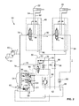
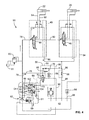
- FIGS. 2-4 show respective standby, working and stall operating modes associated with a fluid control system 50.
- Fluid control system 50 includes a variable displacement pump 52 having a load system control 54, with pump 52 being configured to operate in an open center mode.
- Fluid control system 50 further includes a pump control 56 having a first arrangement 58 and a second arrangement 60 as will be discussed in further detail below.
- fluid rams 22, 26 may be associated with a working machine 10 such as a backhoe or backhoe loader. Fluid rams 22, 26 are controlled by respective operator control valves 44, 46, with control valve 44 being contained within operator control valve assembly 45.
- fluid control system 50 is operating in a standby mode.
- a first load sensor pressure is generated by pump 52 inside of a line 78 that bifurcates and is provided to pump control 56 and operator control valve 44 of operator control valve assembly 45.
- first load sensor pressure flowing inside of line 78 flows through operator control valve 44 of operator control valve assembly 45, to line 92, which then flows through operator control valve 46, to line 94 which encounters a first flow restriction device 64.
- first flow restriction device 64 is configured to permit fluid flow therethrough at a pressure greater than a pressure required to flow through a second flow restriction device 66, the pressure required to flow through the second floor restriction device 66 similarly being greater than a pressure required to flow through a third flow restriction device 68 associated with pump control 56.
- first load sensor pressure contained inside line 94 is configured to flow through the first flow restriction device 64, and then to line 96 which is in fluid communication with reservoir 62.
- an actuator return pressure contained inside of line 86 is low.
- the actuator return pressure which is associated with the return pressure of respective actuators 22, 26 that are inactive during standby mode, is less than a pressure magnitude required to overcome either second flow restriction device 66 or to actuate pump control valve 70 away from a second position 74.
- first load sensor pressure contained in line 78 is blocked by pump control valve 70. Consequently, the magnitude of pump control pressure contained in line 88 and in fluid communication with load system control 54 and to a reservoir 62 via line 90, is insufficient to overcome the position of control valve 102 associated with load system control 54.
- first load sensor pressure contained in line 98 which is substantially the same pressure as the first load sensor pressure contained in line 78, is insufficient to overcome the position of control valve 104 associated with load system control 54.
- First load sensor pressure contained in line 98 flows through the control valves 102, 104 associated with load system control 54 and into line 99, actuating a control piston 100 associated with pump 52.
- the spring in the control piston would extend, resulting in the pump operating in a minimized displacement condition, i.e., the pump being destroked.
- FIG. 3 shows a working mode for fluid control system 50, in which, for example, an operator calls for pressurized fluid to actuator 22 by activating the spool position associated with operator control valve 44.
- first load sensor pressure contained in line 78 as generated by pump 52 passes through operator control valve 44 of operator control valve assembly 45, then through line 82 to provide the pressurized fluid to actuator 22 in order to actuate the associated fluid-operated attachment.
- the return pressure from actuator 22 contained in line 84 enters operator control valve assembly member 45, and exits operator control valve assembly 45 at line 86, and is identified as actuator return pressure.
- the actuator return pressure contained in line 86 passes through an optional first flow direction control device 76 and is regulated in parallel by a third flow restriction device 68 that is in fluid communication with reservoir 62 via line 90.
- the magnitude of the actuator return pressure is sufficient to actuate pump control valve 70 from second position 74 ( FIG. 2 ) to first position 72, permitting first load sensor pressure contained in line 78 to pass through pump control valve 70.
- the pump control pressure contained in line 88 is substantially the same pressure as the first load sensor pressure contained in line 78. As further shown in FIG.
- first load sensor pressure contained in line 98 which is substantially the same pressure as first load sensor pressure as contained in line 78, is insufficient to overcome the positions of the spools of control valves 102, 104 associated with load system control 54, with the first load sensor pressure being blocked by the spools of control valves 102, 104 of load system control 54 from reaching line 99 that is in fluid communication with control piston 100, pressurized fluid associated with reducing the operational displacement of pump 52 to be vented to reservoir 61. Stated another way, the displacement of pump 52 is permitted to be stroked, or urged toward an increased displacement pumping position.
- FIG. 4 shows a stall mode for fluid control system 50, in which, for example, an operator calls for pressurized fluid to actuator 22 by activating the spool position associated with operator control valve 44.
- first load sensor pressure contained in line 78 as generated by pump 52 which corresponds to a maximum pump pressure, passes through operator control valve 44 of operator control valve assembly 45, then through line 82 to provide the pressurized fluid to actuator 22 in order to attempt to actuate the associated fluid-operated attachment.
- the return pressure from actuator 22 contained in line 84 enters operator control valve assembly member 45, and exits operator control valve assembly 45 at line 86, and is identified as actuator return pressure.
- the actuator return pressure contained in line 86 passes through an optional first flow direction control device 76 and is regulated in parallel by a third flow restriction device 68 that is in fluid communication with reservoir 62 via line 90.
- the magnitude of the actuator return pressure is sufficient to actuate pump control valve 70 from second position 74 ( FIG. 2 ) to first position 72, permitting first load sensor pressure contained in line 78 to pass through pump control valve 70.
- the pump control pressure contained in line 88 is substantially the same pressure as the first load sensor pressure contained in line 78. As further shown in FIG.
- first load sensor pressure which in a stall mode is at maximum pump pressure, is contained in line 98 and flows through control valve 104 of load system control 54, and is in fluid communication with line 99 that is in fluid communication with control piston 100. Additionally, the spool of control valve 104 is also in fluid communication with line 101, permitting pressurized fluid associated with controlling the pressure output of pump 52 to be vented to reservoir 61. Since the pressure levels of the first load sensor pressure and control piston 100 are substantially equal in stall mode, the pump must merely maintain the maximum pump output pressure. Stated another way, the displacement of pump 52 is permitted to be destroked, or urged toward a maximum pressure pumping position having a low displacement.
- a relief valve 80 is placed in fluid communication with line 78, such that in response to an overpressurization condition in line 78, relief valve 80 is actuated in order to vent overpressurized fluid to reservoir 81.
- pump control pressure provided via line 88 in combination with a direct pump line, similar to line 98, except with the addition of a flow restriction device, such as similar to third flow restriction device 68 in combination with a conventional load sensing relief valve, in order to control the stall condition of the pump.
- control valve priority for use with a plurality of control valves as is well known, may be incorporated into the system.
- control system of the present disclosure can be used with uni-directional auxiliary attachments 106, such as shown in FIG. 5 , in which uni-directional auxiliary attachments 106, such as a hammer, receives pressurized fluid from line 78 as previously discussed.
- the return pressure from uni-directional auxiliary attachments 106 is contained in line 108 and connected to pump control 56, also as previously discussed.
Landscapes
- Engineering & Computer Science (AREA)
- General Engineering & Computer Science (AREA)
- Mechanical Engineering (AREA)
- Mining & Mineral Resources (AREA)
- Civil Engineering (AREA)
- Structural Engineering (AREA)
- Physics & Mathematics (AREA)
- Fluid Mechanics (AREA)
- Fluid-Pressure Circuits (AREA)
- Operation Control Of Excavators (AREA)
- Control Of Fluid Gearings (AREA)
Abstract
Description
- The present invention relates generally to the field of work vehicles. It relates more particularly to work vehicles having a fluid control system for manipulating attachments.
- With a focus on fuel economy and increasing system pressures to achieve greater levels of machine performance, there is a trend for more hydraulic or fluid systems to utilize a variable displacement pump. The variable displacement pump is more efficient, and its abilities to "destroke", i.e., operating at reduced displacement and/or pressure levels, can reduce fuel consumption. In an attempt to maximize efficiency, most variable displacement pumps operate in a closed center mode, in which generally, the system provides maximum fluid pressure to the control valves of the system, irrespective of whether the valves are actuated or not. The pumps vary their flow rate, pumping significantly reduced amounts of pressurized fluid until an operator actuates a valve associated with a hydraulic actuator controlling an attachment, such as associated with operation of a work vehicle, for example, a backhoe or backhoe loader. A benefit of a closed center system is that a hydraulic pump is destroked at stall and also at standby conditions, only supplying a required flow of pressurized fluid upon demand, which reduces losses associated with system operation. However, operating in a closed center mode increases the complexity of the system, resulting in increased operating costs.
- Variable displacement pumps can also be used in an open center operating mode, in which the pump provides a continuous flow of pressurized fluid to the system. While systems utilizing a conventional open center operating mode are less complex and therefore less expensive to operate his compared to operating in a closed center mode, there are drawbacks associated with a conventional open center operating mode. For example, in a standby condition, the pump operates at a maximum displacement condition, resulting in lower operating efficiencies.
- Accordingly, it would be desirable to inexpensively operate a pump in an open center mode that would permit the pump to operate at a destroked or minimized displacement condition in response to the system operating in either a standby mode or a stall mode.
- The present invention relates to a fluid control system including a variable displacement pump having a load system control and configured to operate in an open center mode. A pump control is operable between a first arrangement and a second arrangement, the pump control receiving pressurized fluid from a first load sensor pressure in fluid communication with the pump and an actuator return pressure in fluid communication with an actuator configured to operate using pressurized fluid from the system. The pump control provides a selective pump control pressure to the pump load system control. When the system is operating in a standby mode, the pump control is urged to the first arrangement, the pump control pressure being insufficient to overcome the first load sensor pressure applied to the pump load system control, resulting in the pump operating in a first minimized displacement condition. When the system is in a stall mode, the pump control is urged to the second arrangement, the pump control pressure being sufficient to overcome the first load sensor pressure applied to the pump load system control, resulting in the pump operating in a second minimized displacement condition.
- The present invention further relates to a work machine including a variable displacement pump having a load system control and configured to operate in an open center mode. A pump control is operable between a first arrangement and a second arrangement, the pump control receiving pressurized fluid from a first load sensor pressure in fluid communication with the pump and an actuator return pressure in fluid communication with an actuator configured to operate using pressurized fluid from the system. The pump control provides a selective pump control pressure to the pump load system control. When the system is operating in a standby mode, the pump control is urged to the first arrangement, the pump control pressure being insufficient to overcome the first load sensor pressure applied to the pump load system control, resulting in the pump operating in a first minimized displacement condition. When the system is in a stall mode, the pump control is urged to the second arrangement, the pump control pressure being sufficient to overcome the first load sensor pressure applied to the pump load system control, resulting in the pump operating in a second minimized displacement condition.
- An advantage of the present invention is the capability to inexpensively operate a pump in an open center mode, in which the pump can operate in a destroke or minimized displacement condition while the system operates in either a standby mode or a stall mode.
- Other features and advantages of the present invention will be apparent from the following more detailed description of the preferred embodiment, taken in conjunction with the accompanying drawings which illustrate, by way of example, the principles of the invention.
-
-
FIG. 1 shows a top perspective view of an embodiment of a work machine of the present invention; and -
FIGS. 2-5 show schematics of a fluid control system of the present invention. - Wherever possible, the same reference numbers will be used throughout the drawings to refer to the same or like parts.
- Referring to the drawings for a description of an
earthworking machine 10 that employs the present invention,FIG. 1 shows aboom 14 in a lowered position.Boom 14 pivots about apivot joint 34 and coincident pivot axis of aframe 20 and is controlled by extension/contraction of an actuator orfluid ram 22 connected betweenpivot joints arm 16, often referred to as a dipper, pivots aboutpivot joint 32 ofboom 14 and is controlled by extension/contraction of an actuator orfluid ram 24 connected betweenpivot joints attachment 18, such as a bucket, is pivotably connected toarm 16 and is controlled by extension/contraction of an actuator orfluid ram 26 connected betweenpivot joint 40 and interconnectedlinkages 42. Abackhoe 12 comprises the combination ofboom 14,arm 16, implement 18 and pivoting connections therebetween. -
FIGS. 2-4 show respective standby, working and stall operating modes associated with afluid control system 50.Fluid control system 50 includes avariable displacement pump 52 having aload system control 54, withpump 52 being configured to operate in an open center mode.Fluid control system 50 further includes apump control 56 having afirst arrangement 58 and asecond arrangement 60 as will be discussed in further detail below. As shown in the exemplary embodiment offluid control system 50,fluid rams working machine 10 such as a backhoe or backhoe loader.Fluid rams operator control valves control valve 44 being contained within operatorcontrol valve assembly 45. - As further shown
FIG. 2 ,fluid control system 50 is operating in a standby mode. A first load sensor pressure is generated bypump 52 inside of aline 78 that bifurcates and is provided to pumpcontrol 56 andoperator control valve 44 of operatorcontrol valve assembly 45. In standby mode, first load sensor pressure flowing inside ofline 78 flows throughoperator control valve 44 of operatorcontrol valve assembly 45, toline 92, which then flows throughoperator control valve 46, toline 94 which encounters a firstflow restriction device 64. In one embodiment, firstflow restriction device 64 is configured to permit fluid flow therethrough at a pressure greater than a pressure required to flow through a secondflow restriction device 66, the pressure required to flow through the secondfloor restriction device 66 similarly being greater than a pressure required to flow through a thirdflow restriction device 68 associated withpump control 56. Upon encountering firstflow restriction device 64 in standby mode, the first load sensor pressure contained insideline 94 is configured to flow through the firstflow restriction device 64, and then toline 96 which is in fluid communication withreservoir 62. As further shown inFIG. 2 in standby mode, with the pressurized fluid being blocked byrespective control valves actuators line 86 is low. That is, the actuator return pressure, which is associated with the return pressure ofrespective actuators flow restriction device 66 or to actuatepump control valve 70 away from a second position 74. Withpump control valve 70 in second position 74, first load sensor pressure contained inline 78 is blocked bypump control valve 70. Consequently, the magnitude of pump control pressure contained inline 88 and in fluid communication withload system control 54 and to areservoir 62 vialine 90, is insufficient to overcome the position ofcontrol valve 102 associated withload system control 54. As a further result, first load sensor pressure contained inline 98, which is substantially the same pressure as the first load sensor pressure contained inline 78, is insufficient to overcome the position ofcontrol valve 104 associated withload system control 54. First load sensor pressure contained inline 98 flows through thecontrol valves load system control 54 and intoline 99, actuating acontrol piston 100 associated withpump 52. As a result, with the pressures associated withcontrol piston 100 ofpump 52 and the pump being substantially equal, the spring in the control piston would extend, resulting in the pump operating in a minimized displacement condition, i.e., the pump being destroked. -
FIG. 3 shows a working mode forfluid control system 50, in which, for example, an operator calls for pressurized fluid toactuator 22 by activating the spool position associated withoperator control valve 44. As a result, first load sensor pressure contained inline 78 as generated bypump 52 passes throughoperator control valve 44 of operatorcontrol valve assembly 45, then throughline 82 to provide the pressurized fluid toactuator 22 in order to actuate the associated fluid-operated attachment. The return pressure fromactuator 22 contained inline 84 enters operator controlvalve assembly member 45, and exits operatorcontrol valve assembly 45 atline 86, and is identified as actuator return pressure. The actuator return pressure contained inline 86 passes through an optional first flowdirection control device 76 and is regulated in parallel by a thirdflow restriction device 68 that is in fluid communication withreservoir 62 vialine 90. In working mode, the magnitude of the actuator return pressure is sufficient to actuatepump control valve 70 from second position 74 (FIG. 2 ) to first position 72, permitting first load sensor pressure contained inline 78 to pass throughpump control valve 70. As a result, the pump control pressure contained inline 88 is substantially the same pressure as the first load sensor pressure contained inline 78. As further shown inFIG. 3 in working mode, withpump control valve 70 in first position 72, the magnitude of pump control pressure contained inline 88 that is in fluid communication withload system control 54 is sufficient to overcomecontrol valve 102 associated withload system control 54 to move the spool ofcontrol valve 102 in aspool actuation direction 103. As a further result, first load sensor pressure contained inline 98, which is substantially the same pressure as first load sensor pressure as contained inline 78, is insufficient to overcome the positions of the spools ofcontrol valves load system control 54, with the first load sensor pressure being blocked by the spools ofcontrol valves load system control 54 from reachingline 99 that is in fluid communication withcontrol piston 100, pressurized fluid associated with reducing the operational displacement ofpump 52 to be vented toreservoir 61. Stated another way, the displacement ofpump 52 is permitted to be stroked, or urged toward an increased displacement pumping position. -
FIG. 4 shows a stall mode forfluid control system 50, in which, for example, an operator calls for pressurized fluid toactuator 22 by activating the spool position associated withoperator control valve 44. As a result, first load sensor pressure contained inline 78 as generated bypump 52, which corresponds to a maximum pump pressure, passes throughoperator control valve 44 of operatorcontrol valve assembly 45, then throughline 82 to provide the pressurized fluid toactuator 22 in order to attempt to actuate the associated fluid-operated attachment. The return pressure fromactuator 22 contained inline 84 enters operator controlvalve assembly member 45, and exits operatorcontrol valve assembly 45 atline 86, and is identified as actuator return pressure. The actuator return pressure contained inline 86 passes through an optional first flowdirection control device 76 and is regulated in parallel by a thirdflow restriction device 68 that is in fluid communication withreservoir 62 vialine 90. In stall mode, the magnitude of the actuator return pressure is sufficient to actuatepump control valve 70 from second position 74 (FIG. 2 ) to first position 72, permitting first load sensor pressure contained inline 78 to pass throughpump control valve 70. As a result, the pump control pressure contained inline 88 is substantially the same pressure as the first load sensor pressure contained inline 78. As further shown inFIG. 4 in stall mode, withpump control valve 70 in first position 72, the magnitude of pump control pressure contained inline 88 that is in fluid communication withload system control 54 is sufficient to overcome the position ofcontrol valve 102 associated withload system control 54. That is, the spool ofcontrol valve 102 is actuated inspool actuation direction 103. As a further result, first load sensor pressure contained inline 98, which is substantially the same pressure as first load sensor pressure as contained inline 78 andload system control 54 is sufficient to overcome the position ofcontrol valve 104 associated withload system control 54. That is, the spool ofcontrol valve 104 is actuated inspool actuation direction 105. As a further result, first load sensor pressure, which in a stall mode is at maximum pump pressure, is contained inline 98 and flows throughcontrol valve 104 ofload system control 54, and is in fluid communication withline 99 that is in fluid communication withcontrol piston 100. Additionally, the spool ofcontrol valve 104 is also in fluid communication withline 101, permitting pressurized fluid associated with controlling the pressure output ofpump 52 to be vented toreservoir 61. Since the pressure levels of the first load sensor pressure andcontrol piston 100 are substantially equal in stall mode, the pump must merely maintain the maximum pump output pressure. Stated another way, the displacement ofpump 52 is permitted to be destroked, or urged toward a maximum pressure pumping position having a low displacement. - It is to be understood that even when a pump is fully destroked, the pump still delivers a minimum flow of pressurized fluid. In the event that the demand for pressurized fluid is less than the minimum flow of the pump, the magnitude of fluid pressure would continue to increase. To prevent overpressurization of fluid in the system, a
relief valve 80 is placed in fluid communication withline 78, such that in response to an overpressurization condition inline 78,relief valve 80 is actuated in order to vent overpressurized fluid toreservoir 81. - In an alternate arrangement of the stall mode, in place of
control valves load system control 54 ofpump 52, pump control pressure provided vialine 88 in combination with a direct pump line, similar toline 98, except with the addition of a flow restriction device, such as similar to thirdflow restriction device 68 in combination with a conventional load sensing relief valve, in order to control the stall condition of the pump. - In addition, power beyond capability, providing control valve priority for use with a plurality of control valves as is well known, may be incorporated into the system.
- It is to be understood that the control system of the present disclosure can be used with uni-directional
auxiliary attachments 106, such as shown inFIG. 5 , in which uni-directionalauxiliary attachments 106, such as a hammer, receives pressurized fluid fromline 78 as previously discussed. The return pressure from uni-directionalauxiliary attachments 106 is contained in line 108 and connected to pumpcontrol 56, also as previously discussed. - While the invention has been described with reference to a preferred embodiment, it will be understood by those skilled in the art that various changes may be made and equivalents may be substituted for elements thereof without departing from the scope of the invention. In addition, many modifications may be made to adapt a particular situation or material to the teachings of the invention without departing from the essential scope thereof. Therefore, it is intended that the invention not be limited to the particular embodiment disclosed as the best mode contemplated for carrying out this invention, but that the invention will include all embodiments falling within the scope of the appended claims.
Claims (11)
- A fluid control system (50) comprising:- a variable displacement pump (52) having a load system control (54) and configured to operate in an open center mode; andcharacterized in that system (50) further comprising:- a pump control (56) operable between a first arrangement (58) and a second arrangement (60), the pump control (56) receiving pressurized fluid from a first load sensor pressure in fluid communication with the pump (52) and an actuator return pressure in fluid communication with an actuator (22, 26) configured to operate using pressurized fluid from the system (50), the pump control (56) providing a selective pump control pressure to the pump load system control (54);- wherein when the system (50) is operating in a standby mode, the pump control (56) is urged to the first arrangement (58), the pump control pressure being insufficient to overcome the first load sensor pressure applied to the pump load system control (54), resulting in the pump (52) operating in a first minimized displacement condition;- wherein when the system (50) is in a stall mode, the pump control (56) is urged to the second arrangement (60), the pump control pressure being sufficient to overcome the first load sensor pressure applied to the pump load system control (54), resulting in the pump (52) operating in a second minimized displacement condition.
- The system (50) according to claim 1, wherein in the standby mode, the pump control pressure is vented to a reservoir (62).
- The system (50) according to claim 1 or 2, wherein the system (50) includes a first flow restriction device (64) in communication with the first load sensor pressure in standby mode, the first flow restriction device (64) configured to permit a predetermined flow rate in the standby mode and corresponding to the first minimized displacement condition of the pump (52).
- The system (50) according to any of the preceding claims, wherein in the stall mode, the actuator return pressure urges the pump (52) control to the second arrangement (60).
- The system (50) according to claim 3, wherein the system (50) includes a second flow restriction device (66) in fluid communication with the second load sensor pressure, the second flow restriction device (66) permitting fluid flow at a pressure less than the first flow restriction device (64).
- The system (50) according to claim 5, wherein the pump control (56) includes a third flow restriction device (68) and a pump control valve (70).
- The system (50) according to claim 6, wherein the pump control valve (70) is configured to operate between a first position (72) in response to the pump control (56) operating in the first arrangement (58), and a second position (74) in response to the pump control (56) operating in the second arrangement (60).
- The system (50) according to claim 7, wherein when the pump control (56) operates in the second arrangement (60), the pump control valve (70) is in fluid communication with the second load sensor pressure.
- The system (50) according to any of the preceding claims, wherein the pump control (56) includes a first flow direction control device (76).
- The system (50) according to any of the preceding claims, wherein a relief valve (80) is in fluid communication with the pump (52) to prevent overpressurization of fluid in the system (50).
- A work machine (10) comprising a fluid control system (50) according to any of the preceding claims.
Applications Claiming Priority (1)
| Application Number | Priority Date | Filing Date | Title |
|---|---|---|---|
| US13/487,622 US9347200B2 (en) | 2012-06-04 | 2012-06-04 | Fluid control system for work vehicle |
Publications (3)
| Publication Number | Publication Date |
|---|---|
| EP2672022A2 true EP2672022A2 (en) | 2013-12-11 |
| EP2672022A3 EP2672022A3 (en) | 2017-06-07 |
| EP2672022B1 EP2672022B1 (en) | 2018-12-26 |
Family
ID=48613408
Family Applications (1)
| Application Number | Title | Priority Date | Filing Date |
|---|---|---|---|
| EP13169925.8A Active EP2672022B1 (en) | 2012-06-04 | 2013-05-30 | Hydarulic fluid control system for a work vehicle |
Country Status (3)
| Country | Link |
|---|---|
| US (1) | US9347200B2 (en) |
| EP (1) | EP2672022B1 (en) |
| BR (1) | BR102013013808B1 (en) |
Cited By (1)
| Publication number | Priority date | Publication date | Assignee | Title |
|---|---|---|---|---|
| EP3101180A1 (en) * | 2015-06-05 | 2016-12-07 | CNH Industrial Italia S.p.A. | Hydraulic actuation system for work machine |
Families Citing this family (4)
| Publication number | Priority date | Publication date | Assignee | Title |
|---|---|---|---|---|
| WO2014100594A1 (en) * | 2012-12-21 | 2014-06-26 | Eaton Corporation | Proportional flow control of a fluid pump assembly |
| CN104554432B (en) * | 2014-05-29 | 2017-04-12 | 四川大学 | Engineering machine steer-by-wire system |
| US10913435B2 (en) * | 2018-09-28 | 2021-02-09 | Goodrich Corporation | Hydraulic braking system and method |
| US11674534B2 (en) * | 2020-04-17 | 2023-06-13 | Oshkosh Corporation | Refuse vehicle control systems and methods |
Family Cites Families (14)
| Publication number | Priority date | Publication date | Assignee | Title |
|---|---|---|---|---|
| US3726089A (en) | 1971-04-08 | 1973-04-10 | Dowty Technical Dev Ltd | Fluid-pressure-operable systems |
| US3788077A (en) | 1972-07-13 | 1974-01-29 | Borg Warner | Open center control of variable pumps |
| US3809501A (en) | 1973-01-08 | 1974-05-07 | Gen Signal Corp | Hydraulic load sensitive system |
| US3952509A (en) | 1975-04-10 | 1976-04-27 | Allis-Chalmers Corporation | Hydraulic system combining open center and closed center hydraulic circuits |
| US4383412A (en) | 1979-10-17 | 1983-05-17 | Cross Manufacturing, Inc. | Multiple pump load sensing system |
| US4335577A (en) | 1980-06-19 | 1982-06-22 | Deere & Company | Hydraulic system having variable displacement pumps controlled by power beyond flow |
| US4479349A (en) | 1981-11-19 | 1984-10-30 | General Signal Corporation | Hydraulic control system |
| DE3914904C2 (en) * | 1989-05-05 | 1995-06-29 | Rexroth Mannesmann Gmbh | Regulation for a variable displacement pump that works depending on the load |
| EP0564939B1 (en) * | 1992-04-04 | 1995-12-13 | Mannesmann Rexroth AG | Hydraulic control system for several motors |
| JPH11303759A (en) * | 1998-04-21 | 1999-11-02 | Hitachi Constr Mach Co Ltd | Hydraulic pump regulator |
| JP4291759B2 (en) * | 2004-08-26 | 2009-07-08 | キャタピラージャパン株式会社 | Fluid pressure drive circuit |
| US20090025380A1 (en) | 2007-07-24 | 2009-01-29 | Parker Hannifin Corporation, An Ohio Corporation | Fixed/variable hybrid system |
| US7874151B2 (en) | 2008-03-17 | 2011-01-25 | Caterpillar Inc | Dual mode hydraulic circuit control and method |
| JP5391040B2 (en) * | 2009-11-26 | 2014-01-15 | キャタピラー エス エー アール エル | Swing hydraulic control device for work machine |
-
2012
- 2012-06-04 US US13/487,622 patent/US9347200B2/en not_active Expired - Fee Related
-
2013
- 2013-05-30 EP EP13169925.8A patent/EP2672022B1/en active Active
- 2013-06-04 BR BR102013013808-8A patent/BR102013013808B1/en not_active IP Right Cessation
Non-Patent Citations (1)
| Title |
|---|
| None |
Cited By (1)
| Publication number | Priority date | Publication date | Assignee | Title |
|---|---|---|---|---|
| EP3101180A1 (en) * | 2015-06-05 | 2016-12-07 | CNH Industrial Italia S.p.A. | Hydraulic actuation system for work machine |
Also Published As
| Publication number | Publication date |
|---|---|
| EP2672022A3 (en) | 2017-06-07 |
| BR102013013808A2 (en) | 2015-10-13 |
| US20130318957A1 (en) | 2013-12-05 |
| BR102013013808A8 (en) | 2017-10-03 |
| US9347200B2 (en) | 2016-05-24 |
| BR102013013808B1 (en) | 2021-09-08 |
| EP2672022B1 (en) | 2018-12-26 |
Similar Documents
| Publication | Publication Date | Title |
|---|---|---|
| EP2215310B1 (en) | Load sensing system, working machine comprising the system, and method for controlling a hydraulic function | |
| JP4870366B2 (en) | Closed circuit energy recovery system for work implements | |
| EP2679735B1 (en) | Construction machine with working attachment | |
| EP3301229B1 (en) | Hydraulic driving device of work machine | |
| US9890801B2 (en) | Hydraulic drive system for construction machine | |
| KR102733398B1 (en) | Contorl system for construction machinery and control method for construction machinery | |
| EP2672022B1 (en) | Hydarulic fluid control system for a work vehicle | |
| US8944103B2 (en) | Meterless hydraulic system having displacement control valve | |
| CN106321537B (en) | Hydraulic control system and corresponding mobile working device | |
| JP6450487B1 (en) | Hydraulic excavator drive system | |
| EP3311034B1 (en) | Load sensing hydraulic system for a working machine | |
| JP6685783B2 (en) | Excavator | |
| JP2018084196A (en) | Hydraulic drive system | |
| US10330128B2 (en) | Hydraulic control system for work machine | |
| US10889964B2 (en) | Drive system for construction machine | |
| CN107217694B (en) | Excavator | |
| US6612109B2 (en) | Hydraulic power boost system for a work vehicle | |
| US12371873B2 (en) | Work machine | |
| JP2018145984A (en) | Hydraulic transmission for construction machine | |
| US8763388B2 (en) | Hydraulic system having a backpressure control valve | |
| KR20160148020A (en) | Low noise control algorithm for hydraulic systems | |
| KR20130128850A (en) | Hydraulic systems of forklift | |
| JP6924161B2 (en) | Hydraulic system for construction machinery | |
| JP4933299B2 (en) | Hydraulic control equipment for construction machinery | |
| US8905077B2 (en) | Hydraulic main valve and auxiliary valve |
Legal Events
| Date | Code | Title | Description |
|---|---|---|---|
| PUAI | Public reference made under article 153(3) epc to a published international application that has entered the european phase |
Free format text: ORIGINAL CODE: 0009012 |
|
| AK | Designated contracting states |
Kind code of ref document: A2 Designated state(s): AL AT BE BG CH CY CZ DE DK EE ES FI FR GB GR HR HU IE IS IT LI LT LU LV MC MK MT NL NO PL PT RO RS SE SI SK SM TR |
|
| AX | Request for extension of the european patent |
Extension state: BA ME |
|
| RAP1 | Party data changed (applicant data changed or rights of an application transferred) |
Owner name: CNH INDUSTRIAL ITALIA S.P.A. |
|
| AK | Designated contracting states |
Kind code of ref document: A3 Designated state(s): AL AT BE BG CH CY CZ DE DK EE ES FI FR GB GR HR HU IE IS IT LI LT LU LV MC MK MT NL NO PL PT RO RS SE SI SK SM TR |
|
| AX | Request for extension of the european patent |
Extension state: BA ME |
|
| RIC1 | Information provided on ipc code assigned before grant |
Ipc: F04B 49/00 20060101ALI20170502BHEP Ipc: F15B 13/04 20060101ALI20170502BHEP Ipc: E02F 3/96 20060101AFI20170502BHEP Ipc: E02F 9/22 20060101ALI20170502BHEP |
|
| PUAL | Search report despatched |
Free format text: ORIGINAL CODE: 0009013 |
|
| STAA | Information on the status of an ep patent application or granted ep patent |
Free format text: STATUS: REQUEST FOR EXAMINATION WAS MADE |
|
| 17P | Request for examination filed |
Effective date: 20171207 |
|
| RBV | Designated contracting states (corrected) |
Designated state(s): AL AT BE BG CH CY CZ DE DK EE ES FI FR GB GR HR HU IE IS IT LI LT LU LV MC MK MT NL NO PL PT RO RS SE SI SK SM TR |
|
| GRAP | Despatch of communication of intention to grant a patent |
Free format text: ORIGINAL CODE: EPIDOSNIGR1 |
|
| STAA | Information on the status of an ep patent application or granted ep patent |
Free format text: STATUS: GRANT OF PATENT IS INTENDED |
|
| INTG | Intention to grant announced |
Effective date: 20180720 |
|
| RIC1 | Information provided on ipc code assigned before grant |
Ipc: F15B 13/04 20060101ALI20180706BHEP Ipc: F04B 49/00 20060101ALI20180706BHEP Ipc: E02F 9/22 20060101ALI20180706BHEP Ipc: F04B 49/12 20060101ALI20180706BHEP Ipc: E02F 3/96 20060101AFI20180706BHEP Ipc: F04B 49/08 20060101ALI20180706BHEP |
|
| GRAS | Grant fee paid |
Free format text: ORIGINAL CODE: EPIDOSNIGR3 |
|
| GRAA | (expected) grant |
Free format text: ORIGINAL CODE: 0009210 |
|
| STAA | Information on the status of an ep patent application or granted ep patent |
Free format text: STATUS: THE PATENT HAS BEEN GRANTED |
|
| AK | Designated contracting states |
Kind code of ref document: B1 Designated state(s): AL AT BE BG CH CY CZ DE DK EE ES FI FR GB GR HR HU IE IS IT LI LT LU LV MC MK MT NL NO PL PT RO RS SE SI SK SM TR |
|
| REG | Reference to a national code |
Ref country code: GB Ref legal event code: FG4D |
|
| REG | Reference to a national code |
Ref country code: CH Ref legal event code: EP |
|
| REG | Reference to a national code |
Ref country code: AT Ref legal event code: REF Ref document number: 1081592 Country of ref document: AT Kind code of ref document: T Effective date: 20190115 |
|
| REG | Reference to a national code |
Ref country code: DE Ref legal event code: R096 Ref document number: 602013048666 Country of ref document: DE |
|
| REG | Reference to a national code |
Ref country code: IE Ref legal event code: FG4D |
|
| PG25 | Lapsed in a contracting state [announced via postgrant information from national office to epo] |
Ref country code: LT Free format text: LAPSE BECAUSE OF FAILURE TO SUBMIT A TRANSLATION OF THE DESCRIPTION OR TO PAY THE FEE WITHIN THE PRESCRIBED TIME-LIMIT Effective date: 20181226 Ref country code: NO Free format text: LAPSE BECAUSE OF FAILURE TO SUBMIT A TRANSLATION OF THE DESCRIPTION OR TO PAY THE FEE WITHIN THE PRESCRIBED TIME-LIMIT Effective date: 20190326 Ref country code: HR Free format text: LAPSE BECAUSE OF FAILURE TO SUBMIT A TRANSLATION OF THE DESCRIPTION OR TO PAY THE FEE WITHIN THE PRESCRIBED TIME-LIMIT Effective date: 20181226 Ref country code: BG Free format text: LAPSE BECAUSE OF FAILURE TO SUBMIT A TRANSLATION OF THE DESCRIPTION OR TO PAY THE FEE WITHIN THE PRESCRIBED TIME-LIMIT Effective date: 20190326 Ref country code: LV Free format text: LAPSE BECAUSE OF FAILURE TO SUBMIT A TRANSLATION OF THE DESCRIPTION OR TO PAY THE FEE WITHIN THE PRESCRIBED TIME-LIMIT Effective date: 20181226 Ref country code: FI Free format text: LAPSE BECAUSE OF FAILURE TO SUBMIT A TRANSLATION OF THE DESCRIPTION OR TO PAY THE FEE WITHIN THE PRESCRIBED TIME-LIMIT Effective date: 20181226 |
|
| REG | Reference to a national code |
Ref country code: NL Ref legal event code: MP Effective date: 20181226 |
|
| REG | Reference to a national code |
Ref country code: LT Ref legal event code: MG4D |
|
| PG25 | Lapsed in a contracting state [announced via postgrant information from national office to epo] |
Ref country code: GR Free format text: LAPSE BECAUSE OF FAILURE TO SUBMIT A TRANSLATION OF THE DESCRIPTION OR TO PAY THE FEE WITHIN THE PRESCRIBED TIME-LIMIT Effective date: 20190327 Ref country code: RS Free format text: LAPSE BECAUSE OF FAILURE TO SUBMIT A TRANSLATION OF THE DESCRIPTION OR TO PAY THE FEE WITHIN THE PRESCRIBED TIME-LIMIT Effective date: 20181226 Ref country code: SE Free format text: LAPSE BECAUSE OF FAILURE TO SUBMIT A TRANSLATION OF THE DESCRIPTION OR TO PAY THE FEE WITHIN THE PRESCRIBED TIME-LIMIT Effective date: 20181226 Ref country code: AL Free format text: LAPSE BECAUSE OF FAILURE TO SUBMIT A TRANSLATION OF THE DESCRIPTION OR TO PAY THE FEE WITHIN THE PRESCRIBED TIME-LIMIT Effective date: 20181226 |
|
| REG | Reference to a national code |
Ref country code: AT Ref legal event code: MK05 Ref document number: 1081592 Country of ref document: AT Kind code of ref document: T Effective date: 20181226 |
|
| PG25 | Lapsed in a contracting state [announced via postgrant information from national office to epo] |
Ref country code: NL Free format text: LAPSE BECAUSE OF FAILURE TO SUBMIT A TRANSLATION OF THE DESCRIPTION OR TO PAY THE FEE WITHIN THE PRESCRIBED TIME-LIMIT Effective date: 20181226 |
|
| PG25 | Lapsed in a contracting state [announced via postgrant information from national office to epo] |
Ref country code: PL Free format text: LAPSE BECAUSE OF FAILURE TO SUBMIT A TRANSLATION OF THE DESCRIPTION OR TO PAY THE FEE WITHIN THE PRESCRIBED TIME-LIMIT Effective date: 20181226 Ref country code: PT Free format text: LAPSE BECAUSE OF FAILURE TO SUBMIT A TRANSLATION OF THE DESCRIPTION OR TO PAY THE FEE WITHIN THE PRESCRIBED TIME-LIMIT Effective date: 20190426 Ref country code: CZ Free format text: LAPSE BECAUSE OF FAILURE TO SUBMIT A TRANSLATION OF THE DESCRIPTION OR TO PAY THE FEE WITHIN THE PRESCRIBED TIME-LIMIT Effective date: 20181226 Ref country code: ES Free format text: LAPSE BECAUSE OF FAILURE TO SUBMIT A TRANSLATION OF THE DESCRIPTION OR TO PAY THE FEE WITHIN THE PRESCRIBED TIME-LIMIT Effective date: 20181226 |
|
| PG25 | Lapsed in a contracting state [announced via postgrant information from national office to epo] |
Ref country code: SM Free format text: LAPSE BECAUSE OF FAILURE TO SUBMIT A TRANSLATION OF THE DESCRIPTION OR TO PAY THE FEE WITHIN THE PRESCRIBED TIME-LIMIT Effective date: 20181226 Ref country code: EE Free format text: LAPSE BECAUSE OF FAILURE TO SUBMIT A TRANSLATION OF THE DESCRIPTION OR TO PAY THE FEE WITHIN THE PRESCRIBED TIME-LIMIT Effective date: 20181226 Ref country code: SK Free format text: LAPSE BECAUSE OF FAILURE TO SUBMIT A TRANSLATION OF THE DESCRIPTION OR TO PAY THE FEE WITHIN THE PRESCRIBED TIME-LIMIT Effective date: 20181226 Ref country code: IS Free format text: LAPSE BECAUSE OF FAILURE TO SUBMIT A TRANSLATION OF THE DESCRIPTION OR TO PAY THE FEE WITHIN THE PRESCRIBED TIME-LIMIT Effective date: 20190426 Ref country code: RO Free format text: LAPSE BECAUSE OF FAILURE TO SUBMIT A TRANSLATION OF THE DESCRIPTION OR TO PAY THE FEE WITHIN THE PRESCRIBED TIME-LIMIT Effective date: 20181226 |
|
| REG | Reference to a national code |
Ref country code: DE Ref legal event code: R097 Ref document number: 602013048666 Country of ref document: DE |
|
| PG25 | Lapsed in a contracting state [announced via postgrant information from national office to epo] |
Ref country code: DK Free format text: LAPSE BECAUSE OF FAILURE TO SUBMIT A TRANSLATION OF THE DESCRIPTION OR TO PAY THE FEE WITHIN THE PRESCRIBED TIME-LIMIT Effective date: 20181226 Ref country code: AT Free format text: LAPSE BECAUSE OF FAILURE TO SUBMIT A TRANSLATION OF THE DESCRIPTION OR TO PAY THE FEE WITHIN THE PRESCRIBED TIME-LIMIT Effective date: 20181226 |
|
| PLBE | No opposition filed within time limit |
Free format text: ORIGINAL CODE: 0009261 |
|
| STAA | Information on the status of an ep patent application or granted ep patent |
Free format text: STATUS: NO OPPOSITION FILED WITHIN TIME LIMIT |
|
| 26N | No opposition filed |
Effective date: 20190927 |
|
| REG | Reference to a national code |
Ref country code: CH Ref legal event code: PL |
|
| PG25 | Lapsed in a contracting state [announced via postgrant information from national office to epo] |
Ref country code: CH Free format text: LAPSE BECAUSE OF NON-PAYMENT OF DUE FEES Effective date: 20190531 Ref country code: MC Free format text: LAPSE BECAUSE OF FAILURE TO SUBMIT A TRANSLATION OF THE DESCRIPTION OR TO PAY THE FEE WITHIN THE PRESCRIBED TIME-LIMIT Effective date: 20181226 Ref country code: LI Free format text: LAPSE BECAUSE OF NON-PAYMENT OF DUE FEES Effective date: 20190531 |
|
| REG | Reference to a national code |
Ref country code: BE Ref legal event code: MM Effective date: 20190531 |
|
| PG25 | Lapsed in a contracting state [announced via postgrant information from national office to epo] |
Ref country code: SI Free format text: LAPSE BECAUSE OF FAILURE TO SUBMIT A TRANSLATION OF THE DESCRIPTION OR TO PAY THE FEE WITHIN THE PRESCRIBED TIME-LIMIT Effective date: 20181226 Ref country code: LU Free format text: LAPSE BECAUSE OF NON-PAYMENT OF DUE FEES Effective date: 20190530 |
|
| PG25 | Lapsed in a contracting state [announced via postgrant information from national office to epo] |
Ref country code: TR Free format text: LAPSE BECAUSE OF FAILURE TO SUBMIT A TRANSLATION OF THE DESCRIPTION OR TO PAY THE FEE WITHIN THE PRESCRIBED TIME-LIMIT Effective date: 20181226 |
|
| PG25 | Lapsed in a contracting state [announced via postgrant information from national office to epo] |
Ref country code: IE Free format text: LAPSE BECAUSE OF NON-PAYMENT OF DUE FEES Effective date: 20190530 |
|
| PG25 | Lapsed in a contracting state [announced via postgrant information from national office to epo] |
Ref country code: BE Free format text: LAPSE BECAUSE OF NON-PAYMENT OF DUE FEES Effective date: 20190531 |
|
| PG25 | Lapsed in a contracting state [announced via postgrant information from national office to epo] |
Ref country code: CY Free format text: LAPSE BECAUSE OF FAILURE TO SUBMIT A TRANSLATION OF THE DESCRIPTION OR TO PAY THE FEE WITHIN THE PRESCRIBED TIME-LIMIT Effective date: 20181226 |
|
| REG | Reference to a national code |
Ref country code: DE Ref legal event code: R082 Ref document number: 602013048666 Country of ref document: DE Representative=s name: KROHER STROBEL RECHTS- UND PATENTANWAELTE PART, DE |
|
| PG25 | Lapsed in a contracting state [announced via postgrant information from national office to epo] |
Ref country code: MT Free format text: LAPSE BECAUSE OF FAILURE TO SUBMIT A TRANSLATION OF THE DESCRIPTION OR TO PAY THE FEE WITHIN THE PRESCRIBED TIME-LIMIT Effective date: 20181226 Ref country code: HU Free format text: LAPSE BECAUSE OF FAILURE TO SUBMIT A TRANSLATION OF THE DESCRIPTION OR TO PAY THE FEE WITHIN THE PRESCRIBED TIME-LIMIT; INVALID AB INITIO Effective date: 20130530 |
|
| PG25 | Lapsed in a contracting state [announced via postgrant information from national office to epo] |
Ref country code: MK Free format text: LAPSE BECAUSE OF FAILURE TO SUBMIT A TRANSLATION OF THE DESCRIPTION OR TO PAY THE FEE WITHIN THE PRESCRIBED TIME-LIMIT Effective date: 20181226 |
|
| PGFP | Annual fee paid to national office [announced via postgrant information from national office to epo] |
Ref country code: DE Payment date: 20250528 Year of fee payment: 13 |
|
| PGFP | Annual fee paid to national office [announced via postgrant information from national office to epo] |
Ref country code: GB Payment date: 20250520 Year of fee payment: 13 |
|
| PGFP | Annual fee paid to national office [announced via postgrant information from national office to epo] |
Ref country code: IT Payment date: 20250522 Year of fee payment: 13 |
|
| PGFP | Annual fee paid to national office [announced via postgrant information from national office to epo] |
Ref country code: FR Payment date: 20250526 Year of fee payment: 13 |