EP2672009B1 - Self-propelled construction machine, in particular road milling machine, recycler or stabiliser - Google Patents
Self-propelled construction machine, in particular road milling machine, recycler or stabiliser Download PDFInfo
- Publication number
- EP2672009B1 EP2672009B1 EP13183034.1A EP13183034A EP2672009B1 EP 2672009 B1 EP2672009 B1 EP 2672009B1 EP 13183034 A EP13183034 A EP 13183034A EP 2672009 B1 EP2672009 B1 EP 2672009B1
- Authority
- EP
- European Patent Office
- Prior art keywords
- drive
- road
- engine
- milling machine
- engines
- Prior art date
- Legal status (The legal status is an assumption and is not a legal conclusion. Google has not performed a legal analysis and makes no representation as to the accuracy of the status listed.)
- Active
Links
Images


Classifications
-
- E—FIXED CONSTRUCTIONS
- E01—CONSTRUCTION OF ROADS, RAILWAYS, OR BRIDGES
- E01C—CONSTRUCTION OF, OR SURFACES FOR, ROADS, SPORTS GROUNDS, OR THE LIKE; MACHINES OR AUXILIARY TOOLS FOR CONSTRUCTION OR REPAIR
- E01C21/00—Apparatus or processes for surface soil stabilisation for road building or like purposes, e.g. mixing local aggregate with binder
-
- E—FIXED CONSTRUCTIONS
- E01—CONSTRUCTION OF ROADS, RAILWAYS, OR BRIDGES
- E01C—CONSTRUCTION OF, OR SURFACES FOR, ROADS, SPORTS GROUNDS, OR THE LIKE; MACHINES OR AUXILIARY TOOLS FOR CONSTRUCTION OR REPAIR
- E01C23/00—Auxiliary devices or arrangements for constructing, repairing, reconditioning, or taking-up road or like surfaces
- E01C23/06—Devices or arrangements for working the finished surface; Devices for repairing or reconditioning the surface of damaged paving; Recycling in place or on the road
- E01C23/08—Devices or arrangements for working the finished surface; Devices for repairing or reconditioning the surface of damaged paving; Recycling in place or on the road for roughening or patterning; for removing the surface down to a predetermined depth high spots or material bonded to the surface, e.g. markings; for maintaining earth roads, clay courts or like surfaces by means of surface working tools, e.g. scarifiers, levelling blades
- E01C23/085—Devices or arrangements for working the finished surface; Devices for repairing or reconditioning the surface of damaged paving; Recycling in place or on the road for roughening or patterning; for removing the surface down to a predetermined depth high spots or material bonded to the surface, e.g. markings; for maintaining earth roads, clay courts or like surfaces by means of surface working tools, e.g. scarifiers, levelling blades using power-driven tools, e.g. vibratory tools
- E01C23/088—Rotary tools, e.g. milling drums
-
- B—PERFORMING OPERATIONS; TRANSPORTING
- B60—VEHICLES IN GENERAL
- B60K—ARRANGEMENT OR MOUNTING OF PROPULSION UNITS OR OF TRANSMISSIONS IN VEHICLES; ARRANGEMENT OR MOUNTING OF PLURAL DIVERSE PRIME-MOVERS IN VEHICLES; AUXILIARY DRIVES FOR VEHICLES; INSTRUMENTATION OR DASHBOARDS FOR VEHICLES; ARRANGEMENTS IN CONNECTION WITH COOLING, AIR INTAKE, GAS EXHAUST OR FUEL SUPPLY OF PROPULSION UNITS IN VEHICLES
- B60K25/00—Auxiliary drives
- B60K25/02—Auxiliary drives directly from an engine shaft
Definitions
- the invention relates to a self-propelled road milling machine, which has a working unit for carrying out necessary for the construction work.
- road construction self-propelled construction machines of different types are used. These include the well-known road milling machines, recyclers or stabilizers. With the known road milling machines existing road layers of the road superstructure can be removed and with the known recyclers existing road surfaces can be restored. The known stabilizers are used to prepare the substructure for road construction.
- Such self-propelled construction machines have a working unit, which is a work roll, in particular a milling drum equipped with milling cutters.
- the work roll is driven by a drive unit.
- a power transmission unit To transmit the drive power from the drive unit to the working unit is a power transmission unit.
- the DE 10 2005 017 754 A1 ( WO 2006/108757 A1 ) describes a self-propelled construction machine, in particular road milling machine, recycler or stabilizer.
- the drive unit of the known construction machine has an internal combustion engine, which drives the work roll via a traction mechanism, in particular a belt drive.
- the construction machine provides for a division of the drive train into two groups, one group containing the internal combustion engine, which is supported relatively softly on the machine frame, whereby the vibrations transmitted to the machine frame are strongly damped, and the other group containing the work roll, With high strength is mounted almost rigidly on the machine frame, whereby higher forces are supported and thus higher powers are transferable.
- the WO 2006/108757 A1 discloses the features of the introductory part of claim 1.
- Road milling machines with only one internal combustion engine are also from the WO 2004/005623 A1 and the EP 1 167 626 A1 known.
- the DE 10 2005 017 754 A1 indicates explicitly that in an effort to increase performance, the footprint of the drive motor increases, which must be accommodated within the fixed transport width of the construction machine. Exceeding the specified transport width would have the consequence that a transport of the construction machine would be possible only with a special permit. Due to this restriction, the available power of the drive unit of the construction machine is therefore limited.
- the EP 1 818 524 A1 describes as an agricultural vehicle a self-propelled forage harvester comprising a vehicle frame carried by a chassis having front wheels and rear wheels. In the working direction in front of the front wheels, a chopper drum with a chopper knife for crushing the crop is arranged. At the rear of the vehicle is located above the rear wheels, a drive unit comprising two transversely mounted drive motors, which can be operated at optimal operating points. In the EP 1 818 524 A1 there is the indication that the drive motors can be arranged in any motor vehicle executed arbitrarily.
- From the EP 1 640 201 A1 is a self-propelled harvester known, which has a main motor and a side engine.
- the coupling of the two motors is effected by a coupling which establishes the frictional connection between the auxiliary motor and a spur gear and thus between the main and auxiliary motor.
- the maximum width and the installation position of the drive unit are for the construction of a forage harvester as a agricultural and forestry machine in practice is not important or in a forage harvester play other structural considerations a role.
- the drive unit of the known forage harvester is located above the rear wheels in the rear region of the machine, which should be advantageous for the weight distribution.
- the invention is based on the object to provide a road milling machine of the type mentioned, without exceeding the fixed predetermined transport width a drive unit which has a higher performance compared to the known construction machines.
- the road milling machine according to the invention is characterized in that the drive unit has a first drive motor and a second drive motor, wherein the power transmission device is designed such that the drive power of the first and second drive motor can be transmitted simultaneously to the working unit.
- the drive unit may still have more drive motors, the drive power of all motors can be simultaneously transferred to the working unit. In practice, however, a drive unit with "only" a first and a second drive motor will be sufficient.
- the multi-motor drive unit still offers the following advantages.
- propulsion engines For the propulsion engines, commercially available relatively low power engines can be used, which are generally more cost effective than larger, higher power engines.
- the maintenance of the construction machine is not complicated by the use of another engine compared to construction machines low power because the construction machine according to the invention with two drive motors with respect to the individual drive motor requires the same maintenance or spare parts, such as a construction machine with lower power, which has only one of the drive motors.
- the working unit has a milling drum equipped with milling cutters.
- the first and second drive motor are at a distance from each other, as close as possible to each other lying or tightly arranged one above the other.
- the juxtaposed motors are arranged in a plane which lies above the plane in which the working unit is arranged on the machine frame. As a result, a particularly space-saving arrangement of the individual units is achieved at the given transport width.
- the superimposed motors can also be arranged in front of or behind the working unit in the direction of travel.
- the power transmission device for transmitting the drive power from the drive unit to the working unit, a first means for switching the torque of the first drive motor and a second means for switching the torque of the second drive motor, for example, a first and second clutch on.
- the first and second drive motors are arranged in the machine frame transversely to the direction of travel of the construction machine.
- Such an arrangement of the drive motors has the advantage that the power transmission unit for transmitting the power from the drive unit to the working unit whose drive shaft in the known road milling, recycling or Stabilisierem also transverse to the direction of travel may have a relatively simple structure.
- the drive unit of the road milling machine according to the invention allows an increase in power in the limited width of the machine, taking into account the predetermined arrangement of the individual units, without extensive, especially costly changes to the design of the construction machine would be required.
- the drive motors are preferably internal combustion engines, in particular diesel engines.
- both motors have the same power, so that a doubling of the power with simultaneous operation of both motors is possible.
- one of the two engines has a greater power than the other engine.
- the drive motors are preferably motors of the same design, even if they should differ in performance from each other. This simplifies the spare parts procurement and maintenance of the engines.
- the engines are the same engines that differ neither in design nor performance.
- the drive unit can drive other units of the road milling machine, which include, for example, units for height adjustment, the steering and the water pump. But these consumers require a much lower performance than the drive of the work roll. Preferably, these units are driven by hydraulic pumps.
- the device for driving the hydraulic pumps for the ancillaries is preferably coupled to the first drive motor, which is the main engine.
- the drive for the hydraulic pumps for the ancillaries on a pump distributor gearbox.
- the power transmission device has a traction mechanism, which is a belt transmission.
- the belt transmission has a first pulley, which is non-rotatably connected to a first driven by the first drive motor output shaft, and a second pulley, which is non-rotatably connected to a drivable by the second drive motor output shaft, and a third pulley, with one of the Working unit driving drive shaft is rotatably connected.
- At least one drive belt runs through the pulleys, whereby the drive shaft of the working unit is driven by the output shafts of the two motors.
- the multi-engine drive unit of the construction machine advantageously provides that the first and second output shafts are respectively coupled to the first and second drive motors via a first and second articulated coupling device.
- a first and second articulated coupling device In principle, however, it is also possible that only one of the two drive motors is coupled to the drive shaft via an articulated coupling device. This results in the advantage that the storage of the drive motor can be made considerably softer as the bearing of the remaining elements of the drive train, which should be attached as rigid as possible to the machine frame.
- the articulated coupling device can be rotationally rigid, for example a propeller shaft, or torsionally elastic, for example an elastomer coupling.
- the means for switching the torque of the first and second drive motor are preferably arranged between the drive motor and the first and second output shaft. Between the drive motor and the output shaft, the device for driving at least one hydraulic pump is preferably also arranged. It is in principle possible to arrange the means for driving the hydraulic pump between the drive motor and the clutch or the clutch between the drive motor and means for driving the hydraulic pumps.
- Internal combustion engines in general generally do not produce a uniform rotational movement.
- the rotation of the output are always superimposed on torsional vibrations.
- vibrations are introduced into the machine frame via the coupling devices.
- internal combustion engines in particular diesel engines of the newer generation, which are characterized by a lightweight construction, occur at changed ignition timing and injection timing to meet the applicable emission regulations, these vibrations increasingly. Due to material wear and fatigue, the torsional vibrations can lead to shorter service lives, for example, of the gearbox or clutches in the drive train. The other vibrations, unless they are absorbed by the elastic coupling device, reduce the comfort by z. B. emitted as sound.
- the crankshaft angle of the crankshaft of the first internal combustion engine with respect to the crankshaft angle of the crankshaft of the second internal combustion engine is so adjustable during operation of both internal combustion engines, that the torsional vibrations generated by both internal combustion engines in the common transmission of the drive power of the first and second Internal combustion engine on the working unit at least partially eliminate each other.
- the vibrations introduced into the machine frame can also be reduced as a result.
- Fig. 1 shows as an example of a self-propelled road milling machine, a so-called large milling machine for milling road surfaces made of asphalt, concrete or the like.
- the large milling machine has a supported by a chassis 1 machine frame 2 with a control station 2A.
- the chassis 1 of the milling machine includes, for example, four track drives 1A, 1B, which are arranged on the front and rear sides on both sides of the vehicle frame.
- the crawler tracks which allow forward and backward movement of the large milling machine along a lane, are height-adjustable mounted on lifting columns 3, which are mounted on the machine frame 2, so that the machine frame can be positioned in a desired position. It is understood that instead of crawler wheels and wheels can be provided.
- the road milling machine has a working unit, which is a milling device with a milling drum 4, which is equipped with milling tools 4A.
- the milling drum 4 is disposed on the machine frame 1 between the front and rear crawler tracks 1A, 1B. With the milling drum 4, the road surface is milled.
- the milling machine on a supported by the machine frame 2 drive unit 5, which in Fig. 1 shown in dashed lines.
- the drive unit 5 is arranged on the machine frame 1 between the front and rear track drive 1A, 1B in a plane which lies above the plane in which the milling drum 4 is located.
- the drive unit 5 drives in addition to the milling drum 4 and the chain drives 1A, 1B and other units of the milling machine, including, for example, the lifting columns 3 for the height adjustment of the machine frame 2 or not shown actuators for the steering or a water pump, not shown for cooling the milling tool 4A Count the milling drum 4.
- a power transmission device 6 To transmit the drive power from the drive unit 5 to the milling drum 4 is a power transmission device 6, the in Fig. 1 in dashed lines only hinted at.
- Fig. 2 shows that the milling cutter 4 equipped with milling drum is arranged transversely to the direction of travel in the machine frame 2.
- the milling drum 4 has a drive shaft 4B mounted on the machine frame 2, which extends transversely to the direction of travel.
- the drive shaft may also be mounted in a roll housing, which in turn is connected to the machine frame.
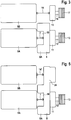
- the drive unit 5 for driving the milling drum 4 comprises a first and a second internal combustion engine 5A, 5B, in particular two diesel engines ( Fig. 3 . Fig. 4 ).
- both diesel engines are the same engines.
- the two diesel engines can also be motors of different design and / or performance.
- the first motor hereinafter referred to as the main motor 5A, is coupled via an articulated coupling device 7, for example a cardan shaft or elastomer coupling, to a pump distributor gearbox 8 (PVG) ( Fig. 3 ).
- a spur gear is arranged, which drives a plurality of hydraulic pumps 8A together, which are arranged distributed circumferentially ( Fig. 4 ).
- the arrangement of the hydraulic pumps 8A results in a central, free inner space 10 between the hydraulic pumps 8A, in which the coupling device 7 is located.
- a particularly space-saving arrangement of the components is achieved, so that in view of the predetermined transport width of the construction machine sufficient space for the transversely mounted engine is available.
- the pump distributor 8 is coupled via a device 11 for switching the torque, for example a clutch with a drive shaft 12, rotatably on a pulley 13 sits.
- the second motor hereinafter referred to as the auxiliary motor 5B, is arranged transversely to the direction of travel at a close distance from the main motor 5A (FIG. Fig. 3 ).
- the auxiliary motor 5B is coupled via a further articulated coupling device 14, for example a cardan shaft or elastomer coupling, to a second device 15 for switching the torque, for example a clutch, to which in turn a drive shaft 16 is coupled, on which a second belt pulley 17 is seated.
- the pump distributor 8 is not associated with the main motor 5A, but the sub motor 5B. It is also possible that not the pump distributor 8 directly to the main engine and the clutch 11 to the pump distributor gearbox, but the clutch 11 is coupled directly to the main engine and the pump distributor gearbox to the clutch. Then, the free space 10 of the pump distributor gear 8 instead of the coupling device 7, the clutch 11 record. In both cases results in a compact design.
- the hydraulic pumps 8A which are driven by the pump distributor 8, serve to drive additional units, but require a much lower power than the drive of the milling drum.
- the main and sub motors 5A, 5B are fixed to the machine frame 2 by means of elastic spring / damper means 21, which have a low spring rigidity, so that the vibrations occurring in particular in these motors are transmitted as little as possible to the machine frame.
- the remaining part of the drive train which includes the pump transfer case 8 of the main motor 5A, with spring / damping elements 23 attached to the machine frame 2, which have a high spring stiffness or rigid.
- an alternative embodiment with reference to the Fig. 2 . 5 and 6 described by the reference to the Fig. 2 . 3 and 4 described embodiment differs in that the addition of the benefits of the two motors 5A, 5B does not take place via a belt transmission, but a spur gear.
- the main motor 5A and the sub-motor 5B are connected to each other via a spur gear 21, which may be integrated into the pump transfer case 8 of the main motor 5A.
- spur gear 21 may be integrated into the pump transfer case 8 of the main motor 5A.
- the spur gear can have a clutch 15, which is integrated in the transmission unit.
- the coupling of the auxiliary motor 5A to the spur gear 21 is again via a coupling device 14 ', in particular propeller shaft or elastomer coupling.
- Fig. 6 shows that the drive belt 9 'on the main motor 5A associated pulley 13, the pulley 18 of the milling drum 4 and the tension roller 20' run, which is wrapped in this embodiment of the drive belt 9 'from the outside.
- a pulley may be provided on the output shaft of one motor and two pulleys on the output shaft of the other motor, with a first belt or belts running over the first pulley of the two pulleys of one engine and the pulley of the other engine.
- a second drive belt or belts may pass over the other of the two pulleys of the one motor and the pulley of the work roll. It is basically irrelevant whether one or the other engine is the main or auxiliary engine.
- This embodiment corresponds to the embodiment of Figures 5 and 6, wherein the two motors but not via the spur gear, but are coupled together via at least one other drive belt.
- the drive motors 5A, 5B of the drive unit of the construction machine according to the invention are preferably lightweight diesel engines in which, in principle, torsional vibrations can occur.
- crankshaft angle of the crankshaft of the first and second internal combustion engine 5A, 5B adjustable during operation of both internal combustion engines, so that the crankshaft of the first engine with respect to the crankshaft of the second motor by a selectable angle forward or can run after.
- the drive unit 4 has a control unit 19 for reducing the vibrations that occur in the FIGS. 4 and 5 is shown schematically.
- the control unit 19 is configured such that the crankshaft angle of the crankshaft, not shown, of the first internal combustion engine 5A with respect to the crankshaft angle of the crankshaft, not shown, of the second internal combustion engine 5B is set such that the torsional vibrations generated by both internal combustion engines in the common transmission of the drive power of First and second motor with the power transmission device 6 on the work unit 4 at least partially eliminate.
- the first motor 5A is operated so that its crankshaft protrudes by a certain angle
- the second motor 5B is operated so that its crankshaft lags by a certain angle.
- the attributable to the first and second motor torsional vibrations that are transmitted to the drive train are therefore shifted by a certain phase angle to each other.
- the control unit 19 adjusts the crankshaft angles such that the torsional vibrations superimposed in the drive train at least partially eliminate one another, ie vibrations with a specific amplitude in one direction compensate for vibrations of a similarly large amplitude in the opposite direction. The same applies to the other vibrations introduced in the machine frame.
Description
Die Erfindung betrifft eine selbstfahrende Straßenfräsmaschine, die über eine Arbeitseinheit zur Durchführung von für die Baumaßnahme erforderlichen Arbeiten verfügt.The invention relates to a self-propelled road milling machine, which has a working unit for carrying out necessary for the construction work.
Im Straßenbau werden selbstfahrende Baumaschinen unterschiedlicher Bauart eingesetzt. Zu diesen zählen die bekannten Straßenfräsmaschinen, Recycler oder Stabilisierer. Mit den bekannten Straßenfräsmaschinen können bestehende Straßenschichten des Straßenoberbaus abgetragen und mit den bekannten Recyclern bestehende Straßenbeläge wiederhergestellt werden. Die bekannten Stabilisierer dienen der Vorbereitung des Unterbaus für den Straßenbau.In road construction self-propelled construction machines of different types are used. These include the well-known road milling machines, recyclers or stabilizers. With the known road milling machines existing road layers of the road superstructure can be removed and with the known recyclers existing road surfaces can be restored. The known stabilizers are used to prepare the substructure for road construction.
Derartige selbstfahrende Baumaschinen verfügen über eine Arbeitseinheit, bei der es sich um eine Arbeitswalze, insbesondere eine mit Fräsmeißeln bestückte Fräswalze handelt.Such self-propelled construction machines have a working unit, which is a work roll, in particular a milling drum equipped with milling cutters.
Die Arbeitswalze wird von einer Antriebseinheit angetrieben. Zur Übertragung der Antriebsleistung von der Antriebseinheit auf die Arbeitseinheit dient eine Kraftübertragungseinheit.The work roll is driven by a drive unit. To transmit the drive power from the drive unit to the working unit is a power transmission unit.
Die
Straßenfräsmaschinen mit nur einem Verbrennungsmotor sind auch aus der
Die
Die
Aus der
Der Erfindung liegt die Aufgabe zu Grunde, eine Straßenfräsmaschine der eingangs genannten Art zu schaffen, die ohne Überschreitung der fest vorgegebenen Transportbreite eine Antriebseinheit aufweist, die über eine gegenüber den bekannten Baumaschinen höhere Leistung verfügt.The invention is based on the object to provide a road milling machine of the type mentioned, without exceeding the fixed predetermined transport width a drive unit which has a higher performance compared to the known construction machines.
Diese Aufgabe wird erfindungsgemäß mit den Merkmalen des Patentanspruchs 1 gelöst. Vorteilhafte Ausführungsformen der Erfindung sind Gegenstand der Unteransprüche.This object is achieved with the features of claim 1. Advantageous embodiments of the invention are the subject of the dependent claims.
Die erfindungsgemäße Straßenfräsmaschine zeichnet sich dadurch aus, dass die Antriebseinheit einen ersten Antriebsmotor und einen zweiten Antriebsmotor aufweist, wobei die Kraftübertragungseinrichtung derart ausgebildet ist, dass die Antriebsleistung des ersten und zweiten Antriebsmotors gleichzeitig auf die Arbeitseinheit übertragbar ist.The road milling machine according to the invention is characterized in that the drive unit has a first drive motor and a second drive motor, wherein the power transmission device is designed such that the drive power of the first and second drive motor can be transmitted simultaneously to the working unit.
Auch wenn in diesem Zusammenhang von einem ersten und einem zweiten Antriebsmotor die Rede ist, kann die Antriebseinheit noch über weitere Antriebsmotoren verfügen, wobei die Antriebsleistung sämtlicher Motoren gleichzeitig auf die Arbeitseinheit übertragbar ist. In der Praxis wird aber eine Antriebseinheit mit "nur" einem ersten und einem zweiten Antriebsmotor ausreichend sein.Even if in this context of a first and a second drive motor is mentioned, the drive unit may still have more drive motors, the drive power of all motors can be simultaneously transferred to the working unit. In practice, however, a drive unit with "only" a first and a second drive motor will be sufficient.
Im Hinblick auf die besonderen Anforderungen von selbstfahrenden Straßenfräsmaschinen und der sich aus den besonderen Anforderungen ergebenden Anordnung der einzelnen Aggregate der Baumaschine hat sich gezeigt, dass der Einsatz von zwei oder auch mehr als zwei Antriebsmotoren kleinerer Leistung anstelle eines Antriebsmotors mit einer größeren Leistung erhebliche Vorteile für die Baumaschine, insbesondere die Straßenfräse, den Recycler oder den Stabilisierer bietet.In view of the special requirements of self-propelled road milling machines and resulting from the special requirements arrangement of the individual units of the construction machine has been shown that the use of two or more than two drive motors of lower power instead of a drive motor with a larger power considerable advantages the construction machine, in particular the road milling machine, the recycler or the stabilizer offers.
Der Einsatz von zwei Antriebsmotoren kleinerer Leistung anstelle eines Motors größerer Leistung führt zu einem wesentlich kompakteren Aufbau der Antriebseinheit, der erst den Einsatz eines Antriebs mit einer gegenüber den bekannten Baumaschinen wesentlich höheren Leistung möglich macht. Bisher ist von Antriebseinheiten mit einer derart hohen Leistung bei Baumaschinen, insbesondere Straßenfräsen, Recyclern oder Stabilisierem, wegen der fest vorgegebenen Transportbreite der Maschine abgesehen worden. Eine Antriebseinheit mit einer höheren Leistung hätte eine Überschreitung der maximalen Transportbreite erforderlich gemacht, die eine Sondergenehmigung für den Transport der Baumaschine erfordert hätte.The use of two smaller power drive motors instead of a larger power motor leads to a much more compact design of the drive unit, which makes possible the use of a drive with a much higher performance compared to the known construction machines. So far, drive units with such a high performance in construction machines, especially road milling machines, recyclers or Stabilisierem, because of the fixed predetermined transport width of the machine have been omitted. A higher performance drive unit would have required exceeding the maximum transport width which would have required a special permit for the transport of the construction machine.
Neben der Erhöhung der Leistung bietet die mehrmotorige Antriebseinheit noch die folgenden Vorteile.In addition to increasing performance, the multi-motor drive unit still offers the following advantages.
Für die Antriebsmotoren können handelsübliche Motoren mit verhältnismäßig geringer Leistung eingesetzt werden, die im Allgemeinen gegenüber größeren Motoren mit höherer Leistung kostengünstiger sind.For the propulsion engines, commercially available relatively low power engines can be used, which are generally more cost effective than larger, higher power engines.
Auch wird die Wartung der Baumaschine im Vergleich zu Baumaschinen geringer Leistung nicht durch den Einsatz eines anderen Motors erschwert, da die erfindungsgemäße Baumaschine höherer Leistung mit zwei Antriebsmotoren bezogen auf den einzelnen Antriebsmotor die gleichen Wartungsarbeiten oder auch Ersatzteile erfordert, wie eine Baumaschine mit geringerer Leistung, die nur über einen der Antriebsmotoren verfügt.Also, the maintenance of the construction machine is not complicated by the use of another engine compared to construction machines low power because the construction machine according to the invention with two drive motors with respect to the individual drive motor requires the same maintenance or spare parts, such as a construction machine with lower power, which has only one of the drive motors.
Des Weiteren können sich bei der mehrmotorigen Antriebseinheit Vorteile bei der Optimierung der Motoren, insbesondere Verbrennungsmotoren, im Hinblick auf Kraftstoffverbrauch und Schadstoffausstoß ergeben. Zum einen können zwei Motoren mit kleinerer Leistung gegebenenfalls mit geringerem Kraftstoffverbrauch und Schadstoffausstoß betrieben werden als ein Motor größerer Leitung. Zum anderen ist in dem Fall, dass nicht die gesamte Leistung erforderlich ist, beispielsweise im Fall von kleinen Frästiefen und im Rangierbetrieb bzw. beim Umsetzen der Maschine, ein Teillastbetrieb mit nur einem kleineren Motor geringerer Leistung möglich, der einen geringere Kraftstoffverbrauch und Schadstoffausstoß hat.Furthermore, in the case of the multi-engine drive unit, advantages can be found in the optimization of the engines, in particular internal combustion engines, with regard to fuel consumption and pollutant emissions. On the one hand, two engines with lower power may be operated with lower fuel consumption and pollutant emissions than a larger engine. On the other hand, in the case that not all the power is required, for example in the case of small cutting depths and in shunting operation or during the conversion of the machine, a partial load operation with only a smaller, lower power engine is possible, which has lower fuel consumption and pollutant emissions.
Bei der erfindungsgemäßen Straßenfräsmaschine weist die Arbeitseinheit eine mit Fräsmeißeln bestückte Fräswalze auf.In the road milling machine according to the invention, the working unit has a milling drum equipped with milling cutters.
Der erste und zweite Antriebsmotor sind im Abstand zueinander, möglichst dicht nebeneinander liegend oder auch dicht übereinander liegend angeordnet sind. Die nebeneinander liegenden Motoren sind in einer Ebene angeordnet, die oberhalb der Ebene liegt, in der die Arbeitseinheit am Maschinenrahmen angeordnet ist. Dadurch wird bei der vorgegebenen Transportbreite eine besonders platzsparende Anordnung der einzelnen Aggregate erzielt. Die übereinander liegenden Motoren können in Fahrtrichtung auch vor oder hinter der Arbeitseinheit angeordnet sein.The first and second drive motor are at a distance from each other, as close as possible to each other lying or tightly arranged one above the other. The juxtaposed motors are arranged in a plane which lies above the plane in which the working unit is arranged on the machine frame. As a result, a particularly space-saving arrangement of the individual units is achieved at the given transport width. The superimposed motors can also be arranged in front of or behind the working unit in the direction of travel.
Bei einer bevorzugten Ausführungsform der erfindungsgemäßen Straßenfräsmaschine weist die Kraftübertragungseinrichtung zur Übertragung der Antriebsleistung von der Antriebseinheit auf die Arbeitseinheit eine erste Einrichtung zum Schalten des Drehmoments des ersten Antriebsmotors und eine zweite Einrichtung zum Schalten des Drehmoments des zweiten Antriebsmotors, beispielsweise eine erste und zweite Schaltkupplung auf. Dadurch ist es möglich, den einen Antriebsmotor als Hauptmotor und den anderen Antriebsmotor als Zusatzmotor zu betreiben. Beispielsweise kann der zweite Antriebsmotor nur dann zugeschaltet werden, wenn die hohe Leistung erforderlich ist. Es ist grundsätzlich aber auch möglich, dass beide Antriebsmotoren nur gleichzeitig betrieben werden können. Dann kann auch eine der beiden Schaltkupplungen entfallen. Auf jeden Fall sollte aber die Möglichkeit bestehen, die Arbeitseinheit von der Antriebseinheit abzukoppeln.In a preferred embodiment of the road milling machine according to the invention, the power transmission device for transmitting the drive power from the drive unit to the working unit, a first means for switching the torque of the first drive motor and a second means for switching the torque of the second drive motor, for example, a first and second clutch on. This makes it possible to operate one drive motor as the main motor and the other drive motor as an additional motor. For example, the second drive motor can only be switched on if the high power is required. It is also possible in principle that both drive motors can only be operated simultaneously. Then one of the two clutches can be omitted. In any case, it should be possible to decouple the working unit from the drive unit.
Bei der erfindungsgemäßen Straßenfräsmaschine sind der erste und zweite Antriebsmotor in dem Maschinenrahmen quer zur Fahrtrichtung der Baumaschine angeordnet. Eine derartige Anordnung der Antriebsmotoren hat den Vorteil, dass die Kraftübertragungseinheit zur Übertragung der Leistung von der Antriebseinheit auf die Arbeitseinheit, deren Antriebswelle bei den bekannten Straßenfräsen, Recyclern oder Stabilisierem ebenfalls quer zur Fahrtrichtung verläuft, einen verhältnismäßig einfachen Aufbau haben kann.In the road milling machine according to the invention, the first and second drive motors are arranged in the machine frame transversely to the direction of travel of the construction machine. Such an arrangement of the drive motors has the advantage that the power transmission unit for transmitting the power from the drive unit to the working unit whose drive shaft in the known road milling, recycling or Stabilisierem also transverse to the direction of travel may have a relatively simple structure.
Die Antriebseinheit der erfindungsgemäßen Straßenfräsmaschine erlaubt eine Leistungserhöhung bei der beschränkten Baubreite der Maschine unter Berücksichtigung der vorgegebenen Anordnung der einzelnen Aggregate, ohne dass umfangreiche, insbesondere kostspielige Veränderungen an der Konstruktion der Baumaschine erforderlich wären.The drive unit of the road milling machine according to the invention allows an increase in power in the limited width of the machine, taking into account the predetermined arrangement of the individual units, without extensive, especially costly changes to the design of the construction machine would be required.
Die Antriebsmotoren sind vorzugsweise Verbrennungsmotoren, insbesondere Dieselmotoren. Vorzugsweise haben beide Motoren die gleiche Leistung, so dass eine Verdoppelung der Leistung bei gleichzeitigem Betrieb beider Motoren möglich ist. Grundsätzlich ist es aber auch möglich, dass einer der beiden Motoren eine größere Leistung als der andere Motor hat.The drive motors are preferably internal combustion engines, in particular diesel engines. Preferably, both motors have the same power, so that a doubling of the power with simultaneous operation of both motors is possible. In principle, it is also possible that one of the two engines has a greater power than the other engine.
Weiterhin sind die Antriebsmotoren vorzugsweise Motoren gleicher Bauart, auch wenn sie sich in der Leistung voneinander unterscheiden sollten. Dadurch wird die Ersatzteilbeschaffung und Wartung der Motoren vereinfacht. Vorzugsweise sind die Motoren die gleichen Motoren, die sich weder in Bauart noch Leistung voneinander unterscheiden.Furthermore, the drive motors are preferably motors of the same design, even if they should differ in performance from each other. This simplifies the spare parts procurement and maintenance of the engines. Preferably, the engines are the same engines that differ neither in design nor performance.
Neben der Arbeitseinheit kann die Antriebseinheit noch weitere Aggregate der Straßenfräsmaschine antreiben, zu denen beispielsweise Aggregate für die Höhenverstellung, die Lenkung sowie die Wasserpumpe zählen. Diese Verbraucher erfordern aber eine wesentlich geringere Leistung als der Antrieb der Arbeitswalze. Vorzugsweise werden diese Aggregate mittels Hydraulikpumpen angetrieben.In addition to the work unit, the drive unit can drive other units of the road milling machine, which include, for example, units for height adjustment, the steering and the water pump. But these consumers require a much lower performance than the drive of the work roll. Preferably, these units are driven by hydraulic pumps.
Die Einrichtung zum Antrieb der Hydraulikpumpen für die Nebenaggregate ist vorzugsweise an den ersten Antriebsmotor gekoppelt, der den Hauptmotor darstellt. Vorzugsweise weist der Antrieb für die Hydraulikpumpen für die Nebenaggregate ein Pumpenverteilergetriebe auf.The device for driving the hydraulic pumps for the ancillaries is preferably coupled to the first drive motor, which is the main engine. Preferably, the drive for the hydraulic pumps for the ancillaries on a pump distributor gearbox.
Die Kraftübertragungseinrichtung weist ein Zugmittelgetriebe auf, das ein Riemengetriebe ist.The power transmission device has a traction mechanism, which is a belt transmission.
Das Riemengetriebe weist eine erste Riemenscheibe, die drehfest mit einer ersten von dem ersten Antriebsmotor antreibbaren Abtriebswelle verbunden ist, und eine zweite Riemenscheibe auf, die drehfest mit einer von dem zweiten Antriebsmotor antreibbaren Abtriebswelle verbunden ist, und eine dritte Riemenscheibe auf, die mit einer die Arbeitseinheit antreibenden Antriebswelle drehfest verbunden ist. Über die Riemenscheiben läuft mindestens ein Treibriemen, wodurch die Antriebswelle der Arbeitseinheit von den Abtriebswellen der beiden Motoren angetrieben wird.The belt transmission has a first pulley, which is non-rotatably connected to a first driven by the first drive motor output shaft, and a second pulley, which is non-rotatably connected to a drivable by the second drive motor output shaft, and a third pulley, with one of the Working unit driving drive shaft is rotatably connected. At least one drive belt runs through the pulleys, whereby the drive shaft of the working unit is driven by the output shafts of the two motors.
Die mehrmotorige Antriebseinheit der erfindungsgemäßen Baumaschine sieht in vorteilhafter Weise vor, dass die erste und zweite Abtriebswelle jeweils über eine erste und zweite gelenkige Kopplungseinrichtung an den ersten bzw. zweiten Antriebsmotor gekoppelt sind. Grundsätzlich ist es aber auch möglich, dass nur eine der beiden Antriebsmotoren an die Antriebswelle über eine gelenkige Kopplungseinrichtung gekoppelt ist. Daraus ergibt sich der Vorteil, dass die Lagerung des Antriebsmotors erheblich weicher erfolgen kann als die Lagerung der übrigen Elemente des Antriebsstrangs, die so steif wie möglich an dem Maschinenrahmen befestigt sein sollten. Die gelenkige Kopplungseinrichtung kann drehstarr, beispielsweise eine Kardanwelle, oder drehelastisch, beispielsweise eine Elastomerkupplung sein.The multi-engine drive unit of the construction machine according to the invention advantageously provides that the first and second output shafts are respectively coupled to the first and second drive motors via a first and second articulated coupling device. In principle, however, it is also possible that only one of the two drive motors is coupled to the drive shaft via an articulated coupling device. This results in the advantage that the storage of the drive motor can be made considerably softer as the bearing of the remaining elements of the drive train, which should be attached as rigid as possible to the machine frame. The articulated coupling device can be rotationally rigid, for example a propeller shaft, or torsionally elastic, for example an elastomer coupling.
Die Einrichtungen zum Schalten des Drehmoments des ersten bzw. zweiten Antriebsmotors sind vorzugsweise zwischen dem Antriebsmotor und der ersten bzw. zweiten Abtriebswelle angeordnet. Zwischen Antriebsmotor und Abtriebswelle ist vorzugsweise auch die Einrichtung zum Antrieb von mindestens einer Hydraulikpumpe angeordnet. Dabei ist es grundsätzlich möglich, die Einrichtung zum Antrieb der Hydraulikpumpe zwischen Antriebsmotor und Schaltkupplung oder die Schaltkupplung zwischen Antriebsmotor und Einrichtung zum Antrieb der Hydraulikpumpen anzuordnen.The means for switching the torque of the first and second drive motor are preferably arranged between the drive motor and the first and second output shaft. Between the drive motor and the output shaft, the device for driving at least one hydraulic pump is preferably also arranged. It is in principle possible to arrange the means for driving the hydraulic pump between the drive motor and the clutch or the clutch between the drive motor and means for driving the hydraulic pumps.
Verbrennungsmotoren im Allgemeinen geben prinzipbedingt keine gleichförmige Drehbewegung ab. Der Drehung des Abtriebs sind immer auch Drehschwingungen überlagert. Darüber hinaus werden über die Kopplungseinrichtungen auch Schwingungen in den Maschinenrahmen eingeleitet. Bei Verbrennungsmotoren, insbesondere Dieselmotoren der neueren Generation, die sich durch eine Leichtbauweise auszeichnen, treten bei geänderten Zündzeitpunkten und Einspritzzeitpunkten zur Erfüllung der geltenden Abgasvorschriften diese Schwingungen verstärkt auf. Die Drehschwingungen können aufgrund von Materialverschleiß und -ermüdung zu geringeren Standzeiten beispielsweise der Getriebe oder Kupplungen im Abtriebstrang führen. Die sonstigen Schwingungen, sofern sie nicht von der elastischen Kopplungseinrichtung aufgenommen werden, setzen den Komfort herab, indem sie z. B. als Schall abgestrahlt werden.Internal combustion engines in general generally do not produce a uniform rotational movement. The rotation of the output are always superimposed on torsional vibrations. In addition, vibrations are introduced into the machine frame via the coupling devices. In internal combustion engines, in particular diesel engines of the newer generation, which are characterized by a lightweight construction, occur at changed ignition timing and injection timing to meet the applicable emission regulations, these vibrations increasingly. Due to material wear and fatigue, the torsional vibrations can lead to shorter service lives, for example, of the gearbox or clutches in the drive train. The other vibrations, unless they are absorbed by the elastic coupling device, reduce the comfort by z. B. emitted as sound.
Die Antriebseinheit der erfindungsgemäßen Straßenfräsmaschine mit einem ersten und zweiten Verbrennungsmotor, insbesondere Dieselmotoren in Leichtbauweise, bietet auch in Bezug auf diese Schwingungen Vorteile. Bei einer bevorzugten Ausführungsform der Antriebseinheit ist im Betrieb beider Verbrennungsmotoren der Kurbelwellenwinkel der Kurbelwelle des ersten Verbrennungsmotors in Bezug auf den Kurbelwellenwinkel der Kurbelwelle des zweiten Verbrennungsmotors derart einstellbar ist, dass sich die von beiden Verbrennungsmotoren erzeugten Drehschwingungen bei der gemeinsamen Übertragung der Antriebsleistung des ersten und zweiten Verbrennungsmotors auf die Arbeitseinheit zumindest teilweise gegenseitig eliminieren. Auch die in den Maschinenrahmen eingeleiteten Schwingungen können dadurch reduziert werden.The drive unit of the road milling machine according to the invention with a first and second internal combustion engine, in particular diesel engines in lightweight construction, also offers advantages with respect to these vibrations. In a preferred embodiment of the drive unit, the crankshaft angle of the crankshaft of the first internal combustion engine with respect to the crankshaft angle of the crankshaft of the second internal combustion engine is so adjustable during operation of both internal combustion engines, that the torsional vibrations generated by both internal combustion engines in the common transmission of the drive power of the first and second Internal combustion engine on the working unit at least partially eliminate each other. The vibrations introduced into the machine frame can also be reduced as a result.
Im Folgenden werden zwei Ausführungsbeispiele der Erfindung unter Bezugnahme auf die Zeichnungen im Einzelnen erläutert.In the following, two embodiments of the invention will be explained in detail with reference to the drawings.
Es zeigen:
- Fig. 1
- als Beispiel für eine selbstfahrende Straßenfräsmaschine eine Großfräse in der Seitenansicht,
- Fig. 2
- einen Schnitt durch die Antriebseinheit und Arbeitseinheit zusammen mit der Kraftübertragungseinrichtung der selbstfahrenden Straßenfräsmaschine in vereinfachter schematischer Darstellung,
- Fig. 3
- die Anordnung von Antriebseinheit, Arbeitseinheit und Kraftübertragungseinrichtung eines ersten Ausführungsbeispiels der selbstfahrenden Straßenfräsmaschine von
Fig. 2 in der Draufsicht, - Fig. 4
- die Antriebseinheit, Arbeitseinheit und Kraftübertragungseinheit der Baumaschine von
Fig. 2 in der Seitenansicht, - Fig. 5
- eine Draufsicht auf die Arbeitseinheit, Antriebseinheit und Kraftübertragungseinrichtung eines zweiten Ausführungsbeispiels der selbstfahrenden Straßenfräsmaschine von
Fig. 2 in vereinfachter schematischer Darstellung, das aber nicht Gegenstand der Erfindung ist, und - Fig. 6
- eine Seitenansicht der Antriebseinheit, Arbeitseinheit und Kraftübertragungseinrichtung der Straßenfräsmaschine von
Fig. 5 .
- Fig. 1
- as an example of a self-propelled road milling machine a large milling machine in the side view,
- Fig. 2
- a section through the drive unit and work unit together with the power transmission device of the self-propelled road milling machine in a simplified schematic representation,
- Fig. 3
- the arrangement of drive unit, working unit and power transmission device of a first embodiment of the self-propelled road milling machine of
Fig. 2 in the plan view, - Fig. 4
- the drive unit, work unit and power transmission unit of the construction machine of
Fig. 2 in the side view, - Fig. 5
- a plan view of the working unit, drive unit and power transmission device of a second embodiment of the self-propelled road milling machine of
Fig. 2 in a simplified schematic representation, which is not the subject of the invention, and - Fig. 6
- a side view of the drive unit, working unit and power transmission of the road milling machine of
Fig. 5 ,
Die Straßenfräsmaschine verfügt über eine Arbeitseinheit, bei der es sich um eine Fräseinrichtung mit einer Fräswalze 4 handelt, die mit Fräsmeißeln 4A bestückt ist. Die Fräswalze 4 ist am Maschinenrahmen 1 zwischen den vorderen und hinteren Kettenlaufwerken 1A, 1B angeordnet. Mit der Fräswalze 4 wird der Straßenbelag abgefräst. Für den Antrieb der Fräswalze weist die Fräsmaschine eine von dem Maschinenrahmen 2 getragene Antriebseinheit 5 auf, die in
Die Antriebseinheit 5 treibt neben der Fräswalze 4 auch die Kettenlaufwerke 1A, 1B sowie weitere Aggregate der Fräsmaschine an, zu denen beispielsweise die Hubsäulen 3 für die Höhenverstellung des Maschinenrahmens 2 oder nicht dargestellte Stellantriebe für die Lenkung oder eine nicht dargestellte Wasserpumpe zur Kühlung der Fräsmeißel 4A der Fräswalze 4 zählen.The
Zur Übertragung der Antriebsleistung von der Antriebseinheit 5 auf die Fräswalze 4 dient eine Kraftübertragungseinrichtung 6, die in
Nachfolgend werden Aufbau und Funktionsweise der Antriebseinheit 5, Arbeitseinheit 4 und Kraftübertragungseinrichtung 6 der Baumaschine unter Bezugnahme auf die
Die Antriebseinheit 5 zum Antrieb der Fräswalze 4 umfasst einen ersten und einen zweiten Verbrennungsmotor 5A, 5B, insbesondere zwei Dieselmotoren (
Der erste Motor, der nachfolgend als Hauptmotor 5A bezeichnet wird, ist über eine gelenkige Kopplungseinrichtung 7, beispielsweise eine Kardanwelle oder Elastomerkupplung, mit einem Pumpenverteilergetriebe 8 (PVG) gekoppelt (
Das Pumpenverteilergetriebe 8 ist über eine Einrichtung 11 zum Schalten des Drehmoments, beispielsweise eine Schaltkupplung mit einer Antriebswelle 12 gekoppelt, auf der drehfest eine Riemenscheibe 13 sitzt.The
Der zweite Motor, der nachfolgend als Nebenmotor 5B bezeichnet wird, ist quer zur Fahrtrichtung in engem Abstand zu dem Hauptmotor 5A angeordnet (
Es ist auch möglich, dass das Pumpenverteilergetriebe 8 nicht dem Hauptmotor 5A, sondern dem Nebenmotor 5B zugeordnet ist. Ebenfalls ist es möglich, dass nicht das Pumpenverteilergetriebe 8 direkt an den Hauptmotor und die Schaltkupplung 11 an das Pumpenverteilergetriebe, sondern die Schaltkupplung 11 direkt an den Hauptmotor und das Pumpenverteilergetriebe an die Schaltkupplung gekoppelt ist. Dann kann der Freiraum 10 des Pumpenverteilergetriebes 8 anstelle der Kopplungseinrichtung 7 die Schaltkupplung 11 aufnehmen. In beiden Fällen ergibt sich eine kompakte Bauweise.It is also possible that the
Auf der Antriebswelle 4A der Fräswalze 4 sitzt fest eine weitere Riemenscheibe 18. Auf den beiden Riemenscheiben 13 und 17 des Haupt- und Nebenmotors 5a und 5b sowie der Riemenscheibe 18 der Fräswalze 4 laufen mehrere Treibriemen 9, die von einer gelenkig am Maschinenrahmen befestigten Spannrolle 20 gespannt werden. Mit dem Riemengetriebe werden die Leistungen des Haupt- und Nebenmotors 5A, 5B addiert und auf die Fräswalze übertragen. Das Antriebskonzept erlaubt ein wahlweises Zu-/Abschalten von Haupt- und Nebenmotor in Abhängigkeit von der benötigten Leistung. Dadurch wird eine Antriebseinheit mit einem kompakten Aufbau und einer hohen Leistung geschaffen.On the
Die Hydraulikpumpen 8A, die von dem Pumpenverteilergetriebe 8 angetrieben werden, dienen dem Antrieb zusätzlicher Aggregate, die aber eine wesentlich geringere Leistung als der Antrieb der Fräswalze benötigen.The
Der Haupt- und Nebenmotor 5A, 5B sind mit Hilfe von elastischen Feder-/Dämpfungsmitteln 21, die eine geringe Federsteifigkeit aufweisen, an dem Maschinenrahmen 2 befestigt, so dass die insbesondere bei diesen Motoren auftretenden Vibrationen geringstmöglich auf den Maschinenrahmen übertragen werden. Demgegenüber ist der übrige Teil des Antriebsstrangs, der das Pumpenverteilergetriebe 8 des Hauptmotors 5A einschließt, mit Feder-/Dämpfungselementen 23 an dem Maschinenrahmen 2 befestigt, die eine hohe Federsteifigkeit aufweisen bzw. starr ausgebildet sind.The main and
Der Aufbau und die Funktionsweise der Kopplungseinrichtung und Feder-/Dämpfungsmittel sind in der
Nachfolgend wird eine alternative Ausführungsform unter Bezugnahme auf die
Diese Ausführungsform ist aber nicht Gegenstand der Erfindung. Die sich einander entsprechenden Baugruppen und Teile sind mit den gleichen Bezugsziffern bezeichnet.However, this embodiment is not the subject of the invention. The mutually corresponding assemblies and parts are designated by the same reference numerals.
Der Hauptmotor 5A und der Nebenmotor 5B sind über ein Stirnradgetriebe 21 miteinander verbunden, das in das Pumpenverteilergetriebe 8 des Hauptmotors 5A integriert sein kann. Insofern bilden Stirnradgetriebe und Pumpenverteilergetriebe eine Getriebeeinheit. Das Stirnradgetriebe kann über eine Schaltkupplung 15 verfügen, die in die Getriebeeinheit integriert ist. Die Kopplung des Nebenmotors 5A an das Stirnradgetriebe 21 erfolgt wieder über eine Kopplungseinrichtung 14', insbesondere Kardanwelle oder Elastomerkupplung.The
Anstelle der unter Bezugnahme auf die
Bei dieser alternativen Ausführungsform kann an der Abtriebswelle des einen Motors eine Riemenscheibe und an der Abtriebswelle des anderen Motors zwei Riemenscheiben vorgesehen sein, wobei ein erster Treibriemen oder mehrere Treibriemen über die erste Riemenscheibe der beiden Riemenscheiben des einen Motors und die Riemenscheibe des anderen Motors läuft. Ein zweiter Treibriemen oder mehrere Treibriemen können über die andere der beiden Riemenscheiben des einen Motors und die Riemenscheibe der Arbeitswalze laufen. Dabei ist grundsätzlich unerheblich, ob der eine oder andere Motor der Haupt- oder Nebenmotor ist. Diese Ausführungsform entspricht dem Ausführungsbeispiel von den Figuren 5 und 6, wobei die beiden Motoren aber nicht über das Stirnradgetriebe, sondern über mindestens einen weiteren Treibriemen miteinander gekoppelt sind.In this alternative embodiment, a pulley may be provided on the output shaft of one motor and two pulleys on the output shaft of the other motor, with a first belt or belts running over the first pulley of the two pulleys of one engine and the pulley of the other engine. A second drive belt or belts may pass over the other of the two pulleys of the one motor and the pulley of the work roll. It is basically irrelevant whether one or the other engine is the main or auxiliary engine. This embodiment corresponds to the embodiment of Figures 5 and 6, wherein the two motors but not via the spur gear, but are coupled together via at least one other drive belt.
Bei den Antriebsmotoren 5A, 5B der Antriebseinheit der erfindungsgemäßen Baumaschine handelt es sich vorzugsweise um Dieselmotoren in Leichtbauweise, bei denen grundsätzlich Drehschwingungen auftreten können.The
Bei einer bevorzugten Ausführungsform der Antriebseinheit sind der Kurbelwellenwinkel der Kurbelwelle des ersten und zweiten Verbrennungsmotors 5A, 5B, insbesondere Dieselmotors, im Betrieb beider Verbrennungsmotoren einstellbar, so dass die Kurbelwelle des ersten Motors in Bezug die Kurbelwelle des zweiten Motors um einen wählbaren Winkel vor- bzw. nachlaufen kann.In a preferred embodiment of the drive unit, the crankshaft angle of the crankshaft of the first and second
Die Antriebseinheit 4 verfügt über eine Regeleinheit 19 zur Reduzierung der Schwingungen, die in den
Claims (16)
- A road-milling machine comprising
a frame (2) carried by a running gear (1),
a working unit (4) for performing work required for the civil engineering operation, the working unit comprising a milling drum (4) fitted with milling cutters,
a drive unit (5) carried by the frame (1) of the machine, to drive the working unit (4),
and a power transmitting means (6) for transmitting the driving power from the drive unit (5) to the working unit (4),
characterised in that
the running gear (1) comprises four track-laying units (1A, 1B) which are arranged at the front and rear ends on the two sides of the frame (1) of the machine, the track-laying units being vertically adjustable fastened to lifting columns (3) which are mounted on the frame (1) of the machine,
the working unit (4) is arranged on the frame (1) of the machine between the front and back track-laying units (1A, 1B) in the direction of the road-milling machine,
the drive unit (5) comprises a first drive engine (5A) and a second drive engine (5B),
the power transmitting means (6) is so designed that the driving powers coming from the first and the second drive engines (5A, 5B) can be transmitted to the working unit (4) together,
the first and the second drive engines (5A, 5B) are arranged on the frame (2) of the machine between the lifting columns (3) of the front and back track-laying units (1A, 1B) in the direction of the civil engineering machine, the first and the second drive engines (5A, 5B) being arranged transversely to the direction of travel of the civil engineering machine, and
the first and the second drive engines (5A, 5B) are arranged at a spacing from one another in a plane of the frame (2) of the machine which lies above the plane in which the working unit (4) is arranged on the frame of the machine,
the power transmitting means (6) comprising at least one belt transmission (9, 13, 17, 18) by which the driving powers coming from the first and second drive engines (5A, 5B) can be transmitted to the drive unit (4) simultaneously,
the belt transmission (9, 13, 17, 18) comprising a first belt pulley (13) which is connected to be solid in rotation therewith to a first output shaft (12) able to be driven by the first drive engine (5A), and a second belt pulley (17) which is connected to be solid in rotation therewith to an output shaft (16) able to be driven by the second drive engine (5B), and a third belt pulley (18) which is connected to be solid in rotation therewith to a drive shaft (4A) driving the working unit (4), with at least one drive belt (9) running over the belt pulleys (13, 17, 18). - A road-milling machine according to claim 1, characterised in that the power transmitting means (6) has a first means (11) for connecting/disconnecting the torque coming from the first drive engine (5A) and/or a second means (15) for connecting/disconnecting the torque coming from the second drive engine (5B).
- A road-milling machine according claim 1 or 2, characterised in that the first and second drive engines (5A, 5B) are internal combustion engines and in particular diesel engines.
- A road-milling machine according to one of claims 1 to 3 characterised in that the first drive engine (5A) and the second drive engine (5B) are of the same power.
- A road-milling machine according to one of claims 1 to 3, characterised in that the power of the first drive engine (5A) is higher than that of the second drive engine (5B).
- A road-milling machine according to one of claims 1 to 3, characterised in that the first and second drive engines (5A, 5B) are engines of the same design.
- A road-milling machine according to one of claims 1 to 3, characterised in that the first and second drive engines (5A, 5B) are identical drive engines.
- A road-milling machine according to one of claims 1 to 7, characterised in that the power transmitting means (6) has a means (8) for driving at least one hydraulic pump (8A).
- A road-milling machine according to claim 8, characterised in that the means (8) for driving at least one hydraulic pump has a pump distribution gearbox for a plurality of hydraulic pumps (8A).
- A road-milling machine according to claim 8 or 9, characterised in that the means (8) for driving at least one hydraulic pump is coupled to the first drive engine (5A).
- A road-milling machine according to one of claims 1 to 10, characterised in that the first output shaft (12) is coupled via a first hinging coupling means (7) to the first drive engine (5A) and the second output shaft (16) is coupled via a second hinging coupling means (14) to the second drive engine (5A).
- A road-milling machine according to claim 2, or claim 2 and additionally one of claims 3 to 11, characterised in that the first means (11) for connecting/disconnecting the torque coming from the first drive engine (5A) is arranged between the drive engine (5A) and the first output shaft (12).
- A road-milling machine according to claim 2, or claim 2 and additionally one of claims 3 to 12, characterised in that the second means (15) for connecting/disconnecting the torque coming from the second drive engine (5B) is arranged between the drive engine (5B) and the second output shaft (16).
- A road-milling machine according to claim 2, or claim 2 and additionally one of claims 3 to 13, characterised in that the means (8) for driving at least one hydraulic pump is arranged between the first drive engine (5A) and the first output shaft (12).
- A road-milling machine according to one of claims 1 to 14, characterised in that the first drive engine (5A) and the second drive engine (5B) are internal combustion engines having crankshafts, the crankshaft angle of the crankshaft of the first engine being able to be set relative to the crankshaft angle of the crankshaft of the second engine.
- A road-milling machine according to claim 15, characterised in that the crankshaft angle of the crankshaft of the first engine (5A) is able to be set relative to the crankshaft angle of the crankshaft of the second engine (5B) in such a way that the rotary oscillations which are produced by the two engines at least partly cancel each other out when the driving powers coming from the first and second drive engines (5A, 5B) are being transmitted to the working unit (4) together.
Applications Claiming Priority (2)
| Application Number | Priority Date | Filing Date | Title |
|---|---|---|---|
| DE102007019202.0A DE102007019202B4 (en) | 2007-04-20 | 2007-04-20 | Self-propelled construction machine, in particular road milling machine, recycler or stabilizer |
| EP08005940.5A EP1983105B1 (en) | 2007-04-20 | 2008-03-28 | Self-propelling construction machine, in particular road milling machine, recycler or stabiliser |
Related Parent Applications (2)
| Application Number | Title | Priority Date | Filing Date |
|---|---|---|---|
| EP08005940.5A Division EP1983105B1 (en) | 2007-04-20 | 2008-03-28 | Self-propelling construction machine, in particular road milling machine, recycler or stabiliser |
| EP08005940.5 Division | 2008-03-28 |
Publications (3)
| Publication Number | Publication Date |
|---|---|
| EP2672009A2 EP2672009A2 (en) | 2013-12-11 |
| EP2672009A3 EP2672009A3 (en) | 2014-08-13 |
| EP2672009B1 true EP2672009B1 (en) | 2019-05-08 |
Family
ID=39590541
Family Applications (2)
| Application Number | Title | Priority Date | Filing Date |
|---|---|---|---|
| EP08005940.5A Active EP1983105B1 (en) | 2007-04-20 | 2008-03-28 | Self-propelling construction machine, in particular road milling machine, recycler or stabiliser |
| EP13183034.1A Active EP2672009B1 (en) | 2007-04-20 | 2008-03-28 | Self-propelled construction machine, in particular road milling machine, recycler or stabiliser |
Family Applications Before (1)
| Application Number | Title | Priority Date | Filing Date |
|---|---|---|---|
| EP08005940.5A Active EP1983105B1 (en) | 2007-04-20 | 2008-03-28 | Self-propelling construction machine, in particular road milling machine, recycler or stabiliser |
Country Status (8)
| Country | Link |
|---|---|
| US (2) | US7976106B2 (en) |
| EP (2) | EP1983105B1 (en) |
| JP (1) | JP5336755B2 (en) |
| CN (3) | CN101319486A (en) |
| AU (1) | AU2008201543B2 (en) |
| BR (1) | BRPI0801164B1 (en) |
| DE (1) | DE102007019202B4 (en) |
| RU (1) | RU2467117C2 (en) |
Families Citing this family (27)
| Publication number | Priority date | Publication date | Assignee | Title |
|---|---|---|---|---|
| DE102007019202B4 (en) * | 2007-04-20 | 2015-05-21 | Wirtgen Gmbh | Self-propelled construction machine, in particular road milling machine, recycler or stabilizer |
| BRPI0805496B1 (en) | 2008-12-19 | 2012-07-10 | plant and method for producing hot asphalt mix using total percentage of milled asphalt product and for heating, drying and mixing using combined thermal solar energy (stc). | |
| DE102009059106A1 (en) * | 2009-12-18 | 2011-06-22 | Wirtgen GmbH, 53578 | Self-propelled construction machine and method for controlling a self-propelled construction machine |
| EP2372022B1 (en) * | 2010-03-23 | 2014-12-31 | Joseph Vögele AG | Street construction machine |
| US20120068525A1 (en) * | 2010-09-17 | 2012-03-22 | Diamond Products, Limited | Concrete saw having multiple motors |
| DE102011116268A1 (en) * | 2011-10-19 | 2013-04-25 | Wirtgen Gmbh | Self-propelled construction machine |
| CN102431446A (en) * | 2011-11-28 | 2012-05-02 | 三一汽车起重机械有限公司 | Engineering truck and driving system thereof |
| DE102012024452A1 (en) | 2011-12-15 | 2013-06-20 | Bomag Gmbh | A construction machine or agricultural machine with a rotating working device and method for driving the rotating Arbeitseinrchtung |
| DE102012001289A1 (en) * | 2012-01-25 | 2013-07-25 | Wirtgen Gmbh | Self-propelled construction machine and method for controlling a self-propelled construction machine |
| DE102012006189A1 (en) * | 2012-03-27 | 2013-10-02 | Bomag Gmbh | Drive device in a self-propelled construction machine and method for setting a speed ratio in such a drive device |
| CN103374873B (en) * | 2012-04-27 | 2016-01-20 | 常州杰和机械有限公司 | The pavement milling machine of small-sized driving |
| CN102828462B (en) * | 2012-09-20 | 2015-07-29 | 中联重科股份有限公司 | The mechanical drive train of milling machine is unified control method and milling machine |
| JP6076013B2 (en) * | 2012-09-26 | 2017-02-08 | 株式会社神戸製鋼所 | Construction machinery |
| DE102012024770B4 (en) * | 2012-12-18 | 2024-03-14 | Bomag Gmbh | Self-propelled construction machine |
| US8905488B2 (en) * | 2013-02-19 | 2014-12-09 | Caterpillar Paving Products Inc. | Auxiliary drivetrain for a cold planer |
| US9175449B2 (en) * | 2013-03-13 | 2015-11-03 | Caterpillar Paving Products Inc. | Transmission system for transmitting power from engine to milling rotor in cold planer |
| DE102013019448A1 (en) | 2013-11-21 | 2015-06-03 | Wirtgen Gmbh | Self-propelled construction machine |
| US9873210B2 (en) | 2014-01-18 | 2018-01-23 | Diamond Products, Limited | Electric concrete saw |
| JP5639291B1 (en) * | 2014-01-24 | 2014-12-10 | 仲山鉄工株式会社 | Driving mechanism for paving material cutting device |
| DE102014011195B4 (en) | 2014-07-28 | 2018-09-13 | Bomag Gmbh | Ground milling machine with a maintenance engine operated compressor and method for operating such a ground milling machine |
| EP3365497B1 (en) * | 2015-10-22 | 2020-12-09 | Desch Antriebstechnik GmbH & Co. KG | Driving device for a construction machine, and construction machine |
| DE102016121672A1 (en) * | 2016-11-11 | 2018-05-17 | Rheinmetall Landsysteme Gmbh | Drive for vehicles, in particular combat vehicles |
| US10480135B2 (en) * | 2017-01-03 | 2019-11-19 | Roadtec, Inc. | Cold in-place recycling with heating assembly including a heater for asphalt cement and a heat-modifying component |
| DE102017204336A1 (en) | 2017-03-15 | 2018-09-20 | Wirtgen Gmbh | Soil cultivation machine with manual transmission between drive motor and rotatable working device |
| CN111005281B (en) * | 2019-11-25 | 2022-05-17 | 济宁市公路工程总公司 | Highway pavement construction equipment and highway pavement construction method realized by same |
| CN111336007B (en) * | 2020-03-07 | 2021-08-06 | 罗仙花 | Air-cooled engine unit with belt breakage protection function |
| DE102022122472B4 (en) | 2022-09-05 | 2024-03-28 | Wirtgen Gmbh | Self-propelled tillage machine with twin engines and a working gearbox that transmits their power differently |
Citations (3)
| Publication number | Priority date | Publication date | Assignee | Title |
|---|---|---|---|---|
| EP1167626A1 (en) * | 2000-06-27 | 2002-01-02 | WIRTGEN GmbH | Construction machine for treating surfaces |
| WO2004005623A1 (en) * | 2002-07-09 | 2004-01-15 | Wirtgen Gmbh | Self-propelled road milling machine |
| EP1640201A1 (en) * | 2004-09-24 | 2006-03-29 | Maschinenfabrik Bernard Krone GmbH | Self-propelled harvester |
Family Cites Families (20)
| Publication number | Priority date | Publication date | Assignee | Title |
|---|---|---|---|---|
| US2173541A (en) * | 1936-05-29 | 1939-09-19 | Rieger Willy | Compound engine |
| FR1474154A (en) | 1966-02-09 | 1967-03-24 | Renault | Improvements to engine-transmission units for motor vehicles or the like |
| JPS5172808A (en) * | 1974-12-19 | 1976-06-24 | Mitsubishi Motors Corp | NENPIKEIGENGATAJIDOSHAYOKUDOSOCHI |
| US3948049A (en) * | 1975-05-01 | 1976-04-06 | Caterpillar Tractor Co. | Dual motor hydrostatic drive system |
| US4193636A (en) * | 1978-07-10 | 1980-03-18 | Jakob Herbert E | Asphalt paving planer with conveyor forwardly of cutting drum |
| JPS5793652A (en) * | 1980-11-29 | 1982-06-10 | Fuji Heavy Ind Ltd | Internal combustion engine with plural power sources |
| JPH0315611Y2 (en) * | 1986-04-16 | 1991-04-04 | ||
| AU5554290A (en) * | 1989-05-01 | 1990-11-29 | Louris Bood | Electric machine |
| CN2082730U (en) * | 1990-05-24 | 1991-08-14 | 吉林省公路机械厂 | Slurry layer confining machine |
| US5063713A (en) * | 1990-12-20 | 1991-11-12 | Accent Stripe Inc. | Surface abrading and particle collection device |
| US5382084A (en) * | 1993-07-28 | 1995-01-17 | Alitec Corporation | Milling drum with internal drive motor |
| US5676490A (en) * | 1996-04-08 | 1997-10-14 | Nelson; Dale J. | Machine for cutting highway rumble strips |
| US20020084120A1 (en) * | 2001-01-02 | 2002-07-04 | Beasley Leslie R. | Motor assembly with independent motor units |
| US20040005190A1 (en) * | 2002-07-08 | 2004-01-08 | Gerhard Jakits | Device and method for selectively milling the surface of a roadway |
| RU2229565C1 (en) * | 2002-12-04 | 2004-05-27 | Военный инженерно-технический университет | Method of self-contained power supply of drive devices of construction and like machines |
| JP2005171559A (en) * | 2003-12-09 | 2005-06-30 | Komatsu Ltd | Spraying apparatus |
| DE102005017754A1 (en) | 2005-04-15 | 2006-10-19 | Wirtgen Gmbh | Construction machine, in particular road milling machine, recycler or stabilizer, and drive train for such construction machines |
| DE102006006766A1 (en) * | 2006-02-13 | 2007-08-23 | Claas Selbstfahrende Erntemaschinen Gmbh | motor vehicle |
| DE102007019202B4 (en) * | 2007-04-20 | 2015-05-21 | Wirtgen Gmbh | Self-propelled construction machine, in particular road milling machine, recycler or stabilizer |
| US8432065B2 (en) * | 2007-10-19 | 2013-04-30 | Caterpillar Motoren Gmbh & Co. Kg | Power system having dual synchronization |
-
2007
- 2007-04-20 DE DE102007019202.0A patent/DE102007019202B4/en active Active
-
2008
- 2008-03-28 EP EP08005940.5A patent/EP1983105B1/en active Active
- 2008-03-28 EP EP13183034.1A patent/EP2672009B1/en active Active
- 2008-04-04 AU AU2008201543A patent/AU2008201543B2/en active Active
- 2008-04-16 US US12/104,293 patent/US7976106B2/en active Active
- 2008-04-17 JP JP2008107609A patent/JP5336755B2/en active Active
- 2008-04-18 RU RU2008115345/03A patent/RU2467117C2/en active
- 2008-04-18 BR BRPI0801164-8A patent/BRPI0801164B1/en active IP Right Grant
- 2008-04-21 CN CN200810095014.0A patent/CN101319486A/en active Pending
- 2008-04-21 CN CN200820105127.XU patent/CN201367550Y/en not_active Expired - Lifetime
- 2008-04-21 CN CN201410513495.8A patent/CN104404859B/en active Active
-
2011
- 2011-05-31 US US13/118,742 patent/US8974006B2/en active Active
Patent Citations (3)
| Publication number | Priority date | Publication date | Assignee | Title |
|---|---|---|---|---|
| EP1167626A1 (en) * | 2000-06-27 | 2002-01-02 | WIRTGEN GmbH | Construction machine for treating surfaces |
| WO2004005623A1 (en) * | 2002-07-09 | 2004-01-15 | Wirtgen Gmbh | Self-propelled road milling machine |
| EP1640201A1 (en) * | 2004-09-24 | 2006-03-29 | Maschinenfabrik Bernard Krone GmbH | Self-propelled harvester |
Also Published As
| Publication number | Publication date |
|---|---|
| CN201367550Y (en) | 2009-12-23 |
| AU2008201543B2 (en) | 2014-05-01 |
| BRPI0801164B1 (en) | 2018-06-12 |
| CN104404859B (en) | 2019-06-21 |
| US8974006B2 (en) | 2015-03-10 |
| AU2008201543A1 (en) | 2008-11-06 |
| EP1983105A2 (en) | 2008-10-22 |
| US7976106B2 (en) | 2011-07-12 |
| JP5336755B2 (en) | 2013-11-06 |
| JP2008274748A (en) | 2008-11-13 |
| BRPI0801164A2 (en) | 2008-12-02 |
| EP1983105A3 (en) | 2011-12-14 |
| US20110227393A1 (en) | 2011-09-22 |
| RU2008115345A (en) | 2009-10-27 |
| US20080260461A1 (en) | 2008-10-23 |
| EP1983105B1 (en) | 2013-10-09 |
| EP2672009A3 (en) | 2014-08-13 |
| CN101319486A (en) | 2008-12-10 |
| EP2672009A2 (en) | 2013-12-11 |
| DE102007019202A1 (en) | 2008-10-30 |
| CN104404859A (en) | 2015-03-11 |
| DE102007019202B4 (en) | 2015-05-21 |
| RU2467117C2 (en) | 2012-11-20 |
Similar Documents
| Publication | Publication Date | Title |
|---|---|---|
| EP2672009B1 (en) | Self-propelled construction machine, in particular road milling machine, recycler or stabiliser | |
| EP0756656B1 (en) | Roadworking machine | |
| EP1875004B1 (en) | Construction machine, in particular road milling machine, recycler or stabiliser and drive train for construction machines of this type | |
| DE112005003288B4 (en) | Support structure for a vehicle drive unit | |
| EP1704283B1 (en) | Automotive machine for producing carriageways | |
| EP2584095B1 (en) | Self-propelled construction vehicle and control method for such a vehicle | |
| EP3719202B1 (en) | Soil processing machine | |
| DE102004046467B4 (en) | Self-propelled harvester | |
| DE2526103A1 (en) | RAIL DRIVE | |
| EP2712837B1 (en) | Self-propelled work machine | |
| EP3603374A1 (en) | Agricultural machine | |
| DE60017036T2 (en) | Handling vehicle for material | |
| EP2269439A1 (en) | Self-propelled agricultural harvesting machine with two combustion engines | |
| EP1749938B1 (en) | Mobile cutting device with vibration isolated drive unit | |
| DE102006041784A1 (en) | vibration exciter | |
| DE102006020663A1 (en) | Accessory equipment for e.g. stone crusher, has barrel rotatably supported around horizontal axis, and hydraulic drive and v-belt drive provided for driving barrel over transmission provided at machine frame | |
| EP3569478A1 (en) | Agricultural tracked vehicle | |
| EP1118714B1 (en) | Road finisher | |
| DE202017107240U1 (en) | Work implement, work vehicle with such a working device and construction kit for manufacturing the implement | |
| EP3971066B1 (en) | Tractor with caterpillar track | |
| EP3469872B1 (en) | Working machine, work vehicle with a such working machine, construction kit for producing the working machine, and method for operating at least the working machine | |
| WO2010023180A1 (en) | Roller mill | |
| AT397826B (en) | Add-on device (attachment) for a snow-clearing apparatus which can be coupled to a commercially available motor vehicle having a driver's cab provided at one end | |
| DE102022109145A1 (en) | Tandem roller | |
| DE102022108579A1 (en) | Vehicle arrangement with a lifting device and a method for operating a vehicle arrangement |
Legal Events
| Date | Code | Title | Description |
|---|---|---|---|
| PUAI | Public reference made under article 153(3) epc to a published international application that has entered the european phase |
Free format text: ORIGINAL CODE: 0009012 |
|
| 17P | Request for examination filed |
Effective date: 20130904 |
|
| AC | Divisional application: reference to earlier application |
Ref document number: 1983105 Country of ref document: EP Kind code of ref document: P |
|
| AK | Designated contracting states |
Kind code of ref document: A2 Designated state(s): AT BE BG CH CY CZ DE DK EE ES FI FR GB GR HR HU IE IS IT LI LT LU LV MC MT NL NO PL PT RO SE SI SK TR |
|
| RIN1 | Information on inventor provided before grant (corrected) |
Inventor name: BERNING, CHRISTIAN Inventor name: BUSLEY, PETER Inventor name: SIMONS, DIETER |
|
| PUAL | Search report despatched |
Free format text: ORIGINAL CODE: 0009013 |
|
| AK | Designated contracting states |
Kind code of ref document: A3 Designated state(s): AT BE BG CH CY CZ DE DK EE ES FI FR GB GR HR HU IE IS IT LI LT LU LV MC MT NL NO PL PT RO SE SI SK TR |
|
| RIC1 | Information provided on ipc code assigned before grant |
Ipc: E01C 21/00 20060101ALI20140704BHEP Ipc: B60K 25/02 20060101ALI20140704BHEP Ipc: E01C 23/088 20060101AFI20140704BHEP |
|
| 17Q | First examination report despatched |
Effective date: 20160913 |
|
| STAA | Information on the status of an ep patent application or granted ep patent |
Free format text: STATUS: EXAMINATION IS IN PROGRESS |
|
| GRAP | Despatch of communication of intention to grant a patent |
Free format text: ORIGINAL CODE: EPIDOSNIGR1 |
|
| STAA | Information on the status of an ep patent application or granted ep patent |
Free format text: STATUS: GRANT OF PATENT IS INTENDED |
|
| INTG | Intention to grant announced |
Effective date: 20181018 |
|
| GRAS | Grant fee paid |
Free format text: ORIGINAL CODE: EPIDOSNIGR3 |
|
| GRAA | (expected) grant |
Free format text: ORIGINAL CODE: 0009210 |
|
| STAA | Information on the status of an ep patent application or granted ep patent |
Free format text: STATUS: THE PATENT HAS BEEN GRANTED |
|
| AC | Divisional application: reference to earlier application |
Ref document number: 1983105 Country of ref document: EP Kind code of ref document: P |
|
| AK | Designated contracting states |
Kind code of ref document: B1 Designated state(s): AT BE BG CH CY CZ DE DK EE ES FI FR GB GR HR HU IE IS IT LI LT LU LV MC MT NL NO PL PT RO SE SI SK TR |
|
| REG | Reference to a national code |
Ref country code: GB Ref legal event code: FG4D Free format text: NOT ENGLISH |
|
| REG | Reference to a national code |
Ref country code: CH Ref legal event code: EP Ref country code: AT Ref legal event code: REF Ref document number: 1130314 Country of ref document: AT Kind code of ref document: T Effective date: 20190515 |
|
| REG | Reference to a national code |
Ref country code: DE Ref legal event code: R096 Ref document number: 502008016749 Country of ref document: DE |
|
| REG | Reference to a national code |
Ref country code: IE Ref legal event code: FG4D Free format text: LANGUAGE OF EP DOCUMENT: GERMAN |
|
| REG | Reference to a national code |
Ref country code: SE Ref legal event code: TRGR |
|
| REG | Reference to a national code |
Ref country code: NL Ref legal event code: MP Effective date: 20190508 |
|
| REG | Reference to a national code |
Ref country code: LT Ref legal event code: MG4D |
|
| PG25 | Lapsed in a contracting state [announced via postgrant information from national office to epo] |
Ref country code: HR Free format text: LAPSE BECAUSE OF FAILURE TO SUBMIT A TRANSLATION OF THE DESCRIPTION OR TO PAY THE FEE WITHIN THE PRESCRIBED TIME-LIMIT Effective date: 20190508 Ref country code: NL Free format text: LAPSE BECAUSE OF FAILURE TO SUBMIT A TRANSLATION OF THE DESCRIPTION OR TO PAY THE FEE WITHIN THE PRESCRIBED TIME-LIMIT Effective date: 20190508 Ref country code: LT Free format text: LAPSE BECAUSE OF FAILURE TO SUBMIT A TRANSLATION OF THE DESCRIPTION OR TO PAY THE FEE WITHIN THE PRESCRIBED TIME-LIMIT Effective date: 20190508 Ref country code: ES Free format text: LAPSE BECAUSE OF FAILURE TO SUBMIT A TRANSLATION OF THE DESCRIPTION OR TO PAY THE FEE WITHIN THE PRESCRIBED TIME-LIMIT Effective date: 20190508 Ref country code: NO Free format text: LAPSE BECAUSE OF FAILURE TO SUBMIT A TRANSLATION OF THE DESCRIPTION OR TO PAY THE FEE WITHIN THE PRESCRIBED TIME-LIMIT Effective date: 20190808 Ref country code: FI Free format text: LAPSE BECAUSE OF FAILURE TO SUBMIT A TRANSLATION OF THE DESCRIPTION OR TO PAY THE FEE WITHIN THE PRESCRIBED TIME-LIMIT Effective date: 20190508 Ref country code: PT Free format text: LAPSE BECAUSE OF FAILURE TO SUBMIT A TRANSLATION OF THE DESCRIPTION OR TO PAY THE FEE WITHIN THE PRESCRIBED TIME-LIMIT Effective date: 20190908 |
|
| PG25 | Lapsed in a contracting state [announced via postgrant information from national office to epo] |
Ref country code: LV Free format text: LAPSE BECAUSE OF FAILURE TO SUBMIT A TRANSLATION OF THE DESCRIPTION OR TO PAY THE FEE WITHIN THE PRESCRIBED TIME-LIMIT Effective date: 20190508 Ref country code: GR Free format text: LAPSE BECAUSE OF FAILURE TO SUBMIT A TRANSLATION OF THE DESCRIPTION OR TO PAY THE FEE WITHIN THE PRESCRIBED TIME-LIMIT Effective date: 20190809 Ref country code: BG Free format text: LAPSE BECAUSE OF FAILURE TO SUBMIT A TRANSLATION OF THE DESCRIPTION OR TO PAY THE FEE WITHIN THE PRESCRIBED TIME-LIMIT Effective date: 20190808 |
|
| PG25 | Lapsed in a contracting state [announced via postgrant information from national office to epo] |
Ref country code: RO Free format text: LAPSE BECAUSE OF FAILURE TO SUBMIT A TRANSLATION OF THE DESCRIPTION OR TO PAY THE FEE WITHIN THE PRESCRIBED TIME-LIMIT Effective date: 20190508 Ref country code: CZ Free format text: LAPSE BECAUSE OF FAILURE TO SUBMIT A TRANSLATION OF THE DESCRIPTION OR TO PAY THE FEE WITHIN THE PRESCRIBED TIME-LIMIT Effective date: 20190508 Ref country code: DK Free format text: LAPSE BECAUSE OF FAILURE TO SUBMIT A TRANSLATION OF THE DESCRIPTION OR TO PAY THE FEE WITHIN THE PRESCRIBED TIME-LIMIT Effective date: 20190508 Ref country code: EE Free format text: LAPSE BECAUSE OF FAILURE TO SUBMIT A TRANSLATION OF THE DESCRIPTION OR TO PAY THE FEE WITHIN THE PRESCRIBED TIME-LIMIT Effective date: 20190508 Ref country code: SK Free format text: LAPSE BECAUSE OF FAILURE TO SUBMIT A TRANSLATION OF THE DESCRIPTION OR TO PAY THE FEE WITHIN THE PRESCRIBED TIME-LIMIT Effective date: 20190508 |
|
| REG | Reference to a national code |
Ref country code: DE Ref legal event code: R097 Ref document number: 502008016749 Country of ref document: DE |
|
| PLBE | No opposition filed within time limit |
Free format text: ORIGINAL CODE: 0009261 |
|
| STAA | Information on the status of an ep patent application or granted ep patent |
Free format text: STATUS: NO OPPOSITION FILED WITHIN TIME LIMIT |
|
| PG25 | Lapsed in a contracting state [announced via postgrant information from national office to epo] |
Ref country code: TR Free format text: LAPSE BECAUSE OF FAILURE TO SUBMIT A TRANSLATION OF THE DESCRIPTION OR TO PAY THE FEE WITHIN THE PRESCRIBED TIME-LIMIT Effective date: 20190508 |
|
| 26N | No opposition filed |
Effective date: 20200211 |
|
| PG25 | Lapsed in a contracting state [announced via postgrant information from national office to epo] |
Ref country code: PL Free format text: LAPSE BECAUSE OF FAILURE TO SUBMIT A TRANSLATION OF THE DESCRIPTION OR TO PAY THE FEE WITHIN THE PRESCRIBED TIME-LIMIT Effective date: 20190508 |
|
| PG25 | Lapsed in a contracting state [announced via postgrant information from national office to epo] |
Ref country code: SI Free format text: LAPSE BECAUSE OF FAILURE TO SUBMIT A TRANSLATION OF THE DESCRIPTION OR TO PAY THE FEE WITHIN THE PRESCRIBED TIME-LIMIT Effective date: 20190508 |
|
| PG25 | Lapsed in a contracting state [announced via postgrant information from national office to epo] |
Ref country code: MC Free format text: LAPSE BECAUSE OF FAILURE TO SUBMIT A TRANSLATION OF THE DESCRIPTION OR TO PAY THE FEE WITHIN THE PRESCRIBED TIME-LIMIT Effective date: 20190508 |
|
| REG | Reference to a national code |
Ref country code: CH Ref legal event code: PL |
|
| REG | Reference to a national code |
Ref country code: BE Ref legal event code: MM Effective date: 20200331 |
|
| PG25 | Lapsed in a contracting state [announced via postgrant information from national office to epo] |
Ref country code: LU Free format text: LAPSE BECAUSE OF NON-PAYMENT OF DUE FEES Effective date: 20200328 |
|
| PG25 | Lapsed in a contracting state [announced via postgrant information from national office to epo] |
Ref country code: CH Free format text: LAPSE BECAUSE OF NON-PAYMENT OF DUE FEES Effective date: 20200331 Ref country code: LI Free format text: LAPSE BECAUSE OF NON-PAYMENT OF DUE FEES Effective date: 20200331 Ref country code: IE Free format text: LAPSE BECAUSE OF NON-PAYMENT OF DUE FEES Effective date: 20200328 |
|
| PG25 | Lapsed in a contracting state [announced via postgrant information from national office to epo] |
Ref country code: BE Free format text: LAPSE BECAUSE OF NON-PAYMENT OF DUE FEES Effective date: 20200331 |
|
| REG | Reference to a national code |
Ref country code: AT Ref legal event code: MM01 Ref document number: 1130314 Country of ref document: AT Kind code of ref document: T Effective date: 20200328 |
|
| PG25 | Lapsed in a contracting state [announced via postgrant information from national office to epo] |
Ref country code: AT Free format text: LAPSE BECAUSE OF NON-PAYMENT OF DUE FEES Effective date: 20200328 |
|
| PG25 | Lapsed in a contracting state [announced via postgrant information from national office to epo] |
Ref country code: MT Free format text: LAPSE BECAUSE OF FAILURE TO SUBMIT A TRANSLATION OF THE DESCRIPTION OR TO PAY THE FEE WITHIN THE PRESCRIBED TIME-LIMIT Effective date: 20190508 Ref country code: CY Free format text: LAPSE BECAUSE OF FAILURE TO SUBMIT A TRANSLATION OF THE DESCRIPTION OR TO PAY THE FEE WITHIN THE PRESCRIBED TIME-LIMIT Effective date: 20190508 |
|
| PG25 | Lapsed in a contracting state [announced via postgrant information from national office to epo] |
Ref country code: IS Free format text: LAPSE BECAUSE OF FAILURE TO SUBMIT A TRANSLATION OF THE DESCRIPTION OR TO PAY THE FEE WITHIN THE PRESCRIBED TIME-LIMIT Effective date: 20190908 |
|
| PGFP | Annual fee paid to national office [announced via postgrant information from national office to epo] |
Ref country code: FR Payment date: 20230320 Year of fee payment: 16 |
|
| PGFP | Annual fee paid to national office [announced via postgrant information from national office to epo] |
Ref country code: SE Payment date: 20230315 Year of fee payment: 16 Ref country code: GB Payment date: 20230323 Year of fee payment: 16 Ref country code: DE Payment date: 20230320 Year of fee payment: 16 |
|
| P01 | Opt-out of the competence of the unified patent court (upc) registered |
Effective date: 20230525 |
|
| PGFP | Annual fee paid to national office [announced via postgrant information from national office to epo] |
Ref country code: IT Payment date: 20230331 Year of fee payment: 16 |