EP2671802A2 - Device for protecting a person sitting on a seat, seat and vehicle - Google Patents
Device for protecting a person sitting on a seat, seat and vehicle Download PDFInfo
- Publication number
- EP2671802A2 EP2671802A2 EP13001781.7A EP13001781A EP2671802A2 EP 2671802 A2 EP2671802 A2 EP 2671802A2 EP 13001781 A EP13001781 A EP 13001781A EP 2671802 A2 EP2671802 A2 EP 2671802A2
- Authority
- EP
- European Patent Office
- Prior art keywords
- strap
- retaining
- protective device
- cushion
- inflatable
- Prior art date
- Legal status (The legal status is an assumption and is not a legal conclusion. Google has not performed a legal analysis and makes no representation as to the accuracy of the status listed.)
- Granted
Links
Images


Classifications
-
- B—PERFORMING OPERATIONS; TRANSPORTING
- B64—AIRCRAFT; AVIATION; COSMONAUTICS
- B64D—EQUIPMENT FOR FITTING IN OR TO AIRCRAFT; FLIGHT SUITS; PARACHUTES; ARRANGEMENTS OR MOUNTING OF POWER PLANTS OR PROPULSION TRANSMISSIONS IN AIRCRAFT
- B64D25/00—Emergency apparatus or devices, not otherwise provided for
- B64D25/02—Supports or holding means for living bodies
- B64D25/06—Harnessing
-
- B—PERFORMING OPERATIONS; TRANSPORTING
- B60—VEHICLES IN GENERAL
- B60N—SEATS SPECIALLY ADAPTED FOR VEHICLES; VEHICLE PASSENGER ACCOMMODATION NOT OTHERWISE PROVIDED FOR
- B60N2/00—Seats specially adapted for vehicles; Arrangement or mounting of seats in vehicles
- B60N2/80—Head-rests
- B60N2/888—Head-rests with arrangements for protecting against abnormal g-forces, e.g. by displacement of the head-rest
-
- B—PERFORMING OPERATIONS; TRANSPORTING
- B60—VEHICLES IN GENERAL
- B60R—VEHICLES, VEHICLE FITTINGS, OR VEHICLE PARTS, NOT OTHERWISE PROVIDED FOR
- B60R21/00—Arrangements or fittings on vehicles for protecting or preventing injuries to occupants or pedestrians in case of accidents or other traffic risks
- B60R21/02—Occupant safety arrangements or fittings, e.g. crash pads
- B60R21/16—Inflatable occupant restraints or confinements designed to inflate upon impact or impending impact, e.g. air bags
- B60R21/18—Inflatable occupant restraints or confinements designed to inflate upon impact or impending impact, e.g. air bags the inflatable member formed as a belt or harness or combined with a belt or harness arrangement
-
- B—PERFORMING OPERATIONS; TRANSPORTING
- B60—VEHICLES IN GENERAL
- B60R—VEHICLES, VEHICLE FITTINGS, OR VEHICLE PARTS, NOT OTHERWISE PROVIDED FOR
- B60R21/00—Arrangements or fittings on vehicles for protecting or preventing injuries to occupants or pedestrians in case of accidents or other traffic risks
- B60R21/02—Occupant safety arrangements or fittings, e.g. crash pads
- B60R21/16—Inflatable occupant restraints or confinements designed to inflate upon impact or impending impact, e.g. air bags
- B60R21/20—Arrangements for storing inflatable members in their non-use or deflated condition; Arrangement or mounting of air bag modules or components
- B60R21/207—Arrangements for storing inflatable members in their non-use or deflated condition; Arrangement or mounting of air bag modules or components in vehicle seats
-
- B—PERFORMING OPERATIONS; TRANSPORTING
- B64—AIRCRAFT; AVIATION; COSMONAUTICS
- B64D—EQUIPMENT FOR FITTING IN OR TO AIRCRAFT; FLIGHT SUITS; PARACHUTES; ARRANGEMENTS OR MOUNTING OF POWER PLANTS OR PROPULSION TRANSMISSIONS IN AIRCRAFT
- B64D11/00—Passenger or crew accommodation; Flight-deck installations not otherwise provided for
- B64D11/06—Arrangements of seats, or adaptations or details specially adapted for aircraft seats
- B64D11/062—Belts or other passenger restraint means for passenger seats
- B64D11/06205—Arrangements of airbags
-
- B—PERFORMING OPERATIONS; TRANSPORTING
- B60—VEHICLES IN GENERAL
- B60R—VEHICLES, VEHICLE FITTINGS, OR VEHICLE PARTS, NOT OTHERWISE PROVIDED FOR
- B60R22/00—Safety belts or body harnesses in vehicles
- B60R22/02—Semi-passive restraint systems, e.g. systems applied or removed automatically but not both ; Manual restraint systems
- B60R2022/027—Four-point seat belt systems, e.g. with the two upper points connected together
Landscapes
- Engineering & Computer Science (AREA)
- Aviation & Aerospace Engineering (AREA)
- Mechanical Engineering (AREA)
- Business, Economics & Management (AREA)
- Emergency Management (AREA)
- Transportation (AREA)
- Seats For Vehicles (AREA)
- Air Bags (AREA)
Abstract
Description
La présente invention concerne un dispositif de protection d'un individu assis sur un siège, un siège et un véhicule. Plus particulièrement, l'invention vise un dispositif de protection et de rétention d'un passager d'un aéronef.The present invention relates to a device for protecting an individual sitting on a seat, a seat and a vehicle. More particularly, the invention relates to a device for protecting and retaining a passenger of an aircraft.
Pour améliorer la sécurité d'un passager d'un véhicule, il est connu d'utiliser des dispositifs mettant en oeuvre un harnais de rétention pour maintenir un individu contre un siège. Un tel harnais de rétention est parfois dénommé « ceinture de sécurité ».To improve the safety of a passenger of a vehicle, it is known to use devices implementing a retention harness to maintain an individual against a seat. Such a retention harness is sometimes referred to as a seat belt.
Le harnais de rétention comprend des sangles, éventuellement rétractables, fixées en au moins trois points du véhicule.The retention harness comprises straps, possibly retractable, fixed in at least three points of the vehicle.
Sur les aéronefs, il est courant de prévoir des harnais à quatre ou cinq points d'attaches munis notamment d'une sangle d'épaule gauche et d'une sangle d'épaule droite fixées à une boucle.On aircraft, it is common to provide harnesses with four or five attachment points including a left shoulder strap and a right shoulder strap attached to a loop.
Un harnais tend ainsi à maintenir le buste d'un individu contre le dossier d'un siège.A harness thus tends to hold the bust of an individual against the back of a seat.
Cependant, les forces d'inertie exercées sur l'individu durant le crash tendent à déplacer fortement la tête de cet individu. La tête de l'individu peut se déplacer longitudinalement de l'avant vers l'arrière sous l'effet de forces d'inertie longitudinales, ou encore latéralement de la droite vers la gauche et inversement sous l'effet de forces d'inertie latérales.However, the forces of inertia exerted on the individual during the crash tend to strongly displace the head of this individual. The head of the individual can move longitudinally from front to rear under the effect of longitudinal forces of inertia, or laterally from the right to the left and vice versa under the effect of lateral forces of inertia .
Pour éviter des blessures fatales subies par un individu, l'aéronef peut alors comprendre un système de protection gonflable incluant des coussins gonflables dénommés « airbag » en langue anglaise.To avoid fatal injuries sustained by an individual, the aircraft may then include an inflatable protection system including airbag airbags in the English language.
Le document
Ce dispositif de protection gonflable est muni notamment d'un coussin latéral gonflable agencé sur une sangle d'épaule du harnais de rétention.This inflatable protection device is provided in particular with an inflatable lateral cushion arranged on a shoulder strap of the retention harness.
De plus, un coussin latéral est pourvu d'une première chambre attachée à la sangle d'épaule et d'une deuxième chambre communiquant avec la première chambre.In addition, a side cushion is provided with a first chamber attached to the shoulder strap and a second chamber communicating with the first chamber.
Le dispositif inclut aussi un gonfleur relié à la première chambre par un tuyau. Si nécessaire, le gonfleur injecte un fluide dans la première chambre pour la gonfler, la deuxième chambre étant ensuite gonflée au travers de la première chambre.The device also includes an inflator connected to the first chamber by a pipe. If necessary, the inflator injects a fluid into the first chamber to inflate it, the second chamber then being inflated through the first chamber.
Il est à noter que la deuxième chambre a une forme de L lorsqu'elle est gonflée.It should be noted that the second chamber has an L shape when inflated.
Le document
Cette sangle étant mobile, le coussin de protection coulisse le long de cette sangle.This strap being mobile, the protective cushion slides along this strap.
Ainsi, une boucle du harnais de rétention comprend un moyen d'acheminement de fluide vers le coussin de protection.Thus, a loop of the retention harness includes means for conveying fluid to the protection cushion.
On comprend qu'il peut être délicat d'acheminer un fluide vers un coussin de protection, d'autant plus lorsque le coussin de protection et/ou des sangles d'un harnais de rétention accueillant un tel coussin sont mobiles.It is understood that it may be difficult to route a fluid to a protective cushion, especially when the protective cushion and / or straps of a retention harness hosting such a cushion are movable.
De plus, il peut être délicat d'agencer un dispositif de protection sur un siège existant non prévu à cet effet.In addition, it may be difficult to arrange a protective device on an existing seat not provided for this purpose.
On connaît en outre un dispositif de protection ayant un ensemble d'organes gonflables de protection incluant un moyen latéral gonflable gauche, un moyen latéral gonflable droit et un coussin de nuque.Also known is a protective device having a set of inflatable protection members including a left inflatable lateral means, a right inflatable lateral means and a neck cushion.
Le document
En outre, un organe déchirable dénommé « tear webbing » participe au déploiement progressif des flancs latéraux suivant une cinématique particulière.In addition, a torn organ called "tear webbing" participates in the progressive deployment of the lateral flanks following a particular kinematics.
Le document
Le document
Au gonflement de l'airbag, la boucle peut coulisser verticalement dans le dossier pour laisser l'airbag se gonfler et se déployer lui aussi verticalement. Ce déploiement vertical est uniquement du à la forme de l'airbag. La boucle contient la forme de l'airbag.When the airbag inflates, the buckle can slide vertically in the backrest to allow the airbag to inflate and expand vertically. This vertical deployment is solely due to the shape of the airbag. The buckle contains the shape of the airbag.
On connaît aussi le document
L'état de la technique inclut donc de multiples dispositifs de protection d'un individu assis sur un siège d'un véhicule en mouvement.The state of the art thus includes multiple devices for protecting an individual sitting on a seat of a moving vehicle.
On connaît aussi les documents
La présente invention a alors pour objet de proposer un dispositif de protection d'un individu assis sur un siège visant à être efficace pour protéger un individu soumis à des forces d'inertie latérales et/ou longitudinales.The present invention therefore aims to provide a device for protecting an individual sitting on a seat to be effective in protecting an individual subject to lateral and / or longitudinal forces of inertia.
L'invention vise alors un dispositif de protection d'un individu maintenu sur un siège d'un véhicule à l'aide d'un harnais comprenant une sangle d'épaule gauche et une sangle d'épaule droite.The invention thus relates to a device for protecting an individual held on a seat of a vehicle using a harness comprising a left shoulder strap and a right shoulder strap.
Ce dispositif de protection comprend une têtière portant un ensemble d'organes gonflables de protection incluant un coussin de nuque ainsi qu'un moyen latéral gonflable gauche et un moyen latéral gonflable droit, le dispositif de protection comportant un moyen de glissement par moyen latéral gonflable pouvant être traversé par une sangle d'épaule pour permettre un mouvement relatif entre chaque moyen latéral gonflable et une sangle d'épaule. Le coussin de nuque est fixé à la têtière et communique avec chaque moyen latéral gonflable, chaque moyen latéral gonflable ayant un coussin latéral supérieur fixé à un moyen de glissement.This protective device comprises a headrest carrying a set of inflatable protection members including a neck cushion as well as a left inflatable lateral means and a right inflatable lateral means, the protection device comprising an inflatable lateral means of sliding that can to be traversed by a shoulder strap to allow relative movement between each inflatable lateral means and a shoulder strap. The neck cushion is attached to the headrest and communicates with each inflatable lateral means, each inflatable lateral means having an upper side cushion attached to a gliding means.
Le dispositif de protection comporte donc un coussin latéral supérieur droit qui est fixé à un moyen de guidage droit et qui en liaison avec le coussin de nuque. De même, ce dispositif de protection comporte un coussin latéral supérieur gauche qui est fixé à un moyen de guidage gauche et en liaison avec le coussin de nuque.The protective device therefore comprises a right upper lateral cushion which is fixed to a straight guide means and which in connection with the neck cushion. Likewise, this protection device comprises an upper left lateral cushion which is fixed to a left guide means and in connection with the neck cushion.
Un gonfleur peut alors gonfler le coussin de nuque, puis les coussins latéraux supérieurs via le coussin de nuque.An inflator can then inflate the neck pillow and then the upper side cushions via the neck pillow.
Par ailleurs, chaque coussin latéral supérieur comporte une surface interne apte à être en contact avec la tête d'un individu et une surface externe opposée à la surface interne.Furthermore, each upper side cushion has an inner surface adapted to be in contact with the head of an individual and an outer surface opposite to the inner surface.
Ce dispositif de protection possède de manière remarquable un moyen de retenue pour retenir latéralement les coussins latéraux supérieurs, le moyen de retenue comportant une sangle de retenue qui est accolée à la surface externe des coussins latéraux supérieurs, le moyen de retenue ayant un dispositif de fixation de la sangle de retenue à la têtière.This protective device has remarkably retaining means for laterally retaining the upper side cushions, the retaining means having a retaining strap which is contiguous to the outer surface of the upper side cushions, the retaining means having a fastening device from the restraint strap to the headrest.
La sangle de retenue comporte alors éventuellement un corps de retenue en forme de C. Cette sangle de retenue présente alors deux branches entre lesquelles sont disposés les coussins latéraux supérieurs.The retaining strap then optionally comprises a C-shaped retaining body. This retaining strap then has two branches between which the upper lateral cushions are arranged.
Un tel moyen de retenue permet d'optimiser la protection offerte par les coussins latéraux supérieurs.Such a retaining means optimizes the protection offered by the upper side cushions.
En effet, les coussins latéraux supérieurs visent à minimiser le déplacement de la tête d'un individu suite à un accident d'un véhicule, et notamment d'un aéronef.Indeed, the upper side cushions are intended to minimize the displacement of the head of an individual following an accident of a vehicle, including an aircraft.
Lors d'un accident générant des forces d'inertie latérales, le moyen de retenue optimise la rétention de la tête d'un individu en combinaison avec le coussin latéral supérieur, le moyen de retenue tendant à restreindre le déplacement du coussin latéral supérieur.In an accident generating lateral inertia forces, the retaining means optimizes the retention of the head of an individual in combination with the upper side cushion, the retaining means tending to restrict the movement of the upper side cushion.
De plus, lors d'un accident générant des forces d'inertie longitudinales, le moyen de retenue peut tendre à optimiser le placement de chaque coussin latéral supérieur par rapport à la tête d'un individu.Moreover, during an accident generating longitudinal forces of inertia, the retaining means can tend to optimize the placement of each upper lateral cushion relative to the head of an individual.
Dès lors, l'invention associe à chaque coussin latéral supérieur gonflable un moyen de retenue additionnel, pour notamment limiter le déplacement latéral de chaque coussin latéral supérieur sous l'effet de forces d'inertie latérales.Therefore, the invention associates with each inflatable upper side cushion additional retaining means, in particular to limit the lateral displacement of each upper side cushion under the effect of lateral inertia forces.
Le dispositif de protection peut de plus notamment comprendre une ou plusieurs des caractéristiques qui suivent.The protective device may further include one or more of the following features.
Par exemple, la têtière peut comprendre un gonfleur en communication avec l'intérieur du coussin de nuque, pour insuffler un fluide dans l'ensemble de moyens gonflables.For example, the headrest may comprise an inflator in communication with the inside of the neck cushion, for infusing a fluid into the set of inflatable means.
Le dispositif de protection est alors relativement compact et complet.The protective device is then relatively compact and complete.
Par ailleurs, chaque moyen latéral gonflable comporte éventuellement un coussin latéral inférieur.Moreover, each inflatable lateral means optionally comprises a lower lateral cushion.
En position déployée, chaque coussin latéral inférieur peut être disposé sous un moyen de guidage, chaque coussin latéral supérieur étant disposé au dessus du moyen de guidage. En outre, la sangle de retenue enserre les coussins latéraux supérieurs pour participer à la rétention de la tête d'un individuIn the deployed position, each lower side cushion can be arranged under a guide means, each upper side cushion being disposed above the guide means. In addition, the strap restricts the upper side cushions to participate in the retention of the head of an individual
Par ailleurs, ces coussins latéraux supérieurs sont soit indépendants structurellement et fonctionnellement, soit accolés structurellement l'un à l'autre mais fonctionnellement indépendants, soit fusionnés de manière à former un unique coussin sensiblement en forme de C.Moreover, these upper lateral cushions are either structurally and functionally independent, or structurally bonded to one another but functionally independent, or fused to form a single substantially C-shaped cushion.
Selon une première réalisation, la sangle de retenue comporte un maillage plaqué contre les surfaces externes des coussins latéraux supérieurs. La sangle de retenue est alors un filet de retenue.According to a first embodiment, the retaining strap comprises a mesh pressed against the external surfaces of the upper side cushions. The retaining strap is then a retaining net.
Selon une deuxième réalisation, la sangle de retenue comporte un corps de retenue englobant chaque coussin latéral supérieur, le corps de retenue plein de manière à être dépourvu de mailles creuses contrairement à la première réalisation décrite précédemment.In a second embodiment, the retaining strap comprises a retaining body enclosing each upper lateral cushion, the solid retaining body so as to be devoid of hollow meshes unlike the first embodiment described above.
En outre, selon une première variante, le dispositif de protection comportant un moyen de glissement gauche coopérant avec un moyen latéral gonflable gauche et un moyen de glissement droit coopérant avec un moyen latéral gonflable droit, la sangle de retenue peut comporter un flanc de fixation gauche fixé au moyen de glissement gauche et un flanc de fixation droit fixé au moyen de glissement droit.In addition, according to a first variant, the protection device comprising a left sliding means cooperating with a left inflatable lateral means and a right sliding means cooperating with a right inflatable lateral means, the retaining strap may comprise a left fixing flank. fixed by means of left sliding and a right fixing flank fixed by means of straight sliding.
La sangle de retenue peut posséder un corps en forme de C, muni de deux flancs de fixation au niveau de ses branches latérales.The retaining strap may have a C-shaped body, provided with two fixing flanks at its lateral branches.
Selon une deuxième variante, la sangle de retenue est fixée à une surface externe de chaque coussin latéral supérieur. Par exemple, la sangle de retenue est collée ou encore cousu à chaque coussin latéral supérieur.In a second variant, the retaining strap is attached to an outer surface of each upper side cushion. For example, the retaining strap is glued or sewn to each upper side cushion.
La première variante et la deuxième variante peuvent être combinées selon une variante préférée.The first variant and the second variant can be combined according to a preferred variant.
Le gonflement des coussins latéraux supérieurs entraînent alors l'extension et la mise sous tension de la sangle de retenue.The swelling of the upper side cushions then cause the extension and tensioning of the retaining strap.
En outre, le coussin de nuque ayant une face interne en regard de la têtière et une face externe en regard des coussins latéraux supérieurs, la sangle de retenue peut être fixée à ladite face externe du coussin de nuque.In addition, the neck cushion having an inner face facing the headrest and an outer face facing the cushions upper side, the retaining strap can be attached to said outer face of the neck pillow.
En outre, le dispositif de fixation peut comporter une sangle de fixation solidaire de la sangle de retenue ainsi qu'un logement de fixation ménagé dans la têtière, le logement comportant un orifice de sortie traversé par la sangle de fixation.In addition, the fixing device may comprise a fastening strap secured to the retaining strap and a fixing housing formed in the headrest, the housing having an outlet through which the fastening strap passes.
La sangle de retenue est alors fixée directement à la têtière par la sangle de fixation.The retaining strap is then attached directly to the headrest by the fastening strap.
Un tel orifice de sortie peut présenter une partie centrale comprise entre deux parties extrêmales, ladite partie centrale ayant une première épaisseur constante pour autoriser un déplacement longitudinal de la sangle de fixation et donc de la sangle de retenue, et chaque partie extrémale ayant une deuxième épaisseur décroissant à partir de la partie centrale pour former un moyen de blocage latéral de la sangle de retenue.Such an outlet orifice may have a central portion between two end parts, said central portion having a first constant thickness to allow longitudinal movement of the fastening strap and therefore of the retaining strap, and each end portion having a second thickness descending from the central portion to form a lateral locking means of the retaining strap.
Ainsi, la sangle de fixation autorise un déplacement longitudinal de la sangle de retenue conjointement avec les moyens latéraux gonflable et le buste d'un individu, sous l'effet des forces d'inertie longitudinales.Thus, the fastening strap allows a longitudinal displacement of the retaining strap together with the inflatable lateral means and the bust of an individual, under the effect of longitudinal inertia forces.
Par contre, la sangle de fixation tend à rester bloquée dans le logement lorsque des forces d'inertie latérales sont subies, pour optimiser la protection de la tête d'un individu.By against the fastening strap tends to remain locked in the housing when lateral forces of inertia are suffered, to optimize the protection of the head of an individual.
Par exemple, chaque moyen de glissement étant fixé par une section fusible à la têtière pour pouvoir se mouvoir conjointement avec le buste d'un individu sous l'effet des forces d'inertie longitudinales, la sangle de fixation peut inclure une pluralité d'inserts tels que des inserts cylindriques éventuellement.For example, each sliding means being fixed by a fuse section to the headrest to be able to move together with the bust of an individual under the effect of longitudinal inertia forces, the fastening strap may include a plurality of inserts such as cylindrical inserts possibly.
Chaque insert a alors une épaisseur inférieure à la première épaisseur pour pouvoir s'échapper du logement via ladite partie centrale sous l'effet de forces d'inertie entraînant la rupture de la section fusible. Par contre, chaque insert a une épaisseur supérieure à la deuxième épaisseur afin de ne pas pouvoir s'échapper du logement via une partie extrémale, sous de forces d'inertie latérales par exemple.Each insert then has a thickness less than the first thickness to be able to escape from the housing via said central part under the effect of inertial forces causing the rupture of the fuse section. On the other hand, each insert has a thickness greater than the second thickness so as not to be able to escape from the housing via an end portion, under lateral inertia forces for example.
En outre, la sangle de fixation incluant une pluralité d'inserts, le système de fixation peut être muni d'un système auto-agrippant comportant un premier moyen auto-agrippant fixé sur la sangle de fixation en vis-à-vis du logement de fixation sous chaque insert, ledit système auto-agrippant comportant un deuxième moyen auto-agrippant fixé sur une paroi dudit logement coopérant par interférence de forme avec chaque premier moyen auto-agrippant.In addition, the fastening strap including a plurality of inserts, the fastening system may be provided with a self-gripping system comprising a first self-gripping means attached to the fastening strap vis-à-vis the housing of fixing under each insert, said self-gripping system comprising a second self-gripping means attached to a wall of said housing cooperating by interference form with each first self-gripping means.
Le deuxième moyen auto-agrippant peut comprendre une unique bande auto-agrippante coopérant avec chaque premier moyen auto-agrippant, ou encore une bande auto-agrippante par premier moyen auto-agrippant par exemple.The second self-gripping means may comprise a single self-gripping tape cooperating with each first self-gripping means, or a self-gripping tape by first self-gripping means for example.
Un moyen auto-agrippant peut comprendre une pluralité de boucles, l'autre moyen auto-agrippant incluant une pluralité de crochets aptes à coopérer avec lesdites boucles. On se référera à la littérature pour obtenir des informations relatives à un tel système de fixation auto-agrippant.A self-gripping means may comprise a plurality of loops, the other self-gripping means including a plurality of hooks adapted to cooperate with said loops. Reference will be made to the literature to obtain information relating to such a self-gripping fastening system.
La sangle de fixation incluant une pluralité d'inserts séparés deux à deux par une portion de sangle, chaque portion de sangle séparant deux inserts au sein d'un logement est alors éventuellement pliée.The fastening strap including a plurality of inserts separated two by two by a strap portion, each web portion separating two inserts within a housing is then optionally folded.
Ainsi, lorsque des efforts d'inertie longitudinaux sont exercés, la sangle de fixation peut permettre un déplacement longitudinal de la sangle de retenue en se dépliant.Thus, when longitudinal forces of inertia are exerted, the fastening strap can allow a longitudinal displacement of the retaining strap by unfolding.
De plus, le système auto-agrippant génère une force lors de ce dépliage tendant à faire remonter chaque coussin latéral supérieur vers la tête d'un individu pour optimiser la protection de cet individu.In addition, the self-gripping system generates a force during this unfolding tending to raise each upper side cushion to the head of an individual to optimize the protection of this individual.
Outre un dispositif de protection d'un individu, l'invention vise un siège muni d'un dossier et d'un harnais de rétention d'un individu comprenant une sangle d'épaule gauche et une sangle d'épaule droite. Ce siège comporte alors un dispositif de protection selon l'invention.In addition to a device for protecting an individual, the invention is directed to a seat provided with a backrest and an attachment harness of an individual comprising a left shoulder strap and a right shoulder strap. This seat then comprises a protection device according to the invention.
De plus, l'invention vise un véhicule comportant un tel siège.In addition, the invention is directed to a vehicle comprising such a seat.
L'invention et ses avantages apparaîtront avec plus de détails dans le cadre de la description qui suit avec des exemples de réalisation donnés à titre illustratif en référence aux figures annexées qui représentent :
- la
figure 1 , une vue présentant un véhicule muni d'un siège selon l'invention, - la
figure 2 , une vue présentant un moyen de retenue plié, - la
figure 3 une vue montrant un moyen de retenue retenant latéralement des coussins latéraux supérieurs, - la
figure 4 , une vue présentant une sangle de fixation agencé dans un logement de fixation d'une têtière, - les
figures 5 à 8 , des vues explicitant le fonctionnement de l'invention en présence de forces d'inertie longitudinales comparé à un dispositif de protection dépourvu du moyen de retenue, - les
figures 9 à 13 , des vues explicitant le fonctionnement de l'invention en présence de forces d'inertie latérales comparé à un dispositif de protection dépourvu du moyen de retenue.
- the
figure 1 , a view showing a vehicle provided with a seat according to the invention, - the
figure 2 a view having folded retention means, - the
figure 3 a view showing a retaining means laterally retaining upper side cushions, - the
figure 4 , a view having a fastening strap arranged in a mounting housing of a headrest, - the
Figures 5 to 8 , views explaining the operation of the invention in the presence of longitudinal forces of inertia compared to a protective device without the retaining means, - the
Figures 9 to 13 , views explaining the operation of the invention in the presence of lateral inertia forces compared to a protective device devoid of the retaining means.
Les éléments présents dans plusieurs figures distinctes sont affectés d'une seule et même référence.The elements present in several separate figures are assigned a single reference.
La
Ce siège 2 est muni d'une assise 3 et d'un dossier 4 pouvant accueillir un individu. En outre, le siège 2 est équipé d'un dispositif de protection 10 pour protéger cet individu suite à un incident, tel qu'un accident.This seat 2 is provided with a
Dès lors, le siège 2 inclut un harnais 5 de rétention comprenant un sangle d'épaule gauche 6 et une sangle d'épaule droite 7 pouvant coopérer avec une boucle de fermeture 8.Therefore, the seat 2 includes a
On verra par la suite que les sangles d'épaules gauche 6 et droite 7 peuvent être intégrées au dispositif de protection 10 de protection pour faciliter l'intégration de ce dispositif de protection 10 à un siège.It will be seen later that the
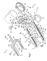
La
Ainsi, le dispositif de protection 10 inclut un ensemble 11 d'organes gonflables pouvant être gonflés dans des conditions prédéterminées par le constructeur du véhicule, afin de protéger l'individu assis sur le siège et notamment sa tête. Cet ensemble 11 d'organes gonflables 15, 20, 25 de protection est éventuellement disposé dans une enveloppe, l'enveloppe comprenant des zones fragilisées pour permettre le déploiement des organes gonflables de protection.Thus, the
Le dispositif de protection 10 comporte alors une têtière 35 pouvant être agencée sur le dossier 4 d'un siège 2, l'ensemble 11 d'organes gonflables étant fixé à la têtière 35.The
Pour gonfler l'ensemble 11 d'organes gonflables dans lesdites conditions prédéterminées, le dispositif de protection 10 est muni d'un gonfleur 30.To inflate the
Le gonfleur 30 peut contenir de l'hélium pressurisé et maintenu dans une chambre par une membrane. Par le biais d'un courant électrique, il est possible de détériorer la membrane pour permettre au fluide contenu de sortir du gonfleur par des orifices de distribution 31.The inflator 30 may contain pressurized helium and maintained in a chamber by a membrane. By means of an electric current, it is possible to damage the membrane to allow the contained fluid to exit the inflator through dispensing
A cet effet, le dispositif de protection 10 peut inclure un moyen d'activation 90 pour alimenter en courant électrique le gonfleur dans les conditions prédéterminées. Le moyen d'activation 90 comprend par exemple une batterie fournissant le courant électrique requis au gonfleur quand des capteurs détectent lesdites conditions.For this purpose, the
On comprend qu'il est possible d'utiliser tout type de gonfleur et le cas échéant de moyens d'activation pour gonfler à l'aide d'un fluide l'ensemble 11 d'organes gonflables.It is understood that it is possible to use any type of inflator and if necessary activation means for inflating with a fluid the
Le moyen d'activation peut être agencé sur un piètement du siège 2 et comprendre un moyen d'inhibition 91.The activation means can be arranged on a base of the seat 2 and comprise a means of
Pour acheminer le fluide du gonfleur 30 vers l'ensemble 11 d'organes gonflables, le dispositif de protection 10 est dépourvu de tuyaux d'acheminement pour faciliter son agencement et sa maintenance notamment.To route the fluid of the inflator 30 to the
Par conséquent, le dispositif de protection inclut un support creux 40 coopérant avec la têtière 35, le gonfleur 30 et un boîtier de diffusion 50.Therefore, the protection device includes a
Ce support creux 40 permet alors d'une part de fixer le gonfleur à la têtière et d'autre part d'acheminer le fluide du gonfleur vers les organes gonflables.This
En effet, le support creux 40 inclut un socle 41 coopérant avec une mâchoire 42. Cette mâchoire 42 comprend une première bague 43 solidaire du socle 41 et une deuxième bague 44.Indeed, the
La première bague 43 peut alors être fixée à la deuxième bague 44 par des moyens usuels pour enserrer le gonfleur 30.The
De plus, la mâchoire 42 comprend une gorge annulaire 45 ménagée par exemple dans la première bague et la deuxième bague. La gorge annulaire communique en outre avec un conduit 46 du socle 41.In addition, the
La gorge annulaire 45 est par suite placée en vis-à-vis des orifices de diffusion 31 du gonfleur 30. Le fluide s'échappant du gonfleur 30 par les orifices de diffusion 31 passe alors dans la gorge annulaire 45 puis dans le conduit 46.The
Par conséquent, la têtière comprend un perçage 36 coopérant avec le socle 41 et un orifice d'entrée 51 du boîtier de diffusion 50, ce boîtier de diffusion 50 étant fixé à une première face 35' de la têtière.Therefore, the headrest comprises a
Le boîtier de diffusion 50 inclut alors des sorties 52 communiquant avec l'orifice d'entrée 51 par des conduites internes, les orifices de sortie débouchant sur l'ensemble 11 d'organes gonflables.The
Selon une première variante, le socle 41 est fixé à une deuxième face 35" de la têtière afin que le perçage 36 soit en coïncidence du conduit 46.According to a first variant, the
Selon une deuxième variante, le socle 41 traverse le perçage 36 pour que le conduit 46 débouche sur l'orifice d'entrée 51. Des moyens de fixation peuvent de plus fixer le socle 41 à la deuxième face 35".In a second variant, the base 41 passes through the
Par ailleurs, l'ensemble 11 d'organes gonflables comprend un coussin de nuque 15 dans lequel est disposé le boîtier de diffusion 50. Le coussin de nuque 15 peut être fixé directement à la têtière ou indirectement par le biais du boîtier de diffusion 50.Furthermore, the
De plus, cet ensemble 11 inclut un moyen latéral gonflable gauche 20 et un moyen latéral gonflable droit 25 qui coopèrent respectivement avec la sangle d'épaule gauche 6 et la sangle d'épaule droite 7.In addition, this
De tels moyens latéraux gonflables sont parfois dénommés « seat belt airbag » en langue anglaise.Such inflatable lateral means are sometimes referred to as "seat belt airbag" in the English language.
Dès lors, le coussin de nuque 15 comporte au moins un passage gauche 16 et au moins un passage droit 17 pour acheminer le fluide de gonflage respectivement vers le moyen latéral gonflable gauche 20 et le moyen latéral gonflable droit 25.Therefore, the
Chaque moyen latéral gonflable 20, 25 inclut en outre un coussin inférieur 21, 26 et un coussin supérieur 22, 27, le coussin inférieur 21, 26 d'un moyen latéral gonflable donné communiquant avec le coussin de nuque 15 et le coussin supérieur 22, 27 associé à ce moyen latéral gonflable.Each inflatable lateral means 20, 25 further includes a
Selon une variante, chaque moyen latéral gonflable 20, 25 inclut seulement un coussin supérieur 22, 27 communiquant avec le coussin de nuque 15Alternatively, each inflatable lateral means 20, 25 includes only an
Les coussins supérieurs peuvent se rejoindre, une cloison étanche pouvant séparer les deux coussins supérieurs. De même, les coussins inférieurs peuvent se rejoindre selon une variante non représentée, une cloison étanche pouvant séparer les deux coussins inférieurs.The upper cushions can meet, a bulkhead separating the two upper cushions. Similarly, the lower cushions can meet in a variant not shown, a bulkhead can separate the two lower cushions.
Dès lors, les coussins latéraux supérieurs sont soit indépendants structurellement et fonctionnellement conformément à la réalisation de la
Par ailleurs et en référence à la
Chaque moyen de glissement a alors pour fonction de permettre un mouvement relatif entre le moyen latéral gonflable 20, 25 et une sangle d'épaule 6, 7 coopérant avec ce moyen latéral gonflable 20, 25.Each sliding means then has the function of allowing relative movement between the inflatable lateral means 20, 25 and a
En référence à la
Ce moyen de glissement peut comprendre un support 71 allongé, réalisé dans une matière flexible. Le support est éventuellement fixé à un coussin d'un moyen latéral gonflable et à une enveloppe du dispositif de protection.This sliding means may comprise an
Par ailleurs, ce support 71 porte une pluralité de guides 72 aptes à être traversés par une sangle d'épaule.Furthermore, this
Enfin, le support 71 est fixé à la têtière directement, ou indirectement par une section fusible 73 voire une liaison rotative 82 présente sur la
Par ailleurs, en référence à la
Le coussin inférieur ou le coussin supérieur peuvent alors être reliés au coussin de nuque. Il est intéressant de relier le coussin inférieur au coussin de nuque et le coussin supérieur au coussin inférieur afin que le coussin inférieur soit rapidement gonflé pour exercer une pré-tension sur la sangle associée.The lower cushion or the upper cushion can then be connected to the neck cushion. It is interesting to connect the lower cushion to the neck cushion and the upper cushion to the lower cushion so that the lower cushion is quickly inflated to pre-tension the associated strap.
En référence à la
De plus, la têtière 35 peut optionnellement comporter sur sa première face 35' une liaison rotative gauche 81 et une liaison rotative droite 82 traversées respectivement par une sangle d'épaule gauche 6 et une sangle d'épaule droite 7. Ainsi, la section fusible 73 de chaque moyen de glissement 70 est éventuellement fixée indirectement à la têtière 35 par une liaison rotative 81, 82.In addition, the
Chaque liaison rotative peut aussi être fixée au dossier du siège.Each rotary link can also be attached to the seat back.
En outre, en référence à la
De plus, le coussin de nuque 15 présente une face interne S3 en regard de la têtière 35 et une face externe S4 en regard des coussins latéraux supérieurs 22, 27.In addition, the
Par ailleurs, pour maximiser la protection d'un individu, le dispositif de protection 10 comprend un moyen de retenue 100 notamment pour retenir latéralement les coussins latéraux supérieurs 22, 27.Moreover, to maximize the protection of an individual, the
Ce moyen de retenue 100 comporte une sangle de retenue 110 et un dispositif de fixation 120 de la sangle de retenue 110 à la têtière 35.This retaining means 100 comprises a retaining
La sangle de retenue 110 est munie d'un corps de retenue 111. Ce corps de retenue 111 peut être un filet de retenue, ou encore être dépourvu de maillage.The retaining
De plus, le corps de retenue 111 peut avoir une forme de C. Dès lors, le corps inclut un fond 116 et deux branches latérales 112, 113.In addition, the retaining body 111 may have a C shape. As a result, the body includes a bottom 116 and two
La forme des branches latérales peut être optimisée pour minimiser la masse de la sangle de retenue. Chaque branche latérale peut avoir une hauteur maximale à proximité de la tête d'un individu notamment. Ainsi, chaque branche latérale peut avoir une forme triangulaire afin de présenter une hauteur qui décroit en partant du fond 116 du corps 111.The shape of the side branches can be optimized to minimize the weight of the retaining strap. Each side branch can have a maximum height near the head of an individual in particular. Thus, each lateral branch may have a triangular shape in order to have a height that decreases starting from the
Selon un autre aspect, la sangle de retenue 110 peut comprendre un flanc de fixation gauche 114 fixé au moyen de glissement gauche 70', et un flanc de fixation droit 115 fixé au moyen de glissement droit 70" par des moyens usuels.In another aspect, the retaining
Par exemple, chaque branche latérale 112, 113 de la sangle de retenue 110 est prolongée par un flanc de fixation pour être fixé à un moyen de glissement.For example, each
De plus, la sangle de retenue peut être fixée, au moins localement à une surface externe S2 d'un coussin latéral supérieur. Le gonflement des coussins latéraux supérieurs entraîne alors le déploiement de la sangle de retenue.In addition, the retaining strap may be attached, at least locally to an outer surface S2 of an upper side cushion. The swelling of the upper side cushions then causes the deployment of the retaining strap.
Par ailleurs, la sangle de retenue 110 peut être fixée à la face externe S4 du coussin de nuque.Furthermore, the retaining
Par exemple, une partie haute du coussin de nuque étant fixée à la têtière, le fond 116 du corps 111 est fixé à une partie basse du coussin de nuque qui est mobile par rapport à la têtière.For example, an upper part of the neck cushion being attached to the headrest, the
Selon un autre aspect, le dispositif de fixation 120 peut comporter une sangle de fixation 121 solidaire de la sangle de retenue 110. Une telle sangle de fixation peut s'étendre longitudinalement vers la têtière 35 à partir du fond 116 du corps 111 de la sangle de retenue.In another aspect, the fixing
Cette sangle de fixation 121 coopère avec un logement de fixation 125 du dispositif de fixation.This
Ce logement de fixation est ménagé dans la têtière 35. Ainsi, le logement de fixation 125 possède un orifice de sortie 126 qui est traversé par la sangle de fixation 121.This fixing housing is formed in the
Cet orifice de sortie 126 présente une partie centrale 127 disposée entre deux parties extrêmales 128. La partie centrale 127 a une première épaisseur e1 constante, alors que chaque partie extrémale 128 comporte une deuxième épaisseur e2 qui décroit à partir de la partie centrale 127 pour former un moyen de blocage latéral de la sangle de retenue.This
En outre, la sangle de fixation 121 inclut une pluralité d'inserts 122, tels que des inserts cylindriques. Chaque insert 122 a une épaisseur caractéristique inférieure à la première épaisseur e1 et supérieure à ladite deuxième épaisseur e2. Dans le cadre d'un insert cylindrique, cette épaisseur caractéristique peut être le diamètre de l'insert.In addition, the
La
La sangle de retenue est alors pliée contre les coussins latéraux supérieurs 22, 27, et les coussins latéraux inférieurs 21, 26.The retaining strap is then folded against the upper side cushions 22, 27, and the lower side cushions 21, 26.
La
La sangle de retenue est alors accolée à la surface externe S2 des coussins latéraux supérieurs 22, 27.The retaining strap is then contiguous to the outer surface S2 of the upper lateral cushions 22, 27.
On note que le coussin de nuque n'est pas fixé à la têtière sur la
Bien que schématique, cette représentation présente l'avantage de montrer l'insertion d'une partie de la sangle de fixation 121 dans le logement de fixation 125.Although schematic, this representation has the advantage of showing the insertion of a portion of the
La
Le dispositif de fixation 120 comporte un système de fixation temporaire pour fixer cette sangle de fixation à une paroi du logement de fixation tant que la tension de la sangle de fixation est inférieure à un seuil.The
Par exemple, un tel système de fixation temporaire est muni d'un système auto-agrippant 130.For example, such a temporary fastening system is provided with a self-gripping
Ce système auto-agrippant 130 comporte un premier moyen auto-agrippant 131 fixé sur la sangle de fixation 121 en vis-à-vis du logement de fixation sous chaque insert 122. De plus, le système auto-agrippant 130 est pourvu d'un deuxième moyen auto-agrippant 132 fixé sur une paroi du logement de fixation 125 pour coopérer par interférence de forme avec chaque premier moyen auto-agrippant 131.This self-gripping
Eventuellement, le premier moyen auto-agrippant 131 comporte une première bande auto-agrippante par insert. Le deuxième moyen auto-agrippant 132 peut comporter une deuxième bande auto-agrippante par première bande, ou une unique deuxième bande coopérant avec toutes les premières bandes.Optionally, the first self-gripping
Dès lors, une bande peut comporter des crochets, l'autre bande ayant des boucles aptes à être saisies par lesdits crochets.Therefore, one band may comprise hooks, the other band having loops adapted to be gripped by said hooks.
De plus, la sangle de fixation 121 incluant une pluralité d'inserts 122 séparés deux à deux par une portion de sangle 123, chaque portion de sangle 123 séparant deux inserts 122 au sein d'un logement est pliéeIn addition, the
Par suite, préalablement à un incident, chaque moyen latéral gonflable se trouve dans une position non gonflée.As a result, prior to an incident, each inflatable lateral means is in an uninflated position.
Par contre, si un incident se produit selon des conditions prédéterminées par le constructeur, le gonfleur 30 expulse un fluide par ses orifices de diffusion 31.On the other hand, if an incident occurs under conditions predetermined by the manufacturer, the
Ce fluide traverse le support 40 puis le boîtier de diffusion 50 pour se répandre dans le coussin de nuque 15, ce coussin de nuque 15 étant par suite gonflé.This fluid passes through the
En parallèle, une partie du fluide passe du coussin de nuque 15 vers les moyens latéraux gonflables 20, 25 en traversant les passages 16, 17 restreints du coussin de nuque prévus à cet effet.In parallel, a portion of the fluid passes from the
Plus particulièrement, le fluide pénètre dans les coussins inférieurs 21, 26 le cas échéant, puis rejoint les coussins supérieurs 22, 27.More particularly, the fluid enters the
Par conséquent, le dispositif de protection 10 passe d'un premier état dit « non gonflé » vers un état dit « gonflé ».Therefore, the
Le gonflement des moyens latéraux gonflables 20, 25 induit de plus le déploiement de la sangle de retenue 110, la sangle de retenue étant accolée à la surface externe des coussins latéraux supérieurs.The swelling of the inflatable lateral means 20, 25 further induces the deployment of the retaining
A ce stade, les moyens latéraux gonflables 20, 25 et notamment les coussins inférieurs 21, 26 exercent une force de friction sur l'individu.At this stage, the inflatable lateral means 20, 25 and in particular the
En référence à la
Les forces de friction évoquées précédemment tendent à maintenir les moyens latéraux gonflables contre le buste.The aforementioned frictional forces tend to maintain the inflatable lateral means against the bust.
Toutefois, une force de traction représentée par la flèche F1 est exercée notamment sur les zones fusibles 73 des moyens de glissement 70. A compter d'un seuil, les zones fusibles sont rompues. Il en résulte que les moyens latéraux gonflables se déplacent conjointement avec le buste de l'individu en s'éloignant du dossier 4 et de la têtière 35 pour continuer à protéger cet individu.However, a tensile force represented by the arrow F1 is exerted in particular on the
Par contre, le coussin de nuque reste fixé au moins partiellement à cette têtière 35.On the other hand, the neck cushion remains fixed at least partially to this
Par conséquent, quand le buste de l'individu revient vers le dossier 4 à l'issue de son mouvement vers l'avant, le coussin de nuque reste en position pour minimiser un contact éventuel entre la nuque de l'individu et la têtière 35.Therefore, when the bust of the individual returns to the
De plus, en référence à la
En outre, la sangle de retenue tend à se déplacer vers l'avant conjointement avec les moyens de guidage 70. Le système auto-agrippant 130 qui coopère avec la sangle de fixation 121 induit alors la création d'une force de retenue représentée par la flèche F2.In addition, the retaining strap tends to move forwardly together with the guide means 70. The self-gripping
A partir d'un seuil, l'insert le plus proche de l'orifice de sortie se désolidarise de la paroi du logement. La portion de sangle pliée solidaire de cet insert se déplie. Cependant, en fonction de la valeur des forces d'inertie longitudinales, l'insert suivant peut rester fixé au logement.From a threshold, the insert closest to the outlet orifice is disengaged from the housing wall. The portion of folded strap integral with this insert unfolds. However, depending on the value of the longitudinal inertia forces, the next insert can remain attached to the housing.
L'invention peut alors comprendre une pluralité d'inserts pour optimiser son fonctionnement.The invention may then comprise a plurality of inserts to optimize its operation.
En référence à la
Par contre, en référence à la
En référence à la
Les inserts empêchent alors la sangle de fixation de s'échapper du logement de fixation 125.The inserts then prevent the fastening strap from escaping from the fixing
La
Sur un dispositif dépourvu de l'invention, la tête d'un individu peut parcourir un secteur angulaire α0 avant d'entrer en contact avec un coussin latéral supérieur. En effet, en l'absence de l'invention, ce coussin latéral supérieur peut se déplacer et augmenter la liberté de mouvement de la tête.On a device devoid of the invention, the head of an individual can traverse an angular sector α0 before coming into contact with an upper side cushion. Indeed, in the absence of the invention, this upper lateral cushion can move and increase the freedom of movement of the head.
Par contre, en référence à la
En référence à la
En effet, les efforts représentés par les flèches F7 exercés sur le moyen du guidage sous l'effet de la pression du fluide dans les coussins latéraux supérieurs et sous l'effet des forces d'inertie latérales induisent une importante friction. Les forces de friction sont représentées par la flèche F6.Indeed, the forces represented by the arrows F7 exerted on the guide means under the effect of the pressure of the fluid in the upper side cushions and under the effect of lateral inertia forces induce a high friction. The friction forces are represented by the arrow F6.
Cette friction va alors favorablement à l'encontre dudit déplacement.This friction then favors against said displacement.
Naturellement, la présente invention est sujette à de nombreuses variations quant à sa mise en oeuvre. Bien que plusieurs modes de réalisation aient été décrits, on comprend bien qu'il n'est pas concevable d'identifier de manière exhaustive tous les modes possibles. Il est bien sûr envisageable de remplacer un moyen décrit par un moyen équivalent sans sortir du cadre de la présente invention.Naturally, the present invention is subject to many variations as to its implementation. Although several embodiments have been described, it is well understood that it is not conceivable to exhaustively identify all the possible modes. It is of course conceivable to replace a means described by equivalent means without departing from the scope of the present invention.
Claims (16)
caractérisé en ce que ledit dispositif de protection (10) possède un moyen de retenue (100) pour retenir latéralement lesdits coussins latéraux supérieurs (22, 27), ledit moyen de retenue (100) comportant une sangle de retenue (110) accolée à la surface externe (S2) desdits coussins latéraux supérieurs (22, 27), ledit moyen de retenue (100) ayant un dispositif de fixation (120) de ladite sangle de retenue (110) à la têtière (35).Protective device (10) of an individual held on a seat (2) of a vehicle by means of a harness (5) comprising a left shoulder strap (6) and a right shoulder strap ( 7), said device (10) having a headrest (35) carrying an assembly (11) of inflatable protection members including a neck cushion (15) and a left inflatable lateral means (20) and an inflatable lateral means right (25), said protective device (10) having an inflatable lateral means (70) (20, 25) which can be traversed by a shoulder strap (6, 7) to allow relative movement between said inflatable lateral means (20, 25) and a shoulder strap (6, 7), said neck cushion (15) being attached to the headrest (35) and communicating with each inflatable lateral means (20, 25), each means inflatable sidewall (20, 25) having an upper side cushion (22, 27) attached to a sliding means (70), each upper side cushion (22, 27). ) having an inner surface (S1) adapted to be in contact with the head of the individual and an outer surface (S2) opposite to the inner surface (S1),
characterized in that said protection device (10) has a retaining means (100) for laterally retaining said upper lateral cushions (22, 27), said retaining means (100) having a retaining strap (110) contiguous to the outer surface (S2) of said upper side cushions (22, 27), said retaining means (100) having a fastener (120) of said retaining strap (110) to the headrest (35).
caractérisé en ce que les coussins latéraux supérieurs (22, 27) sont soit indépendants structurellement et fonctionnellement, soit accolés structurellement l'un à l'autre mais fonctionnellement indépendants, soit fusionnés de manière à former un unique coussin.Protective device according to claim 1,
characterized in that the upper side cushions (22, 27) are either structurally and functionally independent, or structurally joined to one another but functionally independent, or fused together to form a single cushion.
caractérisé en ce que ladite sangle de retenue (110) comporte un corps de retenue englobant chaque coussin latéral supérieur (22, 27), le corps de retenue étant plein de manière à être dépourvu de maille creuse.Protective device according to one of Claims 1 to 2,
characterized in that said retaining strap (110) comprises a retaining body including each upper side cushion (22,27), the retaining body being solid so as to be free of hollow mesh.
caractérisé en ce que ladite sangle de retenue (110) comporte un maillage plaqué contre les surfaces externes des coussins latéraux supérieursProtective device according to one of Claims 1 to 2,
characterized in that said retaining strap (110) has a mesh pressed against the outer surfaces of the upper side cushions
caractérisé en ce que, ledit dispositif de protection (10) comportant un moyen de glissement gauche (70') coopérant avec un moyen latéral gonflable gauche (20) et un moyen de glissement droit (70") coopérant avec un moyen latéral gonflable droit (25), ladite sangle de retenue (110) comporte un flanc de fixation gauche (114) fixé au moyen de glissement gauche (70') et un flanc de fixation droit (115) fixé au moyen de glissement droit (70").Protective device according to one of Claims 1 to 4,
characterized in that said protective device (10) having a left sliding means (70 ') cooperating with a left inflatable lateral means (20) and a right sliding means (70 ") cooperating with a right inflatable lateral means ( 25), said retaining strap (110) has a left fixing flank (114) fixed to the left sliding means (70 ') and a right fixing flank (115) fixed to the right gliding means (70 ").
caractérisé en ce que ladite sangle de retenue (110) est fixée à une surface externe (S2) de chaque coussin latéral supérieur (22, 27).Protective device according to one of Claims 1 to 5,
characterized in that said retaining strap (110) is attached to an outer surface (S2) of each upper side cushion (22, 27).
caractérisé en ce que, ledit coussin de nuque (15) ayant une face interne (S3) en regard de la têtière (35) et une face externe (S4) en regard des coussins latéraux supérieurs (22, 27), ladite sangle de retenue (110) est fixée à ladite face externe (S4).Protective device according to one of Claims 1 to 6,
characterized in that , said neck cushion (15) having an inner face (S3) facing the headrest (35) and an outer face (S4) facing the upper side cushions (22, 27), said retention strap (110) is attached to said outer face (S4).
caractérisé en ce que ledit dispositif de fixation (120) comporte une sangle de fixation (121) solidaire de ladite sangle de retenue (110) ainsi qu'un logement de fixation (125) ménagé dans la têtière (35), ledit logement de fixation (125) comportant un orifice de sortie (126) traversé par ladite sangle de fixation (121).Protective device according to one of Claims 1 to 7,
characterized in that said fixing device (120) comprises a fastening strap (121) integral with said retaining strap (110) as well as a fixing housing (125) formed in the headrest (35), said fixing housing (125) having an outlet port (126) traversed by said attachment strap (121).
caractérisé en ce que ledit orifice de sortie (126) présente une partie centrale (127) comprise entre deux parties extrêmales (128), ladite partie centrale (127) ayant une première épaisseur (e1) constante, et chaque partie extrémale (128) ayant une deuxième épaisseur (e2) décroissant à partir de la partie centrale (127) pour former un moyen de blocage latéral de la sangle de retenue.Protective device according to claim 8,
characterized in that said outlet (126) has a central portion (127) between two end portions (128), said central portion (127) having a first constant thickness (e1), and each end portion (128) having a second thickness (e2) decreasing from the central portion (127) to form a lateral locking means of the retaining strap.
caractérisé en ce que chaque moyen de glissement (70) étant fixé par une section fusible (73) à ladite têtière (35), ladite sangle de fixation (121) inclut une pluralité d'inserts (122), chaque insert (122) ayant une épaisseur inférieure à ladite première épaisseur (e1) pour pouvoir s'échapper dudit logement de fixation (125) via ladite partie centrale (126) sous l'effet de forces d'inertie entraînant la rupture de ladite section fusible (73), chaque insert (122) ayant une épaisseur supérieure à ladite deuxième épaisseur (e2) afin de ne pas pouvoir s'échapper dudit logement de fixation (125) via une partie extrémale (128).Protective device according to claim 9,
characterized in that each slip means (70) being secured by a fuse section (73) to said headrest (35), said fastening strap (121) includes a plurality of inserts (122), each insert (122) having a thickness less than said first thickness (e1) to be able to escape from said fixing housing (125) via said central portion (126) under the effect of inertial forces causing the breaking of said fuse section (73), each insert (122) having a thickness greater than said second thickness (e2) so as not to be able to escape from said fixing housing (125) via an end portion (128).
caractérisé en ce que, ladite sangle de fixation (121) incluant une pluralité d'inserts (122), ledit dispositif de fixation (120) est muni d'un système auto-agrippant (130) comportant un premier moyen auto-agrippant (131) fixé sur la sangle de fixation (121) en vis-à-vis du logement de fixation sous chaque insert (122), ledit système auto-agrippant (130) comportant un deuxième moyen auto-agrippant (132) fixé sur une paroi dudit logement de fixation (125) coopérant par interférence de forme avec chaque premier moyen auto-agrippant (131).Protective device according to one of Claims 8 to 10,
characterized in that , said fastening strap (121) including a plurality of inserts (122), said fastening device (120) is provided with a self-gripping system (130) having a first self-gripping means (131) ) fixed on the fastening strap (121) vis-à-vis the fixing housing under each insert (122), said self-gripping system (130) comprising a second self-gripping means (132) fixed on a wall of said fixing housing (125) cooperating by interference of form with each first self-gripping means (131).
caractérisé en ce que ladite sangle de fixation (121) incluant une pluralité d'inserts (122) séparés deux à deux par une portion de sangle (123), chaque portion de sangle (123) séparant deux inserts (122) au sein d'un logement est pliée.Protective device according to one of Claims 8 to 11,
characterized in that said fastening strap (121) including a plurality of inserts (122) separated in pairs by a strap portion (123), each strap portion (123) separating two inserts (122) within a home is folded.
caractérisé en ce que chaque moyen latéral gonflable (20, 25) comporte un coussin latéral inférieur (21, 266).Protective device according to one of Claims 1 to 12,
characterized in that each inflatable lateral means (20, 25) comprises a lower side cushion (21, 266).
caractérisé en ce que ladite têtière (35) comporte un gonfleur.Protective device according to one of Claims 1 to 13,
characterized in that said headrest (35) comprises an inflator.
caractérisé en ce que ledit siège comporte un dispositif de protection (10) selon l'une quelconque des revendications 1 à 14.Seat (2) provided with a backrest (4) and an attachment harness (5) of an individual comprising a left shoulder strap (6) and a right shoulder strap (7),
characterized in that said seat comprises a protection device (10) according to any one of claims 1 to 14.
caractérisé en ce qu'il comporte au moins un siège (2) selon la revendication 15.Vehicle (1),
characterized in that it comprises at least one seat (2) according to claim 15.
Applications Claiming Priority (1)
| Application Number | Priority Date | Filing Date | Title |
|---|---|---|---|
| FR1201635A FR2991644B1 (en) | 2012-06-06 | 2012-06-06 | DEVICE FOR PROTECTING AN INDIVIDUAL SITTING ON A SEAT, SEAT AND VEHICLE |
Publications (3)
| Publication Number | Publication Date |
|---|---|
| EP2671802A2 true EP2671802A2 (en) | 2013-12-11 |
| EP2671802A3 EP2671802A3 (en) | 2015-07-01 |
| EP2671802B1 EP2671802B1 (en) | 2016-05-25 |
Family
ID=46754502
Family Applications (1)
| Application Number | Title | Priority Date | Filing Date |
|---|---|---|---|
| EP13001781.7A Active EP2671802B1 (en) | 2012-06-06 | 2013-04-08 | Device for protecting a person sitting on a seat, seat and vehicle |
Country Status (2)
| Country | Link |
|---|---|
| EP (1) | EP2671802B1 (en) |
| FR (1) | FR2991644B1 (en) |
Cited By (3)
| Publication number | Priority date | Publication date | Assignee | Title |
|---|---|---|---|---|
| EP2918498A1 (en) * | 2014-03-11 | 2015-09-16 | Airbus Helicopters | A device for protecting an individual sitting on a seat, a seat, and a vehicle |
| US10336278B2 (en) * | 2017-07-14 | 2019-07-02 | Autoliv Asp, Inc. | Inflatable airbag harness assemblies |
| CN112937491A (en) * | 2021-04-07 | 2021-06-11 | 美棒技术(上海)有限公司 | Automobile with a detachable front cover |
Citations (10)
| Publication number | Priority date | Publication date | Assignee | Title |
|---|---|---|---|---|
| EP0592815A1 (en) | 1992-10-10 | 1994-04-20 | Audi Ag | Headrest for passengers of vehicles |
| WO2006133739A1 (en) | 2005-06-17 | 2006-12-21 | Dalphi Metal España, S.A. | Automotive vehicle seat with an airbag in the backrest thereof |
| US20070001435A1 (en) | 2005-06-29 | 2007-01-04 | Takata Seat Belt, Inc | Seat belt system including an airbag |
| EP1818222A1 (en) | 2006-02-09 | 2007-08-15 | Toyota Jidosha Kabushiki Kaisha | Vehicle airbelt apparatus |
| JP2007276514A (en) | 2006-04-03 | 2007-10-25 | Nissan Motor Co Ltd | Occupant protection device and occupant protection method of vehicle |
| EP1987991A1 (en) | 2006-02-09 | 2008-11-05 | Toyota Jidosha Kabushiki Kaisha | Air belt device for vehicle |
| DE102008028653A1 (en) | 2008-06-18 | 2009-12-24 | Schmitz, Josef | Human's i.e. pilot, head and/or neck spinal column supporting device for use in airplane, has compressed cushion part arranged in neck area of human, and another compressed cushion part connected with former cushion part over pressure line |
| US7665761B1 (en) | 2008-03-27 | 2010-02-23 | Amsafe, Inc. | Inflatable personal restraint systems and associated methods of use and manufacture |
| DE102009040641A1 (en) | 2008-09-15 | 2010-04-15 | Takata-Petri Ag | Airbag device for vehicle seat of vehicle, has airbag and gas generator for inflating airbag, where airbag device is arranged in or on headrest of vehicle seat |
| WO2012013985A1 (en) | 2010-07-30 | 2012-02-02 | Martin-Baker Aircraft Co Ltd | A headrest assembly |
-
2012
- 2012-06-06 FR FR1201635A patent/FR2991644B1/en not_active Expired - Fee Related
-
2013
- 2013-04-08 EP EP13001781.7A patent/EP2671802B1/en active Active
Patent Citations (10)
| Publication number | Priority date | Publication date | Assignee | Title |
|---|---|---|---|---|
| EP0592815A1 (en) | 1992-10-10 | 1994-04-20 | Audi Ag | Headrest for passengers of vehicles |
| WO2006133739A1 (en) | 2005-06-17 | 2006-12-21 | Dalphi Metal España, S.A. | Automotive vehicle seat with an airbag in the backrest thereof |
| US20070001435A1 (en) | 2005-06-29 | 2007-01-04 | Takata Seat Belt, Inc | Seat belt system including an airbag |
| EP1818222A1 (en) | 2006-02-09 | 2007-08-15 | Toyota Jidosha Kabushiki Kaisha | Vehicle airbelt apparatus |
| EP1987991A1 (en) | 2006-02-09 | 2008-11-05 | Toyota Jidosha Kabushiki Kaisha | Air belt device for vehicle |
| JP2007276514A (en) | 2006-04-03 | 2007-10-25 | Nissan Motor Co Ltd | Occupant protection device and occupant protection method of vehicle |
| US7665761B1 (en) | 2008-03-27 | 2010-02-23 | Amsafe, Inc. | Inflatable personal restraint systems and associated methods of use and manufacture |
| DE102008028653A1 (en) | 2008-06-18 | 2009-12-24 | Schmitz, Josef | Human's i.e. pilot, head and/or neck spinal column supporting device for use in airplane, has compressed cushion part arranged in neck area of human, and another compressed cushion part connected with former cushion part over pressure line |
| DE102009040641A1 (en) | 2008-09-15 | 2010-04-15 | Takata-Petri Ag | Airbag device for vehicle seat of vehicle, has airbag and gas generator for inflating airbag, where airbag device is arranged in or on headrest of vehicle seat |
| WO2012013985A1 (en) | 2010-07-30 | 2012-02-02 | Martin-Baker Aircraft Co Ltd | A headrest assembly |
Cited By (4)
| Publication number | Priority date | Publication date | Assignee | Title |
|---|---|---|---|---|
| EP2918498A1 (en) * | 2014-03-11 | 2015-09-16 | Airbus Helicopters | A device for protecting an individual sitting on a seat, a seat, and a vehicle |
| US9745065B2 (en) | 2014-03-11 | 2017-08-29 | Airbus Helicopters | Device for protecting an individual sitting on a seat, a seat, and a vehicle |
| US10336278B2 (en) * | 2017-07-14 | 2019-07-02 | Autoliv Asp, Inc. | Inflatable airbag harness assemblies |
| CN112937491A (en) * | 2021-04-07 | 2021-06-11 | 美棒技术(上海)有限公司 | Automobile with a detachable front cover |
Also Published As
| Publication number | Publication date |
|---|---|
| EP2671802A3 (en) | 2015-07-01 |
| EP2671802B1 (en) | 2016-05-25 |
| FR2991644B1 (en) | 2014-07-04 |
| FR2991644A1 (en) | 2013-12-13 |
Similar Documents
| Publication | Publication Date | Title |
|---|---|---|
| JP6269619B2 (en) | Vehicle seat belt device and occupant protection device | |
| US8807591B2 (en) | Vehicle seat and webbing sewing method | |
| US6179383B1 (en) | Child seat | |
| US8714589B2 (en) | Device for protecting an individual sitting on a seat, a seat, and a vehicle | |
| EP2303645B1 (en) | Inflatable seat belt system | |
| US9022424B2 (en) | Airbag device | |
| US20200254953A1 (en) | Modular restraint seat for vehicle with one or more integrated safety features | |
| EP2804788B1 (en) | Protecting device for the head and the neck of an idividual | |
| EP1193141B1 (en) | Vehicle seat comprising a headrest and an inflatable cushion inside the headrest | |
| FR3014387A1 (en) | ||
| EP2671802B1 (en) | Device for protecting a person sitting on a seat, seat and vehicle | |
| FR2969055A1 (en) | PUERICULTURE DEVICE COMPRISING INFLATABLE SAFETY ELEMENTS | |
| EP3247594B1 (en) | Pyrotechnic gas generator and respective childcare device | |
| US11904792B2 (en) | Seat-centric airbag system with active pelvis restraint | |
| JP4581942B2 (en) | Crew restraint system | |
| EP2481643B1 (en) | Vehicule-occupant protection device, seat and vehicle, associated seat and vehicle | |
| EP3459853B1 (en) | Safety device for equipping a paraglider or aircraft seat, and seat equipped with such a device | |
| EP3815988B1 (en) | Vehicle seat provided with a device for protecting the thorax | |
| CN215971413U (en) | Seat and vehicle | |
| EP2782795B1 (en) | Airbag device having a deflector and a bag-supporting flange | |
| FR3102733A1 (en) | seat belt with airbag deployment mechanism | |
| FR2928598A1 (en) | Safety belt for protecting occupant in e.g. seat of motor vehicle, has extension mechanism including splitting mechanism that is constituted of slide and splits upper anchoring point by separating upper and lower parts of upper point | |
| FR2982817A1 (en) | Side impact airbag safety device for use on reinforcement of backrest of seat of car, has compression units compressed to impregnate curve with device, where curve is oriented toward fastener and adapted to integration of device | |
| FR2918328A1 (en) | Safety belt for motor vehicle, has ventral strap integrated with inflatable safety cushion, where cushion has deployment units to deploy cushion towards front and top during inflation, by minimizing pressure at front region of cushion | |
| FR3094936A1 (en) | PROTECTION DEVICE WITH INFLATABLE BAGS COUPLED BY A STRESS STRAP, FOR A VEHICLE DASHBOARD |
Legal Events
| Date | Code | Title | Description |
|---|---|---|---|
| PUAI | Public reference made under article 153(3) epc to a published international application that has entered the european phase |
Free format text: ORIGINAL CODE: 0009012 |
|
| AK | Designated contracting states |
Kind code of ref document: A2 Designated state(s): AL AT BE BG CH CY CZ DE DK EE ES FI FR GB GR HR HU IE IS IT LI LT LU LV MC MK MT NL NO PL PT RO RS SE SI SK SM TR |
|
| AX | Request for extension of the european patent |
Extension state: BA ME |
|
| RAP1 | Party data changed (applicant data changed or rights of an application transferred) |
Owner name: AIRBUS HELICOPTERS |
|
| PUAL | Search report despatched |
Free format text: ORIGINAL CODE: 0009013 |
|
| AK | Designated contracting states |
Kind code of ref document: A3 Designated state(s): AL AT BE BG CH CY CZ DE DK EE ES FI FR GB GR HR HU IE IS IT LI LT LU LV MC MK MT NL NO PL PT RO RS SE SI SK SM TR |
|
| AX | Request for extension of the european patent |
Extension state: BA ME |
|
| RIC1 | Information provided on ipc code assigned before grant |
Ipc: B60R 22/02 20060101ALI20150528BHEP Ipc: B60R 21/18 20060101ALI20150528BHEP Ipc: B64D 11/06 20060101ALI20150528BHEP Ipc: B60R 21/207 20060101ALI20150528BHEP Ipc: B64D 25/06 20060101AFI20150528BHEP Ipc: B60R 21/201 20110101ALI20150528BHEP Ipc: B60N 2/48 20060101ALI20150528BHEP Ipc: B60R 22/00 20060101ALI20150528BHEP |
|
| 17P | Request for examination filed |
Effective date: 20150827 |
|
| RBV | Designated contracting states (corrected) |
Designated state(s): AL AT BE BG CH CY CZ DE DK EE ES FI FR GB GR HR HU IE IS IT LI LT LU LV MC MK MT NL NO PL PT RO RS SE SI SK SM TR |
|
| RIC1 | Information provided on ipc code assigned before grant |
Ipc: B64D 11/06 20060101ALI20151215BHEP Ipc: B60N 2/48 20060101ALI20151215BHEP Ipc: B60R 22/02 20060101ALI20151215BHEP Ipc: B64D 25/06 20060101AFI20151215BHEP Ipc: B60R 21/207 20060101ALI20151215BHEP Ipc: B60R 21/201 20110101ALI20151215BHEP Ipc: B60R 22/00 20060101ALI20151215BHEP Ipc: B60R 21/18 20060101ALI20151215BHEP |
|
| GRAP | Despatch of communication of intention to grant a patent |
Free format text: ORIGINAL CODE: EPIDOSNIGR1 |
|
| INTG | Intention to grant announced |
Effective date: 20160125 |
|
| GRAS | Grant fee paid |
Free format text: ORIGINAL CODE: EPIDOSNIGR3 |
|
| GRAA | (expected) grant |
Free format text: ORIGINAL CODE: 0009210 |
|
| AK | Designated contracting states |
Kind code of ref document: B1 Designated state(s): AL AT BE BG CH CY CZ DE DK EE ES FI FR GB GR HR HU IE IS IT LI LT LU LV MC MK MT NL NO PL PT RO RS SE SI SK SM TR |
|
| REG | Reference to a national code |
Ref country code: GB Ref legal event code: FG4D Free format text: NOT ENGLISH |
|
| REG | Reference to a national code |
Ref country code: CH Ref legal event code: EP |
|
| REG | Reference to a national code |
Ref country code: IE Ref legal event code: FG4D Free format text: LANGUAGE OF EP DOCUMENT: FRENCH Ref country code: AT Ref legal event code: REF Ref document number: 802073 Country of ref document: AT Kind code of ref document: T Effective date: 20160615 |
|
| REG | Reference to a national code |
Ref country code: DE Ref legal event code: R096 Ref document number: 602013007779 Country of ref document: DE |
|
| REG | Reference to a national code |
Ref country code: LT Ref legal event code: MG4D |
|
| REG | Reference to a national code |
Ref country code: NL Ref legal event code: MP Effective date: 20160525 |
|
| PG25 | Lapsed in a contracting state [announced via postgrant information from national office to epo] |
Ref country code: NO Free format text: LAPSE BECAUSE OF FAILURE TO SUBMIT A TRANSLATION OF THE DESCRIPTION OR TO PAY THE FEE WITHIN THE PRESCRIBED TIME-LIMIT Effective date: 20160825 Ref country code: NL Free format text: LAPSE BECAUSE OF FAILURE TO SUBMIT A TRANSLATION OF THE DESCRIPTION OR TO PAY THE FEE WITHIN THE PRESCRIBED TIME-LIMIT Effective date: 20160525 Ref country code: FI Free format text: LAPSE BECAUSE OF FAILURE TO SUBMIT A TRANSLATION OF THE DESCRIPTION OR TO PAY THE FEE WITHIN THE PRESCRIBED TIME-LIMIT Effective date: 20160525 Ref country code: LT Free format text: LAPSE BECAUSE OF FAILURE TO SUBMIT A TRANSLATION OF THE DESCRIPTION OR TO PAY THE FEE WITHIN THE PRESCRIBED TIME-LIMIT Effective date: 20160525 |
|
| REG | Reference to a national code |
Ref country code: AT Ref legal event code: MK05 Ref document number: 802073 Country of ref document: AT Kind code of ref document: T Effective date: 20160525 |
|
| PG25 | Lapsed in a contracting state [announced via postgrant information from national office to epo] |
Ref country code: PT Free format text: LAPSE BECAUSE OF FAILURE TO SUBMIT A TRANSLATION OF THE DESCRIPTION OR TO PAY THE FEE WITHIN THE PRESCRIBED TIME-LIMIT Effective date: 20160926 Ref country code: SE Free format text: LAPSE BECAUSE OF FAILURE TO SUBMIT A TRANSLATION OF THE DESCRIPTION OR TO PAY THE FEE WITHIN THE PRESCRIBED TIME-LIMIT Effective date: 20160525 Ref country code: LV Free format text: LAPSE BECAUSE OF FAILURE TO SUBMIT A TRANSLATION OF THE DESCRIPTION OR TO PAY THE FEE WITHIN THE PRESCRIBED TIME-LIMIT Effective date: 20160525 Ref country code: RS Free format text: LAPSE BECAUSE OF FAILURE TO SUBMIT A TRANSLATION OF THE DESCRIPTION OR TO PAY THE FEE WITHIN THE PRESCRIBED TIME-LIMIT Effective date: 20160525 Ref country code: GR Free format text: LAPSE BECAUSE OF FAILURE TO SUBMIT A TRANSLATION OF THE DESCRIPTION OR TO PAY THE FEE WITHIN THE PRESCRIBED TIME-LIMIT Effective date: 20160826 Ref country code: ES Free format text: LAPSE BECAUSE OF FAILURE TO SUBMIT A TRANSLATION OF THE DESCRIPTION OR TO PAY THE FEE WITHIN THE PRESCRIBED TIME-LIMIT Effective date: 20160525 |
|
| PG25 | Lapsed in a contracting state [announced via postgrant information from national office to epo] |
Ref country code: CZ Free format text: LAPSE BECAUSE OF FAILURE TO SUBMIT A TRANSLATION OF THE DESCRIPTION OR TO PAY THE FEE WITHIN THE PRESCRIBED TIME-LIMIT Effective date: 20160525 Ref country code: SK Free format text: LAPSE BECAUSE OF FAILURE TO SUBMIT A TRANSLATION OF THE DESCRIPTION OR TO PAY THE FEE WITHIN THE PRESCRIBED TIME-LIMIT Effective date: 20160525 Ref country code: RO Free format text: LAPSE BECAUSE OF FAILURE TO SUBMIT A TRANSLATION OF THE DESCRIPTION OR TO PAY THE FEE WITHIN THE PRESCRIBED TIME-LIMIT Effective date: 20160525 Ref country code: EE Free format text: LAPSE BECAUSE OF FAILURE TO SUBMIT A TRANSLATION OF THE DESCRIPTION OR TO PAY THE FEE WITHIN THE PRESCRIBED TIME-LIMIT Effective date: 20160525 Ref country code: DK Free format text: LAPSE BECAUSE OF FAILURE TO SUBMIT A TRANSLATION OF THE DESCRIPTION OR TO PAY THE FEE WITHIN THE PRESCRIBED TIME-LIMIT Effective date: 20160525 |
|
| PG25 | Lapsed in a contracting state [announced via postgrant information from national office to epo] |
Ref country code: AT Free format text: LAPSE BECAUSE OF FAILURE TO SUBMIT A TRANSLATION OF THE DESCRIPTION OR TO PAY THE FEE WITHIN THE PRESCRIBED TIME-LIMIT Effective date: 20160525 Ref country code: PL Free format text: LAPSE BECAUSE OF FAILURE TO SUBMIT A TRANSLATION OF THE DESCRIPTION OR TO PAY THE FEE WITHIN THE PRESCRIBED TIME-LIMIT Effective date: 20160525 Ref country code: SM Free format text: LAPSE BECAUSE OF FAILURE TO SUBMIT A TRANSLATION OF THE DESCRIPTION OR TO PAY THE FEE WITHIN THE PRESCRIBED TIME-LIMIT Effective date: 20160525 |
|
| REG | Reference to a national code |
Ref country code: DE Ref legal event code: R097 Ref document number: 602013007779 Country of ref document: DE |
|
| PLBE | No opposition filed within time limit |
Free format text: ORIGINAL CODE: 0009261 |
|
| STAA | Information on the status of an ep patent application or granted ep patent |
Free format text: STATUS: NO OPPOSITION FILED WITHIN TIME LIMIT |
|
| REG | Reference to a national code |
Ref country code: FR Ref legal event code: PLFP Year of fee payment: 5 |
|
| 26N | No opposition filed |
Effective date: 20170228 |
|
| PG25 | Lapsed in a contracting state [announced via postgrant information from national office to epo] |
Ref country code: SI Free format text: LAPSE BECAUSE OF FAILURE TO SUBMIT A TRANSLATION OF THE DESCRIPTION OR TO PAY THE FEE WITHIN THE PRESCRIBED TIME-LIMIT Effective date: 20160525 |
|
| REG | Reference to a national code |
Ref country code: DE Ref legal event code: R119 Ref document number: 602013007779 Country of ref document: DE |
|
| REG | Reference to a national code |
Ref country code: CH Ref legal event code: PL |
|
| REG | Reference to a national code |
Ref country code: IE Ref legal event code: MM4A |
|
| PG25 | Lapsed in a contracting state [announced via postgrant information from national office to epo] |
Ref country code: MC Free format text: LAPSE BECAUSE OF FAILURE TO SUBMIT A TRANSLATION OF THE DESCRIPTION OR TO PAY THE FEE WITHIN THE PRESCRIBED TIME-LIMIT Effective date: 20160525 Ref country code: DE Free format text: LAPSE BECAUSE OF NON-PAYMENT OF DUE FEES Effective date: 20171103 |
|
| PG25 | Lapsed in a contracting state [announced via postgrant information from national office to epo] |
Ref country code: LU Free format text: LAPSE BECAUSE OF NON-PAYMENT OF DUE FEES Effective date: 20170408 Ref country code: CH Free format text: LAPSE BECAUSE OF NON-PAYMENT OF DUE FEES Effective date: 20170430 Ref country code: LI Free format text: LAPSE BECAUSE OF NON-PAYMENT OF DUE FEES Effective date: 20170430 |
|
| REG | Reference to a national code |
Ref country code: BE Ref legal event code: MM Effective date: 20170430 |
|
| REG | Reference to a national code |
Ref country code: FR Ref legal event code: PLFP Year of fee payment: 6 |
|
| PG25 | Lapsed in a contracting state [announced via postgrant information from national office to epo] |
Ref country code: IE Free format text: LAPSE BECAUSE OF NON-PAYMENT OF DUE FEES Effective date: 20170408 |
|
| PG25 | Lapsed in a contracting state [announced via postgrant information from national office to epo] |
Ref country code: BE Free format text: LAPSE BECAUSE OF NON-PAYMENT OF DUE FEES Effective date: 20170430 |
|
| PG25 | Lapsed in a contracting state [announced via postgrant information from national office to epo] |
Ref country code: MT Free format text: LAPSE BECAUSE OF FAILURE TO SUBMIT A TRANSLATION OF THE DESCRIPTION OR TO PAY THE FEE WITHIN THE PRESCRIBED TIME-LIMIT Effective date: 20160525 |
|
| PG25 | Lapsed in a contracting state [announced via postgrant information from national office to epo] |
Ref country code: AL Free format text: LAPSE BECAUSE OF FAILURE TO SUBMIT A TRANSLATION OF THE DESCRIPTION OR TO PAY THE FEE WITHIN THE PRESCRIBED TIME-LIMIT Effective date: 20160525 |
|
| PG25 | Lapsed in a contracting state [announced via postgrant information from national office to epo] |
Ref country code: HU Free format text: LAPSE BECAUSE OF FAILURE TO SUBMIT A TRANSLATION OF THE DESCRIPTION OR TO PAY THE FEE WITHIN THE PRESCRIBED TIME-LIMIT; INVALID AB INITIO Effective date: 20130408 |
|
| PG25 | Lapsed in a contracting state [announced via postgrant information from national office to epo] |
Ref country code: BG Free format text: LAPSE BECAUSE OF FAILURE TO SUBMIT A TRANSLATION OF THE DESCRIPTION OR TO PAY THE FEE WITHIN THE PRESCRIBED TIME-LIMIT Effective date: 20160525 |
|
| PG25 | Lapsed in a contracting state [announced via postgrant information from national office to epo] |
Ref country code: CY Free format text: LAPSE BECAUSE OF NON-PAYMENT OF DUE FEES Effective date: 20160525 |
|
| PG25 | Lapsed in a contracting state [announced via postgrant information from national office to epo] |
Ref country code: MK Free format text: LAPSE BECAUSE OF FAILURE TO SUBMIT A TRANSLATION OF THE DESCRIPTION OR TO PAY THE FEE WITHIN THE PRESCRIBED TIME-LIMIT Effective date: 20160525 |
|
| PG25 | Lapsed in a contracting state [announced via postgrant information from national office to epo] |
Ref country code: TR Free format text: LAPSE BECAUSE OF FAILURE TO SUBMIT A TRANSLATION OF THE DESCRIPTION OR TO PAY THE FEE WITHIN THE PRESCRIBED TIME-LIMIT Effective date: 20160525 |
|
| PG25 | Lapsed in a contracting state [announced via postgrant information from national office to epo] |
Ref country code: HR Free format text: LAPSE BECAUSE OF FAILURE TO SUBMIT A TRANSLATION OF THE DESCRIPTION OR TO PAY THE FEE WITHIN THE PRESCRIBED TIME-LIMIT Effective date: 20160525 |
|
| PG25 | Lapsed in a contracting state [announced via postgrant information from national office to epo] |
Ref country code: IS Free format text: LAPSE BECAUSE OF FAILURE TO SUBMIT A TRANSLATION OF THE DESCRIPTION OR TO PAY THE FEE WITHIN THE PRESCRIBED TIME-LIMIT Effective date: 20160925 |
|
| P01 | Opt-out of the competence of the unified patent court (upc) registered |
Effective date: 20230530 |
|
| PGFP | Annual fee paid to national office [announced via postgrant information from national office to epo] |
Ref country code: IT Payment date: 20230426 Year of fee payment: 11 Ref country code: FR Payment date: 20230420 Year of fee payment: 11 |
|
| PGFP | Annual fee paid to national office [announced via postgrant information from national office to epo] |
Ref country code: GB Payment date: 20230419 Year of fee payment: 11 |