EP2671663A2 - Procédé de fonctionnement d'un dispositif de soudure par résistance ayant un filtre réseau; dispositif correspondant - Google Patents
Procédé de fonctionnement d'un dispositif de soudure par résistance ayant un filtre réseau; dispositif correspondant Download PDFInfo
- Publication number
- EP2671663A2 EP2671663A2 EP13001733.8A EP13001733A EP2671663A2 EP 2671663 A2 EP2671663 A2 EP 2671663A2 EP 13001733 A EP13001733 A EP 13001733A EP 2671663 A2 EP2671663 A2 EP 2671663A2
- Authority
- EP
- European Patent Office
- Prior art keywords
- current
- mains
- filter
- network
- resistance welding
- Prior art date
- Legal status (The legal status is an assumption and is not a legal conclusion. Google has not performed a legal analysis and makes no representation as to the accuracy of the status listed.)
- Withdrawn
Links
- 238000003466 welding Methods 0.000 title claims abstract description 41
- 238000000034 method Methods 0.000 title claims abstract description 16
- 239000004065 semiconductor Substances 0.000 claims abstract description 11
- 238000005259 measurement Methods 0.000 description 5
- 230000003247 decreasing effect Effects 0.000 description 2
- 230000002411 adverse Effects 0.000 description 1
- 238000011217 control strategy Methods 0.000 description 1
- 238000010586 diagram Methods 0.000 description 1
- 230000004069 differentiation Effects 0.000 description 1
- 230000000694 effects Effects 0.000 description 1
- 230000001172 regenerating effect Effects 0.000 description 1
- 238000011144 upstream manufacturing Methods 0.000 description 1
Images

Classifications
-
- B—PERFORMING OPERATIONS; TRANSPORTING
- B23—MACHINE TOOLS; METAL-WORKING NOT OTHERWISE PROVIDED FOR
- B23K—SOLDERING OR UNSOLDERING; WELDING; CLADDING OR PLATING BY SOLDERING OR WELDING; CUTTING BY APPLYING HEAT LOCALLY, e.g. FLAME CUTTING; WORKING BY LASER BEAM
- B23K11/00—Resistance welding; Severing by resistance heating
- B23K11/24—Electric supply or control circuits therefor
- B23K11/241—Electric supplies
-
- B—PERFORMING OPERATIONS; TRANSPORTING
- B23—MACHINE TOOLS; METAL-WORKING NOT OTHERWISE PROVIDED FOR
- B23K—SOLDERING OR UNSOLDERING; WELDING; CLADDING OR PLATING BY SOLDERING OR WELDING; CUTTING BY APPLYING HEAT LOCALLY, e.g. FLAME CUTTING; WORKING BY LASER BEAM
- B23K11/00—Resistance welding; Severing by resistance heating
- B23K11/24—Electric supply or control circuits therefor
-
- Y—GENERAL TAGGING OF NEW TECHNOLOGICAL DEVELOPMENTS; GENERAL TAGGING OF CROSS-SECTIONAL TECHNOLOGIES SPANNING OVER SEVERAL SECTIONS OF THE IPC; TECHNICAL SUBJECTS COVERED BY FORMER USPC CROSS-REFERENCE ART COLLECTIONS [XRACs] AND DIGESTS
- Y02—TECHNOLOGIES OR APPLICATIONS FOR MITIGATION OR ADAPTATION AGAINST CLIMATE CHANGE
- Y02P—CLIMATE CHANGE MITIGATION TECHNOLOGIES IN THE PRODUCTION OR PROCESSING OF GOODS
- Y02P70/00—Climate change mitigation technologies in the production process for final industrial or consumer products
- Y02P70/10—Greenhouse gas [GHG] capture, material saving, heat recovery or other energy efficient measures, e.g. motor control, characterised by manufacturing processes, e.g. for rolling metal or metal working
Definitions
- the invention concerns a method of operating a resistance welding apparatus.
- the resistance welding device comprises a welding converter, which can be connected to a polyphase network and which carries out a rectification of the mains alternating current. From the rectified mains alternating current, in turn, a two-phase pulse width modulated alternating current is generated by means of power semiconductors, which can be fed to the primary side of a welding transformer.
- the publication DE 41 34 461 A1 shows a method for avoiding oversized currents in a welding converter, which generates from a rectified mains alternating current by means of power semiconductors a two-phase pulse width modulated alternating current, which is fed to the primary side of a welding transformer.
- the method comprises the following method steps: The current of at least one phase of the primary circuit is detected by means of a measuring sensor, the time derivative is formed for each detected current signal by differentiation after the time, the time-derived measuring signal is compared with a predetermined maximum value. If the time-mapped measurement signal exceeds the predetermined maximum value, a signal leading to switching off the power semiconductors is emitted.
- the arrangement shown here comprises a so-called B6 input bridge, which is connected directly to a polyphase network.
- Such input bridges cause very high current harmonics in the network.
- the 5th harmonic can be up to 80% and even with upstream of a mains choke is to be expected with a reduction to a maximum of 40%.
- the object of the invention is to provide a device and a method, so that the aforementioned adverse effects are avoided or reduced as much as possible.
- the invention uses a device mentioned above, wherein this device is realized such that the AC line current is sinusoidally adjustable by means of a preferably active network filter before the two-phase pulse width modulated alternating current is generated from the AC line current by means of the power semiconductor for a connectable welding transformer.
- the mains filter preferably measures the mains voltage and / or the mains current automatically by means of a measuring device for the mains voltage and / or the mains current.
- Voltage and current are measured in two phases.
- the third phase can also be measured to control the center of the network.
- the line filter automatically detects deviations of the mains current from the shape of a substantially sinusoidal current.
- the active mains filter further feeds mains power automatically, preferably by means of a feed arrangement, and, if necessary, feeds power back into the grid automatically by means of a feedback arrangement.
- the preferably active line filter comprises a measuring device for the mains voltage and / or the mains current, as well as an arrangement for determining deviations of the mains current from the form of a sinusoidal current and an arrangement for feeding current from the network into the mains filter.
- the preferably active line filter determines deviations of the mains current from the form of a sinusoidal current preferably automatically.
- the active line filter is equipped with a control strategy adapted to the bridge circuit present in the resistance welding converter.
- sinusoidal curves can be optimally processed.
- the active line filter automatically feeds the mains current into the line filter by means of a feed arrangement.
- the connected resistance welding inverter requires less instantaneous current.
- the current required for the realization of the expected sinusoidal form of the mains current can therefore be absorbed and buffered by the active line filter and fed back in due course.
- the active filter feeds the required current back into the network to replicate the expected sine wave of the mains phase current.
- a resistance welding device with a network connection device for connection to a multi-phase network is proposed.
- This also includes a rectifier unit for rectifying the AC line current and a DC voltage intermediate circuit for forwarding the rectified AC mains current to an inverter constructed of power semiconductors.
- the Anorndnung is implemented such that the inverter can supply a pulse width modulated alternating current to the primary side of a welding transformer.
- an active filter is included which is connected to the phases of the multiphase network parallel to the resistance welding device and is preferably encompassed by the network connection device.
- a measuring device for the mains voltage and / or the mains current is included.
- the measurement of the mains voltage is used for the in-phase current setpoint specification for the active line filter.
- the measuring device is realized in such a way that voltage and current are measured in two phases.
- the measuring device can also be realized such that a third phase can be taken into account in the measurement in order to regulate the center of the network.
- the preferably active line filter comprises an arrangement for determining deviations of the line current from that of the form of a sinusoidal current.
- FIG. 1 shows the block diagram of a resistance welding system 16, as the invention is based.
- Main components of the system 16 are a mains connection 11, a half-controlled (B6) bridge rectifier 12, a DC intermediate circuit 13, an IGBT inverter 14 and an active filter 15.
- control device (not shown) is provided, which takes over the control of the resistance welding system.
- the system 16 operates according to the following operating principle: A three-phase 50/60 Hz AC line current L1-L3 is supplied to the B6 bridge rectifier 12 by means of the mains connection 11. The voltage applied to the output of the bridge rectifier 12 is supplied to the DC voltage intermediate circuit 13. The DC voltage intermediate circuit 13 in turn supplies the input voltage for the IGBT inverter 14. At the output of the IGBT inverter 14, a welding transformer (not shown) can be connected on the primary side, which is fed by the IGBT inverter 14 with a pulse width modulated alternating current.
- Main components of the IGBT inverter 14 are 4 arranged in H-bridge circuit power semiconductors 17, which are controlled according to the desired frequency alternately by means of a control unit 19.
- a DC-modulated alternating current thus arises from the intermediate circuit direct current.
- the resistance welding system 16 is connected by means of the mains connection 11 to the three-phase power grid L1-L3.
- the active filter 15 is also connected to the three-phase power supply L1-L3 in parallel.
- connection of the filter 15 and the three phases L1 - L3 by means of line chokes.
- the respective current deviating from the sinusoidal current is determined in the active filter and fed to the power supply 11 of the resistance welding system of the inventive active line filter or fed back in such a way that at the power supply 11, a substantially sinusoidal current for Resistance welding system is provided.
- the active filter 15 thus causes the provision of a compensation current, whereby the network losses due to the no longer present current harmonics seriously reduce.
- a power factor around 1 can be achieved, where the power factor represents the ratio of the amount of active power to the apparent power.
- the filter 15 also performs a U / I measurement with respect to the phases L1-L3.
- Reference numeral 18 identifies other components such as power supplies, drivers, etc.
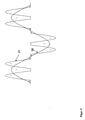
- FIG. 2 shows roughly schematically the operation of the invention.
- the input-side B6 bridge rectifier generates harmonics 21 in the network and relatively strongly deviating gradients from the sinusoidal 22. These harmonics 21 represent the current of the resistance welding system without any precautions.
- the active filter 15 with feed-in function and regenerative function according to the invention provides the areas marked with the plus sign and the minus sign as compensation currents for the operation of the welding converter.
- the areas marked with a plus sign are compensated by means of input currents (+) provided by the active filter 15.
- the regions marked with a minus sign are compensated for by means of decreasing currents provided by the active filter 15.
- the otherwise severely distorted input current of the resistance welding system is smoothed and closely approximates an ideal sinusoidal profile.
- the resulting advantages in terms of reduced ripple have been explained above.
Landscapes
- Engineering & Computer Science (AREA)
- Mechanical Engineering (AREA)
- Inverter Devices (AREA)
- Power Conversion In General (AREA)
- Supply And Distribution Of Alternating Current (AREA)
- Generation Of Surge Voltage And Current (AREA)
- Manufacturing Of Electrical Connectors (AREA)
- Details Of Resistors (AREA)
- Rectifiers (AREA)
Applications Claiming Priority (1)
| Application Number | Priority Date | Filing Date | Title |
|---|---|---|---|
| DE102012011246A DE102012011246A1 (de) | 2012-06-06 | 2012-06-06 | Verfahren zum Betrieb eines Schweissumrichters und Vorrichtung |
Publications (2)
| Publication Number | Publication Date |
|---|---|
| EP2671663A2 true EP2671663A2 (fr) | 2013-12-11 |
| EP2671663A3 EP2671663A3 (fr) | 2016-08-03 |
Family
ID=48049752
Family Applications (1)
| Application Number | Title | Priority Date | Filing Date |
|---|---|---|---|
| EP13001733.8A Withdrawn EP2671663A3 (fr) | 2012-06-06 | 2013-04-04 | Procédé de fonctionnement d'un dispositif de soudure par résistance ayant un filtre réseau; dispositif correspondant |
Country Status (3)
| Country | Link |
|---|---|
| US (1) | US9302342B2 (fr) |
| EP (1) | EP2671663A3 (fr) |
| DE (1) | DE102012011246A1 (fr) |
Families Citing this family (3)
| Publication number | Priority date | Publication date | Assignee | Title |
|---|---|---|---|---|
| EP3181284B1 (fr) * | 2015-12-17 | 2018-09-12 | Robert Bosch Gmbh | Circuit de convertisseur |
| US10464161B2 (en) * | 2016-09-26 | 2019-11-05 | Fronius International Gmbh | Power supply unit for a resistance welding apparatus |
| CN109202250A (zh) * | 2018-11-23 | 2019-01-15 | 合肥国声电子通信有限责任公司 | 一种智能焊接控制系统及方法 |
Citations (1)
| Publication number | Priority date | Publication date | Assignee | Title |
|---|---|---|---|---|
| DE4134461A1 (de) | 1991-10-18 | 1993-04-22 | Bosch Gmbh Robert | Verfahren und vorrichtung zur vermeidung uebergrosser stroeme in einem schweissumrichter |
Family Cites Families (6)
| Publication number | Priority date | Publication date | Assignee | Title |
|---|---|---|---|---|
| US4672298A (en) * | 1983-05-06 | 1987-06-09 | Frederick Rohatyn | Power factor correction system |
| FR2716045B1 (fr) * | 1994-02-04 | 1996-03-15 | Schlumberger Ind Sa | Filtre actif. |
| DE69515083T2 (de) * | 1994-05-27 | 2000-10-12 | Toshiba Kawasaki Kk | Steueranlage für Widerstandsschweissmaschine |
| DE19822130C1 (de) * | 1998-05-07 | 1999-10-28 | Manoharan Thamodharan | Verfahren zur Steuerung eines Lichtbogenschweißgeräts |
| ITPD980170A1 (it) * | 1998-07-07 | 2000-01-07 | Selco Srl | Generatore di saldatura con filtro attivo. |
| US8664564B2 (en) * | 2007-05-04 | 2014-03-04 | Illinois Tool Works Inc. | Controlled harmonics power supply for welding-type system |
-
2012
- 2012-06-06 DE DE102012011246A patent/DE102012011246A1/de not_active Withdrawn
-
2013
- 2013-04-04 EP EP13001733.8A patent/EP2671663A3/fr not_active Withdrawn
- 2013-06-05 US US13/910,671 patent/US9302342B2/en active Active
Patent Citations (1)
| Publication number | Priority date | Publication date | Assignee | Title |
|---|---|---|---|---|
| DE4134461A1 (de) | 1991-10-18 | 1993-04-22 | Bosch Gmbh Robert | Verfahren und vorrichtung zur vermeidung uebergrosser stroeme in einem schweissumrichter |
Also Published As
| Publication number | Publication date |
|---|---|
| US9302342B2 (en) | 2016-04-05 |
| EP2671663A3 (fr) | 2016-08-03 |
| US20130334178A1 (en) | 2013-12-19 |
| DE102012011246A1 (de) | 2013-12-12 |
Similar Documents
| Publication | Publication Date | Title |
|---|---|---|
| DE112010005612B4 (de) | Stromrichtervorrichtung | |
| DE102008018497B4 (de) | Wechselrichter, insbesondere Solarwechselrichter, mit einem aktven Netzfilter | |
| DE112013006680T5 (de) | Dreiphasen-Spannungs-Umsetzungsvorrichtung | |
| DE102005041927B4 (de) | Aktives Netzfilter | |
| EP2671663A2 (fr) | Procédé de fonctionnement d'un dispositif de soudure par résistance ayant un filtre réseau; dispositif correspondant | |
| DE10020635A1 (de) | Verfahren zur Blindleistungsregelung sowie Vorrichtung zur Erzeugung elektrischer Energie in einem elektrischen Netz | |
| EP2068416B1 (fr) | Précommande d'un convertisseur de source de tension | |
| DE102019119868C5 (de) | Verfahren zum Bestimmen eines Gleichrichterstufenausgangsstroms und/oder von netzseitigen Strömen eines Frequenzumrichters | |
| EP1708349A1 (fr) | Regulation de courant d'un convertisseur de tension connecté au réseau | |
| DE2217023C3 (de) | Speiseschaltung für einen von einer ein- oder mehrphasigen Wechselstromquelle gespeisten Gleichstromverbraucher | |
| AT409355B (de) | Verfahren und anordnung zum erzeugen von schweissstrom für eine widerstandsschweissmaschine | |
| DE2151019C3 (de) | Verfahren zur Regelung des einem Wechselstromnetz entnommenen oder zugeführten Stromes und Anordnung zur Durchführung des Verfahrens | |
| AT514654A1 (de) | Gleichrichterschaltung mit Strominjektion | |
| EP3402309A1 (fr) | Commande de puissance variable dans des dispositifs de chauffage auxiliaires électriques | |
| WO1998028095A1 (fr) | Dispositif de commande pour cage de laminoir | |
| EP3714539B1 (fr) | Convertisseur stable en court-circuit à commande de courant directe | |
| AT397321B (de) | Schaltungsanordnung bei einem gesteuerten stromrichter | |
| EP1142665B1 (fr) | Appareil de soudage à l'arc | |
| DE2433825C3 (de) | Vorrichtungen zur Energieversorgung und Verbesserung des Leistungsfaktors von Wechselstromnetzen | |
| DE686021C (de) | Einrichtung zur UEberlagerung von Wechselstromenergieverteilungsnetzen mit Schwachstroemen netzfremder Frequenz | |
| DE102017203664B4 (de) | Verfahren und Vorrichtung zur Bestimmung eines Stroms in einen Gleichrichter | |
| EP1079493B1 (fr) | Méthode pour la compensation des harmoniques dans des réseaux d'alimentation électrique | |
| WO2014198821A1 (fr) | Ensemble mutateur équipé d'un élément de commutation commun pour hacheur de freinage et convertisseur élévateur | |
| JP5703647B2 (ja) | 電力変換装置 | |
| WO2019242848A1 (fr) | Dispositif et procédé d'alimentation en courant continu |
Legal Events
| Date | Code | Title | Description |
|---|---|---|---|
| PUAI | Public reference made under article 153(3) epc to a published international application that has entered the european phase |
Free format text: ORIGINAL CODE: 0009012 |
|
| AK | Designated contracting states |
Kind code of ref document: A2 Designated state(s): AL AT BE BG CH CY CZ DE DK EE ES FI FR GB GR HR HU IE IS IT LI LT LU LV MC MK MT NL NO PL PT RO RS SE SI SK SM TR |
|
| AX | Request for extension of the european patent |
Extension state: BA ME |
|
| PUAL | Search report despatched |
Free format text: ORIGINAL CODE: 0009013 |
|
| AK | Designated contracting states |
Kind code of ref document: A3 Designated state(s): AL AT BE BG CH CY CZ DE DK EE ES FI FR GB GR HR HU IE IS IT LI LT LU LV MC MK MT NL NO PL PT RO RS SE SI SK SM TR |
|
| AX | Request for extension of the european patent |
Extension state: BA ME |
|
| RIC1 | Information provided on ipc code assigned before grant |
Ipc: B23K 11/24 20060101AFI20160627BHEP |
|
| STAA | Information on the status of an ep patent application or granted ep patent |
Free format text: STATUS: THE APPLICATION IS DEEMED TO BE WITHDRAWN |
|
| 18D | Application deemed to be withdrawn |
Effective date: 20170204 |