EP2671465B1 - Pain-free depilation head - Google Patents
Pain-free depilation head Download PDFInfo
- Publication number
- EP2671465B1 EP2671465B1 EP13169402.8A EP13169402A EP2671465B1 EP 2671465 B1 EP2671465 B1 EP 2671465B1 EP 13169402 A EP13169402 A EP 13169402A EP 2671465 B1 EP2671465 B1 EP 2671465B1
- Authority
- EP
- European Patent Office
- Prior art keywords
- depilatory
- cam
- appliance according
- axis
- skin
- Prior art date
- Legal status (The legal status is an assumption and is not a legal conclusion. Google has not performed a legal analysis and makes no representation as to the accuracy of the status listed.)
- Active
Links
Images


Classifications
-
- A—HUMAN NECESSITIES
- A45—HAND OR TRAVELLING ARTICLES
- A45D—HAIRDRESSING OR SHAVING EQUIPMENT; EQUIPMENT FOR COSMETICS OR COSMETIC TREATMENTS, e.g. FOR MANICURING OR PEDICURING
- A45D26/00—Hair-singeing apparatus; Apparatus for removing superfluous hair, e.g. tweezers
- A45D26/0023—Hair-singeing apparatus; Apparatus for removing superfluous hair, e.g. tweezers with rotating clamping elements
- A45D26/0028—Hair-singeing apparatus; Apparatus for removing superfluous hair, e.g. tweezers with rotating clamping elements with rotating discs or blades
-
- A—HUMAN NECESSITIES
- A45—HAND OR TRAVELLING ARTICLES
- A45D—HAIRDRESSING OR SHAVING EQUIPMENT; EQUIPMENT FOR COSMETICS OR COSMETIC TREATMENTS, e.g. FOR MANICURING OR PEDICURING
- A45D26/00—Hair-singeing apparatus; Apparatus for removing superfluous hair, e.g. tweezers
- A45D26/0061—Hair-singeing apparatus; Apparatus for removing superfluous hair, e.g. tweezers with means for reducing pain during hair removal
-
- A—HUMAN NECESSITIES
- A45—HAND OR TRAVELLING ARTICLES
- A45D—HAIRDRESSING OR SHAVING EQUIPMENT; EQUIPMENT FOR COSMETICS OR COSMETIC TREATMENTS, e.g. FOR MANICURING OR PEDICURING
- A45D26/00—Hair-singeing apparatus; Apparatus for removing superfluous hair, e.g. tweezers
- A45D2026/008—Details of apparatus for removing superfluous hair
- A45D2026/0095—Details of apparatus for removing superfluous hair with additional cutting head, e.g. interchangeable
Definitions
- the present invention relates to the field of tweezers of the type comprising a rotary cylinder with tongs for tearing unwanted hair from the human body, and more particularly relates to an epilator comprising a massage means producing an anti-pain effect.
- a plucking tweezers generally comprise blade or disc grippers disposed on a rotating barrel, the pliers being caused to close and open periodically to grip and tighten the bristles close to the barrel. the skin to tear them by the rotation of the cylinder and then to evacuate the torn hairs before starting a new cycle of tearing. Pulling the hair is a very effective method against their regrowth, but it often causes significant pain.
- Another document EP1782709 in the name of the applicant describes a depilatory device comprising a depilatory head removable and interchangeable with a cutting head.
- the cutting head comprises a fixed blade and a movable blade, the movable blade being driven in translation by a vibrating element in a direction parallel to the axis of the hair removal roller.
- the element vibrator is fixed relative to the housing of the device and it is driven by a cam recovering the movement of the electric motor by a gear train, the cam itself being also fixed relative to the housing.
- This document discloses a razor adjacent to an anti-pain means driven by a cam that can directly transmit the movement of the motor in a displacement in translation.
- the prior art does not propose the combination of an epilation means and an effective pain-relieving means, the two functions being realized simultaneously and being implemented in a compact block to be fixed on a personal care device. multifunction skin.
- the object of the invention is to overcome the aforementioned drawbacks and to provide a multifunctional body care device compatible with different interchangeable skin treatment blocks, at least one block comprises a depilation means provided with an effective pain-killing means .
- Another object of the invention is to provide a depilatory device with anti-pain medium compact and robust.
- Another object of the invention is a depilatory device provided with an anti-pain means easy to clean in case of jamming torn hairs.
- Another object of the invention is an effective and ergonomic depilatory device, for tearing the hair always closer to the skin for a better hair removal result.
- Another object of the invention is to provide an anti-pain means of rubbing the skin used during epilation which is effective.
- Another object of the invention is to provide a depilatory device provided with an easy-to-use pain-relieving means having an improved lifetime while ensuring effective training of its moving parts.
- Another object of the invention is a depilatory device for performing a massage on the skin to be epilated having an oscillation frequency adapted for an optimal anti-pain effect.
- Yet another object of the invention is an anti-pain depilatory device which guarantees safety for the user.
- Another object of the invention is to provide an epilator having a reliable anti-pain means, of simple construction and which lends itself to mass production, for less manufacturing costs.
- rotary depilating cylinder any device capable of supporting and driving the tweezers in a continuous rotational movement about at least one axis of rotation.
- a device may be in particular a rotary roller clamps, but also a belt carrying clamps, a chain driving articulated modules carrying tweezers, etc..
- This movement in the plane of the skin produces in particular a rubbing massage action performed just next to the action zone of the hair removal roller and therefore in an area adjacent to the hair removal zone.
- rubbing a pain-sensitized area vigorously with pain has the effect of immediately relieving pain.
- this massage has an anesthetic effect over a short time interval, and that the pain due to hair removal becomes more bearable thereafter .
- the active massaging element is integrated in the bi-treatment block which at the same time contains the depilating cylinder, the massage function for an anti-pain effect is always performed simultaneously with the pulling of the hairs.
- the housing is constructed so as to receive other treatment heads interchangeable with the bi-treatment block, these other functional heads do not require motorized painter means as the hair removal function requires.
- the presence of the support heel unequivocally indicates the direction of use of the epilating head in that the heel must be placed upstream of the epilation window relative to the direction of movement of the epilation head. on the area to be depilated.
- the heel and its contact surface allow a slight tensioning of the skin of the area to be depilated due to the friction and the slight traction induced by the heel and its contact surface during the displacement of the head. hair removal against the skin of the area to be depilated.
- the rotation, along an axis parallel to and coincident with the axis of rotation of the hair removal roller, the movable flap and the heel it carries keeps contact with the skin of the area to be epilated when slight variations in the orientation of the casing with respect to the skin of the zone to be dehaired, induced by the user.
- the heel and its contact surface are always parallel to the skin of the area to be depilated so that the slight tension of the latter is still maintained despite the slight variations in orientation of the housing.
- the massaging element is integrated with the hair removal roller in the same bi-treatment block via the movable flap. This also allows tensioning of the skin so that it can pinch the hair without increasing the sensation of pain. Indeed, thanks to the movable flap, the massaging element is always maintained at a bearing position on the skin despite variations in orientation of the bi-treatment block for a massage with optimal anti-pain effect.
- the depilating cylinder comprises means for defining the angular sectors and the movable flap is secured to said means for defining the angular sectors so as to ensure a modification of the position of the angular sectors relative to the bi-treatment block according to the orientation of the mobile component.
- the sequence of opening and closing clamps is always optimal despite variations in the inclination of the housing relative to the skin of the area to be dehaired.
- the apparatus comprises a rotary cam about a secondary axis parallel to the epilation axis, the cam being mounted on a rod and intended to drive said massaging element. It is a grooved cam for the purpose of transforming a rotational movement into a translational movement of the massaging element. It simplifies significantly the construction of both the accessory and the device without increasing the size of the case, while obtaining a more compact device, with a greatly increased speed, easy to implement, effective in term training and an extended life.
- said rod is integral with the movable flap.
- the cam is integrated in the dual-processing block and disassembles with the latter simultaneously, which allows a saving of space of the device.
- the cam comprises at one of its ends a cam gear, the cam is intended to be driven by the depilating cylinder by means of a translation gear train.
- the cam comprises a groove formed to allow rotation of the cam in two opposite directions. This makes it possible to double the oscillation speed of the massaging element and to ensure safety for the user. Because the cam can rotate in the opposite direction to the operation of the device, the user will be able to handle in case of trapping of hair to clean the block bi-treatment.
- the cam path is defined such that during rotation of said cam, it enables the oscillation speed of the massaging element to be doubled and to ensure safety for the user.
- the rod is secured to the housing.
- the cam is integrated in the housing of the apparatus.
- the bi-processing block comprises at least one actuating arm of the massaging element perpendicular to the axis ⁇ intended to be driven by the motor by means of a mechanical transmission.
- said mechanical transmission comprises at least said cam gear, a motor gear and a vibrating element intended to be oscillated by the cam, said vibrating element comprising a housing for receiving said actuating arm and guiding it in translation in a direction parallel to the hair removal axis.
- the massaging element is connected to an actuating arm which has a certain degree of freedom in a housing of the vibrating element and which is driven by the latter for a back and forth movement.
- the vibrating element having a T shape moves in the groove of the cam to ensure the translational movement.
- the massaging element can therefore follow the movement of the movable flap by sizing the housing of the vibrating element.
- the massaging member is a bar having a substantially planar skin contacting surface.
- a surface having a relatively high roughness so that it produces a rubbing massage effect or an exfoliating effect during hair removal.
- the massaging element is a bar having a skin contacting surface comprising protuberances.
- massage nubs or half spheres protruding from the plane of the contact surface with the skin of the bar being able to penetrate the skin, each pin / half sphere constituting in fact an anchoring point which causes the skin on the move to increase the effect of massage into deeper layers of the skin.
- the bar is ZAMAK which has a low coefficient of friction property.
- Zamak is an alloy of zinc, aluminum and magnesium and sometimes copper. Its name is an acronym for the German names of the metals that compose it: Zink (zinc), Aluminum, Magnesium (magnesium) and Kupfer (copper).
- the material chosen for the bar is a material hard enough not to adhere to the skin and drag it during the friction exerted on the latter by the bar moving.
- a material may be alternatively, for example, a plastic material of the polyamide type loaded with glass ball or POM which is a material known to have a low coefficient of friction due to its good sliding properties.
- a body care device that includes at least one massage head mounted interchangeably on the housing. Because the bi-treatment block is held on the housing by a reversible attachment means, it is detachable and interchangeable with other care accessories. We can imagine accessories such as a massage head, a shaving head, or a mower head, etc.
- the apparatus may comprise an airflow system having a fan driven by an electric motor to create an air flow between an inlet opening of the housing and an outlet opening of the housing as defined in the patent.
- EP1884174 of the Applicant cited here for reference. This helps bring a feeling of freshness to relieve heated skin due to hair removal and increase the effectiveness of painkiller.
- a single motor can be used for the airflow system as well as for hair removal in order to save cost and compactness.
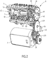
- a body care appliance as illustrated in the Figure 1 and designated as a whole by the reference 1 comprises a housing 2 defining a gripping area and being equipped with a control button 6 for starting or stopping the apparatus.
- the housing 2 has a hollow shape in which is arranged an electric motor 3 as visible in the Figure 2 which drives a gear train 22 which transmits the rotational movement of a motor gear 33 to a gear wheel 221 by means of a gear intermediary 223.
- the transmission wheel 221 comes into direct contact with a drive pinion 42 of an epilation cylinder 4.
- Such a depilating cylinder 4 comprises several tearing modules consisting of clamps or rotating discs for exerting a rapid closure for pinching the bristles.
- the hair removal cylinder 4 is rotatable relative to a hair removal axis ⁇ parallel to the plane of the skin to be depilated and is rotated by the drive pinion 42.
- the hair removal cylinder comprises means for defining the sectors angular 41, for example, formed by one or more cams associated with cam paths adapted so that the clamps are open when they begin to flush at a window epilation 92 and close while they out flush again and well before exiting the hair removal window 92.
- the apparatus provided with the depilating cylinder 4 comprises in the vicinity thereof a massing element 7 in the form of a bar designed to oscillate at a high frequency in a direction parallel to the epilation axis ⁇ .
- a massing element 7 in the form of a bar designed to oscillate at a high frequency in a direction parallel to the epilation axis ⁇ .
- Such a movement of the bar is intended to accompany the mechanical depilation causing pain due to tearing of the hair and provide an anesthetic effect that can "scramble" the sensation of pain.
- the depilating cylinder 4 and the massaging element 7 are integrated in the same bi-treatment block designated by the reference 8 .
- the bi-processing block 8 comprises a base 82 integral with a cover 83 which receives the depilating cylinder 4; the massaging element 7 and their drive mechanism.
- the base 82 comprises in the lower part of the hooks 25 coming automatically, under the pressure of a spring, in engagement with locking means 222 located in the upper part of the housing 2.
- An unlocking button 24 is provided on one side of the housing 2 by means of which the locking means 222 are pushed to release the hooks 25 and remove the bi-processing block 8.
- the bar is incorporated in a movable flap 9 which is itself housed in the cover 83 of the block.
- the hair removal cylinder 4 is flush with the epilation window 92 provided in the body of the bi-treatment block.
- the epilation window 92 is defined by, on the one hand, two longitudinal edges 91 and 94 parallel to each other and to the epilation axis ⁇ and, on the other hand, two transverse edges which are parallel to each other and have an arcuate shape being contained in planes perpendicular to the axis of rotation ⁇ .
- One of the longitudinal edges, here the lower edge 94 is fixed being formed by an edge of the cover 83.
- the other longitudinal edge is movable by being formed by the movable flap 9 in rotation around the hair removal axis ⁇ .
- This movable longitudinal edge is designated by the reference 91.
- the movable flap 9 comprises a bearing heel 93 which extends in the extension of the movable longitudinal edge 91 opposite the epilation window 92. The heel then defines a contact surface with the skin of the area to be depilated.
- the movable flap 9 is preferably secured to the means for defining the angular sectors 41.
- the means for defining the angular sectors 41 are rotatable about the depilation axis ⁇ and follow the variations of the inclination of the housing 2 relative to the skin of the area to be dehaired.
- the movable flap 9 further comprises a massage window 95 giving access to the massaging element 7.
- the latter comprises a circular groove 73 forming with protruding lines of the massage window 95 a slide connection, which ensures the movement back and forth of the bar in a plane parallel to that of the shutter mobile 9.
- the bar follows the movement of the movable flap 9 regardless of the inclination of the device and ensures an optimal massage effect. Note that, under the frictional force between the movable flap 9 and the drive pinion 42 of the depilating cylinder 4, the movable flap 9 and the barrette painter will always be required to solicit the skin and thus kept in contact intimate with the skin.
- the bar is driven directly by a cam 5.
- the transmission wheel 221 transmits the rotational movement to the cam 5 by means of a translational gear train 81 comprising, in order, a cam gear 52, a the gear wheel 60 and the drive gear 42 of the depilating cylinder 4.
- the drive pinion 42 is rotated by the transmission wheel 221 and drives, at the same time, the speed gear 60.
- the speed gear 60 being an intermediate gear transmits the movement to the cam gear 52 whose transmitted speed is greater than that of the drive gear 42 because the speed gear 60 has a larger diameter. small as the drive pinion 42.
- the cam 5 being mounted coaxially with the cam gear 52 on a rod 53 secured to the movable flap 9 is rotated about a secondary axis ⁇ 'parallel to the axis d ⁇ hair removal.
- the cam 5 In order to be able to transmit the rotational movement of the cam 5 in a translational movement of the massaging element 7, the cam 5 has a groove 51 into which a cylinder 71 projecting from the massaging element 7 is inserted. cylinder 71 being guided by the ramp of the groove 51 to bring the bar to a movement back and forth.
- the advantage of such a drive system is to be able to modulate the speed of the cam 5 so that it is adapted to the frequency of friction of the bar on the skin.
- the sprockets forming part of the translation gear train 81 have diameters and numbers of teeth at a certain ratio, which makes it possible to amplify or reduce the output speed of the housing by modifying these parameters.
- this first embodiment it is possible to eliminate the speed gear 60 while putting the cam gear 52 in direct contact with the drive gear 42. In this case, it is possible to gain in terms of space of the bi-treatment block. However, this variant is not preferable since a collision occurs between the teeth of the drive gear 42 and the movable flap 9 when the cam gear 52 is too close to the depilating roller 4.
- the cam 5 is preferably a double cam having a groove for moving the bar in one direction or the other. This has the advantage of being able to double the frequency of vibration of the bar and also to ensure the safety and efficiency of the device.
- the double cam allows to manually turn the hair removal cylinder in the opposite direction to that Operation for troubleshooting or cleaning.
- the cam 5 is rotated by the gear train 22 forming part of the assembly of a mechanical transmission 23 located inside the housing 2.
- the cam 5 is driven by the cam gear 52 which itself is set in motion by one of the pinions of the gear train 22, for example, the transmission wheel 221.
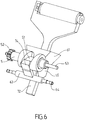
- a vibrating element 61 forming part of the mechanical transmission 23 connects the cam 5 and the element massaging 7 in order to transmit the movement of the cam 5 remaining in the housing 2 to the removable massaging element 7 of the housing 2 and separable from the cam 5.
- the vibrating element 61 is a cross-shaped piece comprising a horizontal branch 63 mounted on a horizontal rod 64 for ensuring the translational guidance of the vibrating element 61 and a hollow branch 65 having a housing 62 in which comes insert the object to be activated.
- the horizontal branch 63 comprises a protruding guide pin 74 which is inserted into the groove 51 of the cam 5 to be guided in translation by the ramps of the groove 51 and follow the movement of the cam 5.
- the bar comprises an actuating arm 72 in the form of two metal rods intended to fit into the housing 62 and to be guided by the walls of the housing 62. Knowing that the housing 62 can be opening all keeping the same degree of freedom for the movement of the actuating arm. With such a construction of the apparatus, the vibration frequency of the bar is controlled and optimized and the cam gear 52 can be rotated at a speed greater than that of the transmission wheel 221.
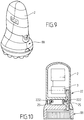
- the housing 2 of the apparatus is adapted to receive a massage head as shown in FIG. Figure 9 .
- the device comprises on the opposite side of the bar an air outlet which blows fresh air to the skin depilated.
- the system comprises a propeller driven by an electric motor to create an air flow between an inlet opening of the housing 87 and an outlet opening of the casing 86 as defined in the patent EP1884174 of the Applicant, cited here for reference. This helps bring a feeling of freshness to relieve heated skin during hair removal and increase the effectiveness of painkillers.
Description
La présente invention concerne le domaine des appareils à épiler du type comportant un cylindre rotatif à pinces destinées à arracher les poils non désirés du corps humain, et elle concerne plus particulièrement un épilateur comprenant un moyen de massage produisant un effet anti douleur.The present invention relates to the field of tweezers of the type comprising a rotary cylinder with tongs for tearing unwanted hair from the human body, and more particularly relates to an epilator comprising a massage means producing an anti-pain effect.
Un appareil à épiler à pinces d'arrachage comporte en général des pinces sous forme de lames ou de disques disposés sur un cylindre rotatif, les pinces étant amenées à se fermer et s'ouvrir périodiquement de manière à saisir et serrer les poils à proximité de la peau pour les arracher par la rotation du cylindre et ensuite à évacuer les poils arrachés avant de recommencer un nouveau cycle d'arrachage. L'arrachage des poils s'avère une méthode très efficace contre leur repousse, mais il engendre souvent une douleur non négligeable.A plucking tweezers generally comprise blade or disc grippers disposed on a rotating barrel, the pliers being caused to close and open periodically to grip and tighten the bristles close to the barrel. the skin to tear them by the rotation of the cylinder and then to evacuate the torn hairs before starting a new cycle of tearing. Pulling the hair is a very effective method against their regrowth, but it often causes significant pain.
Une telle fonction anti douleur sur un appareil à épiler a été présentée dans le document
Un autre document
Le but de l'invention est de remédier aux inconvénients susmentionnés et de proposer un appareil de soin corporel multifonctions compatible avec différents blocs de traitement de la peau interchangeables, dont au moins un bloc comprend un moyen d'épilation muni d'un moyen antidouleur efficace.The object of the invention is to overcome the aforementioned drawbacks and to provide a multifunctional body care device compatible with different interchangeable skin treatment blocks, at least one block comprises a depilation means provided with an effective pain-killing means .
Un autre but de l'invention est de fournir un appareil à épiler au moyen anti douleur compact et robuste.Another object of the invention is to provide a depilatory device with anti-pain medium compact and robust.
Un autre but de l'invention est un appareil à épiler muni d'un moyen anti douleur facile à nettoyer en cas de coincement des poils arrachés.Another object of the invention is a depilatory device provided with an anti-pain means easy to clean in case of jamming torn hairs.
Un autre but de l'invention est un appareil à épiler efficace et ergonomique, permettant d'arracher les poils toujours au plus près de la peau pour un meilleur résultat d'épilation.Another object of the invention is an effective and ergonomic depilatory device, for tearing the hair always closer to the skin for a better hair removal result.
Un autre but de l'invention est de fournir un moyen anti douleur de frottement de la peau utilisé pendant l'épilation qui est efficace.Another object of the invention is to provide an anti-pain means of rubbing the skin used during epilation which is effective.
Un autre but de l'invention est de fournir un appareil à épiler muni d'un moyen anti douleur facile à mettre en place, ayant une durée de vie améliorée tout en assurant un entrainement efficace de ses parties mobiles.Another object of the invention is to provide a depilatory device provided with an easy-to-use pain-relieving means having an improved lifetime while ensuring effective training of its moving parts.
Un autre but de l'invention est un appareil à épiler permettant d'effectuer un massage sur la peau à épiler ayant une fréquence d'oscillation adaptée pour un effet anti douleur optimal.Another object of the invention is a depilatory device for performing a massage on the skin to be epilated having an oscillation frequency adapted for an optimal anti-pain effect.
Encore un autre but de l'invention est un appareil à épiler au moyen anti douleur qui garantit une sécurité pour l'utilisateur.Yet another object of the invention is an anti-pain depilatory device which guarantees safety for the user.
Un autre but de l'invention et de fournir un épilateur ayant un moyen anti douleur fiable, de construction simple et qui se prête à une fabrication en grande série, pour des coûts de fabrication moindres.Another object of the invention is to provide an epilator having a reliable anti-pain means, of simple construction and which lends itself to mass production, for less manufacturing costs.
Ces buts sont atteints avec un appareil de soin corporel tel que divulgué dans la revendication 1.These objects are achieved with a body care apparatus as disclosed in
Par cylindre d'épilation rotatif on comprend tout dispositif capable de supporter et d'entraîner les pinces à épiler en un mouvement continu de rotation autour d'au moins un axe de rotation. Un tel dispositif peut être notamment un rouleau rotatif à pinces, mais également une courroie portant des pinces, une chaîne entraînant des modules articulée portant des pinces à épiler, etc.By rotary depilating cylinder is meant any device capable of supporting and driving the tweezers in a continuous rotational movement about at least one axis of rotation. Such a device may be in particular a rotary roller clamps, but also a belt carrying clamps, a chain driving articulated modules carrying tweezers, etc..
Ce déplacement dans le plan de la peau produit notamment une action de massage par frottement effectuée juste à côté de la zone d'action du rouleau d'épilation et donc dans une zone adjacente à la zone d'épilation. Lors des tests effectués sur diverses personnes, on a constaté que le fait de masser vigoureusement par frottement une zone sensibilisée par la douleur a pour effet de calmer immédiatement la douleur. On a également constaté qu'en massant une zone de peau avant ou pendant une action d'arrachage des poils, ce massage a un effet anesthésiant sur un court intervalle temporel, et que la douleur due à l'épilation devient plus supportable par la suite.This movement in the plane of the skin produces in particular a rubbing massage action performed just next to the action zone of the hair removal roller and therefore in an area adjacent to the hair removal zone. In tests on various individuals, it has been found that rubbing a pain-sensitized area vigorously with pain has the effect of immediately relieving pain. It has also been found that by massaging an area of skin before or during a pulling action of the bristles, this massage has an anesthetic effect over a short time interval, and that the pain due to hair removal becomes more bearable thereafter .
De surcroit, on constate une action bénéfique du massage en surface de la peau sur la microcirculation sanguine ayant comme effet l'atténuation, avec le frottement, de la présence des points rouges provoqués par l'arrachage des poils.In addition, there is a beneficial action of the surface massage of the skin on the blood microcirculation having the effect of attenuation, with friction, the presence of red dots caused by tearing of the hair.
Du fait que l'élément massant actif est intégré dans le bloc bi-traitement qui contient en même temps le cylindre d'épilation, la fonction massage pour un effet anti douleur est toujours réalisée simultanément à l'arrachage des poils. Surtout, grâce à une fixation réversible de l'ensemble du bloc bi-traitement, ce dernier peut se démonter facilement du boîtier quand l'utilisateur souhaite un traitement autre que l'épilation. A cet effet, le boîtier est construit de façon à pouvoir recevoir d'autres têtes de traitement interchangeables avec le bloc bi-traitement, ces autres têtes fonctionnelles ne nécessitant pas de moyen antidouleur motorisé comme la fonction épilation le nécessite.Because the active massaging element is integrated in the bi-treatment block which at the same time contains the depilating cylinder, the massage function for an anti-pain effect is always performed simultaneously with the pulling of the hairs. Above all, thanks to a reversible fixation of the entire bi-treatment block, the latter can be dismounted easily from the housing when the user wants a treatment other than hair removal. For this purpose, the housing is constructed so as to receive other treatment heads interchangeable with the bi-treatment block, these other functional heads do not require motorized painter means as the hair removal function requires.
La présence du talon d'appui indique sans équivoque le sens d'utilisation de la tête d'épilation dans la mesure où le talon doit être placé en amont de la fenêtre d'épilation par rapport au sens de déplacement de la tête d'épilation sur la zone à épiler. De plus, le talon et sa surface de contact permettent une légère mise en tension de la peau de la zone à épiler en raison du frottement et de la légère traction induite par le talon et sa surface de contact lors du déplacement de la tête d'épilation contre la peau de la zone à épiler. Il doit être remarqué que la rotation, selon un axe parallèle et confondu avec l'axe de rotation du rouleau d'épilation ,du volet mobile et du talon qu'il porte permet de conserver le contact avec la peau de la zone à épiler lors des légères variations, de l'orientation du boîtier par rapport à la peau de la zone à épiler, induites par l'utilisateur. Ainsi, le talon et sa surface de contact restent toujours parallèles à la peau de la zone à épiler de sorte que la légère tension de cette dernière est toujours maintenue malgré les légères variations d'orientation du boîtier.The presence of the support heel unequivocally indicates the direction of use of the epilating head in that the heel must be placed upstream of the epilation window relative to the direction of movement of the epilation head. on the area to be depilated. In addition, the heel and its contact surface allow a slight tensioning of the skin of the area to be depilated due to the friction and the slight traction induced by the heel and its contact surface during the displacement of the head. hair removal against the skin of the area to be depilated. It should be noted that the rotation, along an axis parallel to and coincident with the axis of rotation of the hair removal roller, the movable flap and the heel it carries keeps contact with the skin of the area to be epilated when slight variations in the orientation of the casing with respect to the skin of the zone to be dehaired, induced by the user. Thus, the heel and its contact surface are always parallel to the skin of the area to be depilated so that the slight tension of the latter is still maintained despite the slight variations in orientation of the housing.
L'élément massant est intégré avec le rouleau d'épilation dans le même bloc bi-traitement par le biais du volet mobile. Ceci permet également une mise en tension de la peau afin de pouvoir bien pincer les poils sans pour autant augmenter la sensation de douleur. En effet, grâce au volet mobile, l'élément massant est toujours maintenu à une position d'appui sur la peau malgré les variations d'orientation du bloc bi-traitement pour un massage à effet anti douleur optimal.The massaging element is integrated with the hair removal roller in the same bi-treatment block via the movable flap. This also allows tensioning of the skin so that it can pinch the hair without increasing the sensation of pain. Indeed, thanks to the movable flap, the massaging element is always maintained at a bearing position on the skin despite variations in orientation of the bi-treatment block for a massage with optimal anti-pain effect.
De surcroît, le cylindre d'épilation comprend des moyens de définition des secteurs angulaires et le volet mobile est solidaire desdits moyens de définition des secteurs angulaires de manière à assurer une modification de la position des secteurs angulaires par rapport au bloc bi-traitement en fonction de l'orientation du volet mobile. Ainsi, le déroulement des séquences d'ouverture et de fermeture des pinces est toujours optimal malgré les variations de l'inclinaison du boîtier par rapport à la peau de la zone à épiler.In addition, the depilating cylinder comprises means for defining the angular sectors and the movable flap is secured to said means for defining the angular sectors so as to ensure a modification of the position of the angular sectors relative to the bi-treatment block according to the orientation of the mobile component. Thus, the sequence of opening and closing clamps is always optimal despite variations in the inclination of the housing relative to the skin of the area to be dehaired.
Selon l'invention, l'appareil comprend une came rotative autour d'un axe secondaire parallèle à l'axe d'épilation, la came étant montée sur une tige et destinée à entrainer ledit élément massant. Il s'agit d'une came à rainure ayant pour but de transformer un mouvement de rotation en un mouvement de translation, de l'élément massant. On simplifie nettement la construction à la fois de l'accessoire et de l'appareil sans augmenter pour autant l'encombrement du boitier, tout en obtenant un dispositif plus compact, avec une vitesse fortement augmentée, facile à mettre en place, efficace en terme d'entrainement et d'une durée de vie prolongée.According to the invention, the apparatus comprises a rotary cam about a secondary axis parallel to the epilation axis, the cam being mounted on a rod and intended to drive said massaging element. It is a grooved cam for the purpose of transforming a rotational movement into a translational movement of the massaging element. It simplifies significantly the construction of both the accessory and the device without increasing the size of the case, while obtaining a more compact device, with a greatly increased speed, easy to implement, effective in term training and an extended life.
Dans une première variante, ladite tige est solidaire au volet mobile. Ainsi, la came est intégrée au bloc bi-traitement et se démonte avec ce dernier de façon simultanée, ce qui permet un gain d'encombrement de l'appareil.In a first variant, said rod is integral with the movable flap. Thus, the cam is integrated in the dual-processing block and disassembles with the latter simultaneously, which allows a saving of space of the device.
Avantageusement, la came comprend à une de ses extrémités un pignon de came, la came est destinée à être entrainée par le cylindre d'épilation au moyen d'un train d'engrenage translation.Advantageously, the cam comprises at one of its ends a cam gear, the cam is intended to be driven by the depilating cylinder by means of a translation gear train.
On aurait pu imaginer un pignon de came prenant contact directement avec le pignon d'entrainement du rouleau d'épilation afin d'être entrainé par celui-ci, ce qui permet de réduire l'encombrement du bloc bi-traitement. On préfère toutefois une structure où ledit train d'engrenage translation comprend ledit pignon de came, le pignon d'entrainement et au moins un pignon de vitesse entre les deux pour des raisons de sécurité et de réglage. Avec ce pignon intermédiaire, il devient possible d'augmenter encore la vitesse d'oscillation de l'élément massant. L'ajout du pignon de vitesse présente un avantage de sécurité dans la mesure où une collision se produit entre les dents du pignon d'entrainement et le cadre quand le pignon de came est trop près du rouleau.One could have imagined a cam gear contacting directly with the drive pinion of the depilating roller to be driven by it, which reduces the size of the block bi-treatment. However, a structure is preferred in which said translational gear train comprises said cam gear, the drive gear and at least one gear wheel between the two for reasons of safety and adjustment. With this intermediate gear, it becomes possible to further increase the oscillation speed of the massaging element. The addition of the sprocket has a safety benefit in that a collision occurs between the sprocket teeth and the frame when the sprocket is too close to the roller.
De préférence, la came comprend une rainure formée pour permettre une rotation de la came dans les deux sens opposés. Ceci permet de doubler la vitesse d'oscillation de l'élément massant et d'assurer une sécurité pour l'utilisateur. Du fait que la came puisse tourner dans le sens opposé à celui du fonctionnement de l'appareil, l'utilisateur aura la possibilité de manipuler en cas de coincement de poils afin de nettoyer le bloc bi-traitement. Le chemin de came est défini de telle manière qu'il permet lors d'une rotation de ladite came de doubler la vitesse d'oscillation de l'élément massant et d'assurer une sécurité pour l'utilisateur.Preferably, the cam comprises a groove formed to allow rotation of the cam in two opposite directions. This makes it possible to double the oscillation speed of the massaging element and to ensure safety for the user. Because the cam can rotate in the opposite direction to the operation of the device, the user will be able to handle in case of trapping of hair to clean the block bi-treatment. The cam path is defined such that during rotation of said cam, it enables the oscillation speed of the massaging element to be doubled and to ensure safety for the user.
Dans une deuxième variante, la tige est solidaire du boitier. Ainsi, la came est intégrée au boîtier de l'appareil.In a second variant, the rod is secured to the housing. Thus, the cam is integrated in the housing of the apparatus.
Dans cette deuxième variante, le bloc bi-traitement comprend au moins un bras d'actionnement de l'élément massant perpendiculaire à l'axe Δ destiné à être entrainé par le moteur au moyen d'une transmission mécanique.In this second variant, the bi-processing block comprises at least one actuating arm of the massaging element perpendicular to the axis Δ intended to be driven by the motor by means of a mechanical transmission.
Avantageusement, ladite transmission mécanique comprend au moins ledit pignon de came, un pignon de moteur et un élément vibrant destiné à être oscillé par la came, ledit élément vibrant comprenant un logement destiné à recevoir ledit bras d'actionnement et le guider en translation dans une direction parallèle à l'axe d'épilation. Selon ce mode de réalisation, l'élément massant est relié à un bras d'actionnement qui a un certain degré de liberté dans un logement de l'élément vibrant et qui est entrainé par ce dernier pour un mouvement de va -et - vient. L'élément vibrant ayant une forme en T se déplace dans la rainure de la came pour assurer le mouvement en translation. L'élément massant peut donc suivre le mouvement du volet mobile grâce au dimensionnement du logement de l'élément vibrant.Advantageously, said mechanical transmission comprises at least said cam gear, a motor gear and a vibrating element intended to be oscillated by the cam, said vibrating element comprising a housing for receiving said actuating arm and guiding it in translation in a direction parallel to the hair removal axis. According to this embodiment, the massaging element is connected to an actuating arm which has a certain degree of freedom in a housing of the vibrating element and which is driven by the latter for a back and forth movement. The vibrating element having a T shape moves in the groove of the cam to ensure the translational movement. The massaging element can therefore follow the movement of the movable flap by sizing the housing of the vibrating element.
Selon une alternative, l'élément massant est une barrette ayant une surface de contact avec la peau substantiellement plane. On peut imaginer une surface présentant une rugosité relativement importante pour qu'elle produise un effet de massage par frottement ou encore un effet exfoliant pendant l'épilation. On peut aussi se permettre d'utiliser une surface lisse mais avec un coefficient de friction variable suivant le besoin de l'utilisateur pour tirer plus ou moins la couche épidermique de la peau pour un massage doux.Alternatively, the massaging member is a bar having a substantially planar skin contacting surface. One can imagine a surface having a relatively high roughness so that it produces a rubbing massage effect or an exfoliating effect during hair removal. We can also afford to use a smooth surface but with a coefficient of friction variable according to the need of the user to draw more or less the epidermal layer of the skin for a gentle massage.
Selon une autre alternative, l'élément massant est une barrette ayant une surface de contact avec la peau comprenant des protubérances. Par exemple des picots de massage ou des demi sphères faisant saillie par rapport au plan de la surface de contact avec la peau de la barrette pouvant pénétrer dans la peau, chaque picot/demi sphère constituant en effet un point d'ancrage qui entraîne la peau en déplacement afin d'augmenter l'effet de massage jusque dans des couches plus profondes de la peau.According to another alternative, the massaging element is a bar having a skin contacting surface comprising protuberances. For example massage nubs or half spheres protruding from the plane of the contact surface with the skin of the bar being able to penetrate the skin, each pin / half sphere constituting in fact an anchoring point which causes the skin on the move to increase the effect of massage into deeper layers of the skin.
De préférence, la barrette est en ZAMAK qui a une propriété de faible coefficient de frottement. Le zamak est un alliage de zinc, d'aluminium et de magnésium et parfois de cuivre. Son nom est un acronyme des noms allemands des métaux qui le composent :Zink (zinc), Aluminium, Magnésium (magnésium) et Kupfer (cuivre).Preferably, the bar is ZAMAK which has a low coefficient of friction property. Zamak is an alloy of zinc, aluminum and magnesium and sometimes copper. Its name is an acronym for the German names of the metals that compose it: Zink (zinc), Aluminum, Magnesium (magnesium) and Kupfer (copper).
Il faut préciser que le matériau choisi pour la barrette est un matériau suffisamment dur pour ne pas adhérer à la peau et l'entrainer lors du frottement exercé sur cette dernière par la barrette en mouvement. Un tel matériau peut être alternativement, à titre exemple, un matériau plastique du type polyamide chargé en bille de verre ou du POM qui est un matériau connu pour avoir un faible coefficient de frottement dû à ses bonnes propriétés de glissement.It should be noted that the material chosen for the bar is a material hard enough not to adhere to the skin and drag it during the friction exerted on the latter by the bar moving. Such a material may be alternatively, for example, a plastic material of the polyamide type loaded with glass ball or POM which is a material known to have a low coefficient of friction due to its good sliding properties.
De surcroît, on peut également envisager un appareil de soins corporels qui comprend au moins une tête de massage monté interchangeable sur le boitier. Du fait que le bloc bi-traitement est maintenu sur le boitier par un moyen de fixation réversible, il est détachable et interchangeable avec d'autres accessoires de soin. On peut imaginer des accessoires tels qu'une tête de massage, une tête de rasage, ou encore une tête de tondeuse etc.In addition, one can also consider a body care device that includes at least one massage head mounted interchangeably on the housing. Because the bi-treatment block is held on the housing by a reversible attachment means, it is detachable and interchangeable with other care accessories. We can imagine accessories such as a massage head, a shaving head, or a mower head, etc.
Enfin, l'appareil peut comprendre un système de flux d'air ayant un ventilateur entrainé par un moteur électrique pour créer un flux d'air entre une ouverture d'entrée du boitier et une ouverture de sortie du boitier tel que défini dans le brevet
L'invention sera mieux comprise à l'étude des modes de réalisation pris à titre nullement limitatif et illustrés dans les figures annexées dans lesquelles :
- La
Figure 1 est une vue en perspective de l'ensemble de l'appareil de soin corporel; - La
Figure 2 est une vue en perspective de la construction intérieure du bloc bi-traitement ainsi que son train d'engrenage selon la première variante de l'invention; - La
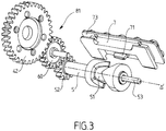
Figure 3 est une vue éclatée de l'élément massant avec son entrainement selon la première variante; - La
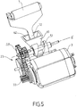
Figure 4 est une vue en perspective de l'intérieur de l'appareil selon la deuxième variante ; - La
Figure 5 est une vue en perspective de la transmission mécanique de l'élément massant illustré enfigure 4 . - La
Figure 6 est une vue en perspective de l'enchainement de l'élément massant, l'élément vibrant et la came illustrés enfigure 4 ; - La
Figure 7 est une vue de coupe schématique du boitier de l'appareil ; - La
Figure 8 est une vue de coupe schématique du boitier de l'appareil avec le bloc bi-traitement monté ; - La
Figure 9 est une vue en perspective de l'appareil avec la tête de massage montée sur le boitier ; - La
Figure 10 est une vue de coupe schématique du boitier de l'appareil avec la tête de massage montée sur le boitier. - La
Figure 11 est une vue en perspective de l'ensemble de l'appareil comprenant un système de flux d'air.
- The
Figure 1 is a perspective view of the entire body care apparatus; - The
Figure 2 is a perspective view of the inner construction of the bi-processing block and its gear train according to the first variant of the invention; - The
Figure 3 is an exploded view of the massaging element with its training according to the first variant; - The
Figure 4 is a perspective view of the interior of the apparatus according to the second variant; - The
Figure 5 is a perspective view of the mechanical transmission of the massaging element illustrated in FIG.figure 4 . - The
Figure 6 is a perspective view of the sequence of the massaging element, the vibrating element and the cam illustrated in FIG.figure 4 ; - The
Figure 7 is a schematic sectional view of the case of the apparatus; - The
Figure 8 is a schematic sectional view of the device housing with the bi-processing block mounted; - The
Figure 9 is a perspective view of the device with the massage head mounted on the housing; - The
Figure 10 is a schematic sectional view of the camera case with the massage head mounted on the case. - The
Figure 11 is a perspective view of the entire apparatus including an airflow system.
Un appareil de soin corporel telle qu'illustré à la
Un tel cylindre d'épilation 4 comprend plusieurs modules d'arrachage composés de pinces ou de disques rotatifs destinés à exercer une fermeture rapide pour pincer les poils. Le cylindre d'épilation 4 est rotatif par rapport à un axe d'épilation Δ parallèle au plan de la peau à épiler et est entrainé en rotation par le pignon d'entrainement 42. Le cylindre d'épilation comprend des moyens de définition des secteurs angulaires 41, par exemple, formé par une ou plusieurs cames associées à des chemins de cames adaptés afin que les pinces soient ouvertes au moment où elles commencent à affleurer au niveau d'une fenêtre d'épilation 92 et se ferment alors qu'elles affleurent encore et bien avant de sortir de la fenêtre d'épilation 92.Such a
Toujours à la
Le bloc bi-traitement 8 comprend une base 82 solidaire à un capot 83 qui reçoit le cylindre d'épilation 4 ; l'élément massant 7 et leur mécanisme d'entrainement. La base 82 comprend en partie inférieure des crochets 25 venant automatiquement, sous la poussée d'un ressort, en prise avec des moyens de verrouillage 222 situés en partie supérieure du boitier 2. Un bouton de déverrouillage 24 est prévu sur un côté du boîtier 2 à l'aide duquel on pousse les moyens de verrouillage 222 pour libérer les crochets 25 et retirer le bloc bi-traitement 8. Grâce au système de verrouillage réversible, l'ensemble du bloc bi-traitement comprenant le cylindre d'épilation 4 et l'élément massant 7 est démontable du boîtier 2 et interchangeable avec d'autres accessoires de traitement.The
Avant de présenter les différents modes d'actionnement de la barrette, il faudrait tout d'abord comprendre qu'il serait préférable d'amener son mouvement tangentiel de manière fermé et intime à la peau quel que soit le positionnement angulaire du boîtier 2 de l'appareil par rapport au plan de travail ce qui permettra de maximiser l'oscillation de la barrette et augmenter l'efficacité de l'effet antidouleur.Before presenting the different modes of actuation of the bar, it should first be understood that it would be preferable to bring tangential movement in a closed and intimate manner to the skin regardless of the angular positioning of the
A cet effet, la barrette est incorporée dans un volet mobile 9 qui est lui-même logé dans le capot 83 du bloc. En effet, comme cela a été dit précédemment, le cylindre d'épilation 4 affleure au niveau de la fenêtre d'épilation 92 aménagé dans le corps du bloc bi-traitement. Selon l'exemple illustré la fenêtre d'épilation 92 est délimitée par, d'une part, deux bords longitudinaux 91 et 94 parallèles entre eux et à l'axe d'épilation Δ et, d'autre part, deux bord transversaux qui sont parallèles entre eux et présentent une forme arquée en étant contenus dans des plans perpendiculaires à l'axe de rotation Δ. L'un des bords longitudinaux, ici le bord inférieur 94, est fixe étant formé par un bord du capot 83. Selon l'invention, l'autre bord longitudinal est mobile en étant formé par le volet mobile 9 en rotation autour de l'axe d'épilation Δ. Ce bord longitudinal mobile est désigné par la référence 91. Le volet mobile 9 comprend un talon d'appui 93 qui s'étend dans le prolongement du bord longitudinal mobile 91 à l'opposé de la fenêtre d'épilation 92. Le talon définit alors une surface de contact avec la peau de la zone à épiler. Dans le but de garantir un arrachage aussi performant que possible des poils de la zone à épiler quelle que soit l'inclinaison du boîtier 2 par rapport à la peau, le volet mobile 9 est de préférence solidaire des moyens de définition des secteurs angulaires 41. Ainsi, les moyens de définition des secteurs angulaires 41 se trouvent mobiles en rotation autour de l'axe d'épilation Δ et suivent les variations de l'inclinaison du boîtier 2 par rapport à la peau de la zone à épiler. Le volet mobile 9 comprend en outre une fenêtre de massage 95 donnant l'accès à l'élément massant 7. Ce dernier comprend une rainure circulaire 73 formant avec des lignes de protubérance de la fenêtre de massage 95 une liaison glissière, ce qui assure le mouvement va et vient de la barrette dans un plan parallèle à celui du volet mobile 9. Ainsi, la barrette suit le mouvement du volet mobile 9 quel que soit l'inclinaison de l'appareil et garantit un effet massage optimal. On remarque que, sous l'effort de frottement entre le volet mobile 9 et le pignon d'entrainement 42 du cylindre d'épilation 4, le volet mobile 9 ainsi que la barrette antidouleur seront toujours amenés à solliciter la peau et donc maintenus en contact intime avec la peau.For this purpose, the bar is incorporated in a
Nous allons maintenant expliquer en détail l'entrainement de l'élément massant 7. Dans un premier mode de réalisation comme illustré à la
Afin de pouvoir transmettre le mouvement en rotation de la came 5 en un mouvement de translation de l'élément massant 7, la came 5 présente une rainure 51 dans laquelle vient s'insérer un cylindre dépassant 71 solidaire à l'élément massant 7, le cylindre dépassant 71 étant guidé par la rampe de la rainure 51 afin d'amener la barrette à un mouvement de va-et-vient. L'avantage d'un tel système d'entrainement est de pouvoir moduler la vitesse de la came 5 de manière à ce qu'elle soit adaptée à la fréquence de frottement de la barrette sur la peau. Les pignons faisant partie du train d'engrenage translation 81 présentent des diamètres et des nombres de dents à un certain rapport, ce qui permet d'amplifier ou réduire la vitesse de sortie du boîtier en modifiant ces paramètres.In order to be able to transmit the rotational movement of the
Dans une variante de ce premier mode de réalisation non illustré, on peut supprimer le pignon de vitesse 60 tout en mettant le pignon de came 52 en contact direct avec le pignon d'entrainement 42. Dans ce cas là, on peut gagner en matière d'espace du bloc bi-traitement. Toutefois, cette variante n'est pas préférable puisqu'une collision se produit entre les dents du pignon d'entrainement 42 et le volet mobile 9 quand le pignon de came 52 est trop près du cylindre d'épilation 4.In a variant of this first embodiment that is not illustrated, it is possible to eliminate the
Dans le but encore d'améliorer l'usage de l'appareil, la came 5 est préférablement une double came ayant une rainure permettant de faire déplacer la barrette dans un sens ou dans l'autre. Ceci présente un avantage de pouvoir doubler la fréquence de vibration de la barrette et aussi de garantir la sécurité et l'efficacité de l'appareil. Quand le cylindre d'épilation mis en marche est en contact avec la peau, il peut y avoir un coincement de poils entre le cylindre et le volet mobile, la double came permet de tourner manuellement le cylindre d'épilation dans le sens opposé à celui du fonctionnement pour dépannage ou nettoyage.In order to further improve the use of the apparatus, the
Dans un deuxième mode de réalisation de l'invention comme illustré aux
Selon ce mode de réalisation, la barrette comprend un bras d'actionnement 72 sous forme de deux tiges métalliques destinées à s'insérer dans le logement 62 et à être guidées par les parois du logement 62. Sachant que le logement 62 peut être débouchant tout en gardant le même degré de liberté pour le mouvement du bras d'actionnement. Avec une telle construction de l'appareil, la fréquence de vibration de la barrette est contrôlée et optimisée et le pignon de came 52 peut être entrainé en rotation à une vitesse supérieure à celle de la roue de transmission 221.According to this embodiment, the bar comprises an
On peut aussi, bien sûr, utiliser la double came présentée dans le premier mode de réalisation dans le but d'obtenir une fréquence plus importante.One can also, of course, use the double cam presented in the first embodiment in order to obtain a higher frequency.
Le fait d'avoir un bloc bi-traitement 8 démontable intégrant le cylindre d'épilation 4 et l'élément massant 7 permet de rendre l'appareil plus compact et multifonctionnel en mettant d'autres accessoires interchangeables avec le bloc bi-traitement nécessitant un mouvement motorisé. A titre indicatif et non limitatif, le boîtier 2 de l'appareil est adapté pour recevoir une tête de massage comme illustré à la
Il serait également possible de combiner l'épilation antidouleur à d'autres traitement de la peau, de façon à ce que l'épilation se fasse entre deux actions antidouleur séparées mises en série. Comme exemple illustré à la
Bien entendu, d'autres modifications peuvent être apportées à l'invention dans le cadre des revendications annexées.Of course, other modifications may be made to the invention within the scope of the appended claims.
Claims (15)
- Appliance (1) for body care comprising- a case (2) which encloses an electric motor (3) and a gear train (22) driven by said motor (3),- a depilatory cylinder (4) rotating about a depilatory axis (Δ) parallel to the plane of the skin to be treated, said depilatory cylinder (4) comprising at one of its ends a drive pinion (42) intended to be driven by said gear train (22),- a massaging element (7) intended to be in contact with the skin and to be driven in a translation oscillating motorised movement in a direction parallel to the depilatory axis (Δ),Characterised in that it comprises a two-treatment unit (8) integrating said massaging element (7) and said depilatory cylinder (4) and in that said two-treatment unit (8) is mounted interchangeably on the case (2) of the appliance, and in that said two-treatment unit (8) comprises a mobile flap (9) in rotation of said depilatory axis (Δ) which defines at least one mobile longitudinal edge (91) of a depilatory window (92) and which comprises a support bracket (93) on the depilatory zone extending in the extension of the mobile longitudinal edge (91) opposite the depilatory window (92), and in that the massaging element (7) is mounted opposite the mobile longitudinal edge (91) of the support bracket and that there is a slide link in relation to the mobile flap (9) in a direction parallel to said depilatory axis (Δ)
- Appliance according to claim 1, characterised in that the depilatory cylinder comprises means for defining angular segments (41) and that the mobile flap (9) is integral with said means for defining angular segments (41) in such a way as to provide a modification of the position of the angular segments in relation to the two-treatment unit (8) according to the orientation of the mobile flap (9).
- Appliance according to any one of the preceding claims, characterised in that it comprises a cam (5) rotating about a secondary axis (Δ') parallel to the depilatory axis (Δ), with the cam (5) being mounted on a rod (53) and intended to drive said massaging element (7).
- Appliance according to the preceding claim, characterised in that said rod (53) is integral with the mobile flap (9).
- Appliance according to the preceding claim, characterised in that the cam (5) comprises at one of its ends a cam pinion (52) and that the cam (5) is intended to be driven by the depilatory cylinder (4) by means of a translation gear train (81).
- Appliance according to the preceding claim, characterised in that said translation gear train (81) comprises said cam pinion (52), the drive pinion (42) and at least one speed pinion (60) between the two.
- Appliance according to claim 5 or 6, characterised in that the cam comprises a groove (51) formed in order to allow for a rotation of the cam (5) in the two opposite directions.
- Appliance according to claim 3, characterised in that the rod (53) is integral with the case (2).
- Appliance according to claim 8, characterised in that said two-treatment unit (8) comprises at least one actuating arm (72) of the massaging element (7) perpendicular to the depilatory axis (Δ) intended to be driven by the motor (3) by means of a mechanical transmission (23).
- Appliance according to the preceding claim, characterised in that said mechanical transmission (23) comprises at least said cam pinion (52), a motor pinion (33) and a vibrating element (61) intended to be oscillated by the cam (5), said vibrating element (61) comprising a housing (62) intended to receive said actuating arm (72) and to guide it in translation in a direction parallel to the depilatory axis (Δ).
- Appliance according to any one of the preceding claims, characterised in that the massaging element (7) is a barrette having a substantially planar contact surface with the skin.
- Appliance according to any one of claims 1 to 10, characterised in that the massaging element (7) is a barrette having a contact surface with the skin comprising protuberances.
- Appliance according to claim 11 or 12, characterised in that the barrette is made of ZAMAK material.
- Appliance according to any one of the preceding claims, characterised in that it comprises at least one massaging head (88) mounted interchangeably on the case (2).
- Appliance according to any one of the preceding claims, characterised in that it comprises an air flow system.
Applications Claiming Priority (1)
| Application Number | Priority Date | Filing Date | Title |
|---|---|---|---|
| FR1255194A FR2991144B1 (en) | 2012-06-04 | 2012-06-04 | HEALING ANTI-PAIN HEAD |
Publications (3)
| Publication Number | Publication Date |
|---|---|
| EP2671465A2 EP2671465A2 (en) | 2013-12-11 |
| EP2671465A3 EP2671465A3 (en) | 2016-01-13 |
| EP2671465B1 true EP2671465B1 (en) | 2018-04-18 |
Family
ID=48446210
Family Applications (1)
| Application Number | Title | Priority Date | Filing Date |
|---|---|---|---|
| EP13169402.8A Active EP2671465B1 (en) | 2012-06-04 | 2013-05-27 | Pain-free depilation head |
Country Status (5)
| Country | Link |
|---|---|
| EP (1) | EP2671465B1 (en) |
| CN (1) | CN203467888U (en) |
| ES (1) | ES2669061T3 (en) |
| FR (1) | FR2991144B1 (en) |
| PT (1) | PT2671465T (en) |
Families Citing this family (3)
| Publication number | Priority date | Publication date | Assignee | Title |
|---|---|---|---|---|
| CN104802194A (en) * | 2015-05-06 | 2015-07-29 | 浙江美森电器有限公司 | Shaver capable of repairing skin injury caused by shaving |
| JP7116184B2 (en) * | 2018-03-26 | 2022-08-09 | ブラウン ゲーエムベーハー | skin treatment device |
| CN113975008B (en) * | 2021-10-27 | 2023-07-14 | 南京索酷信息科技股份有限公司 | Auxiliary device for rehabilitation nursing of prosthetic patient based on 5G Internet |
Family Cites Families (6)
| Publication number | Priority date | Publication date | Assignee | Title |
|---|---|---|---|---|
| FR2800584B1 (en) * | 1999-11-05 | 2001-12-28 | Seb Sa | EXFOLIATION ACCESSORY FOR A HAIR REMOVER |
| FR2802393B1 (en) * | 1999-12-17 | 2002-02-01 | Seb Sa | ADAPTABLE ACCESSORY ON A HAIR REMOVER |
| FR2810516B1 (en) * | 2000-06-27 | 2002-08-30 | Seb Sa | HAIR REMOVAL DEVICE COMPRISING PAIN RELIEF MEANS |
| FR2892902B1 (en) * | 2005-11-07 | 2007-12-14 | Seb Sa | APPARATUS FOR WEIGHING INCLUDING A DEVICE FOR CUTTING HAIR. |
| FR2904514B1 (en) | 2006-08-01 | 2008-09-05 | Seb Sa | APPARATUS FOR WEIGHING WITH ANTI-COLOR MEANS |
| RU2478326C2 (en) * | 2008-02-22 | 2013-04-10 | Конинклейке Филипс Электроникс Н.В. | Epilator with replaceable fittings |
-
2012
- 2012-06-04 FR FR1255194A patent/FR2991144B1/en not_active Expired - Fee Related
-
2013
- 2013-05-27 EP EP13169402.8A patent/EP2671465B1/en active Active
- 2013-05-27 ES ES13169402.8T patent/ES2669061T3/en active Active
- 2013-05-27 PT PT131694028T patent/PT2671465T/en unknown
- 2013-05-30 CN CN201320304476.5U patent/CN203467888U/en not_active Expired - Lifetime
Non-Patent Citations (1)
| Title |
|---|
| None * |
Also Published As
| Publication number | Publication date |
|---|---|
| PT2671465T (en) | 2018-05-21 |
| FR2991144B1 (en) | 2014-06-27 |
| ES2669061T3 (en) | 2018-05-23 |
| FR2991144A1 (en) | 2013-12-06 |
| EP2671465A2 (en) | 2013-12-11 |
| CN203467888U (en) | 2014-03-12 |
| EP2671465A3 (en) | 2016-01-13 |
Similar Documents
| Publication | Publication Date | Title |
|---|---|---|
| EP2735297B1 (en) | Massage apparatus with massage head provided with a massage roller | |
| EP2671465B1 (en) | Pain-free depilation head | |
| EP1884174B1 (en) | Hair-removing device with pain-reduction means | |
| FR2892902A1 (en) | APPARATUS FOR WEIGHING INCLUDING A DEVICE FOR CUTTING HAIR. | |
| EP1884172B1 (en) | Hair-removing device producing a flow of air | |
| EP1652447B1 (en) | Hair removal device comprising a skin treatment accessory | |
| EP1294249B1 (en) | Depilatory appliance comprising pain-killing means | |
| EP2462832A1 (en) | Epilator with a precision head | |
| EP1225818B1 (en) | Depilatory appliance with skin cleansing accessory | |
| FR2823080A1 (en) | HAIR REMOVAL APPARATUS | |
| EP1351590B1 (en) | Hair-removal apparatus comprising a pain-relieving device | |
| EP1300095B1 (en) | Depilatory appliance comprising pain-killing means | |
| WO2003051154A1 (en) | Hair removal device comprising an exfoliating head | |
| EP3193658B1 (en) | Skin treatment apparatus with vibrating elements | |
| EP1255464B1 (en) | Hair removing appliance with vibrating rotary roller | |
| EP1884173B1 (en) | Hair-removing device producing a flow of air with improved construction | |
| EP3272247B1 (en) | Depilator with precision head | |
| WO2014053766A1 (en) | Isostatic epilator comprising pivoting tweezers | |
| FR2775590A1 (en) | Vibratory stimulating device for skin tissue. |
Legal Events
| Date | Code | Title | Description |
|---|---|---|---|
| PUAI | Public reference made under article 153(3) epc to a published international application that has entered the european phase |
Free format text: ORIGINAL CODE: 0009012 |
|
| AK | Designated contracting states |
Kind code of ref document: A2 Designated state(s): AL AT BE BG CH CY CZ DE DK EE ES FI FR GB GR HR HU IE IS IT LI LT LU LV MC MK MT NL NO PL PT RO RS SE SI SK SM TR |
|
| AX | Request for extension of the european patent |
Extension state: BA ME |
|
| PUAL | Search report despatched |
Free format text: ORIGINAL CODE: 0009013 |
|
| AK | Designated contracting states |
Kind code of ref document: A3 Designated state(s): AL AT BE BG CH CY CZ DE DK EE ES FI FR GB GR HR HU IE IS IT LI LT LU LV MC MK MT NL NO PL PT RO RS SE SI SK SM TR |
|
| AX | Request for extension of the european patent |
Extension state: BA ME |
|
| RIC1 | Information provided on ipc code assigned before grant |
Ipc: A45D 26/00 20060101AFI20151207BHEP |
|
| 17P | Request for examination filed |
Effective date: 20160707 |
|
| RBV | Designated contracting states (corrected) |
Designated state(s): AL AT BE BG CH CY CZ DE DK EE ES FI FR GB GR HR HU IE IS IT LI LT LU LV MC MK MT NL NO PL PT RO RS SE SI SK SM TR |
|
| RAP1 | Party data changed (applicant data changed or rights of an application transferred) |
Owner name: SEB S.A. |
|
| 17Q | First examination report despatched |
Effective date: 20170117 |
|
| GRAP | Despatch of communication of intention to grant a patent |
Free format text: ORIGINAL CODE: EPIDOSNIGR1 |
|
| INTG | Intention to grant announced |
Effective date: 20171123 |
|
| GRAS | Grant fee paid |
Free format text: ORIGINAL CODE: EPIDOSNIGR3 |
|
| GRAA | (expected) grant |
Free format text: ORIGINAL CODE: 0009210 |
|
| AK | Designated contracting states |
Kind code of ref document: B1 Designated state(s): AL AT BE BG CH CY CZ DE DK EE ES FI FR GB GR HR HU IE IS IT LI LT LU LV MC MK MT NL NO PL PT RO RS SE SI SK SM TR |
|
| REG | Reference to a national code |
Ref country code: GB Ref legal event code: FG4D Free format text: NOT ENGLISH |
|
| REG | Reference to a national code |
Ref country code: CH Ref legal event code: EP |
|
| REG | Reference to a national code |
Ref country code: AT Ref legal event code: REF Ref document number: 989473 Country of ref document: AT Kind code of ref document: T Effective date: 20180515 |
|
| REG | Reference to a national code |
Ref country code: IE Ref legal event code: FG4D Free format text: LANGUAGE OF EP DOCUMENT: FRENCH |
|
| REG | Reference to a national code |
Ref country code: PT Ref legal event code: SC4A Ref document number: 2671465 Country of ref document: PT Date of ref document: 20180521 Kind code of ref document: T Free format text: AVAILABILITY OF NATIONAL TRANSLATION Effective date: 20180515 |
|
| REG | Reference to a national code |
Ref country code: ES Ref legal event code: FG2A Ref document number: 2669061 Country of ref document: ES Kind code of ref document: T3 Effective date: 20180523 |
|
| REG | Reference to a national code |
Ref country code: DE Ref legal event code: R096 Ref document number: 602013035980 Country of ref document: DE |
|
| REG | Reference to a national code |
Ref country code: FR Ref legal event code: PLFP Year of fee payment: 6 |
|
| REG | Reference to a national code |
Ref country code: NL Ref legal event code: MP Effective date: 20180418 |
|
| REG | Reference to a national code |
Ref country code: LT Ref legal event code: MG4D |
|
| PG25 | Lapsed in a contracting state [announced via postgrant information from national office to epo] |
Ref country code: NL Free format text: LAPSE BECAUSE OF FAILURE TO SUBMIT A TRANSLATION OF THE DESCRIPTION OR TO PAY THE FEE WITHIN THE PRESCRIBED TIME-LIMIT Effective date: 20180418 |
|
| PG25 | Lapsed in a contracting state [announced via postgrant information from national office to epo] |
Ref country code: SE Free format text: LAPSE BECAUSE OF FAILURE TO SUBMIT A TRANSLATION OF THE DESCRIPTION OR TO PAY THE FEE WITHIN THE PRESCRIBED TIME-LIMIT Effective date: 20180418 Ref country code: LT Free format text: LAPSE BECAUSE OF FAILURE TO SUBMIT A TRANSLATION OF THE DESCRIPTION OR TO PAY THE FEE WITHIN THE PRESCRIBED TIME-LIMIT Effective date: 20180418 Ref country code: AL Free format text: LAPSE BECAUSE OF FAILURE TO SUBMIT A TRANSLATION OF THE DESCRIPTION OR TO PAY THE FEE WITHIN THE PRESCRIBED TIME-LIMIT Effective date: 20180418 Ref country code: NO Free format text: LAPSE BECAUSE OF FAILURE TO SUBMIT A TRANSLATION OF THE DESCRIPTION OR TO PAY THE FEE WITHIN THE PRESCRIBED TIME-LIMIT Effective date: 20180718 Ref country code: PL Free format text: LAPSE BECAUSE OF FAILURE TO SUBMIT A TRANSLATION OF THE DESCRIPTION OR TO PAY THE FEE WITHIN THE PRESCRIBED TIME-LIMIT Effective date: 20180418 Ref country code: BG Free format text: LAPSE BECAUSE OF FAILURE TO SUBMIT A TRANSLATION OF THE DESCRIPTION OR TO PAY THE FEE WITHIN THE PRESCRIBED TIME-LIMIT Effective date: 20180718 Ref country code: FI Free format text: LAPSE BECAUSE OF FAILURE TO SUBMIT A TRANSLATION OF THE DESCRIPTION OR TO PAY THE FEE WITHIN THE PRESCRIBED TIME-LIMIT Effective date: 20180418 |
|
| PG25 | Lapsed in a contracting state [announced via postgrant information from national office to epo] |
Ref country code: RS Free format text: LAPSE BECAUSE OF FAILURE TO SUBMIT A TRANSLATION OF THE DESCRIPTION OR TO PAY THE FEE WITHIN THE PRESCRIBED TIME-LIMIT Effective date: 20180418 Ref country code: HR Free format text: LAPSE BECAUSE OF FAILURE TO SUBMIT A TRANSLATION OF THE DESCRIPTION OR TO PAY THE FEE WITHIN THE PRESCRIBED TIME-LIMIT Effective date: 20180418 Ref country code: GR Free format text: LAPSE BECAUSE OF FAILURE TO SUBMIT A TRANSLATION OF THE DESCRIPTION OR TO PAY THE FEE WITHIN THE PRESCRIBED TIME-LIMIT Effective date: 20180719 Ref country code: LV Free format text: LAPSE BECAUSE OF FAILURE TO SUBMIT A TRANSLATION OF THE DESCRIPTION OR TO PAY THE FEE WITHIN THE PRESCRIBED TIME-LIMIT Effective date: 20180418 |
|
| REG | Reference to a national code |
Ref country code: CH Ref legal event code: PL |
|
| REG | Reference to a national code |
Ref country code: AT Ref legal event code: MK05 Ref document number: 989473 Country of ref document: AT Kind code of ref document: T Effective date: 20180418 |
|
| REG | Reference to a national code |
Ref country code: DE Ref legal event code: R097 Ref document number: 602013035980 Country of ref document: DE |
|
| PG25 | Lapsed in a contracting state [announced via postgrant information from national office to epo] |
Ref country code: MC Free format text: LAPSE BECAUSE OF FAILURE TO SUBMIT A TRANSLATION OF THE DESCRIPTION OR TO PAY THE FEE WITHIN THE PRESCRIBED TIME-LIMIT Effective date: 20180418 Ref country code: DK Free format text: LAPSE BECAUSE OF FAILURE TO SUBMIT A TRANSLATION OF THE DESCRIPTION OR TO PAY THE FEE WITHIN THE PRESCRIBED TIME-LIMIT Effective date: 20180418 Ref country code: AT Free format text: LAPSE BECAUSE OF FAILURE TO SUBMIT A TRANSLATION OF THE DESCRIPTION OR TO PAY THE FEE WITHIN THE PRESCRIBED TIME-LIMIT Effective date: 20180418 Ref country code: SK Free format text: LAPSE BECAUSE OF FAILURE TO SUBMIT A TRANSLATION OF THE DESCRIPTION OR TO PAY THE FEE WITHIN THE PRESCRIBED TIME-LIMIT Effective date: 20180418 Ref country code: EE Free format text: LAPSE BECAUSE OF FAILURE TO SUBMIT A TRANSLATION OF THE DESCRIPTION OR TO PAY THE FEE WITHIN THE PRESCRIBED TIME-LIMIT Effective date: 20180418 Ref country code: RO Free format text: LAPSE BECAUSE OF FAILURE TO SUBMIT A TRANSLATION OF THE DESCRIPTION OR TO PAY THE FEE WITHIN THE PRESCRIBED TIME-LIMIT Effective date: 20180418 Ref country code: CZ Free format text: LAPSE BECAUSE OF FAILURE TO SUBMIT A TRANSLATION OF THE DESCRIPTION OR TO PAY THE FEE WITHIN THE PRESCRIBED TIME-LIMIT Effective date: 20180418 |
|
| REG | Reference to a national code |
Ref country code: IE Ref legal event code: MM4A |
|
| PLBE | No opposition filed within time limit |
Free format text: ORIGINAL CODE: 0009261 |
|
| STAA | Information on the status of an ep patent application or granted ep patent |
Free format text: STATUS: NO OPPOSITION FILED WITHIN TIME LIMIT |
|
| PG25 | Lapsed in a contracting state [announced via postgrant information from national office to epo] |
Ref country code: CH Free format text: LAPSE BECAUSE OF NON-PAYMENT OF DUE FEES Effective date: 20180531 Ref country code: SM Free format text: LAPSE BECAUSE OF FAILURE TO SUBMIT A TRANSLATION OF THE DESCRIPTION OR TO PAY THE FEE WITHIN THE PRESCRIBED TIME-LIMIT Effective date: 20180418 Ref country code: LI Free format text: LAPSE BECAUSE OF NON-PAYMENT OF DUE FEES Effective date: 20180531 |
|
| 26N | No opposition filed |
Effective date: 20190121 |
|
| PG25 | Lapsed in a contracting state [announced via postgrant information from national office to epo] |
Ref country code: LU Free format text: LAPSE BECAUSE OF NON-PAYMENT OF DUE FEES Effective date: 20180527 |
|
| PG25 | Lapsed in a contracting state [announced via postgrant information from national office to epo] |
Ref country code: IE Free format text: LAPSE BECAUSE OF NON-PAYMENT OF DUE FEES Effective date: 20180527 |
|
| PG25 | Lapsed in a contracting state [announced via postgrant information from national office to epo] |
Ref country code: SI Free format text: LAPSE BECAUSE OF FAILURE TO SUBMIT A TRANSLATION OF THE DESCRIPTION OR TO PAY THE FEE WITHIN THE PRESCRIBED TIME-LIMIT Effective date: 20180418 |
|
| PG25 | Lapsed in a contracting state [announced via postgrant information from national office to epo] |
Ref country code: MT Free format text: LAPSE BECAUSE OF FAILURE TO SUBMIT A TRANSLATION OF THE DESCRIPTION OR TO PAY THE FEE WITHIN THE PRESCRIBED TIME-LIMIT Effective date: 20180418 |
|
| PG25 | Lapsed in a contracting state [announced via postgrant information from national office to epo] |
Ref country code: HU Free format text: LAPSE BECAUSE OF FAILURE TO SUBMIT A TRANSLATION OF THE DESCRIPTION OR TO PAY THE FEE WITHIN THE PRESCRIBED TIME-LIMIT; INVALID AB INITIO Effective date: 20130527 |
|
| PG25 | Lapsed in a contracting state [announced via postgrant information from national office to epo] |
Ref country code: CY Free format text: LAPSE BECAUSE OF FAILURE TO SUBMIT A TRANSLATION OF THE DESCRIPTION OR TO PAY THE FEE WITHIN THE PRESCRIBED TIME-LIMIT Effective date: 20180418 Ref country code: MK Free format text: LAPSE BECAUSE OF NON-PAYMENT OF DUE FEES Effective date: 20180418 |
|
| PG25 | Lapsed in a contracting state [announced via postgrant information from national office to epo] |
Ref country code: IS Free format text: LAPSE BECAUSE OF FAILURE TO SUBMIT A TRANSLATION OF THE DESCRIPTION OR TO PAY THE FEE WITHIN THE PRESCRIBED TIME-LIMIT Effective date: 20180818 |
|
| PGFP | Annual fee paid to national office [announced via postgrant information from national office to epo] |
Ref country code: DE Payment date: 20200513 Year of fee payment: 8 Ref country code: ES Payment date: 20200616 Year of fee payment: 8 Ref country code: TR Payment date: 20200511 Year of fee payment: 8 Ref country code: PT Payment date: 20200417 Year of fee payment: 8 |
|
| PGFP | Annual fee paid to national office [announced via postgrant information from national office to epo] |
Ref country code: GB Payment date: 20200527 Year of fee payment: 8 Ref country code: IT Payment date: 20200512 Year of fee payment: 8 Ref country code: BE Payment date: 20200519 Year of fee payment: 8 |
|
| REG | Reference to a national code |
Ref country code: DE Ref legal event code: R119 Ref document number: 602013035980 Country of ref document: DE |
|
| GBPC | Gb: european patent ceased through non-payment of renewal fee |
Effective date: 20210527 |
|
| PG25 | Lapsed in a contracting state [announced via postgrant information from national office to epo] |
Ref country code: PT Free format text: LAPSE BECAUSE OF NON-PAYMENT OF DUE FEES Effective date: 20211129 |
|
| REG | Reference to a national code |
Ref country code: BE Ref legal event code: MM Effective date: 20210531 |
|
| PG25 | Lapsed in a contracting state [announced via postgrant information from national office to epo] |
Ref country code: GB Free format text: LAPSE BECAUSE OF NON-PAYMENT OF DUE FEES Effective date: 20210527 Ref country code: DE Free format text: LAPSE BECAUSE OF NON-PAYMENT OF DUE FEES Effective date: 20211201 |
|
| PG25 | Lapsed in a contracting state [announced via postgrant information from national office to epo] |
Ref country code: BE Free format text: LAPSE BECAUSE OF NON-PAYMENT OF DUE FEES Effective date: 20210531 |
|
| REG | Reference to a national code |
Ref country code: ES Ref legal event code: FD2A Effective date: 20220829 |
|
| PG25 | Lapsed in a contracting state [announced via postgrant information from national office to epo] |
Ref country code: ES Free format text: LAPSE BECAUSE OF NON-PAYMENT OF DUE FEES Effective date: 20210528 |
|
| PG25 | Lapsed in a contracting state [announced via postgrant information from national office to epo] |
Ref country code: IT Free format text: LAPSE BECAUSE OF NON-PAYMENT OF DUE FEES Effective date: 20200527 |
|
| P01 | Opt-out of the competence of the unified patent court (upc) registered |
Effective date: 20230517 |
|
| PGFP | Annual fee paid to national office [announced via postgrant information from national office to epo] |
Ref country code: FR Payment date: 20230523 Year of fee payment: 11 |