EP2670955B1 - Welle, insbesondere nockenwelle mit einem hohlen wellenabschnitt - Google Patents
Welle, insbesondere nockenwelle mit einem hohlen wellenabschnitt Download PDFInfo
- Publication number
- EP2670955B1 EP2670955B1 EP12703756.2A EP12703756A EP2670955B1 EP 2670955 B1 EP2670955 B1 EP 2670955B1 EP 12703756 A EP12703756 A EP 12703756A EP 2670955 B1 EP2670955 B1 EP 2670955B1
- Authority
- EP
- European Patent Office
- Prior art keywords
- shaft
- hollow shaft
- openings
- shaft according
- protection device
- Prior art date
- Legal status (The legal status is an assumption and is not a legal conclusion. Google has not performed a legal analysis and makes no representation as to the accuracy of the status listed.)
- Active
Links
Images


Classifications
-
- F—MECHANICAL ENGINEERING; LIGHTING; HEATING; WEAPONS; BLASTING
- F01—MACHINES OR ENGINES IN GENERAL; ENGINE PLANTS IN GENERAL; STEAM ENGINES
- F01L—CYCLICALLY OPERATING VALVES FOR MACHINES OR ENGINES
- F01L1/00—Valve-gear or valve arrangements, e.g. lift-valve gear
- F01L1/02—Valve drive
- F01L1/04—Valve drive by means of cams, camshafts, cam discs, eccentrics or the like
- F01L1/047—Camshafts
-
- F—MECHANICAL ENGINEERING; LIGHTING; HEATING; WEAPONS; BLASTING
- F01—MACHINES OR ENGINES IN GENERAL; ENGINE PLANTS IN GENERAL; STEAM ENGINES
- F01L—CYCLICALLY OPERATING VALVES FOR MACHINES OR ENGINES
- F01L1/00—Valve-gear or valve arrangements, e.g. lift-valve gear
- F01L1/46—Component parts, details, or accessories, not provided for in preceding subgroups
-
- F—MECHANICAL ENGINEERING; LIGHTING; HEATING; WEAPONS; BLASTING
- F01—MACHINES OR ENGINES IN GENERAL; ENGINE PLANTS IN GENERAL; STEAM ENGINES
- F01M—LUBRICATING OF MACHINES OR ENGINES IN GENERAL; LUBRICATING INTERNAL COMBUSTION ENGINES; CRANKCASE VENTILATING
- F01M13/00—Crankcase ventilating or breathing
- F01M13/04—Crankcase ventilating or breathing having means for purifying air before leaving crankcase, e.g. removing oil
-
- F—MECHANICAL ENGINEERING; LIGHTING; HEATING; WEAPONS; BLASTING
- F02—COMBUSTION ENGINES; HOT-GAS OR COMBUSTION-PRODUCT ENGINE PLANTS
- F02B—INTERNAL-COMBUSTION PISTON ENGINES; COMBUSTION ENGINES IN GENERAL
- F02B67/00—Engines characterised by the arrangement of auxiliary apparatus not being otherwise provided for, e.g. the apparatus having different functions; Driving auxiliary apparatus from engines, not otherwise provided for
- F02B67/04—Engines characterised by the arrangement of auxiliary apparatus not being otherwise provided for, e.g. the apparatus having different functions; Driving auxiliary apparatus from engines, not otherwise provided for of mechanically-driven auxiliary apparatus
- F02B67/06—Engines characterised by the arrangement of auxiliary apparatus not being otherwise provided for, e.g. the apparatus having different functions; Driving auxiliary apparatus from engines, not otherwise provided for of mechanically-driven auxiliary apparatus driven by means of chains, belts, or like endless members
-
- F—MECHANICAL ENGINEERING; LIGHTING; HEATING; WEAPONS; BLASTING
- F01—MACHINES OR ENGINES IN GENERAL; ENGINE PLANTS IN GENERAL; STEAM ENGINES
- F01L—CYCLICALLY OPERATING VALVES FOR MACHINES OR ENGINES
- F01L1/00—Valve-gear or valve arrangements, e.g. lift-valve gear
- F01L1/02—Valve drive
- F01L1/04—Valve drive by means of cams, camshafts, cam discs, eccentrics or the like
- F01L1/047—Camshafts
- F01L2001/0475—Hollow camshafts
-
- F—MECHANICAL ENGINEERING; LIGHTING; HEATING; WEAPONS; BLASTING
- F01—MACHINES OR ENGINES IN GENERAL; ENGINE PLANTS IN GENERAL; STEAM ENGINES
- F01L—CYCLICALLY OPERATING VALVES FOR MACHINES OR ENGINES
- F01L1/00—Valve-gear or valve arrangements, e.g. lift-valve gear
- F01L1/02—Valve drive
- F01L1/04—Valve drive by means of cams, camshafts, cam discs, eccentrics or the like
- F01L1/047—Camshafts
- F01L2001/0476—Camshaft bearings
-
- F—MECHANICAL ENGINEERING; LIGHTING; HEATING; WEAPONS; BLASTING
- F01—MACHINES OR ENGINES IN GENERAL; ENGINE PLANTS IN GENERAL; STEAM ENGINES
- F01M—LUBRICATING OF MACHINES OR ENGINES IN GENERAL; LUBRICATING INTERNAL COMBUSTION ENGINES; CRANKCASE VENTILATING
- F01M13/00—Crankcase ventilating or breathing
- F01M13/04—Crankcase ventilating or breathing having means for purifying air before leaving crankcase, e.g. removing oil
- F01M2013/0422—Separating oil and gas with a centrifuge device
-
- Y—GENERAL TAGGING OF NEW TECHNOLOGICAL DEVELOPMENTS; GENERAL TAGGING OF CROSS-SECTIONAL TECHNOLOGIES SPANNING OVER SEVERAL SECTIONS OF THE IPC; TECHNICAL SUBJECTS COVERED BY FORMER USPC CROSS-REFERENCE ART COLLECTIONS [XRACs] AND DIGESTS
- Y10—TECHNICAL SUBJECTS COVERED BY FORMER USPC
- Y10T—TECHNICAL SUBJECTS COVERED BY FORMER US CLASSIFICATION
- Y10T74/00—Machine element or mechanism
- Y10T74/21—Elements
- Y10T74/2101—Cams
Definitions
- the invention relates to a shaft, in particular camshaft with a hollow shaft portion, according to the preamble of claim 1.
- blowby gas In internal combustion engines and piston compressors leakage losses are observed in practice, which are due to an incomplete seal. These leakage losses are referred to as blowby gas and contain a significant amount of oil. With respect to internal combustion engines, it is therefore customary to direct the blow-by gas accumulating in the valve chamber back into the intake tract of the internal combustion engine. On the one hand to minimize the loss of oil by blow-by gas and on the other hand to ensure optimum combustion and minimum environmental impact, it is known to subject the blowby gas to oil separation and to pass the separated oil back into the oil circuit.
- the blow-by gas is discharged through the hollow shaft section, whereby an oil separation device can also be integrated directly into the hollow shaft section.
- oil is often present in different droplet sizes.
- large oil droplets or oil splashes are often observed in the vicinity of a camshaft.
- Such large droplets or splashes can form, for example, if there is an oil bath or an oil foam in the area of the camshaft.
- an oil jet reaches the shaft and in particular the hollow shaft section with the inlet opening for the discharge of the blow-by gas.
- a camshaft having a hollow shaft portion, which has at least one radial inlet opening for the discharge of a gas through the hollow shaft portion and with a splash guard, which is arranged in the region of the radial inlet opening on the hollow shaft portion, is known from EP 1 880 085 B1 known, wherein on the outer circumference of the shaft for the separation of oil, a pre-separator and an integrated in the hollow shaft portion swirl generator are provided as Endabscheider.
- the pre-separator is funnel-shaped and covers a plurality of radial inlet openings of the hollow shaft portion in the radial direction.
- the effect of splash protection is imperfect because obliquely injecting oil droplets or jets can not be prevented.
- the pre-separator is also constructed comparatively expensive and requires a considerable amount of space.
- a shaft according to the preamble of claim 1 is known from US 4,714,139 known.
- An impeller, which has a certain splash protection allows is formed as an integral part of a shaft body, resulting in a relatively complex shape.
- the invention has for its object to provide a shaft with a hollow shaft portion and at least one radial inlet opening in the hollow shaft portion, wherein at least largely prevented by a structurally simple spray protection device, the injection of large oil droplets or oil jets in the at least one inlet opening ,
- the object of the invention and solution of the problem is a shaft according to claim 1.
- Such a configuration can be achieved that essentially only blow-by gas passes into the passage openings and subsequently into the at least one inlet opening of the hollow shaft portion, while large oil droplets, oil spills and jets are held, the effectiveness of the splash guard usually increases with increasing speed of the shaft.
- the projections generate upon rotation of the shaft a gas flow in the direction of rotation, which prevents at least to some extent the spewing of oil droplets or even the injection of an oil jet into the passage openings of the splash guard and in the at least one inlet opening of the hollow shaft portion. Furthermore, it should be noted that large oil droplets and splashes can not follow the rotation of the splash guard to the same extent as the blow-by gas. Thus, oil droplets and splashes are increasingly deposited at the rotation of the shaft due to their mass inertia at the projections, while the blowby gas follow the rotational movement and can flow into the passages.
- the passages are so as it were sealed off from the comparatively sluggish droplets of oil and splashes by the projections which are arranged between the passage openings.
- the efficiency of this foreclosure depends on the one hand on the shape of the Vorspünge, in particular their height and orientation and on the other hand on the volume flow of the blow-by gas. As the volume flow of the blow-by gas increases, under certain circumstances it can no longer be completely avoided that even larger oil droplets are entrained and get into the hollow shaft section. Nevertheless, the inventive design of the shaft with the described splash guard is characterized by a very efficient and extensive separation of larger oil particles. Even if the shaft or even the splash guard partially immersed in an oil bath, the penetration of oil can be effectively prevented. An oil bath in the region of a camshaft can occur in practice under extreme loads on an engine, for example an increased oil level in the cylinder head or during strong acceleration or braking maneuvers.
- the splash guard is designed according to a preferred embodiment of the invention so that the fine oil droplets of the blow-by gas are not deposited.
- Such separation of the oil from the blow-by gas preferably takes place in a separate, downstream oil separation device, which is provided, for example, in the form of a helical flight or several helical flights within the hollow shaft section.
- a separate, downstream oil separation device which is provided, for example, in the form of a helical flight or several helical flights within the hollow shaft section.
- the advantage that such a downstream ⁇ labscheidevoriques is not additionally burdened by oil splash or the like.
- the jacket has a sleeve-shaped middle section, from which the projections protrude.
- the sleeve-shaped central portion is expediently substantially cylindrical or slightly conical.
- the jacket thus has a simple shape, on which the projections and openings can be easily formed.
- the splash guard can be designed as a molded part, in particular cast part, whereby a simple production is possible.
- the splash guard can be shrunk similar to cams or fixed by the expansion of the hollow shaft portion. But since it is a mechanically comparatively low-loaded component, a simplified assembly is possible.
- the splash guard may also be formed of segments, in particular two longitudinally divided segments.
- the individual segments are then placed on the region of the hollow shaft portion at the at least one radial inlet opening and clipped.
- the splash guard can be fixed with adhesive on the hollow shaft portion or assembled from the segments. Additionally or alternatively, it is also possible to provide on the splash guard and the hollow shaft portion cooperating interlocking elements, which cause a fixation.
- the splash guard it is advantageous if viewed in the longitudinal direction of the shaft at one end and preferably at both ends is radially enlarged, for which purpose, for example, flange-shaped formations can be provided.
- blow-by gas can easily dislodge the radially exposed jacket however, with the widened ends of the splash guard injecting oil from immediately adjacent means of the shaft, such as adjacent cams, can be effectively prevented.
- the space available in the longitudinal direction of the shaft and in the radial direction must be taken into account.
- the projections are formed as ribs which extend straight or with a certain inclination in the longitudinal direction of the shaft.
- the shaft is designed as a camshaft, this always has a predetermined direction of rotation. In other waves, a preferred direction of rotation is usually set. If a predetermined or at least a preferred direction of rotation is present, the projections are expediently oriented in such a way that separated oil is thrown outwards during the rotation in the predetermined or preferred direction of rotation. In an embodiment of the projections as ribs, these can thus be tilted such that the free ends of the ribs point away from the predetermined or preferred direction of rotation.
- the tilting with respect to an alignment extending exactly in the radial direction can be, for example, between 10 ° and 40 °, in particular between 15 ° and 30 °.
- the passage openings are protected by the rotational movement through the projections arranged between the passage openings. If the shaft has a predetermined or preferred direction of rotation, it is advantageous if, viewed in the direction of rotation, a projection is provided directly in front of each passage opening.
- the protection of the passage openings before injecting oil is further improved when the Projections as described above against the direction of rotation are tilted and as exactly in the radial direction, the passages cover to some extent.
- the passage openings may be, for example, longitudinal slots which extend substantially parallel to the longitudinal axis of the shaft. In combination with extending in the longitudinal direction of the shaft ribs then results in a particularly advantageous embodiment.
- the splash guard according to the invention is the at least one radial inlet opening of the hollow shaft portion upstream to effectively prevent injection of the oil. It is advantageous if a radial gap is provided between the jacket of the splash guard with the passage openings provided therein and the hollow shaft portion with the at least one passage opening. In the context of such an embodiment, namely, an offset in the longitudinal direction and / or circumferential direction of the shaft may be present between the passage openings and the at least one inlet opening. The gap then forms a flow channel for the gas to be discharged, with the further deflection of a separation of oil is possible. At least it is avoided that rapid oil droplets can pass without a deflection directly into the at least one inlet opening of the hollow shaft portion.
- the passage openings are to be distributed according to the circumference of the shell of the splash guard.
- the number of passage openings be an integral multiple of the number of inlet openings.
- the projections and openings are distributed in groups around the circumference of the shell in a uniform arrangement, in particular in pairs.
- a first projection, a first passage opening, a second projection and a second passage opening are then arranged directly one behind the other as viewed in the direction of rotation.
- a separate oil separation device is provided which can be arranged inside the hollow shaft section.
- a helical swirl generator can be provided with one or more screw flights, wherein the fine oil droplets of the blow-by gas are thrown outwards by the twisting movement and are deposited accordingly.
- the pitch of the screw flights By varying the pitch of the screw flights, the flow velocity in the flow direction can also be increased.
- a bypass valve with an adjoining bypass channel can be provided within the hollow shaft section, which bypasses the blowby gas at the oil separation device.
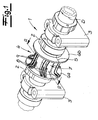
- the Fig. 1 shows a ready-to-install camshaft module with a camshaft 1, which has a plurality of cams 2 according to their usual structure and is supported by bearing blocks 3. Between two adjacent cams 2, a splash guard 4 is provided, whose operation will be explained in detail below.
- the splash guard 4 is composed of a separating surface 5 of two segments. Furthermore, it can be seen that the splash guard 4 has widened flange ends 6a, 6b and therebetween a sleeve-shaped, substantially cylindrical central portion 7. At the central portion 7 are passage openings 8 in the form of longitudinal slots and projections in the form of ribs 9 can be seen extending in the wavelength direction.
- the camshaft 1 has a hollow shaft section 10 which has at least one, in the exemplary embodiment, a total of six radial inlet openings 11a, 11b for the discharge of a blowby gas B through the hollow shaft section 10.
- the splash guard 4 is intended to avoid the injection of large oil droplets or oil jets directly into the radial inlet openings 11 a, 11 b into it.
- the ribs 9 and passage openings 8 are provided.
- a gas flow is generated in the circumferential direction, which prevents the spewing of large oil droplets or even the injection of an oil jet.
- Blowby gas B can follow the rotation of the camshaft 1 at a corresponding overpressure and flow into the inlet openings 11a, 11b.
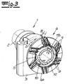
- the path of the blow-by gas B is in the sectional views of Fig. 2 to 4 indicated by dashed lines.
- the ribs are tilted relative to the predetermined direction of rotation D such that their free ends point away from the predetermined direction of rotation D.
- the tilt can for example be between 10 ° and 40 °, in particular between 15 ° and 30 °. In the embodiment, the tilt is about 25 °.
- the hollow shaft section 10 has different inlet openings 11a, 11b. Between the central portion 7 of the splash guard 4 and the hollow shaft portion 10, a radial gap 12 is formed, through which the blowby gas B flows. Three inlet openings 11a lead to an annular region within the hollow shaft section 10, which supplies the blow-by gas B for oil separation to a swirl generator, not shown.
- a bypass valve 13 with an adjoining bypass channel 14 is arranged centrally in the hollow shaft section 10. From the gap 12, the blowby gas B can pass through further inlet openings 11 b to the bypass valve 13.
- Fig. 4 is provided between the passage openings 8 of the splash guard 4 and the first inlet openings 11 a offset in the longitudinal direction.
- the blowby gas B is thus diverted, so too in this deflection even larger oil droplets can be deposited.
- inlet openings 11 b through which the blowby gas B can reach the bypass valve 13, lies in accordance with Fig. 2 at least one offset in the circumferential direction. This is achieved in that the passage openings 8 and ribs 9 are arranged in groups, each with two passage openings 8 and ribs 9. These six groups are then arranged so that the leading to the bypass valve 13 inlet openings 11 b are arranged exactly between two adjacent groups.
- the splash guard 4 is made of segments, in the embodiment of two longitudinally divided segments.
- the interface 5 between the segments is in the Fig. 2 and 3 recognizable, wherein the segments may be connected, for example, with an adhesive, in particular a two-component adhesive.
- an adhesive may also be provided.
- co-operating interlocking elements 15 may be provided on the splash guard 4 and the hollow shaft portion 10, which are exemplified in the Fig. 4 are shown.
Landscapes
- Engineering & Computer Science (AREA)
- Mechanical Engineering (AREA)
- General Engineering & Computer Science (AREA)
- Chemical & Material Sciences (AREA)
- Combustion & Propulsion (AREA)
- Valve-Gear Or Valve Arrangements (AREA)
- Lubrication Details And Ventilation Of Internal Combustion Engines (AREA)
Description
- Die Erfindung betrifft eine Welle, insbesondere Nockenwelle mit einem hohlen Wellenabschnitt, gemäß dem Oberbegriff des Patentanspruches 1.
- Bei Verbrennungsmotoren und Kolbenverdichtern werden in der Praxis Leckageverluste beobachtet, die auf eine nicht vollständige Abdichtung zurückzuführen sind. Diese Leckageverluste werden als Blowby-Gas bezeichnet und enthalten einen erheblichen Anteil an Öl. Bezogen auf Verbrennungsmotoren ist es deshalb üblich, das im Ventilraum anfallende Blowby-Gas zurück in den Ansaugtrakt des Verbrennungsmotors zu leiten. Um einerseits den Verlust an Öl durch Blowby-Gas zu minimieren und andererseits eine optimale Verbrennung und eine minimale Umweltbelastung zu gewährleisten, ist es bekannt, das Blowby-Gas einer Ölabscheidung zu unterziehen und das abgeschiedene Öl zurück in den Ölkreislauf zu führen.
- Bei einer gattungsgemäßen Welle, insbesondere Nockenwelle erfolgt die Abfuhr des Blowby-Gases durch den hohlen Wellenabschnitt, wobei in den hohlen Wellenabschnitt auch eine Ölabscheidevorrichtung unmittelbar integriert sein kann. Dabei ist zu berücksichtigen, dass in der Umgebung einer Nockenwelle Öl häufig in unterschiedlichsten Tröpfchengrößen vorliegt. Neben feinsten Öltröpfchen, die in dem Blowby-Gas enthalten und beispielsweise durch Drallerzeuger abzuscheiden sind, werden in der Umgebung einer Nockenwelle häufig auch große Öltröpfchen oder Ölspritzer beobachtet. Derartige große Tröpfchen oder Spritzer können sich beispielsweise bilden, wenn im Bereich der Nockenwelle ein Ölbad oder ein Ölschaum vorhanden ist. In ungünstigen Fällen kann es sogar vorkommen, dass ein Ölstrahl auf die Welle und insbesondere den hohlen Wellenabschnitt mit der Eintrittsöffnung zur Abführung des Blowby-Gases gelangt.
- Da eine nachträgliche Abscheidung von Öl mit einem hohen Aufwand verbunden ist, ist es von Vorteil, wenn bei einer gattungsgemäßen Welle große Öltröpfchen, Ölspritzer und Ölstrahlen von der zumindest einen Eintrittsöffnung des hohlen Wellenabschnittes ferngehalten werden. Trotz der Belüftung und der Möglichkeit der Abführung des Blowby-Gases können dann der Verlust an Öl sowie Verschmutzungen der nachgelagerten Einrichtungen gering gehalten werden. Wenn gemäß einer bevorzugten Ausgestaltung eine nachgelagerte Ölabscheidevorrichtung, beispielsweise innerhalb des hohlen Wellenabschnittes, vorhanden ist, muss diese Ölabscheidevorrichtung nur die feinen Öltröpfchen aus dem Blowby-Gas abscheiden, wodurch insgesamt eine sehr effiziente und zuverlässige Entölung des Gases erreicht werden kann.
- Eine Nockenwelle mit einem hohlen Wellenabschnitt, der zumindest eine radiale Eintrittsöffnung zur Abführung eines Gases durch den hohlen Wellenabschnitt aufweist und mit einer Spritzschutzeinrichtung, die im Bereich der radialen Eintrittsöffnung auf dem hohlen Wellenabschnitt angeordnet ist, ist aus der
EP 1 880 085 B1 bekannt, wobei auf dem äußeren Umfang der Welle zur Abtrennung von Öl ein Vorabscheider und ein in den hohlen Wellenabschnitt integrierter Drallerzeuger als Endabscheider vorgesehen sind. Der Vorabscheider ist trichterförmig ausgebildet und deckt mehrere radiale Eintrittsöffnungen des hohlen Wellenabschnittes in radialer Richtung ab. Die Wirkung als Spritzschutz ist jedoch unvollkommen, weil schräg einspritzende Öltröpfchen oder -strahlen nicht abgehalten werden können. Der Vorabscheider ist auch vergleichsweise aufwendig konstruiert und benötigt einen erheblichen Bauraum. - Eine Welle gemäß dem Oberbegriff des Patentanspruches 1 ist aus der
US 4,714,139 bekannt. Ein Pumpenrad, welches einen gewissen Spritzschutz ermöglicht, ist als integraler Bestandteil eines Wellenkörpers gebildet, wobei sich eine relativ aufwendige Form ergibt. - Vor diesem Hintergrund liegt der Erfindung die Aufgabe zugrunde, eine Welle mit einem hohlen Wellenabschnitt und zumindest einer radialen Eintrittsöffnung in dem hohlen Wellenabschnitt anzugeben, bei der durch eine konstruktiv einfach ausgestaltete Spritzschutzeinrichtung das Einspritzen großer Öltröpfchen oder Ölstrahlen in die zumindest eine Eintrittsöffnung zumindest weitgehend verhindert wird.
- Gegenstand der Erfindung und Lösung der Aufgabe ist eine Welle gemäß Patentanspruch 1. Durch eine solche Ausgestaltung kann erreicht werden, dass im Wesentlichen nur Blowby-Gas in die Durchtrittsöffnungen und nachfolgend in die zumindest eine Eintrittsöffnung des hohlen Wellenabschnittes gelangt, während große Öltröpfchen, Ölspritzer und -strahlen abgehalten werden, wobei die Wirksamkeit der Spritzschutzeinrichtung üblicherweise mit ansteigender Drehzahl der Welle zunimmt.
- Die Vorsprünge erzeugen bei der Drehung der Welle einen Gasstrom in Drehrichtung, der das Einschleudern von Öltröpfchen oder sogar das Einspritzen eines Ölstrahls zunächst in die Durchtrittsöffnungen der Spritzschutzeinrichtung und entsprechend auch in die zumindest eine Eintrittsöffnung des hohlen Wellenabschnittes zumindest in einem gewissen Maße verhindert. Des Weiteren ist zu berücksichtigen, dass große Öltröpfchen und -spritzer der Drehung der Spritzschutzeinrichtung nicht im gleichen Maße folgen können wie das Blowby-Gas. So werden also Öltröpfchen und -spritzer bei der Drehung der Welle aufgrund ihrer Masssenträgheit verstärkt an den Vorsprüngen abgeschieden, während das Blowby-Gas der Drehbewegung folgen und in die Durchtrittsöffnungen einströmen kann. Die Durchtrittsöffnungen werden also gewissermaßen gegenüber den vergleichsweise trägen Öltröpfchen und -spritzern durch die Vorsprünge, die zwischen den Durchtrittsöffnungen angeordnet sind, abgeschottet. Die Effizienz dieser Abschottung ist einerseits von der Form der Vorspünge, insbesondere deren Höhe und Ausrichtung sowie andererseits von dem Volumenstrom des Blowby-Gases abhängig. Bei zunehmendem Volumenstrom des Blowby-Gases kann unter Umständen nicht mehr vollständig vermieden werden, dass auch größere Öltröpfchen mitgerissen werden und in den hohlen Wellenabschnitt gelangen. Dennoch zeichnet sich die erfindungsgemäße Ausgestaltung der Welle mit der beschriebenen Spritzschutzeinrichtung durch eine sehr effiziente und weitgehende Abtrennung größerer Ölpartikel aus. Selbst wenn die Welle oder sogar die Spritzschutzeinrichtung teilweise in ein Ölbad eintauchen, kann wirksam das Eindringen von Öl verhindert werden. Ein Ölbad im Bereich einer Nockenwelle kann in der Praxis bei extremen Belastungen eines Motors, beispielsweise einem erhöhten Ölstand im Zylinderkopf oder bei starken Beschleunigungsoder Bremsmanövern auftreten.
- Die Spritzschutzeinrichtung ist gemäß einer bevorzugten Ausgestaltung der Erfindung so ausgeführt, dass die feinen Öltröpfchen des Blowby-Gases nicht abgeschieden werden. Eine solche Abscheidung des Öles aus dem Blowby-Gas erfolgt bevorzugt in einer separaten, nachgelagerten Ölabscheidevorrichtung, die beispielsweise in Form eines Schneckenganges oder mehrerer Schneckengänge innerhalb des hohlen Wellenabschnittes vorgesehen ist. Es ergibt sich aber im Rahmen der Erfindung der Vorteil, dass eine solche nachgelagerte Ölabscheidevorrichtung nicht noch zusätzlich durch Ölspritzer oder dergleichen belastet ist.
- Für die weitere Ausgestaltung der Welle mit der Spritzschutzeinrichtung ergeben sich im Rahmen der Erfindung verschiedene besonders vorteilhafte Möglichkeiten. Erfindungsgemäß weist der Mantel einen hülsenförmigen Mittelabschnitt auf, von dem die Vorsprünge abstehen. Der hülsenförmige Mittelabschnitt ist dabei zweckmäßigerweise im Wesentlichen zylindrisch oder leicht konisch ausgebildet. Der Mantel weist damit eine einfache Form auf, an der die Vorsprünge und Durchtrittsöffnungen leicht ausgebildet werden können.
Die Spritzschutzeinrichtung kann als Formteil, insbesondere Gussteil ausgebildet sein, wodurch eine einfache Herstellung möglich ist. Die Spritzschutzeinrichtung kann ähnlich wie Nocken aufgeschrumpft oder durch die Aufweitung des hohlen Wellenabschnittes fixiert werden. Da es sich aber um ein mechanisch vergleichsweise gering belastetes Bauteil handelt, ist auch eine vereinfachte Montage möglich. So kann die Spritzschutzeinrichtung auch aus Segmenten, insbesondere zwei längsgeteilten Segmenten gebildet sein. Die einzelnen Segmente werden dann auf den Bereich des hohlen Wellenabschnittes an der zumindest einen radialen Eintrittsöffnung aufgesetzt und festgeclipst. Die Spritzschutzeinrichtung kann mit Klebstoff auf dem hohlen Wellenabschnitt fixiert bzw. aus den Segmenten zusammengefügt werden. Zusätzlich oder alternativ besteht auch die Möglichkeit an der Spritzschutzeinrichtung und dem hohlen Wellenabschnitt zusammenwirkende Formschlusselemente vorzusehen, welche eine Fixierung bewirken. - Je nach den zu erwartenden Belastungen kann für die Spritzschutzeinrichtung neben metallischen Werkstoffen auch ein Kunststoff, Keramik oder ein anderer widerstandsfähiger Werkstoff in Betracht gezogen werden.
- Hinsichtlich der allgemeinen Form der Spritzschutzeinrichtung ist es von Vorteil, wenn diese in Längsrichtung der Welle gesehen an einem Ende und vorzugsweise an beiden Enden radial vergrößert ist, wozu beispielsweise flanschförmige Ausformungen vorgesehen sein können. Im Rahmen einer solchen Ausgestaltung kann Blowby-Gas den radial freiliegenden Mantel ohne Weiteres anströmen wobei jedoch durch die verbreiterten Enden der Spritzschutzeinrichtung einspritzendes Öl von unmittelbar benachbarten Einrichtungen der Welle, beispielsweise benachbarter Nocken, effektiv abgehalten werden kann. Bei der Dimensionierung der Spritzschutzeinrichtung ist dabei der in Längsrichtung der Welle sowie in radialer Richtung zur Verfügung stehende Bauraum zu beachten.
- Hinsichtlich der konkreten Ausgestaltung der Spritzschutzeinrichtung ist es von Vorteil, wenn die Vorsprünge als Rippen ausgebildet sind, die gerade oder auch mit einer gewissen Schrägstellung in Längsrichtung der Welle verlaufen.
- Wenn die Welle als Nockenwelle ausgebildet ist, weist diese stets eine vorgegebene Drehrichtung auf. Auch bei anderen Wellen wird üblicherweise eine bevorzugte Drehrichtung festgelegt. Wenn eine vorgegebene oder zumindest eine bevorzugte Drehrichtung vorliegt, sind die Vorsprünge zweckmäßigerweise so ausgerichtet, dass abgeschiedenes Öl bei der Drehung in der vorgegebenen oder bevorzugten Drehrichtung nach außen geschleudert wird. Bei einer Ausgestaltung der Vorsprünge als Rippen können diese also derart verkippt sein, dass die freien Enden der Rippen von der vorgegebenen bzw. bevorzugten Drehrichtung wegweisen. Die Verkippung gegenüber einer genau in radialer Richtung verlaufenden Ausrichtung kann beispielsweise zwischen 10° und 40°, insbesondere zwischen 15° und 30° betragen.
- Wie zuvor erläutert, sind die Durchtrittsöffnungen aufgrund der Drehbewegung durch die zwischen den Durchtrittsöffnungen angeordneten Vorsprünge geschützt. Wenn die Welle eine vorgegebene oder bevorzugte Drehrichtung aufweist, ist es von Vorteil, wenn in Drehrichtung gesehen unmittelbar vor jeder Durchtrittsöffnung ein Vorsprung vorgesehen ist. Der Schutz der Durchtrittsöffnungen vor einspritzendem Öl wird noch zusätzlich verbessert, wenn die Vorsprünge wie zuvor beschrieben entgegen der Drehrichtung schräg gestellt sind und so genau in radialer Richtung gesehen die Durchtrittsöffnungen in einem gewissen Maße verdecken.
- Die Durchtrittsöffnungen können beispielsweise Längsschlitze sein, die im Wesentlichen parallel zur Längsachse der Welle verlaufen. In der Kombination mit in Längsrichtung der Welle verlaufenden Rippen ergibt sich dann eine besonders vorteilhafte Ausgestaltung.
- Die erfindungsgemäße Spritzschutzeinrichtung ist der zumindest einen radialen Eintrittsöffnung des hohlen Wellenabschnittes vorgelagert, um ein Einspritzen des Öles effektiv abzuhalten. Dabei ist es von Vorteil, wenn zwischen dem Mantel der Spritzschutzeinrichtung mit den darin vorgesehenen Durchtrittsöffnungen und dem hohlen Wellenabschnitt mit der zumindest einen Durchtrittsöffnung ein radialer Spalt vorgesehen ist. Im Rahmen einer solchen Ausgestaltung kann nämlich zwischen den Durchtrittsöffnungen und der zumindest einen Eintrittsöffnung ein Versatz in Längsrichtung und/oder Umfangrichtung der Welle vorhanden sein. Der Spalt bildet dann einen Strömungskanal für das abzuführende Gas, wobei durch die weitere Umlenkung eine Abscheidung von Öl möglich ist. Zumindest wird vermieden, dass schnelle Öltröpfchen ohne eine Ablenkung direkt in die zumindest eine Eintrittsöffnung des hohlen Wellenabschnittes gelangen können.
- Üblicherweise sind an dem hohlen Wellenabschnitt mehrere Eintrittsöffnungen vorgesehen, die gleichmäßig um den Umfang verteilt sind. Um dann den beschriebenen Versatz in Längs- und/oder Umfangrichtung zu erreichen, sind die Durchtrittsöffnungen an dem Umfang des Mantels der Spritzschutzeinrichtung entsprechend zu verteilen. Insbesondere kann die Anzahl der Durchtrittsöffnungen ein ganzteiliges Vielfaches der Anzahl der Eintrittsöffnungen sein.
- Zweckmäßig ist es in diesem Zusammenhang auch, wenn die Vorsprünge und Durchtrittsöffnungen um den Umfang des Mantels in einer gleichmäßigen Anordnung gruppenweise, insbesondere paarweise verteilt sind. Bei einer paarweisen Anordnung sind dann jeweils in Drehrichtung gesehen ein erster Vorsprung, eine erste Durchtrittsöffnung, ein zweiter Vorsprung und eine zweite Durchtrittsöffnung unmittelbar hintereinander angeordnet.
- Wie bereits eingangs erläutert, ist es von Vorteil, wenn für die Abscheidung der feinen Öltröpfchen aus dem Blowby-Gas eine separate Ölabscheidevorrichtung vorgesehen ist, die innerhalb des hohlen Wellenabschnittes angeordnet sein kann. Hierzu kann beispielsweise ein schneckenförmiger Drallerzeuger mit einem oder mehreren Schneckengängen vorgesehen sein, wobei durch die Drallbewegung die feinen Öltröpfchen des Blowby-Gases nach außen geschleudert und entsprechend abgeschieden werden. Durch eine Variation der Steigung der Schneckengänge kann auch die Strömungsgeschwindigkeit in Strömungsrichtung erhöht werden.
- Um einen zu hohen Überdruck im Bereich der Nockenwelle zu vermeiden, kann innerhalb des hohlen Wellenabschnittes auch ein Bypass-Ventil mit einem daran anschließenden Bypass-Kanal vorgesehen sein, welches das Blowby-Gas an der Ölabscheidevorrichtung vorbeiführt.
- Die Erfindung wird im Folgenden anhand einer lediglich ein Ausführungsbeispiel darstellenden Zeichnung erläutert: Es zeigen:
- Fig. 1
- ein einbaufertiges Nockenwellenmodul mit einer Nockenwelle, welcher mit eine Spritzschutzeinrichtung versehen ist,
- Fig. 2
- einen Schnitt entlang der Linie A-A der
Fig. 1 in einer Draufsicht, - Fig. 3
- der Schnitt gemäß der
Fig. 2 in einer perspektivischen Ansicht, - Fig. 4
- ein Längsschnitt durch die Nockenwelle im Bereich der Spritzschutzeinrichtung.
- Die
Fig. 1 zeigt ein einbaufertiges Nockenwellenmodul mit einer Nockenwelle 1, die gemäß ihrem üblichen Aufbau eine Vielzahl von Nocken 2 aufweist und von Lagerböcken 3 gehalten ist. Zwischen zwei benachbarten Nocken 2 ist eine Spritzschutzeinrichtung 4 vorgesehen, deren Funktionsweise nachfolgend im Detail erläutert wird. - Der
Fig. 1 ist dabei bereits zu entnehmen, dass die Spritzschutzeinrichtung 4 an einer Trennfläche 5 aus zwei Segmenten zusammengesetzt ist. Des Weiteren ist zu erkennen, dass die Spritzschutzeinrichtung 4 flanschartig verbreiterte Enden 6a, 6b und dazwischen einen hülsenförmigen, im Wesentlichen zylindrischen Mittelabschnitt 7 aufweist. An dem Mittelabschnitt 7 sind Durchtrittsöffnungen 8 in Form von Längsschlitzen sowie Vorsprünge in Form von Rippen 9 zu erkennen, die in Wellenlängsrichtung verlaufen. - Der Zweck der Spritzschutzeinrichtung 4 sowie die genaue Ausgestaltung der Nockenwelle 1 ergibt sich aus der Darstellung der
Fig. 2 bis 4 . Dabei zeigen dieFig. 2 und3 ähnliche Querschnitte, wobei in derFig. 2 in der Draufsicht auf den Querschnitt die genaue Ausrichtung der Rippen 9 sowie der Durchtrittsöffnungen 8 zu erkennen ist. In der perspektivischen Ansicht derFig. 3 ist dagegen unter zusätzlicher Berücksichtigung derFig. 1 der Verlauf der Rippen 9 und Durchtrittsöffnungen 8 in Längsrichtung der Welle besser zu erkennen. - In den Schnittdarstellungen ist zunächst zu erkennen, dass die Nockenwelle 1 einen hohlen Wellenabschnitt 10 aufweist, der zumindest eine, in dem Ausführungsbeispiel insgesamt sechs radiale Eintrittsöffnungen 11a, 11b für die Abführung eines Blowby-Gases B durch den hohlen Wellenabschnitt 10 aufweist. Die Spritzschutzeinrichtung 4 ist dabei dazu vorgesehen, das Einspritzen von großen Öltröpfchen oder Ölstrahlen direkt in die radialen Eintrittsöffnungen 11 a, 11 b hinein zu vermeiden.
- Zu diesem Zweck sind die Rippen 9 und Durchtrittsöffnungen 8 vorgesehen. Bei der Drehung der Nockenwelle 1 in der vorgegebenen Drehrichtung D wird in Umfangrichtung ein Gasstrom erzeugt, der das Einschleudern von großen Öltröpfchen oder sogar das Einspritzen eines Ölstrahls verhindert. Blowby-Gas B kann aber bei einem entsprechenden Überdruck der Drehung der Nockenwelle 1 folgen und in die Eintrittsöffnungen 11a, 11b einströmen. Der Weg des Blowby-Gases B ist in den Schnittdarstellungen der
Fig. 2 bis 4 durch gestrichelte Linien angedeutet. - Neben der Erzeugung eines Gasstromes durch die Rippen 9 ist auch zu berücksichtigen, dass aufgrund der Drehung der Spritzschutzeinrichtung 4 und der Trägheit größerer Partikel oder Strahlen diese sich an den Rippen 9 absetzen. Der
Fig. 2 ist in diesem Zusammenhang zu entnehmen, dass in Drehrichtung D gesehen vor jeder Durchtrittsöffnung 8 eine Rippe 9 vorhanden ist. Große Öltröpfchen, Ölspritzer und Ölstrahlen schlagen sich so zunächst auf den Rippen 9 nieder, bevor diese zu den Durchtrittsöffnungen 8 gelangen können. - Der
Fig. 2 ist des Weiteren zu entnehmen, dass die Rippen gegenüber der vorgegebenen Drehrichtung D derart verkippt sind, dass ihre freien Enden von der vorgegebenen Drehrichtung D weg weisen. Gegenüber einer genau in radialer Richtung laufenden Ausrichtung kann die Verkippung beispielsweise zwischen 10° und 40°, insbesondere zwischen 15° und 30° betragen. In dem Ausführungsbeispiel beträgt die Verkippung etwa 25°. Durch die beschriebene Verkippung der Rippen 9 wird einerseits erreicht, dass die unmittelbar neben jeder Rippe 9 zurückversetzt angeordnete Durchtrittsöffnung 8 noch besser geschützt ist. Zusätzlich wird auch Öl, welches sich auf der Rippe 9 niedergeschlagen hat, aufgrund der Zentrifugalkräfte effektiv nach außen gedrückt und schließlich weggeschleudert. - Der genaue Aufbau des hohlen Wellenabschnittes 10 ist in der
Fig. 4 zu erkennen. Demnach weist der hohle Wellenabschnitt 10 unterschiedliche Eintrittsöffnungen 11a, 11 b auf. Zwischen dem Mittelabschnitt 7 der Spritzschutzeinrichtung 4 und dem hohlen Wellenabschnitt 10 ist ein radialer Spalt 12 gebildet, durch den das Blowby-Gas B hindurchströmt. Drei Eintrittsöffnungen 11a führen zu einem ringförmigen Bereich innerhalb des hohlen Wellenabschnittes 10, der das Blowby-Gas B zur Ölabscheidung einem nicht dargestellten Drallerzeuger zuführt. Um bei einem hohen Überdruck eine schnelle Abfuhr des Blowby-Gases auch ohne Reinigung zu ermöglichen, ist mittig in dem hohlen Wellenabschnitt 10 ein Bypass-Ventil 13 mit einem daran anschließenden Bypass-Kanal 14 angeordnet. Von dem Spalt 12 kann das Blowby-Gas B durch weitere Eintrittsöffnungen 11 b zu dem Bypass-Ventil 13 gelangen. - Gemäß der
Fig. 4 ist zwischen den Durchtrittsöffnungen 8 der Spritzschutzreinrichtung 4 und den ersten Eintrittsöffnungen 11a ein Versatz in Längsrichtung vorgesehen. Das Blowby-Gas B wird damit umgelenkt, so dass auch bei dieser Umlenkung noch größere Öltröpfchen abgeschieden werden können. Insbesondere besteht keine durchgehende Sichtlinie, entlang welcher Öltröpfchen in die besagten Eintrittsöffnungen 11a gelangen können. - Hinsichtlich der weiteren Eintrittsöffnungen 11 b, durch welche das Blowby-Gas B zu dem Bypass-Ventil 13 gelangen kann, liegt gemäß der
Fig. 2 zumindest ein Versatz in Umfangrichtung vor. Dies wird dadurch erreicht, dass die Durchtrittsöffnungen 8 und Rippen 9 in Gruppen mit jeweils zwei Durchtrittsöffnungen 8 und Rippen 9 angeordnet sind. Diese sechs Gruppen sind dann so angeordnet, dass die zu dem Bypass-Ventil 13 führenden Eintrittsöffnungen 11 b genau zwischen zwei benachbarten Gruppen angeordnet sind. - Wie bereits im Zusammenhang mit der
Fig. 1 erläutert, ist die Spritzschutzeinrichtung 4 aus Segmenten, in dem Ausführungsbeispiel aus zwei längsgeteilten Segmenten gebildet. Die Trennfläche 5 zwischen den Segmenten ist in denFig. 2 und3 erkennbar, wobei die Segmente beispielsweise mit einem Klebstoff, insbesondere einem Zweikomponentenklebstoff verbunden sein können. - Um die Spritzschutzeinrichtung 4 an der Nockenwelle 1 zu befestigen, kann auch ein Klebstoff vorgesehen sein. Zusätzlich oder alternativ können an der Spritzschutzeinrichtung 4 und dem hohlen Wellenabschnitt 10 auch zusammenwirkende Formschlusselemente 15 vorgesehen sein, die exemplarisch in der
Fig. 4 dargestellt sind.
Claims (12)
- Welle, insbesondere Nockenwelle (1) mit einem hohlen Wellenabschnitt (10), der zumindest eine radiale Eintrittsöffnung (11 a, 11 b) zur Abführung eines Gases durch den hohlen Wellenabschnitt (10) aufweist und mit einer Spritzschutzeinrichtung (4), die im Bereich der zumindest einen radialen Eintrittsöffnung (11a, 11 b) auf dem hohlen Wellenabschnitt (10) angeordnet ist, wobei die Spritzschutzeinrichtung (4) einen radial freiliegenden Mantel mit radialen Durchtrittsöffnungen (8) und Vorsprüngen zwischen den Durchtrittsöffnungen (8) aufweist, und wobei die Vorsprünge radial gegenüber den Durchtrittsöffnungen vorstehen, und dass der Mantel einen hülsenförmigen Mittelabschnitt (7) aufweist, von dem die Vorsprünge abstehen.
- Welle nach Anspruch 1, dadurch gekennzeichnet, dass die Vorsprünge als Rippen (9) ausgebildet sind, die in Längsrichtung der Welle verlaufen.
- Welle nach Anspruch 2, dadurch gekennzeichnet, dass die Welle eine vorgegebene oder bevorzugte Drehrichtung (D) aufweist, wobei die Rippen (9) derart verkippt sind, dass ihre freien Enden von der vorgegebenen bzw. bevorzugten Drehrichtung (D) weg weisen.
- Welle nach einem der Ansprüche 1 bis 3, dadurch gekennzeichnet, dass die Welle eine vorgegebene oder bevorzugte Drehrichtung (D) aufweist und dass in Drehrichtung (D) gesehen vor jeder Durchtrittsöffnung (8) ein Vorsprung vorgesehen ist.
- Welle nach einem der Ansprüche 1 bis 4, dadurch gekennzeichnet, dass die Durchtrittsöffnungen (8) als Längsschlitze ausgebildet sind.
- Welle nach einem der Ansprüche 1 bis 5, dadurch gekennzeichnet, dass zwischen dem Mantel der Spritzschutzeinrichtung (4) und dem hohlen Wellenabschnitt (10) mit der zumindest einen Eintrittsöffnung (11a, 11b) ein radialer Spalt (12) vorgesehen ist, wobei zwischen den Durchtrittsöffnungen (8) und der zumindest einen Eintrittsöffnung (11a, 11 b) ein Versatz in Längsrichtung und/oder Umfangsrichtung der Welle vorhanden ist.
- Welle nach einem der Ansprüche 1 bis 6, dadurch gekennzeichnet, dass die Spritzschutzeinrichtung (4) in Längsrichtung der Welle gesehen radial vergrößerte Enden (6a, 6b) aufweist.
- Welle nach einem der Ansprüche 1 bis 7, dadurch gekennzeichnet, dass die Vorsprünge und Durchtrittsöffnungen (8) um den Umfang des Mantels in einer gleichmäßigen Anordnung gruppenweise, insbesondere paarweise verteilt sind.
- Welle nach einem der Ansprüche 1 bis 8, dadurch gekennzeichnet, dass innerhalb des hohlen Wellenabschnittes (10) ein Bypass-Ventil (13) und/oder eine Ölabscheidevorrichtung vorgesehen sind.
- Welle nach einem der Ansprüche 1 bis 9, dadurch gekennzeichnet, dass die Spritzschutzeinrichtung (4) aus Segmenten, insbesondere zwei längsgeteilten Segmenten gebildet ist.
- Welle nach einem der Ansprüche 1 bis 10, dadurch gekennzeichnet, dass die Spritzschutzeinrichtung (8) mit Klebstoff auf dem hohlen Wellenabschnitt (10) fixiert ist.
- Welle nach einem der Ansprüche 1 bis 11, dadurch gekennzeichnet, dass die Spritzschutzeinrichtung (4) und der hohle Wellenabschnitt (10) zusammenwirkende Formschlusselemente (15) aufweisen.
Applications Claiming Priority (2)
| Application Number | Priority Date | Filing Date | Title |
|---|---|---|---|
| DE102011000458A DE102011000458A1 (de) | 2011-02-02 | 2011-02-02 | Welle, insbesondere Nockenwelle mit einem hohlen Wellenabschnitt |
| PCT/EP2012/051800 WO2012104391A1 (de) | 2011-02-02 | 2012-02-02 | Welle, insbesondere nockenwelle mit einem hohlen wellenabschnitt |
Publications (3)
| Publication Number | Publication Date |
|---|---|
| EP2670955A1 EP2670955A1 (de) | 2013-12-11 |
| EP2670955B1 true EP2670955B1 (de) | 2014-12-31 |
| EP2670955B2 EP2670955B2 (de) | 2023-09-20 |
Family
ID=45592357
Family Applications (1)
| Application Number | Title | Priority Date | Filing Date |
|---|---|---|---|
| EP12703756.2A Active EP2670955B2 (de) | 2011-02-02 | 2012-02-02 | Welle, insbesondere nockenwelle mit einem hohlen wellenabschnitt |
Country Status (5)
| Country | Link |
|---|---|
| US (1) | US9803514B2 (de) |
| EP (1) | EP2670955B2 (de) |
| CN (1) | CN103415676B (de) |
| DE (1) | DE102011000458A1 (de) |
| WO (1) | WO2012104391A1 (de) |
Families Citing this family (9)
| Publication number | Priority date | Publication date | Assignee | Title |
|---|---|---|---|---|
| DE102013108770A1 (de) | 2013-08-13 | 2015-02-19 | Thyssenkrupp Presta Teccenter Ag | Nockenwellenbaugruppe sowie Nockenwellenanordnung |
| DE102014104885A1 (de) * | 2014-04-07 | 2015-10-08 | Thyssenkrupp Presta Teccenter Ag | Nockenwelle mit verbesserter Schmierung |
| CN103939178B (zh) * | 2014-04-10 | 2015-12-23 | 安徽全柴动力股份有限公司 | 一种高效低成本柴油机油气分离器 |
| DE102015203991B4 (de) | 2015-03-05 | 2018-07-26 | Volkswagen Aktiengesellschaft | Geschlossene Hohlwelle |
| US10473206B2 (en) * | 2015-07-02 | 2019-11-12 | Deere & Company | Transmission vent |
| DE102016008299B4 (de) * | 2016-07-06 | 2020-12-31 | Neander Motors Ag | Ölabscheideeinrichtung für eine Brennkraftmaschine |
| DE102017105241B4 (de) * | 2017-03-13 | 2019-12-19 | Thyssenkrupp Ag | Zentrifugal-Ölabscheider, Ölabscheidevorrichtung und Verbrennungsmotor |
| DE102019102894B3 (de) | 2019-02-06 | 2020-06-18 | Dr. Ing. H.C. F. Porsche Aktiengesellschaft | Zentrifugalabscheider |
| US11719326B2 (en) * | 2021-04-19 | 2023-08-08 | The Boeing Company | Demister for a gearing system and method |
Family Cites Families (18)
| Publication number | Priority date | Publication date | Assignee | Title |
|---|---|---|---|---|
| FR1590886A (de) | 1968-11-06 | 1970-04-20 | ||
| US4217120A (en) * | 1977-10-20 | 1980-08-12 | Sundstrand Corporation | Air-oil separator for aircraft gearbox |
| DE3535107A1 (de) | 1985-10-02 | 1987-04-09 | Mtu Muenchen Gmbh | Versorgungssystem von lagern |
| US5114446A (en) * | 1991-02-15 | 1992-05-19 | United Technologies Corporation | Deoiler for jet engine |
| US5273163A (en) * | 1992-01-23 | 1993-12-28 | Luzenac America, Inc. | Centrifugal particle classifier having uniform influx distributor |
| JPH07150924A (ja) * | 1993-12-01 | 1995-06-13 | Nissan Motor Co Ltd | ブローバイガスのオイル分離器 |
| US5716423A (en) † | 1995-12-21 | 1998-02-10 | United Technologies Corporation | Multi-stage deoiler with porous media |
| DE19803872C2 (de) | 1998-01-31 | 2001-05-10 | Daimler Chrysler Ag | Entlüfungsvorrichtung für ein Kurbelgehäuse einer Brennkraftmaschine |
| DE19931740C2 (de) * | 1999-07-08 | 2001-06-13 | Daimler Chrysler Ag | Hubkolbenbrennkraftmaschine mit einer Nockenwelle |
| DE10140301A1 (de) † | 2001-08-16 | 2003-02-27 | Daimler Chrysler Ag | Entlüftungsvorrichtung für ein Kurbelgehäuse einer Brennkraftmaschine |
| DE102004045630A1 (de) * | 2004-09-21 | 2006-04-06 | Daimlerchrysler Ag | Zentrifugalabscheider |
| DE112006000356A5 (de) † | 2005-05-10 | 2007-11-22 | Mahle International Gmbh | In eine axial hohle Welle eines Verbrennungsmotors integrierte Zentrifugal-Ölnebelabscheidereinrichtung |
| DE102005034273A1 (de) * | 2005-07-22 | 2006-06-14 | Daimlerchrysler Ag | Brennkraftmaschine |
| JP4207046B2 (ja) * | 2006-01-19 | 2009-01-14 | トヨタ自動車株式会社 | 内燃機関のカムシャフト支持構造 |
| DE102007052249B4 (de) * | 2007-11-02 | 2023-12-14 | Mercedes-Benz Group AG | Brennkraftmotorenventiltriebumschaltvorrichtung |
| KR101371896B1 (ko) † | 2008-11-11 | 2014-03-07 | 현대자동차주식회사 | 차량의 캠 샤프트 일체형 오일 세퍼레이터 유닛 |
| DE102009012401A1 (de) † | 2009-03-10 | 2010-09-23 | Thyssenkrupp Presta Teccenter Ag | Hohlkörper mit integrierter Ölabscheideeinrichtung |
| DE102009012402A1 (de) * | 2009-03-10 | 2010-09-23 | Thyssenkrupp Presta Teccenter Ag | Wellenkörper mit integrierter Ölabscheideeinrichtung |
-
2011
- 2011-02-02 DE DE102011000458A patent/DE102011000458A1/de not_active Ceased
-
2012
- 2012-02-02 WO PCT/EP2012/051800 patent/WO2012104391A1/de not_active Ceased
- 2012-02-02 EP EP12703756.2A patent/EP2670955B2/de active Active
- 2012-02-02 CN CN201280007408.0A patent/CN103415676B/zh active Active
- 2012-02-02 US US13/979,401 patent/US9803514B2/en active Active
Also Published As
| Publication number | Publication date |
|---|---|
| CN103415676B (zh) | 2016-03-09 |
| EP2670955A1 (de) | 2013-12-11 |
| US9803514B2 (en) | 2017-10-31 |
| US20140007736A1 (en) | 2014-01-09 |
| WO2012104391A1 (de) | 2012-08-09 |
| EP2670955B2 (de) | 2023-09-20 |
| DE102011000458A1 (de) | 2012-08-02 |
| CN103415676A (zh) | 2013-11-27 |
Similar Documents
| Publication | Publication Date | Title |
|---|---|---|
| EP2670955B1 (de) | Welle, insbesondere nockenwelle mit einem hohlen wellenabschnitt | |
| DE102017006471B4 (de) | Filter und Zyklonfiltersystem | |
| EP2052136B1 (de) | Vorrichtung zur abscheidung von flüssigkeiten aus gasen | |
| EP3652419B1 (de) | Zylinderkopfölabscheider für einen verbrennungsmotor (strömungsgeführter ölabscheider) | |
| EP2603674B1 (de) | Hohlkörper mit integrierter Ölabscheideeinrichtung | |
| DE1955966A1 (de) | Gasreinigungsgerät | |
| DE112015006228T5 (de) | Mehrstufige rotierende Tropfenabscheidervorrichtungen | |
| EP3011150B1 (de) | Ölabscheideeinrichtung, insbesondere für eine kurbelgehäuseentlüftung einer brennkraftmaschine | |
| DE10063903A1 (de) | Freistrahlzentrifuge mit integriertem Ölabscheider | |
| EP2821599A1 (de) | Strahltriebwerk mit wenigstens einem Ölabscheider | |
| DE19607919B4 (de) | Zentrifugal-Ölabscheider für die blow-by-Gase einer Brennkraftmaschine | |
| WO2017153136A1 (de) | Flüssigkeitsnebelabscheideeinrichtung | |
| EP3297744B1 (de) | Vorrichtung zur abscheidung von partikeln aus einem gasstrom | |
| DE102012100438A1 (de) | Abscheider für Flüssigkeitströpfchen aus einem Aerosol | |
| EP3507468B1 (de) | Ölabscheider, entlüftungssystem für einen verbrennungsmotor sowie verbrennungsmotor mit einem derartigen ölabscheider | |
| WO2013092071A1 (de) | Peltonturbine | |
| DE19642218A1 (de) | Ölabscheidevorrichtung | |
| DE102016216826A1 (de) | Flüssigkeitsnebelabscheideeinrichtung und Kurbelgehäuseentlüftungseinrichtung | |
| DE202017007339U1 (de) | Abscheidesystem | |
| DE102005003037A1 (de) | Abscheidevorrichtung zum Abscheiden von Flüssigkeitspartikeln aus einem gasförmigen Medium | |
| DE202015105000U1 (de) | Welle, Tellerelement und Gehäuse für einen Tellerseparator, sowie Tellerseparator | |
| DE102012213558A1 (de) | Kolben | |
| EP3033499B1 (de) | Nockenwellenbaugruppe sowie nockenwellenanordnung | |
| EP3867501B1 (de) | Abgasturbolader mit verbesserter wellendichtung | |
| EP3371420B1 (de) | Vorrichtung zur trennung von schmierölströmen und abgasturbolader mit einer solchen vorrichtung |
Legal Events
| Date | Code | Title | Description |
|---|---|---|---|
| PUAI | Public reference made under article 153(3) epc to a published international application that has entered the european phase |
Free format text: ORIGINAL CODE: 0009012 |
|
| 17P | Request for examination filed |
Effective date: 20130712 |
|
| AK | Designated contracting states |
Kind code of ref document: A1 Designated state(s): AL AT BE BG CH CY CZ DE DK EE ES FI FR GB GR HR HU IE IS IT LI LT LU LV MC MK MT NL NO PL PT RO RS SE SI SK SM TR |
|
| DAX | Request for extension of the european patent (deleted) | ||
| GRAP | Despatch of communication of intention to grant a patent |
Free format text: ORIGINAL CODE: EPIDOSNIGR1 |
|
| INTG | Intention to grant announced |
Effective date: 20140917 |
|
| GRAS | Grant fee paid |
Free format text: ORIGINAL CODE: EPIDOSNIGR3 |
|
| GRAA | (expected) grant |
Free format text: ORIGINAL CODE: 0009210 |
|
| AK | Designated contracting states |
Kind code of ref document: B1 Designated state(s): AL AT BE BG CH CY CZ DE DK EE ES FI FR GB GR HR HU IE IS IT LI LT LU LV MC MK MT NL NO PL PT RO RS SE SI SK SM TR |
|
| REG | Reference to a national code |
Ref country code: GB Ref legal event code: FG4D Free format text: NOT ENGLISH Ref country code: CH Ref legal event code: EP |
|
| REG | Reference to a national code |
Ref country code: IE Ref legal event code: FG4D Free format text: LANGUAGE OF EP DOCUMENT: GERMAN |
|
| REG | Reference to a national code |
Ref country code: DE Ref legal event code: R096 Ref document number: 502012001972 Country of ref document: DE Effective date: 20150212 |
|
| REG | Reference to a national code |
Ref country code: AT Ref legal event code: REF Ref document number: 704545 Country of ref document: AT Kind code of ref document: T Effective date: 20150215 |
|
| PG25 | Lapsed in a contracting state [announced via postgrant information from national office to epo] |
Ref country code: LT Free format text: LAPSE BECAUSE OF FAILURE TO SUBMIT A TRANSLATION OF THE DESCRIPTION OR TO PAY THE FEE WITHIN THE PRESCRIBED TIME-LIMIT Effective date: 20141231 Ref country code: FI Free format text: LAPSE BECAUSE OF FAILURE TO SUBMIT A TRANSLATION OF THE DESCRIPTION OR TO PAY THE FEE WITHIN THE PRESCRIBED TIME-LIMIT Effective date: 20141231 Ref country code: NO Free format text: LAPSE BECAUSE OF FAILURE TO SUBMIT A TRANSLATION OF THE DESCRIPTION OR TO PAY THE FEE WITHIN THE PRESCRIBED TIME-LIMIT Effective date: 20150331 |
|
| REG | Reference to a national code |
Ref country code: NL Ref legal event code: VDEP Effective date: 20141231 |
|
| REG | Reference to a national code |
Ref country code: LT Ref legal event code: MG4D |
|
| PG25 | Lapsed in a contracting state [announced via postgrant information from national office to epo] |
Ref country code: HR Free format text: LAPSE BECAUSE OF FAILURE TO SUBMIT A TRANSLATION OF THE DESCRIPTION OR TO PAY THE FEE WITHIN THE PRESCRIBED TIME-LIMIT Effective date: 20141231 Ref country code: RS Free format text: LAPSE BECAUSE OF FAILURE TO SUBMIT A TRANSLATION OF THE DESCRIPTION OR TO PAY THE FEE WITHIN THE PRESCRIBED TIME-LIMIT Effective date: 20141231 Ref country code: SE Free format text: LAPSE BECAUSE OF FAILURE TO SUBMIT A TRANSLATION OF THE DESCRIPTION OR TO PAY THE FEE WITHIN THE PRESCRIBED TIME-LIMIT Effective date: 20141231 Ref country code: LV Free format text: LAPSE BECAUSE OF FAILURE TO SUBMIT A TRANSLATION OF THE DESCRIPTION OR TO PAY THE FEE WITHIN THE PRESCRIBED TIME-LIMIT Effective date: 20141231 Ref country code: GR Free format text: LAPSE BECAUSE OF FAILURE TO SUBMIT A TRANSLATION OF THE DESCRIPTION OR TO PAY THE FEE WITHIN THE PRESCRIBED TIME-LIMIT Effective date: 20150401 |
|
| PG25 | Lapsed in a contracting state [announced via postgrant information from national office to epo] |
Ref country code: NL Free format text: LAPSE BECAUSE OF FAILURE TO SUBMIT A TRANSLATION OF THE DESCRIPTION OR TO PAY THE FEE WITHIN THE PRESCRIBED TIME-LIMIT Effective date: 20141231 |
|
| PG25 | Lapsed in a contracting state [announced via postgrant information from national office to epo] |
Ref country code: SK Free format text: LAPSE BECAUSE OF FAILURE TO SUBMIT A TRANSLATION OF THE DESCRIPTION OR TO PAY THE FEE WITHIN THE PRESCRIBED TIME-LIMIT Effective date: 20141231 Ref country code: CZ Free format text: LAPSE BECAUSE OF FAILURE TO SUBMIT A TRANSLATION OF THE DESCRIPTION OR TO PAY THE FEE WITHIN THE PRESCRIBED TIME-LIMIT Effective date: 20141231 Ref country code: ES Free format text: LAPSE BECAUSE OF FAILURE TO SUBMIT A TRANSLATION OF THE DESCRIPTION OR TO PAY THE FEE WITHIN THE PRESCRIBED TIME-LIMIT Effective date: 20141231 Ref country code: RO Free format text: LAPSE BECAUSE OF FAILURE TO SUBMIT A TRANSLATION OF THE DESCRIPTION OR TO PAY THE FEE WITHIN THE PRESCRIBED TIME-LIMIT Effective date: 20141231 |
|
| PG25 | Lapsed in a contracting state [announced via postgrant information from national office to epo] |
Ref country code: IS Free format text: LAPSE BECAUSE OF FAILURE TO SUBMIT A TRANSLATION OF THE DESCRIPTION OR TO PAY THE FEE WITHIN THE PRESCRIBED TIME-LIMIT Effective date: 20150430 Ref country code: PL Free format text: LAPSE BECAUSE OF FAILURE TO SUBMIT A TRANSLATION OF THE DESCRIPTION OR TO PAY THE FEE WITHIN THE PRESCRIBED TIME-LIMIT Effective date: 20141231 |
|
| PG25 | Lapsed in a contracting state [announced via postgrant information from national office to epo] |
Ref country code: LU Free format text: LAPSE BECAUSE OF FAILURE TO SUBMIT A TRANSLATION OF THE DESCRIPTION OR TO PAY THE FEE WITHIN THE PRESCRIBED TIME-LIMIT Effective date: 20150202 |
|
| REG | Reference to a national code |
Ref country code: DE Ref legal event code: R026 Ref document number: 502012001972 Country of ref document: DE Ref country code: CH Ref legal event code: PL |
|
| PLBI | Opposition filed |
Free format text: ORIGINAL CODE: 0009260 |
|
| PG25 | Lapsed in a contracting state [announced via postgrant information from national office to epo] |
Ref country code: EE Free format text: LAPSE BECAUSE OF FAILURE TO SUBMIT A TRANSLATION OF THE DESCRIPTION OR TO PAY THE FEE WITHIN THE PRESCRIBED TIME-LIMIT Effective date: 20141231 Ref country code: MC Free format text: LAPSE BECAUSE OF FAILURE TO SUBMIT A TRANSLATION OF THE DESCRIPTION OR TO PAY THE FEE WITHIN THE PRESCRIBED TIME-LIMIT Effective date: 20141231 Ref country code: CH Free format text: LAPSE BECAUSE OF NON-PAYMENT OF DUE FEES Effective date: 20150228 Ref country code: DK Free format text: LAPSE BECAUSE OF FAILURE TO SUBMIT A TRANSLATION OF THE DESCRIPTION OR TO PAY THE FEE WITHIN THE PRESCRIBED TIME-LIMIT Effective date: 20141231 Ref country code: LI Free format text: LAPSE BECAUSE OF NON-PAYMENT OF DUE FEES Effective date: 20150228 |
|
| 26 | Opposition filed |
Opponent name: MAHLE INTERNATIONAL GMBH Effective date: 20150930 |
|
| PLAX | Notice of opposition and request to file observation + time limit sent |
Free format text: ORIGINAL CODE: EPIDOSNOBS2 |
|
| REG | Reference to a national code |
Ref country code: IE Ref legal event code: MM4A |
|
| PG25 | Lapsed in a contracting state [announced via postgrant information from national office to epo] |
Ref country code: IT Free format text: LAPSE BECAUSE OF FAILURE TO SUBMIT A TRANSLATION OF THE DESCRIPTION OR TO PAY THE FEE WITHIN THE PRESCRIBED TIME-LIMIT Effective date: 20141231 |
|
| PG25 | Lapsed in a contracting state [announced via postgrant information from national office to epo] |
Ref country code: IE Free format text: LAPSE BECAUSE OF NON-PAYMENT OF DUE FEES Effective date: 20150202 |
|
| PLBB | Reply of patent proprietor to notice(s) of opposition received |
Free format text: ORIGINAL CODE: EPIDOSNOBS3 |
|
| REG | Reference to a national code |
Ref country code: FR Ref legal event code: PLFP Year of fee payment: 5 |
|
| PG25 | Lapsed in a contracting state [announced via postgrant information from national office to epo] |
Ref country code: SI Free format text: LAPSE BECAUSE OF FAILURE TO SUBMIT A TRANSLATION OF THE DESCRIPTION OR TO PAY THE FEE WITHIN THE PRESCRIBED TIME-LIMIT Effective date: 20141231 |
|
| PG25 | Lapsed in a contracting state [announced via postgrant information from national office to epo] |
Ref country code: MT Free format text: LAPSE BECAUSE OF FAILURE TO SUBMIT A TRANSLATION OF THE DESCRIPTION OR TO PAY THE FEE WITHIN THE PRESCRIBED TIME-LIMIT Effective date: 20141231 |
|
| REG | Reference to a national code |
Ref country code: FR Ref legal event code: PLFP Year of fee payment: 6 |
|
| PG25 | Lapsed in a contracting state [announced via postgrant information from national office to epo] |
Ref country code: SM Free format text: LAPSE BECAUSE OF FAILURE TO SUBMIT A TRANSLATION OF THE DESCRIPTION OR TO PAY THE FEE WITHIN THE PRESCRIBED TIME-LIMIT Effective date: 20141231 Ref country code: HU Free format text: LAPSE BECAUSE OF FAILURE TO SUBMIT A TRANSLATION OF THE DESCRIPTION OR TO PAY THE FEE WITHIN THE PRESCRIBED TIME-LIMIT; INVALID AB INITIO Effective date: 20120202 Ref country code: BG Free format text: LAPSE BECAUSE OF FAILURE TO SUBMIT A TRANSLATION OF THE DESCRIPTION OR TO PAY THE FEE WITHIN THE PRESCRIBED TIME-LIMIT Effective date: 20141231 |
|
| PG25 | Lapsed in a contracting state [announced via postgrant information from national office to epo] |
Ref country code: CY Free format text: LAPSE BECAUSE OF FAILURE TO SUBMIT A TRANSLATION OF THE DESCRIPTION OR TO PAY THE FEE WITHIN THE PRESCRIBED TIME-LIMIT Effective date: 20141231 |
|
| PG25 | Lapsed in a contracting state [announced via postgrant information from national office to epo] |
Ref country code: PT Free format text: LAPSE BECAUSE OF FAILURE TO SUBMIT A TRANSLATION OF THE DESCRIPTION OR TO PAY THE FEE WITHIN THE PRESCRIBED TIME-LIMIT Effective date: 20150501 Ref country code: BE Free format text: LAPSE BECAUSE OF NON-PAYMENT OF DUE FEES Effective date: 20150228 |
|
| PG25 | Lapsed in a contracting state [announced via postgrant information from national office to epo] |
Ref country code: TR Free format text: LAPSE BECAUSE OF FAILURE TO SUBMIT A TRANSLATION OF THE DESCRIPTION OR TO PAY THE FEE WITHIN THE PRESCRIBED TIME-LIMIT Effective date: 20141231 |
|
| APAH | Appeal reference modified |
Free format text: ORIGINAL CODE: EPIDOSCREFNO |
|
| APBM | Appeal reference recorded |
Free format text: ORIGINAL CODE: EPIDOSNREFNO |
|
| APBP | Date of receipt of notice of appeal recorded |
Free format text: ORIGINAL CODE: EPIDOSNNOA2O |
|
| REG | Reference to a national code |
Ref country code: FR Ref legal event code: PLFP Year of fee payment: 7 |
|
| APBQ | Date of receipt of statement of grounds of appeal recorded |
Free format text: ORIGINAL CODE: EPIDOSNNOA3O |
|
| REG | Reference to a national code |
Ref country code: AT Ref legal event code: MM01 Ref document number: 704545 Country of ref document: AT Kind code of ref document: T Effective date: 20170202 |
|
| PG25 | Lapsed in a contracting state [announced via postgrant information from national office to epo] |
Ref country code: AT Free format text: LAPSE BECAUSE OF NON-PAYMENT OF DUE FEES Effective date: 20170202 |
|
| PG25 | Lapsed in a contracting state [announced via postgrant information from national office to epo] |
Ref country code: MK Free format text: LAPSE BECAUSE OF FAILURE TO SUBMIT A TRANSLATION OF THE DESCRIPTION OR TO PAY THE FEE WITHIN THE PRESCRIBED TIME-LIMIT Effective date: 20141231 |
|
| PG25 | Lapsed in a contracting state [announced via postgrant information from national office to epo] |
Ref country code: AL Free format text: LAPSE BECAUSE OF FAILURE TO SUBMIT A TRANSLATION OF THE DESCRIPTION OR TO PAY THE FEE WITHIN THE PRESCRIBED TIME-LIMIT Effective date: 20141231 |
|
| APBU | Appeal procedure closed |
Free format text: ORIGINAL CODE: EPIDOSNNOA9O |
|
| PLAY | Examination report in opposition despatched + time limit |
Free format text: ORIGINAL CODE: EPIDOSNORE2 |
|
| PLAH | Information related to despatch of examination report in opposition + time limit modified |
Free format text: ORIGINAL CODE: EPIDOSCORE2 |
|
| PLAT | Information related to reply to examination report in opposition deleted |
Free format text: ORIGINAL CODE: EPIDOSDORE3 |
|
| PLBC | Reply to examination report in opposition received |
Free format text: ORIGINAL CODE: EPIDOSNORE3 |
|
| PLBC | Reply to examination report in opposition received |
Free format text: ORIGINAL CODE: EPIDOSNORE3 |
|
| PLAH | Information related to despatch of examination report in opposition + time limit modified |
Free format text: ORIGINAL CODE: EPIDOSCORE2 |
|
| PLAT | Information related to reply to examination report in opposition deleted |
Free format text: ORIGINAL CODE: EPIDOSDORE3 |
|
| PLAH | Information related to despatch of examination report in opposition + time limit modified |
Free format text: ORIGINAL CODE: EPIDOSCORE2 |
|
| PLBC | Reply to examination report in opposition received |
Free format text: ORIGINAL CODE: EPIDOSNORE3 |
|
| P01 | Opt-out of the competence of the unified patent court (upc) registered |
Effective date: 20230530 |
|
| PUAH | Patent maintained in amended form |
Free format text: ORIGINAL CODE: 0009272 |
|
| STAA | Information on the status of an ep patent application or granted ep patent |
Free format text: STATUS: PATENT MAINTAINED AS AMENDED |
|
| 27A | Patent maintained in amended form |
Effective date: 20230920 |
|
| AK | Designated contracting states |
Kind code of ref document: B2 Designated state(s): AL AT BE BG CH CY CZ DE DK EE ES FI FR GB GR HR HU IE IS IT LI LT LU LV MC MK MT NL NO PL PT RO RS SE SI SK SM TR |
|
| REG | Reference to a national code |
Ref country code: DE Ref legal event code: R102 Ref document number: 502012001972 Country of ref document: DE |
|
| PGFP | Annual fee paid to national office [announced via postgrant information from national office to epo] |
Ref country code: DE Payment date: 20250218 Year of fee payment: 14 |
|
| PGFP | Annual fee paid to national office [announced via postgrant information from national office to epo] |
Ref country code: FR Payment date: 20250221 Year of fee payment: 14 |
|
| PGFP | Annual fee paid to national office [announced via postgrant information from national office to epo] |
Ref country code: GB Payment date: 20250219 Year of fee payment: 14 |