EP2670034A1 - Verfahren und Vorrichtung zur Eingangsstrombestimmung einer Ladungspumpe - Google Patents
Verfahren und Vorrichtung zur Eingangsstrombestimmung einer Ladungspumpe Download PDFInfo
- Publication number
- EP2670034A1 EP2670034A1 EP12170559.4A EP12170559A EP2670034A1 EP 2670034 A1 EP2670034 A1 EP 2670034A1 EP 12170559 A EP12170559 A EP 12170559A EP 2670034 A1 EP2670034 A1 EP 2670034A1
- Authority
- EP
- European Patent Office
- Prior art keywords
- battery
- cycles
- converter
- circuit
- capacitive
- Prior art date
- Legal status (The legal status is an assumption and is not a legal conclusion. Google has not performed a legal analysis and makes no representation as to the accuracy of the status listed.)
- Withdrawn
Links
Images


Classifications
-
- H—ELECTRICITY
- H02—GENERATION; CONVERSION OR DISTRIBUTION OF ELECTRIC POWER
- H02M—APPARATUS FOR CONVERSION BETWEEN AC AND AC, BETWEEN AC AND DC, OR BETWEEN DC AND DC, AND FOR USE WITH MAINS OR SIMILAR POWER SUPPLY SYSTEMS; CONVERSION OF DC OR AC INPUT POWER INTO SURGE OUTPUT POWER; CONTROL OR REGULATION THEREOF
- H02M3/00—Conversion of dc power input into dc power output
- H02M3/02—Conversion of dc power input into dc power output without intermediate conversion into ac
- H02M3/04—Conversion of dc power input into dc power output without intermediate conversion into ac by static converters
- H02M3/06—Conversion of dc power input into dc power output without intermediate conversion into ac by static converters using resistors or capacitors, e.g. potential divider
- H02M3/07—Conversion of dc power input into dc power output without intermediate conversion into ac by static converters using resistors or capacitors, e.g. potential divider using capacitors charged and discharged alternately by semiconductor devices with control electrode, e.g. charge pumps
-
- G—PHYSICS
- G01—MEASURING; TESTING
- G01R—MEASURING ELECTRIC VARIABLES; MEASURING MAGNETIC VARIABLES
- G01R31/00—Arrangements for testing electric properties; Arrangements for locating electric faults; Arrangements for electrical testing characterised by what is being tested not provided for elsewhere
- G01R31/36—Arrangements for testing, measuring or monitoring the electrical condition of accumulators or electric batteries, e.g. capacity or state of charge [SoC]
- G01R31/382—Arrangements for monitoring battery or accumulator variables, e.g. SoC
- G01R31/3828—Arrangements for monitoring battery or accumulator variables, e.g. SoC using current integration
-
- H—ELECTRICITY
- H02—GENERATION; CONVERSION OR DISTRIBUTION OF ELECTRIC POWER
- H02M—APPARATUS FOR CONVERSION BETWEEN AC AND AC, BETWEEN AC AND DC, OR BETWEEN DC AND DC, AND FOR USE WITH MAINS OR SIMILAR POWER SUPPLY SYSTEMS; CONVERSION OF DC OR AC INPUT POWER INTO SURGE OUTPUT POWER; CONTROL OR REGULATION THEREOF
- H02M1/00—Details of apparatus for conversion
- H02M1/0003—Details of control, feedback or regulation circuits
- H02M1/0009—Devices or circuits for detecting current in a converter
Definitions
- This invention relates to the measurement of the input current consumption of a DC/DC converter.
- the invention relates to battery operated devices using a DC/DC converter to power the device from the battery.
- a hearing aid is for example supplied by a zinc-air battery.
- Capacitive DC/DC conversion is used to provide the required supply voltage for the hearing aid circuitry.
- the converter provides a regulated output voltage. For this application, high efficiency is needed and no external components are allowed.
- the DC/DC converter typically comprises a switch mode power supply having a clock gating control loop.
- the converter is clocked when energy is required.
- Figure 1 shows an example of the DC/DC converter circuit used.
- the circuit is supplied by a battery with voltage Vin.
- a set of switches ws1 to sw6 and a storage capacitor 10 form the core of the DC/DC converter, and generate an output voltage Vout.
- the switches control the transfer of charge to and from the capacitor 10.
- the capacitor is charged using charge flow from the input Vin and discharges to an output capacitor 12 (Cload). In this way, a voltage change as well as voltage regulation can be implemented.
- the output voltage Vout (or a voltage derived from it) is compared with a reference voltage Vref by comparator 14 which determines when the switches need to operate.
- the reference voltage can for example be generated by a bandgap reference circuit.
- the output voltage Vout can be scaled using a resistive divider for comparison with the bandgap reference voltage.
- a clock signal fclk is passed to the switches of the DC/DC converter core (shown schematically in Figure 1 ) only when enabled by the comparator 14.
- the comparator output and the clock signal fclk are provided to an adder 16 to derive the clock gating signal fsw. This is used to control all of the switches to provide the desired configuration of the capacitor.
- the battery voltage slowly drops during its lifetime, for example from 1.4V to 0.9V. This leads to more switching in the DC/DC converter.
- the invention provides an apparatus and method as defined in the independent claims.
- a method of determining the input current consumption of a capacitive DC/DC conversion operated in cycles with timing dependent on the output voltage comprising:
- This method monitors the current flow used by the DC/DC converter based on a count of the number of cycles of the DC/DC converter.
- the current flow can be derived with simple circuitry.
- a battery can supply current to a load through the DC/DC conversion, and the method further comprises deriving a state of charge of the battery from the number of cycles.
- This method monitors the current flow from the battery (i.e. to the DC/DC converter) based on the way the output has discharged to the load, which in turn influences the number of cycles of the DC/DC converter. In this way, the state of charge can be derived with simple circuitry which can be internal to the device operated by the battery. If a battery supplies multiple DC/DC converters, then the combined input current consumptions of the DC/DC converters will then be used to derive the battery charge. Similarly, the current consumption of other devices supplied by the battery can also be taken into account if necessary.
- the invention is based on the recognition that the input current consumption of a DC/DC converter, for example when supplied by a battery, can be used to provide an indication of the state of charge of the battery. This enables a warning to be provided to a user that the battery is close to empty. Such a warning is for example of interest for users of hearing aids.
- the method can further comprise generating a battery charge level message based on the derived state of charge.
- the method can be used for determining the battery life of a hearing aid battery.
- This application requires low power and low volume circuitry, and the simple approach of counting cycles in accordance with the invention is of particular interest for hearing aids.
- Counting the number of cycles can comprise switching a ripple counter.
- the number of cycles can be cumulatively added for fixed time intervals, thereby deriving a total number of cycles for the battery. This total number is representative of a total charge flow from the battery, but the counter can be reset periodically to limit the size of the counter.
- the invention also provides a circuit for determining the current consumption of a capacitive DC/DC converter which is operated in cycles with timing dependent on the output voltage, comprising:
- a battery circuit for determining the battery life of a battery can comprise a battery; the capacitive DC/DC converter which is operated in cycles with timing dependent on the output voltage; and the circuit of the invention used for deriving a state of charge of the battery from the number of cycles.
- a hearing aid can comprise a battery circuit of the invention and a hearing aid circuit, with the DC/DC voltage converter supplying the hearing aid circuit.
- the invention provides a method of determining the input current consumption of a capacitive DC/DC converter. This can be used for example to predict the battery life of a battery which supplies current to a load through the capacitive DC/DC converter.
- the converter is operated in cycles with timing dependent on the output voltage. The number of cycles during which the DC/DC converter is operated is counted and the current is derived from the number of cycles.
- a capacitive DC/DC converter is often used for the digital core.
- the switches and capacitor as shown in Figure 1 are on-chip, and the output is externally decoupled with a capacitor (such as 470nF).
- Capacitive converters are most efficient when the output voltage is a fixed ratio or multiple of the input voltage.
- the digital core consumes the least current when the supply voltage is as low as possible.
- the converter should have a conversion ratio, depending on the battery voltage and load current, in which the output voltage is made as close as possible above the target supply voltage for the digital core.
- a voltage drop is provided to create the voltage difference between the DC/DC converter output and the target voltage.
- One common method to create this voltage drop in a feedback loop is a so-called clock-gating mode.
- the DC/DC converter switches when the output voltage is below the target and stops switching when the output voltage is above the target.
- This mode has the advantage that it is very efficient for all load currents.
- the converter can be modelled as a voltage source of ratio*Vin and a certain output impedance Rout as shown in Figure 2 .
- the converter drives a capacitive load Cload which draws current Iload.
- the converter is operated in two phases, in which the switching capacitors are connected differently to or between the input voltage, the output voltage or ground.
- Various ratios can be implemented between the input and output by using capacitors in different configurations.
- the DC/DC converter can have a single capacitor (as in Figure 1 ) but it can instead have multiple capacitors to enable different ratios to be implemented.
- a DC/DC converter can be configurable to different ratios by having a suitable capacitor and switch network, so that the switches can implement different capacitor configurations. In the examples below, the ratio is 1 or less, so that the DC/DC converter is down-converting the battery voltage.
- Charge pump DC/DC converters can also increase the voltage, and the approach of the invention can be applied to up-converting DC/DC converters.
- a storage capacitor In a first phase, a storage capacitor is in series between the input and output so that when charged to a steady state, the voltage Vout is across the capacitor.
- the second phase directly follows the first phase, and the storage capacitor is then between the output and ground and provides the output voltage Vout. As soon as the output voltage drops to a particular level, because the capacitor discharges to the load, the circuit carries out another cycle (or set of cycles) of the two phases, to recharge the capacitor.
- the switching frequency between the two phases stays the same, and all switching is stopped while the output voltage remains high enough. Once the output has dropped in voltage to the switching threshold, a switching cycle is carried out once more.
- the output impedance for this DC/DC converter ratio can be calculated as shown in Figure 3b .
- the output impedance is calculated for full charging so that T>> ⁇ . This is the output impedance for the clock-gating mode.
- a circuit can be configurable to define different conversion ratios.
- the circuit of Figure 1 can be used as one module within a multi-module circuit. This then enables the overall circuit to be tuneable to different conversion ratios, such as those shown above.
- the capacitor is shown as C/N to indicate that the circuit is repeated N times to implement an overall switching capacitance of C.
- the module (section n) can be connected to a preceding module (section n-1) and a succeeding module (section n+1).
- a controller 20 determines the setting of the various switches sw1-sw6 in response to the conversion ratio being implemented.
- the capacitors C/N can be internal as mentioned above, but they can also be external if the particular use of the circuit allows. Of course, external capacitors can be larger, which enables the switching frequencies to be relaxed.
- the voltage feedback loop is controlled by regulating the frequency of the clock gating signal fsw. As explained above for Figure 1 , this is done by the comparator that gates the clock f clk when the output voltage V out is higher than the reference Vref and lets the converter switch when V out is lower than the reference.
- An alternative is to regulate the frequency f sw .
- the model of the converter shown in Figure 2 has the following characteristics: R out ⁇ Ratio 2 f sw . C for Ratio lower than or equal to 1
- ⁇ is the average switching frequency that results from the control loop.
- V out Ratio ⁇ V in - I load ⁇ R out
- the output voltage to the core is equal to the DC/DC converter output less the voltage drop across the series output impedance (as seen in Figure 2 ).
- I load Ratio ⁇ V in - V out V out
- Ratio, C, f clk and V out are known.
- V in can be measured on-chip with e.g. an analogue to digital converter.
- the number of cycles of the DC/DC converter thus enables the overall current consumption to be obtained (in units of current x time, such as mAh).
- the required counting can for example be done by e.g. a counter (which can be implemented as a ripple counter) that counts the number of clocks of f sw in a certain amount of time.
- the ratio ⁇ can be calculated by dividing the resulting count value by the number of f clk clocks in the counting period.
- the total capacitance in this example is C and the output impedance calculation is based on this total capacitance C.
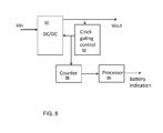
- Figure 8 shows a system of the invention.
- the capacitive DC/DC converter is shown as 90, and a feedback system 92 provides clock gating control, to provide a gated clock signal at the switching frequency fclk. This gated clock signal is provided to a counter 94 which counts the number of gated clock cycles.
- a running total is kept, but the counter may function for a fixed time interval (for example determined as a fixed number of non-gated clock pulses at the clock frequency fclk) and be reset after each time interval.
- the counter can for example be implemented as a ripple counter, such as a binary weighted ripple counter.
- a ripple counter comprises a cascade of latches.
- a 26 bit binary weighted ripple counter can count the clock cycles in a period of around 1 second for a 20 MHz clock.
- the overall count value can be processed to derive a battery level indication using processor 96. This takes account of the initial battery capacity (again in units of current x time). In this way, a warning can be provided when a battery approaches the end of its life, and/or a continuous battery level indication.
- This battery level information can be sent wirelessly from the device to a remote base unit to provide the information to a user.
- the information can be used simply to control a warning signal, for example in the form of audible beeps provided to the user.
- one area of interest for the invention is hearing aids.
- the invention can be applied to other battery operated devices where advance warning of battery usage is desirable, such as mobile phones.
- the switching frequency fclk can typically be of the order of ones or tens of MHz.
- the switching frequency is related to the capacitance value. For small internal capacitors, several tens of MHz is typical, whereas for larger external capacitors lower frequencies of operation will be used.
Priority Applications (1)
| Application Number | Priority Date | Filing Date | Title |
|---|---|---|---|
| EP12170559.4A EP2670034A1 (de) | 2012-06-01 | 2012-06-01 | Verfahren und Vorrichtung zur Eingangsstrombestimmung einer Ladungspumpe |
Applications Claiming Priority (1)
| Application Number | Priority Date | Filing Date | Title |
|---|---|---|---|
| EP12170559.4A EP2670034A1 (de) | 2012-06-01 | 2012-06-01 | Verfahren und Vorrichtung zur Eingangsstrombestimmung einer Ladungspumpe |
Publications (1)
| Publication Number | Publication Date |
|---|---|
| EP2670034A1 true EP2670034A1 (de) | 2013-12-04 |
Family
ID=46207884
Family Applications (1)
| Application Number | Title | Priority Date | Filing Date |
|---|---|---|---|
| EP12170559.4A Withdrawn EP2670034A1 (de) | 2012-06-01 | 2012-06-01 | Verfahren und Vorrichtung zur Eingangsstrombestimmung einer Ladungspumpe |
Country Status (1)
| Country | Link |
|---|---|
| EP (1) | EP2670034A1 (de) |
Cited By (2)
| Publication number | Priority date | Publication date | Assignee | Title |
|---|---|---|---|---|
| CN110024280A (zh) * | 2016-11-03 | 2019-07-16 | 思睿逻辑国际半导体有限公司 | 具有峰值电流和平均电流限制电路的可变比率电荷泵 |
| EP3686614A1 (de) * | 2019-01-23 | 2020-07-29 | Shenzhen Goodix Technology Co., Ltd. | Verfahren und vorrichtung zur messung des leistungsverbrauchs eines digitalen soc zur vorhersage der batterielebensdauer |
Citations (4)
| Publication number | Priority date | Publication date | Assignee | Title |
|---|---|---|---|---|
| US4586118A (en) * | 1984-06-05 | 1986-04-29 | The United States Of America As Represented By The United States Department Of Energy | Capacitor charging FET switcher with controller to adjust pulse width |
| US4912392A (en) * | 1986-10-18 | 1990-03-27 | Husky Computer Limited | Battery charge state monitor |
| DE4112987A1 (de) * | 1991-04-20 | 1992-10-22 | Bosch Gmbh Robert | Vorrichtung zur bestimmung des ladezustands einer wiederaufladbaren batterie |
| US5959853A (en) * | 1998-08-24 | 1999-09-28 | Kos; Marek John | Closed-loop switched capacitor network power supply |
-
2012
- 2012-06-01 EP EP12170559.4A patent/EP2670034A1/de not_active Withdrawn
Patent Citations (4)
| Publication number | Priority date | Publication date | Assignee | Title |
|---|---|---|---|---|
| US4586118A (en) * | 1984-06-05 | 1986-04-29 | The United States Of America As Represented By The United States Department Of Energy | Capacitor charging FET switcher with controller to adjust pulse width |
| US4912392A (en) * | 1986-10-18 | 1990-03-27 | Husky Computer Limited | Battery charge state monitor |
| DE4112987A1 (de) * | 1991-04-20 | 1992-10-22 | Bosch Gmbh Robert | Vorrichtung zur bestimmung des ladezustands einer wiederaufladbaren batterie |
| US5959853A (en) * | 1998-08-24 | 1999-09-28 | Kos; Marek John | Closed-loop switched capacitor network power supply |
Cited By (6)
| Publication number | Priority date | Publication date | Assignee | Title |
|---|---|---|---|---|
| CN110024280A (zh) * | 2016-11-03 | 2019-07-16 | 思睿逻辑国际半导体有限公司 | 具有峰值电流和平均电流限制电路的可变比率电荷泵 |
| CN110024280B (zh) * | 2016-11-03 | 2023-12-15 | 思睿逻辑国际半导体有限公司 | 具有峰值电流和平均电流限制电路的可变比率电荷泵 |
| EP3686614A1 (de) * | 2019-01-23 | 2020-07-29 | Shenzhen Goodix Technology Co., Ltd. | Verfahren und vorrichtung zur messung des leistungsverbrauchs eines digitalen soc zur vorhersage der batterielebensdauer |
| WO2020151846A1 (en) * | 2019-01-23 | 2020-07-30 | Shenzhen GOODIX Technology Co., Ltd. | Method and apparatus for metering power consumption of a digital soc for predicting battery life |
| CN111886508A (zh) * | 2019-01-23 | 2020-11-03 | 深圳市汇顶科技股份有限公司 | 用于量测数字SoC的功耗以预测电池寿命的方法和装置 |
| CN111886508B (zh) * | 2019-01-23 | 2023-04-18 | 深圳市汇顶科技股份有限公司 | 用于量测数字SoC的功耗以预测电池寿命的方法和装置 |
Similar Documents
| Publication | Publication Date | Title |
|---|---|---|
| US9413229B2 (en) | Low power conversion and management of energy harvesting applications | |
| EP2183656B1 (de) | Verfahren und system zum optimieren von filterkompensationskoeffizienten für ein digitales leistungsregelsystem | |
| CN101490938B (zh) | 开关模式电源系统 | |
| JP3345519B2 (ja) | 電源装置 | |
| CN111095008B (zh) | 用于电化学阻抗谱的电气架构 | |
| CN101677213B (zh) | 用于电力变换器控制器的数字峰值输入电压检测器 | |
| EP2752965B1 (de) | Schwachstrom-DC-DC-Wandler mit integriertem mit Schwachstrom-Coulomb-Zähler | |
| JP5786368B2 (ja) | 入力電圧検出回路を備えたデジタル制御スイッチング電源装置 | |
| CN104348359B (zh) | Dc-dc调节器 | |
| CN102664608A (zh) | 频率倍增器及频率倍增的方法 | |
| US20160336857A1 (en) | Switching-mode power supplies | |
| CN103001298A (zh) | 具有自适应功率管理的充电系统 | |
| KR101991366B1 (ko) | 전력 관리 장치 및 이를 이용한 멀티 소스 에너지 하베스팅 시스템 | |
| Kankanmage et al. | Supercapacitor assisted LDO (SCALDO) techniquean extra low frequency design approach to high efficiency DC-DC converters and how it compares with the classical switched capacitor converters | |
| CN110720166B (zh) | 通过多级电压转换为电池充电 | |
| US20080258686A1 (en) | Method for Detecting Removal of a Battery from a Battery Charger | |
| EP2884643A1 (de) | Gleichstrom-Gleichstromspannungswandler und -wandlungsverfahren | |
| EP2670034A1 (de) | Verfahren und Vorrichtung zur Eingangsstrombestimmung einer Ladungspumpe | |
| US8008964B1 (en) | Variable input voltage charge pump | |
| EP3116081A1 (de) | Verfahren zur steuerung der empfangenen elektrischen energie, vorrichtung zur steuerung der empfangenen elektrischen energie, elektrisches gerät | |
| US9537390B2 (en) | Control circuit, control method, DC-DC converter and electronic device | |
| WO2017144086A1 (en) | Power supply for providing an electrical pulse to an electrical consumer and a tester comprising the power supply | |
| US11372032B2 (en) | Voltage monitor using a capacitive digital-to-analog converter | |
| Subasinghage et al. | Single-input, dual polarity, dual output DC-DC converter implementation based on the SCALDO technique | |
| CN103683916A (zh) | 调整设备和调整方法 |
Legal Events
| Date | Code | Title | Description |
|---|---|---|---|
| PUAI | Public reference made under article 153(3) epc to a published international application that has entered the european phase |
Free format text: ORIGINAL CODE: 0009012 |
|
| AK | Designated contracting states |
Kind code of ref document: A1 Designated state(s): AL AT BE BG CH CY CZ DE DK EE ES FI FR GB GR HR HU IE IS IT LI LT LU LV MC MK MT NL NO PL PT RO RS SE SI SK SM TR |
|
| AX | Request for extension of the european patent |
Extension state: BA ME |
|
| STAA | Information on the status of an ep patent application or granted ep patent |
Free format text: STATUS: THE APPLICATION IS DEEMED TO BE WITHDRAWN |
|
| 18D | Application deemed to be withdrawn |
Effective date: 20140605 |