EP2670002A1 - Anschlussvorrichtungsanordnung mit Anschlussleiste - Google Patents
Anschlussvorrichtungsanordnung mit Anschlussleiste Download PDFInfo
- Publication number
- EP2670002A1 EP2670002A1 EP13168231.2A EP13168231A EP2670002A1 EP 2670002 A1 EP2670002 A1 EP 2670002A1 EP 13168231 A EP13168231 A EP 13168231A EP 2670002 A1 EP2670002 A1 EP 2670002A1
- Authority
- EP
- European Patent Office
- Prior art keywords
- contacts
- housing
- fork
- module
- blade contacts
- Prior art date
- Legal status (The legal status is an assumption and is not a legal conclusion. Google has not performed a legal analysis and makes no representation as to the accuracy of the status listed.)
- Granted
Links
Images






Classifications
-
- H—ELECTRICITY
- H01—ELECTRIC ELEMENTS
- H01R—ELECTRICALLY-CONDUCTIVE CONNECTIONS; STRUCTURAL ASSOCIATIONS OF A PLURALITY OF MUTUALLY-INSULATED ELECTRICAL CONNECTING ELEMENTS; COUPLING DEVICES; CURRENT COLLECTORS
- H01R9/00—Structural associations of a plurality of mutually-insulated electrical connecting elements, e.g. terminal strips or terminal blocks; Terminals or binding posts mounted upon a base or in a case; Bases therefor
- H01R9/22—Bases, e.g. strip, block, panel
- H01R9/24—Terminal blocks
- H01R9/26—Clip-on terminal blocks for side-by-side rail- or strip-mounting
- H01R9/2625—Clip-on terminal blocks for side-by-side rail- or strip-mounting with built-in electrical component
- H01R9/2658—Clip-on terminal blocks for side-by-side rail- or strip-mounting with built-in electrical component with built-in data-bus connection
-
- H—ELECTRICITY
- H01—ELECTRIC ELEMENTS
- H01R—ELECTRICALLY-CONDUCTIVE CONNECTIONS; STRUCTURAL ASSOCIATIONS OF A PLURALITY OF MUTUALLY-INSULATED ELECTRICAL CONNECTING ELEMENTS; COUPLING DEVICES; CURRENT COLLECTORS
- H01R9/00—Structural associations of a plurality of mutually-insulated electrical connecting elements, e.g. terminal strips or terminal blocks; Terminals or binding posts mounted upon a base or in a case; Bases therefor
- H01R9/22—Bases, e.g. strip, block, panel
- H01R9/24—Terminal blocks
- H01R9/26—Clip-on terminal blocks for side-by-side rail- or strip-mounting
- H01R9/2675—Electrical interconnections between two blocks, e.g. by means of busbars
Definitions
- the present invention relates to a terminal device assembly comprising a support rail.
- mounting rail assemblies are used, which are arranged for their protection in cabinets.
- the use of mounting rails makes it possible to quickly adapt the measuring and control electronics.
- the invention has the object to optimize this arrangement.
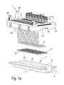
- the Fig. 1 shows in (a) a connection device arrangement according to the invention 1 with an electrical assembly 2 and a support rail 4.
- the support rail 4 is here exemplified U-shaped.
- the electrical assembly 2 has a first housing part 22, on which various electrical connections 32 (preferably as attachable connection blocks with conductor connections in, for example, push-in technology, ringan gleichtechnik, IDC technology, tension spring technology or the like.). Formed for connecting electrical conductors (not shown) may be formed
- connection strip 31 is provided for connection of connected electrical assemblies, which will be described in more detail below.
- the assembly 2 is designed like a module and preferably removable and thus exchangeable to the mounting rail 4 fastened so that it can be used as a standalone assembly or in a terminal clamping arrangement or in a series of assemblies 2.
- the first housing part 22 has a housing lower side 21 on its side facing the mounting rail 4, and a housing upper side 26 on its side 24 facing away from the mounting rail 4.
- the assembly is preferably suitable for snapping onto a mounting rail, but can also be arranged on a different base such as a bottom plate. Preferably, it is designed to be stackable.
- a plurality of heat pipes 5 can be carried out until they rest partially on the support rail 4 facing the housing bottom 23.
- the heat pipes 5 are L-shaped here.
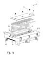
- a groove 211 is provided on the housing bottom 23 for each heat pipe 5, in which the heat pipe 5 can be inserted.
- thermally conductive plate 6 can be arranged optionally, which is made here of aluminum.
- the plate 6 extends in an extension direction 8 of the mounting rail. It also has for each heat pipe 5 a groove 61 into which the respective heat pipe 5 can be inserted.
- the heat pipes 5 and the plate 6 are at least partially on legs 41 of the support rail 4, so that the support rail 4 is used to dissipate heat. This also opens up well Fig. 4 ,
- fastening means For fastening the plate 6 to the housing bottom 23 screws 7 are provided here as fastening means. But there are also other fasteners (not shown) such as snaps, rivets or similar usable.
- each heat pipe 5 is provided here for one assembly module 332 in each case.
- the module modules 332 each have a second housing part 331 (s. Fig. 3 (a) ) and can be arranged individually or grouped in a housing pocket 27 of the first housing part 22 on this.
- the module modules 331 are inserted individually or jointly into an insertion direction 9, which extends transversely to the extension direction 8 of the support rail 4, into its housing pocket 27.
- a part of a heat pipe 5 is inserted into an assembly module 332.
- a plurality of heat pipes 5 are provided for a module module 332.
- one or more heat pipes 5 are lined up together with their assembly module 332 to each other.
- each module module 332 for attachment to the first housing part 22 includes a mounting rod 336 which extends in the insertion direction 9, at one end as an actuating means 335 a knob and at the other end as a fastening means 334 T-shaped Anformung formed is.
- the Anformung 334 is inserted through a recess 25 in the upper housing side 26 of the first housing part 22 and rotated by turning the knob 335 so that the Anformung 334 is no longer retractable through the recess 25.
- a screwdriver (not shown) can be used for actuating the rotary knob 335.
- a through hole 33 is also provided in the mounting rod 336, on the side of each of which a sensor part of a light barrier 337 is arranged.
- the light barrier 337 is interrupted.
- the through hole 333 becomes so twisted that a light (not shown) of the light barrier 337 through the through hole 33 can pass from a sensor part of the light barrier 337 to the other sensor part of the light barrier 337, so that the light barrier 337 is closed.
- a signal (not shown) of the light barrier 337 is usable by the module module 332, for example by the electronics (not shown) of the module module 332 is activated only when the light barrier 337 is closed and therefore the module module 332 is attached to the first housing part 22. Or a supply voltage of the electronics is interrupted when the light barrier 337 is interrupted. In this case, an electrical connection of the electronics with the light barrier 337 by means of mechanical or electrical means (not shown) can be realized.
- the terminal block 31 is provided with a plurality of in a row alternately juxtaposed fork contacts 31 a and blade contacts 31 b.
- a blade contact 31 b provided, which is here simply designed as a sheet metal stamping, then a fork contact 31 a (a kind of connection box as Blechstanz- / bending part), then again a blade contact 31 b, etc.
- the fork and blade contacts 31 a, b are used here in a compact arrangement alternately in corresponding chambers 31 c of a housing 31 d.
- a printed circuit board 22a - each one of the terminal strips 31 is arranged.
- solder pins 31 e which are connected to, for example, the plate 22 a (which may also be a part of a housing 22) (see also for illustrative purposes) Fig. 8 ) and which are formed integrally with the contacts 31 a, b, the connection to an electronics or the like.
- the terminal block 31 d could also be attached to a printed circuit board in another technique (SMD or the like) or otherwise (latched or screwed) to another part of a housing 22.
- each preferably one of the terminal strips 31 is arranged or formed, in such a way that in the aligned state, the fork and blade contacts 31 a, b adjacent assemblies 2 each interlock and contact each other.
- 31 more contacts per unit length can be arranged side by side by the in the row of contacts 31 a, b alternating arrangement of the fork and blade contacts 31 a, b in the terminal block 31 as in the classical arrangement in which on one side of the module or a housing 22 (here on a printed circuit board or other plate 22a as part of the housing), the fork contacts 31 a and on the other side the blade contacts 31 b (this arrangement is not shown here) are arranged , since in this arrangement, the ranking requires only more fork widths width than the alternate arrangement.
- the terminal block Preferably, only a single row of the fork and blade contacts 31 a, b is provided per terminal block. But it could also be two or more rows of terminals over each other / provided, in which case preferably in Each of the rows, the terminal contacts alternately as fork or blade contacts 31 a, b would be formed.
- bus contacts there are thus many bus contacts in a small space can be arranged, so in Fig. 5 Exemplary 18 contacts in a rather short bar.
- the fork and blade contacts 31 a, b can serve as bus contacts that are used to pass on energy and / or signals / data from module 2 to module 2.
- the assembly is carried out in a manner not shown here, the transfer and possibly processing of the energy and / or the signals / data. It can thus after Fig. 5 to 7 especially many bus cables from module to module 2 are passed on in a small space.
Landscapes
- Connections Arranged To Contact A Plurality Of Conductors (AREA)
Abstract
Description
- Die vorliegende Erfindung betrifft eine Anschlussvorrichtungsanordnung, die eine Tragschiene umfasst.
- Für die Mess- und Steuerungselektroniken in der Fertigungstechnik werden Tragschienenanordnungen verwendet, die zu ihrem Schutz in Schaltschränken angeordnet sind. Die Verwendung von Tragschienen ermöglicht eine schnelle Anpassung der Mess- und Steuerungselektroniken.
- Zur Weiterleitung von Energie und Daten/Signalen von Baugruppe zu Baugruppe werden oftmals Gabel- und Messerkontakte verwendet, die zusammensteckbar sind und die als Buskontakte dienen.
- Die Erfindung hat die Aufgabe, diese Anordnung zu optimieren.
- Die Aufgabe wird durch die Merkmale des Patentanspruchs 1 gelöst. Weitere vorteilhafte Ausgestaltungen der Erfindung sind den Unteransprüchen zu entnehmen.
- Nachfolgend wird die Erfindung unter Bezug auf die Figuren näher beschrieben. Die Figuren sind lediglich beispielhaft und schränken den allgemeinen Erfindungsgedanken nicht ein. Es zeigen:
- Fig. 1
- in
Fig. 1(a) eine erfindungsgemäße Anschlussvorrichtungsanordnung mit einer elektrischen Baugruppe und einer Tragschiene in einer Explosionsdarstellung von einer Oberseite, inFig. 1(b) die Anordnung ohne die Tragschiene in Explosionsdarstellung von der Unterseite, inFig. 1 (c) die teilmontierte Anordnung ohne die Tragschiene in Explosionsdarstellung von der Unterseite, und inFig. 1 (d) die montierte Anordnung ohne die Tragschiene in Explosionsdarstellung von der Unterseite; - Fig. 2
- in
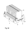
Fig. 2(a) - (d) die Anschlussvorrichtungsanordnung derFig. 1 ohne die Tragschiene in einer perspektivischen Ansicht jeweils von oben, wobei die DarstellungenFig. 2(b) - (d) das Anordnen von Baugruppenmodulen an die Anschlussvorrichtungsanordnung zeigt; - Fig. 3
- die Anschlussvorrichtungsanordnung der
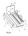
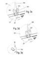
Fig. 2 ohne die Tragschiene in einer perspektivischen Ansicht von oben, wobei die DarstellungenFig. 3(a) - (b) das Anordnen eines zweiten Gehäuseteils eines Baugruppenmoduls zeigen, wobei die DarstellungenFig. 3(c) - (d) jeweils einen Ausschnitt aus derFig. 3(b) zeigen, wobei dieFig. 3(g) eine Gehäuseoberseite des ersten Gehäuseteils von unten zeigt, und wobei dieFig. 3(e) - (f) jeweils einen Ausschnitt ausFig. 3(g) zeigen; und - Fig. 4
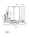
- die Anschlussvorrichtungsanordnung der
Fig. 2 mit Elektronik und Anschlussblöcken auf einer Tragschiene; - Fig. 5-7
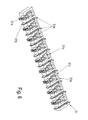
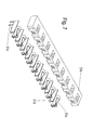
- eine Anschlussleiste, in
Fig. 5 und6 in verschiedener perspektivischer Ansicht und inFig. 7 in Sprengansicht; - Fig. 8
- eine Gehäuseplatte oder Leiterplatte mit zwei Anschlussleisten in Anreihrichtung.
- Die
Fig. 1 zeigt in (a) eine erfindungsgemäße Anschlussvorrichtungsanordnung 1 mit einer elektrischen Baugruppe 2 und einer Tragschiene 4. Die Tragschiene 4 ist hier beispielhaft u- förmig ausgebildet. - Die elektrische Baugruppe 2 weist ein erstes Gehäuseteil 22 auf, an dem verschiedene elektrische Anschlüsse 32 (vorzugsweise als aufsetzbare Anschlussblöcke mit Leiteranschlüssen in beispielsweise Push-In-Technik, Schraubanschlusstechnik, IDC-Technik, Zugfedertechnik oder dgl. ausgebildet.) zum Anschließen elektrischen Leiter (nicht dargestellt) ausgebildet sein können
- Es ist ferner eine Anschlussleiste 31 zum Anschluss angereihter elektrischer Baugruppen vorgesehen, die weiter untern noch näher beschrieben wird.
- Die Baugruppe 2 ist modulartig ausgestaltet und vorzugsweise abnehmbar und somit austauschbar an der Tragschiene 4 befestigbar, so dass sie als allein stehende Baugruppe oder auch in einer Reihenklemmanordnung oder in einer Reihung von Baugruppen 2 nutzbar ist.
- Das erste Gehäuseteil 22 weist eine Gehäuseunterseite 21 an seiner der Tragschiene 4 zugewandten Seite 23 und eine Gehäuseoberseite 26 an ihrer der Tragschiene 4 abgewandten Seite 24.
- Die Baugruppe eignet sich vorzugsweise zum Aufrasten auf eine Tragschiene, kann aber auch auf einer anderen Basis wie einer Bodenplatte angeordnet werden. Vorzugsweise ist sie anreihbar ausgelegt.
- Durch Durchgangsöffnungen 28 im ersten Gehäuseteil 22 sind mehrere Wärmerohre 5 durchführbar, bis sie teilweise an der der Tragschiene 4 zugewandten Gehäuseunterseite 23 anliegen. Dafür sind die Wärmerohre 5 hier L-förmig ausgebildet. In
Fig. 1 (b) ist sichtbar, dass an der Gehäuseunterseite 23 für jedes Wärmerohr 5 eine Nut 211 vorgesehen ist, in die das Wärmerohr 5 einlegbar ist. - Zwischen der Tragschiene 4 und den an der Gehäuseunterseite 23 anliegenden Teilen der Wärmerohre 5 ist eine wärmeleitfähige Platte 6 optional anordbar, die hier aus Aluminium gefertigt ist. Die Platte 6 erstreckt sich in eine Erstreckungsrichtung 8 der Tragschiene. Sie weist ebenfalls für jedes Wärmerohr 5 eine Nut 61 auf, in die das jeweilige Wärmerohr 5 einlegbar ist. In einem montierten Zustand liegen die Wärmerohre 5 und die Platte 6 zumindest teilweise auf Schenkeln 41 der Tragschiene 4 auf, so dass die Tragschiene 4 zum Abführen von Wärme mitgenutzt wird. Dies erschließt sich auch gut aus
Fig. 4 . - Zum Befestigen der Platte 6 an der Gehäuseunterseite 23 sind hier als Befestigungsmittel 7 Schrauben vorgesehen. Es sind aber auch andere Befestigungsmittel (nicht dargestellt) wie Schnappverschlüsse, Nieten oder ähnlich verwendbar.
- In
Fig. 2 ist gezeigt, dass hier jedes Wärmerohr 5 für jeweils ein Baugruppenmodul 332 vorgesehen ist. Die Baugruppenmodule 332 weisen jeweils ein zweites Gehäuseteil 331 (s.Fig. 3(a) ) auf und sind einzeln oder gruppiert in eine Gehäusetasche 27 des ersten Gehäuseteils 22 an dieses anordbar. Dafür werden die Baugruppenmodule 331 jeweils einzeln oder gemeinsam in eine Einschubrichtung 9, die sich quer zur Erstreckungsrichtung 8 der Tragschiene 4 erstreckt, in ihre Gehäusetasche 27 eingeschoben. Dabei wird jeweils ein Teil eines Wärmerohres 5 in ein Baugruppenmodul 332 eingeschoben. Es sind aber auch Ausführungsformen denkbar, bei denen mehrere Wärmerohre 5 für ein Baugruppenmodul 332 vorgesehen sind. Zudem sind auch Ausführungsformen denkbar, bei denen ein oder mehrere Wärmerohre 5 gemeinsam mit ihrem Baugruppenmodul 332 aneinander gereiht werden. - In der
Fig. 3 ist sichtbar, das jedes Baugruppenmodul 332 zur Befestigung an dem ersten Gehäuseteil 22 eine Befestigungsstange 336 umfasst, die sich in die Einschubrichtung 9 erstreckt, an deren einem Ende als Betätigungsmittel 335 ein Drehknopf und an deren anderem Ende als Befestigungsmittel 334 eine T-förmige Anformung ausgebildet ist. Beim Einschieben eines Baugruppenmodul 332 in seine Gehäusetasche 27 wird die Anformung 334 durch eine Ausnehmung 25 in der Gehäuseoberseite 26 des ersten Gehäuseteils 22 gesteckt und durch Drehen am Drehknopf 335 so verdreht, dass die Anformung 334 nicht mehr durch die Ausnehmung 25 zurückschiebbar ist. Zum Betätigen des Drehknopfes 335 ist beispielsweise ein Schraubendreher (nicht dargestellt) verwendbar. - In der hier gezeigten Ausführungsform ist zudem in der Befestigungsstange 336 eine Durchgangsbohrung 33 vorgesehen, an deren Seite jeweils ein Sensorteil einer Lichtschranke 337 angeordnet ist. Solange das Baugruppenmodul 332 noch nicht am ersten Gehäuseteil 22 befestigt ist, ist die Lichtschranke 337 unterbrochen. Durch Verdrehen der Befestigungsstange 336 wird die Durchgangsbohrung 333 so verdreht, dass ein Licht (nicht dargestellt) der Lichtschranke 337 durch die Durchgangsbohrung 33 hindurch von einem Sensorteil der Lichtschranke 337 zum anderen Sensorteil der Lichtschranke 337 gelangen kann, so dass die Lichtschranke 337 geschlossen ist. Ein Signal (nicht dargestellt) der Lichtschranke 337 ist von dem Baugruppenmodul 332 verwendbar, beispielsweise indem die Elektronik (nicht dargestellt) des Baugruppenmoduls 332 erst aktiviert ist, wenn die Lichtschranke 337 geschlossen und daher das Baugruppenmodul 332 am ersten Gehäuseteil 22 befestigt ist. Oder eine Versorgungsspannung der Elektronik ist unterbrochen, wenn die Lichtschranke 337 unterbrochen ist. Dabei ist eine elektrische Verbindung der Elektronik mit der Lichtschranke 337 mittels mechanischen oder elektrischen Mitteln (nicht dargestellt) realisierbar.
- Nachfolgend sei auf der Basis der
Fig. 5 - 7 näher die Anschlussleiste 31 betrachtet. - Die Anschlussleiste 31 ist mit einer Mehrzahl von in einer Reihe abwechselnd nebeneinander angeordneten Gabelkontakten 31 a und Messerkontakten 31 b versehen.
- Beispielhaft ist in
Fig. 5 links zunächst ein Messerkontakt 31 b vorgesehen, der hier einfach als Blechstanzteil ausgebildet ist, dann ein Gabelkontakt 31 a (eine Art Anschlusstulpe als Blechstanz-/Biegeteil), dann wieder ein Messerkontakt 31 b, usw. - Die Gabel- und Messerkontakte 31 a, b sind hier in kompakter Anordnung abwechselnd in entsprechende Kammern 31 c eines Gehäuses 31 d eingesetzt. An jedem der beiden Enden des Gehäuses 22 - hier an einer Platte 22a, vorzugsweise einer Leiterplatte 22a - ist je eine der Anschlussleisten 31 angeordnet. Vorzugsweise an Lötstiften 31 e, die zum Beispiel mit der Platte 22a (die auch ein Teil eines Gehäuses 22 sein kann) verbunden werden (siehe zur Veranschaulichung auch
Fig. 8 ) und die einstückig mit den Kontakten 31 a, b ausgebildet sind, erfolgt der Anschluss an eine Elektronik oder dgl. in der Baugruppe. Die Anschlussleiste 31 d könnte auch in anderer Technik (SMD oder dgl.) an einer Leiterplatte befestigt sein oder auf andere Art (rastend oder geschraubt) an einem anderen Teil eines Gehäuses 22. - Es ist vorzugsweise eine gerade Zahl an Gabel- und Messerkontakten 31 a, b vorgesehen.
- Dabei ist in Erstreckungsrichtung der Tragschiene - bezogen auf den auf die Tragschiene aufgesetzten Zustand - an jedem der beiden Enden der elektrischen Baugruppe - hier an deren Gehäuse an der Leiterplatte 22a jeweils vorzugsweise jeweils eine der Anschlussleisten 31 angeordnet bzw. ausgebildet, und zwar derart, dass im angereihten Zustand die Gabel- und Messerkontakte 31 a, b benachbarter Baugruppen 2 jeweils ineinander greifen und einander kontaktieren.
- Vorteilhaft ist, dass durch die in der Reihe der Kontakte 31 a, b abwechselnde Anordnung der Gabel- und Messerkontakte 31 a, b in der Anschlussleiste 31 mehr Kontakte pro Längeneinheit (z.B. je 10 cm Länge) nebeneinander angeordnet werden können als bei der klassischen Anordnung, bei welcher auf einer Seite der Baugruppe bzw. eines Gehäuses 22 (hier an einer Leiterplatte oder sonstigen Platte 22a als Teil des Gehäuses) die Gabelkontakte 31 a und auf der andere Seite die Messerkontakte 31 b (diese Anordnung ist hier nicht dargestellt) angeordnet sind, da bei dieser Anordnung die Reihung nur aus Gabelkontakten mehr Baubreite erfordert als die abwechselnde Anordnung.
- Es ist auch denkbar, nur einen Teil der Kontakte 31 a, b derart abwechselnd anzuordnen und einen Teil nicht. Bevorzugt wird aber die wechselnde Anordnung über die gesamte Länge der Reihung bzw. der Anschlussleiste hinweg, da derart eine einzige Art von Anschlussleisten an beiden Enden des Gehäuses 22 verwendet werden kann, was vorteilhaft ist.
- Würden je Leiste nur Gabel- oder nur Messerkontakte 31 a. b verbaut oder wäre keine vollständige abwechselnde Anordnung gegeben, würden an den beiden Enden der Baugruppe immer noch verschiedene Anschlussleisten zum Einsatz kommen müssen.
- Vorzugsweise ist nur eine einzige Reihe der Gabel- und Messerkontakte 31 a, b je Anschlussleiste vorgesehen. Es könnten aber auch zwei oder mehr Reihen von Anschlusskontakten übereinander /vorgesehen sein, wobei dann vorzugsweise in jeder der Reihen die Anschlusskontakte abwechselnd als Gabel- oder Messerkontakte 31 a, b ausgebildet wären.
- Es sind somit besonders viele Buskontakte auf engem Raum anordbar, so in
Fig. 5 beispielhaft 18 Kontakte in einer recht kurzen Leiste. - Die Gabel- und Messerkontakte 31 a, b können als Buskontakte dienen, die der Weitergabe von Energie und/oder Signalen/Daten von Baugruppe 2 zu Baugruppe 2 verwendet werden. Innerhalb der Baugruppe erfolgt in hier nicht dargestellter Weise die Weitergabe und ggf. Verarbeitung der Energie und/oder der Signale/Daten. Es können somit nach
Fig. 5 bis 7 besonders viele Busleitungen von baugruppe zu Baugruppe 2 auf engem Raum weitergegeben werden. -
- 1
- Anschlussvorrichtungsanordnung
- 2
- elektrische Baugruppe
- 21
- Gehäuseunterseite
- 22
- Erstes Gehäuseteil
- 23
- der Tragschiene zugewandte Seite
- 24
- der Tragschiene abgewandte Seite
- 25
- Ausnehmung
- 26
- Gehäuseoberseite
- 27
- Gehäusetaschen
- 28
- Durchgangsöffnungen
- 31
- Anschlussleiste
- 31a, b
- Gabel- und Messerkontakte
- 31c
- Kammern
- 31d
- Gehäuse
- 31e
- Stifte
- 32
- elektrische Anschlüsse
- 331
- Zweites Gehäuseteil
- 332
- Baugruppenmodul
- 333
- Durchgangsbohrung
- 334
- Befestigungsmittel, Anformung
- 335
- Betätigungsmittel, Drehknopf
- 336
- Verbindungsstange
- 337
- Lichtschranke
- 33
- Anschluss-, Mess- und/oder Steuerungselektronik
- 4
- Tragschiene
- 5
- Wärmerohr
- 6
- Wärmeleitfähige Platte
- 61
- Aufnahmenut für das Wärmerohr
- 7
- Befestigungsmittel, Schrauben
- 8
- Erstreckungsrichtung der Tragschiene
- 9
- Einschubrichtung der Baugruppenmodule
Claims (5)
- Anreihbare elektrische Baugruppe (2), die elektrische Anschlüsse (32) und eine Anschluss-, Mess- und/oder Steuerungselektronik (33) umfasst, und die vorzugsweise auf Tragschiene (4) aufsetzbar ist, und die in Anreihrichtung Buskontakte aufweist, um Energie- und/oder Signale/Daten von Baugruppe zu Baugruppe weiterzuleiten, wobei mehrere der Buskontakte (31 a, b) in einer Reihe angeordnet sind, und wobei die Buskontakte Gabel- und Messerkontakte aufweisen, dadurch gekennzeichnet, dass die Gabel- und Messerkontakte (31 a, b) in einer Reihe abwechselnd nebeneinander angeordnet sind.
- Anreihbare elektrische Baugruppe (2) nach Anspruch 1, dadurch gekennzeichnet, dass die Gabel- und Messerkontakte (31 a, b) abwechselnd in Kammern (31 c) eines leistenförmigen Gehäuses (31 d) eingesetzt sind und dass sie mit dem Gehäuse eine Anschlussleiste (31) auszubilden.
- Anreihbare elektrische Baugruppe (2) nach Anspruch 2, dadurch gekennzeichnet, dass in jeder Anschlussleiste (31) eine gerade Anzahl an Gabel- und Messerkontakten (31 a, b) vorgesehen ist.
- Anreihbare elektrische Baugruppe (2) nach Anspruch 1, 2 oder 3, dadurch gekennzeichnet, dass an jedem der beiden Enden der elektrischen Baugruppe - hier an ihrem Gehäuse (22) - jeweils eine der Anschlussleisten (31) angeordnet bzw. ausgebildet ist, derart, dass im angereihten Zustand die Gabel- und Messerkontakte (31 a, b) benachbarter aneinander gereihter Baugruppen (2) jeweils ineinander greifen und einander kontaktieren.
- Anschlussvorrichtungsanordnung (1) nach einem der vorstehenden Ansprüche, dadurch gekennzeichnet, dass ein Wärmerohr (5) zumindest teilweise an einer der Tragschiene (4) zugewandten Seite (23) der elektrischen Baugruppe (2) angeordnet ist.
Applications Claiming Priority (1)
| Application Number | Priority Date | Filing Date | Title |
|---|---|---|---|
| DE202012102012U DE202012102012U1 (de) | 2012-06-01 | 2012-06-01 | Anschlussvorrichtungsanordnung mit Anschlussleiste |
Publications (2)
| Publication Number | Publication Date |
|---|---|
| EP2670002A1 true EP2670002A1 (de) | 2013-12-04 |
| EP2670002B1 EP2670002B1 (de) | 2019-08-14 |
Family
ID=48463799
Family Applications (1)
| Application Number | Title | Priority Date | Filing Date |
|---|---|---|---|
| EP13168231.2A Active EP2670002B1 (de) | 2012-06-01 | 2013-05-17 | Anschlussvorrichtungsanordnung mit Anschlussleiste |
Country Status (2)
| Country | Link |
|---|---|
| EP (1) | EP2670002B1 (de) |
| DE (1) | DE202012102012U1 (de) |
Citations (4)
| Publication number | Priority date | Publication date | Assignee | Title |
|---|---|---|---|---|
| DE20013435U1 (de) * | 2000-08-04 | 2001-12-13 | Weidmüller Interface GmbH & Co., 32760 Detmold | Anschlußklemme für Leiterplatten |
| EP1258957A1 (de) * | 2001-05-16 | 2002-11-20 | Gustav Hensel GmbH & Co. KG | Schaltgerätesystem |
| DE202010004408U1 (de) * | 2009-12-10 | 2011-04-21 | Weidmüller Interface GmbH & Co. KG | Reihung von Anschlussmodulen |
| DE202011000834U1 (de) * | 2010-06-29 | 2011-11-08 | Weidmüller Interface GmbH & Co. KG | Busfähiges Anschluss- und/oder Funktionsmodul und Anschlusssystem mit derartigen Modulen |
Family Cites Families (5)
| Publication number | Priority date | Publication date | Assignee | Title |
|---|---|---|---|---|
| DE3206324C2 (de) * | 1982-02-22 | 1985-08-29 | Siemens AG, 1000 Berlin und 8000 München | Anschlußanordnung für Signalleitungen |
| DE20108460U1 (de) * | 2001-05-19 | 2001-10-25 | Wieland Electric GmbH, 96052 Bamberg | Modulares Bausatzsystem für eine streckbare elektrische Anschlussvorrichtung und elektrische Anschlussvorrichtung |
| DE202006013674U1 (de) * | 2006-09-06 | 2006-11-02 | Abb Patent Gmbh | Hoch-, Mittel- oder Niederspannungsschaltschrank |
| DE202010006065U1 (de) * | 2010-04-23 | 2010-08-05 | VIPA Gesellschaft für Visualisierung und Prozeßautomatisierung m.b.H. | Sequentiell aufbaubarer, modularer Bus für ein Automatisierungs- oder Steuerungssystem |
| DE102011051154A1 (de) * | 2010-08-02 | 2012-02-02 | Weidmüller Interface GmbH & Co. KG | Busfähiges Anschluss- und/oder Funktionsmodul und Anschlusssystem mit derartigen Modulen |
-
2012
- 2012-06-01 DE DE202012102012U patent/DE202012102012U1/de not_active Expired - Lifetime
-
2013
- 2013-05-17 EP EP13168231.2A patent/EP2670002B1/de active Active
Patent Citations (4)
| Publication number | Priority date | Publication date | Assignee | Title |
|---|---|---|---|---|
| DE20013435U1 (de) * | 2000-08-04 | 2001-12-13 | Weidmüller Interface GmbH & Co., 32760 Detmold | Anschlußklemme für Leiterplatten |
| EP1258957A1 (de) * | 2001-05-16 | 2002-11-20 | Gustav Hensel GmbH & Co. KG | Schaltgerätesystem |
| DE202010004408U1 (de) * | 2009-12-10 | 2011-04-21 | Weidmüller Interface GmbH & Co. KG | Reihung von Anschlussmodulen |
| DE202011000834U1 (de) * | 2010-06-29 | 2011-11-08 | Weidmüller Interface GmbH & Co. KG | Busfähiges Anschluss- und/oder Funktionsmodul und Anschlusssystem mit derartigen Modulen |
Also Published As
| Publication number | Publication date |
|---|---|
| EP2670002B1 (de) | 2019-08-14 |
| DE202012102012U1 (de) | 2013-09-09 |
Similar Documents
| Publication | Publication Date | Title |
|---|---|---|
| EP3028345B1 (de) | Kontaktelement für eine steckanordnung eines insbesondere aussen geführten bussystems | |
| EP2593991B1 (de) | Elektrisches kontaktteil | |
| EP2915215B1 (de) | Reihenbausteinanordnung mit einem energiebussystem | |
| EP2456011B1 (de) | Elektrisches Klemmenbauelement | |
| EP1811604B1 (de) | Elektrischer Reihenklemmenblock | |
| DE10351289B4 (de) | Steckbrücke für elektrische Anschluß- und/oder Verbindungsklemmen | |
| EP3111515B1 (de) | Reihenklemme und reihenklemmenblock | |
| DE202010004408U1 (de) | Reihung von Anschlussmodulen | |
| DE102019102011A1 (de) | Kontakt- und Busschienenanordnung | |
| EP2393160B1 (de) | Rangierklemme in Etagenbauform | |
| DE102006031129B4 (de) | Gerätesystem mit auf einer Tragschiene montierten elektrischen Gerätemodulen und in der Tragschine angeordneter BUS-Leitung | |
| WO2012109683A1 (de) | Vorrichtung zum verbinden und kontaktieren zumindest einer led-einheit, sowie led-einheit und leuchtsystem | |
| DE102009049489A1 (de) | Anschlussklemme und Elektroinstallationsgerät mit einer Anschlussklemme | |
| DE102012020219B4 (de) | Vorrichtung zum Kontaktieren von elektrischen Leitern und/oder elektrischen Kontaktelementen, sowie Leuchte oder elektrisches Gerät | |
| DE102017116342A1 (de) | Leiterplattenanordnung mit einer Kontaktvorrichtung zur leitenden Verbindung der Leiterplatten der Leiterplattenanordnung nach Art eines Bussystems | |
| DE102014116811A1 (de) | Reihenklemme | |
| DE102008025433A1 (de) | Klemmenanschlußblock | |
| EP2095469A1 (de) | Montagevorrichtung zur aufnahme von elektronikmodulen | |
| EP2270821B1 (de) | Windenergieanlage mit einem Umrichter und wenigstens einem Hochleistungswiderstand | |
| DE102008020503A1 (de) | Erdungsanschlusselement | |
| DE102015110223B4 (de) | Baugruppe einer Klemmeneinrichtung zum Anschließen von elektrischen Leitern | |
| DE102011052964B4 (de) | Elektrisches Kontaktelement zur Querrangierung zwischen E/A-Modulen | |
| EP2670002B1 (de) | Anschlussvorrichtungsanordnung mit Anschlussleiste | |
| DE202010008559U1 (de) | Sammelanschlussleiste | |
| DE102010045973B4 (de) | Vorrichtung zur Überwachung von Strömen |
Legal Events
| Date | Code | Title | Description |
|---|---|---|---|
| PUAI | Public reference made under article 153(3) epc to a published international application that has entered the european phase |
Free format text: ORIGINAL CODE: 0009012 |
|
| AK | Designated contracting states |
Kind code of ref document: A1 Designated state(s): AL AT BE BG CH CY CZ DE DK EE ES FI FR GB GR HR HU IE IS IT LI LT LU LV MC MK MT NL NO PL PT RO RS SE SI SK SM TR |
|
| AX | Request for extension of the european patent |
Extension state: BA ME |
|
| 17P | Request for examination filed |
Effective date: 20140319 |
|
| RBV | Designated contracting states (corrected) |
Designated state(s): AL AT BE BG CH CY CZ DE DK EE ES FI FR GB GR HR HU IE IS IT LI LT LU LV MC MK MT NL NO PL PT RO RS SE SI SK SM TR |
|
| STAA | Information on the status of an ep patent application or granted ep patent |
Free format text: STATUS: EXAMINATION IS IN PROGRESS |
|
| 17Q | First examination report despatched |
Effective date: 20171109 |
|
| GRAP | Despatch of communication of intention to grant a patent |
Free format text: ORIGINAL CODE: EPIDOSNIGR1 |
|
| STAA | Information on the status of an ep patent application or granted ep patent |
Free format text: STATUS: GRANT OF PATENT IS INTENDED |
|
| INTG | Intention to grant announced |
Effective date: 20190418 |
|
| GRAS | Grant fee paid |
Free format text: ORIGINAL CODE: EPIDOSNIGR3 |
|
| GRAA | (expected) grant |
Free format text: ORIGINAL CODE: 0009210 |
|
| STAA | Information on the status of an ep patent application or granted ep patent |
Free format text: STATUS: THE PATENT HAS BEEN GRANTED |
|
| AK | Designated contracting states |
Kind code of ref document: B1 Designated state(s): AL AT BE BG CH CY CZ DE DK EE ES FI FR GB GR HR HU IE IS IT LI LT LU LV MC MK MT NL NO PL PT RO RS SE SI SK SM TR |
|
| REG | Reference to a national code |
Ref country code: GB Ref legal event code: FG4D Free format text: NOT ENGLISH |
|
| REG | Reference to a national code |
Ref country code: CH Ref legal event code: EP Ref country code: AT Ref legal event code: REF Ref document number: 1168121 Country of ref document: AT Kind code of ref document: T Effective date: 20190815 |
|
| RAP2 | Party data changed (patent owner data changed or rights of a patent transferred) |
Owner name: WEIDMUELLER INTERFACE GMBH & CO. KG |
|
| REG | Reference to a national code |
Ref country code: IE Ref legal event code: FG4D Free format text: LANGUAGE OF EP DOCUMENT: GERMAN |
|
| REG | Reference to a national code |
Ref country code: DE Ref legal event code: R096 Ref document number: 502013013351 Country of ref document: DE |
|
| REG | Reference to a national code |
Ref country code: NL Ref legal event code: MP Effective date: 20190814 |
|
| REG | Reference to a national code |
Ref country code: LT Ref legal event code: MG4D |
|
| PG25 | Lapsed in a contracting state [announced via postgrant information from national office to epo] |
Ref country code: NO Free format text: LAPSE BECAUSE OF FAILURE TO SUBMIT A TRANSLATION OF THE DESCRIPTION OR TO PAY THE FEE WITHIN THE PRESCRIBED TIME-LIMIT Effective date: 20191114 Ref country code: SE Free format text: LAPSE BECAUSE OF FAILURE TO SUBMIT A TRANSLATION OF THE DESCRIPTION OR TO PAY THE FEE WITHIN THE PRESCRIBED TIME-LIMIT Effective date: 20190814 Ref country code: BG Free format text: LAPSE BECAUSE OF FAILURE TO SUBMIT A TRANSLATION OF THE DESCRIPTION OR TO PAY THE FEE WITHIN THE PRESCRIBED TIME-LIMIT Effective date: 20191114 Ref country code: NL Free format text: LAPSE BECAUSE OF FAILURE TO SUBMIT A TRANSLATION OF THE DESCRIPTION OR TO PAY THE FEE WITHIN THE PRESCRIBED TIME-LIMIT Effective date: 20190814 Ref country code: HR Free format text: LAPSE BECAUSE OF FAILURE TO SUBMIT A TRANSLATION OF THE DESCRIPTION OR TO PAY THE FEE WITHIN THE PRESCRIBED TIME-LIMIT Effective date: 20190814 Ref country code: LT Free format text: LAPSE BECAUSE OF FAILURE TO SUBMIT A TRANSLATION OF THE DESCRIPTION OR TO PAY THE FEE WITHIN THE PRESCRIBED TIME-LIMIT Effective date: 20190814 Ref country code: PT Free format text: LAPSE BECAUSE OF FAILURE TO SUBMIT A TRANSLATION OF THE DESCRIPTION OR TO PAY THE FEE WITHIN THE PRESCRIBED TIME-LIMIT Effective date: 20191216 Ref country code: FI Free format text: LAPSE BECAUSE OF FAILURE TO SUBMIT A TRANSLATION OF THE DESCRIPTION OR TO PAY THE FEE WITHIN THE PRESCRIBED TIME-LIMIT Effective date: 20190814 |
|
| PG25 | Lapsed in a contracting state [announced via postgrant information from national office to epo] |
Ref country code: AL Free format text: LAPSE BECAUSE OF FAILURE TO SUBMIT A TRANSLATION OF THE DESCRIPTION OR TO PAY THE FEE WITHIN THE PRESCRIBED TIME-LIMIT Effective date: 20190814 Ref country code: LV Free format text: LAPSE BECAUSE OF FAILURE TO SUBMIT A TRANSLATION OF THE DESCRIPTION OR TO PAY THE FEE WITHIN THE PRESCRIBED TIME-LIMIT Effective date: 20190814 Ref country code: ES Free format text: LAPSE BECAUSE OF FAILURE TO SUBMIT A TRANSLATION OF THE DESCRIPTION OR TO PAY THE FEE WITHIN THE PRESCRIBED TIME-LIMIT Effective date: 20190814 Ref country code: RS Free format text: LAPSE BECAUSE OF FAILURE TO SUBMIT A TRANSLATION OF THE DESCRIPTION OR TO PAY THE FEE WITHIN THE PRESCRIBED TIME-LIMIT Effective date: 20190814 Ref country code: IS Free format text: LAPSE BECAUSE OF FAILURE TO SUBMIT A TRANSLATION OF THE DESCRIPTION OR TO PAY THE FEE WITHIN THE PRESCRIBED TIME-LIMIT Effective date: 20191214 Ref country code: GR Free format text: LAPSE BECAUSE OF FAILURE TO SUBMIT A TRANSLATION OF THE DESCRIPTION OR TO PAY THE FEE WITHIN THE PRESCRIBED TIME-LIMIT Effective date: 20191115 |
|
| PG25 | Lapsed in a contracting state [announced via postgrant information from national office to epo] |
Ref country code: TR Free format text: LAPSE BECAUSE OF FAILURE TO SUBMIT A TRANSLATION OF THE DESCRIPTION OR TO PAY THE FEE WITHIN THE PRESCRIBED TIME-LIMIT Effective date: 20190814 |
|
| PG25 | Lapsed in a contracting state [announced via postgrant information from national office to epo] |
Ref country code: IT Free format text: LAPSE BECAUSE OF FAILURE TO SUBMIT A TRANSLATION OF THE DESCRIPTION OR TO PAY THE FEE WITHIN THE PRESCRIBED TIME-LIMIT Effective date: 20190814 Ref country code: RO Free format text: LAPSE BECAUSE OF FAILURE TO SUBMIT A TRANSLATION OF THE DESCRIPTION OR TO PAY THE FEE WITHIN THE PRESCRIBED TIME-LIMIT Effective date: 20190814 Ref country code: EE Free format text: LAPSE BECAUSE OF FAILURE TO SUBMIT A TRANSLATION OF THE DESCRIPTION OR TO PAY THE FEE WITHIN THE PRESCRIBED TIME-LIMIT Effective date: 20190814 Ref country code: DK Free format text: LAPSE BECAUSE OF FAILURE TO SUBMIT A TRANSLATION OF THE DESCRIPTION OR TO PAY THE FEE WITHIN THE PRESCRIBED TIME-LIMIT Effective date: 20190814 Ref country code: PL Free format text: LAPSE BECAUSE OF FAILURE TO SUBMIT A TRANSLATION OF THE DESCRIPTION OR TO PAY THE FEE WITHIN THE PRESCRIBED TIME-LIMIT Effective date: 20190814 |
|
| PG25 | Lapsed in a contracting state [announced via postgrant information from national office to epo] |
Ref country code: IS Free format text: LAPSE BECAUSE OF FAILURE TO SUBMIT A TRANSLATION OF THE DESCRIPTION OR TO PAY THE FEE WITHIN THE PRESCRIBED TIME-LIMIT Effective date: 20200224 Ref country code: SK Free format text: LAPSE BECAUSE OF FAILURE TO SUBMIT A TRANSLATION OF THE DESCRIPTION OR TO PAY THE FEE WITHIN THE PRESCRIBED TIME-LIMIT Effective date: 20190814 Ref country code: SM Free format text: LAPSE BECAUSE OF FAILURE TO SUBMIT A TRANSLATION OF THE DESCRIPTION OR TO PAY THE FEE WITHIN THE PRESCRIBED TIME-LIMIT Effective date: 20190814 Ref country code: CZ Free format text: LAPSE BECAUSE OF FAILURE TO SUBMIT A TRANSLATION OF THE DESCRIPTION OR TO PAY THE FEE WITHIN THE PRESCRIBED TIME-LIMIT Effective date: 20190814 |
|
| REG | Reference to a national code |
Ref country code: DE Ref legal event code: R097 Ref document number: 502013013351 Country of ref document: DE |
|
| PLBE | No opposition filed within time limit |
Free format text: ORIGINAL CODE: 0009261 |
|
| STAA | Information on the status of an ep patent application or granted ep patent |
Free format text: STATUS: NO OPPOSITION FILED WITHIN TIME LIMIT |
|
| PG2D | Information on lapse in contracting state deleted |
Ref country code: IS |
|
| 26N | No opposition filed |
Effective date: 20200603 |
|
| PG25 | Lapsed in a contracting state [announced via postgrant information from national office to epo] |
Ref country code: SI Free format text: LAPSE BECAUSE OF FAILURE TO SUBMIT A TRANSLATION OF THE DESCRIPTION OR TO PAY THE FEE WITHIN THE PRESCRIBED TIME-LIMIT Effective date: 20190814 |
|
| PG25 | Lapsed in a contracting state [announced via postgrant information from national office to epo] |
Ref country code: MC Free format text: LAPSE BECAUSE OF FAILURE TO SUBMIT A TRANSLATION OF THE DESCRIPTION OR TO PAY THE FEE WITHIN THE PRESCRIBED TIME-LIMIT Effective date: 20190814 Ref country code: CH Free format text: LAPSE BECAUSE OF NON-PAYMENT OF DUE FEES Effective date: 20200531 Ref country code: LI Free format text: LAPSE BECAUSE OF NON-PAYMENT OF DUE FEES Effective date: 20200531 |
|
| REG | Reference to a national code |
Ref country code: BE Ref legal event code: MM Effective date: 20200531 |
|
| GBPC | Gb: european patent ceased through non-payment of renewal fee |
Effective date: 20200517 |
|
| PG25 | Lapsed in a contracting state [announced via postgrant information from national office to epo] |
Ref country code: LU Free format text: LAPSE BECAUSE OF NON-PAYMENT OF DUE FEES Effective date: 20200517 |
|
| PG25 | Lapsed in a contracting state [announced via postgrant information from national office to epo] |
Ref country code: IE Free format text: LAPSE BECAUSE OF NON-PAYMENT OF DUE FEES Effective date: 20200517 Ref country code: FR Free format text: LAPSE BECAUSE OF NON-PAYMENT OF DUE FEES Effective date: 20200531 Ref country code: GB Free format text: LAPSE BECAUSE OF NON-PAYMENT OF DUE FEES Effective date: 20200517 |
|
| PG25 | Lapsed in a contracting state [announced via postgrant information from national office to epo] |
Ref country code: BE Free format text: LAPSE BECAUSE OF NON-PAYMENT OF DUE FEES Effective date: 20200531 |
|
| REG | Reference to a national code |
Ref country code: AT Ref legal event code: MM01 Ref document number: 1168121 Country of ref document: AT Kind code of ref document: T Effective date: 20200517 |
|
| PG25 | Lapsed in a contracting state [announced via postgrant information from national office to epo] |
Ref country code: AT Free format text: LAPSE BECAUSE OF NON-PAYMENT OF DUE FEES Effective date: 20200517 |
|
| PG25 | Lapsed in a contracting state [announced via postgrant information from national office to epo] |
Ref country code: MT Free format text: LAPSE BECAUSE OF FAILURE TO SUBMIT A TRANSLATION OF THE DESCRIPTION OR TO PAY THE FEE WITHIN THE PRESCRIBED TIME-LIMIT Effective date: 20190814 Ref country code: CY Free format text: LAPSE BECAUSE OF FAILURE TO SUBMIT A TRANSLATION OF THE DESCRIPTION OR TO PAY THE FEE WITHIN THE PRESCRIBED TIME-LIMIT Effective date: 20190814 |
|
| PG25 | Lapsed in a contracting state [announced via postgrant information from national office to epo] |
Ref country code: MK Free format text: LAPSE BECAUSE OF FAILURE TO SUBMIT A TRANSLATION OF THE DESCRIPTION OR TO PAY THE FEE WITHIN THE PRESCRIBED TIME-LIMIT Effective date: 20190814 |
|
| P01 | Opt-out of the competence of the unified patent court (upc) registered |
Effective date: 20230521 |
|
| PGFP | Annual fee paid to national office [announced via postgrant information from national office to epo] |
Ref country code: DE Payment date: 20250521 Year of fee payment: 13 |