EP2669874A1 - Flooding detection circuit and flooding detection apparatus using same - Google Patents
Flooding detection circuit and flooding detection apparatus using same Download PDFInfo
- Publication number
- EP2669874A1 EP2669874A1 EP12833372.1A EP12833372A EP2669874A1 EP 2669874 A1 EP2669874 A1 EP 2669874A1 EP 12833372 A EP12833372 A EP 12833372A EP 2669874 A1 EP2669874 A1 EP 2669874A1
- Authority
- EP
- European Patent Office
- Prior art keywords
- flooding
- measurement
- unit
- voltage
- resistors
- Prior art date
- Legal status (The legal status is an assumption and is not a legal conclusion. Google has not performed a legal analysis and makes no representation as to the accuracy of the status listed.)
- Ceased
Links
Images


Classifications
-
- B—PERFORMING OPERATIONS; TRANSPORTING
- B60—VEHICLES IN GENERAL
- B60R—VEHICLES, VEHICLE FITTINGS, OR VEHICLE PARTS, NOT OTHERWISE PROVIDED FOR
- B60R16/00—Electric or fluid circuits specially adapted for vehicles and not otherwise provided for; Arrangement of elements of electric or fluid circuits specially adapted for vehicles and not otherwise provided for
- B60R16/02—Electric or fluid circuits specially adapted for vehicles and not otherwise provided for; Arrangement of elements of electric or fluid circuits specially adapted for vehicles and not otherwise provided for electric constitutive elements
- B60R16/023—Electric or fluid circuits specially adapted for vehicles and not otherwise provided for; Arrangement of elements of electric or fluid circuits specially adapted for vehicles and not otherwise provided for electric constitutive elements for transmission of signals between vehicle parts or subsystems
-
- G—PHYSICS
- G08—SIGNALLING
- G08B—SIGNALLING OR CALLING SYSTEMS; ORDER TELEGRAPHS; ALARM SYSTEMS
- G08B21/00—Alarms responsive to a single specified undesired or abnormal condition and not otherwise provided for
- G08B21/18—Status alarms
- G08B21/20—Status alarms responsive to moisture
-
- B—PERFORMING OPERATIONS; TRANSPORTING
- B60—VEHICLES IN GENERAL
- B60K—ARRANGEMENT OR MOUNTING OF PROPULSION UNITS OR OF TRANSMISSIONS IN VEHICLES; ARRANGEMENT OR MOUNTING OF PLURAL DIVERSE PRIME-MOVERS IN VEHICLES; AUXILIARY DRIVES FOR VEHICLES; INSTRUMENTATION OR DASHBOARDS FOR VEHICLES; ARRANGEMENTS IN CONNECTION WITH COOLING, AIR INTAKE, GAS EXHAUST OR FUEL SUPPLY OF PROPULSION UNITS IN VEHICLES
- B60K28/00—Safety devices for propulsion-unit control, specially adapted for, or arranged in, vehicles, e.g. preventing fuel supply or ignition in the event of potentially dangerous conditions
- B60K28/10—Safety devices for propulsion-unit control, specially adapted for, or arranged in, vehicles, e.g. preventing fuel supply or ignition in the event of potentially dangerous conditions responsive to conditions relating to the vehicle
- B60K28/14—Safety devices for propulsion-unit control, specially adapted for, or arranged in, vehicles, e.g. preventing fuel supply or ignition in the event of potentially dangerous conditions responsive to conditions relating to the vehicle responsive to accident or emergency, e.g. deceleration, tilt of vehicle
-
- B—PERFORMING OPERATIONS; TRANSPORTING
- B60—VEHICLES IN GENERAL
- B60R—VEHICLES, VEHICLE FITTINGS, OR VEHICLE PARTS, NOT OTHERWISE PROVIDED FOR
- B60R16/00—Electric or fluid circuits specially adapted for vehicles and not otherwise provided for; Arrangement of elements of electric or fluid circuits specially adapted for vehicles and not otherwise provided for
- B60R16/02—Electric or fluid circuits specially adapted for vehicles and not otherwise provided for; Arrangement of elements of electric or fluid circuits specially adapted for vehicles and not otherwise provided for electric constitutive elements
- B60R16/023—Electric or fluid circuits specially adapted for vehicles and not otherwise provided for; Arrangement of elements of electric or fluid circuits specially adapted for vehicles and not otherwise provided for electric constitutive elements for transmission of signals between vehicle parts or subsystems
- B60R16/0231—Circuits relating to the driving or the functioning of the vehicle
- B60R16/0232—Circuits relating to the driving or the functioning of the vehicle for measuring vehicle parameters and indicating critical, abnormal or dangerous conditions
-
- G—PHYSICS
- G01—MEASURING; TESTING
- G01F—MEASURING VOLUME, VOLUME FLOW, MASS FLOW OR LIQUID LEVEL; METERING BY VOLUME
- G01F23/00—Indicating or measuring liquid level or level of fluent solid material, e.g. indicating in terms of volume or indicating by means of an alarm
- G01F23/0007—Indicating or measuring liquid level or level of fluent solid material, e.g. indicating in terms of volume or indicating by means of an alarm for discrete indicating and measuring
-
- G—PHYSICS
- G01—MEASURING; TESTING
- G01F—MEASURING VOLUME, VOLUME FLOW, MASS FLOW OR LIQUID LEVEL; METERING BY VOLUME
- G01F23/00—Indicating or measuring liquid level or level of fluent solid material, e.g. indicating in terms of volume or indicating by means of an alarm
- G01F23/22—Indicating or measuring liquid level or level of fluent solid material, e.g. indicating in terms of volume or indicating by means of an alarm by measuring physical variables, other than linear dimensions, pressure or weight, dependent on the level to be measured, e.g. by difference of heat transfer of steam or water
- G01F23/24—Indicating or measuring liquid level or level of fluent solid material, e.g. indicating in terms of volume or indicating by means of an alarm by measuring physical variables, other than linear dimensions, pressure or weight, dependent on the level to be measured, e.g. by difference of heat transfer of steam or water by measuring variations of resistance of resistors due to contact with conductor fluid
- G01F23/241—Indicating or measuring liquid level or level of fluent solid material, e.g. indicating in terms of volume or indicating by means of an alarm by measuring physical variables, other than linear dimensions, pressure or weight, dependent on the level to be measured, e.g. by difference of heat transfer of steam or water by measuring variations of resistance of resistors due to contact with conductor fluid for discrete levels
- G01F23/243—Schematic arrangements of probes combined with measuring circuits
-
- G—PHYSICS
- G01—MEASURING; TESTING
- G01F—MEASURING VOLUME, VOLUME FLOW, MASS FLOW OR LIQUID LEVEL; METERING BY VOLUME
- G01F23/00—Indicating or measuring liquid level or level of fluent solid material, e.g. indicating in terms of volume or indicating by means of an alarm
- G01F23/22—Indicating or measuring liquid level or level of fluent solid material, e.g. indicating in terms of volume or indicating by means of an alarm by measuring physical variables, other than linear dimensions, pressure or weight, dependent on the level to be measured, e.g. by difference of heat transfer of steam or water
- G01F23/26—Indicating or measuring liquid level or level of fluent solid material, e.g. indicating in terms of volume or indicating by means of an alarm by measuring physical variables, other than linear dimensions, pressure or weight, dependent on the level to be measured, e.g. by difference of heat transfer of steam or water by measuring variations of capacity or inductance of capacitors or inductors arising from the presence of liquid or fluent solid material in the electric or electromagnetic fields
-
- G—PHYSICS
- G01—MEASURING; TESTING
- G01M—TESTING STATIC OR DYNAMIC BALANCE OF MACHINES OR STRUCTURES; TESTING OF STRUCTURES OR APPARATUS, NOT OTHERWISE PROVIDED FOR
- G01M3/00—Investigating fluid-tightness of structures
- G01M3/02—Investigating fluid-tightness of structures by using fluid or vacuum
- G01M3/04—Investigating fluid-tightness of structures by using fluid or vacuum by detecting the presence of fluid at the leakage point
- G01M3/16—Investigating fluid-tightness of structures by using fluid or vacuum by detecting the presence of fluid at the leakage point using electric detection means
-
- G—PHYSICS
- G08—SIGNALLING
- G08B—SIGNALLING OR CALLING SYSTEMS; ORDER TELEGRAPHS; ALARM SYSTEMS
- G08B25/00—Alarm systems in which the location of the alarm condition is signalled to a central station, e.g. fire or police telegraphic systems
- G08B25/01—Alarm systems in which the location of the alarm condition is signalled to a central station, e.g. fire or police telegraphic systems characterised by the transmission medium
- G08B25/018—Sensor coding by detecting magnitude of an electrical parameter, e.g. resistance
-
- G—PHYSICS
- G01—MEASURING; TESTING
- G01D—MEASURING NOT SPECIALLY ADAPTED FOR A SPECIFIC VARIABLE; ARRANGEMENTS FOR MEASURING TWO OR MORE VARIABLES NOT COVERED IN A SINGLE OTHER SUBCLASS; TARIFF METERING APPARATUS; MEASURING OR TESTING NOT OTHERWISE PROVIDED FOR
- G01D21/00—Measuring or testing not otherwise provided for
-
- G—PHYSICS
- G01—MEASURING; TESTING
- G01R—MEASURING ELECTRIC VARIABLES; MEASURING MAGNETIC VARIABLES
- G01R27/00—Arrangements for measuring resistance, reactance, impedance, or electric characteristics derived therefrom
- G01R27/02—Measuring real or complex resistance, reactance, impedance, or other two-pole characteristics derived therefrom, e.g. time constant
- G01R27/14—Measuring resistance by measuring current or voltage obtained from a reference source
-
- G—PHYSICS
- G16—INFORMATION AND COMMUNICATION TECHNOLOGY [ICT] SPECIALLY ADAPTED FOR SPECIFIC APPLICATION FIELDS
- G16Z—INFORMATION AND COMMUNICATION TECHNOLOGY [ICT] SPECIALLY ADAPTED FOR SPECIFIC APPLICATION FIELDS, NOT OTHERWISE PROVIDED FOR
- G16Z99/00—Subject matter not provided for in other main groups of this subclass
Definitions
- the present invention relates to a flooding detection circuit and a flooding detection apparatus using same and, more particularly, to a flooding detection circuit capable of checking a flooding position and a flooding detection apparatus using same.
- Korean Patent No. 536524 entitled 'A FLOODING SENSOR AND THE SYSTEM FOR WARNING OF FLOODING THEREOF' discloses a flooding detection apparatus for checking whether flooding has occurred or checking the level of flooding by using differential pressure sensors for detecting a pressure difference.
- the present invention provides a flooding detection circuit and a flooding detection apparatus using a plurality of resistors which is electrified by flooding.
- a flooding detection circuit includes a power source unit; a reference resistor connected between the power source unit and a voltage measurement node; a flooding unit configured to include a plurality of flooding measurement resistors connected in parallel to the voltage measurement node, wherein flooding contact terminals are formed at respective ends of the flooding measurement resistors; and a voltage measurement unit connected to the voltage measurement node and configured to measure voltage divided by the reference resistor and the flooding unit when the flooding contact terminals submerge.
- Composite resistance values of one or more of the plurality of flooding measurement resistors may be different from each other.
- the plurality of flooding measurement resistors may have different resistance values.
- the plurality of flooding measurement resistors may have resistance value of different prime numbers.
- the flooding contact terminals may be electrical wires extended from the respective flooding measurement resistors.
- the voltage measurement unit may be an Analog to Digital Converter (ADC).
- ADC Analog to Digital Converter
- a flooding detection apparatus includes a power source unit; a reference resistor configured to have one terminal connected to the power source unit and have the other terminal connected to a voltage measurement node; a flooding unit configured to include a plurality of flooding measurement resistors connected in parallel to the voltage measurement node and placed in respective flooding measurement positions; a voltage measurement unit connected to the voltage measurement node and configured to measure divided voltage values divided by the reference resistor and the flooding unit; and a processing unit connected to the voltage measurement unit and configured to determine whether flooding has occurred and flooding measurement positions based on the divided voltage values.
- Flooding contact terminals are included at respective ends of the plurality of flooding measurement resistors, and the plurality of flooding measurement resistors are electrified when the flooding contact terminals submerge.
- Composite resistance values by combinations of the plurality of flooding measurement resistors may be different from each other.
- the processing unit may include a data storage unit for storing the divided voltage values according to the respective composite resistance values.
- the data storage unit may further store the flooding measurement positions which correspond to the respective divided voltage values and where the respective flooding measurement resistors are placed.
- the processing unit determines whether flooding has occurred and the flooding measurement positions by comparing the divided voltage values, measured by the voltage measurement unit, with the respective divided voltage values stored in the data storage unit.
- the processing unit may include a data storage unit for storing the composite resistance values.
- the data storage unit may further store the flooding measurement positions which correspond to the respective composite resistance values and where the respective flooding measurement resistors are placed, in association with the composite resistance values.
- the processing unit further may include a reverse composite resistance value calculation unit for calculating reverse composite resistance values of the flooding unit based on the divided voltage values, a supply voltage of the power source unit, and a resistance value of the reference resistor.
- the processing unit determines whether flooding has occurred and the flooding measurement positions by comparing the reverse composite resistance values of the reverse composite resistance value calculation unit with the respective composite resistance values stored in the data storage unit.
- the flooding detection apparatus may further include a display unit for displaying whether flooding has occurred and the flooding measurement positions by the processing unit.
- FIG. 1 is a block diagram of a flooding detection circuit according to an embodiment of the present invention.
- the flooding detection circuit 100 includes a power source unit 10, a reference resistor 20, a flooding unit 30, and a voltage measurement unit 40.
- the power source unit 10 is an electrical source for supplying voltage to the flooding detection circuit 100.
- the driving source of an apparatus or equipment on which the flooding detection circuit 100 is mounted may be used as the power source unit 10.
- the power source unit 10 may be a power source additionally included in the flooding detection circuit 100.
- the power source unit 10 may be connected to one terminal of the reference resistor 20. Furthermore, the other terminal of the reference resistor 20 may be connected to the flooding unit 30.
- the flooding unit 30 includes a plurality of first to N th flooding measurement resistors 31 to 34 connected in parallel.
- Each of the first to N th flooding measurement resistors 31 to 34 may be formed of a resistor having a different impedance.
- composite resistance values according to all the combinations of one or more of the first to N th flooding measurement resistors 31 to 34 may be different.
- the impedance of each of the first to N th flooding measurement resistors 31 to 34 may have a different prime number.
- resistance values of N different prime numbers may be selected in such a manner that the first flooding measurement resistor 31 has 3 K ⁇ , the second flooding measurement resistor 32 has 5 K ⁇ , the third flooding measurement resistor 33 has 7 K ⁇ , a fourth flooding measurement resistor (not shown) has 11 K ⁇ , etc.
- flooding contact terminals 31a to 34a may be provided at the respective ends of the first to N th flooding measurement resistors 31 to 34.
- the flooding contact terminals 31 a to 34a are parts coming in contact with water when flooding occurs.
- the flooding contact terminals 31 a to 34a submerge, the first to N th flooding measurement resistors 31 to 34, the reference resistor 20, and the power source unit 10 form a closed circuit.
- flooding measurement resistors connected to the submerged flooding contact terminals are electrified, but flooding measurement resistors connected to flooding contact terminals not submerged are not electrified.
- the voltage measurement unit 40 is connected to a point 50 (hereinafter referred to as a voltage measurement node) at which the reference resistor 20 and the flooding unit 30 are connected together.
- a voltage measurement node a point 50 at which the reference resistor 20 and the flooding unit 30 are connected together.
- the impedances of the first to N th flooding measurement resistors 31 to 34 are selected so that the composite resistance values according to the combinations of the first to N th flooding measurement resistors 31 to 34 are different as described above.
- the voltage measurement node 50 has a different voltage value depending on a flooding position. Accordingly, even a submerged flooding position can be determined by checking only the voltage of the voltage measurement node 50 which is measured by the voltage measurement unit 40.
- the power source unit 10 supplies DC voltage of 5 V
- the reference resistor 20 has 5 K ⁇
- the first flooding measurement resistor 31 has 3 K ⁇
- the second flooding measurement resistor 32 has 5 K ⁇
- the third flooding measurement resistor 33 has 7K ⁇
- voltage measured by the voltage measurement unit 40 is different depending on a flooding position. Accordingly, a flooding position can be checked on the basis of the measured voltage. In other words, if voltage measured by the voltage measurement unit 40 is 2.5 V, it can be seen that only a position where the second flooding measurement resistor 32 is placed has submerge. If voltage measured by the voltage measurement unit 40 is 1.141 V, it can be seen that only positions where the first flooding measurement resistor 31, the second flooding measurement resistor 32, and the third flooding measurement resistor 33 have submerged.
- An Analog to Digital Converter for converting the voltage value (i.e., an analog value) of the voltage measurement node 50 into a digital value may be used as the voltage measurement unit 40.
- the flooding detection circuit 100 includes the first to N th flooding measurement resistors 31 to 34 equipped with the respective flooding contact terminals 31 a to 34a instead of the conventional differential pressure sensors or floating sensors in order to check flooding. Accordingly, whether flooding has occurred and a flooding position can be checked, and a circuit can be configured at a low price.
- a flooding detection apparatus according to an embodiment of the present invention is described below.
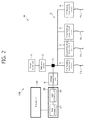
- FIG. 2 is a block diagram of the flooding detection apparatus including the flooding detection circuit 100 according to the embodiment of the present invention.
- the flooding detection apparatus 1000 includes the flooding detection circuit 100, a processing unit 200, and a display unit 300.
- the flooding detection circuit 100 has been described above and a description thereof is omitted.
- the processing unit 200 may include a data storage unit 210 and a data processing unit 220.
- the data storage unit 210 may store the divided voltage values of the voltage measurement node 50 according to the composite resistance values by the combinations of the first to N th flooding measurement resistors 31 to 34.
- the divided voltage values may be previously calculated on the basis of the composite resistance values, the resistance value of the reference resistor 20, and the supply voltage value of the power source unit 10 and then stored in the data storage unit 210.
- the data storage unit 210 may store pieces of position information about the first to N th flooding measurement resistors 31 to 34 corresponding to the respective divided voltage values in association with the respective divided voltage values. For example, a divided voltage value when the flooding contact terminal 31a of the first flooding measurement resistor 31 submerges may be recorded in association with the first flooding measurement resistor 31, a divided voltage value when the flooding contact terminal 32a of the second flooding measurement resistor 32 submerges may be recorded in association with the second flooding measurement resistor 32, and a divided voltage value when the flooding contact terminals 31a and 32a of the first and the second flooding measurement resistors 31 and 32 submerge may be recorded in association with the first flooding measurement resistor 31 and the second flooding measurement resistor 32. In case of other combinations of the first to N th flooding measurement resistors 31 to 34, a divided voltage value may be recorded likewise.
- the data processing unit 220 receives the divided voltage values measured by the voltage measurement unit 40 and compares the divided voltage values with the respective divided voltage values stored in the data storage unit 210.
- the data processing unit 220 may extract a divided voltage value equal to the divided voltage measured by the voltage measurement unit 40 or falling within a specific tolerance, from among the divided voltage values, and check information about the first to N th flooding measurement resistors 31 to 34 associated with the relevant divided voltage value.
- the composite resistance values by the combinations of the first to N th flooding measurement resistors 31 to 34 instead of the divided voltage values may be stored in the data storage unit 210. Furthermore, the pieces of position information about the first to N th flooding measurement resistors 31 to 34, corresponding to the respective composite resistance values, may be stored in association with the respective composite resistance values.
- the data processing unit 220 may receive the divided voltage values measured by the voltage measurement unit 40 and calculate the composite resistance values of the flooding unit 30 on the basis of the supply voltage value of the power source unit 10 and the resistance value of the reference resistor 20.
- the supply voltage value of the power source unit 10 may be previously stored, or the voltage value of the output terminal of the power source unit 10 may be detected in real time and used. It is preferred that previously stored data be used as the resistance value of the reference resistor 20 in order to improve the data processing speed and to simplify the apparatus.
- the data processing unit 220 may compare the calculated composite resistance values with the respective composite resistance values stored in the data storage unit 210, extract a composite resistance value equal to the stored composite resistance value or falling within a specific tolerance, from among the calculated composite resistance values, and check information about the first to N th flooding measurement resistors 31 to 34 associated with the relevant composite resistance value.
- This construction may be used to detect the voltage value of the output terminal of the power source unit 10 in real time and to use the detected voltage value in an operation. Accordingly, the construction may be applied to a variety of equipments using different voltages when the power source of equipment including the circuit is used as the power source unit 10.
- the processing unit 200 constructed as above can check whether flooding has occurred and check flooding positions at which the first to N th flooding measurement resistors 31 to 34 are placed on the basis of information about the first to N th flooding measurement resistors 31 to 34.
- the display unit 300 may be connected to the processing unit 200 and configured to visually inform a user of whether flooding has occurred and of a flooding position.
- a display device may be used as the display unit 300. Positions where the first to N th flooding measurement resistors 31 to 34 are placed may be displayed on a screen of the display device and, at the same time, a position where a submerged flooding measurement resistor is placed may be displayed on a screen of the display device.
- a plurality of flickering lamps may be used as the display unit 300. Only lamps displaying positions where submerged flooding measurement resistors are placed, from among the plurality of flickering lamps, may be flickered.
- the display unit 300 may display a flooding position and simultaneously generate an alarm to a user when flooding is detected.
- FIG. 3 is a diagram illustrating an example in which the flooding detection apparatus according to the embodiment of the present invention is applied to a vehicle.
- the first to N th flooding measurement resistors 31 to 34 may be installed in the respective elements of a vehicle 1.
- the first to N th flooding measurement resistors 31 to 34 are connected in parallel.
- the flooding contact terminals 31a to 34a may be included in the respective ends of the first to N th flooding measurement resistors 31 to 34.
- the flooding unit 30, including the first to N th flooding measurement resistors 31 to 34 and the flooding contact terminals 31a to 34a, is connected to the reference resistor 20.
- the voltage measurement node 50 is formed at the position where the flooding unit 30 and the reference resistor 20 are connected together.
- the voltage measurement unit 40 is connected to the voltage measurement node 50.
- An Analog to Digital Converter (ADC) may be used as the voltage measurement unit 40.
- the reference resistor 20 is connected to the power source unit 10.
- the power source unit 10 may be a vehicle battery embedded in the vehicle 1 or may be an electric charging source separately provided.
- the processing unit 200 may be connected to the voltage measurement unit 40 and configured to check whether the elements of the vehicle 1 in which the first to N th flooding measurement resistors 31 to 34 are installed have submerged.
- the construction of the processing unit 200 has been described above, and a description thereof is omitted.
- the processing unit 200 may be included in an Electronic Control Unit (ECU) 400 embedded in the vehicle 1.
- ECU Electronic Control Unit
- Information about the elements of the vehicle 1 whose flooding has been checked by the processing unit 200 is stored in the ECU 400.
- a diagnosis device (not shown) for checking the vehicle is connected to the ECU 400, relevant flooding information is displayed in the diagnosis device so that the subject of repair according to the flooding can be checked.
- the flooding detection apparatus according to the embodiment of the present invention may also be applied to a variety of large-sized machines and electronic equipments in addition to the vehicle.
- FIG. 4 is a diagram illustrating an example in which the flooding detection apparatus according to the embodiment of the present invention is applied to a factory.
- the flooding measurement resistors 31 to 35 may be installed in the respective sections A to E of the factory 2.
- the flooding measurement resistors 31 to 35 are connected in parallel.
- the flooding contact terminals 31a to 35a may be provided at the respective ends of the flooding measurement resistors 31 to 35.
- the flooding unit 30, including the flooding measurement resistors 31 to 35 and the flooding contact terminals 31a to 35a, is connected to the reference resistor 20.
- the voltage measurement node 50 is formed at a portion at which the flooding unit 30 and the reference resistor 20 are connected together.
- the voltage measurement unit 40 is connected to the voltage measurement node 50.
- An Analog to Digital Converter (ADC) may be used as the voltage measurement unit 40.
- the reference resistor 20 is connected to the power source unit 10.
- the processing unit 200 may be connected to the voltage measurement unit 40 and configured to check whether flooding has occurred in each of the sections A to E of the factory 2 in which the flooding measurement resistors 31 to 34 are installed.
- the construction of the processing unit 200 has been described, and a description thereof is omitted.
- the display unit 300 connected to the processing unit 200 may be provided in a control room F in which the entire factory 2 is managed controlled and configured to display flooding occurring in each of the sections A to E of the factory 2 in which the flooding measurement resistors 31 to 34 are installed.
- the display device or the plurality of flickering lamps may be used as the display unit 300.
- the present invention may also be applied buildings, large-sized equipments, etc. using a similar construction.
- the flooding detection circuit and the flooding detection apparatus according to the present invention can check whether flooding has occurred and a flooding position.
- a circuit can be configured at a low price, the circuit can be easily installed, and the number of places whose flooding is measured can be easily increased.
Abstract
Description
- This application claims the benefit of priority of Korean Patent Application No.
2011-0095082 filed on September 21, 2011 10-2012-0015596 filed on February 16, 2012 - The present invention relates to a flooding detection circuit and a flooding detection apparatus using same and, more particularly, to a flooding detection circuit capable of checking a flooding position and a flooding detection apparatus using same.
- Electrical and electronic equipments, machines, etc. may have their functions deteriorated or lost if they submerge. Accordingly, submerged electrical and electronic equipments, submerged machines, etc. require instant repair or replacement.
- Particularly, if only some of the parts of equipment including a plurality of parts submerge, it is important to check the degree of flooding and the flooding position of the equipment in order to check whether to replace or repair the equipment.
- Furthermore, in large-sized equipments, factories, etc. in addition to electrical and electronic equipments or machines, it is important to check the degree of flooding and the flooding position in order to maintain the equipment or facilities.
- Korean Patent No.
536524 - The present invention provides a flooding detection circuit and a flooding detection apparatus using a plurality of resistors which is electrified by flooding.
- In order to achieve the above, a flooding detection circuit according to an aspect of the present invention includes a power source unit; a reference resistor connected between the power source unit and a voltage measurement node; a flooding unit configured to include a plurality of flooding measurement resistors connected in parallel to the voltage measurement node, wherein flooding contact terminals are formed at respective ends of the flooding measurement resistors; and a voltage measurement unit connected to the voltage measurement node and configured to measure voltage divided by the reference resistor and the flooding unit when the flooding contact terminals submerge.
- Composite resistance values of one or more of the plurality of flooding measurement resistors may be different from each other.
- The plurality of flooding measurement resistors may have different resistance values.
- The plurality of flooding measurement resistors may have resistance value of different prime numbers.
- The flooding contact terminals may be electrical wires extended from the respective flooding measurement resistors.
- The voltage measurement unit may be an Analog to Digital Converter (ADC).
- A flooding detection apparatus according to another aspect of the present invention includes a power source unit; a reference resistor configured to have one terminal connected to the power source unit and have the other terminal connected to a voltage measurement node; a flooding unit configured to include a plurality of flooding measurement resistors connected in parallel to the voltage measurement node and placed in respective flooding measurement positions; a voltage measurement unit connected to the voltage measurement node and configured to measure divided voltage values divided by the reference resistor and the flooding unit; and a processing unit connected to the voltage measurement unit and configured to determine whether flooding has occurred and flooding measurement positions based on the divided voltage values.
- Flooding contact terminals are included at respective ends of the plurality of flooding measurement resistors, and the plurality of flooding measurement resistors are electrified when the flooding contact terminals submerge.
- Composite resistance values by combinations of the plurality of flooding measurement resistors may be different from each other.
- The processing unit may include a data storage unit for storing the divided voltage values according to the respective composite resistance values.
- The data storage unit may further store the flooding measurement positions which correspond to the respective divided voltage values and where the respective flooding measurement resistors are placed.
- The processing unit determines whether flooding has occurred and the flooding measurement positions by comparing the divided voltage values, measured by the voltage measurement unit, with the respective divided voltage values stored in the data storage unit.
- The processing unit may include a data storage unit for storing the composite resistance values.
- The data storage unit may further store the flooding measurement positions which correspond to the respective composite resistance values and where the respective flooding measurement resistors are placed, in association with the composite resistance values.
- The processing unit further may include a reverse composite resistance value calculation unit for calculating reverse composite resistance values of the flooding unit based on the divided voltage values, a supply voltage of the power source unit, and a resistance value of the reference resistor.
- The processing unit determines whether flooding has occurred and the flooding measurement positions by comparing the reverse composite resistance values of the reverse composite resistance value calculation unit with the respective composite resistance values stored in the data storage unit.
- The flooding detection apparatus may further include a display unit for displaying whether flooding has occurred and the flooding measurement positions by the processing unit.
-
-
FIG. 1 is a block diagram of a flooding detection circuit according to an embodiment of the present invention. -
FIG. 2 is a block diagram of a flooding detection apparatus according to an embodiment of the present invention. -
FIG. 3 is a diagram illustrating an example in which the flooding detection apparatus according to the embodiment of the present invention is applied to a vehicle. -
FIG. 4 is a diagram illustrating an example in which the flooding detection apparatus according to the embodiment of the present invention is applied to a factory. - Hereinafter, some embodiments of the present invention will be described in detail with reference to the accompanying drawings. However, the present invention is not limited to the disclosed embodiments, but may be implemented in various ways. The present embodiments are provided to complete the disclosure of the present invention and to allow those having ordinary skill in the art to understand the scope of the present invention. The shapes, etc., of elements in the drawings may be enlarged in order to highlight a clearer description. The same reference numbers are used throughout the drawings to refer to the same parts.
-
FIG. 1 is a block diagram of a flooding detection circuit according to an embodiment of the present invention. - As shown in
FIG. 1 , theflooding detection circuit 100 according to the embodiment of the present invention includes apower source unit 10, areference resistor 20, aflooding unit 30, and avoltage measurement unit 40. - The
power source unit 10 is an electrical source for supplying voltage to theflooding detection circuit 100. - The driving source of an apparatus or equipment on which the
flooding detection circuit 100 is mounted may be used as thepower source unit 10. Alternatively, thepower source unit 10 may be a power source additionally included in theflooding detection circuit 100. - The
power source unit 10 may be connected to one terminal of thereference resistor 20. Furthermore, the other terminal of thereference resistor 20 may be connected to theflooding unit 30. - The
flooding unit 30 includes a plurality of first to Nthflooding measurement resistors 31 to 34 connected in parallel. - Each of the first to Nth
flooding measurement resistors 31 to 34 may be formed of a resistor having a different impedance. - Furthermore, composite resistance values according to all the combinations of one or more of the first to Nth
flooding measurement resistors 31 to 34 may be different. - For example, in order for the composite resistance values to be different, the impedance of each of the first to Nth
flooding measurement resistors 31 to 34 may have a different prime number. For example, resistance values of N different prime numbers may be selected in such a manner that the firstflooding measurement resistor 31 has 3 KΩ, the secondflooding measurement resistor 32 has 5 KΩ, the thirdflooding measurement resistor 33 has 7 KΩ, a fourth flooding measurement resistor (not shown) has 11 KΩ, etc. - Meanwhile,
flooding contact terminals 31a to 34a may be provided at the respective ends of the first to Nthflooding measurement resistors 31 to 34. - The
flooding contact terminals 31 a to 34a are parts coming in contact with water when flooding occurs. When theflooding contact terminals 31 a to 34a submerge, the first to Nthflooding measurement resistors 31 to 34, thereference resistor 20, and thepower source unit 10 form a closed circuit. - The
flooding contact terminals 31 a to 34a may be made of conductive material and may be electrical wires extended from the first to Nthflooding measurement resistors 31 to 34. - Accordingly, of some of the
flooding contact terminals 31a to 34a submerge, flooding measurement resistors connected to the submerged flooding contact terminals are electrified, but flooding measurement resistors connected to flooding contact terminals not submerged are not electrified. - Meanwhile, the
voltage measurement unit 40 is connected to a point 50 (hereinafter referred to as a voltage measurement node) at which thereference resistor 20 and theflooding unit 30 are connected together. Thus, voltage at thevoltage measurement node 50 can be measured. - If flooding does not occur, voltage supplied by the
power source unit 10 is supplied to only thereference resistor 20 because current does not flow through theflooding unit 30. - If some or all of the
flooding contact terminals 31a to 34a submerge, however, current passing through thereference resistor 20 flows into flooding measurement resistors connected to the submerged flooding contact terminals, and voltage supplied by thepower source unit 10 is divided into thereference resistor 20 and the relevant flooding measurement resistors. - Accordingly, whether flooding has occurred can be checked on the basis of voltage at the
voltage measurement node 50 which is measured by thevoltage measurement unit 40. - Furthermore, the impedances of the first to Nth
flooding measurement resistors 31 to 34 are selected so that the composite resistance values according to the combinations of the first to Nthflooding measurement resistors 31 to 34 are different as described above. Thus, thevoltage measurement node 50 has a different voltage value depending on a flooding position. Accordingly, even a submerged flooding position can be determined by checking only the voltage of thevoltage measurement node 50 which is measured by thevoltage measurement unit 40. - For example, assuming that the
power source unit 10 supplies DC voltage of 5 V, thereference resistor 20 has 5 KΩ, the firstflooding measurement resistor 31 has 3 KΩ, the secondflooding measurement resistor 32 has 5 KΩ, and the thirdflooding measurement resistor 33 has 7KΩ, - 1) if only the
flooding contact terminal 31a connected to the firstflooding measurement resistor 31 submerges, voltage measured by thevoltage measurement unit 40 is 5*{3/(3+5)}=1.875 V, - 2) if only the
flooding contact terminal 32a connected to the secondflooding measurement resistor 32 submerges, voltage measured by thevoltage measurement unit 40 is 5*{5/(5+5)}=2.5 V, - 3) if only the
flooding contact terminal 33a connected to the thirdflooding measurement resistor 33 submerges, voltage measured by thevoltage measurement unit 40 is 5* {7/(7+5)}=2.917 V, - 4) if only the
flooding contact terminal 31 a connected to the firstflooding measurement resistor 31 and theflooding contact terminal 32a connected to the secondflooding measurement resistor 32 submerge, voltage measured by thevoltage measurement unit 40 is 5*{1.875/(1.875+5)}≒1.364 V, - 5) if only the
flooding contact terminal 31 a connected to the firstflooding measurement resistor 31 and theflooding contact terminal 33a connected to the thirdflooding measurement resistor 33 submerge, voltage measured by thevoltage measurement unit 40 is 5*{2.1/(2.1+5)}≒1.479 V, - 6) if only the
flooding contact terminal 32a connected to the secondflooding measurement resistor 32 and theflooding contact terminal 33a connected to the thirdflooding measurement resistor 33 submerge, voltage measured by thevoltage measurement unit 40 is 5*{2.917/(2.917+5)}≒1.842 V, and - 7) if only the
flooding contact terminal 31 a connected to the firstflooding measurement resistor 31, theflooding contact terminal 32a connected to the secondflooding measurement resistor 32, and theflooding contact terminal 33a connected to the thirdflooding measurement resistor 33 submerge, voltage measured by thevoltage measurement unit 40 is 5* {1.479/(1.479+5)}≒1.141 V. - As in the above example, voltage measured by the
voltage measurement unit 40 is different depending on a flooding position. Accordingly, a flooding position can be checked on the basis of the measured voltage. In other words, if voltage measured by thevoltage measurement unit 40 is 2.5 V, it can be seen that only a position where the secondflooding measurement resistor 32 is placed has submerge. If voltage measured by thevoltage measurement unit 40 is 1.141 V, it can be seen that only positions where the firstflooding measurement resistor 31, the secondflooding measurement resistor 32, and the thirdflooding measurement resistor 33 have submerged. - An Analog to Digital Converter (ADC) for converting the voltage value (i.e., an analog value) of the
voltage measurement node 50 into a digital value may be used as thevoltage measurement unit 40. - The
flooding detection circuit 100 according to the embodiment of the present invention includes the first to Nthflooding measurement resistors 31 to 34 equipped with the respectiveflooding contact terminals 31 a to 34a instead of the conventional differential pressure sensors or floating sensors in order to check flooding. Accordingly, whether flooding has occurred and a flooding position can be checked, and a circuit can be configured at a low price. - Furthermore, if additional flooding measurement resistors are connected in parallel to the first to Nth
flooding measurement resistors 31 to 34, the number of places where the occurrence of flooding is measured can be increased. Here, the circuits can be easily extended and installed. - A flooding detection apparatus according to an embodiment of the present invention is described below.
-
FIG. 2 is a block diagram of the flooding detection apparatus including theflooding detection circuit 100 according to the embodiment of the present invention. - As shown in
FIG. 2 , theflooding detection apparatus 1000 according to the embodiment of the present invention includes theflooding detection circuit 100, aprocessing unit 200, and adisplay unit 300. - The
flooding detection circuit 100 has been described above and a description thereof is omitted. - The
processing unit 200 may include adata storage unit 210 and adata processing unit 220. - The
data storage unit 210 may store the divided voltage values of thevoltage measurement node 50 according to the composite resistance values by the combinations of the first to Nthflooding measurement resistors 31 to 34. - The divided voltage values may be previously calculated on the basis of the composite resistance values, the resistance value of the
reference resistor 20, and the supply voltage value of thepower source unit 10 and then stored in thedata storage unit 210. - The
data storage unit 210 may store pieces of position information about the first to Nthflooding measurement resistors 31 to 34 corresponding to the respective divided voltage values in association with the respective divided voltage values. For example, a divided voltage value when theflooding contact terminal 31a of the firstflooding measurement resistor 31 submerges may be recorded in association with the firstflooding measurement resistor 31, a divided voltage value when theflooding contact terminal 32a of the secondflooding measurement resistor 32 submerges may be recorded in association with the secondflooding measurement resistor 32, and a divided voltage value when theflooding contact terminals flooding measurement resistors flooding measurement resistor 31 and the secondflooding measurement resistor 32. In case of other combinations of the first to Nthflooding measurement resistors 31 to 34, a divided voltage value may be recorded likewise. - The
data processing unit 220 receives the divided voltage values measured by thevoltage measurement unit 40 and compares the divided voltage values with the respective divided voltage values stored in thedata storage unit 210. - The
data processing unit 220 may extract a divided voltage value equal to the divided voltage measured by thevoltage measurement unit 40 or falling within a specific tolerance, from among the divided voltage values, and check information about the first to Nthflooding measurement resistors 31 to 34 associated with the relevant divided voltage value. - In an alternative embodiment, the composite resistance values by the combinations of the first to Nth
flooding measurement resistors 31 to 34 instead of the divided voltage values may be stored in thedata storage unit 210. Furthermore, the pieces of position information about the first to Nthflooding measurement resistors 31 to 34, corresponding to the respective composite resistance values, may be stored in association with the respective composite resistance values. - The
data processing unit 220 may receive the divided voltage values measured by thevoltage measurement unit 40 and calculate the composite resistance values of theflooding unit 30 on the basis of the supply voltage value of thepower source unit 10 and the resistance value of thereference resistor 20. - In this case, the supply voltage value of the
power source unit 10 may be previously stored, or the voltage value of the output terminal of thepower source unit 10 may be detected in real time and used. It is preferred that previously stored data be used as the resistance value of thereference resistor 20 in order to improve the data processing speed and to simplify the apparatus. - The
data processing unit 220 may compare the calculated composite resistance values with the respective composite resistance values stored in thedata storage unit 210, extract a composite resistance value equal to the stored composite resistance value or falling within a specific tolerance, from among the calculated composite resistance values, and check information about the first to Nthflooding measurement resistors 31 to 34 associated with the relevant composite resistance value. - This construction may be used to detect the voltage value of the output terminal of the
power source unit 10 in real time and to use the detected voltage value in an operation. Accordingly, the construction may be applied to a variety of equipments using different voltages when the power source of equipment including the circuit is used as thepower source unit 10. - The
processing unit 200 constructed as above can check whether flooding has occurred and check flooding positions at which the first to Nthflooding measurement resistors 31 to 34 are placed on the basis of information about the first to Nthflooding measurement resistors 31 to 34. - The
display unit 300 may be connected to theprocessing unit 200 and configured to visually inform a user of whether flooding has occurred and of a flooding position. - A display device may be used as the
display unit 300. Positions where the first to Nthflooding measurement resistors 31 to 34 are placed may be displayed on a screen of the display device and, at the same time, a position where a submerged flooding measurement resistor is placed may be displayed on a screen of the display device. - In an alternative embodiment, a plurality of flickering lamps may be used as the
display unit 300. Only lamps displaying positions where submerged flooding measurement resistors are placed, from among the plurality of flickering lamps, may be flickered. - The
display unit 300 may display a flooding position and simultaneously generate an alarm to a user when flooding is detected. - Examples in which the flooding detection apparatus according to the embodiment of the present invention is applied are described below.
FIG. 3 is a diagram illustrating an example in which the flooding detection apparatus according to the embodiment of the present invention is applied to a vehicle. - As shown in
FIG. 3 , the first to Nthflooding measurement resistors 31 to 34 may be installed in the respective elements of avehicle 1. The first to Nthflooding measurement resistors 31 to 34 are connected in parallel. Furthermore, theflooding contact terminals 31a to 34a may be included in the respective ends of the first to Nthflooding measurement resistors 31 to 34. - The
flooding unit 30, including the first to Nthflooding measurement resistors 31 to 34 and theflooding contact terminals 31a to 34a, is connected to thereference resistor 20. Thevoltage measurement node 50 is formed at the position where theflooding unit 30 and thereference resistor 20 are connected together. - The
voltage measurement unit 40 is connected to thevoltage measurement node 50. An Analog to Digital Converter (ADC) may be used as thevoltage measurement unit 40. - The
reference resistor 20 is connected to thepower source unit 10. Thepower source unit 10 may be a vehicle battery embedded in thevehicle 1 or may be an electric charging source separately provided. - The
processing unit 200 may be connected to thevoltage measurement unit 40 and configured to check whether the elements of thevehicle 1 in which the first to Nthflooding measurement resistors 31 to 34 are installed have submerged. The construction of theprocessing unit 200 has been described above, and a description thereof is omitted. - The
processing unit 200 may be included in an Electronic Control Unit (ECU) 400 embedded in thevehicle 1. - Information about the elements of the
vehicle 1 whose flooding has been checked by theprocessing unit 200 is stored in theECU 400. When a diagnosis device (not shown) for checking the vehicle is connected to theECU 400, relevant flooding information is displayed in the diagnosis device so that the subject of repair according to the flooding can be checked. - Whether a vehicle has submerged and a submerged part of the vehicle can be easily checked through the above construction.
- The flooding detection apparatus according to the embodiment of the present invention may also be applied to a variety of large-sized machines and electronic equipments in addition to the vehicle.
-
FIG. 4 is a diagram illustrating an example in which the flooding detection apparatus according to the embodiment of the present invention is applied to a factory. - As shown in
FIG. 4 , theflooding measurement resistors 31 to 35 may be installed in the respective sections A to E of thefactory 2. Theflooding measurement resistors 31 to 35 are connected in parallel. Furthermore, theflooding contact terminals 31a to 35a may be provided at the respective ends of theflooding measurement resistors 31 to 35. - The
flooding unit 30, including theflooding measurement resistors 31 to 35 and theflooding contact terminals 31a to 35a, is connected to thereference resistor 20. Thevoltage measurement node 50 is formed at a portion at which theflooding unit 30 and thereference resistor 20 are connected together. - The
voltage measurement unit 40 is connected to thevoltage measurement node 50. An Analog to Digital Converter (ADC) may be used as thevoltage measurement unit 40. - The
reference resistor 20 is connected to thepower source unit 10. - The
processing unit 200 may be connected to thevoltage measurement unit 40 and configured to check whether flooding has occurred in each of the sections A to E of thefactory 2 in which theflooding measurement resistors 31 to 34 are installed. The construction of theprocessing unit 200 has been described, and a description thereof is omitted. - The
display unit 300 connected to theprocessing unit 200 may be provided in a control room F in which theentire factory 2 is managed controlled and configured to display flooding occurring in each of the sections A to E of thefactory 2 in which theflooding measurement resistors 31 to 34 are installed. As described above, the display device or the plurality of flickering lamps may be used as thedisplay unit 300. - Whether flooding has occurred in a factory and a flooding section can be easily checked through the construction. Furthermore, the present invention may also be applied buildings, large-sized equipments, etc. using a similar construction.
- The flooding detection circuit and the flooding detection apparatus according to the present invention can check whether flooding has occurred and a flooding position.
- Furthermore, a circuit can be configured at a low price, the circuit can be easily installed, and the number of places whose flooding is measured can be easily increased.
- The embodiments of the present invention described above and shown in the drawings should not be construed as limiting the technical spirit of the present invention. The scope of the present invention is restricted by only the claims, and a person having ordinary skill in the art to which the present invention pertains may improve and modify the technical spirit of the present invention in various forms. Accordingly, the modifications and modifications will fall within the scope of the present invention as long as they are evident to those skilled in the art.
Claims (17)
- A flooding detection circuit, comprising
a power source unit;
a reference resistor connected between the power source unit and a voltage measurement node;
a flooding unit configured to include a plurality of flooding measurement resistors connected in parallel to the voltage measurement node, wherein flooding contact terminals are formed at respective ends of the flooding measurement resistors; and
a voltage measurement unit connected to the voltage measurement node and configured to measure voltage divided by the reference resistor and the flooding unit when the flooding contact terminals submerge. - The flooding detection circuit as claimed in claim 1, wherein composite resistance values of one or more of the plurality of flooding measurement resistors are different from each other.
- The flooding detection circuit as claimed in claim 2, wherein the plurality of flooding measurement resistors has different resistance values.
- The flooding detection circuit as claimed in claim 2, wherein the plurality of flooding measurement resistors has resistance value of different prime numbers.
- The flooding detection circuit as claimed in claim 1, wherein the flooding contact terminals are electrical wires extended from the respective flooding measurement resistors.
- The flooding detection circuit as claimed in claim 1, wherein the voltage measurement unit is an Analog to Digital Converter (ADC).
- A flooding detection apparatus, comprising:a power source unit;a reference resistor configured to have one terminal connected to the power source unit and have the other terminal connected to a voltage measurement node;a flooding unit configured to include a plurality of flooding measurement resistors connected in parallel to the voltage measurement node and placed in respective flooding measurement positions;a voltage measurement unit connected to the voltage measurement node and configured to measure divided voltage values divided by the reference resistor and the flooding unit; anda processing unit connected to the voltage measurement unit and configured to determine whether flooding has occurred and flooding measurement positions based on the divided voltage values.
- The flooding detection apparatus as claimed in claim 7, wherein:flooding contact terminals are included at respective ends of the plurality of flooding measurement resistors, andthe plurality of flooding measurement resistors is electrified when the flooding contact terminals submerge.
- The flooding detection apparatus as claimed in claim 7, wherein composite resistance values by combinations of the plurality of flooding measurement resistors are different from each other.
- The flooding detection apparatus as claimed in claim 9, wherein the processing unit comprises a data storage unit for storing the divided voltage values according to the respective composite resistance values.
- The flooding detection apparatus as claimed in claim 10, wherein the data storage unit further stores the flooding measurement positions which correspond to the respective divided voltage values and where the respective flooding measurement resistors are placed.
- The flooding detection apparatus as claimed in claim 10, wherein the processing unit determines whether flooding has occurred and the flooding measurement positions by comparing the divided voltage values, measured by the voltage measurement unit, with the respective divided voltage values stored in the data storage unit.
- The flooding detection apparatus as claimed in claim 9, wherein the processing unit comprises a data storage unit for storing the composite resistance values.
- The flooding detection apparatus as claimed in claim 13, wherein the data storage unit further stores the flooding measurement positions which correspond to the respective composite resistance values and where the respective flooding measurement resistors are placed, in association with the composite resistance values.
- The flooding detection apparatus as claimed in claim 13, wherein the processing unit further comprises a reverse composite resistance value calculation unit for calculating reverse composite resistance values of the flooding unit based on the divided voltage values, a supply voltage of the power source unit, and a resistance value of the reference resistor.
- The flooding detection apparatus as claimed in claim 15, wherein the processing unit determines whether flooding has occurred and the flooding measurement positions by comparing the reverse composite resistance values of the reverse composite resistance value calculation unit with the respective composite resistance values stored in the data storage unit.
- The flooding detection apparatus as claimed in claim 7, further comprising a display unit for displaying whether flooding has occurred and the flooding measurement positions by the processing unit.
Applications Claiming Priority (2)
| Application Number | Priority Date | Filing Date | Title |
|---|---|---|---|
| KR20110095082 | 2011-09-21 | ||
| PCT/KR2012/001175 WO2013042842A1 (en) | 2011-09-21 | 2012-02-16 | Flooding detection circuit and flooding detection apparatus using same |
Publications (2)
| Publication Number | Publication Date |
|---|---|
| EP2669874A1 true EP2669874A1 (en) | 2013-12-04 |
| EP2669874A4 EP2669874A4 (en) | 2015-01-14 |
Family
ID=48180843
Family Applications (1)
| Application Number | Title | Priority Date | Filing Date |
|---|---|---|---|
| EP12833372.1A Ceased EP2669874A4 (en) | 2011-09-21 | 2012-02-16 | Flooding detection circuit and flooding detection apparatus using same |
Country Status (6)
| Country | Link |
|---|---|
| US (1) | US8990030B2 (en) |
| EP (1) | EP2669874A4 (en) |
| JP (1) | JP5717262B2 (en) |
| KR (1) | KR101306506B1 (en) |
| CN (1) | CN103430223B (en) |
| WO (1) | WO2013042842A1 (en) |
Families Citing this family (14)
| Publication number | Priority date | Publication date | Assignee | Title |
|---|---|---|---|---|
| EP2755002B1 (en) * | 2013-01-15 | 2022-03-16 | Electrolux Home Products Corporation N.V. | A level measurement system for conductive liquids |
| SE541032C2 (en) | 2015-02-27 | 2019-03-12 | Ningbo Geely Automobile Res & Development Co Ltd | Methods and systems for detecting faults in vehicle control systems |
| EP3442420A4 (en) * | 2016-04-12 | 2019-11-27 | Gogo Band, Inc. | Urination prediction and monitoring |
| DK3264383T3 (en) * | 2016-06-29 | 2019-06-03 | Ontech Security Sl | DEVICE AND PROCEDURE FOR WATERSTAND DETECTION |
| CN106595977A (en) * | 2016-12-16 | 2017-04-26 | 国家电网公司 | Equipment insulation oil leakage monitoring alarm apparatus |
| CN108725315B (en) * | 2017-04-21 | 2023-08-01 | 宇通客车股份有限公司 | New energy automobile |
| DE102017211278A1 (en) * | 2017-07-03 | 2019-01-03 | Robert Bosch Gmbh | Method for operating a steering system and steering system |
| KR102324254B1 (en) * | 2017-08-31 | 2021-11-08 | 주식회사 엘지에너지솔루션 | Apparatus for detecting leak and battery pack including the same, vehicle including the same |
| DE102018201422A1 (en) * | 2018-01-30 | 2019-08-01 | Brose Fahrzeugteile Gmbh & Co. Kommanditgesellschaft, Bamberg | Electronic control unit |
| KR20190092740A (en) | 2018-01-31 | 2019-08-08 | 삼성전자주식회사 | Electronic device for determining whether to flooding of the electronic device using flooding detection circuit and method for the same |
| CN109377724A (en) * | 2018-10-30 | 2019-02-22 | 出门问问信息科技有限公司 | Immersion warning device and its control method |
| KR102005241B1 (en) * | 2019-06-17 | 2019-07-30 | 주식회사 대영파워펌프 | Inverter booster pump system |
| CN111289801B (en) * | 2020-02-11 | 2022-05-10 | 南京工程学院 | Two-dimensional resistor array reading circuit, method and system |
| FR3109443A1 (en) * | 2020-04-16 | 2021-10-22 | Psa Automobiles Sa | FLUID LEAK DETECTION SYSTEM |
Citations (4)
| Publication number | Priority date | Publication date | Assignee | Title |
|---|---|---|---|---|
| US3778797A (en) * | 1972-07-10 | 1973-12-11 | Pyott Boone Inc | Multi-station safety monitor having shunt switch |
| US4524349A (en) * | 1982-08-09 | 1985-06-18 | Nel-Tech Development, Inc. | Security system having detector sensing and identification |
| US4939511A (en) * | 1988-12-27 | 1990-07-03 | Grumman Aerospace Corporation | DC bus for discrete signals |
| WO2009115131A1 (en) * | 2008-03-20 | 2009-09-24 | Nokia Corporation | Detection of water ingress to an apparatus by resistance measurments between two electrodes |
Family Cites Families (16)
| Publication number | Priority date | Publication date | Assignee | Title |
|---|---|---|---|---|
| GB760668A (en) * | 1953-12-17 | 1956-11-07 | Philips Electrical Ind Ltd | Improvements in or relating to devices for measuring a physical quantity |
| JPS5249405Y2 (en) * | 1972-05-29 | 1977-11-10 | ||
| JPS63122237U (en) * | 1987-01-31 | 1988-08-09 | ||
| JPH0464022A (en) * | 1990-07-03 | 1992-02-28 | Matsushita Electric Ind Co Ltd | Detecting apparatus for remaining amount of liquid |
| JPH06307968A (en) * | 1993-04-27 | 1994-11-04 | Sumitomo Electric Ind Ltd | Water permeation detector for electronic circuit unit |
| JP2660990B2 (en) * | 1995-09-04 | 1997-10-08 | 平田機工株式会社 | Electric welding equipment |
| JP3618514B2 (en) * | 1997-06-06 | 2005-02-09 | 理想科学工業株式会社 | Bag-in carton and liquid remaining amount detection device using the same |
| JP2002188977A (en) * | 2000-12-21 | 2002-07-05 | Furukawa Electric Co Ltd:The | Detection device of liquid penetration or liquid level |
| KR100536524B1 (en) | 2003-11-22 | 2005-12-14 | 이승규 | A flooding sensor and the system for warning of flooding thereof |
| KR100555590B1 (en) * | 2004-06-04 | 2006-03-03 | 주식회사 로템 | a tanks flooding prevention systems |
| JP2006308422A (en) * | 2005-04-28 | 2006-11-09 | Akebono Brake Ind Co Ltd | Onboard semiconductor sensor |
| JP2007218740A (en) * | 2006-02-16 | 2007-08-30 | Taiheiyo Cement Corp | Liquid level sensor device, concrete product, and submergence state detection system |
| KR100899632B1 (en) * | 2007-08-07 | 2009-05-27 | 엘에스산전 주식회사 | Electricity meter with a function for detecting failure of current transformer |
| JP2009210262A (en) * | 2008-02-29 | 2009-09-17 | National Research Institute For Earth Science & Disaster Provention | Coupling sensor for measuring depth of immersion and measuring method using the same |
| CN201532376U (en) * | 2009-11-18 | 2010-07-21 | 张友贵 | Soil moisture indicator |
| KR101202841B1 (en) * | 2010-06-15 | 2012-11-20 | 주식회사 디앤샤인 | System and Method for Monitoring Flooding of Road |
-
2012
- 2012-02-16 JP JP2013556539A patent/JP5717262B2/en active Active
- 2012-02-16 KR KR1020120015596A patent/KR101306506B1/en active IP Right Grant
- 2012-02-16 CN CN201280011906.2A patent/CN103430223B/en active Active
- 2012-02-16 WO PCT/KR2012/001175 patent/WO2013042842A1/en active Application Filing
- 2012-02-16 EP EP12833372.1A patent/EP2669874A4/en not_active Ceased
- 2012-04-17 US US13/448,841 patent/US8990030B2/en active Active
Patent Citations (4)
| Publication number | Priority date | Publication date | Assignee | Title |
|---|---|---|---|---|
| US3778797A (en) * | 1972-07-10 | 1973-12-11 | Pyott Boone Inc | Multi-station safety monitor having shunt switch |
| US4524349A (en) * | 1982-08-09 | 1985-06-18 | Nel-Tech Development, Inc. | Security system having detector sensing and identification |
| US4939511A (en) * | 1988-12-27 | 1990-07-03 | Grumman Aerospace Corporation | DC bus for discrete signals |
| WO2009115131A1 (en) * | 2008-03-20 | 2009-09-24 | Nokia Corporation | Detection of water ingress to an apparatus by resistance measurments between two electrodes |
Non-Patent Citations (1)
| Title |
|---|
| See also references of WO2013042842A1 * |
Also Published As
| Publication number | Publication date |
|---|---|
| EP2669874A4 (en) | 2015-01-14 |
| US20130073237A1 (en) | 2013-03-21 |
| US8990030B2 (en) | 2015-03-24 |
| CN103430223A (en) | 2013-12-04 |
| CN103430223B (en) | 2016-07-06 |
| JP5717262B2 (en) | 2015-05-13 |
| KR101306506B1 (en) | 2013-09-09 |
| WO2013042842A1 (en) | 2013-03-28 |
| KR20130031763A (en) | 2013-03-29 |
| JP2014511491A (en) | 2014-05-15 |
Similar Documents
| Publication | Publication Date | Title |
|---|---|---|
| US8990030B2 (en) | Submersion detection circuit and submersion detection apparatus using the same | |
| JP5861954B2 (en) | Battery insulation resistance measuring apparatus and method | |
| JP5560474B2 (en) | Dielectric breakdown detection circuit | |
| JP6071080B2 (en) | Insulation resistance measuring device with self-fault diagnostic function and self-fault diagnostic method using the same | |
| CN107110900A (en) | Insulation resistance measuring device and method | |
| US8427167B2 (en) | Architecture and method to determine leakage impedance and leakage voltage node | |
| JP6206317B2 (en) | Power storage system | |
| CN104730313B (en) | Method and apparatus for detecting leakage current between the power supplies | |
| KR101322519B1 (en) | Detecting apparatus of short circuit for electric car and detecting method of short circuit using the same | |
| JP6691779B2 (en) | System for measuring contact force in utility meters | |
| JP2015206604A (en) | Electrochemical measurement device | |
| JP2013068452A (en) | Current sensor failure diagnosis equipment | |
| TW201633850A (en) | Fault detection apparatus and fault detection method | |
| CN110945369B (en) | System and method for testing charging device | |
| JP2016208705A (en) | Solar battery fault detection device | |
| JP5858219B2 (en) | Method and apparatus for measuring ac impedance of storage battery and life diagnosis apparatus | |
| JP6883382B2 (en) | Leakage detector | |
| JP4788868B2 (en) | Earthester and ground resistance measurement method | |
| JP6491852B2 (en) | Circuit element measuring device | |
| JP2010190574A (en) | Liquid leak detector | |
| JP2011185612A (en) | Connector connection discrimination device | |
| JP2013217809A (en) | Handy type wiring checker and method for checking wiring conduction | |
| JP2016101012A (en) | Ground fault detector and ground fault detection method | |
| US20190154744A1 (en) | Electrical Circuit Testing System | |
| JP6038529B2 (en) | measuring device |
Legal Events
| Date | Code | Title | Description |
|---|---|---|---|
| PUAI | Public reference made under article 153(3) epc to a published international application that has entered the european phase |
Free format text: ORIGINAL CODE: 0009012 |
|
| 17P | Request for examination filed |
Effective date: 20130828 |
|
| AK | Designated contracting states |
Kind code of ref document: A1 Designated state(s): AL AT BE BG CH CY CZ DE DK EE ES FI FR GB GR HR HU IE IS IT LI LT LU LV MC MK MT NL NO PL PT RO RS SE SI SK SM TR |
|
| DAX | Request for extension of the european patent (deleted) | ||
| A4 | Supplementary search report drawn up and despatched |
Effective date: 20141211 |
|
| RIC1 | Information provided on ipc code assigned before grant |
Ipc: G08B 25/01 20060101ALI20141205BHEP Ipc: G01M 3/16 20060101ALI20141205BHEP Ipc: G08B 21/20 20060101AFI20141205BHEP |
|
| 17Q | First examination report despatched |
Effective date: 20160601 |
|
| REG | Reference to a national code |
Ref country code: DE Ref legal event code: R003 |
|
| RAP1 | Party data changed (applicant data changed or rights of an application transferred) |
Owner name: LG CHEM, LTD. |
|
| STAA | Information on the status of an ep patent application or granted ep patent |
Free format text: STATUS: THE APPLICATION HAS BEEN REFUSED |
|
| 18R | Application refused |
Effective date: 20180523 |