EP2669192A1 - Propeller blade - Google Patents
Propeller blade Download PDFInfo
- Publication number
- EP2669192A1 EP2669192A1 EP12305590.7A EP12305590A EP2669192A1 EP 2669192 A1 EP2669192 A1 EP 2669192A1 EP 12305590 A EP12305590 A EP 12305590A EP 2669192 A1 EP2669192 A1 EP 2669192A1
- Authority
- EP
- European Patent Office
- Prior art keywords
- fibrous material
- propeller blade
- groove
- core
- structural layer
- Prior art date
- Legal status (The legal status is an assumption and is not a legal conclusion. Google has not performed a legal analysis and makes no representation as to the accuracy of the status listed.)
- Granted
Links
- 239000002657 fibrous material Substances 0.000 claims abstract description 32
- 239000006260 foam Substances 0.000 claims abstract description 26
- 239000011347 resin Substances 0.000 claims description 13
- 229920005989 resin Polymers 0.000 claims description 13
- 229920000049 Carbon (fiber) Polymers 0.000 claims description 7
- 239000004917 carbon fiber Substances 0.000 claims description 7
- 238000000034 method Methods 0.000 claims description 5
- 239000011152 fibreglass Substances 0.000 claims description 4
- 239000000463 material Substances 0.000 claims description 4
- OKTJSMMVPCPJKN-UHFFFAOYSA-N Carbon Chemical compound [C] OKTJSMMVPCPJKN-UHFFFAOYSA-N 0.000 claims description 3
- 229910052799 carbon Inorganic materials 0.000 claims description 3
- 229920000582 polyisocyanurate Polymers 0.000 claims description 2
- 239000011495 polyisocyanurate Substances 0.000 claims description 2
- 239000004814 polyurethane Substances 0.000 claims description 2
- 238000003754 machining Methods 0.000 claims 1
- 239000004744 fabric Substances 0.000 description 8
- VNWKTOKETHGBQD-UHFFFAOYSA-N methane Chemical compound C VNWKTOKETHGBQD-UHFFFAOYSA-N 0.000 description 5
- 238000009954 braiding Methods 0.000 description 3
- 229920000271 Kevlar® Polymers 0.000 description 2
- 238000005452 bending Methods 0.000 description 2
- 230000014759 maintenance of location Effects 0.000 description 2
- 241000722921 Tulipa gesneriana Species 0.000 description 1
- 230000004075 alteration Effects 0.000 description 1
- 230000000712 assembly Effects 0.000 description 1
- 238000000429 assembly Methods 0.000 description 1
- 238000005336 cracking Methods 0.000 description 1
- 230000000694 effects Effects 0.000 description 1
- 239000006261 foam material Substances 0.000 description 1
- 238000011068 loading method Methods 0.000 description 1
- 239000002184 metal Substances 0.000 description 1
- 238000006467 substitution reaction Methods 0.000 description 1
Images


Classifications
-
- F—MECHANICAL ENGINEERING; LIGHTING; HEATING; WEAPONS; BLASTING
- F01—MACHINES OR ENGINES IN GENERAL; ENGINE PLANTS IN GENERAL; STEAM ENGINES
- F01D—NON-POSITIVE DISPLACEMENT MACHINES OR ENGINES, e.g. STEAM TURBINES
- F01D5/00—Blades; Blade-carrying members; Heating, heat-insulating, cooling or antivibration means on the blades or the members
- F01D5/12—Blades
- F01D5/14—Form or construction
- F01D5/147—Construction, i.e. structural features, e.g. of weight-saving hollow blades
-
- B—PERFORMING OPERATIONS; TRANSPORTING
- B64—AIRCRAFT; AVIATION; COSMONAUTICS
- B64C—AEROPLANES; HELICOPTERS
- B64C11/00—Propellers, e.g. of ducted type; Features common to propellers and rotors for rotorcraft
- B64C11/16—Blades
- B64C11/20—Constructional features
- B64C11/26—Fabricated blades
-
- F—MECHANICAL ENGINEERING; LIGHTING; HEATING; WEAPONS; BLASTING
- F03—MACHINES OR ENGINES FOR LIQUIDS; WIND, SPRING, OR WEIGHT MOTORS; PRODUCING MECHANICAL POWER OR A REACTIVE PROPULSIVE THRUST, NOT OTHERWISE PROVIDED FOR
- F03D—WIND MOTORS
- F03D1/00—Wind motors with rotation axis substantially parallel to the air flow entering the rotor
- F03D1/06—Rotors
- F03D1/065—Rotors characterised by their construction elements
- F03D1/0675—Rotors characterised by their construction elements of the blades
-
- F—MECHANICAL ENGINEERING; LIGHTING; HEATING; WEAPONS; BLASTING
- F03—MACHINES OR ENGINES FOR LIQUIDS; WIND, SPRING, OR WEIGHT MOTORS; PRODUCING MECHANICAL POWER OR A REACTIVE PROPULSIVE THRUST, NOT OTHERWISE PROVIDED FOR
- F03D—WIND MOTORS
- F03D3/00—Wind motors with rotation axis substantially perpendicular to the air flow entering the rotor
- F03D3/06—Rotors
- F03D3/062—Rotors characterised by their construction elements
-
- F—MECHANICAL ENGINEERING; LIGHTING; HEATING; WEAPONS; BLASTING
- F05—INDEXING SCHEMES RELATING TO ENGINES OR PUMPS IN VARIOUS SUBCLASSES OF CLASSES F01-F04
- F05B—INDEXING SCHEME RELATING TO WIND, SPRING, WEIGHT, INERTIA OR LIKE MOTORS, TO MACHINES OR ENGINES FOR LIQUIDS COVERED BY SUBCLASSES F03B, F03D AND F03G
- F05B2240/00—Components
- F05B2240/20—Rotors
- F05B2240/30—Characteristics of rotor blades, i.e. of any element transforming dynamic fluid energy to or from rotational energy and being attached to a rotor
- F05B2240/301—Cross-section characteristics
-
- F—MECHANICAL ENGINEERING; LIGHTING; HEATING; WEAPONS; BLASTING
- F05—INDEXING SCHEMES RELATING TO ENGINES OR PUMPS IN VARIOUS SUBCLASSES OF CLASSES F01-F04
- F05D—INDEXING SCHEME FOR ASPECTS RELATING TO NON-POSITIVE-DISPLACEMENT MACHINES OR ENGINES, GAS-TURBINES OR JET-PROPULSION PLANTS
- F05D2240/00—Components
- F05D2240/20—Rotors
- F05D2240/30—Characteristics of rotor blades, i.e. of any element transforming dynamic fluid energy to or from rotational energy and being attached to a rotor
- F05D2240/301—Cross-sectional characteristics
-
- Y—GENERAL TAGGING OF NEW TECHNOLOGICAL DEVELOPMENTS; GENERAL TAGGING OF CROSS-SECTIONAL TECHNOLOGIES SPANNING OVER SEVERAL SECTIONS OF THE IPC; TECHNICAL SUBJECTS COVERED BY FORMER USPC CROSS-REFERENCE ART COLLECTIONS [XRACs] AND DIGESTS
- Y02—TECHNOLOGIES OR APPLICATIONS FOR MITIGATION OR ADAPTATION AGAINST CLIMATE CHANGE
- Y02E—REDUCTION OF GREENHOUSE GAS [GHG] EMISSIONS, RELATED TO ENERGY GENERATION, TRANSMISSION OR DISTRIBUTION
- Y02E10/00—Energy generation through renewable energy sources
- Y02E10/70—Wind energy
- Y02E10/72—Wind turbines with rotation axis in wind direction
-
- Y—GENERAL TAGGING OF NEW TECHNOLOGICAL DEVELOPMENTS; GENERAL TAGGING OF CROSS-SECTIONAL TECHNOLOGIES SPANNING OVER SEVERAL SECTIONS OF THE IPC; TECHNICAL SUBJECTS COVERED BY FORMER USPC CROSS-REFERENCE ART COLLECTIONS [XRACs] AND DIGESTS
- Y02—TECHNOLOGIES OR APPLICATIONS FOR MITIGATION OR ADAPTATION AGAINST CLIMATE CHANGE
- Y02E—REDUCTION OF GREENHOUSE GAS [GHG] EMISSIONS, RELATED TO ENERGY GENERATION, TRANSMISSION OR DISTRIBUTION
- Y02E10/00—Energy generation through renewable energy sources
- Y02E10/70—Wind energy
- Y02E10/74—Wind turbines with rotation axis perpendicular to the wind direction
Definitions
- the present invention relates to propellers and, in particular, to propeller blades that include a rib in the spar core of the propeller blade.
- Modem propeller blades typically include root portions which extend into the hub arm of the hub of the propeller system and which are secured to and rotatable relative to the hub arm via a retention assembly.
- the retention assembly includes one or a plurality of ball bearing assemblies which permit the rotation of the blade in the hub arm for accomplishing pitch change of the blade for altering the speed of the propeller and accordingly, the aircraft.
- the blades are typically formed by surrounding a foam spar core with a resin impregnated fabric. Leading and trailing edges of the blade are then formed over the fabric and surrounded by, for example, a Kevlar® sock. Such blades are light and effective for their intended purposes.
- a propeller blade that includes a foam core having a groove formed therein, a fibrous material filling at least a portion of the groove and a structural layer that surrounds the fibrous material and at least a portion of the foam core is disclosed.
- a method of forming a propeller blade that includes: forming a foam core, the form core including a groove formed therein; disposing a fibrous material in the groove; and forming a structural layer that surrounds fibrous material and a portion of the foam core is disclosed.
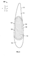
- FIG. 1 is a plan-view of a propeller blade according to one embodiment of the present invention
- FIG. 2 is a cross-section of the propeller blade shown in FIG. 1 ;
- FIG. 3 is a plan-view of a spar core having a groove formed therein.
- FIG. 4 is a plan-view of the spar core of FIG. 3 with the groove filled with a fibrous material.
- FIGs. 1 and 2 plan and cross-section views of a propeller blade 100 according to one embodiment of the present invention are illustrated.
- the direction shown by arrow X shall be referred to as the span wise direction herein
- the direction shown by arrow Y shall be referred to as the chord wise direction herein
- the direction shown by arrow Z shall be referred to as the thickness direction or simply, the thickness.
- the cross-section shown in FIG. 2 is taken along line A-A.
- the blade 100 is formed by first forming a spar 102.
- the spar 102 includes a spar foam core 104 (core) surrounded by a structural layer 106.
- the core 104 is typically formed of a foam material that is injected into a mold to form a particular shape. In other embodiments, the core 104 could be machined to define the desired shape.
- the mold can include a layer of fiberglass or carbon (pre-preg) on the walls thereof to which the foam of the core 104 adheres. As such, the core 104 can be surrounded by a layer (not shown) of fiberglass or carbon in one embodiment but this is not required.
- the foam that forms the core 104 can be selected from one of: polyurethane (PU), polyisocyanurate, or polymethacrylimide (PMI).
- the blade 100 includes one or more ribs 105 formed in the spar foam core 104.
- the ribs 105 serve to provide stiffness in the thickness direction (e.g., from the camber 160 to the face 162 sides) of the propeller blade 100.
- a propeller blade with high activity factor and large chord wise lengths has a lower ratio of stiffness in the chord wise direction as compared to stiffness in the span wise direction.
- the consequences of these secondary bending moments are larges deformations and loadings in the direction perpendicular to the chord (e.g., in direction Z in FIG. 2 ).
- the ribs 105 can provide structure to reduce or avoid these deformations by locally raising inertia and stiffness of the chord wise direction Y of the spar 104.
- the structural layer 106 is typically formed of a dry braided carbon fiber which is subsequently resin injected or a resin-impregnated fabric material (e.g. resin impregnated carbon fiber fabric) and disposed such that it surrounds the core 104 and the ribs 105 (and the fiberglass layer if it is included) by, for example, a braiding process.
- the structural layer 106 is impregnated with a resin.
- the spar 102 is heated to set the resin in the structural layer 106. With the inclusion of the ribs 105, the respective leading and trailing edges 115, 116 of the spar 102 are kept in a fixed relation to one another. As such, the possibility of the core 104 cracking may be reduced.
- the spar 102 is formed such that a portion of it surrounds a root portion 108 that allows the blade 100 to be connected to a hub (not shown). Rotation of the hub causes the blade 100 to rotate and, consequently, causes the generation of thrust to propel an aircraft. In the following discussion, it shall be assumed that the blade 100 rotates in the clockwise direction.
- the root portion 108 is sometimes referred to as a "tulip" in the industry and is typically formed of a metal.
- leading edge foam 112 and trailing edge foam 114 are formed on the leading and trailing edges 115, 116 respectively of the spar 102.
- the leading edge foam 112, trailing edge foam 114 and the spar 102 can then be encased in an outer layer 118.
- the outer layer 118 can be formed of Kevlar® and be in the form of a sock that is pulled over the assembly that includes the leading edge foam 112, trailing edge foam 114 and the spar 102.
- the outer layer 118 could be formed in other manners as well.
- FIG. 3 is a plan view of the camber side 160 of the spar core 104 that forms blade 100.
- the spar core 104 includes a groove 300 formed therein.
- the groove 300 includes a width (w) and a depth (d) that extends into the page.
- the groove 300 can be formed in a many different manners. For instance, the groove 300 could be part of the mold into which the foam forming the spar core 104 is formed.
- the spar core 104 is initially formed without the groove 300 and then the groove 300 is machined or otherwise formed in the core 104.
- the groove 300 causes depressions in the leading and trailing edges 301, 303 of the core 104.
- the groove could be formed such that depressions are only formed in the camber 160 and face 162 sides.
- the groove 300 has had one or more layers of a fibrous material 302 disposed therein.
- the fibrous material 302 is a carbon fiber cloth.
- the fibrous material 302 is formed of the same material as is used to form the structural layer 106 (e.g., a resin impregnated cloth or dry braided carbon fiber or cloth). The resin in the fibrous material 302 is eventually cured and the cured combination of the resin and the fibrous material 302 defines the ribs 105 shown in FIG. 1 .
- the fibrous material 302 could be placed in the groove 300 such that the camber 160 and face 162 sides (including the fibrous material 302) are substantially smooth. That is, the fibrous material 302 can fill the depth (d) of the groove 300 in one embodiment. It shall be understood, that the fibrous material 302 could be formed, for example, by braiding of dry carbon fibers in one embodiment. In another embodiment, the fibrous material 302 is a fibrous cloth and may include resin in it or not.
- groove 300 Only one groove 300 has been shown in FIGs. 3-4 but that is by way of example, not limitation. The number and location of the grooves 300 is a matter of design choice that may be decided by the skill artisan after examination of this disclosure.
- the spar core 104 shown in FIG. 4 can have the structural layer 106 formed over it by first braiding a dry carbon fiber over the spar core 104 and fibrous material 302. A resin can then be injected into the structural layer 106 and the fibrous material 302. In this manner, the material can be made rigid and become the spar ribs 105 described above.
Landscapes
- Engineering & Computer Science (AREA)
- Mechanical Engineering (AREA)
- General Engineering & Computer Science (AREA)
- Life Sciences & Earth Sciences (AREA)
- Sustainable Development (AREA)
- Sustainable Energy (AREA)
- Chemical & Material Sciences (AREA)
- Combustion & Propulsion (AREA)
- Aviation & Aerospace Engineering (AREA)
- Architecture (AREA)
- Moulding By Coating Moulds (AREA)
- Casting Or Compression Moulding Of Plastics Or The Like (AREA)
Abstract
Description
- The present invention relates to propellers and, in particular, to propeller blades that include a rib in the spar core of the propeller blade.
- Modem propeller blades typically include root portions which extend into the hub arm of the hub of the propeller system and which are secured to and rotatable relative to the hub arm via a retention assembly. Typically the retention assembly includes one or a plurality of ball bearing assemblies which permit the rotation of the blade in the hub arm for accomplishing pitch change of the blade for altering the speed of the propeller and accordingly, the aircraft.
- The blades are typically formed by surrounding a foam spar core with a resin impregnated fabric. Leading and trailing edges of the blade are then formed over the fabric and surrounded by, for example, a Kevlar® sock. Such blades are light and effective for their intended purposes.
- According to one embodiment, a propeller blade that includes a foam core having a groove formed therein, a fibrous material filling at least a portion of the groove and a structural layer that surrounds the fibrous material and at least a portion of the foam core is disclosed.
- In another embodiment, a method of forming a propeller blade that includes: forming a foam core, the form core including a groove formed therein; disposing a fibrous material in the groove; and forming a structural layer that surrounds fibrous material and a portion of the foam core is disclosed.
- The subject matter which is regarded as the invention is particularly pointed out and distinctly claimed in the claims at the conclusion of the specification. The foregoing and other features, and advantages of the invention are apparent from the following detailed description taken in conjunction with the accompanying drawings in which:
-
FIG. 1 is a plan-view of a propeller blade according to one embodiment of the present invention; -
FIG. 2 is a cross-section of the propeller blade shown inFIG. 1 ; -
FIG. 3 is a plan-view of a spar core having a groove formed therein; and -
FIG. 4 is a plan-view of the spar core ofFIG. 3 with the groove filled with a fibrous material. - Referring now to
FIGs. 1 and2 , plan and cross-section views of apropeller blade 100 according to one embodiment of the present invention are illustrated. For simplicity, the direction shown by arrow X shall be referred to as the span wise direction herein, the direction shown by arrow Y shall be referred to as the chord wise direction herein and the direction shown by arrow Z shall be referred to as the thickness direction or simply, the thickness. The cross-section shown inFIG. 2 is taken along line A-A. - The
blade 100 is formed by first forming aspar 102. Thespar 102 includes a spar foam core 104 (core) surrounded by astructural layer 106. Thecore 104 is typically formed of a foam material that is injected into a mold to form a particular shape. In other embodiments, thecore 104 could be machined to define the desired shape. The mold can include a layer of fiberglass or carbon (pre-preg) on the walls thereof to which the foam of thecore 104 adheres. As such, thecore 104 can be surrounded by a layer (not shown) of fiberglass or carbon in one embodiment but this is not required. The foam that forms thecore 104 can be selected from one of: polyurethane (PU), polyisocyanurate, or polymethacrylimide (PMI). - According to one embodiment, the
blade 100 includes one ormore ribs 105 formed in thespar foam core 104. A more detailed explanation of theribs 105 is provided below but, in general, theribs 105 serve to provide stiffness in the thickness direction (e.g., from thecamber 160 to theface 162 sides) of thepropeller blade 100. In more detail, a propeller blade with high activity factor and large chord wise lengths, has a lower ratio of stiffness in the chord wise direction as compared to stiffness in the span wise direction. When the curvatures of thecamber 160 and face 162 sides of theblade 100 are high, secondary bending moments may be generated. The consequences of these secondary bending moments are larges deformations and loadings in the direction perpendicular to the chord (e.g., in direction Z inFIG. 2 ). Theribs 105 can provide structure to reduce or avoid these deformations by locally raising inertia and stiffness of the chord wise direction Y of thespar 104. - The
structural layer 106 is typically formed of a dry braided carbon fiber which is subsequently resin injected or a resin-impregnated fabric material (e.g. resin impregnated carbon fiber fabric) and disposed such that it surrounds thecore 104 and the ribs 105 (and the fiberglass layer if it is included) by, for example, a braiding process. In one embodiment, thestructural layer 106 is impregnated with a resin. In some cases, thespar 102 is heated to set the resin in thestructural layer 106. With the inclusion of theribs 105, the respective leading andtrailing edges spar 102 are kept in a fixed relation to one another. As such, the possibility of thecore 104 cracking may be reduced. - In some instances, the
spar 102 is formed such that a portion of it surrounds aroot portion 108 that allows theblade 100 to be connected to a hub (not shown). Rotation of the hub causes theblade 100 to rotate and, consequently, causes the generation of thrust to propel an aircraft. In the following discussion, it shall be assumed that theblade 100 rotates in the clockwise direction. Theroot portion 108 is sometimes referred to as a "tulip" in the industry and is typically formed of a metal. - After the
spar 102 is formed, leadingedge foam 112 andtrailing edge foam 114 are formed on the leading andtrailing edges spar 102. The leadingedge foam 112,trailing edge foam 114 and thespar 102 can then be encased in anouter layer 118. Theouter layer 118 can be formed of Kevlar® and be in the form of a sock that is pulled over the assembly that includes the leadingedge foam 112,trailing edge foam 114 and thespar 102. Of course, theouter layer 118 could be formed in other manners as well. -
FIG. 3 is a plan view of thecamber side 160 of thespar core 104 that formsblade 100. Thespar core 104 includes agroove 300 formed therein. Thegroove 300 includes a width (w) and a depth (d) that extends into the page. Thegroove 300 can be formed in a many different manners. For instance, thegroove 300 could be part of the mold into which the foam forming thespar core 104 is formed. In another embodiment, thespar core 104 is initially formed without thegroove 300 and then thegroove 300 is machined or otherwise formed in thecore 104. As illustrated, thegroove 300 causes depressions in the leading andtrailing edges core 104. Of course, the groove could be formed such that depressions are only formed in thecamber 160 and face 162 sides. - Referring now to
FIG. 4 , thegroove 300 has had one or more layers of afibrous material 302 disposed therein. In one embodiment, thefibrous material 302 is a carbon fiber cloth. In one embodiment, thefibrous material 302 is formed of the same material as is used to form the structural layer 106 (e.g., a resin impregnated cloth or dry braided carbon fiber or cloth). The resin in thefibrous material 302 is eventually cured and the cured combination of the resin and thefibrous material 302 defines theribs 105 shown inFIG. 1 . - The
fibrous material 302 could be placed in thegroove 300 such that thecamber 160 andface 162 sides (including the fibrous material 302) are substantially smooth. That is, thefibrous material 302 can fill the depth (d) of thegroove 300 in one embodiment. It shall be understood, that thefibrous material 302 could be formed, for example, by braiding of dry carbon fibers in one embodiment. In another embodiment, thefibrous material 302 is a fibrous cloth and may include resin in it or not. - Only one
groove 300 has been shown inFIGs. 3-4 but that is by way of example, not limitation. The number and location of thegrooves 300 is a matter of design choice that may be decided by the skill artisan after examination of this disclosure. - In the manner described above, after the
fibrous material 302 has been placed, thespar core 104 shown inFIG. 4 can have thestructural layer 106 formed over it by first braiding a dry carbon fiber over thespar core 104 andfibrous material 302. A resin can then be injected into thestructural layer 106 and thefibrous material 302. In this manner, the material can be made rigid and become thespar ribs 105 described above. - While the invention has been described in detail in connection with only a limited number of embodiments, it should be readily understood that the invention is not limited to such disclosed embodiments. Rather, the invention can be modified to incorporate any number of variations, alterations, substitutions or equivalent arrangements not heretofore described, but which are commensurate with the scope of the invention. Additionally, while the various embodiments of the invention have been described, it is to be understood that aspects of the invention may include only some of the described embodiments. Accordingly, the invention is not to be seen as limited by the foregoing description, but is only limited by the scope of the appended claims.
Claims (13)
- A propeller blade (100) comprising:a foam core (104) having a groove (300) formed therein;a fibrous material (302) filling at least a portion of the groove (300); anda structural layer (106) that surrounds the fibrous material (302) and at least a portion of the foam core (104).
- The propeller blade of claim 1, further comprising:a layer of fiberglass or carbon at least partially disposed between the foam core (104) and the fibrous material (302).
- The propeller blade of claim 1 or 2, wherein the foam core (104) includes a leading edge (301) and a trailing edge (303) and the fibrous material (302) extends from the leading edge (301) to the trailing edge.
- The propeller blade of any preceding claim, wherein the groove (300) has a depth and the fibrous material (302) fills the depth of the groove (300).
- The propeller blade of any preceding claim, further comprising:a root (108) disposed within the structural layer (106) at an end of the propeller blade (100).
- The propeller blade of any preceding claim, wherein the foam core (104) is formed of one or more of: polyurethane (PU), polyisocyanurate, and polymethacrylimide (PMI).
- The propeller blade of any preceding claim, wherein the structural layer (106) is formed of a resin-impregnated fiber material.
- The propeller blade of any preceding claim, wherein the fibrous material (302) is formed of the same material as the structural layer (106).
- The propeller blade of any preceding claim, wherein the fibrous material (302) is formed of carbon fibers.
- The propeller blade of any preceding claim, wherein both the fibrous material (302) and the structural layer (106) have a resin disposed therein.
- A method of forming a propeller blade (100) comprising:forming a foam core (104), the form core (104) including a groove (300) formed therein;disposing a fibrous material (302) in the groove (300); andforming a structural layer (106) that surrounds fibrous material (302) and a portion of the foam core (104).
- The method of claim 11, further comprising:injecting a resin into the fibrous material (302) and the structural layer (106); andcuring the resin.
- The method of claim 11 or 12, wherein forming the foam core (104) includes:forming an initial core in a mold; andmachining the initial mold to form the groove (300).
Priority Applications (2)
| Application Number | Priority Date | Filing Date | Title |
|---|---|---|---|
| EP12305590.7A EP2669192B8 (en) | 2012-05-29 | 2012-05-29 | Propeller blade |
| US13/904,371 US9410434B2 (en) | 2012-05-29 | 2013-05-29 | Propeller blade with spar rib |
Applications Claiming Priority (1)
| Application Number | Priority Date | Filing Date | Title |
|---|---|---|---|
| EP12305590.7A EP2669192B8 (en) | 2012-05-29 | 2012-05-29 | Propeller blade |
Publications (3)
| Publication Number | Publication Date |
|---|---|
| EP2669192A1 true EP2669192A1 (en) | 2013-12-04 |
| EP2669192B1 EP2669192B1 (en) | 2016-11-16 |
| EP2669192B8 EP2669192B8 (en) | 2017-03-01 |
Family
ID=46201520
Family Applications (1)
| Application Number | Title | Priority Date | Filing Date |
|---|---|---|---|
| EP12305590.7A Active EP2669192B8 (en) | 2012-05-29 | 2012-05-29 | Propeller blade |
Country Status (2)
| Country | Link |
|---|---|
| US (1) | US9410434B2 (en) |
| EP (1) | EP2669192B8 (en) |
Cited By (6)
| Publication number | Priority date | Publication date | Assignee | Title |
|---|---|---|---|---|
| EP2910465A1 (en) * | 2014-02-20 | 2015-08-26 | Hamilton Sundstrand Corporation | Propeller blade and method |
| EP2962828A1 (en) * | 2014-06-30 | 2016-01-06 | General Electric Company | Methods of manufacturing rotor blade components for a wind turbine |
| US9574544B2 (en) | 2013-12-16 | 2017-02-21 | General Electric Company | Methods of manufacturing rotor blade components for a wind turbine |
| US9709030B2 (en) | 2013-12-16 | 2017-07-18 | General Electric Company | Methods of manufacturing rotor blade components for a wind turbine |
| CN111120200A (en) * | 2019-12-26 | 2020-05-08 | 薛冻 | Efficient wind driven generator blade |
| CN111742136A (en) * | 2018-02-14 | 2020-10-02 | 乌本产权有限公司 | Method for producing a split rotor blade and rotor blade |
Families Citing this family (5)
| Publication number | Priority date | Publication date | Assignee | Title |
|---|---|---|---|---|
| EP2669192B8 (en) * | 2012-05-29 | 2017-03-01 | Ratier-Figeac SAS | Propeller blade |
| FR3107300B1 (en) * | 2020-02-18 | 2022-07-08 | Safran Aircraft Engines | COMPOSITE BLADE FOR TURBOMACHINE ROTOR |
| EP3907063B1 (en) * | 2020-05-04 | 2024-04-24 | Ratier-Figeac SAS | Multi-layer braided article |
| US11623723B2 (en) | 2020-09-16 | 2023-04-11 | Aerostar International, Llc | Propeller blade assembly |
| US20240151147A1 (en) * | 2022-11-03 | 2024-05-09 | Airfoil And Methods Of Assembly Thereof | Airfoil and methods of assembly thereof |
Citations (2)
| Publication number | Priority date | Publication date | Assignee | Title |
|---|---|---|---|---|
| FR2542695A1 (en) * | 1983-03-18 | 1984-09-21 | Aerospatiale | MULTI-BLADE PROPELLER WITH VARIABLE PITCH WITH BLADES IN COMPOSITE MATERIALS INDIVIDUALLY REMOVABLE, PROCESS FOR MANUFACTURING SUCH BLADES AND BLADES THUS REALIZED |
| EP2317126A2 (en) * | 2009-10-30 | 2011-05-04 | General Electric Company | Methods of manufacture of wind turbine blades and other structures |
Family Cites Families (16)
| Publication number | Priority date | Publication date | Assignee | Title |
|---|---|---|---|---|
| US2767461A (en) * | 1951-03-27 | 1956-10-23 | Lockheed Aircraft Corp | Method of making propeller or rotor blade |
| FR2430354A1 (en) * | 1978-07-07 | 1980-02-01 | Aerospatiale | MULTIPALE PROPELLER WITH VARIABLE STEP OF A SIMPLIFIED TYPE |
| US4302155A (en) * | 1979-01-08 | 1981-11-24 | Hartzell Propeller, Inc. | Air craft propeller assembly with composite blades |
| US4648921A (en) * | 1980-10-02 | 1987-03-10 | United Technologies Corporation | Method of making fiber reinforced articles |
| FR2602739B1 (en) * | 1986-07-28 | 1988-11-18 | Aerospatiale | BLADE OF COMPOSITE MATERIALS, WITH TWO-WELL STRUCTURE AND TWO-WAY BIRTH, AND HAVING A HONEYCOMB SANDWICH COATING, AND METHOD FOR THE PRODUCTION THEREOF |
| FR2617119B1 (en) * | 1987-06-26 | 1989-12-01 | Aerospatiale | BLADE OF COMPOSITE MATERIALS, WITH STRUCTURAL CORE AND PROFILED COVERING COVERING, AND MANUFACTURING METHOD THEREOF |
| US5096384A (en) * | 1990-07-27 | 1992-03-17 | The Marley Cooling Tower Company | Plastic fan blade for industrial cooling towers and method of making same |
| US5127802A (en) * | 1990-12-24 | 1992-07-07 | United Technologies Corporation | Reinforced full-spar composite rotor blade |
| US5222297A (en) * | 1991-10-18 | 1993-06-29 | United Technologies Corporation | Composite blade manufacture |
| FR2740380B1 (en) * | 1995-10-30 | 1998-01-02 | Eurocopter France | METHOD FOR MANUFACTURING A VARIABLE PITCH BLADE FROM COMPOSITE MATERIAL FOR HELICOPTER ROTOR |
| US20110255975A1 (en) * | 2010-04-14 | 2011-10-20 | Arcjet Holdings Llc | Turbines |
| US20130280079A1 (en) * | 2012-04-18 | 2013-10-24 | Hamilton Sundstrand Corporation | Propeller blade with metallic foam spar core |
| EP2660144A1 (en) * | 2012-04-30 | 2013-11-06 | Hamilton Sundstrand Corporation | Propeller blade with modified spar stiffness. |
| EP2669192B8 (en) * | 2012-05-29 | 2017-03-01 | Ratier-Figeac SAS | Propeller blade |
| US9139287B2 (en) * | 2012-06-26 | 2015-09-22 | Hamilton Sundstrand Corporation | Propeller blade with carbon foam spar core |
| US9920629B2 (en) * | 2014-02-20 | 2018-03-20 | Hamilton Sundstrand Corporation | Propeller blade and method |
-
2012
- 2012-05-29 EP EP12305590.7A patent/EP2669192B8/en active Active
-
2013
- 2013-05-29 US US13/904,371 patent/US9410434B2/en active Active
Patent Citations (2)
| Publication number | Priority date | Publication date | Assignee | Title |
|---|---|---|---|---|
| FR2542695A1 (en) * | 1983-03-18 | 1984-09-21 | Aerospatiale | MULTI-BLADE PROPELLER WITH VARIABLE PITCH WITH BLADES IN COMPOSITE MATERIALS INDIVIDUALLY REMOVABLE, PROCESS FOR MANUFACTURING SUCH BLADES AND BLADES THUS REALIZED |
| EP2317126A2 (en) * | 2009-10-30 | 2011-05-04 | General Electric Company | Methods of manufacture of wind turbine blades and other structures |
Cited By (9)
| Publication number | Priority date | Publication date | Assignee | Title |
|---|---|---|---|---|
| US9574544B2 (en) | 2013-12-16 | 2017-02-21 | General Electric Company | Methods of manufacturing rotor blade components for a wind turbine |
| US9709030B2 (en) | 2013-12-16 | 2017-07-18 | General Electric Company | Methods of manufacturing rotor blade components for a wind turbine |
| EP2910465A1 (en) * | 2014-02-20 | 2015-08-26 | Hamilton Sundstrand Corporation | Propeller blade and method |
| US9920629B2 (en) | 2014-02-20 | 2018-03-20 | Hamilton Sundstrand Corporation | Propeller blade and method |
| EP2962828A1 (en) * | 2014-06-30 | 2016-01-06 | General Electric Company | Methods of manufacturing rotor blade components for a wind turbine |
| CN111742136A (en) * | 2018-02-14 | 2020-10-02 | 乌本产权有限公司 | Method for producing a split rotor blade and rotor blade |
| CN111742136B (en) * | 2018-02-14 | 2023-08-18 | 乌本产权有限公司 | Method for producing a split rotor blade and rotor blade |
| US11802541B2 (en) | 2018-02-14 | 2023-10-31 | Wobben Properties Gmbh | Method for producing a split rotor blade, and rotor blade |
| CN111120200A (en) * | 2019-12-26 | 2020-05-08 | 薛冻 | Efficient wind driven generator blade |
Also Published As
| Publication number | Publication date |
|---|---|
| EP2669192B8 (en) | 2017-03-01 |
| US20130323068A1 (en) | 2013-12-05 |
| US9410434B2 (en) | 2016-08-09 |
| EP2669192B1 (en) | 2016-11-16 |
Similar Documents
| Publication | Publication Date | Title |
|---|---|---|
| EP2669192B1 (en) | Propeller blade | |
| EP2660146B1 (en) | Propeller blade with modified spar layup | |
| EP2653380B1 (en) | Propeller blade with internal stiffener | |
| US9429024B2 (en) | Propeller blade with lightweight insert | |
| EP2617555B1 (en) | Wind turbine rotor blade with trailing edge comprising rovings | |
| US10690111B2 (en) | Wind turbine rotor blade | |
| DK201270510A (en) | Rotor blade for a wind turbine and methods of manufacturing the same | |
| EP2647568B1 (en) | Propeller blade with reinforced spar core | |
| US9505486B2 (en) | Propeller blade having compliant adhesive at spar interface | |
| EP2653379B1 (en) | Propeller blade with metallic foam spar core | |
| EP3318484B1 (en) | Reinforced propeller blade and spar | |
| EP2626194A1 (en) | Method of manufacturing a turbine blade, system for manufacturing a turbine blade and intermediate member for manufacturing a turbine blade | |
| EP2660144A1 (en) | Propeller blade with modified spar stiffness. | |
| EP2599713A1 (en) | Propeller blade having a honeycomb spar core | |
| EP2910465B1 (en) | Propeller blade and method | |
| EP2921402A1 (en) | Propeller blade having compliant spar core | |
| US20130287585A1 (en) | Propeller blade with lightweight insert | |
| EP2660143B1 (en) | Propeller blade with lightweight insert and bulkheads | |
| US20180106268A1 (en) | Blade component | |
| JP2012202359A (en) | Wind turbine blade |
Legal Events
| Date | Code | Title | Description |
|---|---|---|---|
| PUAI | Public reference made under article 153(3) epc to a published international application that has entered the european phase |
Free format text: ORIGINAL CODE: 0009012 |
|
| AK | Designated contracting states |
Kind code of ref document: A1 Designated state(s): AL AT BE BG CH CY CZ DE DK EE ES FI FR GB GR HR HU IE IS IT LI LT LU LV MC MK MT NL NO PL PT RO RS SE SI SK SM TR |
|
| AX | Request for extension of the european patent |
Extension state: BA ME |
|
| 17P | Request for examination filed |
Effective date: 20140506 |
|
| RBV | Designated contracting states (corrected) |
Designated state(s): AL AT BE BG CH CY CZ DE DK EE ES FI FR GB GR HR HU IE IS IT LI LT LU LV MC MK MT NL NO PL PT RO RS SE SI SK SM TR |
|
| GRAP | Despatch of communication of intention to grant a patent |
Free format text: ORIGINAL CODE: EPIDOSNIGR1 |
|
| RIC1 | Information provided on ipc code assigned before grant |
Ipc: B64C 11/20 20060101AFI20160520BHEP Ipc: F03D 1/06 20060101ALI20160520BHEP Ipc: B64C 27/473 20060101ALI20160520BHEP |
|
| INTG | Intention to grant announced |
Effective date: 20160622 |
|
| GRAS | Grant fee paid |
Free format text: ORIGINAL CODE: EPIDOSNIGR3 |
|
| GRAA | (expected) grant |
Free format text: ORIGINAL CODE: 0009210 |
|
| AK | Designated contracting states |
Kind code of ref document: B1 Designated state(s): AL AT BE BG CH CY CZ DE DK EE ES FI FR GB GR HR HU IE IS IT LI LT LU LV MC MK MT NL NO PL PT RO RS SE SI SK SM TR |
|
| REG | Reference to a national code |
Ref country code: GB Ref legal event code: FG4D |
|
| REG | Reference to a national code |
Ref country code: CH Ref legal event code: EP |
|
| GRAT | Correction requested after decision to grant or after decision to maintain patent in amended form |
Free format text: ORIGINAL CODE: EPIDOSNCDEC |
|
| REG | Reference to a national code |
Ref country code: IE Ref legal event code: FG4D |
|
| REG | Reference to a national code |
Ref country code: AT Ref legal event code: REF Ref document number: 845647 Country of ref document: AT Kind code of ref document: T Effective date: 20161215 |
|
| REG | Reference to a national code |
Ref country code: DE Ref legal event code: R096 Ref document number: 602012025375 Country of ref document: DE |
|
| RAP2 | Party data changed (patent owner data changed or rights of a patent transferred) |
Owner name: RATIER-FIGEAC SAS |
|
| PG25 | Lapsed in a contracting state [announced via postgrant information from national office to epo] |
Ref country code: LV Free format text: LAPSE BECAUSE OF FAILURE TO SUBMIT A TRANSLATION OF THE DESCRIPTION OR TO PAY THE FEE WITHIN THE PRESCRIBED TIME-LIMIT Effective date: 20161116 |
|
| REG | Reference to a national code |
Ref country code: NL Ref legal event code: MP Effective date: 20161116 |
|
| REG | Reference to a national code |
Ref country code: LT Ref legal event code: MG4D |
|
| REG | Reference to a national code |
Ref country code: AT Ref legal event code: MK05 Ref document number: 845647 Country of ref document: AT Kind code of ref document: T Effective date: 20161116 |
|
| REG | Reference to a national code |
Ref country code: FR Ref legal event code: PLFP Year of fee payment: 6 |
|
| PG25 | Lapsed in a contracting state [announced via postgrant information from national office to epo] |
Ref country code: NO Free format text: LAPSE BECAUSE OF FAILURE TO SUBMIT A TRANSLATION OF THE DESCRIPTION OR TO PAY THE FEE WITHIN THE PRESCRIBED TIME-LIMIT Effective date: 20170216 Ref country code: LT Free format text: LAPSE BECAUSE OF FAILURE TO SUBMIT A TRANSLATION OF THE DESCRIPTION OR TO PAY THE FEE WITHIN THE PRESCRIBED TIME-LIMIT Effective date: 20161116 Ref country code: GR Free format text: LAPSE BECAUSE OF FAILURE TO SUBMIT A TRANSLATION OF THE DESCRIPTION OR TO PAY THE FEE WITHIN THE PRESCRIBED TIME-LIMIT Effective date: 20170217 Ref country code: SE Free format text: LAPSE BECAUSE OF FAILURE TO SUBMIT A TRANSLATION OF THE DESCRIPTION OR TO PAY THE FEE WITHIN THE PRESCRIBED TIME-LIMIT Effective date: 20161116 Ref country code: NL Free format text: LAPSE BECAUSE OF FAILURE TO SUBMIT A TRANSLATION OF THE DESCRIPTION OR TO PAY THE FEE WITHIN THE PRESCRIBED TIME-LIMIT Effective date: 20161116 |
|
| PG25 | Lapsed in a contracting state [announced via postgrant information from national office to epo] |
Ref country code: FI Free format text: LAPSE BECAUSE OF FAILURE TO SUBMIT A TRANSLATION OF THE DESCRIPTION OR TO PAY THE FEE WITHIN THE PRESCRIBED TIME-LIMIT Effective date: 20161116 Ref country code: PL Free format text: LAPSE BECAUSE OF FAILURE TO SUBMIT A TRANSLATION OF THE DESCRIPTION OR TO PAY THE FEE WITHIN THE PRESCRIBED TIME-LIMIT Effective date: 20161116 Ref country code: ES Free format text: LAPSE BECAUSE OF FAILURE TO SUBMIT A TRANSLATION OF THE DESCRIPTION OR TO PAY THE FEE WITHIN THE PRESCRIBED TIME-LIMIT Effective date: 20161116 Ref country code: PT Free format text: LAPSE BECAUSE OF FAILURE TO SUBMIT A TRANSLATION OF THE DESCRIPTION OR TO PAY THE FEE WITHIN THE PRESCRIBED TIME-LIMIT Effective date: 20170316 Ref country code: HR Free format text: LAPSE BECAUSE OF FAILURE TO SUBMIT A TRANSLATION OF THE DESCRIPTION OR TO PAY THE FEE WITHIN THE PRESCRIBED TIME-LIMIT Effective date: 20161116 Ref country code: AT Free format text: LAPSE BECAUSE OF FAILURE TO SUBMIT A TRANSLATION OF THE DESCRIPTION OR TO PAY THE FEE WITHIN THE PRESCRIBED TIME-LIMIT Effective date: 20161116 Ref country code: RS Free format text: LAPSE BECAUSE OF FAILURE TO SUBMIT A TRANSLATION OF THE DESCRIPTION OR TO PAY THE FEE WITHIN THE PRESCRIBED TIME-LIMIT Effective date: 20161116 |
|
| PG25 | Lapsed in a contracting state [announced via postgrant information from national office to epo] |
Ref country code: DK Free format text: LAPSE BECAUSE OF FAILURE TO SUBMIT A TRANSLATION OF THE DESCRIPTION OR TO PAY THE FEE WITHIN THE PRESCRIBED TIME-LIMIT Effective date: 20161116 Ref country code: EE Free format text: LAPSE BECAUSE OF FAILURE TO SUBMIT A TRANSLATION OF THE DESCRIPTION OR TO PAY THE FEE WITHIN THE PRESCRIBED TIME-LIMIT Effective date: 20161116 Ref country code: RO Free format text: LAPSE BECAUSE OF FAILURE TO SUBMIT A TRANSLATION OF THE DESCRIPTION OR TO PAY THE FEE WITHIN THE PRESCRIBED TIME-LIMIT Effective date: 20161116 Ref country code: CZ Free format text: LAPSE BECAUSE OF FAILURE TO SUBMIT A TRANSLATION OF THE DESCRIPTION OR TO PAY THE FEE WITHIN THE PRESCRIBED TIME-LIMIT Effective date: 20161116 Ref country code: SK Free format text: LAPSE BECAUSE OF FAILURE TO SUBMIT A TRANSLATION OF THE DESCRIPTION OR TO PAY THE FEE WITHIN THE PRESCRIBED TIME-LIMIT Effective date: 20161116 |
|
| REG | Reference to a national code |
Ref country code: DE Ref legal event code: R097 Ref document number: 602012025375 Country of ref document: DE |
|
| PG25 | Lapsed in a contracting state [announced via postgrant information from national office to epo] |
Ref country code: LU Free format text: LAPSE BECAUSE OF NON-PAYMENT OF DUE FEES Effective date: 20170531 Ref country code: BE Free format text: LAPSE BECAUSE OF FAILURE TO SUBMIT A TRANSLATION OF THE DESCRIPTION OR TO PAY THE FEE WITHIN THE PRESCRIBED TIME-LIMIT Effective date: 20161116 Ref country code: SM Free format text: LAPSE BECAUSE OF FAILURE TO SUBMIT A TRANSLATION OF THE DESCRIPTION OR TO PAY THE FEE WITHIN THE PRESCRIBED TIME-LIMIT Effective date: 20161116 Ref country code: IT Free format text: LAPSE BECAUSE OF FAILURE TO SUBMIT A TRANSLATION OF THE DESCRIPTION OR TO PAY THE FEE WITHIN THE PRESCRIBED TIME-LIMIT Effective date: 20161116 Ref country code: BG Free format text: LAPSE BECAUSE OF FAILURE TO SUBMIT A TRANSLATION OF THE DESCRIPTION OR TO PAY THE FEE WITHIN THE PRESCRIBED TIME-LIMIT Effective date: 20170216 |
|
| PLBE | No opposition filed within time limit |
Free format text: ORIGINAL CODE: 0009261 |
|
| STAA | Information on the status of an ep patent application or granted ep patent |
Free format text: STATUS: NO OPPOSITION FILED WITHIN TIME LIMIT |
|
| 26N | No opposition filed |
Effective date: 20170817 |
|
| PG25 | Lapsed in a contracting state [announced via postgrant information from national office to epo] |
Ref country code: SI Free format text: LAPSE BECAUSE OF FAILURE TO SUBMIT A TRANSLATION OF THE DESCRIPTION OR TO PAY THE FEE WITHIN THE PRESCRIBED TIME-LIMIT Effective date: 20161116 |
|
| REG | Reference to a national code |
Ref country code: DE Ref legal event code: R119 Ref document number: 602012025375 Country of ref document: DE |
|
| REG | Reference to a national code |
Ref country code: CH Ref legal event code: PL |
|
| PG25 | Lapsed in a contracting state [announced via postgrant information from national office to epo] |
Ref country code: MC Free format text: LAPSE BECAUSE OF FAILURE TO SUBMIT A TRANSLATION OF THE DESCRIPTION OR TO PAY THE FEE WITHIN THE PRESCRIBED TIME-LIMIT Effective date: 20161116 |
|
| REG | Reference to a national code |
Ref country code: IE Ref legal event code: MM4A |
|
| PG25 | Lapsed in a contracting state [announced via postgrant information from national office to epo] |
Ref country code: CH Free format text: LAPSE BECAUSE OF NON-PAYMENT OF DUE FEES Effective date: 20170531 Ref country code: LI Free format text: LAPSE BECAUSE OF NON-PAYMENT OF DUE FEES Effective date: 20170531 |
|
| PG25 | Lapsed in a contracting state [announced via postgrant information from national office to epo] |
Ref country code: LU Free format text: LAPSE BECAUSE OF NON-PAYMENT OF DUE FEES Effective date: 20170529 |
|
| PG25 | Lapsed in a contracting state [announced via postgrant information from national office to epo] |
Ref country code: IE Free format text: LAPSE BECAUSE OF NON-PAYMENT OF DUE FEES Effective date: 20170529 Ref country code: DE Free format text: LAPSE BECAUSE OF NON-PAYMENT OF DUE FEES Effective date: 20171201 |
|
| REG | Reference to a national code |
Ref country code: FR Ref legal event code: PLFP Year of fee payment: 7 |
|
| PG25 | Lapsed in a contracting state [announced via postgrant information from national office to epo] |
Ref country code: MT Free format text: LAPSE BECAUSE OF NON-PAYMENT OF DUE FEES Effective date: 20170529 |
|
| PG25 | Lapsed in a contracting state [announced via postgrant information from national office to epo] |
Ref country code: HU Free format text: LAPSE BECAUSE OF FAILURE TO SUBMIT A TRANSLATION OF THE DESCRIPTION OR TO PAY THE FEE WITHIN THE PRESCRIBED TIME-LIMIT; INVALID AB INITIO Effective date: 20120529 |
|
| PG25 | Lapsed in a contracting state [announced via postgrant information from national office to epo] |
Ref country code: CY Free format text: LAPSE BECAUSE OF NON-PAYMENT OF DUE FEES Effective date: 20161116 |
|
| PG25 | Lapsed in a contracting state [announced via postgrant information from national office to epo] |
Ref country code: MK Free format text: LAPSE BECAUSE OF FAILURE TO SUBMIT A TRANSLATION OF THE DESCRIPTION OR TO PAY THE FEE WITHIN THE PRESCRIBED TIME-LIMIT Effective date: 20161116 |
|
| PG25 | Lapsed in a contracting state [announced via postgrant information from national office to epo] |
Ref country code: TR Free format text: LAPSE BECAUSE OF FAILURE TO SUBMIT A TRANSLATION OF THE DESCRIPTION OR TO PAY THE FEE WITHIN THE PRESCRIBED TIME-LIMIT Effective date: 20161116 |
|
| PG25 | Lapsed in a contracting state [announced via postgrant information from national office to epo] |
Ref country code: AL Free format text: LAPSE BECAUSE OF FAILURE TO SUBMIT A TRANSLATION OF THE DESCRIPTION OR TO PAY THE FEE WITHIN THE PRESCRIBED TIME-LIMIT Effective date: 20161116 Ref country code: IS Free format text: LAPSE BECAUSE OF FAILURE TO SUBMIT A TRANSLATION OF THE DESCRIPTION OR TO PAY THE FEE WITHIN THE PRESCRIBED TIME-LIMIT Effective date: 20170316 |
|
| PGFP | Annual fee paid to national office [announced via postgrant information from national office to epo] |
Ref country code: GB Payment date: 20240419 Year of fee payment: 13 |
|
| PGFP | Annual fee paid to national office [announced via postgrant information from national office to epo] |
Ref country code: FR Payment date: 20240418 Year of fee payment: 13 |