EP2669155B1 - Anhänger-Rangierantrieb mit Getriebe mit nicht paralleler Achsanordnung - Google Patents
Anhänger-Rangierantrieb mit Getriebe mit nicht paralleler Achsanordnung Download PDFInfo
- Publication number
- EP2669155B1 EP2669155B1 EP13168269.2A EP13168269A EP2669155B1 EP 2669155 B1 EP2669155 B1 EP 2669155B1 EP 13168269 A EP13168269 A EP 13168269A EP 2669155 B1 EP2669155 B1 EP 2669155B1
- Authority
- EP
- European Patent Office
- Prior art keywords
- drive
- rotation
- axis
- drive roller
- trailer
- Prior art date
- Legal status (The legal status is an assumption and is not a legal conclusion. Google has not performed a legal analysis and makes no representation as to the accuracy of the status listed.)
- Active
Links
- 230000005540 biological transmission Effects 0.000 claims description 58
- 230000033001 locomotion Effects 0.000 claims description 36
- 230000008878 coupling Effects 0.000 claims description 4
- 238000010168 coupling process Methods 0.000 claims description 4
- 238000005859 coupling reaction Methods 0.000 claims description 4
- 238000013016 damping Methods 0.000 claims description 3
- 230000008901 benefit Effects 0.000 description 4
- 238000010276 construction Methods 0.000 description 3
- 230000007246 mechanism Effects 0.000 description 2
- 230000003466 anti-cipated effect Effects 0.000 description 1
- 230000004323 axial length Effects 0.000 description 1
- 230000000903 blocking effect Effects 0.000 description 1
- 230000008859 change Effects 0.000 description 1
- 230000001419 dependent effect Effects 0.000 description 1
- 239000000446 fuel Substances 0.000 description 1
- 238000000265 homogenisation Methods 0.000 description 1
- 238000004519 manufacturing process Methods 0.000 description 1
- 238000005259 measurement Methods 0.000 description 1
- 230000009467 reduction Effects 0.000 description 1
- 239000006228 supernatant Substances 0.000 description 1
Images


Classifications
-
- B—PERFORMING OPERATIONS; TRANSPORTING
- B62—LAND VEHICLES FOR TRAVELLING OTHERWISE THAN ON RAILS
- B62D—MOTOR VEHICLES; TRAILERS
- B62D59/00—Trailers with driven ground wheels or the like
- B62D59/04—Trailers with driven ground wheels or the like driven from propulsion unit on trailer
-
- B—PERFORMING OPERATIONS; TRANSPORTING
- B25—HAND TOOLS; PORTABLE POWER-DRIVEN TOOLS; MANIPULATORS
- B25B—TOOLS OR BENCH DEVICES NOT OTHERWISE PROVIDED FOR, FOR FASTENING, CONNECTING, DISENGAGING OR HOLDING
- B25B5/00—Clamps
- B25B5/06—Arrangements for positively actuating jaws
- B25B5/061—Arrangements for positively actuating jaws with fluid drive
- B25B5/064—Arrangements for positively actuating jaws with fluid drive with clamping means pivoting around an axis perpendicular to the pressing direction
-
- B—PERFORMING OPERATIONS; TRANSPORTING
- B25—HAND TOOLS; PORTABLE POWER-DRIVEN TOOLS; MANIPULATORS
- B25J—MANIPULATORS; CHAMBERS PROVIDED WITH MANIPULATION DEVICES
- B25J15/00—Gripping heads and other end effectors
- B25J15/02—Gripping heads and other end effectors servo-actuated
- B25J15/0206—Gripping heads and other end effectors servo-actuated comprising articulated grippers
- B25J15/0226—Gripping heads and other end effectors servo-actuated comprising articulated grippers actuated by cams
-
- F—MECHANICAL ENGINEERING; LIGHTING; HEATING; WEAPONS; BLASTING
- F15—FLUID-PRESSURE ACTUATORS; HYDRAULICS OR PNEUMATICS IN GENERAL
- F15B—SYSTEMS ACTING BY MEANS OF FLUIDS IN GENERAL; FLUID-PRESSURE ACTUATORS, e.g. SERVOMOTORS; DETAILS OF FLUID-PRESSURE SYSTEMS, NOT OTHERWISE PROVIDED FOR
- F15B15/00—Fluid-actuated devices for displacing a member from one position to another; Gearing associated therewith
- F15B15/02—Mechanical layout characterised by the means for converting the movement of the fluid-actuated element into movement of the finally-operated member
-
- F—MECHANICAL ENGINEERING; LIGHTING; HEATING; WEAPONS; BLASTING
- F15—FLUID-PRESSURE ACTUATORS; HYDRAULICS OR PNEUMATICS IN GENERAL
- F15B—SYSTEMS ACTING BY MEANS OF FLUIDS IN GENERAL; FLUID-PRESSURE ACTUATORS, e.g. SERVOMOTORS; DETAILS OF FLUID-PRESSURE SYSTEMS, NOT OTHERWISE PROVIDED FOR
- F15B15/00—Fluid-actuated devices for displacing a member from one position to another; Gearing associated therewith
- F15B15/08—Characterised by the construction of the motor unit
- F15B15/14—Characterised by the construction of the motor unit of the straight-cylinder type
- F15B15/149—Fluid interconnections, e.g. fluid connectors, passages
-
- B—PERFORMING OPERATIONS; TRANSPORTING
- B21—MECHANICAL METAL-WORKING WITHOUT ESSENTIALLY REMOVING MATERIAL; PUNCHING METAL
- B21D—WORKING OR PROCESSING OF SHEET METAL OR METAL TUBES, RODS OR PROFILES WITHOUT ESSENTIALLY REMOVING MATERIAL; PUNCHING METAL
- B21D43/00—Feeding, positioning or storing devices combined with, or arranged in, or specially adapted for use in connection with, apparatus for working or processing sheet metal, metal tubes or metal profiles; Associations therewith of cutting devices
- B21D43/02—Advancing work in relation to the stroke of the die or tool
- B21D43/04—Advancing work in relation to the stroke of the die or tool by means in mechanical engagement with the work
- B21D43/10—Advancing work in relation to the stroke of the die or tool by means in mechanical engagement with the work by grippers
-
- F—MECHANICAL ENGINEERING; LIGHTING; HEATING; WEAPONS; BLASTING
- F15—FLUID-PRESSURE ACTUATORS; HYDRAULICS OR PNEUMATICS IN GENERAL
- F15B—SYSTEMS ACTING BY MEANS OF FLUIDS IN GENERAL; FLUID-PRESSURE ACTUATORS, e.g. SERVOMOTORS; DETAILS OF FLUID-PRESSURE SYSTEMS, NOT OTHERWISE PROVIDED FOR
- F15B15/00—Fluid-actuated devices for displacing a member from one position to another; Gearing associated therewith
- F15B15/08—Characterised by the construction of the motor unit
- F15B15/14—Characterised by the construction of the motor unit of the straight-cylinder type
- F15B15/1423—Component parts; Constructional details
- F15B15/1457—Piston rods
Definitions
- the invention relates to a shunting drive for a trailer, especially for caravans, boat trailers, horse trailers, market trailers, load trailers and. ⁇ ., According to the preamble of claim 1.
- Trailers are usually towed by tractors. So it is known that a car can pull a caravan. When the trailer is removed from the tractor, it is usually pushed by hand into the final position.
- trailers are increasingly offered in the caravan area, which can be moved only with difficulty by hand due to their size and thus their weight. Therefore, shunting or auxiliary drives have been developed that make it possible. to move or turn a trailer even without tractor with engine assistance.
- the shunting drive has a relative to a chassis of the trailer movable carrier, which carries a drive motor and a drive roller.
- a moving mechanism serves to move the carrier between a rest position in which the drive roller is separated from a wheel of the trailer, and a drive position in which the drive roller is pressed against the wheel of the trailer.
- the drive motor drives the drive roller via a gear having a worm wheel, wherein the axes of rotation of the drive motor and drive roller are perpendicular to each other.
- the invention has for its object to provide a maneuver for a trailer, which has an improved drive concept, which also can be realized as compact as possible.
- a maneuvering drive for a trailer comprising a fastening device for fastening to the trailer, a carrier movable relative to the fastening device, a drive motor held by the carrier, and a drive roller rotatably drivable by the drive motor, is characterized in that the axis of rotation of the drive motor is inclined extends to the axis of rotation of the drive roller, that is at an oblique angle to the axis of rotation of the drive roller.
- a movement device is provided for moving the carrier between a rest position in which the drive roller is separated from a wheel of the trailer, and a drive position in which the drive roller is pressed against the wheel of the trailer.
- the maneuvering drive typically has the relative to the fastening device movable carrier, which supports the drive motor and the drive roller or bearings. With the aid of the movement device, the carrier can be moved back and forth between the rest position and the drive position, so that the drive roller is pressed against the wheel of the trailer, if necessary, in particular against the running surface of the trailer wheel or lifted off the wheel.
- This structure is for example from the EP 1 7 14 858 A1 known.
- the inclination of the axes of rotation may mean that the axes of rotation lie in a common horizontal plane, but are inclined to each other. It is also possible that one or both axes of rotation also extend with a vertical component, so that the axes of rotation are skewed to each other, so a kind of spatial skew is achieved. For example, one of the axes of rotation may lie exclusively in a horizontal plane, while the other axis of rotation extends in both horizontal and vertical directions.
- the inclination of the rotary axes is achieved such that the angle between the drive motor rotation axis (the rotation axis of the drive motor) and the drive roller rotation axis (the rotation axis of the drive roller) is greater than 0 °, so that the axes of rotation are not parallel to each other.
- the parallel arrangement of the axes of rotation in the prior art leads to a relatively wide, massive Rangierantrieb with an increased space requirement.
- the inclination of the axes of rotation is also achieved in that the angle between the drive motor axis of rotation and the drive roller axis of rotation is not equal to 90 °, so that the axes of rotation are not perpendicular to each other.
- the Rangierantrieb is indeed designed relatively slim.
- the slender construction requires an elongated design that requires appropriate space.
- an "oblique" arrangement of the axes means that the axes are not at an angle of 0 ° or 90 ° to each other.
- the angle may be in a range between 1 ° and 89 °, preferably between 2 ° and 88 °.
- the angular position requires a suitable selection and design of the necessary transmission device, as will be explained later.
- the inclination should exist especially in the rest position, ie in the unloaded state.
- the drive roller may be mounted on one side of the carrier.
- a transmission device may be provided. With the help of the transmission device, the drive power of the drive motor is transmitted to the drive roller.
- the usually high engine speed can be reduced in order to convert it into a suitable speed for the drive roller.
- the drive torque of the motor is increased so that the drive roller can powerfully move its associated trailer wheel.
- the transmission device may be held by the carrier.
- the carrier may simultaneously form part of the transmission housing, such that the carrier and the transmission housing are integrated into an assembly.
- the transmission device may comprise at least one component selected from the group of spur gear, bevel gear, crown wheel, worm wheel, hypoid, double gear, integral double gear. Depending on the angular position between the axis of rotation of the drive motor and the axis of rotation of the drive roller thus a suitable transmission can be constructed, with different components can be combined.
- a straight toothing or a helical toothing can be used.
- spur and bevel gear stages can be advantageous because they allow the construction of gears with high efficiency.
- a worm wheel has a much lower efficiency, which may be so low under certain circumstances that the transmission is self-locking.
- This in turn has the advantage that no additional braking device must be provided in order to use the Rangierantrieb for braking and holding the associated trailer wheel.
- gear transmission As an alternative to a gear transmission, other types of transmission may be used, such as a belt transmission.
- the drive motor has a drive shaft which extends along the drive motor rotation axis.
- the drive roller has a roller shaft extending along the drive roller rotation axis.
- the transmission device may have at least one intermediate stage with a transmission shaft, wherein the transmission shaft is arranged parallel to the drive shaft or parallel to the roller shaft.
- the transmission shaft can be arranged between the drive shaft and the roller shaft.
- Rangierantriebs can be tilted with respect to the main direction of the Rangierantriebs, which are suitable for technical or design reasons.
- the main direction of the Rangierantriebs can also be understood that direction which corresponds to the longitudinal direction of the trailer to which the Rangierantrieb is to be attached.
- the carrier can be reciprocated by the movement device on a movement axis between the rest position and the drive position.
- the drive roller rotation axis perpendicular to the movement axis and the drive motor rotation axis are inclined to the movement axis or at a second variant, the drive roller rotation axis obliquely to the movement axis and the drive motor rotation axis are perpendicular or parallel to the movement axis.
- both axes of rotation, both the drive roller rotation axis and the drive motor rotation axis are inclined to the movement axis.
- the movement axis may also be an axis to which at least one axis of rotation of a component of the transmission device is perpendicular. In this way, for example, both the drive motor and the drive roller can be aligned obliquely to the gear unit or components of the gear unit.
- the two axes of rotation and the axis of motion can each lie in a horizontal plane.
- at least one of the axes of rotation and / or the movement axis can extend out of the horizontal plane, ie also with a vertical component.
- the relevant axis runs at an oblique angle to the horizontal plane, so that a spatial inclination is achieved.
- the drive roller rotation axis is only minimally oblique to the remaining components, in particular only minimally oblique to the axis of movement of the carrier.
- the angle of the drive roller rotation axis can in this case z. B. only a few degrees, e.g. 1 to 4 ° deviate from a vertical arrangement between the drive roller rotation axis and the movement axis.
- the drive motor may be, for example, a universal motor or a brushless electric motor.
- a brushless electric motor with external rotor (external rotor motor) may be appropriate because it allows a particularly compact design.
- the axial length of such an external rotor motor is low and thus increases the compactness.
- An external rotor motor also has the advantage that it generates a higher torque than an internal rotor motor.
- the speed of the motor can be reduced, which is advantageous for the interpretation of the required between the drive motor and the drive roller gear device, in particular for the requirement of the gear ratios. Due to the design of an external rotor motor, the construction volume and weight can be noticeably reduced.
- the braking device may, in particular, act directly on the drive motor, its drive shaft (motor shaft) or, for example, on the external rotor and cause the drive roller to decelerate by braking the drive shaft or the external rotor.
- the braking device can be arranged frontally to the drive motor. Additionally or alternatively, the braking device may be attached to the external rotor so as to prevent rotation of the motor or the external rotor, which consequently also leads to a blockage of the drive roller.
- the braking device acts elsewhere, for example in the transmission device, in order to achieve a braking or blocking of the drive roller.
- a coupling for vibration damping is provided between the engine and the transmission.
- This usually includes a damping rubber element between the input and the output side, which can be compensated for any imbalances or misalignments and noise can be avoided.
- the coupling can also be designed as a bellows coupling.
- the drive roller may have over its axial extent a variable outer contour, such that the diameter of the drive roller is greater in the region of its axial center than at its axial edges. If the drive roller thus has a slightly larger diameter in the middle than at the edges, ie, for example, has a convex shape, it can penetrate slightly deeper on the running surface of the trailer than at the edges. However, since the tread of the trailer is inherently softer than the rather stiffer flanks of the trailer, a total uniform contact pressure distribution between the drive roller and trailer can be achieved in this way.
- the drive roller rotation axis may be oblique to the axis of rotation of the trailer wheel, with at least a portion of the drive roller protruding toward the wheel in the region facing the wheel of the trailer in front of other components, particularly in front of the carrier or transmission housing, such that upon movement of the carrier with the drive roller from the rest position to the drive position, the relevant part of the drive roller first comes in contact with the wheel of the trailer, namely before the other component concerned can come into contact with the wheel.
- the so-called Störkanten problem can be counteracted. If the component in question, ie in particular a part of the carrier or the gear housing protrudes forward in the direction of the trailer, depending on the dimensions of the trailer and the arrangement of Rangierantriebs the risk. that the component rubs or grinds on the trailer wheel. With the inclination of the drive roller rotation axis is achieved that at least a part of the drive roller protrudes forward, in the direction of the trailer wheel, even beyond the other components. As a result, this part of the drive roller first comes into contact with the trailer wheel. Since the drive roller has already reached its drive position in this situation, the carrier can not be moved further in the direction of the trailer wheel, so that no further components can be pressed against the trailer.
- Fig. 1 shows a perspective view of a Rangierantrieb with a drive motor 1 and a drive of the drive motor 1 rotatably driven drive roller 2.
- the drive motor 1 and the drive roller 2 are held by a carrier 3. Inside the carrier 3, a transmission device 4 is arranged, which serves to translate the relatively high speed of the drive motor 1 in a lower speed for the drive roller 2.
- the transmission device 4 is in Fig. 1 shown only from the outside. In particular, the transmission device 4 may have several stages. to achieve the desired total gear ratio.
- the carrier 3 is held by a fastening device 5, which in turn can be attached to a chassis, not shown, of a trailer.
- the attachment means 5 may be in the form of a square tube which may be slid onto a corresponding cross tube (not shown), the cross tube being in turn attached to the underside of the trailer.
- the fastening device 5 can also have a holder 5a which carries the carrier 3.
- the carrier 3 is then movable relative to the holder 5a back and forth.
- the holder 5a has a suitable linear guide in order to enable a linear movement of the carrier 3.
- the carrier 3 is linearly reciprocable relative to the fastening device 5 by means of a movement device, not shown, linearly. In this way, the carrier 3 between a rest position, in which the drive roller 2 is separated from a wheel 6 of the trailer, and a drive position in which the drive roller 2 is pressed against the wheel 6 of the trailer - as in Fig. 1 shown - moved back and forth.
- the movement device can, for. B. have a spindle drive to allow the movement of the carrier 3.
- the carrier 3 is reciprocable along the movement axis X in a straight or curved path together with the drive motor 1 and the drive roller 2 as well as the transmission device 4 in order to be displaceable between the rest position and the drive position.
- the axis of rotation 1a of the drive motor 1 and the axis of rotation 2a of the drive roller 2 extend at an oblique angle to each other, which will be explained later with reference to further figures.
- the axes of rotation 1 a, 2 a of drive motor 1 and drive roller 2 are not parallel to each other, but at an oblique angle.
- the angular position can be relatively low and be, for example, only a few degrees. By the angular position is achieved, inter alia, that spur gears, which are provided in the transmission device 4, produce less noise, so that the Rangierantrieb allows low-noise operation.
- the angle compensation of the drive roller rotation axis can also be supported by the fact that the drive roller 2 has a slightly domed shape.
- the drive roller 2 in the region of its axial center 2b have a larger diameter than at their axial edges or ends.
- the inclination of the axes of rotation 1 a, 2 a of drive motor 1 and drive roller 2 is in the Rangierantrieb of Fig. 1 so small that it is not readily apparent in the figure.
- the angle between the axes of rotation 1 a and 2a is slightly above 0 ° and is in the example shown 1.5 °.
- the angular position between the drive motor and the drive shaft can - depending on the configuration - be larger and accordingly take larger angles. Only the angular position 90 °, as for example from the EP 1 7 14 858 A1 is known, is not regarded as oblique angular position.
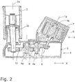
- Fig. 2 shows in sectional view an example of an embodiment of the Rangierantriebs of Fig. 1 ,
- a rotation axis 1a of the drive motor 1 is at an oblique angle to a rotation axis 2a of the drive roller 2.
- the angle in the example shown is about 40 to 45 °. As stated above, it can also be significantly larger or smaller.
- the drive motor 1 is designed as a brushless external rotor motor, with an inner stator 6 and an outer rotor 7.
- the outer rotor 7 is coupled to a drive shaft 1 b of the drive motor 1.
- Both the drive motor 1 and the drive roller 2 are mounted or held on the carrier 3.
- the carrier 3 serves equally as a gear housing for the transmission device 4th
- the transmission device 4 has three stages of reduction.
- the axes 4a of the transmission device 4 are parallel to the axis of rotation 2a of the drive roller 2 and thus at an oblique angle to the axis of rotation 1a of the drive motor.
- the first gear 8 is to be designed such that a power transmission over an oblique angle is possible.
- an in Fig. 2 only schematically illustrated bevel gear.
- alternative It is also possible to use an inclined spur gear or a hypoid stage.
- spur gears can be used.
- the transmission device 4 and double gears (for example, for the second gear stage 9 and the third gear stage 1 0) can be used, so gears in which two gears are arranged on a common axis.
- the double gears can be made in one piece or in one piece.
- the transmission device finally drives a drive shaft of the drive roller 2 (roller shaft 2c).
- a brake device On the drive motor 1, in particular on the external rotor 7 of the drive motor 1, a brake device, not shown, may be provided to brake or block the drive motor 1 and thus also the drive roller 2.
- Fig. 3 shows a variant of the embodiment of Fig. 2 .
- Fig. 3 are also the axis of rotation 1a of the drive motor. 1 and the axis of rotation 2a of the drive roller 2 are arranged at an oblique angle to each other.
- the rotation axis 1a of the drive motor 1 and the rotation axes 4a of the transmission device 4 are aligned parallel to each other, while the rotation axis 2a of the drive roller 2 is also angled or inclined to the axes 4a of the transmission components.
- the inclination of the axis of rotation 2a of the drive roller 2 can deviate only very slightly from a parallel arrangement of the axis of rotation 2a of the drive roller 2 to the axis of rotation 1a of the drive motor 1, as already explained above.
- the skew angle can be e.g. only in a range of 1 to 3 °.
- the transmission device 4 of Fig. 3 is also like the transmission device 4 of Fig. 2 adapted to move the rotational movement of the drive motor 1 in terms of the rotational speed and the torque in a suitable rotational movement for the drive roller 2.
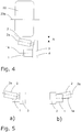
- Fig. 4 serves to clarify the so-called Störkanten problem.
- the axis of rotation 2a of the drive roller 2 is oblique to the axis of rotation 1a of the drive motor and also obliquely to the axis of rotation 20a of the wheel 20th
- Fig. 5 shows in a schematic front view ( Fig. 5a ) and rear view ( Fig. 5b ) A variant of the Rangierantriebs with inclined drive roller.
- the axis of rotation 2a of the drive roller 2 with a vertical component, here upwards, obliquely, while the axis of rotation 1a of the drive motor 1 is completely in a horizontal plane.
- the axis of rotation 1 a of the drive motor 1 is inclined with a vertical component up or down, while the drive roller 2 is completely in the horizontal.
- the horizontal components of the extensions of the axes of rotation 1 a, 2 a are at an oblique angle to each other.
Landscapes
- Engineering & Computer Science (AREA)
- Mechanical Engineering (AREA)
- General Engineering & Computer Science (AREA)
- Physics & Mathematics (AREA)
- Fluid Mechanics (AREA)
- Chemical & Material Sciences (AREA)
- Robotics (AREA)
- Combustion & Propulsion (AREA)
- Transportation (AREA)
- Gear Transmission (AREA)
- Arrangement Or Mounting Of Propulsion Units For Vehicles (AREA)
- Automobile Manufacture Line, Endless Track Vehicle, Trailer (AREA)
- Connection Of Motors, Electrical Generators, Mechanical Devices, And The Like (AREA)
Applications Claiming Priority (1)
| Application Number | Priority Date | Filing Date | Title |
|---|---|---|---|
| DE102012010547.9A DE102012010547B4 (de) | 2012-05-29 | 2012-05-29 | Rangierantrieb für einen Anhänger |
Publications (3)
| Publication Number | Publication Date |
|---|---|
| EP2669155A2 EP2669155A2 (de) | 2013-12-04 |
| EP2669155A3 EP2669155A3 (de) | 2014-05-21 |
| EP2669155B1 true EP2669155B1 (de) | 2017-01-04 |
Family
ID=48444213
Family Applications (1)
| Application Number | Title | Priority Date | Filing Date |
|---|---|---|---|
| EP13168269.2A Active EP2669155B1 (de) | 2012-05-29 | 2013-05-17 | Anhänger-Rangierantrieb mit Getriebe mit nicht paralleler Achsanordnung |
Country Status (3)
| Country | Link |
|---|---|
| EP (1) | EP2669155B1 (da) |
| DE (2) | DE102012010547B4 (da) |
| DK (1) | DK2669155T3 (da) |
Families Citing this family (5)
| Publication number | Priority date | Publication date | Assignee | Title |
|---|---|---|---|---|
| DE202015105911U1 (de) * | 2015-11-05 | 2016-01-12 | Truma Gerätetechnik GmbH & Co. KG | Rangierantrieb für einen Anhänger |
| AU201712794S (en) | 2016-11-23 | 2017-05-23 | Dometic Sweden Ab | Ventilation and air conditioning apparatus |
| DE112018005883T5 (de) | 2017-11-16 | 2020-07-30 | Dometic Sweden Ab | Klimatisierungsvorrichtung für wohnmobile |
| USD905217S1 (en) | 2018-09-05 | 2020-12-15 | Dometic Sweden Ab | Air conditioning apparatus |
| DE102019205987B4 (de) * | 2019-04-26 | 2022-05-05 | Zf Friedrichshafen Ag | Elektrischer Achsantrieb für ein Fahrzeug |
Family Cites Families (7)
| Publication number | Priority date | Publication date | Assignee | Title |
|---|---|---|---|---|
| DE20213534U1 (de) * | 2002-08-29 | 2004-03-04 | Truma Gerätetechnik GmbH & Co. KG | Hilfsantrieb für fremdbewegte Fahrzeuge, insbesondere Anhänger |
| NL1022672C2 (nl) * | 2003-02-13 | 2004-08-16 | Reich Kg | Manoeuvreerinrichting voor niet aangedreven wagens. |
| DE502005003313D1 (de) * | 2005-04-18 | 2008-04-30 | Truma Geraetetechnik Gmbh & Co | Hilfsantrieb für einen Fahrzeuganhänger mit einseitig gelagerter Antriebsrolle |
| GB2439383B (en) | 2006-06-20 | 2008-07-02 | Mark Darren Shaw | Drive aid mover |
| GB0617403D0 (en) * | 2006-09-04 | 2006-10-11 | Purple Line Ltd | Apparatus for moving a trailer |
| EP2208661A1 (de) * | 2009-01-16 | 2010-07-21 | Truma Gerätetechnik GmbH & Co. KG | Rangierantrieb für Fahrzeuganhänger |
| EP2508397B1 (de) * | 2011-04-06 | 2016-03-30 | Truma Gerätetechnik GmbH & Co. KG | Antriebsrolle für einen rangierantrieb |
-
2012
- 2012-05-29 DE DE102012010547.9A patent/DE102012010547B4/de not_active Expired - Fee Related
- 2012-05-29 DE DE202012006086U patent/DE202012006086U1/de not_active Expired - Lifetime
-
2013
- 2013-05-17 EP EP13168269.2A patent/EP2669155B1/de active Active
- 2013-05-17 DK DK13168269.2T patent/DK2669155T3/da active
Non-Patent Citations (1)
| Title |
|---|
| None * |
Also Published As
| Publication number | Publication date |
|---|---|
| EP2669155A2 (de) | 2013-12-04 |
| DE102012010547A1 (de) | 2013-12-05 |
| DE102012010547B4 (de) | 2015-09-24 |
| DK2669155T3 (da) | 2017-04-10 |
| DE202012006086U1 (de) | 2012-07-12 |
| EP2669155A3 (de) | 2014-05-21 |
Similar Documents
| Publication | Publication Date | Title |
|---|---|---|
| EP1894752B2 (de) | Anhängerkupplung mit ein- und ausfahrbarem Zughaken | |
| WO2017125311A1 (de) | Elektrisch längsverstellbare lenksäule für ein kraftfahrzeug | |
| EP2669155B1 (de) | Anhänger-Rangierantrieb mit Getriebe mit nicht paralleler Achsanordnung | |
| WO2009109357A1 (de) | Schraubradgetriebe mit axial elastischer wellenlagerung und damit ausgestattete elektrische hilfskraftlenkung | |
| EP3837150B1 (de) | Lenksäule für ein kraftfahrzeug | |
| DE102016115466A1 (de) | Steuerhorn für die Lenkung eines Kraftfahrzeugs | |
| DE102017205721B4 (de) | Getriebeeinheit für ein Kraftfahrzeug | |
| DE102016119366A1 (de) | Lenksystem | |
| EP3165433B1 (de) | Rangierantrieb für einen anhänger | |
| EP3541685A1 (de) | Lenksystem | |
| EP3426541A1 (de) | Lenkgetriebe | |
| EP2669154B1 (de) | Anhänger-Rangierantrieb | |
| DE102021213069B3 (de) | Antrieb für eine Lenkachse eines Flurförderzeugs, Lenkachse und Flurförderzeug | |
| DE102011087326A1 (de) | Antriebseinheit für ein Flurförderfahrzeug | |
| EP3460293A1 (de) | Antriebsanordnung, umfassend einen hochdrehenden elektromotor und ein zahnradgetriebe | |
| DE202017102027U1 (de) | Getriebeeinheit für ein Kraftfahrzeug | |
| EP4126590A1 (de) | Längsverstellvorrichtung für einen fahrzeugsitz | |
| DE10254129B4 (de) | Elektromotorischer Möbelantrieb zum Verstellen von Teilen eines Möbels relativ zueinander | |
| DE102005062999B4 (de) | Elektromotorischer Möbelantrieb | |
| EP1057960B1 (de) | Stellvorrichtung | |
| DE102017116254A1 (de) | Lenkaktuator | |
| DE112022003179T5 (de) | Horizontal-vertikal umschaltbares stellantriebsmodul mit differenzialkraft | |
| DE102017205724A1 (de) | Getriebeeinheit für ein Kraftfahrzeug | |
| EP1800927A1 (de) | Verdeckantrieb | |
| WO2016173840A1 (de) | Lenkgetriebe mit elastisch gelagertem ritzel |
Legal Events
| Date | Code | Title | Description |
|---|---|---|---|
| PUAI | Public reference made under article 153(3) epc to a published international application that has entered the european phase |
Free format text: ORIGINAL CODE: 0009012 |
|
| AK | Designated contracting states |
Kind code of ref document: A2 Designated state(s): AL AT BE BG CH CY CZ DE DK EE ES FI FR GB GR HR HU IE IS IT LI LT LU LV MC MK MT NL NO PL PT RO RS SE SI SK SM TR |
|
| AX | Request for extension of the european patent |
Extension state: BA ME |
|
| PUAL | Search report despatched |
Free format text: ORIGINAL CODE: 0009013 |
|
| AK | Designated contracting states |
Kind code of ref document: A3 Designated state(s): AL AT BE BG CH CY CZ DE DK EE ES FI FR GB GR HR HU IE IS IT LI LT LU LV MC MK MT NL NO PL PT RO RS SE SI SK SM TR |
|
| AX | Request for extension of the european patent |
Extension state: BA ME |
|
| RIC1 | Information provided on ipc code assigned before grant |
Ipc: B62D 59/04 20060101AFI20140411BHEP |
|
| 17P | Request for examination filed |
Effective date: 20141020 |
|
| RBV | Designated contracting states (corrected) |
Designated state(s): AL AT BE BG CH CY CZ DE DK EE ES FI FR GB GR HR HU IE IS IT LI LT LU LV MC MK MT NL NO PL PT RO RS SE SI SK SM TR |
|
| RIN1 | Information on inventor provided before grant (corrected) |
Inventor name: JAEGER, MARKUS Inventor name: MUELLER, JOCHEN Inventor name: AEMISEGGER, STEVE Inventor name: SCHMID, TOBIAS Inventor name: GUMPP, DANIEL |
|
| RIN1 | Information on inventor provided before grant (corrected) |
Inventor name: SCHMID, TOBIAS Inventor name: AEMISEGGER, STEVE Inventor name: GUMPP, DANIEL Inventor name: JAEGER, MARKUS Inventor name: MUELLER, JOCHEN |
|
| GRAP | Despatch of communication of intention to grant a patent |
Free format text: ORIGINAL CODE: EPIDOSNIGR1 |
|
| INTG | Intention to grant announced |
Effective date: 20160729 |
|
| GRAS | Grant fee paid |
Free format text: ORIGINAL CODE: EPIDOSNIGR3 |
|
| STAA | Information on the status of an ep patent application or granted ep patent |
Free format text: STATUS: GRANT OF PATENT IS INTENDED |
|
| GRAA | (expected) grant |
Free format text: ORIGINAL CODE: 0009210 |
|
| STAA | Information on the status of an ep patent application or granted ep patent |
Free format text: STATUS: THE PATENT HAS BEEN GRANTED |
|
| RIN1 | Information on inventor provided before grant (corrected) |
Inventor name: AEMISEGGER, STEVE Inventor name: GUMPP, DANIEL Inventor name: MUELLER, JOCHEN Inventor name: SCHMID, TOBIAS Inventor name: JAEGER, MARKUS |
|
| AK | Designated contracting states |
Kind code of ref document: B1 Designated state(s): AL AT BE BG CH CY CZ DE DK EE ES FI FR GB GR HR HU IE IS IT LI LT LU LV MC MK MT NL NO PL PT RO RS SE SI SK SM TR |
|
| REG | Reference to a national code |
Ref country code: GB Ref legal event code: FG4D Free format text: NOT ENGLISH |
|
| REG | Reference to a national code |
Ref country code: CH Ref legal event code: EP |
|
| REG | Reference to a national code |
Ref country code: AT Ref legal event code: REF Ref document number: 858923 Country of ref document: AT Kind code of ref document: T Effective date: 20170115 |
|
| REG | Reference to a national code |
Ref country code: IE Ref legal event code: FG4D Free format text: LANGUAGE OF EP DOCUMENT: GERMAN |
|
| REG | Reference to a national code |
Ref country code: DE Ref legal event code: R096 Ref document number: 502013005956 Country of ref document: DE |
|
| REG | Reference to a national code |
Ref country code: DK Ref legal event code: T3 Effective date: 20170404 |
|
| REG | Reference to a national code |
Ref country code: SE Ref legal event code: TRGR |
|
| REG | Reference to a national code |
Ref country code: NL Ref legal event code: FP |
|
| REG | Reference to a national code |
Ref country code: LT Ref legal event code: MG4D |
|
| REG | Reference to a national code |
Ref country code: FR Ref legal event code: PLFP Year of fee payment: 5 |
|
| PG25 | Lapsed in a contracting state [announced via postgrant information from national office to epo] |
Ref country code: GR Free format text: LAPSE BECAUSE OF FAILURE TO SUBMIT A TRANSLATION OF THE DESCRIPTION OR TO PAY THE FEE WITHIN THE PRESCRIBED TIME-LIMIT Effective date: 20170405 Ref country code: IS Free format text: LAPSE BECAUSE OF FAILURE TO SUBMIT A TRANSLATION OF THE DESCRIPTION OR TO PAY THE FEE WITHIN THE PRESCRIBED TIME-LIMIT Effective date: 20170504 Ref country code: FI Free format text: LAPSE BECAUSE OF FAILURE TO SUBMIT A TRANSLATION OF THE DESCRIPTION OR TO PAY THE FEE WITHIN THE PRESCRIBED TIME-LIMIT Effective date: 20170104 Ref country code: NO Free format text: LAPSE BECAUSE OF FAILURE TO SUBMIT A TRANSLATION OF THE DESCRIPTION OR TO PAY THE FEE WITHIN THE PRESCRIBED TIME-LIMIT Effective date: 20170404 Ref country code: HR Free format text: LAPSE BECAUSE OF FAILURE TO SUBMIT A TRANSLATION OF THE DESCRIPTION OR TO PAY THE FEE WITHIN THE PRESCRIBED TIME-LIMIT Effective date: 20170104 Ref country code: LT Free format text: LAPSE BECAUSE OF FAILURE TO SUBMIT A TRANSLATION OF THE DESCRIPTION OR TO PAY THE FEE WITHIN THE PRESCRIBED TIME-LIMIT Effective date: 20170104 |
|
| PG25 | Lapsed in a contracting state [announced via postgrant information from national office to epo] |
Ref country code: PT Free format text: LAPSE BECAUSE OF FAILURE TO SUBMIT A TRANSLATION OF THE DESCRIPTION OR TO PAY THE FEE WITHIN THE PRESCRIBED TIME-LIMIT Effective date: 20170504 Ref country code: PL Free format text: LAPSE BECAUSE OF FAILURE TO SUBMIT A TRANSLATION OF THE DESCRIPTION OR TO PAY THE FEE WITHIN THE PRESCRIBED TIME-LIMIT Effective date: 20170104 Ref country code: LV Free format text: LAPSE BECAUSE OF FAILURE TO SUBMIT A TRANSLATION OF THE DESCRIPTION OR TO PAY THE FEE WITHIN THE PRESCRIBED TIME-LIMIT Effective date: 20170104 Ref country code: ES Free format text: LAPSE BECAUSE OF FAILURE TO SUBMIT A TRANSLATION OF THE DESCRIPTION OR TO PAY THE FEE WITHIN THE PRESCRIBED TIME-LIMIT Effective date: 20170104 Ref country code: RS Free format text: LAPSE BECAUSE OF FAILURE TO SUBMIT A TRANSLATION OF THE DESCRIPTION OR TO PAY THE FEE WITHIN THE PRESCRIBED TIME-LIMIT Effective date: 20170104 Ref country code: BG Free format text: LAPSE BECAUSE OF FAILURE TO SUBMIT A TRANSLATION OF THE DESCRIPTION OR TO PAY THE FEE WITHIN THE PRESCRIBED TIME-LIMIT Effective date: 20170404 Ref country code: LU Free format text: LAPSE BECAUSE OF NON-PAYMENT OF DUE FEES Effective date: 20170531 |
|
| REG | Reference to a national code |
Ref country code: DE Ref legal event code: R097 Ref document number: 502013005956 Country of ref document: DE |
|
| PG25 | Lapsed in a contracting state [announced via postgrant information from national office to epo] |
Ref country code: IT Free format text: LAPSE BECAUSE OF FAILURE TO SUBMIT A TRANSLATION OF THE DESCRIPTION OR TO PAY THE FEE WITHIN THE PRESCRIBED TIME-LIMIT Effective date: 20170104 Ref country code: RO Free format text: LAPSE BECAUSE OF FAILURE TO SUBMIT A TRANSLATION OF THE DESCRIPTION OR TO PAY THE FEE WITHIN THE PRESCRIBED TIME-LIMIT Effective date: 20170104 Ref country code: CZ Free format text: LAPSE BECAUSE OF FAILURE TO SUBMIT A TRANSLATION OF THE DESCRIPTION OR TO PAY THE FEE WITHIN THE PRESCRIBED TIME-LIMIT Effective date: 20170104 Ref country code: SK Free format text: LAPSE BECAUSE OF FAILURE TO SUBMIT A TRANSLATION OF THE DESCRIPTION OR TO PAY THE FEE WITHIN THE PRESCRIBED TIME-LIMIT Effective date: 20170104 Ref country code: EE Free format text: LAPSE BECAUSE OF FAILURE TO SUBMIT A TRANSLATION OF THE DESCRIPTION OR TO PAY THE FEE WITHIN THE PRESCRIBED TIME-LIMIT Effective date: 20170104 |
|
| PLBE | No opposition filed within time limit |
Free format text: ORIGINAL CODE: 0009261 |
|
| STAA | Information on the status of an ep patent application or granted ep patent |
Free format text: STATUS: NO OPPOSITION FILED WITHIN TIME LIMIT |
|
| PG25 | Lapsed in a contracting state [announced via postgrant information from national office to epo] |
Ref country code: SM Free format text: LAPSE BECAUSE OF FAILURE TO SUBMIT A TRANSLATION OF THE DESCRIPTION OR TO PAY THE FEE WITHIN THE PRESCRIBED TIME-LIMIT Effective date: 20170104 |
|
| 26N | No opposition filed |
Effective date: 20171005 |
|
| REG | Reference to a national code |
Ref country code: CH Ref legal event code: PL |
|
| PG25 | Lapsed in a contracting state [announced via postgrant information from national office to epo] |
Ref country code: MC Free format text: LAPSE BECAUSE OF FAILURE TO SUBMIT A TRANSLATION OF THE DESCRIPTION OR TO PAY THE FEE WITHIN THE PRESCRIBED TIME-LIMIT Effective date: 20170104 |
|
| REG | Reference to a national code |
Ref country code: IE Ref legal event code: MM4A |
|
| PG25 | Lapsed in a contracting state [announced via postgrant information from national office to epo] |
Ref country code: LI Free format text: LAPSE BECAUSE OF NON-PAYMENT OF DUE FEES Effective date: 20170531 Ref country code: SI Free format text: LAPSE BECAUSE OF FAILURE TO SUBMIT A TRANSLATION OF THE DESCRIPTION OR TO PAY THE FEE WITHIN THE PRESCRIBED TIME-LIMIT Effective date: 20170104 Ref country code: CH Free format text: LAPSE BECAUSE OF NON-PAYMENT OF DUE FEES Effective date: 20170531 |
|
| PG25 | Lapsed in a contracting state [announced via postgrant information from national office to epo] |
Ref country code: LU Free format text: LAPSE BECAUSE OF NON-PAYMENT OF DUE FEES Effective date: 20170517 |
|
| REG | Reference to a national code |
Ref country code: BE Ref legal event code: MM Effective date: 20170531 |
|
| PG25 | Lapsed in a contracting state [announced via postgrant information from national office to epo] |
Ref country code: IE Free format text: LAPSE BECAUSE OF NON-PAYMENT OF DUE FEES Effective date: 20170517 |
|
| REG | Reference to a national code |
Ref country code: FR Ref legal event code: PLFP Year of fee payment: 6 |
|
| PG25 | Lapsed in a contracting state [announced via postgrant information from national office to epo] |
Ref country code: BE Free format text: LAPSE BECAUSE OF NON-PAYMENT OF DUE FEES Effective date: 20170531 |
|
| PG25 | Lapsed in a contracting state [announced via postgrant information from national office to epo] |
Ref country code: MT Free format text: LAPSE BECAUSE OF FAILURE TO SUBMIT A TRANSLATION OF THE DESCRIPTION OR TO PAY THE FEE WITHIN THE PRESCRIBED TIME-LIMIT Effective date: 20170104 |
|
| PG25 | Lapsed in a contracting state [announced via postgrant information from national office to epo] |
Ref country code: HU Free format text: LAPSE BECAUSE OF FAILURE TO SUBMIT A TRANSLATION OF THE DESCRIPTION OR TO PAY THE FEE WITHIN THE PRESCRIBED TIME-LIMIT; INVALID AB INITIO Effective date: 20130517 |
|
| REG | Reference to a national code |
Ref country code: AT Ref legal event code: MM01 Ref document number: 858923 Country of ref document: AT Kind code of ref document: T Effective date: 20180517 |
|
| PG25 | Lapsed in a contracting state [announced via postgrant information from national office to epo] |
Ref country code: CY Free format text: LAPSE BECAUSE OF NON-PAYMENT OF DUE FEES Effective date: 20170104 Ref country code: AT Free format text: LAPSE BECAUSE OF NON-PAYMENT OF DUE FEES Effective date: 20180517 |
|
| PG25 | Lapsed in a contracting state [announced via postgrant information from national office to epo] |
Ref country code: MK Free format text: LAPSE BECAUSE OF FAILURE TO SUBMIT A TRANSLATION OF THE DESCRIPTION OR TO PAY THE FEE WITHIN THE PRESCRIBED TIME-LIMIT Effective date: 20170104 |
|
| PG25 | Lapsed in a contracting state [announced via postgrant information from national office to epo] |
Ref country code: TR Free format text: LAPSE BECAUSE OF FAILURE TO SUBMIT A TRANSLATION OF THE DESCRIPTION OR TO PAY THE FEE WITHIN THE PRESCRIBED TIME-LIMIT Effective date: 20170104 |
|
| PG25 | Lapsed in a contracting state [announced via postgrant information from national office to epo] |
Ref country code: AL Free format text: LAPSE BECAUSE OF FAILURE TO SUBMIT A TRANSLATION OF THE DESCRIPTION OR TO PAY THE FEE WITHIN THE PRESCRIBED TIME-LIMIT Effective date: 20170104 |
|
| PGFP | Annual fee paid to national office [announced via postgrant information from national office to epo] |
Ref country code: NL Payment date: 20220519 Year of fee payment: 10 |
|
| PGFP | Annual fee paid to national office [announced via postgrant information from national office to epo] |
Ref country code: DK Payment date: 20220523 Year of fee payment: 10 |
|
| P01 | Opt-out of the competence of the unified patent court (upc) registered |
Effective date: 20230514 |
|
| PGFP | Annual fee paid to national office [announced via postgrant information from national office to epo] |
Ref country code: FR Payment date: 20230526 Year of fee payment: 11 Ref country code: DE Payment date: 20230526 Year of fee payment: 11 |
|
| PGFP | Annual fee paid to national office [announced via postgrant information from national office to epo] |
Ref country code: SE Payment date: 20230519 Year of fee payment: 11 |
|
| PGFP | Annual fee paid to national office [announced via postgrant information from national office to epo] |
Ref country code: GB Payment date: 20230524 Year of fee payment: 11 |
|
| REG | Reference to a national code |
Ref country code: DK Ref legal event code: EBP Effective date: 20230531 |
|
| REG | Reference to a national code |
Ref country code: NL Ref legal event code: MM Effective date: 20230601 |
|
| PG25 | Lapsed in a contracting state [announced via postgrant information from national office to epo] |
Ref country code: NL Free format text: LAPSE BECAUSE OF NON-PAYMENT OF DUE FEES Effective date: 20230601 |
|
| PG25 | Lapsed in a contracting state [announced via postgrant information from national office to epo] |
Ref country code: DK Free format text: LAPSE BECAUSE OF NON-PAYMENT OF DUE FEES Effective date: 20230531 |