EP2669155B1 - Trailer manoeuvring drive with a gear unit with non-parallel axle arrangement - Google Patents
Trailer manoeuvring drive with a gear unit with non-parallel axle arrangement Download PDFInfo
- Publication number
- EP2669155B1 EP2669155B1 EP13168269.2A EP13168269A EP2669155B1 EP 2669155 B1 EP2669155 B1 EP 2669155B1 EP 13168269 A EP13168269 A EP 13168269A EP 2669155 B1 EP2669155 B1 EP 2669155B1
- Authority
- EP
- European Patent Office
- Prior art keywords
- drive
- rotation
- axis
- drive roller
- trailer
- Prior art date
- Legal status (The legal status is an assumption and is not a legal conclusion. Google has not performed a legal analysis and makes no representation as to the accuracy of the status listed.)
- Active
Links
- 230000005540 biological transmission Effects 0.000 claims description 58
- 230000033001 locomotion Effects 0.000 claims description 36
- 230000008878 coupling Effects 0.000 claims description 4
- 238000010168 coupling process Methods 0.000 claims description 4
- 238000005859 coupling reaction Methods 0.000 claims description 4
- 238000013016 damping Methods 0.000 claims description 3
- 230000008901 benefit Effects 0.000 description 4
- 238000010276 construction Methods 0.000 description 3
- 230000007246 mechanism Effects 0.000 description 2
- 230000003466 anti-cipated effect Effects 0.000 description 1
- 230000004323 axial length Effects 0.000 description 1
- 230000000903 blocking effect Effects 0.000 description 1
- 230000008859 change Effects 0.000 description 1
- 230000001419 dependent effect Effects 0.000 description 1
- 239000000446 fuel Substances 0.000 description 1
- 238000000265 homogenisation Methods 0.000 description 1
- 238000004519 manufacturing process Methods 0.000 description 1
- 238000005259 measurement Methods 0.000 description 1
- 230000009467 reduction Effects 0.000 description 1
- 239000006228 supernatant Substances 0.000 description 1
Images


Classifications
-
- B—PERFORMING OPERATIONS; TRANSPORTING
- B62—LAND VEHICLES FOR TRAVELLING OTHERWISE THAN ON RAILS
- B62D—MOTOR VEHICLES; TRAILERS
- B62D59/00—Trailers with driven ground wheels or the like
- B62D59/04—Trailers with driven ground wheels or the like driven from propulsion unit on trailer
-
- B—PERFORMING OPERATIONS; TRANSPORTING
- B25—HAND TOOLS; PORTABLE POWER-DRIVEN TOOLS; MANIPULATORS
- B25B—TOOLS OR BENCH DEVICES NOT OTHERWISE PROVIDED FOR, FOR FASTENING, CONNECTING, DISENGAGING OR HOLDING
- B25B5/00—Clamps
- B25B5/06—Arrangements for positively actuating jaws
- B25B5/061—Arrangements for positively actuating jaws with fluid drive
- B25B5/064—Arrangements for positively actuating jaws with fluid drive with clamping means pivoting around an axis perpendicular to the pressing direction
-
- B—PERFORMING OPERATIONS; TRANSPORTING
- B25—HAND TOOLS; PORTABLE POWER-DRIVEN TOOLS; MANIPULATORS
- B25J—MANIPULATORS; CHAMBERS PROVIDED WITH MANIPULATION DEVICES
- B25J15/00—Gripping heads and other end effectors
- B25J15/02—Gripping heads and other end effectors servo-actuated
- B25J15/0206—Gripping heads and other end effectors servo-actuated comprising articulated grippers
- B25J15/0226—Gripping heads and other end effectors servo-actuated comprising articulated grippers actuated by cams
-
- F—MECHANICAL ENGINEERING; LIGHTING; HEATING; WEAPONS; BLASTING
- F15—FLUID-PRESSURE ACTUATORS; HYDRAULICS OR PNEUMATICS IN GENERAL
- F15B—SYSTEMS ACTING BY MEANS OF FLUIDS IN GENERAL; FLUID-PRESSURE ACTUATORS, e.g. SERVOMOTORS; DETAILS OF FLUID-PRESSURE SYSTEMS, NOT OTHERWISE PROVIDED FOR
- F15B15/00—Fluid-actuated devices for displacing a member from one position to another; Gearing associated therewith
- F15B15/02—Mechanical layout characterised by the means for converting the movement of the fluid-actuated element into movement of the finally-operated member
-
- F—MECHANICAL ENGINEERING; LIGHTING; HEATING; WEAPONS; BLASTING
- F15—FLUID-PRESSURE ACTUATORS; HYDRAULICS OR PNEUMATICS IN GENERAL
- F15B—SYSTEMS ACTING BY MEANS OF FLUIDS IN GENERAL; FLUID-PRESSURE ACTUATORS, e.g. SERVOMOTORS; DETAILS OF FLUID-PRESSURE SYSTEMS, NOT OTHERWISE PROVIDED FOR
- F15B15/00—Fluid-actuated devices for displacing a member from one position to another; Gearing associated therewith
- F15B15/08—Characterised by the construction of the motor unit
- F15B15/14—Characterised by the construction of the motor unit of the straight-cylinder type
- F15B15/149—Fluid interconnections, e.g. fluid connectors, passages
-
- B—PERFORMING OPERATIONS; TRANSPORTING
- B21—MECHANICAL METAL-WORKING WITHOUT ESSENTIALLY REMOVING MATERIAL; PUNCHING METAL
- B21D—WORKING OR PROCESSING OF SHEET METAL OR METAL TUBES, RODS OR PROFILES WITHOUT ESSENTIALLY REMOVING MATERIAL; PUNCHING METAL
- B21D43/00—Feeding, positioning or storing devices combined with, or arranged in, or specially adapted for use in connection with, apparatus for working or processing sheet metal, metal tubes or metal profiles; Associations therewith of cutting devices
- B21D43/02—Advancing work in relation to the stroke of the die or tool
- B21D43/04—Advancing work in relation to the stroke of the die or tool by means in mechanical engagement with the work
- B21D43/10—Advancing work in relation to the stroke of the die or tool by means in mechanical engagement with the work by grippers
-
- F—MECHANICAL ENGINEERING; LIGHTING; HEATING; WEAPONS; BLASTING
- F15—FLUID-PRESSURE ACTUATORS; HYDRAULICS OR PNEUMATICS IN GENERAL
- F15B—SYSTEMS ACTING BY MEANS OF FLUIDS IN GENERAL; FLUID-PRESSURE ACTUATORS, e.g. SERVOMOTORS; DETAILS OF FLUID-PRESSURE SYSTEMS, NOT OTHERWISE PROVIDED FOR
- F15B15/00—Fluid-actuated devices for displacing a member from one position to another; Gearing associated therewith
- F15B15/08—Characterised by the construction of the motor unit
- F15B15/14—Characterised by the construction of the motor unit of the straight-cylinder type
- F15B15/1423—Component parts; Constructional details
- F15B15/1457—Piston rods
Definitions
- the invention relates to a shunting drive for a trailer, especially for caravans, boat trailers, horse trailers, market trailers, load trailers and. ⁇ ., According to the preamble of claim 1.
- Trailers are usually towed by tractors. So it is known that a car can pull a caravan. When the trailer is removed from the tractor, it is usually pushed by hand into the final position.
- trailers are increasingly offered in the caravan area, which can be moved only with difficulty by hand due to their size and thus their weight. Therefore, shunting or auxiliary drives have been developed that make it possible. to move or turn a trailer even without tractor with engine assistance.
- the shunting drive has a relative to a chassis of the trailer movable carrier, which carries a drive motor and a drive roller.
- a moving mechanism serves to move the carrier between a rest position in which the drive roller is separated from a wheel of the trailer, and a drive position in which the drive roller is pressed against the wheel of the trailer.
- the drive motor drives the drive roller via a gear having a worm wheel, wherein the axes of rotation of the drive motor and drive roller are perpendicular to each other.
- the invention has for its object to provide a maneuver for a trailer, which has an improved drive concept, which also can be realized as compact as possible.
- a maneuvering drive for a trailer comprising a fastening device for fastening to the trailer, a carrier movable relative to the fastening device, a drive motor held by the carrier, and a drive roller rotatably drivable by the drive motor, is characterized in that the axis of rotation of the drive motor is inclined extends to the axis of rotation of the drive roller, that is at an oblique angle to the axis of rotation of the drive roller.
- a movement device is provided for moving the carrier between a rest position in which the drive roller is separated from a wheel of the trailer, and a drive position in which the drive roller is pressed against the wheel of the trailer.
- the maneuvering drive typically has the relative to the fastening device movable carrier, which supports the drive motor and the drive roller or bearings. With the aid of the movement device, the carrier can be moved back and forth between the rest position and the drive position, so that the drive roller is pressed against the wheel of the trailer, if necessary, in particular against the running surface of the trailer wheel or lifted off the wheel.
- This structure is for example from the EP 1 7 14 858 A1 known.
- the inclination of the axes of rotation may mean that the axes of rotation lie in a common horizontal plane, but are inclined to each other. It is also possible that one or both axes of rotation also extend with a vertical component, so that the axes of rotation are skewed to each other, so a kind of spatial skew is achieved. For example, one of the axes of rotation may lie exclusively in a horizontal plane, while the other axis of rotation extends in both horizontal and vertical directions.
- the inclination of the rotary axes is achieved such that the angle between the drive motor rotation axis (the rotation axis of the drive motor) and the drive roller rotation axis (the rotation axis of the drive roller) is greater than 0 °, so that the axes of rotation are not parallel to each other.
- the parallel arrangement of the axes of rotation in the prior art leads to a relatively wide, massive Rangierantrieb with an increased space requirement.
- the inclination of the axes of rotation is also achieved in that the angle between the drive motor axis of rotation and the drive roller axis of rotation is not equal to 90 °, so that the axes of rotation are not perpendicular to each other.
- the Rangierantrieb is indeed designed relatively slim.
- the slender construction requires an elongated design that requires appropriate space.
- an "oblique" arrangement of the axes means that the axes are not at an angle of 0 ° or 90 ° to each other.
- the angle may be in a range between 1 ° and 89 °, preferably between 2 ° and 88 °.
- the angular position requires a suitable selection and design of the necessary transmission device, as will be explained later.
- the inclination should exist especially in the rest position, ie in the unloaded state.
- the drive roller may be mounted on one side of the carrier.
- a transmission device may be provided. With the help of the transmission device, the drive power of the drive motor is transmitted to the drive roller.
- the usually high engine speed can be reduced in order to convert it into a suitable speed for the drive roller.
- the drive torque of the motor is increased so that the drive roller can powerfully move its associated trailer wheel.
- the transmission device may be held by the carrier.
- the carrier may simultaneously form part of the transmission housing, such that the carrier and the transmission housing are integrated into an assembly.
- the transmission device may comprise at least one component selected from the group of spur gear, bevel gear, crown wheel, worm wheel, hypoid, double gear, integral double gear. Depending on the angular position between the axis of rotation of the drive motor and the axis of rotation of the drive roller thus a suitable transmission can be constructed, with different components can be combined.
- a straight toothing or a helical toothing can be used.
- spur and bevel gear stages can be advantageous because they allow the construction of gears with high efficiency.
- a worm wheel has a much lower efficiency, which may be so low under certain circumstances that the transmission is self-locking.
- This in turn has the advantage that no additional braking device must be provided in order to use the Rangierantrieb for braking and holding the associated trailer wheel.
- gear transmission As an alternative to a gear transmission, other types of transmission may be used, such as a belt transmission.
- the drive motor has a drive shaft which extends along the drive motor rotation axis.
- the drive roller has a roller shaft extending along the drive roller rotation axis.
- the transmission device may have at least one intermediate stage with a transmission shaft, wherein the transmission shaft is arranged parallel to the drive shaft or parallel to the roller shaft.
- the transmission shaft can be arranged between the drive shaft and the roller shaft.
- Rangierantriebs can be tilted with respect to the main direction of the Rangierantriebs, which are suitable for technical or design reasons.
- the main direction of the Rangierantriebs can also be understood that direction which corresponds to the longitudinal direction of the trailer to which the Rangierantrieb is to be attached.
- the carrier can be reciprocated by the movement device on a movement axis between the rest position and the drive position.
- the drive roller rotation axis perpendicular to the movement axis and the drive motor rotation axis are inclined to the movement axis or at a second variant, the drive roller rotation axis obliquely to the movement axis and the drive motor rotation axis are perpendicular or parallel to the movement axis.
- both axes of rotation, both the drive roller rotation axis and the drive motor rotation axis are inclined to the movement axis.
- the movement axis may also be an axis to which at least one axis of rotation of a component of the transmission device is perpendicular. In this way, for example, both the drive motor and the drive roller can be aligned obliquely to the gear unit or components of the gear unit.
- the two axes of rotation and the axis of motion can each lie in a horizontal plane.
- at least one of the axes of rotation and / or the movement axis can extend out of the horizontal plane, ie also with a vertical component.
- the relevant axis runs at an oblique angle to the horizontal plane, so that a spatial inclination is achieved.
- the drive roller rotation axis is only minimally oblique to the remaining components, in particular only minimally oblique to the axis of movement of the carrier.
- the angle of the drive roller rotation axis can in this case z. B. only a few degrees, e.g. 1 to 4 ° deviate from a vertical arrangement between the drive roller rotation axis and the movement axis.
- the drive motor may be, for example, a universal motor or a brushless electric motor.
- a brushless electric motor with external rotor (external rotor motor) may be appropriate because it allows a particularly compact design.
- the axial length of such an external rotor motor is low and thus increases the compactness.
- An external rotor motor also has the advantage that it generates a higher torque than an internal rotor motor.
- the speed of the motor can be reduced, which is advantageous for the interpretation of the required between the drive motor and the drive roller gear device, in particular for the requirement of the gear ratios. Due to the design of an external rotor motor, the construction volume and weight can be noticeably reduced.
- the braking device may, in particular, act directly on the drive motor, its drive shaft (motor shaft) or, for example, on the external rotor and cause the drive roller to decelerate by braking the drive shaft or the external rotor.
- the braking device can be arranged frontally to the drive motor. Additionally or alternatively, the braking device may be attached to the external rotor so as to prevent rotation of the motor or the external rotor, which consequently also leads to a blockage of the drive roller.
- the braking device acts elsewhere, for example in the transmission device, in order to achieve a braking or blocking of the drive roller.
- a coupling for vibration damping is provided between the engine and the transmission.
- This usually includes a damping rubber element between the input and the output side, which can be compensated for any imbalances or misalignments and noise can be avoided.
- the coupling can also be designed as a bellows coupling.
- the drive roller may have over its axial extent a variable outer contour, such that the diameter of the drive roller is greater in the region of its axial center than at its axial edges. If the drive roller thus has a slightly larger diameter in the middle than at the edges, ie, for example, has a convex shape, it can penetrate slightly deeper on the running surface of the trailer than at the edges. However, since the tread of the trailer is inherently softer than the rather stiffer flanks of the trailer, a total uniform contact pressure distribution between the drive roller and trailer can be achieved in this way.
- the drive roller rotation axis may be oblique to the axis of rotation of the trailer wheel, with at least a portion of the drive roller protruding toward the wheel in the region facing the wheel of the trailer in front of other components, particularly in front of the carrier or transmission housing, such that upon movement of the carrier with the drive roller from the rest position to the drive position, the relevant part of the drive roller first comes in contact with the wheel of the trailer, namely before the other component concerned can come into contact with the wheel.
- the so-called Störkanten problem can be counteracted. If the component in question, ie in particular a part of the carrier or the gear housing protrudes forward in the direction of the trailer, depending on the dimensions of the trailer and the arrangement of Rangierantriebs the risk. that the component rubs or grinds on the trailer wheel. With the inclination of the drive roller rotation axis is achieved that at least a part of the drive roller protrudes forward, in the direction of the trailer wheel, even beyond the other components. As a result, this part of the drive roller first comes into contact with the trailer wheel. Since the drive roller has already reached its drive position in this situation, the carrier can not be moved further in the direction of the trailer wheel, so that no further components can be pressed against the trailer.
- Fig. 1 shows a perspective view of a Rangierantrieb with a drive motor 1 and a drive of the drive motor 1 rotatably driven drive roller 2.
- the drive motor 1 and the drive roller 2 are held by a carrier 3. Inside the carrier 3, a transmission device 4 is arranged, which serves to translate the relatively high speed of the drive motor 1 in a lower speed for the drive roller 2.
- the transmission device 4 is in Fig. 1 shown only from the outside. In particular, the transmission device 4 may have several stages. to achieve the desired total gear ratio.
- the carrier 3 is held by a fastening device 5, which in turn can be attached to a chassis, not shown, of a trailer.
- the attachment means 5 may be in the form of a square tube which may be slid onto a corresponding cross tube (not shown), the cross tube being in turn attached to the underside of the trailer.
- the fastening device 5 can also have a holder 5a which carries the carrier 3.
- the carrier 3 is then movable relative to the holder 5a back and forth.
- the holder 5a has a suitable linear guide in order to enable a linear movement of the carrier 3.
- the carrier 3 is linearly reciprocable relative to the fastening device 5 by means of a movement device, not shown, linearly. In this way, the carrier 3 between a rest position, in which the drive roller 2 is separated from a wheel 6 of the trailer, and a drive position in which the drive roller 2 is pressed against the wheel 6 of the trailer - as in Fig. 1 shown - moved back and forth.
- the movement device can, for. B. have a spindle drive to allow the movement of the carrier 3.
- the carrier 3 is reciprocable along the movement axis X in a straight or curved path together with the drive motor 1 and the drive roller 2 as well as the transmission device 4 in order to be displaceable between the rest position and the drive position.
- the axis of rotation 1a of the drive motor 1 and the axis of rotation 2a of the drive roller 2 extend at an oblique angle to each other, which will be explained later with reference to further figures.
- the axes of rotation 1 a, 2 a of drive motor 1 and drive roller 2 are not parallel to each other, but at an oblique angle.
- the angular position can be relatively low and be, for example, only a few degrees. By the angular position is achieved, inter alia, that spur gears, which are provided in the transmission device 4, produce less noise, so that the Rangierantrieb allows low-noise operation.
- the angle compensation of the drive roller rotation axis can also be supported by the fact that the drive roller 2 has a slightly domed shape.
- the drive roller 2 in the region of its axial center 2b have a larger diameter than at their axial edges or ends.
- the inclination of the axes of rotation 1 a, 2 a of drive motor 1 and drive roller 2 is in the Rangierantrieb of Fig. 1 so small that it is not readily apparent in the figure.
- the angle between the axes of rotation 1 a and 2a is slightly above 0 ° and is in the example shown 1.5 °.
- the angular position between the drive motor and the drive shaft can - depending on the configuration - be larger and accordingly take larger angles. Only the angular position 90 °, as for example from the EP 1 7 14 858 A1 is known, is not regarded as oblique angular position.
- Fig. 2 shows in sectional view an example of an embodiment of the Rangierantriebs of Fig. 1 ,
- a rotation axis 1a of the drive motor 1 is at an oblique angle to a rotation axis 2a of the drive roller 2.
- the angle in the example shown is about 40 to 45 °. As stated above, it can also be significantly larger or smaller.
- the drive motor 1 is designed as a brushless external rotor motor, with an inner stator 6 and an outer rotor 7.
- the outer rotor 7 is coupled to a drive shaft 1 b of the drive motor 1.
- Both the drive motor 1 and the drive roller 2 are mounted or held on the carrier 3.
- the carrier 3 serves equally as a gear housing for the transmission device 4th
- the transmission device 4 has three stages of reduction.
- the axes 4a of the transmission device 4 are parallel to the axis of rotation 2a of the drive roller 2 and thus at an oblique angle to the axis of rotation 1a of the drive motor.
- the first gear 8 is to be designed such that a power transmission over an oblique angle is possible.
- an in Fig. 2 only schematically illustrated bevel gear.
- alternative It is also possible to use an inclined spur gear or a hypoid stage.
- spur gears can be used.
- the transmission device 4 and double gears (for example, for the second gear stage 9 and the third gear stage 1 0) can be used, so gears in which two gears are arranged on a common axis.
- the double gears can be made in one piece or in one piece.
- the transmission device finally drives a drive shaft of the drive roller 2 (roller shaft 2c).
- a brake device On the drive motor 1, in particular on the external rotor 7 of the drive motor 1, a brake device, not shown, may be provided to brake or block the drive motor 1 and thus also the drive roller 2.
- Fig. 3 shows a variant of the embodiment of Fig. 2 .
- Fig. 3 are also the axis of rotation 1a of the drive motor. 1 and the axis of rotation 2a of the drive roller 2 are arranged at an oblique angle to each other.
- the rotation axis 1a of the drive motor 1 and the rotation axes 4a of the transmission device 4 are aligned parallel to each other, while the rotation axis 2a of the drive roller 2 is also angled or inclined to the axes 4a of the transmission components.
- the inclination of the axis of rotation 2a of the drive roller 2 can deviate only very slightly from a parallel arrangement of the axis of rotation 2a of the drive roller 2 to the axis of rotation 1a of the drive motor 1, as already explained above.
- the skew angle can be e.g. only in a range of 1 to 3 °.
- the transmission device 4 of Fig. 3 is also like the transmission device 4 of Fig. 2 adapted to move the rotational movement of the drive motor 1 in terms of the rotational speed and the torque in a suitable rotational movement for the drive roller 2.
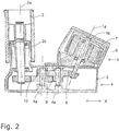
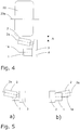
- Fig. 4 serves to clarify the so-called Störkanten problem.
- the axis of rotation 2a of the drive roller 2 is oblique to the axis of rotation 1a of the drive motor and also obliquely to the axis of rotation 20a of the wheel 20th
- Fig. 5 shows in a schematic front view ( Fig. 5a ) and rear view ( Fig. 5b ) A variant of the Rangierantriebs with inclined drive roller.
- the axis of rotation 2a of the drive roller 2 with a vertical component, here upwards, obliquely, while the axis of rotation 1a of the drive motor 1 is completely in a horizontal plane.
- the axis of rotation 1 a of the drive motor 1 is inclined with a vertical component up or down, while the drive roller 2 is completely in the horizontal.
- the horizontal components of the extensions of the axes of rotation 1 a, 2 a are at an oblique angle to each other.
Description
Die Erfindung betrifft einen Rangierantrieb für einen Anhänger, insbesondere für Wohnwagen, Bootsanhänger, Pferdeanhänger, Marktanhänger, Lastanhänger u. ä., nach dem Oberbegriff des Anspruchs 1.The invention relates to a shunting drive for a trailer, especially for caravans, boat trailers, horse trailers, market trailers, load trailers and. Ä., According to the preamble of
Anhänger werden üblicherweise von Zugmaschinen gezogen. So ist es bekannt, dass ein Pkw einen Wohnwagen ziehen kann. Wenn der Anhänger von der Zugmaschine abgenommen ist, wird er meist von Hand in die endgültige Position geschoben. Jedoch werden heutzutage zunehmend Anhänger im Wohnwagenbereich angeboten, die aufgrund ihrer Größe und damit ihres Gewichts nur noch unter Mühe von Hand verschoben werden können. Daher wurden Rangier- bzw. Hilfsantriebe entwickelt, die es ermöglichen. einen Anhänger auch ohne Zugmaschine mit Motorunterstützung zu verschieben bzw. zu drehen.Trailers are usually towed by tractors. So it is known that a car can pull a caravan. When the trailer is removed from the tractor, it is usually pushed by hand into the final position. However, nowadays trailers are increasingly offered in the caravan area, which can be moved only with difficulty by hand due to their size and thus their weight. Therefore, shunting or auxiliary drives have been developed that make it possible. to move or turn a trailer even without tractor with engine assistance.
In der
Aus der
In der
Der Erfindung liegt die Aufgabe zugrunde, einen Rangiertrieb für einen Anhänger anzugeben, der ein verbessertes Antriebskonzept aufweist, das zudem möglichst kompakt realisiert werden kann.The invention has for its object to provide a maneuver for a trailer, which has an improved drive concept, which also can be realized as compact as possible.
Die Aufgabe wird durch einen Rangierantrieb für einen Anhänger mit den Merkmalen von Anspruch 1 gelöst. Vorteilhafte Ausgestaltungen sind in den abhängigen Ansprüchen angegeben.The object is achieved by a shunting drive for a trailer with the features of
Ein Rangierantrieb für einen Anhänger, mit einer Befestigungseinrichtung zum Befestigen an dem Anhänger, einem relativ zu der Befestigungseinrichtung bewegbaren Träger, einem von dem Träger gehaltenen Antriebsmotor, und mit einer von dem Antriebsmotor drehend antreibbaren Antriebsrolle, ist dadurch gekennzeichnet, dass die Drehachse des Antriebsmotors schräg zur Drehachse der Antriebsrolle verläuft, also in einem schrägen Winkel zu der Drehachse der Antriebsrolle steht.A maneuvering drive for a trailer, comprising a fastening device for fastening to the trailer, a carrier movable relative to the fastening device, a drive motor held by the carrier, and a drive roller rotatably drivable by the drive motor, is characterized in that the axis of rotation of the drive motor is inclined extends to the axis of rotation of the drive roller, that is at an oblique angle to the axis of rotation of the drive roller.
Bei einer Variante ist eine Bewegungseinrichtung vorgesehen, zum Bewegen des Trägers zwischen einer Ruheposition, in der die Antriebsrolle von einem Rad des Anhängers getrennt ist, und einer Antriebsposition, in der die Antriebsrolle gegen das Rad des Anhängers gedrückt wird.In one variant, a movement device is provided for moving the carrier between a rest position in which the drive roller is separated from a wheel of the trailer, and a drive position in which the drive roller is pressed against the wheel of the trailer.
Der Rangierantrieb weist typischerweise den relativ zu der Befestigungseinrichtung bewegbaren Träger auf, der den Antriebsmotor und die Antriebsrolle trägt bzw. lagert. Mit Hilfe der Bewegungseinrichtung kann der Träger zwischen der Ruheposition und der Antriebsposition hin - und her bewegt werden, sodass die Antriebsrolle bei Bedarf gegen das Rad des Anhängers, insbesondere gegen die Lauffläche des Anhängerrads angedrückt oder von dem Rad abgehoben wird. Dieser Aufbau ist zum Beispiel aus der
Es hat sich herausgestellt, dass der Bauraum durch das zueinander Schrägstellen von Antriebsmotor und Antriebsrolle optimal ausgenutzt werden kann. Gerade bei modernen Wohnwagenanhängern ist der zur Verfügung stehende Bauraum unterhalb des Chassis oder im Radkasten begrenzt. Ein Grund dafür ist es, dass zu große Radkästen oder Freiräume im unteren Bereich des Anhängers die äußere Anmutung beeinträchtigen können. Zudem vermindern größere Ausschnitte im Bereich der Anhängerräder die Aerodynamik und können so zu einem erhöhten Kraftstoffverbrauch führen.It has been found that the space can be optimally utilized by the mutually inclined positioning of the drive motor and drive roller. Especially with modern trailers the available space is limited below the chassis or in the wheel arch. One reason for this is that too large wheel arches or clearances in the lower part of the trailer can affect the external appearance. In addition, larger cutouts in the area of the trailer wheels reduce the aerodynamics and can thus lead to increased fuel consumption.
Dementsprechend besteht das Bedürfnis, Rangierantriebe für Anhänger möglichst kompakt zu bauen. Durch das Schrägstellen der Drehachsen von Antriebsmotor und Antriebsrolle ergibt sich die Möglichkeit, den zur Verfügung stehenden Bauraum optimal auszunutzen. Zudem hat sich herausgestellt, dass durch ein leichtes Anstellen des Winkels die Geräuschentwicklung eines zur Kraftübertragung genutzten Getriebes vermindert werden kann, sodass der erfindungsgemäße Rangierantrieb geräuscharm ist.Accordingly, there is a need to build shunting drives for trailers as compact as possible. By tilting the axes of rotation of drive motor and drive roller, there is the possibility to make optimal use of the available space. It also turned out that by a slight adjustment of the angle, the noise of a transmission used for power transmission can be reduced, so that the Rangierantrieb invention is quiet.
Die Schrägstellung der Drehachsen kann bedeuten, dass die Drehachsen in einer gemeinsamen Horizontalebene liegen, jedoch zueinander schräg stehen. Ebenso ist es möglich, dass sich eine oder beide Drehachsen auch mit einer Vertikalkomponente erstrecken, so dass die Drehachsen windschief zueinander stehen, also eine Art räumliche Schrägstellung erreicht wird. Z. B. kann eine der Drehachsen ausschließlich in einer Horizontalebene liegen, während die andere Drehachse sich sowohl in Horizontal- als auch in Vertikalrichtung erstreckt.The inclination of the axes of rotation may mean that the axes of rotation lie in a common horizontal plane, but are inclined to each other. It is also possible that one or both axes of rotation also extend with a vertical component, so that the axes of rotation are skewed to each other, so a kind of spatial skew is achieved. For example, one of the axes of rotation may lie exclusively in a horizontal plane, while the other axis of rotation extends in both horizontal and vertical directions.
Die Schrägstellung der Drehachsen wird derart erreicht, dass der Winkel zwischen der Antriebsmotor- Drehachse (der Drehachse des Antriebsmotors) und der Antriebsrollen- Drehachse (der Drehachse der Antriebsrolle) größer als 0° ist, sodass die Drehachsen nicht parallel zueinander stehen. Gerade die parallele Anordnung der Drehachsen beim Stand der Technik führt zu einem relativ breiten, wuchtigen Rangierantrieb mit einem erhöhten Bauraumerfordernis.The inclination of the rotary axes is achieved such that the angle between the drive motor rotation axis (the rotation axis of the drive motor) and the drive roller rotation axis (the rotation axis of the drive roller) is greater than 0 °, so that the axes of rotation are not parallel to each other. Especially the parallel arrangement of the axes of rotation in the prior art leads to a relatively wide, massive Rangierantrieb with an increased space requirement.
Die Schrägstellung der Drehachsen wird zudem dadurch erreicht, dass der Winkel zwischen der Antriebsmotor-Drehachse und der Antriebsrollen-Drehachse ungleich 90° ist, sodass die Drehachsen nicht senkrecht zueinander stehen. Bei der senkrechten Anordnung der Drehachsen im Stand der Technik ist der Rangierantrieb zwar verhältnismäßig schlank gestaltet. Jedoch erfordert der schlanke Aufbau eine langgestreckte Ausführung, die entsprechenden Bauraum erfordert.The inclination of the axes of rotation is also achieved in that the angle between the drive motor axis of rotation and the drive roller axis of rotation is not equal to 90 °, so that the axes of rotation are not perpendicular to each other. In the vertical arrangement of the axes of rotation in the prior art, the Rangierantrieb is indeed designed relatively slim. However, the slender construction requires an elongated design that requires appropriate space.
Somit bedeutet eine "schräge" Anordnung der Achsen, dass die Achsen nicht im Winkel von 0° oder von 90° zueinander stehen. Z. B. kann der Winkel in einem Bereich zwischen 1° und 89°, bevorzugt zwischen 2° und 88° liegen.Thus, an "oblique" arrangement of the axes means that the axes are not at an angle of 0 ° or 90 ° to each other. For example, the angle may be in a range between 1 ° and 89 °, preferably between 2 ° and 88 °.
Bereits eine Schrägstellung von wenigen Grad kann dazu führen, dass ein zur Kraftübertragung zwischen dem Antriebsmotor und der Antriebsrolle vorgesehenes Getriebe eine deutlich geringere Geräuschentwicklung zeigt. Hierbei hat sich eine Winkelstellung zwischen 1 und 10° insbesondere zwischen 3 und 10° als geeignet erwiesen.Already an inclination of a few degrees can lead to a provided for power transmission between the drive motor and the drive roller transmission shows a significantly lower noise. Here, an angular position between 1 and 10 °, in particular between 3 and 10 ° has been found to be suitable.
Auch andere Winkelbereiche für die Schrägstellung der Drehachsen können vorteilhaft sein. Eine Winkelstellung zwischen 10° und 80° bzw. - je nach Bezugnahme der Winkelmessung zwischen 100° und 170°, aber auch bis knapp unter 180° können zweckmäßig sein.Other angular ranges for the inclination of the axes of rotation may be advantageous. An angular position between 10 ° and 80 ° or - depending on Reference the angle measurement between 100 ° and 170 °, but also to just below 180 ° may be appropriate.
Die Winkelstellung erfordert eine geeignete Auswahl und Gestaltung der notwendigen Getriebeeinrichtung, wie später noch erläutert wird.The angular position requires a suitable selection and design of the necessary transmission device, as will be explained later.
Die Schrägstellung sollte insbesondere in der Ruheposition, also im entlasteten Zustand bestehen.The inclination should exist especially in the rest position, ie in the unloaded state.
Die Antriebsrolle kann an dem Träger einseitig gelagert sein.The drive roller may be mounted on one side of the carrier.
Im Kraftfluss zwischen dem Antriebsmotor und der Antriebsrolle kann eine Getriebeeinrichtung vorgesehen sein. Mit Hilfe der Getriebeeinrichtung wird die Antriebsleistung des Antriebsmotors auf die Antriebsrolle übertragen. Dabei kann insbesondere die üblicherweise hohe Motordrehzahl untersetzt werden, um sie in eine geeignete Drehzahl für die Antriebsrolle zu wandeln. Gleichzeitig wird das Antriebsdrehmoment des Motors erhöht, sodass die Antriebsrolle das ihr zugeordnete Anhängerrad kraftvoll bewegen kann.In the power flow between the drive motor and the drive roller, a transmission device may be provided. With the help of the transmission device, the drive power of the drive motor is transmitted to the drive roller. In particular, the usually high engine speed can be reduced in order to convert it into a suitable speed for the drive roller. At the same time, the drive torque of the motor is increased so that the drive roller can powerfully move its associated trailer wheel.
Die Getriebeeinrichtung kann von dem Träger gehalten sein. Bei einer Ausführungsform kann der Träger zum Beispiel gleichzeitig einen Teil des Getriebegehäuses bilden, sodass der Träger und das Getriebegehäuse in einer Baugruppe integriert sind.The transmission device may be held by the carrier. For example, in one embodiment, the carrier may simultaneously form part of the transmission housing, such that the carrier and the transmission housing are integrated into an assembly.
Die Getriebeeinrichtung kann wenigstens eine Komponente aufweisen, ausgewählt aus der Gruppe Stirnradstufe, Kegelradstufe, Kronradstufe, Schneckenradstufe, Hypoidstufe, Doppelzahnrad, einstückig ausgeführtes Doppelzahnrad. Je nach Winkelstellung zwischen der Drehachse des Antriebsmotors und der Drehachse der Antriebsrolle kann somit ein geeignetes Getriebe aufgebaut werden, wobei auch verschiedene Komponenten miteinander kombinierbar sind.The transmission device may comprise at least one component selected from the group of spur gear, bevel gear, crown wheel, worm wheel, hypoid, double gear, integral double gear. Depending on the angular position between the axis of rotation of the drive motor and the axis of rotation of the drive roller thus a suitable transmission can be constructed, with different components can be combined.
Bei den Zahnrädern kann eine Geradeverzahnung oder eine Schrägverzahnung verwendet werden.In the gears, a straight toothing or a helical toothing can be used.
Das einstückig ausgeführte Doppelzahnrad, also zwei Zahnräder - meist mit unterschiedlicher Zähnezahl - auf einer gemeinsamen Drehachse - kann gerade bei höheren Stückzahlen einfach hergestellt werden. Bei geschickter Auslegung des Getriebes ist es möglich, mit mehreren Gleichkomponenten, also zum Beispiel mehreren, in geeigneter Weise gepaarten Doppelzahnrädern, sehr einfach das Getriebe aufzubauen.The integrally executed double gear, so two gears - usually with different numbers of teeth - on a common axis of rotation - can be easily produced especially at higher volumes. With clever design of the transmission, it is possible with several equal components, so for example several, suitably paired double gears, very easy to build the transmission.
Vor allem die Stirnrad - und Kegelradstufen können dabei vorteilhaft sein, weil sie den Aufbau von Getrieben mit hohem Wirkungsgrad ermöglichen. Demgegenüber weist zum Beispiel eine Schneckenradstufe einen deutlich geringeren Wirkungsgrad auf, der unter Umständen derart niedrig sein kann, dass das Getriebe selbsthemmend ist. Dies wiederum hat den Vorteil, dass keine zusätzliche Bremseinrichtung vorgesehen sein muss, um den Rangierantrieb zum Bremsen und Halten des ihm zugeordneten Anhängerrads zu nutzen.Especially the spur and bevel gear stages can be advantageous because they allow the construction of gears with high efficiency. In contrast, for example, a worm wheel has a much lower efficiency, which may be so low under certain circumstances that the transmission is self-locking. This in turn has the advantage that no additional braking device must be provided in order to use the Rangierantrieb for braking and holding the associated trailer wheel.
Alternativ zu einem Zahnradgetriebe können auch andere Getriebearten verwendet werden, beispielsweise ein Riemengetriebe.As an alternative to a gear transmission, other types of transmission may be used, such as a belt transmission.
Bei einer Variante weist der Antriebsmotor eine Antriebswelle auf, die sich entlang der Antriebsmotor-Drehachse erstreckt. Dementsprechend weist die Antriebsrolle eine Rollenwelle auf, die sich entlang der Antriebsrollen- Drehachse erstreckt. Die Getriebeeinrichtung kann wenigstens eine Zwischenstufe mit einer Getriebewelle aufweisen, wobei die Getriebewelle parallel zu der Antriebswelle oder parallel zu der Rollenwelle angeordnet ist. Dabei kann die Getriebewelle zwischen der Antriebswelle und der Rollenwelle angeordnet sein. Das bedeutet, dass - wenn man eine Hauptorientierung des Rangierantriebs zugrunde legt, die durch die Anordnung der meisten Komponenten bestimmt wird und z.B. einer Bewegungsachse des Trägers bei seiner Bewegung zwischen Ruhe- und Antriebsposition entspricht - entweder die Antriebsrolle oder der Antriebsmotor schräg zu dem restlichen Rangierantrieb angeordnet sein kann. Je nach zur Verfügung stehendem Bauraum können diejenigen Komponenten bezüglich der Hauptrichtung des Rangierantriebs schräggestellt werden, die sich aus technischen oder gestalterischen Gründen dafür eignen. Als Hauptrichtung des Rangierantriebs kann auch diejenige Richtung verstanden werden, die der Längsrichtung des Anhängers entspricht, an dem der Rangierantrieb befestigt werden soll.In a variant, the drive motor has a drive shaft which extends along the drive motor rotation axis. Accordingly, the drive roller has a roller shaft extending along the drive roller rotation axis. The transmission device may have at least one intermediate stage with a transmission shaft, wherein the transmission shaft is arranged parallel to the drive shaft or parallel to the roller shaft. In this case, the transmission shaft can be arranged between the drive shaft and the roller shaft. This means that, given a main orientation of the shunting drive, which is determined by the arrangement of most components and e.g. a movement axis of the carrier during its movement between rest and drive position corresponds - either the drive roller or the drive motor can be arranged obliquely to the remaining Rangierantrieb. Depending on the available space, those components can be tilted with respect to the main direction of the Rangierantriebs, which are suitable for technical or design reasons. The main direction of the Rangierantriebs can also be understood that direction which corresponds to the longitudinal direction of the trailer to which the Rangierantrieb is to be attached.
Bei einer Variante kann der Träger durch die Bewegungseinrichtung auf einer Bewegungsachse zwischen der Ruheposition und der Antriebsposition hin- und herbewegbar sein. Dabei kann entweder bei einer ersten Variante die Antriebsrollen-Drehachse senkrecht zu der Bewegungsachse und die Antriebsmotor -Drehachse schräg zu der Bewegungsachse stehen oder bei einer zweiten Variante die Antriebsrollen-Drehachse schräg zu der Bewegungsachse und die AntriebsmotorDrehachse senkrecht oder parallel zu der Bewegungsachse stehen.In a variant, the carrier can be reciprocated by the movement device on a movement axis between the rest position and the drive position. In this case, either in a first variant, the drive roller rotation axis perpendicular to the movement axis and the drive motor rotation axis are inclined to the movement axis or at a second variant, the drive roller rotation axis obliquely to the movement axis and the drive motor rotation axis are perpendicular or parallel to the movement axis.
Als Bewegungsachse wird somit die Bewegungsrichtung des Trägers verstanden, die er vollzieht. wenn er von der Bewegungseinrichtung hin - bzw. herbewegt wird.As a movement axis is thus understood the direction of movement of the wearer, he performs. when moved by the moving device.
Bei einer dritten Variante können beide Drehachsen, sowohl die Antriebsrollen-Drehachse als auch die Antriebsmotor-Drehachse, schräg zu der Bewegungsachse stehen.In a third variant, both axes of rotation, both the drive roller rotation axis and the drive motor rotation axis, are inclined to the movement axis.
Die Bewegungsachse kann zudem eine Achse sein, zu der wenigstens eine Drehachse einer Komponente der Getriebeeinrichtung senkrecht steht. Auf diese Weise können zum Beispiel sowohl der Antriebsmotor als auch die Antriebsrolle schräg zu der Getriebeeinheit bzw. Komponenten der Getriebeeinheit ausgerichtet sein.The movement axis may also be an axis to which at least one axis of rotation of a component of the transmission device is perpendicular. In this way, for example, both the drive motor and the drive roller can be aligned obliquely to the gear unit or components of the gear unit.
Die beiden Drehachsen sowie die Bewegungsachse können jeweils in einer Horizontalebene liegen. Ebenso ist es aber auch möglich, dass sich wenigstens eine der Drehachsen und/oder die Bewegungsachse aus der Horizontalebene heraus, also auch mit einer Vertikalkomponente erstrecken. In diesem Fall verläuft die betreffende Achse in einem schrägen Winkel zur Horizontalebene, so dass eine räumliche Schrägstellung erreicht wird.The two axes of rotation and the axis of motion can each lie in a horizontal plane. However, it is also possible for at least one of the axes of rotation and / or the movement axis to extend out of the horizontal plane, ie also with a vertical component. In this case, the relevant axis runs at an oblique angle to the horizontal plane, so that a spatial inclination is achieved.
Bei einer Variante steht die Antriebsrollen-Drehachse nur minimal schräg zu den restlichen Komponenten, insbesondere nur minimal schräg zu der Bewegungsachse des Trägers. Der Winkel der Antriebsrollen-Drehachse kann in diesem Fall z. B. nur wenige Grad, z.B. 1 bis 4° von einer senkrechten Anordnung zwischen der Antriebsrollen- Drehachse und der Bewegungsachse abweichen.In one variant, the drive roller rotation axis is only minimally oblique to the remaining components, in particular only minimally oblique to the axis of movement of the carrier. The angle of the drive roller rotation axis can in this case z. B. only a few degrees, e.g. 1 to 4 ° deviate from a vertical arrangement between the drive roller rotation axis and the movement axis.
Der Antriebsmotor kann zum Beispiel ein Universalmotor oder ein bürstenloser Elektromotor sein. Insbesondere ein bürstenloser Elektromotor mit Außenläufer (Außenläufermotor) kann zweckmäßig sein, weil er einen besonders kompakten Aufbau ermöglicht. Insbesondere die axiale Länge eines derartigen Außenläufermotors ist gering und erhöht somit die Kompaktheit.The drive motor may be, for example, a universal motor or a brushless electric motor. In particular, a brushless electric motor with external rotor (external rotor motor) may be appropriate because it allows a particularly compact design. In particular, the axial length of such an external rotor motor is low and thus increases the compactness.
Ein Außenläufermotor hat zudem den Vorteil, dass er ein höheres Drehmoment erzeugt als ein Innenläufermotor. Zudem kann aufgrund des erhöhten Drehmoments die Drehzahl des Motors reduziert werden, was sich vorteilhaft für die Auslegung der zwischen dem Antriebsmotor und der Antriebsrolle erforderlichen Getriebeeinrichtung, insbesondere für die Anforderung an die Übersetzungsverhältnisse auswirkt. Durch die Bauform eines Außenläufermotors können darüber hinaus das Bauvolumen und Gewicht spürbar reduziert werden.An external rotor motor also has the advantage that it generates a higher torque than an internal rotor motor. In addition, due to the increased Torque, the speed of the motor can be reduced, which is advantageous for the interpretation of the required between the drive motor and the drive roller gear device, in particular for the requirement of the gear ratios. Due to the design of an external rotor motor, the construction volume and weight can be noticeably reduced.
Es kann eine Bremseinrichtung vorgesehen sein, die ein Bremsen der Antriebsrolle bewirkt. Die Bremseinrichtung kann insbesondere direkt auf den Antriebsmotor, dessen Antriebswelle (Motorwelle) oder zum Beispiel auf den Außenläufer wirken und durch ein Bremsen der Antriebswelle oder des Außenläufers ein Abbremsen der Antriebsrolle bewirken.It may be provided a braking device which causes braking of the drive roller. The braking device can, in particular, act directly on the drive motor, its drive shaft (motor shaft) or, for example, on the external rotor and cause the drive roller to decelerate by braking the drive shaft or the external rotor.
Zu diesem Zweck kann die Bremseinrichtung stirnseitig zu dem Antriebsmotor angeordnet sein. Ergänzend oder alternativ kann die Bremseinrichtung an dem Außenläufer befestigt sein, um auf diese Weise ein Drehen des Motors bzw. des Außenläufers zu verhindern, was folglich auch zu einem Blockieren der Antriebsrolle führt.For this purpose, the braking device can be arranged frontally to the drive motor. Additionally or alternatively, the braking device may be attached to the external rotor so as to prevent rotation of the motor or the external rotor, which consequently also leads to a blockage of the drive roller.
Ebenso ist es möglich. dass die Bremseinrichtung an anderer Stelle wirkt, zum Beispiel in der Getriebeeinrichtung, um ein Bremsen bzw. Blockieren der Antriebsrolle zu erreichen.It is also possible. in that the braking device acts elsewhere, for example in the transmission device, in order to achieve a braking or blocking of the drive roller.
Vorzugsweise ist zwischen dem Motor und dem Getriebe eine Kupplung zur Schwingungsdämpfung vorgesehen. Diese enthält üblicherweise eine dämpfendes Gummielement zwischen der Antriebs- und der Abtriebsseite, wodurch eventuelle Unwuchten oder Fluchtungsfehler ausgeglichen und Geräusche vermieden werden können. Die Kupplung kann auch als Balgkupplung ausgebildet sein.Preferably, a coupling for vibration damping is provided between the engine and the transmission. This usually includes a damping rubber element between the input and the output side, which can be compensated for any imbalances or misalignments and noise can be avoided. The coupling can also be designed as a bellows coupling.
Die Antriebsrolle kann über ihre axiale Erstreckung eine veränderliche Außenkontur aufweisen, derart, dass der Durchmesser der Antriebsrolle im Bereich ihrer axialen Mitte größer ist als an ihren axialen Rändern. Wenn die Antriebsrolle somit in der Mitte einen etwas größeren Durchmesser aufweist als an den Rändern, also z.B. eine bombierte Form aufweist, kann sie auf der Lauffläche des Anhängerrads etwas tiefer eindringen als an den Rändern. Da jedoch die Lauffläche des Anhängerrads prinzipbedingt weicher ist als die eher steiferen Flanken des Anhängerrads, kann auf diese Weise eine insgesamt gleichmäßige Anpressdruckverteilung zwischen Antriebsrolle und Anhängerrad erreicht werden.The drive roller may have over its axial extent a variable outer contour, such that the diameter of the drive roller is greater in the region of its axial center than at its axial edges. If the drive roller thus has a slightly larger diameter in the middle than at the edges, ie, for example, has a convex shape, it can penetrate slightly deeper on the running surface of the trailer than at the edges. However, since the tread of the trailer is inherently softer than the rather stiffer flanks of the trailer, a total uniform contact pressure distribution between the drive roller and trailer can be achieved in this way.
Bei einer Ausführungsform kann die Antriebsrollen-Drehachse schräg zu der Drehachse des Rads des Anhängers stehen, wobei wenigstens ein Teil der Antriebsrolle in dem dem Rad des Anhängers zugewandten Bereich vor anderen Komponenten, insbesondere vor dem Träger oder dem Getriebegehäuse, in Richtung des Rads übersteht, derart, dass bei einem Bewegen des Trägers mit der Antriebsrolle aus der Ruheposition in die Antriebsposition zuerst der betreffende Teil der Antriebsrolle in Kontakt mit dem Rad des Anhängers gelangt, nämlich bevor die betreffende andere Komponente in Kontakt mit dem Rad gelangen kann.In one embodiment, the drive roller rotation axis may be oblique to the axis of rotation of the trailer wheel, with at least a portion of the drive roller protruding toward the wheel in the region facing the wheel of the trailer in front of other components, particularly in front of the carrier or transmission housing, such that upon movement of the carrier with the drive roller from the rest position to the drive position, the relevant part of the drive roller first comes in contact with the wheel of the trailer, namely before the other component concerned can come into contact with the wheel.
Mit dieser Lösung kann insbesondere der sogenannten Störkanten-Problematik entgegen gewirkt werden. Wenn die betreffende Komponente, also insbesondere ein Teil des Trägers oder des Getriebegehäuses nach vorne in Richtung des Anhängerrads übersteht, besteht je nach Dimensionierung des Anhängerrads und der Anordnung des Rangierantriebs die Gefahr. dass die Komponente an dem Anhängerrad reibt oder schleift. Mit der Schrägstellung der Antriebsrollen-Drehachse wird erreicht, dass wenigsten ein Teil der Antriebsrolle nach vorne, in Richtung des Anhängerrads übersteht, und zwar noch über die anderen Komponenten hinaus. Dadurch gelangt dieser Teil der Antriebsrolle zuerst in Kontakt mit dem Anhängerrad. Da die Antriebsrolle in dieser Situation bereits ihre Antriebsposition erreicht hat, kann der Träger nicht mehr weiter in Richtung des Anhängerrads bewegt werden, so dass auch keine weiteren Komponenten mehr gegen das Anhängerrad gedrückt werden können.With this solution, in particular the so-called Störkanten problem can be counteracted. If the component in question, ie in particular a part of the carrier or the gear housing protrudes forward in the direction of the trailer, depending on the dimensions of the trailer and the arrangement of Rangierantriebs the risk. that the component rubs or grinds on the trailer wheel. With the inclination of the drive roller rotation axis is achieved that at least a part of the drive roller protrudes forward, in the direction of the trailer wheel, even beyond the other components. As a result, this part of the drive roller first comes into contact with the trailer wheel. Since the drive roller has already reached its drive position in this situation, the carrier can not be moved further in the direction of the trailer wheel, so that no further components can be pressed against the trailer.
Diese und weitere Vorteile und Merkmale der Erfindung werden nachfolgend anhand von Beispielen unter Zuhilfenahme der begleitenden Figuren näher erläutert. Es zeigen:
-
Figur 1 -
Figur 2 -
Figur 3 -
Figur 4 -
Figur 5
-
FIG. 1 an external perspective view of a Rangierantriebs; -
FIG. 2 schematic representation of a Rangierantrieb with inclined drive motor; -
FIG. 3 in a schematic sectional view of a Rangierantrieb with inclined drive roller; -
FIG. 4 a representation of the Störkanten problem; and -
FIG. 5 another embodiment of a Rangierantriebs with inclined drive roller.
Der Antriebsmotor 1 und die Antriebsrolle 2 sind von einem Träger 3 gehalten. Im Inneren des Trägers 3 ist auch eine Getriebeeinrichtung 4 angeordnet, die dazu dient, die verhältnismäßig hohe Drehzahl des Antriebsmotors 1 in eine niedrigere Drehzahl für die Antriebsrolle 2 zu übersetzen. Die Getriebeeinrichtung 4 ist in
Der Träger 3 wird von einer Befestigungseinrichtung 5 gehalten, die ihrerseits an einem nicht dargestellten Fahrgestell eines Anhängers angebracht werden kann. Zum Beispiel kann die Befestigungseinrichtung 5 in Form eines Vierkantrohrs ausgeführt sein, das auf ein entsprechendes Querrohr (nicht dargestellt) aufgeschoben werden kann, wobei das Querrohr wiederum an der Unterseite des Anhängers befestigt ist.The
Insbesondere kann die Befestigungseinrichtung 5 auch eine Halterung 5a aufweisen, die den Träger 3 trägt. Der Träger 3 ist dann relativ zu der Halterung 5a hin und her bewegbar. So kann es zweckmäßig sein, wenn die Halterung 5a eine geeignete Linearführung aufweist, um ein lineares Bewegen des Trägers 3 zu ermöglichen.In particular, the
Der Träger 3 ist relativ zu der Befestigungseinrichtung 5 mit Hilfe einer nicht dargestellten Bewegungseinrichtung linear hin und her bewegbar. Auf diese Weise kann der Träger 3 zwischen einer Ruheposition, in der die Antriebsrolle 2 von einem Rad 6 des Anhängers getrennt ist, und einer Antriebsposition, in der die Antriebsrolle 2 gegen das Rad 6 des Anhängers gedrückt wird - wie in
Der Träger 3 ist zusammen mit dem Antriebsmotor 1 und der Antriebsrolle 2 sowie der Getriebeeinr1chtung 4 entlang der Bewegungsachse X in einer geraden oder gekrümmten Bahn hin - und her bewegbar, um zwischen der Ruheposition und der Antriebsposition verschoben werden zu können.The
Erfindungsgemäß verlaufen die Drehachse 1a des Antriebsmotors 1 und die Drehachse 2a der Antriebsrolle 2 in einem schrägen Winkel zueinander, was später noch anhand weiterer Figuren erläutert wird.According to the invention, the axis of
Anders als bei der
Darüber hinaus kann eine geringfügige Winkelstellung den Ausgleich von Toleranzen in den Lagern und Führungen im Lastzustand ermöglichen. Derartige Toleranzen ergeben sich insbesondere in der einseitigen Lagerung der Antriebsrolle 2 sowie in der Linearführung des Trägers 3 in der Halterung 5a. Wenn die Antriebsrolle 2 beim Andrücken gegen die Lauffläche des Anhängerrads belastet wird, wird sie aufgrund der einseitigen Lagerung zwangsläufig etwas ausweichen und dadurch ihre Winkelstellung verändern. Dadurch besteht die Gefahr, dass die Kraftübertragung zwischen der Antriebsrolle 2 und dem Anhängerrad nicht mehr optimal ist. Wenn hingegen durch die entsprechende Schrägstellung der Drehachse 2a der Antriebsrolle 2 diese Ausgleichbewegung vorweggenommen ist, kann auch im Lastzustand (Antriebsposition des Trägers 3) sichergestellt werden, dass die Drehachse 2a der Antriebsrolle 2 parallel zu der Drehachse des nicht dargestellten Anhängerrads steht. Diese Stellung ist für eine gleichmäßige Kraftübertragung und damit gute Traktion optimal.In addition, a slight angular position allow the compensation of tolerances in the bearings and guides in the load condition. Such tolerances arise in particular in the one-sided mounting of the
Der Winkelausgleich der Antriebsrollen-Drehachse kann auch dadurch unterstützt werden, dass die Antriebsrolle 2 eine geringfügig bombierte Form aufweist. Insbesondere kann die Antriebsrolle 2 im Bereich ihrer axialen Mitte 2b einen größeren Durchmesser aufweisen als an ihren axialen Rändern bzw. Enden. Durch diese bombierte Form der Antriebsrolle 2 wird erreicht, dass der Druck in der Mitte der Lauffläche des Anhängerrads 2 etwas größer ist als an den steiferen Flanken des Rads. Dies führt zu einer Vergleichmäßigung des Anpressdrucks der Antriebsrolle 2 am Anhängerrad, so dass insgesamt das Drehmoment zuverlässiger übertragen werden kann.The angle compensation of the drive roller rotation axis can also be supported by the fact that the
Die Schrägstellung der Drehachsen 1 a, 2a von Antriebsmotor 1 und Antriebsrolle 2 ist bei dem Rangierantrieb von
Die Winkelstellung zwischen Antriebsmotor und Antriebswelle kann aber - je nach Ausgestaltung - auch größer sein und dementsprechend auch größere Winkel einnehmen. Lediglich die Winkelstellung 90°, wie sie zum Beispiel aus der
Hier ist deutlich erkennbar, dass eine Drehachse 1a des Antriebsmotors 1 in einem schrägen Winkel zu einer Drehachse 2a der Antriebsrolle 2 steht. Der Winkel in dem gezeigten Beispiel beträgt etwa 40 bis 45°. Wie oben gesagt, kann er aber auch deutlich größer oder kleiner sein.Here it can be clearly seen that a
Der Antriebsmotor 1 ist als bürstenloser Außenläufermotor ausgebildet, mit einem Innenstator 6 und einem Außenläufer 7. Der Außenläufer 7 ist mit einer Antriebswelle 1 b des Antriebsmotors 1 gekoppelt.The
Sowohl der Antriebsmotor 1 als auch die Antriebsrolle 2 sind an dem Träger 3 gelagert bzw. gehalten.Both the
Im Inneren des Trägers 3 ist die Getriebeeinrichtung 4 untergebracht. Dementsprechend dient der Träger 3 gleichermaßen als Getriebegehäuse für die Getriebeeinrichtung 4.Inside the
In dem in
Die Achsen 4a der Getriebeeinrichtung 4 stehen parallel zu der Drehachse 2a der Antriebsrolle 2 und damit im schrägen Winkel zu der Drehachse 1a des Antriebsmotors 1.The
Dementsprechend ist die erste Getriebestufe 8 derart auszugestalten, dass eine Kraftübertragung über einen schrägen Winkel möglich ist. Dazu eignet sich zum Beispiel eine in
Als weitere Getriebestufen (zweite Getriebestufe 9, dritte Getriebestufe 10) können Stirnradstufen eingesetzt werden.As further gear stages (
In der Getriebeeinrichtung 4 können auch Doppelzahnräder (zum Beispiel für die zweite Getriebestufe 9 und die dritte Getriebestufe 1 0) genutzt werden, also Zahnräder, bei denen zwei Zahnräder auf einer gemeinsamen Achse angeordnet sind. Zur Fertigungsvereinfachung können die Doppelzahnräder einstückig bzw. einteilig ausgeführt werden.In the
Die Getriebeeinrichtung treibt schließlich eine Antriebswelle der Antriebsrolle 2 (Rollenwelle 2c) an.The transmission device finally drives a drive shaft of the drive roller 2 (
An dem Antriebsmotor 1, insbesondere an dem Außenläufer 7 des Antriebsmotors 1 kann eine nicht dargestellte Bremseinrichtung vorgesehen sein, um den Antriebsmotor 1 und damit auch die Antriebsrolle 2 zu bremsen oder zu blockieren.On the
Bei der Variante von
Die Schrägstellung der Drehachse 2a der Antriebsrolle 2 kann nur sehr geringfügig von einer Parallelanordnung der Drehachse 2a der Antriebsrolle 2 zu der Drehachse 1a des Antriebsmotors 1 abweichen, wie oben bereits dargelegt. So kann der Schrägstellungswinkel z.B. nur in einem Bereich von 1 bis 3° liegen.The inclination of the axis of
Bei einem derart geringen Schrägstellungswinkel ist es nicht unbedingt erforderlich, in der Getriebeeinrichtung 4 ein entsprechendes Winkelgetriebe, z. B. ein Kegelradgetriebe vorzusehen. Vielmehr sind Stirnradgetriebe bekannt, die eine Schrägstellung der Drehachsen mit geringem Winkel tolerieren, so dass jedenfalls die Funktionsfähigkeit der Getriebeeinrichtung 4 über die Lebensdauer des Rangierantriebs gewährleistet ist.With such a small skew angle, it is not absolutely necessary in the
Die Getriebeeinrichtung 4 von
Der verhältnismäßig kleine Winkel der beiden Drehachsen 1 a und 2a zueinander führt dazu, dass die Drehachsen 1 a, 2a nicht ganz parallel zueinander stehen. Dadurch ist der Wirkungsgrad der Getriebeeinrichtung geringfügig schlechter, was aber u.a. durch die Vorteile hinsichtlich der Geräuschentwicklung kompensiert wird.The relatively small angle of the two axes of
In der Draufsicht ist der Rangierantrieb von
Durch die Schrägstellung der Drehachse 2a der Antriebsrolle 2 ist es möglich, dass wenigstens ein Teil der Antriebsrolle 2 nach vorne, in Richtung des Rads 20 im Verhältnis zu dem Träger 3 bzw. der Getriebeeinrichtung 4 übersteht. Der Überstand ist in
Beim Anstellen der Antriebsrolle 2 an die Lauffläche des Rads 20 wird s o die Gefahr vermindert, dass das Rad 20 an dem Träger 3 bzw. dem Getriebegehäuse der Getriebeeinrichtung 4 entlang schleifen kann.When attaching the
In diesem Fall ist die Drehachse 2a der Antriebsrolle 2 mit einer vertikalen Komponente, hier nach oben, schräg gestellt, während die Drehachse 1a des Antriebsmotors 1 vollständig in einer Horizontalebene liegt.In this case, the axis of
Selbstverständlich ist auch eine Variante möglich, bei der die Drehachse 1 a des Antriebsmotors 1 mit einer Vertikalkomponente nach oben oder unten schräg steht, während die Antriebsrolle 2 vollständig in der Horizontalen liegt. Dabei können auch die Horizontalkomponenten der Erstreckungen der Drehachsen 1 a, 2a in einem schrägen Winkel zueinander stehen.Of course, a variant is possible in which the axis of
Schließlich sind auch Ausführungsformen denkbar, bei denen die Drehachsen 1 a und 2a windschief zueinander im Raum stehen. So kann es z. B. sein, dass sich wenigstens eine der Drehachsen 1 a, 2a sowohl mit einer Horizontalkomponente als auch mit einer Vertikalkomponente - bezogen auf eine Horizontalebene - erstreckt.Finally, embodiments are conceivable in which the axes of
Claims (14)
- A maneuvering drive for a trailer, comprising- a fastening means (5) for fastening to the trailer;- a carrier (3) which can be moved relative to the fastening means (5);- a drive motor held by the carrier (3); and comprising- a drive roller (2) adapted to be rotationally driven by the drive motor (1);
characterized in that- the axis of rotation (1 a) of the drive motor (1) extends obliquely to the axis of rotation (2a) of the drive roller (2), and in that the angle between the drive motor axis of rotation (1a) and the drive roller axis of rotation (2a) is greater than 0 degrees, so that the axes of rotation (1a, 2a) are not parallel to each other, and is not equal to 90 degrees, so that the axes of rotation (1a, 2a) are not perpendicular to each other. - The maneuvering drive according to any of the preceding claims, characterized in that a transmission means (4) is provided in the force flow between the drive motor (1) and the drive roller (2).
- The maneuvering drive according to claim 4, characterized in that a coupling for vibration damping and for the compensation of fit tolerances is provided between the transmission means (4) and the drive motor (1).
- The maneuvering drive according to either of claims 2 and 3, characterized in that the transmission means (4) is held by the carrier (3).
- The maneuvering drive according to any of claims 2 to 4, characterized in that the transmission means (4) includes at least one component selected from the group of spur gear section, bevel gear section, crown wheel section, worm gear section, hypoid section, double gear, integrally formed double gear, belt drive.
- The maneuvering drive according to any of claims 2 to 5, characterized in that- the drive motor (1) includes a drive shaft (1 b) which extends along the drive motor axis of rotation (1 a);- the drive roller (2) includes a roller shaft (2b) which extends along the drive roller axis of rotation (2a);- the transmission means (4) includes at least one intermediate section (8, 9, 10) with a transmission shaft (4a); and in that- the transmission shaft (4a) is arranged parallel to the drive shaft (1 b) or parallel to the roller shaft (2b).
- The maneuvering drive according to any of the preceding claims, characterized in that- a movement means is provided, for moving the carrier (3) between a rest position, in which the drive roller (2) is spaced apart from a wheel of the trailer, and a drive position, in which the drive roller (2) is pressed against the wheel of the trailer; and in that- the carrier (3) is adapted to be reciprocated between the rest position and the drive position on a movement axis (X) by the movement means.
- The maneuvering drive according to claim 7, characterized in that the drive roller axis of rotation (2a) is perpendicular to the movement axis (X) and the drive motor axis of rotation (1 a) is oblique to the movement axis (X).
- The maneuvering drive according to claim 7, characterized in that the drive roller axis of rotation (2a) is oblique to the movement axis (X) and the drive motor axis of rotation (1 a) is perpendicular or parallel to the movement axis (X).
- The maneuvering drive according to claim 7, characterized in that the drive roller axis of rotation (2a) and the drive motor axis of rotation (1a) are oblique to the movement axis (X).
- The maneuvering drive according to any of the preceding claims, characterized in that the drive motor (1) is a brushless electric motor with an external rotor.
- The maneuvering drive according to any of the preceding claims, characterized in that a braking means is provided.
- The maneuvering drive according to any of the preceding claims, characterized in that the drive roller (2) has an outer contour that is variable over its axial extent, such that the diameter of the drive roller (2) in the region of its axial center (2b) is larger than on its axial edges.
- The maneuvering drive according to any of the preceding claims, characterized in that- the drive roller axis of rotation (2a) is oblique to the axis of rotation (20a) of the wheel (20) of the trailer; and in that- at least part of the drive roller (2) in the region facing the wheel (20) of the trailer projects towards the wheel (20) in front of other components such that upon a movement of the carrier (3) with the drive roller (2) from the rest position to the drive position, first the part in question of the drive roller (2) will move into contact with the wheel (20) of the trailer.
Applications Claiming Priority (1)
| Application Number | Priority Date | Filing Date | Title |
|---|---|---|---|
| DE102012010547.9A DE102012010547B4 (en) | 2012-05-29 | 2012-05-29 | Shunting drive for a trailer |
Publications (3)
| Publication Number | Publication Date |
|---|---|
| EP2669155A2 EP2669155A2 (en) | 2013-12-04 |
| EP2669155A3 EP2669155A3 (en) | 2014-05-21 |
| EP2669155B1 true EP2669155B1 (en) | 2017-01-04 |
Family
ID=48444213
Family Applications (1)
| Application Number | Title | Priority Date | Filing Date |
|---|---|---|---|
| EP13168269.2A Active EP2669155B1 (en) | 2012-05-29 | 2013-05-17 | Trailer manoeuvring drive with a gear unit with non-parallel axle arrangement |
Country Status (3)
| Country | Link |
|---|---|
| EP (1) | EP2669155B1 (en) |
| DE (2) | DE202012006086U1 (en) |
| DK (1) | DK2669155T3 (en) |
Families Citing this family (5)
| Publication number | Priority date | Publication date | Assignee | Title |
|---|---|---|---|---|
| DE202015105911U1 (en) * | 2015-11-05 | 2016-01-12 | Truma Gerätetechnik GmbH & Co. KG | Shunting drive for a trailer |
| AU201712794S (en) | 2016-11-23 | 2017-05-23 | Dometic Sweden Ab | Ventilation and air conditioning apparatus |
| DE112018005883T5 (en) | 2017-11-16 | 2020-07-30 | Dometic Sweden Ab | AIR-CONDITIONING DEVICE FOR MOTORHOMES |
| USD905217S1 (en) | 2018-09-05 | 2020-12-15 | Dometic Sweden Ab | Air conditioning apparatus |
| DE102019205987B4 (en) * | 2019-04-26 | 2022-05-05 | Zf Friedrichshafen Ag | Electric axle drive for a vehicle |
Family Cites Families (7)
| Publication number | Priority date | Publication date | Assignee | Title |
|---|---|---|---|---|
| DE20213534U1 (en) * | 2002-08-29 | 2004-03-04 | Truma Gerätetechnik GmbH & Co. KG | Auxiliary drive for externally moved vehicles, especially trailers |
| NL1022672C2 (en) * | 2003-02-13 | 2004-08-16 | Reich Kg | Maneuvering device for non-powered cars. |
| DE502005003313D1 (en) | 2005-04-18 | 2008-04-30 | Truma Geraetetechnik Gmbh & Co | Auxiliary drive for a vehicle trailer with one-sided mounted drive roller |
| GB2439383B (en) | 2006-06-20 | 2008-07-02 | Mark Darren Shaw | Drive aid mover |
| GB0617403D0 (en) * | 2006-09-04 | 2006-10-11 | Purple Line Ltd | Apparatus for moving a trailer |
| EP2208661A1 (en) | 2009-01-16 | 2010-07-21 | Truma Gerätetechnik GmbH & Co. KG | Ranging drive for vehicle trailers |
| EP2508397B1 (en) * | 2011-04-06 | 2016-03-30 | Truma Gerätetechnik GmbH & Co. KG | Friction roller for an auxiliary parking drive for a trailer |
-
2012
- 2012-05-29 DE DE202012006086U patent/DE202012006086U1/en not_active Expired - Lifetime
- 2012-05-29 DE DE102012010547.9A patent/DE102012010547B4/en not_active Expired - Fee Related
-
2013
- 2013-05-17 EP EP13168269.2A patent/EP2669155B1/en active Active
- 2013-05-17 DK DK13168269.2T patent/DK2669155T3/en active
Non-Patent Citations (1)
| Title |
|---|
| None * |
Also Published As
| Publication number | Publication date |
|---|---|
| DE202012006086U1 (en) | 2012-07-12 |
| DK2669155T3 (en) | 2017-04-10 |
| EP2669155A2 (en) | 2013-12-04 |
| EP2669155A3 (en) | 2014-05-21 |
| DE102012010547A1 (en) | 2013-12-05 |
| DE102012010547B4 (en) | 2015-09-24 |
Similar Documents
| Publication | Publication Date | Title |
|---|---|---|
| EP1894752B2 (en) | Trailer coupling with extensible and retractable tow hook | |
| EP3405378A1 (en) | Electrically length-adjustable steering column for a motor vehicle | |
| EP2669155B1 (en) | Trailer manoeuvring drive with a gear unit with non-parallel axle arrangement | |
| WO2009109357A1 (en) | Helical bevel gear having axial elastic shaft mounting and electrical auxiliary control equipped therewith | |
| EP3837150B1 (en) | Steering column for a motor vehicle | |
| DE102016115466A1 (en) | Control horn for the steering of a motor vehicle | |
| DE102017205721B4 (en) | Transmission unit for a motor vehicle | |
| DE102016119366A1 (en) | STEERING SYSTEM | |
| EP3165433B1 (en) | Manoeuvring drive for a trailer | |
| EP3541685A1 (en) | Steering system | |
| WO2017153083A1 (en) | Steering gear | |
| EP2669154B1 (en) | Trailer manoeuvring drive | |
| DE102021213069B3 (en) | Drive for a steering axle of an industrial truck, steering axle and industrial truck | |
| DE102011087326A1 (en) | Drive unit for industrial truck, has gearbox having gear stage, where gear stage consists of pinion and output wheel, and pinion and output wheel are connected with each other in toothing engagement | |
| EP3460293A1 (en) | Drive assembly, comprising a high speed electric motor and a toothed gearing | |
| DE202017102027U1 (en) | Transmission unit for a motor vehicle | |
| WO2021198085A1 (en) | Longitudinal adjusting device for a vehicle seat | |
| DE10254129B4 (en) | Electromotive furniture drive for adjusting parts of a furniture relative to each other | |
| DE102005062999B4 (en) | Electromotive furniture drive | |
| EP1057960B1 (en) | Actuating device | |
| DE102017116254A1 (en) | steering actuator | |
| DE112022003179T5 (en) | HORIZONTAL-VERTICALLY SWITCHABLE ACTUATOR MODULE WITH DIFFERENTIAL FORCE | |
| DE102017205724A1 (en) | Transmission unit for a motor vehicle | |
| EP1800927A1 (en) | Drive for a folding roof | |
| WO2016173840A1 (en) | Steering gear having an elastically mounted pinion |
Legal Events
| Date | Code | Title | Description |
|---|---|---|---|
| PUAI | Public reference made under article 153(3) epc to a published international application that has entered the european phase |
Free format text: ORIGINAL CODE: 0009012 |
|
| AK | Designated contracting states |
Kind code of ref document: A2 Designated state(s): AL AT BE BG CH CY CZ DE DK EE ES FI FR GB GR HR HU IE IS IT LI LT LU LV MC MK MT NL NO PL PT RO RS SE SI SK SM TR |
|
| AX | Request for extension of the european patent |
Extension state: BA ME |
|
| PUAL | Search report despatched |
Free format text: ORIGINAL CODE: 0009013 |
|
| AK | Designated contracting states |
Kind code of ref document: A3 Designated state(s): AL AT BE BG CH CY CZ DE DK EE ES FI FR GB GR HR HU IE IS IT LI LT LU LV MC MK MT NL NO PL PT RO RS SE SI SK SM TR |
|
| AX | Request for extension of the european patent |
Extension state: BA ME |
|
| RIC1 | Information provided on ipc code assigned before grant |
Ipc: B62D 59/04 20060101AFI20140411BHEP |
|
| 17P | Request for examination filed |
Effective date: 20141020 |
|
| RBV | Designated contracting states (corrected) |
Designated state(s): AL AT BE BG CH CY CZ DE DK EE ES FI FR GB GR HR HU IE IS IT LI LT LU LV MC MK MT NL NO PL PT RO RS SE SI SK SM TR |
|
| RIN1 | Information on inventor provided before grant (corrected) |
Inventor name: JAEGER, MARKUS Inventor name: MUELLER, JOCHEN Inventor name: AEMISEGGER, STEVE Inventor name: SCHMID, TOBIAS Inventor name: GUMPP, DANIEL |
|
| RIN1 | Information on inventor provided before grant (corrected) |
Inventor name: SCHMID, TOBIAS Inventor name: AEMISEGGER, STEVE Inventor name: GUMPP, DANIEL Inventor name: JAEGER, MARKUS Inventor name: MUELLER, JOCHEN |
|
| GRAP | Despatch of communication of intention to grant a patent |
Free format text: ORIGINAL CODE: EPIDOSNIGR1 |
|
| INTG | Intention to grant announced |
Effective date: 20160729 |
|
| GRAS | Grant fee paid |
Free format text: ORIGINAL CODE: EPIDOSNIGR3 |
|
| STAA | Information on the status of an ep patent application or granted ep patent |
Free format text: STATUS: GRANT OF PATENT IS INTENDED |
|
| GRAA | (expected) grant |
Free format text: ORIGINAL CODE: 0009210 |
|
| STAA | Information on the status of an ep patent application or granted ep patent |
Free format text: STATUS: THE PATENT HAS BEEN GRANTED |
|
| RIN1 | Information on inventor provided before grant (corrected) |
Inventor name: AEMISEGGER, STEVE Inventor name: GUMPP, DANIEL Inventor name: MUELLER, JOCHEN Inventor name: SCHMID, TOBIAS Inventor name: JAEGER, MARKUS |
|
| AK | Designated contracting states |
Kind code of ref document: B1 Designated state(s): AL AT BE BG CH CY CZ DE DK EE ES FI FR GB GR HR HU IE IS IT LI LT LU LV MC MK MT NL NO PL PT RO RS SE SI SK SM TR |
|
| REG | Reference to a national code |
Ref country code: GB Ref legal event code: FG4D Free format text: NOT ENGLISH |
|
| REG | Reference to a national code |
Ref country code: CH Ref legal event code: EP |
|
| REG | Reference to a national code |
Ref country code: AT Ref legal event code: REF Ref document number: 858923 Country of ref document: AT Kind code of ref document: T Effective date: 20170115 |
|
| REG | Reference to a national code |
Ref country code: IE Ref legal event code: FG4D Free format text: LANGUAGE OF EP DOCUMENT: GERMAN |
|
| REG | Reference to a national code |
Ref country code: DE Ref legal event code: R096 Ref document number: 502013005956 Country of ref document: DE |
|
| REG | Reference to a national code |
Ref country code: DK Ref legal event code: T3 Effective date: 20170404 |
|
| REG | Reference to a national code |
Ref country code: SE Ref legal event code: TRGR |
|
| REG | Reference to a national code |
Ref country code: NL Ref legal event code: FP |
|
| REG | Reference to a national code |
Ref country code: LT Ref legal event code: MG4D |
|
| REG | Reference to a national code |
Ref country code: FR Ref legal event code: PLFP Year of fee payment: 5 |
|
| PG25 | Lapsed in a contracting state [announced via postgrant information from national office to epo] |
Ref country code: GR Free format text: LAPSE BECAUSE OF FAILURE TO SUBMIT A TRANSLATION OF THE DESCRIPTION OR TO PAY THE FEE WITHIN THE PRESCRIBED TIME-LIMIT Effective date: 20170405 Ref country code: IS Free format text: LAPSE BECAUSE OF FAILURE TO SUBMIT A TRANSLATION OF THE DESCRIPTION OR TO PAY THE FEE WITHIN THE PRESCRIBED TIME-LIMIT Effective date: 20170504 Ref country code: FI Free format text: LAPSE BECAUSE OF FAILURE TO SUBMIT A TRANSLATION OF THE DESCRIPTION OR TO PAY THE FEE WITHIN THE PRESCRIBED TIME-LIMIT Effective date: 20170104 Ref country code: NO Free format text: LAPSE BECAUSE OF FAILURE TO SUBMIT A TRANSLATION OF THE DESCRIPTION OR TO PAY THE FEE WITHIN THE PRESCRIBED TIME-LIMIT Effective date: 20170404 Ref country code: HR Free format text: LAPSE BECAUSE OF FAILURE TO SUBMIT A TRANSLATION OF THE DESCRIPTION OR TO PAY THE FEE WITHIN THE PRESCRIBED TIME-LIMIT Effective date: 20170104 Ref country code: LT Free format text: LAPSE BECAUSE OF FAILURE TO SUBMIT A TRANSLATION OF THE DESCRIPTION OR TO PAY THE FEE WITHIN THE PRESCRIBED TIME-LIMIT Effective date: 20170104 |
|
| PG25 | Lapsed in a contracting state [announced via postgrant information from national office to epo] |
Ref country code: PT Free format text: LAPSE BECAUSE OF FAILURE TO SUBMIT A TRANSLATION OF THE DESCRIPTION OR TO PAY THE FEE WITHIN THE PRESCRIBED TIME-LIMIT Effective date: 20170504 Ref country code: PL Free format text: LAPSE BECAUSE OF FAILURE TO SUBMIT A TRANSLATION OF THE DESCRIPTION OR TO PAY THE FEE WITHIN THE PRESCRIBED TIME-LIMIT Effective date: 20170104 Ref country code: LV Free format text: LAPSE BECAUSE OF FAILURE TO SUBMIT A TRANSLATION OF THE DESCRIPTION OR TO PAY THE FEE WITHIN THE PRESCRIBED TIME-LIMIT Effective date: 20170104 Ref country code: ES Free format text: LAPSE BECAUSE OF FAILURE TO SUBMIT A TRANSLATION OF THE DESCRIPTION OR TO PAY THE FEE WITHIN THE PRESCRIBED TIME-LIMIT Effective date: 20170104 Ref country code: RS Free format text: LAPSE BECAUSE OF FAILURE TO SUBMIT A TRANSLATION OF THE DESCRIPTION OR TO PAY THE FEE WITHIN THE PRESCRIBED TIME-LIMIT Effective date: 20170104 Ref country code: BG Free format text: LAPSE BECAUSE OF FAILURE TO SUBMIT A TRANSLATION OF THE DESCRIPTION OR TO PAY THE FEE WITHIN THE PRESCRIBED TIME-LIMIT Effective date: 20170404 Ref country code: LU Free format text: LAPSE BECAUSE OF NON-PAYMENT OF DUE FEES Effective date: 20170531 |
|
| REG | Reference to a national code |
Ref country code: DE Ref legal event code: R097 Ref document number: 502013005956 Country of ref document: DE |
|
| PG25 | Lapsed in a contracting state [announced via postgrant information from national office to epo] |
Ref country code: IT Free format text: LAPSE BECAUSE OF FAILURE TO SUBMIT A TRANSLATION OF THE DESCRIPTION OR TO PAY THE FEE WITHIN THE PRESCRIBED TIME-LIMIT Effective date: 20170104 Ref country code: RO Free format text: LAPSE BECAUSE OF FAILURE TO SUBMIT A TRANSLATION OF THE DESCRIPTION OR TO PAY THE FEE WITHIN THE PRESCRIBED TIME-LIMIT Effective date: 20170104 Ref country code: CZ Free format text: LAPSE BECAUSE OF FAILURE TO SUBMIT A TRANSLATION OF THE DESCRIPTION OR TO PAY THE FEE WITHIN THE PRESCRIBED TIME-LIMIT Effective date: 20170104 Ref country code: SK Free format text: LAPSE BECAUSE OF FAILURE TO SUBMIT A TRANSLATION OF THE DESCRIPTION OR TO PAY THE FEE WITHIN THE PRESCRIBED TIME-LIMIT Effective date: 20170104 Ref country code: EE Free format text: LAPSE BECAUSE OF FAILURE TO SUBMIT A TRANSLATION OF THE DESCRIPTION OR TO PAY THE FEE WITHIN THE PRESCRIBED TIME-LIMIT Effective date: 20170104 |
|
| PLBE | No opposition filed within time limit |
Free format text: ORIGINAL CODE: 0009261 |
|
| STAA | Information on the status of an ep patent application or granted ep patent |
Free format text: STATUS: NO OPPOSITION FILED WITHIN TIME LIMIT |
|
| PG25 | Lapsed in a contracting state [announced via postgrant information from national office to epo] |
Ref country code: SM Free format text: LAPSE BECAUSE OF FAILURE TO SUBMIT A TRANSLATION OF THE DESCRIPTION OR TO PAY THE FEE WITHIN THE PRESCRIBED TIME-LIMIT Effective date: 20170104 |
|
| 26N | No opposition filed |
Effective date: 20171005 |
|
| REG | Reference to a national code |
Ref country code: CH Ref legal event code: PL |
|
| PG25 | Lapsed in a contracting state [announced via postgrant information from national office to epo] |
Ref country code: MC Free format text: LAPSE BECAUSE OF FAILURE TO SUBMIT A TRANSLATION OF THE DESCRIPTION OR TO PAY THE FEE WITHIN THE PRESCRIBED TIME-LIMIT Effective date: 20170104 |
|
| REG | Reference to a national code |
Ref country code: IE Ref legal event code: MM4A |
|
| PG25 | Lapsed in a contracting state [announced via postgrant information from national office to epo] |
Ref country code: LI Free format text: LAPSE BECAUSE OF NON-PAYMENT OF DUE FEES Effective date: 20170531 Ref country code: SI Free format text: LAPSE BECAUSE OF FAILURE TO SUBMIT A TRANSLATION OF THE DESCRIPTION OR TO PAY THE FEE WITHIN THE PRESCRIBED TIME-LIMIT Effective date: 20170104 Ref country code: CH Free format text: LAPSE BECAUSE OF NON-PAYMENT OF DUE FEES Effective date: 20170531 |
|
| PG25 | Lapsed in a contracting state [announced via postgrant information from national office to epo] |
Ref country code: LU Free format text: LAPSE BECAUSE OF NON-PAYMENT OF DUE FEES Effective date: 20170517 |
|
| REG | Reference to a national code |
Ref country code: BE Ref legal event code: MM Effective date: 20170531 |
|
| PG25 | Lapsed in a contracting state [announced via postgrant information from national office to epo] |
Ref country code: IE Free format text: LAPSE BECAUSE OF NON-PAYMENT OF DUE FEES Effective date: 20170517 |
|
| REG | Reference to a national code |
Ref country code: FR Ref legal event code: PLFP Year of fee payment: 6 |
|
| PG25 | Lapsed in a contracting state [announced via postgrant information from national office to epo] |
Ref country code: BE Free format text: LAPSE BECAUSE OF NON-PAYMENT OF DUE FEES Effective date: 20170531 |
|
| PG25 | Lapsed in a contracting state [announced via postgrant information from national office to epo] |
Ref country code: MT Free format text: LAPSE BECAUSE OF FAILURE TO SUBMIT A TRANSLATION OF THE DESCRIPTION OR TO PAY THE FEE WITHIN THE PRESCRIBED TIME-LIMIT Effective date: 20170104 |
|
| PG25 | Lapsed in a contracting state [announced via postgrant information from national office to epo] |
Ref country code: HU Free format text: LAPSE BECAUSE OF FAILURE TO SUBMIT A TRANSLATION OF THE DESCRIPTION OR TO PAY THE FEE WITHIN THE PRESCRIBED TIME-LIMIT; INVALID AB INITIO Effective date: 20130517 |
|
| REG | Reference to a national code |
Ref country code: AT Ref legal event code: MM01 Ref document number: 858923 Country of ref document: AT Kind code of ref document: T Effective date: 20180517 |
|
| PG25 | Lapsed in a contracting state [announced via postgrant information from national office to epo] |
Ref country code: CY Free format text: LAPSE BECAUSE OF NON-PAYMENT OF DUE FEES Effective date: 20170104 Ref country code: AT Free format text: LAPSE BECAUSE OF NON-PAYMENT OF DUE FEES Effective date: 20180517 |
|
| PG25 | Lapsed in a contracting state [announced via postgrant information from national office to epo] |
Ref country code: MK Free format text: LAPSE BECAUSE OF FAILURE TO SUBMIT A TRANSLATION OF THE DESCRIPTION OR TO PAY THE FEE WITHIN THE PRESCRIBED TIME-LIMIT Effective date: 20170104 |
|
| PG25 | Lapsed in a contracting state [announced via postgrant information from national office to epo] |
Ref country code: TR Free format text: LAPSE BECAUSE OF FAILURE TO SUBMIT A TRANSLATION OF THE DESCRIPTION OR TO PAY THE FEE WITHIN THE PRESCRIBED TIME-LIMIT Effective date: 20170104 |
|
| PG25 | Lapsed in a contracting state [announced via postgrant information from national office to epo] |
Ref country code: AL Free format text: LAPSE BECAUSE OF FAILURE TO SUBMIT A TRANSLATION OF THE DESCRIPTION OR TO PAY THE FEE WITHIN THE PRESCRIBED TIME-LIMIT Effective date: 20170104 |
|
| PGFP | Annual fee paid to national office [announced via postgrant information from national office to epo] |
Ref country code: NL Payment date: 20220519 Year of fee payment: 10 |
|
| PGFP | Annual fee paid to national office [announced via postgrant information from national office to epo] |
Ref country code: DK Payment date: 20220523 Year of fee payment: 10 |
|
| P01 | Opt-out of the competence of the unified patent court (upc) registered |
Effective date: 20230514 |
|
| PGFP | Annual fee paid to national office [announced via postgrant information from national office to epo] |
Ref country code: FR Payment date: 20230526 Year of fee payment: 11 Ref country code: DE Payment date: 20230526 Year of fee payment: 11 |
|
| PGFP | Annual fee paid to national office [announced via postgrant information from national office to epo] |
Ref country code: SE Payment date: 20230519 Year of fee payment: 11 |
|
| PGFP | Annual fee paid to national office [announced via postgrant information from national office to epo] |
Ref country code: GB Payment date: 20230524 Year of fee payment: 11 |
|
| REG | Reference to a national code |
Ref country code: DK Ref legal event code: EBP Effective date: 20230531 |
|
| REG | Reference to a national code |
Ref country code: NL Ref legal event code: MM Effective date: 20230601 |
|
| PG25 | Lapsed in a contracting state [announced via postgrant information from national office to epo] |
Ref country code: NL Free format text: LAPSE BECAUSE OF NON-PAYMENT OF DUE FEES Effective date: 20230601 |