EP2669138B1 - Cadre de train roulant de véhicule ferroviaire - Google Patents
Cadre de train roulant de véhicule ferroviaire Download PDFInfo
- Publication number
- EP2669138B1 EP2669138B1 EP12170083.5A EP12170083A EP2669138B1 EP 2669138 B1 EP2669138 B1 EP 2669138B1 EP 12170083 A EP12170083 A EP 12170083A EP 2669138 B1 EP2669138 B1 EP 2669138B1
- Authority
- EP
- European Patent Office
- Prior art keywords
- longitudinal
- section
- interface
- running gear
- transverse
- Prior art date
- Legal status (The legal status is an assumption and is not a legal conclusion. Google has not performed a legal analysis and makes no representation as to the accuracy of the status listed.)
- Active
Links
- 239000000725 suspension Substances 0.000 claims description 71
- 239000000463 material Substances 0.000 claims description 37
- 238000005266 casting Methods 0.000 claims description 25
- 238000004519 manufacturing process Methods 0.000 claims description 21
- 229910001060 Gray iron Inorganic materials 0.000 claims description 15
- 229910001141 Ductile iron Inorganic materials 0.000 claims description 10
- 238000013461 design Methods 0.000 description 25
- 230000008901 benefit Effects 0.000 description 15
- 230000009286 beneficial effect Effects 0.000 description 13
- 230000010354 integration Effects 0.000 description 8
- 238000005452 bending Methods 0.000 description 6
- 238000000034 method Methods 0.000 description 6
- 230000009467 reduction Effects 0.000 description 6
- 229910001208 Crucible steel Inorganic materials 0.000 description 5
- OKTJSMMVPCPJKN-UHFFFAOYSA-N Carbon Chemical compound [C] OKTJSMMVPCPJKN-UHFFFAOYSA-N 0.000 description 4
- XEEYBQQBJWHFJM-UHFFFAOYSA-N Iron Chemical compound [Fe] XEEYBQQBJWHFJM-UHFFFAOYSA-N 0.000 description 4
- 238000009826 distribution Methods 0.000 description 4
- 230000008569 process Effects 0.000 description 4
- 230000002349 favourable effect Effects 0.000 description 3
- 230000004048 modification Effects 0.000 description 3
- 238000012986 modification Methods 0.000 description 3
- 238000013459 approach Methods 0.000 description 2
- 229910052799 carbon Inorganic materials 0.000 description 2
- 230000011748 cell maturation Effects 0.000 description 2
- 230000000295 complement effect Effects 0.000 description 2
- 230000004069 differentiation Effects 0.000 description 2
- 229910002804 graphite Inorganic materials 0.000 description 2
- 239000010439 graphite Substances 0.000 description 2
- 229910052742 iron Inorganic materials 0.000 description 2
- 238000005304 joining Methods 0.000 description 2
- 238000000465 moulding Methods 0.000 description 2
- 230000003068 static effect Effects 0.000 description 2
- 238000003466 welding Methods 0.000 description 2
- 229910000831 Steel Inorganic materials 0.000 description 1
- 230000006978 adaptation Effects 0.000 description 1
- 230000005540 biological transmission Effects 0.000 description 1
- 238000010276 construction Methods 0.000 description 1
- 238000013016 damping Methods 0.000 description 1
- 230000001419 dependent effect Effects 0.000 description 1
- 238000012423 maintenance Methods 0.000 description 1
- 230000013011 mating Effects 0.000 description 1
- AMSPWOYQQAWRRM-UHFFFAOYSA-N metrafenone Chemical compound COC1=CC=C(Br)C(C)=C1C(=O)C1=C(C)C=C(OC)C(OC)=C1OC AMSPWOYQQAWRRM-UHFFFAOYSA-N 0.000 description 1
- 230000000284 resting effect Effects 0.000 description 1
- 238000005096 rolling process Methods 0.000 description 1
- 239000010959 steel Substances 0.000 description 1
Images


Classifications
-
- B—PERFORMING OPERATIONS; TRANSPORTING
- B61—RAILWAYS
- B61F—RAIL VEHICLE SUSPENSIONS, e.g. UNDERFRAMES, BOGIES OR ARRANGEMENTS OF WHEEL AXLES; RAIL VEHICLES FOR USE ON TRACKS OF DIFFERENT WIDTH; PREVENTING DERAILING OF RAIL VEHICLES; WHEEL GUARDS, OBSTRUCTION REMOVERS OR THE LIKE FOR RAIL VEHICLES
- B61F5/00—Constructional details of bogies; Connections between bogies and vehicle underframes; Arrangements or devices for adjusting or allowing self-adjustment of wheel axles or bogies when rounding curves
- B61F5/26—Mounting or securing axle-boxes in vehicle or bogie underframes
- B61F5/30—Axle-boxes mounted for movement under spring control in vehicle or bogie underframes
- B61F5/32—Guides, e.g. plates, for axle-boxes
- B61F5/325—The guiding device including swinging arms or the like to ensure the parallelism of the axles
-
- B—PERFORMING OPERATIONS; TRANSPORTING
- B61—RAILWAYS
- B61F—RAIL VEHICLE SUSPENSIONS, e.g. UNDERFRAMES, BOGIES OR ARRANGEMENTS OF WHEEL AXLES; RAIL VEHICLES FOR USE ON TRACKS OF DIFFERENT WIDTH; PREVENTING DERAILING OF RAIL VEHICLES; WHEEL GUARDS, OBSTRUCTION REMOVERS OR THE LIKE FOR RAIL VEHICLES
- B61F5/00—Constructional details of bogies; Connections between bogies and vehicle underframes; Arrangements or devices for adjusting or allowing self-adjustment of wheel axles or bogies when rounding curves
- B61F5/50—Other details
- B61F5/52—Bogie frames
-
- B—PERFORMING OPERATIONS; TRANSPORTING
- B22—CASTING; POWDER METALLURGY
- B22D—CASTING OF METALS; CASTING OF OTHER SUBSTANCES BY THE SAME PROCESSES OR DEVICES
- B22D25/00—Special casting characterised by the nature of the product
- B22D25/02—Special casting characterised by the nature of the product by its peculiarity of shape; of works of art
-
- B—PERFORMING OPERATIONS; TRANSPORTING
- B61—RAILWAYS
- B61D—BODY DETAILS OR KINDS OF RAILWAY VEHICLES
- B61D3/00—Wagons or vans
- B61D3/02—Wagons or vans with multiple deck arrangements
-
- B—PERFORMING OPERATIONS; TRANSPORTING
- B61—RAILWAYS
- B61F—RAIL VEHICLE SUSPENSIONS, e.g. UNDERFRAMES, BOGIES OR ARRANGEMENTS OF WHEEL AXLES; RAIL VEHICLES FOR USE ON TRACKS OF DIFFERENT WIDTH; PREVENTING DERAILING OF RAIL VEHICLES; WHEEL GUARDS, OBSTRUCTION REMOVERS OR THE LIKE FOR RAIL VEHICLES
- B61F3/00—Types of bogies
- B61F3/16—Types of bogies with a separate axle for each wheel
-
- B—PERFORMING OPERATIONS; TRANSPORTING
- B61—RAILWAYS
- B61F—RAIL VEHICLE SUSPENSIONS, e.g. UNDERFRAMES, BOGIES OR ARRANGEMENTS OF WHEEL AXLES; RAIL VEHICLES FOR USE ON TRACKS OF DIFFERENT WIDTH; PREVENTING DERAILING OF RAIL VEHICLES; WHEEL GUARDS, OBSTRUCTION REMOVERS OR THE LIKE FOR RAIL VEHICLES
- B61F5/00—Constructional details of bogies; Connections between bogies and vehicle underframes; Arrangements or devices for adjusting or allowing self-adjustment of wheel axles or bogies when rounding curves
- B61F5/26—Mounting or securing axle-boxes in vehicle or bogie underframes
- B61F5/30—Axle-boxes mounted for movement under spring control in vehicle or bogie underframes
- B61F5/305—Axle-boxes mounted for movement under spring control in vehicle or bogie underframes incorporating rubber springs
Definitions
- the present invention relates to a running gear frame for a rail vehicle comprising a frame body defining a longitudinal direction, a transverse direction and a height direction.
- the frame body comprises two longitudinal beams and a transverse beam unit providing a structural connection between the longitudinal beams in the transverse direction, such that a substantially H-shaped configuration is formed.
- Each longitudinal beam has a free end section forming a primary suspension interface for a primary suspension device connected to an associated wheel unit.
- each longitudinal beam has a pivot interface section associated to the free end section and forming a pivot interface for a pivot arm connected to the associated wheel unit.
- each longitudinal beam has an angled section associated to the free end section, the angled section being arranged such that the free end section forms a pillar section at least mainly extending in the height direction, the pivot interface section being associated to the angled section.
- the invention furthermore relates to a rail vehicle unit with a running gear frame according to the invention and to a method for producing such a running gear frame according to the invention.
- Such a running gear frame is, for example, known from Hondius, H. et al: "Bombardier concept den Flexity 2 in Blackpool vor", Stadt Vin 10/11 (56.settinggang), 2011, 6 - 8 .
- Such a running gear frame is, for example, further known from DE 41 36 926 A1 (the entire disclosure of which is incorporated herein by reference).
- This running gear frame due to its specific design of the support on the wheel units (such as wheel pairs or wheels sets etc.) is particularly well suited for the use in low floor vehicles, such as tramways or the like.
- the running gear frame has a very complex, multiply branched geometry.
- the production of the running gear frame known from DE 41 36 926 A1 not least due to its comparatively complex geometry, is performed by welding sheet material.
- This production method has the disadvantage that it requires a relatively large percentage of manual labor, which makes the production of running gear frames comparatively expensive.
- Cast steel has the advantage that conventional welding may be used as a joining technique.
- the cast steel however, has the disadvantage that it has a rather limited flow capability.
- the present invention is based on the technical teaching that more simple producibility and, thus, an increased degree of automation can be accomplished in the manufacture of a generic running gear frame of more complex, generally three-dimensional geometry, if the pivot interface section is integrated into the angled section, thereby providing a noticeable reduction in the complexity of the frame geometry which makes it possible to use a grey cast iron material for forming the frame body as a monolithically cast component (i.e. forming the frame body in a single cast piece) in an automated casting process.
- the grey cast iron has the advantage that it comprises a particularly good flow capability during casting due to its high carbon content and thus leads to a very high level of process reliability. It has turned out that, due to this geometric modification, a switch to grey cast iron was feasible allowing the production of such a comparatively large frame body of complex, generally three-dimensional geometry in conventional molding boxes of automated casting production lines. Consequently, production of the frame body is significantly simplified and rendered more cost effective. In fact, it has turned out that, compared to a conventional welded running gear frame, a cost reduction by more than 50% may be achieved with such an automated casting process.
- An advantage of the grey cast iron material is its improved damping property compared to the steel material which is typically used. This is particularly advantageous with respect to reducing the transmission of vibrations into the passenger compartment of a rail vehicle.
- the grey cast iron material can be any suitable grey cast iron material.
- it is a so called nodular graphite iron cast material or spheroidal graphite iron (SGI) cast material.
- So called austempered ductile iron (ADI) cast material may also be used.
- EN-GJS materials as currently specified in European Norms EN 1563 (for SGI materials) and EN 1564 (for ADI materials) may be used.
- Particularly suitable materials are EN-GJS-400 materials (as specified in European Norm EN 1563), which provide a good compromise between strength, elongation at fracture and toughness.
- EN-GJS-400-18U LT is used, which is characterized by advantageous toughness at low temperatures. Another preferred material would be EN-GJS-350-22-LT.
- the present invention relates to a running gear frame for a rail vehicle, comprising a frame body defining a longitudinal direction, a transverse direction and a height direction.
- the frame body comprises two longitudinal beams and a transverse beam unit providing a structural connection between the longitudinal beams in the transverse direction, such that a substantially H-shaped configuration is formed.
- Each longitudinal beam has a free end section forming a primary suspension interface for a primary suspension device connected to an associated wheel unit.
- Each longitudinal beam has a pivot interface section associated to the free end section and forming a pivot interface for a pivot arm connected to the associated wheel unit.
- each longitudinal beam has an angled section associated to the free end section, the angled section being arranged such that the free end section forms a pillar section at least mainly extending in the height direction, the pivot interface section being associated to the angled section.
- the pivot interface section is integrated into to the angled section, and the frame body is formed as a monolithically cast component made of a grey cast iron material.
- the frame body is made of a spheroidal graphite iron cast material, the spheroidal graphite iron cast material preferably being one of EN-GJS-400-18U LT and EN-GJS-350-22-LT.
- pivot interface section into the angled section may be achieved by any suitable geometry avoiding a split of the structure in separate branches (as it is known from the prior art structures), which the material flow would have to follow during casting.
- the pivot interface section in the longitudinal direction, is arranged to be at least partially retracted behind the associated free end section, thereby here simple manner achieving such an integration of the pivot interface section into the angled section.
- a forward free end section and a rearward free end section of one of the longitudinal beams, in the longitudinal direction define a maximum longitudinal beam length of the longitudinal beam.
- a forward pivot interface section is associated to the forward free end section and a rearward pivot interface section is associated to the rearward free end section, the forward pivot interface section and the rearward pivot interface section, in the longitudinal direction, defining a maximum pivot interface dimension of the longitudinal beam.
- the maximum pivot interface dimension is 70% to 110%, preferably 80% to 105%, more preferably 90% to 95%, of the maximum longitudinal beam length, thereby achieving a very compact design showing (if at all) only a comparatively moderate longitudinal protrusion in the area at the pivot interface and, hence, yielding appropriate boundary conditions for optimized material flow during casting which is essential in an automated casting process.
- a forward pivot interface section associated to the forward free end section defines a forward pivot axis for a forward pivot arm
- a rearward pivot interface section associated to the rearward free end section defines a rearward pivot axis for a rearward pivot arm.
- the forward pivot axis and the rearward pivot axis, in the longitudinal direction, define a pivot axis distance, the pivot axis distance being 60% to 90%, preferably 70% to 80%, more preferably 72% to 78%, of the maximum longitudinal beam length.
- one of the longitudinal beams in a longitudinally central section, defines a longitudinal beam underside and a maximum central beam height of the longitudinal beam above the longitudinal beam underside, while one of the free end sections of the longitudinal beam defines a maximum beam height above the longitudinal beam underside.
- the maximum beam height is 200% to 450%, preferably 300% to 400%, more preferably 370% to 380%, of the maximum central beam height.
- Such a considerable height dimension of the pillar section facilitates, among others, a modification of the arrangement of the primary suspension unit (namely a switch from the known horizontal arrangement to an inclined arrangement) as will be explained in further detail in the following.
- the primary suspension acting between the wheel unit and the associated primary suspension interface section at the respective free end of the respective longitudinal beam may have any desired and suitable orientation in space.
- the primary suspension interface is configured to take a total resultant support force acting on the free end section when the frame body is supported on the associated wheel unit (i.e. the force being the result of the all the forces acting via the primary suspension on the free end when the running gear frame is supported on the wheel unit).
- the total resultant support force acting on the respective free end may have any desired and suitable orientation in space.
- the resultant total support force may be parallel with respect to the height direction or parallel to the longitudinal direction.
- the primary suspension interface is configured such that the total resultant support force is inclined with respect to the longitudinal direction and/or inclined with respect to the height direction.
- An inclination of the total resultant support force with respect to both the longitudinal direction and the height direction allows realization of very beneficial configurations in terms of the required building space as well with respect to manufacturing and maintenance aspects.
- such an inclined total resultant support force yields the possibility to realize a connection between the pivot arm and the frame body at the pivot interface which is both self adjusting under load (due to the components of the total resultant force acting in the longitudinal direction and the height direction) while being easily dismounted in absence of the support load as it is described in greater detail in pending German patent application No.
- the total resultant support force is inclined with respect to said height direction by a primary suspension angle, the primary suspension angle ranging from 20° to 80°, preferably from 30° to 70°, more preferably from 40° to 50°, since these values, among others, are particularly beneficial in terms of a space-saving design.
- the primary suspension interface may have any desired shape.
- one or more separate interface surfaces may be realized. These interface surfaces may furthermore have any desired shape, for example, a section wise planar shape, a section wise curved shape as well as a section wise stepped shape etc.
- the primary suspension interface defines a main interface plane, the main interface plane being configured to take at least a major fraction of the total resultant support force.
- the main interface plane is inclined with respect to the longitudinal direction and/or inclined with respect to the height direction.
- a configuration inclined with respect to the height direction is chosen.
- the main interface plane is inclined with respect to the height direction by a main interface plane angle, the main interface plane angle ranging from 20° to 80°, preferably from 30° to 70°, more preferably from 40° to 50°.
- the main interface plane is substantially parallel with respect to the transverse direction which leads to a configuration which is very simple to manufacture and leads to an advantageous introduction of the forces into the frame body.
- any desired and suitable relative position may be selected between the primary suspension interface and the pivot interface.
- the pivot interface section in the longitudinal direction, is arranged to be at least partially retracted behind a center of the primary suspension interface, which results in a very simple design of the pillar section which is beneficial under many manufacturing aspects, in particular, the suitability of the frame body for using an automated casting process.
- such a configuration is beneficial in terms of the design of the pivot arm and the introduction of the support loads into the frame body.
- a center of a forward primary suspension interface and a center of a rearward primary suspension interface of one of the longitudinal beams, in the longitudinal direction define a maximum primary suspension interface center distance.
- a forward pivot interface section is associated to the forward primary suspension interface and defines a forward pivot axis for a forward pivot arm
- a rearward pivot interface section is associated to the rearward primary suspension interface and defines a rearward pivot axis for a rearward pivot arm, the forward pivot axis and the rearward pivot axis, in the longitudinal direction, defining a pivot axis distance.
- the pivot axis distance is 60% to 105%, preferably 70% to 95%, more preferably 80% to 85%, of the maximum longitudinal beam length. Such a configuration is particularly beneficial in terms of the design of the pivot arm and the introduction of the support loads into the frame body.
- the primary suspension unit and, consequently, the primary suspension interface may have any desired and suitable shape.
- any desired type and/or number of primary spring elements may be used in connection with an appropriate interface.
- the primary suspension interface is configured as an interface for a single primary suspension device.
- the primary suspension device is formed by a single primary suspension unit, which, further preferably, is formed by a single primary suspension spring, leading to a design which is very simple and easy to manufacture.
- Any type of primary spring may be used.
- a rubber-metal-spring unit is used for the primary spring.
- the transverse beam unit may be of any desired shape and design.
- it may comprise one or more transverse beams interconnecting the two longitudinal beams.
- Such a transverse beam may have any desired cross-section.
- such a transverse beam may have a generally box shaped design with a closed or generally ring-shaped cross-section.
- many other types of transverse beams may be chosen.
- a conventional I-beam shape may be chosen.
- the transverse beam unit comprises at least one transverse beam, the at least one transverse beam, in a sectional plane parallel to the longitudinal direction and the height direction, defining a substantially C-shaped cross section.
- the transverse beam is comparatively torsionally soft, i.e. shows a comparatively low resistance against torsional moments about the transverse axis (compared to a closed, generally box shaped design and the transverse beam). This is particularly advantageous with respect to the derailment safety of the running gear since the running the frame itself is able to provide some torsional deformation tending to equalize the wheel to rail contact forces on all four wheels.
- any desired orientation of the substantially C-shaped cross section may be chosen. This may be done, in particular, as a function of the amount and/or orientation of the bending loads to be taken up by the transverse beam.
- the substantially C-shaped cross section is arranged such that, in the longitudinal direction, it is open towards a free end of the frame body and, in particular, substantially closed towards a center of the frame body. Such a configuration is particularly beneficial if more than one transverse beams are used and a focus is to be put on a low torsional rigidity of the transverse beam unit.
- the substantially C-shaped cross section may be arranged at any transverse position in the transverse beam unit.
- the C-shaped cross section, in the transverse direction extends over a transversally central section of the transverse beam unit, since at this location, a particularly beneficial influence on the torsional rigidity of the transverse beam unit may be achieved.
- the substantially C-shaped cross section may extend over the entire extension of the transverse beam unit in the transverse direction.
- the substantially C-shaped cross section extends, in the transverse direction, over a transverse dimension, the transverse dimension being at least 50%, preferably at least 70%, more preferably 80% to 95%, of a transverse distance between longitudinal center lines of the longitudinal beams in the area of the transverse beam unit.
- the at least one transverse beam is a first transverse beam and the transverse beam unit comprises a second transverse beam.
- the first transverse beam and the second transverse beam are substantially symmetric with respect to a plane of symmetry parallel to the transverse direction and the height direction, thereby providing identical running properties irrespective of the direction of travel.
- transverse beams having C-shaped cross sections the open sides of which are facing away from each other
- the increase in the overall torsional rigidity of the transverse beam unit resulting from the fact that two transverse beams are used may be kept comparatively low. This is due to the fact that the closed sides of the two transverse beams (in the longitudinal direction) are located comparatively centrally within the transverse beam unit, such that their contribution to the torsional resistance moment is comparatively low.
- the first transverse beam and the second transverse beam are separated, in the longitudinal direction, by a gap having a longitudinal gap dimension.
- a gap between the two transverse beams has in the advantage that the bending resistance in the plane of main extension of the two beams is increased without adding to the mass of the frame body, such that a comparatively lightweight configuration is achieved.
- a gap is readily available for receiving other components of the running gear, which is particularly beneficial in modern rail vehicles with their severe constraints regarding the building space available.
- the longitudinal gap dimension may be selected as desired.
- the longitudinal gap dimension is 70% to 120%, preferably 85% to 110%, more preferably 95% to 105%, of a minimum longitudinal dimension of one of the transverse beams in the longitudinal direction, thereby achieving a well-balanced configuration showing both, comparatively low torsional rigidity (about the transverse direction) and comparatively high bending rigidity (about the height direction).
- the first and second transverse beam may be of any desired general shape.
- the first transverse beam and the second transverse beam each define a transverse beam center line, at least one of the transverse beam center lines, at least section wise, having a generally curved or polygonal shape in a first plane parallel to the longitudinal direction and the transverse direction and/or a second plane parallel to the transverse direction and the height direction.
- Such generally curved or polygonal shapes of the transverse beam center lines have the advantage that the shape of the transverse beam may be adapted to the distribution of the loads acting on the respective transverse beam resulting in a comparatively smooth distribution of the stresses within the transverse beam and, ultimately, in a comparatively light weight and stress optimized frame body.
- the transverse beam unit is a locally waisted unit, in particular a centrally waisted unit, the transverse beam unit having a waisted section defining a minimum longitudinal dimension of the transverse beam unit in the longitudinal direction.
- a waisted configuration is advantageous in terms of the low torsional rigidity of the frame body about the transverse direction.
- the extent of the waist may be chosen as a function of the mechanical properties, in particular, the torsional rigidity, to be achieved.
- the minimum longitudinal dimension of the transverse beam unit is 40% to 90%, preferably 50% to 80%, more preferably 60% to 70%, of a maximum longitudinal dimension of the transverse beam unit in the longitudinal direction, the maximum longitudinal dimension, in particular, being defined at a junction of the transverse beam unit and one of the longitudinal beams.
- the free end section in a section facing away from the primary spring interface, forms a stop interface for a stop device.
- the stop device is a rotational stop device and/or longitudinal stop device, which may also be adapted to form a traction link between the frame body and a component, in particular a bolster or a wagon body, supported on the frame body. It will be appreciated that such a configuration is particularly beneficial since it provides a high degree of functional integration leading to a comparatively lightweight overall design.
- the present invention furthermore relates to a rail vehicle unit comprising a first running gear frame according to the invention supported on two wheel units via primary spring units and pivot arms connected to the first running gear frame to form a first running gear.
- a further rail vehicle component may be supported on the frame body, the rail vehicle component, in particular, being a bolster or a wagon body.
- the frame body may be formed as a standardized component which may be used for different types of running gear. Customization of the respective frame body to the specific type of running gear type may be achieved by additional type specific components mounted to the standardized frame body. Such an approach is highly advantageous in terms of its commercial impact. This is due to the fact that, in addition to the considerable savings achieved due to the automated casting process, only one single type of frame body has to be manufactured, which brings along a further considerable reduction in costs.
- the rail vehicle unit comprises a second running gear frame according to the invention supported on two wheel units via primary spring units and pivot arms connected to the second running gear frame to form a second running gear.
- the first running gear may be a driven running gear comprising a drive unit
- the second running gear may be a non-driven running gear having a no drive unit.
- at least the frame body of the first running gear frame and the frame body of the second running gear frame are substantially identical.
- customization of the running gear to a specific type or function on the basis of identical frame bodies is not limited to a differentiation in terms of driven and non-driven running gears. Any other functional components may be used to achieve a corresponding functional differentiation between such running gears on the basis of standardized identical frame bodies.
- the present invention relates to a method for producing a running gear frame according to the invention, wherein the frame body is cast in a single step, in particular, in an automated casting process.
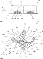
- the vehicle 101 is a low floor rail vehicle such as a tramway or the like.
- the vehicle 101 comprises a wagon body 101.1 supported by a suspension system on the running gear 102.
- the running gear 102 comprises two wheel units in the form of wheel sets 103 supporting a running gear frame 104 via a primary spring unit 105.
- the running gear frame 104 supports the wagon body via a secondary spring unit 106.
- the running gear frame 104 has a frame body 107 comprising two longitudinal beams 108 and a transverse beam unit 109 providing a structural connection between the longitudinal beams 108 in the transverse direction, such that a substantially H-shaped configuration is formed.
- Each longitudinal beam 108 has two free end sections 108.1 and a central section 108.2.
- the central section 108.2 is connected to the transverse beam unit 109 while the free end sections 108.1 form a primary suspension interface 110 for a primary suspension device 105.1 of the primary suspension unit 105 connected to the associated wheel unit 103.
- a compact and robust rubber-metal-spring is used for the primary spring device 105.1.
- Each longitudinal beam 108 has an angled section 108.3 associated to one of the free end sections 108.1.
- Each angled section 108.3 is arranged such that the free end section 108.1 forms a pillar section mainly extending in the height direction.
- the frame body 107 has a comparatively complex, generally three-dimensional geometry.
- Each longitudinal beam 108 has a pivot interface section 111 associated to the free end section 108.1.
- the pivot interface section 111 forms a pivot interface for a pivot arm 112 rigidly connected to a wheel set bearing unit 103.1 of the associated wheel unit 103.
- the pivot arm 112 is pivotably connected to the frame body 107 via a pivot bolt connection 113.
- the pivot bolt connection 113 comprises a pivot bolt 113.1 defining a pivot axis 113.2.
- the bolt 113.1 is inserted into matching recesses in a forked end of the pivot arm 112 and a pivot interface recess 111.1 in a lug 111.2 of the pivot interface section 111 (the lug 111.2 being received between the end parts of the pivot arm 112).
- the respective pivot interface section 111 is integrated into to the angled section 108.3 of the longitudinal beams 108, such that, nevertheless, a very compact arrangement is achieved. More precisely, integration of the pivot interface section 111 into the angled section 108.3 leads to a comparatively smooth, unbranched geometry of the frame body.
- the frame body 107 is formed as a monolithically cast component. More precisely, the frame body 107 is formed as a single piece cast in an automated casting process from a grey cast iron material.
- the grey cast iron material has the advantage that it comprises a particularly good flow capability during casting due to its high carbon content and thus leads to a very high level of process reliability.
- Casting is done in conventional molding boxes of an automated casting production line. Consequently, production of the frame body 107 is significantly simplified and rendered more cost effective than in conventional solutions with welded frame bodies. In fact, it has turned out that (compared to a conventional welded frame body) a cost reduction by more than 50% may be achieved with such an automated casting process.
- the grey cast iron material used in the present example is a so called nodular graphite iron cast material or spheroidal graphite iron (SGI) cast material as currently specified in European Norm EN 1563. More precisely, a material such as EN-GJS-400-18U LT is used, which provides a good compromise between strength, elongation at fracture and toughness, in particular at low temperatures. Obviously, depending on the mechanic requirements on the frame body, any other suitable cast material as outlined above may be used.
- the respective pivot interface section 111 in the longitudinal direction (x-axis), is arranged to be retracted behind the associated free end section 108.1.
- the maximum pivot interface dimension L PI,max is about 92% of the maximum longitudinal beam length L LB,max , thereby achieving a very compact design showing no longitudinal protrusion in the area at the pivot interface 111 and, hence, yielding appropriate boundary conditions for optimized material flow during casting which is essential in the automated casting process used.
- the forward pivot axis 113.2 (for the forward pivot arm 112) and the rearward pivot axis 113.2 (for the rearward pivot arm 112), in the longitudinal direction, define a pivot axis distance L PA being about 76% of the maximum longitudinal beam length L LB,max .
- the frame body 107 of the present embodiment is suitable for automated casting despite its considerable size in all three dimensions (x,y,z) in space, in particular, its considerable size not only in the "horizontal" plane (i.e. the xy-plane) but also its considerable size in the height direction (z-axis). More precisely, as can be seen from Figure 3 , in the height direction, the longitudinally central section 108.2 defines a longitudinal beam underside and a maximum central beam height H LBC,max of the longitudinal beam 108 above the longitudinal beam underside, while the free end sections 108.1 define a maximum beam height H LB,max above the longitudinal beam underside. Despite the fact that the maximum beam height H LB,max of the present embodiment is as high as about 380% of the maximum central beam height H LBC,max , the frame body 107 may be cast as a single monolithic component.
- a considerable reduction in the building space is accomplished in that the primary suspension interface 110 is configured such that the total resultant support force F TRS acting in the area of the respective free end 108.1 (i.e.
- Such an inclination of the total resultant support force F TRS allows the primary suspension device 105.1 to move closer to the wheel set 103, more precisely closer to the axis of rotation 103.2 of the wheel set 103.
- the pivot arm 112 connected to the wheel set bearing unit 103.1 can be of smaller, more lightweight and less complex design.
- such a design has the advantage that, not least due to the fact that the primary suspension interface section 110 moves closer to the wheel set 103, it further facilitates automated production of the frame body 107 using an automated casting process.
- the total resultant support force F TRS may have any desired and suitable inclination with respect to the longitudinal direction and the height direction
- Such an inclination provides a particularly compact and, hence, favorable design.
- the pillar section or end section 108.1 may be formed in a slightly forward leaning configuration which is favorable in terms of facilitating cast material flow and, hence, use of an automated casting process.
- the primary suspension interface 110 and the primary suspension device 105.1 are arranged such that the total resultant support force F TRS intersects a wheel set shaft 103.3 of the wheel set 103, leading to a favorable introduction of the support loads from the wheel set 103 into the primary suspension device 105.1 and onwards into the frame body 107. More precisely, the total resultant support force F TRS intersects the axis of wheel rotation 103.2 of the wheel shaft 103.3.
- Such a configuration leads to a comparatively short lever arm of the total resultant support force F TRS (for example, a lever arm A TRS at the location of the pivot bolt 113.1) and, hence, comparatively low bending moments acting in the longitudinal beam 108, which, in turn, allows a more lightweight design of the frame body 107.
- F TRS for example, a lever arm A TRS at the location of the pivot bolt 113.1
- a further advantage of the configuration as outlined above is the fact that the pivot arm 112 may have a very simple and compact design. More precisely, in the present example, the pivot arm 112 integrating the wheel set bearing unit 103.1, apart from the forked end section (receiving the pivot bolt 113.1) simply has to provide a corresponding support surface for the primary spring device 105.1 located close to the outer circumference of the wheel set bearing unit 103.1. Hence, compared to known configurations, no complex arms or the like are necessary for introducing the support forces into the primary spring device 105.1.
- the primary suspension interface 110 may have any desired shape
- the primary suspension interface 110 is a simple planar surface 110.1 laterally flanked by two protrusions 110.2 (against which mating surfaces of the primary suspension device 105.1 rest, among others, for centering purposes).
- the planar surface 110.1 defines a main interface plane configured to take a major fraction of the total resultant support force F TRS .
- the pivot interface section 111 in the longitudinal direction, is retracted behind a center 110.3 of the primary suspension interface 110.
- the pivot axis distance L PA is 82% of a primary suspension interface center distance L PSIC defined (in the longitudinal direction) by the centers 110.3 of a forward primary suspension interface 110 and a rearward primary suspension interface 110 of the longitudinal beams 108.
- the transverse beam unit 109 comprises two transverse beams 109.1, which are arranged to be substantially symmetric to each other with respect to a plane of symmetry parallel to the yz-plane and arranged centrally within the frame body 107.
- the transverse beams 109.1 (in the longitudinal direction) are separated by a gap 109.5.
- each transverse beam 109.1 in a sectional plane parallel to the xz-plane, has a substantially C-shaped cross section with an inner wall 109.2, an upper wall 109.3, and a lower wall 109.4.
- the C-shaped cross section is arranged such that, in the longitudinal direction, it is open towards the (more closely located) free end of the frame body 107, while it is substantially closed by the inner wall 109.2 located adjacent to the center of the frame body 107.
- the open sides of the transverse beams 109.1 are facing away from each other.
- Such an open design of the transverse beam 109.1 has the advantage that (despite the general rigidity of the materials used) not only the individual transverse beam 109.1 is comparatively torsionally soft, i.e. shows a comparatively low resistance against torsional moments about the transverse y-axis (compared to a closed, generally box shaped design of the transverse beam).
- the gap 109.5 in a central area of the frame body 107, has a maximum longitudinal gap dimension L G,max , which is about 100% of a minimum longitudinal dimension L TB,min of one of the transverse beams 109.1 in the longitudinal direction (in the central area of the frame body 107).
- the gap 109.5 has the advantage that the bending resistance in the plane of main extension of the two transverse beams 109.1 (parallel to the xy-plane) is increased without adding to the mass of the frame body 107, such that a comparatively lightweight configuration is achieved.
- the gap 109.5 is readily available for receiving other components of the running gear 102 (such as a transverse damper 114 as shown in Figure 6 ), which is particularly beneficial in modern rail vehicles with their severe constraints regarding the building space available.
- the C-shaped cross section extends over a transversally central section of the transverse beam unit 109, since, at this location, a particularly beneficial influence on the torsional rigidity of the transverse beam unit is achieved.
- the substantially C-shaped cross section extends over the entire extension of the transverse beam unit in the transverse direction (i.e. from one longitudinal beam 108 to the other longitudinal beam 108).
- the C-shaped cross section extends over a transverse dimension W TBC , which is 85% of a transverse distance W LBC between longitudinal center lines 108.4 of the longitudinal beams 108 in the area of the transverse beam unit 109.
- the same (as for the C-shaped cross-section) also applies to the extension of the gap 109.5.
- the longitudinal gap dimension doesn't necessarily have to be the same along the transverse direction. Any desired gap width may be chosen as needed.
- each transverse beam 109.1 defines a transverse beam center line 109.6, which has a generally curved or polygonal shape in a first plane parallel to the xy-plane and in a second plane parallel to the yz-plane.
- Such generally curved or polygonal shapes of the transverse beam center lines 109.6 have the advantage that the shape of the respective transverse beam 109.1 is adapted to the distribution of the loads acting on the respective transverse beam 109.1 resulting in a comparatively smooth distribution of the stresses within the respective transverse beam 109.1 and, ultimately, in a comparatively lightweight and stress optimized frame body 107.
- the transverse beam unit 109 is a centrally waisted unit with a waisted central section 109.7 defining a minimum longitudinal dimension of the transverse beam unit L TBU,min (in the longitudinal direction) which, in the present example, is 65% of a maximum longitudinal dimension of the transverse beam unit L TBU,max (in the longitudinal direction).
- This maximum longitudinal dimension in the present example, is defined at the junction of the transverse beam unit 109 and the longitudinal beams 108.
- the extent of the waist of the transverse beam unit 109 may be chosen as a function of the mechanical properties of the frame body 107 (in particular, the torsional rigidity of the frame body 107) to be achieved.
- the transverse beam unit design as outlined herein a well-balanced configuration is achieved showing both, comparatively low torsional rigidity (about the transverse direction) and comparatively high bending rigidity (about the height direction).
- This configuration is particularly advantageous with respect to the derailment safety of the running gear 102 since the running gear frame 104 is able to provide some torsional deformation tending to equalize the wheel to rail contact forces on all four wheels of the wheel sets 103.
- the free end section 108.1 in a section facing away from the primary spring interface 110, forms a stop interface for a stop device 115.
- the stop devices 115 integrate the functionality of a rotational stop device and a longitudinal stop device for the wagon body 101.1. Furthermore, the stop devices 115 also are adapted to form a traction link between the frame body 107 and the wagon body 101.1 supported on the frame body 107. It will be appreciated that such a configuration is particularly beneficial since it provides a high degree of functional integration leading to a comparatively lightweight overall design.
- the wagon body 101.1 (more precisely, either the same part of the wagon body 101.1 also supported on the first running gear 102 or another part of the wagon body 101) is supported on a further, second running gear 116.
- the second running gear 116 is identical to the first running the 102 in all the parts described above.
- the first running gear 102 is a driven running gear with a drive unit (not shown) mounted to the frame body 107
- the second running gear 116 is a non-driven running gear, having no such drive unit mounted to the frame body 107.
- the frame body 107 forms a standardized component which used for both, the first running gear 102 and the second running gear, i.e. different types of running gear.
- Customization of the respective frame body 107 to the specific type of running gear type may be achieved by additional type specific components mounted to the standardized frame body 107.
- Such an approach is highly advantageous in terms of its commercial impact. This is due to the fact that, in addition to the considerable savings achieved due to the automated casting process, only one single type of frame body 107 has to be manufactured, which brings along a further considerable reduction in costs.
- customization of the running gear 102, 116 to a specific type or function on the basis of identical frame bodies 107 is not limited to a differentiation in terms of driven and non-driven running gears. Any other functional components (such as e.g. specific types of brakes, tilt systems, rolling support systems such as an anti-roll-bar device, etc.) may be used to achieve a corresponding functional differentiation between such running gears on the basis of standardized identical frame bodies 107.
- Any other functional components such as e.g. specific types of brakes, tilt systems, rolling support systems such as an anti-roll-bar device, etc.
Landscapes
- Engineering & Computer Science (AREA)
- Mechanical Engineering (AREA)
- Transportation (AREA)
- Vehicle Body Suspensions (AREA)
- Body Structure For Vehicles (AREA)
Claims (15)
- Cadre de train de roulement pour un véhicule ferroviaire, comprenant- un corps de cadre (107) définissant une direction longitudinale, une direction transversale et une direction de hauteur;- ledit corps de cadre (107) comprenant deux poutres longitudinales (108) et une unité de poutre transversale (109) assurant une connexion structurelle entre lesdites poutres longitudinales (108) dans ladite direction transversale, de sorte qu'une configuration sensiblement en forme de H est formée,- ladite unité de poutre transversale (109) comprend au moins une poutre transversale (109.1),- chaque poutre longitudinale (108) ayant une section d'extrémité libre (108.1) formant une interface de suspension primaire (110) pour un dispositif de suspension primaire (105.1) relié à une unité de roue associée (103);- chaque poutre longitudinale (108) ayant une section d'interface de pivot (111) associée à ladite section d'extrémité libre (108.1) et formant une interface de pivot pour un bras de pivot (112) connecté à ladite unité de roue associée (103);- chaque poutre longitudinale (108) ayant une section coudée (108.3) associée à ladite section d'extrémité libre (108.1);- ladite section coudée (108.3) étant agencée de telle sorte que ladite section d'extrémité libre (108.1) forme une section de pilier s'étendant au moins principalement dans ladite direction de hauteur;- ladite section d'interface pivot (111) étant associée à ladite section coudée (108.3);- ladite section d'interface pivot (111) est intégrée dans ladite section coudée (108.3), et- ledit corps de cadre (107) est réalisé sous la forme d'un composant coulé monolithiquement constitué d'un matériau en fonte grise.caractérisé en ce que- ladite au moins une poutre transversale (109.1), dans un plan de coupe parallèle à ladite direction longitudinale et à ladite direction de hauteur, définissant une section transversale sensiblement en forme de C;
- Cadre de train de roulement selon la revendication 1, dans lequel- ledit corps de cadre (107) est fait d'un matériau moulé en fonte à graphite sphéroïdal;- ledit matériau de fonte à graphite sphéroïdal, en particulier, étant l'un des EN-GJS-400-18U LT et EN-GJS-350-22-LT.
- Cadre de train de roulement selon la revendication 1 ou 2, dans lequel- ladite section d'interface de pivot (111), dans ladite direction longitudinale, est agencée pour être au moins partiellement rétractée derrière ladite section d'extrémité libre associée (108.1);- une section d'extrémité libre avant (108.1) et une section d'extrémité libre arrière (108.1) d'une desdites poutres longitudinales (108), dans ladite direction longitudinale, définissant une longueur de poutre longitudinale maximale de ladite poutre longitudinale (108);- une section d'interface de pivot avant (111) étant associée à ladite section d'extrémité libre avant (108.1);- une section d'interface de pivot arrière (111) étant associée à ladite section d'extrémité libre arrière (108.1);- ladite section d'interface de pivot avant (111) et ladite section d'interface de pivot arrière (111), dans ladite direction longitudinale, définissant une dimension maximale d'interface de pivot de ladite poutre longitudinale (108);- ladite dimension maximale de l'interface de pivot, en particulier, étant de 70% à 110%, de préférence de 80% à 105%, plus préférentiellement de 90% à 95%, de ladite longueur de poutre longitudinale maximale.
- Cadre de train de roulement selon la revendication 3, dans lequel- une section d'interface de pivot avant (111) associée à ladite section d'extrémité libre avant (108.1) définit un axe de pivot avant (113.2) pour un bras de pivot avant (112);- une section d'interface de pivot arrière (111) associée à ladite section d'extrémité libre arrière (108.1) définit un axe de pivot arrière (113.2) pour un bras de pivot arrière (112);- ledit axe de pivot avant (113.2) et ledit axe de pivot arrière (113.2), dans ladite direction longitudinale, définissant une distance d'axe de pivot;- ladite distance d'axe de pivot étant de 60% à 90%, de préférence 70% à 80%, plus préférablement 72% à 78%, de ladite longueur de poutre longitudinale maximale.
- Cadre de train de roulement selon l'une des revendications 1 à 4, dans lequel,- dans ladite direction de hauteur, l'une desdites poutres longitudinales (108), dans une section longitudinalement centrale, définit une face inférieure de poutre longitudinale et une hauteur de poutre centrale maximale de ladite poutre longitudinale (108) au-dessus de ladite face inférieure de poutre longitudinale, et- l'une desdites sections d'extrémité libres (108.1) de ladite poutre longitudinale (108) définit une hauteur maximale de poutre au-dessus de ladite face inférieure de poutre longitudinale;- ladite hauteur maximale de poutre étant de 200% à 450%, de préférence de 300% à 400%, plus préférablement de 370% à 380%, de ladite hauteur maximale de poutre centrale.
- Cadre de train de roulement selon l'une des revendications 1 à 5, dans lequel,- ladite interface de suspension principale (110) est configurée pour prendre une force de support résultante totale agissant sur ladite section d'extrémité libre (108.1) lorsque ledit corps de cadre (107) est supporté sur ladite unité de roue associée (103);- ladite interface de suspension principale (110) étant configurée de telle sorte que ladite force de support résultante totale est inclinée par rapport à ladite direction longitudinale et / ou inclinée par rapport à ladite direction de hauteur;- ladite force d'appui totale résultante, en particulier, étant inclinée par rapport à ladite direction de hauteur d'un angle de suspension primaire, ledit angle de suspension primaire allant de 20° à 80°, de préférence de 30° à 70°, plus préférentiellement de 40° à 50°.
- Cadre de train de roulement selon la revendication 6, dans lequel,- ladite interface de suspension primaire (110) définit un plan d'interface principal;- ledit plan d'interface principal étant configuré pour prendre au moins une fraction majeure de ladite force de support résultante;- ledit plan d'interface principal étant incliné par rapport à ladite direction longitudinale et / ou incliné par rapport à ladite direction de hauteur;- ledit plan d'interface principal, en particulier, étant incliné par rapport à ladite direction de la hauteur d'un angle du plan d'interface principal, ledit angle du plan d'interface principal allant de 20° à 80°, de préférence de 30° à 70°, plus préférentiellement de 40° à 50°;- ledit plan d'interface principal, en particulier, étant sensiblement parallèle par rapport à ladite direction transversale.
- Cadre de train de roulement selon la revendication 6 ou 7, dans lequel,- ladite section d'interface de pivot (111), dans ladite direction longitudinale, est agencée pour être au moins partiellement rétractée derrière un centre (110.3) de ladite interface de suspension primaire (110);- un centre (110.3) d'une interface de suspension primaire avant (110) et un centre (110.3) d'une interface de suspension primaire arrière (110) d'une desdites poutres longitudinales (108), dans ladite direction longitudinale, définissant une distance de centre d'interface de suspension primaire;- une section d'interface de pivot avant (111) étant associée à ladite interface de suspension primaire avant (110) et définissant un axe de pivot avant (113.2) pour un bras de pivot avant (112);- une section d'interface de pivot arrière (111) étant associée à ladite interface de suspension primaire arrière (110) et définissant un axe de pivot arrière (113.2) pour un bras de pivot arrière (112);- ledit axe de pivot avant (113.2) et ledit axe de pivot arrière (113.2), dans ladite direction longitudinale, définissant une distance d'axe de pivotement;- ladite distance d'axe de pivot étant de 60% à 105%, de préférence 70% à 95%, plus préférablement 80% à 85%, de ladite distance de centre d'interface de suspension primaire.
- Cadre de train de roulement selon l'une des revendications 6 à 8, dans lequel,- ladite interface de suspension primaire (110) est configurée comme une interface pour un seul dispositif de suspension primaire (105.1);- ledit dispositif de suspension primaire (105.1), en particulier, étant formé par une seule unité de suspension primaire;- ladite unité de suspension primaire (105.1), en particulier, étant formée d'un seul ressort de suspension primaire, de préférence une unité de ressort caoutchouc- métal.
- Cadre de train de roulement selon l'une des revendications 1 à 9, dans lequel,- ladite section transversale sensiblement en forme de C est agencée de telle sorte que, dans ladite direction longitudinale, elle soit ouverte vers une extrémité libre dudit corps de cadre (107) et, en particulier, sensiblement fermée vers un centre dudit corps de cadre ;
et/ou- ladite section transversale sensiblement en forme de C s'étend, dans ladite direction transversale, sur une section transversale centrale de ladite unité de poutre transversale (109);
et/ou- ladite section transversale sensiblement en forme de C s'étend, dans ladite direction transversale, sur une dimension transversale, ladite dimension transversale étant d'au moins 50%, de préférence d'au moins 70%, plus préférentiellement de 80% à 95%, d'une distance entre les lignes médianes longitudinales desdites poutres longitudinales (108) dans la zone de ladite unité de poutre transversale (109). - Cadre de train de roulement selon l'une des revendications 1 à 10, dans lequel,- ladite au moins une poutre transversale (109.1) est une première poutre transversale (109.1) et ladite unité de poutre transversale (109) comprend une deuxième poutre transversale (109.1);- ladite première poutre transversale (109.1) et ladite deuxième poutre transversale (109.1), en particulier, étant sensiblement symétriques par rapport à un plan de symétrie parallèle à ladite direction transversale et à ladite direction de la hauteur;- ladite première poutre transversale (109.1) et ladite deuxième poutre transversale (109.1), en particulier, étant séparées, dans ladite direction longitudinale, par un espace (109.5) ayant une dimension d'intervalle longitudinal;- ladite dimension d'intervalle longitudinal, en particulier, étant de 70% à 120%, de préférence de 85% à 110%, mieux encore de 95% à 105%, d'une dimension longitudinale minimale d'une desdites poutres transversales (109.1) dans ladite direction longitudinale;- ladite première poutre transversale (109.1) et ladite seconde poutre transversale (109.1), en particulier, chacune définissant une ligne médiane de poutre transversale (109.6), au moins l'une desdites lignes médianes transversales de poutre (109.6), au moins en section, ayant une forme généralement courbe ou polygonale dans un premier plan parallèle à ladite direction longitudinale et à ladite direction transversale et / ou un second plan parallèle à ladite direction transversale et à ladite direction de la hauteur.
- Cadre de train de roulement selon l'une des revendications 1 à 11, dans lequel,- ladite unité de poutre transversale (109) est une unité cintrée localement, en particulier une unité cintrée centralement;- ladite unité de poutre transversale (109) ayant une section cintrée (109.7) définissant une dimension longitudinale minimale de ladite unité de poutre transversale (109) dans ladite direction longitudinale;- ladite dimension longitudinale minimale de ladite unité de poutre transversale (109), en particulier, étant de 40% à 90%, de préférence de 50% à 80%, plus préférablement de 60% à 70%, d'une dimension longitudinale maximale de ladite unité de poutre transversale (109) dans ladite direction longitudinale, ladite dimension longitudinale maximale, en particulier, étant définie à une jonction de ladite unité de poutre transversale (109) et de l'une desdites poutres longitudinales (108).
- Cadre de train de roulement selon l'une des revendications 1 à 12, dans lequel,- ladite section d'extrémité libre (108.1), dans une section opposée à ladite interface de ressort primaire, forme une interface d'arrêt pour un dispositif d'arrêt (115);- ledit dispositif d'arrêt (115), en particulier, étant un dispositif d'arrêt en rotation et / ou un dispositif d'arrêt longitudinal;- ledit dispositif d'arrêt (115), en particulier, étant adapté pour former une liaison de traction entre ledit corps de cadre (107) et un composant, notamment un traversin ou une caisse de wagon (101.1), supporté sur ledit corps de cadre (107).
- Unité de véhicule ferroviaire, comprenant- une première unité de train de roulement (104) selon l'une des revendications 1 à 14 supportée sur deux unités de roue (103) via des unités de ressort primaires (105) et des bras pivotants (112) reliés à un corps de cadre (107) de ladite première unité de train de roulement (104) pour former un premier train de roulement (102);- un composant de véhicule ferroviaire (101.1), en particulier, étant supporté sur ledit corps de cadre (107), ledit composant de véhicule ferroviaire, en particulier, étant un traversin ou une caisse de wagon (101.1);- ladite unité de véhicule ferroviaire, en particulier, comprenant une deuxième unité de train de roulement (104) selon l'une des revendications 1 à 14 supportée sur deux unités de roues (103) via des unités de ressort primaires (105) et des bras de pivot (112) reliés à un corps de cadre (107) de ladite deuxième unité de train de roulement (104) pour former un deuxième train de roulement (116);- ledit premier train de roulement (102), en particulier, étant un train de roulement moteur comprenant une unité d'entraînement, ledit deuxième train de roulement (116), en particulier, étant un train de roulement roulant sans unité d'entraînement, au moins ledit cadre le corps (107) dudit premier cadre de train de roulement (104) et ledit corps de cadre (107) dudit second cadre de train de roulement (104), en particulier, étant sensiblement identiques.
- Procédé de production d'un cadre de train de roulement selon l'une des revendications 1 à 13, dans lequel ledit corps de cadre (107) est coulé en une seule étape, en particulier, dans un processus de coulée automatisé.
Priority Applications (12)
| Application Number | Priority Date | Filing Date | Title |
|---|---|---|---|
| ES12170083T ES2880707T3 (es) | 2012-05-30 | 2012-05-30 | Bastidor de tren de rodaje para vehículo ferroviario |
| EP12170083.5A EP2669138B1 (fr) | 2012-05-30 | 2012-05-30 | Cadre de train roulant de véhicule ferroviaire |
| PL12170083T PL2669138T3 (pl) | 2012-05-30 | 2012-05-30 | Rama podwozia dla pojazdu szynowego |
| CN202010229561.4A CN111361594B (zh) | 2012-05-30 | 2012-11-30 | 一种轨道车辆的运行装置框架及其轨道车辆单元 |
| CN2012206513182U CN203255204U (zh) | 2012-05-30 | 2012-11-30 | 一种轨道车辆的运行装置框架及其轨道车辆单元 |
| CN2012105046799A CN103465924A (zh) | 2012-05-30 | 2012-11-30 | 一种轨道车辆的运行装置框架 |
| CA2874801A CA2874801C (fr) | 2012-05-30 | 2013-05-29 | Chassis d'organe de roulement pour vehicule ferroviaire |
| RU2014153505A RU2622167C2 (ru) | 2012-05-30 | 2013-05-29 | Рама ходовой части рельсового транспортного средства |
| US14/403,745 US9919719B2 (en) | 2012-05-30 | 2013-05-29 | Running gear frame for a rail vehicle |
| BR112014029652A BR112014029652A2 (pt) | 2012-05-30 | 2013-05-29 | armação da engrenagem de marcha para veículo ferroviário, unidade de veículo ferroviário e método para a produção de armação da engrenagem de marcha |
| AU2013269633A AU2013269633B2 (en) | 2012-05-30 | 2013-05-29 | Running gear frame for a rail vehicle |
| PCT/EP2013/061133 WO2013178717A1 (fr) | 2012-05-30 | 2013-05-29 | Châssis d'organe de roulement pour véhicule ferroviaire |
Applications Claiming Priority (1)
| Application Number | Priority Date | Filing Date | Title |
|---|---|---|---|
| EP12170083.5A EP2669138B1 (fr) | 2012-05-30 | 2012-05-30 | Cadre de train roulant de véhicule ferroviaire |
Publications (2)
| Publication Number | Publication Date |
|---|---|
| EP2669138A1 EP2669138A1 (fr) | 2013-12-04 |
| EP2669138B1 true EP2669138B1 (fr) | 2021-07-07 |
Family
ID=48576407
Family Applications (1)
| Application Number | Title | Priority Date | Filing Date |
|---|---|---|---|
| EP12170083.5A Active EP2669138B1 (fr) | 2012-05-30 | 2012-05-30 | Cadre de train roulant de véhicule ferroviaire |
Country Status (10)
| Country | Link |
|---|---|
| US (1) | US9919719B2 (fr) |
| EP (1) | EP2669138B1 (fr) |
| CN (3) | CN203255204U (fr) |
| AU (1) | AU2013269633B2 (fr) |
| BR (1) | BR112014029652A2 (fr) |
| CA (1) | CA2874801C (fr) |
| ES (1) | ES2880707T3 (fr) |
| PL (1) | PL2669138T3 (fr) |
| RU (1) | RU2622167C2 (fr) |
| WO (1) | WO2013178717A1 (fr) |
Cited By (1)
| Publication number | Priority date | Publication date | Assignee | Title |
|---|---|---|---|---|
| EP4304106A1 (fr) | 2022-07-07 | 2024-01-10 | Thales | Système de radiocommunications satellitaire multifaisceaux passif sans redondance |
Families Citing this family (9)
| Publication number | Priority date | Publication date | Assignee | Title |
|---|---|---|---|---|
| EP2669135B1 (fr) * | 2012-05-30 | 2015-01-14 | Bombardier Transportation GmbH | Agencement de commande pour train roulant |
| ES2880707T3 (es) * | 2012-05-30 | 2021-11-25 | Bombardier Transp Gmbh | Bastidor de tren de rodaje para vehículo ferroviario |
| AT516924A2 (de) | 2015-03-03 | 2016-09-15 | Siemens Ag Oesterreich | Fahrwerksrahmen für ein Schienenfahrzeug |
| CN104890693B (zh) * | 2015-06-29 | 2017-06-23 | 南车株洲电力机车有限公司 | 一种轨道车辆 |
| CN107292967B (zh) * | 2017-06-23 | 2021-06-18 | 艾凯克斯(嘉兴)信息科技有限公司 | 基于几何特征映射搭建含有骨架的三维可配置bom的方法 |
| CN107600933A (zh) * | 2017-09-30 | 2018-01-19 | 广西路桥工程集团有限公司 | 运拱平车 |
| DE202017107670U1 (de) | 2017-12-18 | 2019-03-20 | Lothar Thoni | Drehgestellrahmen für Schienenfahrzeuge aus einem Aluminiumgussteil |
| PL3572294T3 (pl) | 2018-05-25 | 2021-08-16 | Bombardier Transportation Gmbh | Rama podwozia dla pojazdu szynowego |
| EP3851355B1 (fr) * | 2020-01-17 | 2023-06-07 | HEMSCHEIDT Engineering GmbH & Co. KG | Axe portatif pour un bogie d'un véhicule ferroviaire |
Citations (2)
| Publication number | Priority date | Publication date | Assignee | Title |
|---|---|---|---|---|
| EP0564423A1 (fr) * | 1992-04-03 | 1993-10-06 | FIAT FERROVIARIA S.p.A. | Chassis d'un bogie ferroviaire |
| EP1415882A1 (fr) * | 2002-10-30 | 2004-05-06 | Kawasaki Jukogyo Kabushiki Kaisha | Bogie pour un véhicule ferroviaire |
Family Cites Families (27)
| Publication number | Priority date | Publication date | Assignee | Title |
|---|---|---|---|---|
| BE383940A (fr) * | ||||
| SU827A1 (ru) * | 1923-04-30 | 1924-09-15 | П.Я. Абалдуев | Лита рама дл паровозов |
| FR651467A (fr) * | 1927-09-07 | 1929-02-19 | Procédé de fabrication de châssis de trucks pour matériel roulant et châssis ainsi obtenus | |
| US3547046A (en) | 1968-04-16 | 1970-12-15 | Gen Steel Ind Inc | Railway locomotive truck with low traction point |
| US3945325A (en) * | 1971-06-04 | 1976-03-23 | Swiss Aluminium Ltd. | Railway bogie |
| FR2280536A1 (fr) * | 1974-08-02 | 1976-02-27 | Creusot Loire | Dispositif de soutien d'inducteurs lineaires sur un bogie ferroviaire |
| US4428301A (en) * | 1981-08-03 | 1984-01-31 | Lukens General Industries, Inc. | Radial axle railway truck |
| DE3232289A1 (de) * | 1981-08-31 | 1983-03-24 | South African Inventions Development Corp., Pretoria, Transvaal | Eisenbahnwagen |
| NL8700924A (nl) * | 1987-04-16 | 1988-11-16 | Werkspoor Services Bv | Railvoertuig en draaistel daarvoor. |
| FR2632594A1 (fr) * | 1988-06-08 | 1989-12-15 | Alsthom Creusot Rail | Chassis de bogie |
| DE4136926A1 (de) | 1991-11-11 | 1993-05-13 | Abb Henschel Waggon Union | Fahrwerk fuer niederflurbahnen |
| DE4214066C2 (de) * | 1992-04-29 | 1994-07-14 | Siemens Ag | Fahrwerk für ein Schienenfahrzeug |
| DE4428038C1 (de) * | 1994-08-08 | 1995-08-10 | Siemens Ag | Fahrwerk für ein Schienenfahrzeug |
| US5752564A (en) | 1997-01-08 | 1998-05-19 | Amsted Industries Incorporated | Railway truck castings and method and cores for making castings |
| AT405391B (de) * | 1997-02-11 | 1999-07-26 | Siemens Sgp Verkehrstech Gmbh | Drehgestell eines schienenfahrzeuges und verfahren zu dessen herstellung |
| CN2515076Y (zh) * | 2001-12-28 | 2002-10-09 | 湘潭电机股份有限公司 | 低地板轻轨车拖动转向架 |
| KR100586537B1 (ko) | 2005-03-08 | 2006-06-08 | 이용봉 | 궤도차량용 전차대 회전장치 |
| DE102005038274C5 (de) * | 2005-08-12 | 2018-01-11 | Saf-Holland Gmbh | Radaufhängungslenker |
| DE102006029835A1 (de) * | 2006-06-27 | 2008-01-03 | Bombardier Transportation Gmbh | Fahrwerksrahmen eines Schienenfahrzeugs |
| JP4692578B2 (ja) * | 2008-05-30 | 2011-06-01 | トヨタ自動車株式会社 | 車両のサスペンションアーム |
| AT507754A1 (de) * | 2008-12-22 | 2010-07-15 | Siemens Ag Oesterreich | Primärfeder |
| RU2544259C2 (ru) * | 2009-07-16 | 2015-03-20 | Сименс Аг Эстеррайх | Рама ходовой части для рельсовых транспортных средств |
| DE202011004025U1 (de) * | 2011-03-16 | 2012-07-10 | Bombardier Transportation Gmbh | Fahrwerksrahmen für ein Fahrwerk eines Schienenfahrzeugs |
| DE102011110090A1 (de) | 2011-08-12 | 2013-02-14 | Bombardier Transportation Gmbh | Radträgeranlenkung für ein Schienenfahrzeug |
| CN202413825U (zh) * | 2011-12-12 | 2012-09-05 | 南车南京浦镇车辆有限公司 | 轮对提吊机构 |
| ES2880707T3 (es) * | 2012-05-30 | 2021-11-25 | Bombardier Transp Gmbh | Bastidor de tren de rodaje para vehículo ferroviario |
| EP2669136B1 (fr) * | 2012-05-30 | 2020-01-01 | Bombardier Transportation GmbH | Unité de véhicule ferroviaire |
-
2012
- 2012-05-30 ES ES12170083T patent/ES2880707T3/es active Active
- 2012-05-30 EP EP12170083.5A patent/EP2669138B1/fr active Active
- 2012-05-30 PL PL12170083T patent/PL2669138T3/pl unknown
- 2012-11-30 CN CN2012206513182U patent/CN203255204U/zh not_active Expired - Lifetime
- 2012-11-30 CN CN202010229561.4A patent/CN111361594B/zh active Active
- 2012-11-30 CN CN2012105046799A patent/CN103465924A/zh active Pending
-
2013
- 2013-05-29 CA CA2874801A patent/CA2874801C/fr active Active
- 2013-05-29 US US14/403,745 patent/US9919719B2/en active Active
- 2013-05-29 WO PCT/EP2013/061133 patent/WO2013178717A1/fr active Application Filing
- 2013-05-29 BR BR112014029652A patent/BR112014029652A2/pt active Search and Examination
- 2013-05-29 AU AU2013269633A patent/AU2013269633B2/en active Active
- 2013-05-29 RU RU2014153505A patent/RU2622167C2/ru active
Patent Citations (2)
| Publication number | Priority date | Publication date | Assignee | Title |
|---|---|---|---|---|
| EP0564423A1 (fr) * | 1992-04-03 | 1993-10-06 | FIAT FERROVIARIA S.p.A. | Chassis d'un bogie ferroviaire |
| EP1415882A1 (fr) * | 2002-10-30 | 2004-05-06 | Kawasaki Jukogyo Kabushiki Kaisha | Bogie pour un véhicule ferroviaire |
Cited By (1)
| Publication number | Priority date | Publication date | Assignee | Title |
|---|---|---|---|---|
| EP4304106A1 (fr) | 2022-07-07 | 2024-01-10 | Thales | Système de radiocommunications satellitaire multifaisceaux passif sans redondance |
Also Published As
| Publication number | Publication date |
|---|---|
| RU2622167C2 (ru) | 2017-06-13 |
| AU2013269633A1 (en) | 2014-12-18 |
| WO2013178717A1 (fr) | 2013-12-05 |
| CA2874801C (fr) | 2017-08-01 |
| CA2874801A1 (fr) | 2013-12-05 |
| CN203255204U (zh) | 2013-10-30 |
| CN103465924A (zh) | 2013-12-25 |
| RU2014153505A (ru) | 2016-07-20 |
| CN111361594A (zh) | 2020-07-03 |
| AU2013269633B2 (en) | 2016-08-11 |
| PL2669138T3 (pl) | 2021-12-27 |
| CN111361594B (zh) | 2021-11-30 |
| US9919719B2 (en) | 2018-03-20 |
| US20150144025A1 (en) | 2015-05-28 |
| EP2669138A1 (fr) | 2013-12-04 |
| ES2880707T3 (es) | 2021-11-25 |
| BR112014029652A2 (pt) | 2017-06-27 |
Similar Documents
| Publication | Publication Date | Title |
|---|---|---|
| EP2557015B1 (fr) | Unité de train de roulement pour un véhicule ferroviaire | |
| EP2669138B1 (fr) | Cadre de train roulant de véhicule ferroviaire | |
| KR101436128B1 (ko) | 궤도 차량의 주행 기어 프레임 | |
| CN103465923B (zh) | 轨道车辆单元 | |
| EP2669137B1 (fr) | Dispositif à ressort pour véhicule ferroviaire | |
| CN101011973B (zh) | 用于低高度底盘轨道车辆的车轴、悬架装置及轨道车辆 | |
| EP2500233B1 (fr) | Unité de véhicule ferroviaire avec liaison de traction | |
| CA2874732C (fr) | Unite d'organe roulant pour vehicule ferroviaire | |
| EP2500232B1 (fr) | Cadre de train roulant à poids réduit pour véhicule ferroviaire |
Legal Events
| Date | Code | Title | Description |
|---|---|---|---|
| PUAI | Public reference made under article 153(3) epc to a published international application that has entered the european phase |
Free format text: ORIGINAL CODE: 0009012 |
|
| AK | Designated contracting states |
Kind code of ref document: A1 Designated state(s): AL AT BE BG CH CY CZ DE DK EE ES FI FR GB GR HR HU IE IS IT LI LT LU LV MC MK MT NL NO PL PT RO RS SE SI SK SM TR |
|
| AX | Request for extension of the european patent |
Extension state: BA ME |
|
| 17P | Request for examination filed |
Effective date: 20140603 |
|
| RBV | Designated contracting states (corrected) |
Designated state(s): AL AT BE BG CH CY CZ DE DK EE ES FI FR GB GR HR HU IE IS IT LI LT LU LV MC MK MT NL NO PL PT RO RS SE SI SK SM TR |
|
| STAA | Information on the status of an ep patent application or granted ep patent |
Free format text: STATUS: EXAMINATION IS IN PROGRESS |
|
| 17Q | First examination report despatched |
Effective date: 20171222 |
|
| GRAP | Despatch of communication of intention to grant a patent |
Free format text: ORIGINAL CODE: EPIDOSNIGR1 |
|
| STAA | Information on the status of an ep patent application or granted ep patent |
Free format text: STATUS: GRANT OF PATENT IS INTENDED |
|
| INTG | Intention to grant announced |
Effective date: 20210120 |
|
| RAP3 | Party data changed (applicant data changed or rights of an application transferred) |
Owner name: BOMBARDIER TRANSPORTATION GMBH |
|
| GRAS | Grant fee paid |
Free format text: ORIGINAL CODE: EPIDOSNIGR3 |
|
| GRAA | (expected) grant |
Free format text: ORIGINAL CODE: 0009210 |
|
| STAA | Information on the status of an ep patent application or granted ep patent |
Free format text: STATUS: THE PATENT HAS BEEN GRANTED |
|
| AK | Designated contracting states |
Kind code of ref document: B1 Designated state(s): AL AT BE BG CH CY CZ DE DK EE ES FI FR GB GR HR HU IE IS IT LI LT LU LV MC MK MT NL NO PL PT RO RS SE SI SK SM TR |
|
| REG | Reference to a national code |
Ref country code: GB Ref legal event code: FG4D |
|
| REG | Reference to a national code |
Ref country code: AT Ref legal event code: REF Ref document number: 1408312 Country of ref document: AT Kind code of ref document: T Effective date: 20210715 |
|
| REG | Reference to a national code |
Ref country code: DE Ref legal event code: R096 Ref document number: 602012076025 Country of ref document: DE |
|
| REG | Reference to a national code |
Ref country code: IE Ref legal event code: FG4D |
|
| REG | Reference to a national code |
Ref country code: SE Ref legal event code: TRGR |
|
| REG | Reference to a national code |
Ref country code: LT Ref legal event code: MG9D |
|
| REG | Reference to a national code |
Ref country code: NL Ref legal event code: MP Effective date: 20210707 |
|
| REG | Reference to a national code |
Ref country code: ES Ref legal event code: FG2A Ref document number: 2880707 Country of ref document: ES Kind code of ref document: T3 Effective date: 20211125 |
|
| PG25 | Lapsed in a contracting state [announced via postgrant information from national office to epo] |
Ref country code: HR Free format text: LAPSE BECAUSE OF FAILURE TO SUBMIT A TRANSLATION OF THE DESCRIPTION OR TO PAY THE FEE WITHIN THE PRESCRIBED TIME-LIMIT Effective date: 20210707 Ref country code: NO Free format text: LAPSE BECAUSE OF FAILURE TO SUBMIT A TRANSLATION OF THE DESCRIPTION OR TO PAY THE FEE WITHIN THE PRESCRIBED TIME-LIMIT Effective date: 20211007 Ref country code: RS Free format text: LAPSE BECAUSE OF FAILURE TO SUBMIT A TRANSLATION OF THE DESCRIPTION OR TO PAY THE FEE WITHIN THE PRESCRIBED TIME-LIMIT Effective date: 20210707 Ref country code: PT Free format text: LAPSE BECAUSE OF FAILURE TO SUBMIT A TRANSLATION OF THE DESCRIPTION OR TO PAY THE FEE WITHIN THE PRESCRIBED TIME-LIMIT Effective date: 20211108 Ref country code: NL Free format text: LAPSE BECAUSE OF FAILURE TO SUBMIT A TRANSLATION OF THE DESCRIPTION OR TO PAY THE FEE WITHIN THE PRESCRIBED TIME-LIMIT Effective date: 20210707 Ref country code: FI Free format text: LAPSE BECAUSE OF FAILURE TO SUBMIT A TRANSLATION OF THE DESCRIPTION OR TO PAY THE FEE WITHIN THE PRESCRIBED TIME-LIMIT Effective date: 20210707 Ref country code: BG Free format text: LAPSE BECAUSE OF FAILURE TO SUBMIT A TRANSLATION OF THE DESCRIPTION OR TO PAY THE FEE WITHIN THE PRESCRIBED TIME-LIMIT Effective date: 20211007 Ref country code: LT Free format text: LAPSE BECAUSE OF FAILURE TO SUBMIT A TRANSLATION OF THE DESCRIPTION OR TO PAY THE FEE WITHIN THE PRESCRIBED TIME-LIMIT Effective date: 20210707 |
|
| PG25 | Lapsed in a contracting state [announced via postgrant information from national office to epo] |
Ref country code: LV Free format text: LAPSE BECAUSE OF FAILURE TO SUBMIT A TRANSLATION OF THE DESCRIPTION OR TO PAY THE FEE WITHIN THE PRESCRIBED TIME-LIMIT Effective date: 20210707 Ref country code: GR Free format text: LAPSE BECAUSE OF FAILURE TO SUBMIT A TRANSLATION OF THE DESCRIPTION OR TO PAY THE FEE WITHIN THE PRESCRIBED TIME-LIMIT Effective date: 20211008 |
|
| REG | Reference to a national code |
Ref country code: DE Ref legal event code: R097 Ref document number: 602012076025 Country of ref document: DE |
|
| PG25 | Lapsed in a contracting state [announced via postgrant information from national office to epo] |
Ref country code: DK Free format text: LAPSE BECAUSE OF FAILURE TO SUBMIT A TRANSLATION OF THE DESCRIPTION OR TO PAY THE FEE WITHIN THE PRESCRIBED TIME-LIMIT Effective date: 20210707 |
|
| PLBE | No opposition filed within time limit |
Free format text: ORIGINAL CODE: 0009261 |
|
| STAA | Information on the status of an ep patent application or granted ep patent |
Free format text: STATUS: NO OPPOSITION FILED WITHIN TIME LIMIT |
|
| PG25 | Lapsed in a contracting state [announced via postgrant information from national office to epo] |
Ref country code: SM Free format text: LAPSE BECAUSE OF FAILURE TO SUBMIT A TRANSLATION OF THE DESCRIPTION OR TO PAY THE FEE WITHIN THE PRESCRIBED TIME-LIMIT Effective date: 20210707 Ref country code: SK Free format text: LAPSE BECAUSE OF FAILURE TO SUBMIT A TRANSLATION OF THE DESCRIPTION OR TO PAY THE FEE WITHIN THE PRESCRIBED TIME-LIMIT Effective date: 20210707 Ref country code: RO Free format text: LAPSE BECAUSE OF FAILURE TO SUBMIT A TRANSLATION OF THE DESCRIPTION OR TO PAY THE FEE WITHIN THE PRESCRIBED TIME-LIMIT Effective date: 20210707 Ref country code: EE Free format text: LAPSE BECAUSE OF FAILURE TO SUBMIT A TRANSLATION OF THE DESCRIPTION OR TO PAY THE FEE WITHIN THE PRESCRIBED TIME-LIMIT Effective date: 20210707 Ref country code: CZ Free format text: LAPSE BECAUSE OF FAILURE TO SUBMIT A TRANSLATION OF THE DESCRIPTION OR TO PAY THE FEE WITHIN THE PRESCRIBED TIME-LIMIT Effective date: 20210707 Ref country code: AL Free format text: LAPSE BECAUSE OF FAILURE TO SUBMIT A TRANSLATION OF THE DESCRIPTION OR TO PAY THE FEE WITHIN THE PRESCRIBED TIME-LIMIT Effective date: 20210707 |
|
| 26N | No opposition filed |
Effective date: 20220408 |
|
| REG | Reference to a national code |
Ref country code: AT Ref legal event code: UEP Ref document number: 1408312 Country of ref document: AT Kind code of ref document: T Effective date: 20210707 |
|
| REG | Reference to a national code |
Ref country code: BE Ref legal event code: MM Effective date: 20220531 |
|
| PG25 | Lapsed in a contracting state [announced via postgrant information from national office to epo] |
Ref country code: MC Free format text: LAPSE BECAUSE OF FAILURE TO SUBMIT A TRANSLATION OF THE DESCRIPTION OR TO PAY THE FEE WITHIN THE PRESCRIBED TIME-LIMIT Effective date: 20210707 Ref country code: LU Free format text: LAPSE BECAUSE OF NON-PAYMENT OF DUE FEES Effective date: 20220530 |
|
| PG25 | Lapsed in a contracting state [announced via postgrant information from national office to epo] |
Ref country code: IE Free format text: LAPSE BECAUSE OF NON-PAYMENT OF DUE FEES Effective date: 20220530 |
|
| PG25 | Lapsed in a contracting state [announced via postgrant information from national office to epo] |
Ref country code: BE Free format text: LAPSE BECAUSE OF NON-PAYMENT OF DUE FEES Effective date: 20220531 |
|
| PGFP | Annual fee paid to national office [announced via postgrant information from national office to epo] |
Ref country code: IT Payment date: 20230526 Year of fee payment: 12 Ref country code: FR Payment date: 20230526 Year of fee payment: 12 Ref country code: DE Payment date: 20230519 Year of fee payment: 12 Ref country code: CH Payment date: 20230602 Year of fee payment: 12 |
|
| PGFP | Annual fee paid to national office [announced via postgrant information from national office to epo] |
Ref country code: SE Payment date: 20230420 Year of fee payment: 12 Ref country code: PL Payment date: 20230519 Year of fee payment: 12 Ref country code: AT Payment date: 20230522 Year of fee payment: 12 |
|
| P01 | Opt-out of the competence of the unified patent court (upc) registered |
Effective date: 20230822 |
|
| PGFP | Annual fee paid to national office [announced via postgrant information from national office to epo] |
Ref country code: GB Payment date: 20230524 Year of fee payment: 12 Ref country code: ES Payment date: 20230725 Year of fee payment: 12 |
|
| PG25 | Lapsed in a contracting state [announced via postgrant information from national office to epo] |
Ref country code: HU Free format text: LAPSE BECAUSE OF FAILURE TO SUBMIT A TRANSLATION OF THE DESCRIPTION OR TO PAY THE FEE WITHIN THE PRESCRIBED TIME-LIMIT; INVALID AB INITIO Effective date: 20120530 |
|
| PG25 | Lapsed in a contracting state [announced via postgrant information from national office to epo] |
Ref country code: MK Free format text: LAPSE BECAUSE OF FAILURE TO SUBMIT A TRANSLATION OF THE DESCRIPTION OR TO PAY THE FEE WITHIN THE PRESCRIBED TIME-LIMIT Effective date: 20210707 Ref country code: CY Free format text: LAPSE BECAUSE OF FAILURE TO SUBMIT A TRANSLATION OF THE DESCRIPTION OR TO PAY THE FEE WITHIN THE PRESCRIBED TIME-LIMIT Effective date: 20210707 |