EP2669021A1 - Nozzle for descaling steel plate, device for descaling steel plate, and method for descaling steel plate - Google Patents
Nozzle for descaling steel plate, device for descaling steel plate, and method for descaling steel plate Download PDFInfo
- Publication number
- EP2669021A1 EP2669021A1 EP11856996.1A EP11856996A EP2669021A1 EP 2669021 A1 EP2669021 A1 EP 2669021A1 EP 11856996 A EP11856996 A EP 11856996A EP 2669021 A1 EP2669021 A1 EP 2669021A1
- Authority
- EP
- European Patent Office
- Prior art keywords
- descaling
- nozzle
- steel sheet
- water flow
- water
- Prior art date
- Legal status (The legal status is an assumption and is not a legal conclusion. Google has not performed a legal analysis and makes no representation as to the accuracy of the status listed.)
- Granted
Links
Images




Classifications
-
- B—PERFORMING OPERATIONS; TRANSPORTING
- B21—MECHANICAL METAL-WORKING WITHOUT ESSENTIALLY REMOVING MATERIAL; PUNCHING METAL
- B21B—ROLLING OF METAL
- B21B45/00—Devices for surface or other treatment of work, specially combined with or arranged in, or specially adapted for use in connection with, metal-rolling mills
- B21B45/04—Devices for surface or other treatment of work, specially combined with or arranged in, or specially adapted for use in connection with, metal-rolling mills for de-scaling, e.g. by brushing
-
- B—PERFORMING OPERATIONS; TRANSPORTING
- B05—SPRAYING OR ATOMISING IN GENERAL; APPLYING FLUENT MATERIALS TO SURFACES, IN GENERAL
- B05B—SPRAYING APPARATUS; ATOMISING APPARATUS; NOZZLES
- B05B1/00—Nozzles, spray heads or other outlets, with or without auxiliary devices such as valves, heating means
- B05B1/02—Nozzles, spray heads or other outlets, with or without auxiliary devices such as valves, heating means designed to produce a jet, spray, or other discharge of particular shape or nature, e.g. in single drops, or having an outlet of particular shape
- B05B1/04—Nozzles, spray heads or other outlets, with or without auxiliary devices such as valves, heating means designed to produce a jet, spray, or other discharge of particular shape or nature, e.g. in single drops, or having an outlet of particular shape in flat form, e.g. fan-like, sheet-like
- B05B1/042—Outlets having two planes of symmetry perpendicular to each other, one of them defining the plane of the jet
-
- B—PERFORMING OPERATIONS; TRANSPORTING
- B05—SPRAYING OR ATOMISING IN GENERAL; APPLYING FLUENT MATERIALS TO SURFACES, IN GENERAL
- B05B—SPRAYING APPARATUS; ATOMISING APPARATUS; NOZZLES
- B05B1/00—Nozzles, spray heads or other outlets, with or without auxiliary devices such as valves, heating means
- B05B1/02—Nozzles, spray heads or other outlets, with or without auxiliary devices such as valves, heating means designed to produce a jet, spray, or other discharge of particular shape or nature, e.g. in single drops, or having an outlet of particular shape
-
- B—PERFORMING OPERATIONS; TRANSPORTING
- B05—SPRAYING OR ATOMISING IN GENERAL; APPLYING FLUENT MATERIALS TO SURFACES, IN GENERAL
- B05B—SPRAYING APPARATUS; ATOMISING APPARATUS; NOZZLES
- B05B1/00—Nozzles, spray heads or other outlets, with or without auxiliary devices such as valves, heating means
- B05B1/14—Nozzles, spray heads or other outlets, with or without auxiliary devices such as valves, heating means with multiple outlet openings; with strainers in or outside the outlet opening
-
- B—PERFORMING OPERATIONS; TRANSPORTING
- B05—SPRAYING OR ATOMISING IN GENERAL; APPLYING FLUENT MATERIALS TO SURFACES, IN GENERAL
- B05B—SPRAYING APPARATUS; ATOMISING APPARATUS; NOZZLES
- B05B7/00—Spraying apparatus for discharge of liquids or other fluent materials from two or more sources, e.g. of liquid and air, of powder and gas
- B05B7/02—Spray pistols; Apparatus for discharge
- B05B7/04—Spray pistols; Apparatus for discharge with arrangements for mixing liquids or other fluent materials before discharge
- B05B7/0408—Spray pistols; Apparatus for discharge with arrangements for mixing liquids or other fluent materials before discharge with arrangements for mixing two or more liquids
-
- B—PERFORMING OPERATIONS; TRANSPORTING
- B08—CLEANING
- B08B—CLEANING IN GENERAL; PREVENTION OF FOULING IN GENERAL
- B08B3/00—Cleaning by methods involving the use or presence of liquid or steam
- B08B3/02—Cleaning by the force of jets or sprays
-
- B—PERFORMING OPERATIONS; TRANSPORTING
- B05—SPRAYING OR ATOMISING IN GENERAL; APPLYING FLUENT MATERIALS TO SURFACES, IN GENERAL
- B05B—SPRAYING APPARATUS; ATOMISING APPARATUS; NOZZLES
- B05B1/00—Nozzles, spray heads or other outlets, with or without auxiliary devices such as valves, heating means
- B05B1/34—Nozzles, spray heads or other outlets, with or without auxiliary devices such as valves, heating means designed to influence the nature of flow of the liquid or other fluent material, e.g. to produce swirl
- B05B1/3402—Nozzles, spray heads or other outlets, with or without auxiliary devices such as valves, heating means designed to influence the nature of flow of the liquid or other fluent material, e.g. to produce swirl to avoid or reduce turbulence, e.g. with fluid flow straightening means
-
- B—PERFORMING OPERATIONS; TRANSPORTING
- B05—SPRAYING OR ATOMISING IN GENERAL; APPLYING FLUENT MATERIALS TO SURFACES, IN GENERAL
- B05B—SPRAYING APPARATUS; ATOMISING APPARATUS; NOZZLES
- B05B15/00—Details of spraying plant or spraying apparatus not otherwise provided for; Accessories
- B05B15/14—Arrangements for preventing or controlling structural damage to spraying apparatus or its outlets, e.g. for breaking at desired places; Arrangements for handling or replacing damaged parts
- B05B15/18—Arrangements for preventing or controlling structural damage to spraying apparatus or its outlets, e.g. for breaking at desired places; Arrangements for handling or replacing damaged parts for improving resistance to wear, e.g. inserts or coatings; for indicating wear; for handling or replacing worn parts
-
- B—PERFORMING OPERATIONS; TRANSPORTING
- B05—SPRAYING OR ATOMISING IN GENERAL; APPLYING FLUENT MATERIALS TO SURFACES, IN GENERAL
- B05B—SPRAYING APPARATUS; ATOMISING APPARATUS; NOZZLES
- B05B15/00—Details of spraying plant or spraying apparatus not otherwise provided for; Accessories
- B05B15/40—Filters located upstream of the spraying outlets
-
- B—PERFORMING OPERATIONS; TRANSPORTING
- B08—CLEANING
- B08B—CLEANING IN GENERAL; PREVENTION OF FOULING IN GENERAL
- B08B2203/00—Details of cleaning machines or methods involving the use or presence of liquid or steam
- B08B2203/02—Details of machines or methods for cleaning by the force of jets or sprays
- B08B2203/0288—Ultra or megasonic jets
-
- B—PERFORMING OPERATIONS; TRANSPORTING
- B21—MECHANICAL METAL-WORKING WITHOUT ESSENTIALLY REMOVING MATERIAL; PUNCHING METAL
- B21B—ROLLING OF METAL
- B21B45/00—Devices for surface or other treatment of work, specially combined with or arranged in, or specially adapted for use in connection with, metal-rolling mills
- B21B45/04—Devices for surface or other treatment of work, specially combined with or arranged in, or specially adapted for use in connection with, metal-rolling mills for de-scaling, e.g. by brushing
- B21B45/08—Devices for surface or other treatment of work, specially combined with or arranged in, or specially adapted for use in connection with, metal-rolling mills for de-scaling, e.g. by brushing hydraulically
Definitions
- Patent Literature 1 a method of applying an antioxidant agent to a surface of a steel material (see, for example, Patent Literature 1), (2) a method of heating a steel material at a temperature equal to or lower than the melting point of fayalite (about 1170°C) (see, for example, Patent Literature 2), (3) a method of performing rolling in a completely oxygen-free state (see, for example, Patent Literature 3), (4) a method of making the temperature before rolling and temperature during rolling be high (about 1000°C or higher), and (5) a method of completely removing generated scale (see, for example, Patent Literature 4).
- the discharge hole 15 has an elliptical shape whose ratio of the major axis D3 to the minor axis D2 is in the range of about 1.5 to 1.8.
- the ratio (D1/D2) of the inside diameter D1 of the large diameter portion 18 (the cylindrical channels P3 and P4, or the downstream end of the inclined channel P2 extending downward from the flow regulation unit) to the minor axis D2 of the discharge hole 15 is set in the range of about 4.5 to 6.9.
- the angle (taper angle) ⁇ of the taper portion 16 is set in the range of about 45 to 55°.
Landscapes
- Engineering & Computer Science (AREA)
- Mechanical Engineering (AREA)
- Nozzles (AREA)
Abstract
Description
- The present invention reflates to a descaling nozzle for removing scale from a surface of a steel sheet, a descaling apparatus for removing scale from a steel sheet, and a descaling method for removing scale from a steel sheet.
- In a rolling line for rolling a steel material, a steel material is charged into a heating furnace in an oxidizing atmosphere, is heated for several hours at a temperature generally in the range of 110C to 1300°C, and subsequently is hot rolled. When hot rolling is performed, primary scale is generated during heating and secondary scale is generated after discharging from the heating furnace. If rolling of a steel material is performed without removing such scale, the scale becomes buried in the surface of the steel sheet, which is a product, and causes scale defects. Scale defects greatly influence the product quality, because scale defects significantly impair the surface condition of a steel sheet and become the initiation of cracks during bending work.
- To solve the problem described above, the following methods have been proposed: (1) a method of applying an antioxidant agent to a surface of a steel material (see, for example, Patent Literature 1), (2) a method of heating a steel material at a temperature equal to or lower than the melting point of fayalite (about 1170°C) (see, for example, Patent Literature 2), (3) a method of performing rolling in a completely oxygen-free state (see, for example, Patent Literature 3), (4) a method of making the temperature before rolling and temperature during rolling be high (about 1000°C or higher), and (5) a method of completely removing generated scale (see, for example, Patent Literature 4).
- However, with the method (1), not only it is necessary to additionally perform a troublesome application operation, but also the production cost is increased due to the cost of a processing agent. With the method (2), a load applied to the rolling mill increases, because a steel material is heated at a low temperature. Moreover, depending on the steel grade, the method may not be used in consideration of ensuring material characteristics. The method (3) is not realistic, because it requires high equipment cost. With the method (4), fuel consumption rate increases and scale loss increases, because discharging from the heating furnace is performed at a high temperature.
- As a solution to the problem, the method (5) of completely removing generated scale, which is a method of performing so-called "descaling", is effective. A descaling nozzle used for a descaling apparatus for performing descaling usually sprays high pressure water onto a surface of a steel sheet and peels off and removes scale from the steel sheet using the impact force of the sprayed water.
-
- PTL 1: Japanese Unexamined Patent Application Publication No.
1-249214 - PTL 2: Japanese Examined Patent Application Publication No.
58-1167 - PTL 3: Japanese Examined Patent Application Publication No.
60-15684 - PTL 4: Japanese Patent No.
4084295 - Regarding the method (5),
Patent Literature 4 describes a technology for improving the internal structure of a descaling nozzle. The descaling nozzle includes an orifice (discharge hole) at an end of the nozzle, a taper portion extending so as to be tapered with a taper angle of 30 to 80° from the orifice, and a large diameter portion connected to the taper portion. The ratio (D1/D2) of the inside diameter D1 of the large diameter portion to the minor axis D2 of the orifice is greater than or equal to 3.
However, the technology described inPatent Literature 4 has a limitation that it cannot significantly improve the descaling performance, because it is a technology for optimizing the internal structure of existing descaling nozzles. - The inventors addressed such a problem and carried out examinations in order to provide a descaling nozzle for removing scale from a steel sheet, a descaling apparatus for removing scale from a steel sheet, and a descaling method for removing scale from a steel sheet, with which scale can be more efficiently removed. The inventors focused on cavitation that occurs on a surface of scale on a steel sheet when a water flow jet that is discharged from a descaling nozzle forms a droplet (see
Fig. 1 ). The inventors examined a phenomenon that, under certain conditions, a pressure that is generated when a bubble that has been generated due to cavitation collapses becomes significantly larger than an impact force that is generated when the droplet collides with the surface of the scale as illustrated inFig. 2 . The inventors considered that the descaling performance can be improved by actively causing cavitation in the water flow jet. Then, the inventors made prototypes of various nozzles and carried out further study. As a result, the inventors found that the descaling performance can be significantly improved by forming a nozzle so as to have a predetermined shape; and thereby invented an improved descaling nozzle, an improved descaling apparatus for removing scale from a steel sheet, and an improved descaling method for removing scale from a steel sheet. - To solve the problem described above, according to an aspect of the present invention, there is provided a descaling nozzle for removing scale from a steel sheet by spraying water onto a surface of the steel sheet and using impact of the sprayed water. A discharge section at an end of the nozzle includes a main flow orifice and a branch flow orifice that are connected to a large diameter portion that forms a cylindrical channel. The branch flow orifice discharges a part of water flow in the large diameter portion so that cavitation occurs at a boundary between the part of water flow discharged from the branch orifice and water flow that is discharged from the main flow orifice.
- Existing descaling nozzles generate a droplet stream by spraying a continuous water flow (main flow) jet from a single orifice. However, with the descaling nozzle for removing scale from a steel sheet according to the aspect of the present invention, a discharge section at an end of the nozzle includes a main flow orifice and a branch flow orifice that are connected to a large diameter portion that forms a cylindrical channel. Moreover, the branch flow orifice discharges a part of water flow in the large diameter portion so that cavitation occurs at a boundary between the part of water flow discharged from the branch orifice and water flow that is discharged from the main flow orifice. Therefore, a part of water flow in the nozzle can be discharged from a branch flow orifice through a branch channel, so that the nozzle can cause cavitation at the boundary between the part of water flow discharged from the branch flow orifice and a water flow (main flow) jet that is discharged from the main flow orifice of the nozzle. As a result, the descaling performance can be significantly improved as compared with existing nozzles.
- In the descaling nozzle for removing scale from a steel sheet according to the aspect of the present invention, it is preferable that the branch flow orifice discharge water flow (through a branch channel) so that the water flow surrounds an outer periphery of a water flow (main flow) jet that is discharged from the main flow orifice. Thus, the nozzle can appropriately cause cavitation at the boundary between the part of water flow discharged from the branch orifice and a water flow (main flow) jet that is discharged from the main flow orifice. As a result, the descaling performance can be significantly improved as compared with existing nozzles.
In the descaling nozzle for removing scale from a steel sheet according to the aspect of the present invention, it is preferable that the ratio of an amount of water flow in the large diameter portion that is introduced into the branch flow orifice to an amount of entire water flow in the large diameter portion be greater than 0% and less than or equal to 50%. - To solve the problem described above, according to an aspect of the present invention, there is provided a descaling apparatus for removing scale from a steel sheet. The descaling apparatus includes a plurality of descaling nozzles disposed above and below the steel sheet that is a material to be rolled in a rolling process. The descaling apparatus removes scale from a surface of the material to be rolled by spraying high pressure water from the descaling nozzles onto the surface of the material to be rolled. Each of the descaling nozzles is the descaling nozzle for removing scale from a steel sheet according to any one of the embodiments of the aspect of the present invention described above.
with the descaling apparatus for removing scale from a steel sheet according to the aspect of the present invention, because each of the descaling nozzles has the effect and the advantage of the descaling nozzle according to one of the embodiments of the aspect of the present invention described above, scale can be efficiently removed through the aforementioned mechanism. - To solve the problem described above, according to an aspect of the present invention there is provided a method for removing scale from a steel sheet that is a material to be rolled in a rolling process by spraying high pressure water from a descaling nozzle onto a surface of the material to be rolled. The descaling nozzle for removing scale from a steel sheet according to any one of the embodiments of the aspect of the present invention described above is used as the descaling nozzle. The descaling nozzle is disposed at each of a plurality of positions above and below the rolling material in the rolling process. High pressure water is sprayed from the descaling nozzles onto the surface of the material to be rolled to remove scale from the surface of the material to be rolled.
With the descaling method for removing scale from a steel sheet according to the aspect of the present invention, because the descaling nozzle used in the method has the effect and the advantage of the descaling nozzle according to one of the embodiments of the aspect of the present invention described above, scale can be efficiently removed through the aforementioned mechanism. - As described above, with the present invention, scale can be efficiently removed from a surface of a material to be rolled.
-
- [
Fig. 1] Fig. 1 is a schematic view illustrating cavitation that occurs when a water flow jet that is discharged from a descaling nozzle becomes a droplet and the droplet collides with a surface of scale on a steel sheet. - [
Fig. 2] Fig. 2 is a schematic diagram illustrating a process in which a bubble is generated due to cavitation shown inFig. 1 and a pressure is generated when the bubble collapses and the relationship between (the radius of a bubble when the bubble collapses)/(the radius of the bubble when the bubble is generated) and the pressure generated in the vicinity of the bubble. - [
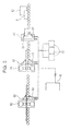
Fig. 3] Fig. 3 is a schematic view illustrating an example of a rolling line including a descaling apparatus for removing scale from a steel sheet according to the present invention. - [
Fig. 4] Fig. 4 is a schematic perspective view illustrating an example of a descaling nozzle according to the present invention. - [
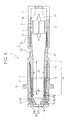
Fig. 5] Fig. 5 is a schematic sectional view taken along a plane of line Y-Y ofFig. 4 in the axial direction. - [
Fig. 6] Fig. 6 is a schematic front view of a discharge section of the nozzle ofFig. 4 . - [
Fig. 7] Fig. 7 illustrates a discharge section of an existing descaling nozzle used in a comparative example. - [
Fig. 8] Fig. 8 illustrates an impact model representing the impact of water droplets on a steel sheet when descaling using sprayed water is performed. - [
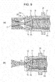
Fig. 9] Fig. 9 illustrates a state of a water flow (main flow) jet,Fig. 9(a) illustrating an example for the descaling nozzle according to the present invention, andFig. 9(b) illustrating an example for an existing descaling nozzle. - Hereinafter, an embodiment of a descaling apparatus for removing scale from a steel sheet including a descaling nozzle according to an aspect of the present invention will be described.
As illustrated inFig. 3 , a rolling line for rolling a steel sheet includes aheating furnace 50 that heats a material to be rolled (steel slab) K, a heating furnacedelivery side descaler 60 that is disposed on the delivery side (HSB) of theheating furnace 50 and that removes scale from the material to be rolled K that has been discharged from theheating furnace 50, arough rolling mill 70 that subsequently performs rough rolling, and afinish rolling mill 80 that subsequently performs finish rolling. - The descaling apparatus according to the present invention is disposed in each section of the rolling line. That is, in the heating furnace
delivery side descaler 60, decalingnozzle attachment adapters 61 for attaching heating furnace delivery side descaling nozzles are disposed above and below the to be rolled material K. Likewise, on the rough rolling entry side (RSB) of therough rolling mill 70, descalingnozzle attachment adapters 62 are disposed above and below the material to be rolled K. On the finish rolling entry side (FSB) of thefinish rolling mill 80, decalingnozzle attachment adapters 63 are disposed above and below the material to be rolled K.A descaling nozzle 1 described below (hereinafter, simply referred to as a "nozzle") is attached to each of the decalingnozzle attachment adapters descaling nozzles 1 attached to the descalingnozzle attachment adapters pumps 30 and anaccumulator 40 through pipes, and can spray high pressure water onto a surface of the material to be rolled K. With this apparatus, the pressure and the amount of sprayed high pressure water can be constantly and stably controlled by using thepumps 30 and theaccumulator 40. - Next, the
nozzle 1 will be described in detail.Fig. 4 is a schematic perspective view of thenozzle 1,Fig. 5 is a schematic sectional view taken along a plane of line Y-Y ofFig. 4 in the axial direction, andFig. 6 is a schematic front view of a discharge section at an end of the nozzle ofFig. 4 .
As illustrated inFigs. 4 to 6 , thenozzle 1 includes acasing 2, anozzle case 11, and anozzle tip 12. These members form a channel (or a nozzle hole) extending in the axial direction of thenozzle 1. - The
casing 2 is substantially cylindrical and has a channel (or a nozzle hole) formed therein. Water can flow into the channel from one end of thecasing 2 on the upstream side of thenozzle 1. Thenozzle case 11 is attached to the other end of thecasing 2. Thenozzle case 11 is substantially cylindrical, and thenozzle tip 12 is attached to an end portion of thenozzle 1. Thenozzle tip 12, from which water is sprayed, is made of a cemented carbide. - In this example, the
casing 2 includes afirst casing 2a, which can be fixed to thenozzle case 11 with a screw thread, and asecond casing 2b, which can be fixed to thefirst casing 2a with a screw thread.
In a peripheral surface and an end surface of the upstream end portion of thesecond casing 2b, a plurality of slits (or inlets) 3 extending in the axial direction are arranged in the circumferential direction at a predetermined pitch. Theslits 3 serve as a filter that allows entry of water while suppressing entry of impurities. A flow regulation unit (or a flow regulator or a stabilizer) 4 is disposed in a channel in thesecond casing 2b. - The
flow regulation unit 4, which guides water from theslits 3 to nozzle holes, includes a plurality of flow regulation plates (flow regulation blades) 5 extending radially from a core member, and a pair of pointed conical portions (respectively tapered upstream and downstream) 6a and 6b, which are formed on the upstream side and on the downstream side of the core member so as to be coaxial with each other and so that the end portions thereof respectively point upstream and downstream. Thecasing 2, which serves as a filter and includes the flow regulation unit, may be called a filter unit or a flow regulation casing.
Theflow regulation plates 5 of theflow regulation unit 4 are in contact with an inner wall of thesecond casing 2b. Movement of theflow regulation unit 4 in the downstream direction is restricted by fixing means (for example, engaging, welding, or adhesion). - The channel in the
casing 2 includes a cylindrical channel P1, an inclined channel (annular inclined channel) P2, and a cylindrical channel P3. The cylindrical channel P1 extends from an upstream end (inlet) of thesecond casing 2b to a downstream end of theflow regulation unit 4 and has a substantially constant inside diameter (which is the same as the inside diameter of the upstream end portion of thecasing 2b). The inclined channel P2 extends downstream from the downstream end of theflow regulation unit 4 to a middle portion of thefirst casing 2a and tapers with a gentle inclination. The cylindrical channel P3 extends downstream from a downstream end of the inclined channel and has a substantially constant inside diameter (which is the same as the inside diameter of a downstream end portion of the inclined channel P2). In this example, the taper angle of an inclined wall (taper portion) of the inclined channel (annular inclined channel) P2 is, for example, in the range of 5 to 10°. - The
nozzle tip 12, which is made of a cemented carbide, and a bushing (or an annular side wall) 17 are attached to the inside of thenozzle case 11 so as to be arranged upstream from the end of thenozzle 1. In thebushing 17, a channel having an inside diameter substantially the same as that of the downstream end of thefirst casing 2a is formed. An engagement steppedportion 13 prevents thenozzle tip 12 from being extracted toward the end portion. - In the
nozzle tip 12, which corresponds to a discharge section at an end of thenozzle 1, includes alarge diameter portion 18 that forms a cylindrical channel, ataper portion 16 that is continuous with thelarge diameter portion 18, and anelliptical discharge hole 15 that is continuous with the outlet side of thetaper portion 16. In an end surface of thenozzle tip 12, acurved groove 14 having a U-shaped cross section is formed so as to extend in the radial direction. As illustrated inFig. 6 , in a concavely curved surface of thecurved groove 14, adischarge hole 15 having an elliptical shape is formed so as to be continuous with the outlet side. The bottom surface of thecurved groove 14 may be a curved bottom surface whose end portions rise from thedischarge hole 15, which is the bottommost portion, in an extension direction (or the radial direction). - The
nozzle 1 has two branch holes (branch flow orifices) 19 that are disposed between thenozzle tip 12 and thenozzle case 11 and that are connected to thelarge diameter portion 18, which forms a cylindrical channel. Each of the branch holes 19 has an arc-shape extending along the circumferential direction of the nozzle tip 12 (in this case, the center of the arc is on the axis). Each of the branch holes 19 discharges a part of water flow in the nozzle so that cavitation C occurs at the boundary between the part of water flow discharged frombranch hole 19 and water flow that is discharged from thedischarge hole 15 in the nozzle tip 12 (seeFig. 9(a) ). Because the branch holes 19 have arc shapes extending in the circumferential direction of thenozzle tip 12, each of the branch holes 19 discharges water flow so that the water flow surrounds water flow that is discharged from thedischarge hole 15. - Thus, a nozzle channel (nozzle hole), which extends in the axial direction of the
nozzle 1, includes a conical channel P5, branch channels P6, a cylindrical channel P4, and the cylindrical large-diameter channels (channels extending from the upstream end of the cylindrical channel P4 to the upstream end of the flow regulation unit 4) P3 to P1. The conical channel P5 includes the taper portion (or a conical inclined wall) 16 extending upstream from thedischarge hole 15 in the axial direction with linearly increasing diameter. The branch channels P6 are formed between thenozzle tip 12 and thenozzle case 11 and include the branch holes 19. The cylindrical channel P4 is formed by the inner periphery of thebushing 17 and extends upstream from the upstream end of thetaper portion 16 in the axial direction with a substantially uniform inside diameter. The cylindrical large-diameter channels P3 to P1 extend from the upstream end of the cylindrical channel P4 with a substantially uniform inside diameter. Alarge diameter portion 18 includes a channel extending from the upstream end of thetaper portion 16 with a substantially uniform inside diameter (in this example, the cylindrical channels P3 and P4, which extend from the upstream end of thetaper portion 16 to the downstream end of the gently inclined channel P2) - The
discharge hole 15 has an elliptical shape whose ratio of the major axis D3 to the minor axis D2 is in the range of about 1.5 to 1.8. Regarding the relationship between thedischarge hole 15 and thelarge diameter portion 18, in order to reduce the size of the nozzle, the ratio (D1/D2) of the inside diameter D1 of the large diameter portion 18 (the cylindrical channels P3 and P4, or the downstream end of the inclined channel P2 extending downward from the flow regulation unit) to the minor axis D2 of thedischarge hole 15 is set in the range of about 4.5 to 6.9. In order to increase the impact force even if sprayed water has a low pressure and/or a low flow rate, the angle (taper angle) θ of thetaper portion 16 is set in the range of about 45 to 55°. - An attachment portion such as a flange portion (or flange) 24 for attaching the
nozzle 1 to a conduit (not shown) using an adapter (not shown) can be formed at an appropriate position on thenozzle case 11 or the casing 2 (in this example, the nozzle case 2). Apositioning protrusion 25 for positioning thenozzle case 11 relative to a conduit may be formed on thenozzle case 11 so that the positioning accuracy can be increased and water can be sprayed in a flat shape or a strip-like shape in a predetermined direction. - Next, the effects and advantages of the descaling apparatus for removing scale from a steel sheet described above, the
descaling nozzle 1 attached to the descaling apparatus, and a descaling method for removing scale from a steel sheet using thenozzle 1 will be described.
Thenozzle 1 is attached to each of the descalingnozzle attachment adapters nozzle 1 includes thetaper portion 16, which is continuous with thelarge diameter portion 18 that forms a cylindrical channel, and thedischarge hole 15. Thedischarge hole 15 is continuous with the outlet side of thetaper portion 16. Moreover, the branch holes 19 is disposed between thenozzle tip 12 and thenozzle case 11 so as to be connected to thelarge diameter portion 18, which forms the cylindrical channel. The branch holes 19 discharge a part of water flow in the nozzle so that cavitation occurs at the boundary between the part of water flow discharged from the branch holes 19 and water flow that is discharged from thedischarge hole 15 in thenozzle tip 12. Thus, the nozzle can cause cavitation at the boundary between the part of water flow discharged from the branch holes and the water flow (main flow) discharged from the orifice of the nozzle. As a result, the descaling performance can be significantly improved as compared with existing nozzles. Accordingly, with the descaling apparatus, thedescaling nozzle 1 attached to the descaling apparatus, and the descaling method for removing scale from a steel sheet using thenozzle 1, performance and efficiency in descaling can be significantly improved. - Hereinafter, an example in which the
nozzle 1 according to the embodiment was used in a descaling apparatus in an actual rolling line for rolling a material to be rolled K will be described. Steel materials used in the example had a standard width of 1.2 m and a standard thickness of 220 mm on the delivery side of theheating furnace 50, a standard thickness in the range of 220 to 70 mm on the rough rolling entry side (RSB) 62, and a standard thickness in the range of 60 to 40 mm on the finish rolling entry side (FSB) 63. Table 1 below shows the results of a comparative experiment in which comparison with an existing type of nozzle was performed (seeFig. 7 ). In this example, the ratio of the amount of water flow in the nozzle that is introduced into the branch holes to the amount of entire water flow in the nozzle was adjusted so as to be in the range of 0% or greater to less than or equal to 50% in accordance with the spraying pressure PO [Pa], the descaling flow rate [1/min], and the spraying distance H[m]. - As an evaluation method, a descaling performance evaluation model that had been proposed (see Japanese Patent No.
3129967 Fig. 8 illustrates an impact model representing the impact of water droplets on a steel sheet when descaling using sprayed water is performed. The total impact force (F) and the unit impact force (S) inFig. 8 can be represented by the following equations:

where F is the total impact force [N] of sprayed water at a surface of a steel sheet, S is the unit impact force [Pa] of sprayed water at the surface of the steel sheet, P0 is the spraying pressure [Pa], a is the orifice area [m2], C is the sonic speed [m/s], d is the droplet diameter of a water droplet [m], α is a coefficient, and t is the time during which a shock wave travels across the droplet [s]. -
[Table 1] Evaluation Indices Values for Comparative Example Values for Invention Example Descaling Performance (1) HSB 1.50 MPa 2.25 MPa (1.5 times higher) (Unit Impact Force S) (2) RSB 0.26 MPa 0.34 MPa (1.3 times higher) (3) FSB 0.91 MPa 1.18 MPa (1.3 times higher) Descaling Flow Rate (1) HSB 111 l/min 111 l/min (2) RSB 66 l/min 39 l/min (3) FSB 66 l/min 39 l/min Electric Power Consumption Rate of Descaling Pump 1.0 0.7 Index of Fraction Defective due to Decaling Performance 1.0 less then 0.5 - As shown in this table, in any section of the rolling line, the descaling performance was increased by 1.3 to 1.5 times that of the comparative example, the electric power consumption rate of the
pump 30 was 70%, a possible reduction margin of flow rate due to improvement in the descaling performance was 30%, and the fraction defective due to the descaling performance was less than 50% of the comparative example. Therefore, with thedescaling nozzle 1, the performance and efficiency in descaling was significantly improved. - According to the results of a comparative experiment using an existing type (see
Figs. 7 and9(b) ), it was confirmed that a sufficient effect can be obtained by adjusting the ratio of the amount of water flow that is introduced into the branch holes 19 to the amount of the entire water flow in the nozzle so as to be in the range of 0% or greater to less than an equal to 50% in accordance with the spraying pressure P0 [Pa], the descaling flow rate [1/min], and the spraying distance H [m].
A descaling nozzle for removing scale from a steel sheet, a descaling apparatus for removing scale from a steel sheet, and descaling method for removing scale from a steel sheet according to the present invention are not limited to the embodiments described above. The embodiments can be modified in various ways within the spirit and scope of the present invention. -
- 1
- (descaling) nozzle
- 2
- casing
- 4
- flow regulation unit
- 11
- nozzle case
- 12
- nozzle tip
- 14
- curved groove
- 15
- discharge hole (main flow orifice)
- 16
- taper portion (or conical inclined wall)
- 17
- bushing (or annular side wall)
- 18
- large diameter portion
- 19
- branch hole (branch flow orifice)
- 20
- discharge section
- 30
- pump
- 40
- accumulator
- 50
- heating furnace
- 60
- heating furnace delivery side descaler
- 61, 62, 63
- descaling nozzle attachment adapter
- 70
- rough rolling mill
- 80
- finish rolling mill
- K
- material to be rolled (steel slab)
- P1
- cylindrical channel
- P2
- inclined channel
- P3
- cylindrical channel
- P4
- cylindrical channel
- P5
- cylindrical channel
- P6
- branch channel
Claims (5)
- A descaling nozzle for removing scale from a steel sheet by spraying water onto a surface of the steel sheet and using impact of the sprayed water,
wherein a discharge section at an end of the nozzle includes a main flow orifice and a branch flow orifice that are connected to a large diameter portion that forms a cylindrical channel, and wherein the branch flow orifice discharges a part of water flow in the large diameter portion so that cavitation occurs at a boundary between the part of water flow discharged from the branch orifice and water flow that is discharged from the main flow orifice. - The descaling nozzle according to Claim 1, wherein the branch flow orifice discharges water flow so that the water flow surrounds an outer periphery of water flow that is discharged from the main flow orifice.
- The descaling nozzle according to Claim 1 or 2, wherein the ratio of an amount of water flow in the large diameter portion that is introduced into the branch flow orifice to an amount of entire water flow in the large diameter portion is greater than 0% and less than or equal to 50%.
- A descaling apparatus for removing scale from a steel sheet, the descaling apparatus comprising a plurality of descaling nozzles disposed above and below the steel sheet that is a material to be roled in a rolling process, the descaling apparatus removing scale from a surface of the material to be rolled by spraying high pressure water from the descaling nozzles onto the surface of the material to be rolled,
wherein each of the descaling nozzles is the descaling nozzle according to any one of Claims 1 to 3. - A method for removing scale from a steel sheet that is a material to be rolled in a rolling process by spraying high pressure water from a descaling nozzle onto a surface of the material to be rolled,
wherein the descaling nozzle according to any one of Claims 1 to 3 is used as the descaling nozzle, the descaling nozzle is disposed at each of a plurality of positions above and below the rolling material in the rolling process, and high pressure water is sprayed from the descaling nozzles onto the surface of the material to be rolled to remove scale from the surface of the material to be rolled.
Applications Claiming Priority (3)
| Application Number | Priority Date | Filing Date | Title |
|---|---|---|---|
| JP2011013923 | 2011-01-26 | ||
| JP2011266196A JP5834853B2 (en) | 2011-01-26 | 2011-12-05 | Steel plate scale removal nozzle, steel plate scale removal apparatus, and steel plate scale removal method |
| PCT/JP2011/079272 WO2012101932A1 (en) | 2011-01-26 | 2011-12-13 | Nozzle for descaling steel plate, device for descaling steel plate, and method for descaling steel plate |
Publications (3)
| Publication Number | Publication Date |
|---|---|
| EP2669021A1 true EP2669021A1 (en) | 2013-12-04 |
| EP2669021A4 EP2669021A4 (en) | 2016-08-24 |
| EP2669021B1 EP2669021B1 (en) | 2019-03-20 |
Family
ID=46580514
Family Applications (1)
| Application Number | Title | Priority Date | Filing Date |
|---|---|---|---|
| EP11856996.1A Active EP2669021B1 (en) | 2011-01-26 | 2011-12-13 | Nozzle for descaling steel plate, device for descaling steel plate, and method for descaling steel plate |
Country Status (6)
| Country | Link |
|---|---|
| US (1) | US9216446B2 (en) |
| EP (1) | EP2669021B1 (en) |
| JP (1) | JP5834853B2 (en) |
| KR (2) | KR20130111616A (en) |
| CN (1) | CN103402663B (en) |
| WO (1) | WO2012101932A1 (en) |
Families Citing this family (7)
| Publication number | Priority date | Publication date | Assignee | Title |
|---|---|---|---|---|
| JP6941850B2 (en) * | 2016-08-15 | 2021-09-29 | 日本ビニロン株式会社 | Washer nozzle |
| CN110873587B (en) * | 2018-08-29 | 2021-06-22 | 精诚工科汽车系统有限公司 | Nozzle anticollision detection device and automatic bonding equipment |
| CN110744417A (en) * | 2019-10-07 | 2020-02-04 | 浙江谋皮环保科技有限公司 | Steel sheet rust cleaning production line |
| CN110774178B (en) * | 2019-10-30 | 2024-09-17 | 北京电子科技职业学院 | A protection and guiding device for acid-free descaling shot flow |
| US20210387309A1 (en) * | 2020-06-12 | 2021-12-16 | The Boeing Company | Enhanced intensity cavitation nozzles |
| RU2764450C1 (en) * | 2020-11-20 | 2022-01-17 | Публичное акционерное общество "Северсталь" (ПАО "Северсталь") | High-pressure injector and method for manufacturing parts therefor |
| US12466028B2 (en) * | 2022-07-01 | 2025-11-11 | The Boeing Company | Damage tolerant cavitation nozzle |
Family Cites Families (26)
| Publication number | Priority date | Publication date | Assignee | Title |
|---|---|---|---|---|
| BE533883A (en) * | 1953-12-05 | |||
| US4095747A (en) * | 1976-05-17 | 1978-06-20 | Specialty Manufacturing Company | High pressure coaxial flow nozzles |
| JPS6015684B2 (en) | 1977-05-13 | 1985-04-20 | 新日本製鐵株式会社 | Method for manufacturing hot rolled steel materials |
| JPS581167B2 (en) | 1978-03-03 | 1983-01-10 | 川崎製鉄株式会社 | Method for producing silicon-containing steel material with excellent surface properties |
| US4185706A (en) * | 1978-11-17 | 1980-01-29 | Smith International, Inc. | Rock bit with cavitating jet nozzles |
| JPS581167A (en) | 1981-06-26 | 1983-01-06 | Canon Inc | Reciprocating driving device |
| JPS6015684A (en) | 1983-07-08 | 1985-01-26 | セイコーエプソン株式会社 | Manufacture of liquid crystal display body |
| SU1286308A1 (en) * | 1985-02-11 | 1987-01-30 | Государственный Проектный Институт "Ярославский Промстройпроект" | Apparatus for cleaning inner surface of pipelines |
| GB8726688D0 (en) * | 1987-11-13 | 1987-12-16 | Wakefield A W | Jetting nozzle |
| JPH0688062B2 (en) | 1988-03-31 | 1994-11-09 | 日新製鋼株式会社 | How to prevent scale defects in hot-rolled steel sheets |
| DE4328303C2 (en) * | 1992-12-23 | 1997-02-13 | Juergen Gaydoul | Device for descaling hot rolled material |
| JPH08257998A (en) * | 1995-03-23 | 1996-10-08 | Ebara Corp | Cavitation jet nozzle |
| JP3129967B2 (en) | 1995-06-30 | 2001-01-31 | 川崎製鉄株式会社 | How to remove scale from hot rolled steel sheet |
| JP3795240B2 (en) * | 1998-12-08 | 2006-07-12 | バブコック日立株式会社 | Water jet nozzle |
| JP2003062492A (en) * | 2001-08-23 | 2003-03-04 | Japan Science & Technology Corp | Method for surface treatment and cleaning of machine parts and the like, and their devices |
| RU2222464C2 (en) * | 2002-04-25 | 2004-01-27 | Общество с ограниченной ответственностью "РуссАква" | Cavitation injector |
| JP4084295B2 (en) | 2002-12-25 | 2008-04-30 | 株式会社共立合金製作所 | Descaling nozzle |
| KR100606629B1 (en) * | 2002-12-25 | 2006-07-31 | 가부시키가이샤 교리쯔 고우낀 세이사꾸쇼 | Descaling Nozzles and Carbide Nozzle Tips |
| JP4854935B2 (en) * | 2003-06-25 | 2012-01-18 | Jfeスチール株式会社 | Steel plate scale remover |
| WO2006043911A1 (en) * | 2004-10-18 | 2006-04-27 | Zakharchenko Sergiy Gennadevic | Cavitation nozzle |
| WO2006084085A1 (en) * | 2005-02-04 | 2006-08-10 | Ismailov Murad M | Liquid spray system and nozzle with improved spray generation |
| US7077724B1 (en) * | 2005-06-06 | 2006-07-18 | The Material Works, Ltd. | Sheet metal scale removing water jet process |
| JP4525475B2 (en) * | 2005-06-07 | 2010-08-18 | 株式会社デンソー | Surface processing method |
| JP5103770B2 (en) | 2006-03-28 | 2012-12-19 | Jfeスチール株式会社 | Compound nozzle and method of treating steel surface |
| JP2011131275A (en) | 2009-11-25 | 2011-07-07 | Kyoritsu Gokin Co Ltd | Descaling nozzle device and descaling method |
| CA2742060C (en) * | 2011-05-31 | 2013-09-10 | Vln Advanced Technologies Inc. | Reverse-flow nozzle for generating cavitating or pulsed jets |
-
2011
- 2011-12-05 JP JP2011266196A patent/JP5834853B2/en active Active
- 2011-12-13 US US13/977,324 patent/US9216446B2/en active Active
- 2011-12-13 CN CN201180066196.9A patent/CN103402663B/en not_active Expired - Fee Related
- 2011-12-13 WO PCT/JP2011/079272 patent/WO2012101932A1/en not_active Ceased
- 2011-12-13 KR KR1020137019589A patent/KR20130111616A/en not_active Ceased
- 2011-12-13 EP EP11856996.1A patent/EP2669021B1/en active Active
- 2011-12-13 KR KR1020157025715A patent/KR101644003B1/en not_active Expired - Fee Related
Non-Patent Citations (1)
| Title |
|---|
| See references of WO2012101932A1 * |
Also Published As
| Publication number | Publication date |
|---|---|
| WO2012101932A1 (en) | 2012-08-02 |
| US20130298626A1 (en) | 2013-11-14 |
| EP2669021B1 (en) | 2019-03-20 |
| JP5834853B2 (en) | 2015-12-24 |
| JP2012166262A (en) | 2012-09-06 |
| KR20150113212A (en) | 2015-10-07 |
| KR20130111616A (en) | 2013-10-10 |
| EP2669021A4 (en) | 2016-08-24 |
| US9216446B2 (en) | 2015-12-22 |
| CN103402663A (en) | 2013-11-20 |
| KR101644003B1 (en) | 2016-07-29 |
| CN103402663B (en) | 2016-10-19 |
Similar Documents
| Publication | Publication Date | Title |
|---|---|---|
| EP2669021B1 (en) | Nozzle for descaling steel plate, device for descaling steel plate, and method for descaling steel plate | |
| EP2653243B1 (en) | Nozzle for removing scale of steel plate, scale removing device for steel plate, and method for removing scale of steel plate | |
| EP1575719B2 (en) | Descaling nozzle | |
| JP5851136B2 (en) | Cooling device and cooling method for metal tube after heating | |
| KR100973692B1 (en) | Hot Rolling Equipment and Hot Rolling Method of Steel Sheet | |
| JP4854935B2 (en) | Steel plate scale remover | |
| JP5857653B2 (en) | Descaling device | |
| EP2492026B1 (en) | Hot rolling high-pressure fluid descaling method and descaling apparatus | |
| JP5469366B2 (en) | spray nozzle | |
| EP3195946B1 (en) | Thick steel plate manufacturing method | |
| CN104169014B (en) | Descale system | |
| EP3187275B1 (en) | Thick steel plate manufacturing method | |
| JP2000271615A (en) | Work roll cleaning method and apparatus | |
| US20250303472A1 (en) | Suction unit for an exhaust device and additive manufacturing device comprising an exhaust device | |
| CN109702162A (en) | A continuous casting machine and its slab surface cleaning device | |
| EP2298462B1 (en) | Production method of hot rolled steel sheet | |
| JP2014176884A (en) | Descaling nozzle, descaling device and descaling method |
Legal Events
| Date | Code | Title | Description |
|---|---|---|---|
| PUAI | Public reference made under article 153(3) epc to a published international application that has entered the european phase |
Free format text: ORIGINAL CODE: 0009012 |
|
| 17P | Request for examination filed |
Effective date: 20130724 |
|
| AK | Designated contracting states |
Kind code of ref document: A1 Designated state(s): AL AT BE BG CH CY CZ DE DK EE ES FI FR GB GR HR HU IE IS IT LI LT LU LV MC MK MT NL NO PL PT RO RS SE SI SK SM TR |
|
| DAX | Request for extension of the european patent (deleted) | ||
| RA4 | Supplementary search report drawn up and despatched (corrected) |
Effective date: 20160721 |
|
| RIC1 | Information provided on ipc code assigned before grant |
Ipc: B05B 1/02 20060101ALI20160715BHEP Ipc: B21B 45/08 20060101AFI20160715BHEP Ipc: B08B 3/02 20060101ALI20160715BHEP |
|
| REG | Reference to a national code |
Ref country code: DE Ref legal event code: R079 Ref document number: 602011057428 Country of ref document: DE Free format text: PREVIOUS MAIN CLASS: B21B0045080000 Ipc: B05B0001040000 |
|
| GRAP | Despatch of communication of intention to grant a patent |
Free format text: ORIGINAL CODE: EPIDOSNIGR1 |
|
| STAA | Information on the status of an ep patent application or granted ep patent |
Free format text: STATUS: GRANT OF PATENT IS INTENDED |
|
| RIC1 | Information provided on ipc code assigned before grant |
Ipc: B05B 1/04 20060101AFI20180911BHEP Ipc: B05B 1/14 20060101ALI20180911BHEP Ipc: B05B 15/40 20180101ALN20180911BHEP Ipc: B05B 15/18 20180101ALN20180911BHEP Ipc: B21B 45/08 20060101ALN20180911BHEP Ipc: B05B 13/02 20060101ALN20180911BHEP |
|
| RIC1 | Information provided on ipc code assigned before grant |
Ipc: B05B 1/14 20060101ALI20180925BHEP Ipc: B21B 45/08 20060101ALN20180925BHEP Ipc: B05B 1/04 20060101AFI20180925BHEP Ipc: B05B 15/18 20180101ALN20180925BHEP Ipc: B05B 13/02 20060101ALN20180925BHEP Ipc: B05B 15/40 20180101ALN20180925BHEP |
|
| INTG | Intention to grant announced |
Effective date: 20181016 |
|
| GRAS | Grant fee paid |
Free format text: ORIGINAL CODE: EPIDOSNIGR3 |
|
| RIC1 | Information provided on ipc code assigned before grant |
Ipc: B05B 1/04 20060101AFI20180925BHEP Ipc: B05B 15/18 20180101ALN20180925BHEP Ipc: B05B 1/14 20060101ALI20180925BHEP Ipc: B21B 45/08 20060101ALN20180925BHEP Ipc: B05B 15/40 20180101ALN20180925BHEP Ipc: B05B 13/02 20060101ALN20180925BHEP |
|
| GRAA | (expected) grant |
Free format text: ORIGINAL CODE: 0009210 |
|
| STAA | Information on the status of an ep patent application or granted ep patent |
Free format text: STATUS: THE PATENT HAS BEEN GRANTED |
|
| AK | Designated contracting states |
Kind code of ref document: B1 Designated state(s): AL AT BE BG CH CY CZ DE DK EE ES FI FR GB GR HR HU IE IS IT LI LT LU LV MC MK MT NL NO PL PT RO RS SE SI SK SM TR |
|
| REG | Reference to a national code |
Ref country code: GB Ref legal event code: FG4D |
|
| REG | Reference to a national code |
Ref country code: CH Ref legal event code: EP |
|
| REG | Reference to a national code |
Ref country code: DE Ref legal event code: R096 Ref document number: 602011057428 Country of ref document: DE |
|
| REG | Reference to a national code |
Ref country code: AT Ref legal event code: REF Ref document number: 1110012 Country of ref document: AT Kind code of ref document: T Effective date: 20190415 |
|
| REG | Reference to a national code |
Ref country code: IE Ref legal event code: FG4D |
|
| REG | Reference to a national code |
Ref country code: NL Ref legal event code: MP Effective date: 20190320 |
|
| PG25 | Lapsed in a contracting state [announced via postgrant information from national office to epo] |
Ref country code: NO Free format text: LAPSE BECAUSE OF FAILURE TO SUBMIT A TRANSLATION OF THE DESCRIPTION OR TO PAY THE FEE WITHIN THE PRESCRIBED TIME-LIMIT Effective date: 20190620 Ref country code: LT Free format text: LAPSE BECAUSE OF FAILURE TO SUBMIT A TRANSLATION OF THE DESCRIPTION OR TO PAY THE FEE WITHIN THE PRESCRIBED TIME-LIMIT Effective date: 20190320 Ref country code: SE Free format text: LAPSE BECAUSE OF FAILURE TO SUBMIT A TRANSLATION OF THE DESCRIPTION OR TO PAY THE FEE WITHIN THE PRESCRIBED TIME-LIMIT Effective date: 20190320 Ref country code: FI Free format text: LAPSE BECAUSE OF FAILURE TO SUBMIT A TRANSLATION OF THE DESCRIPTION OR TO PAY THE FEE WITHIN THE PRESCRIBED TIME-LIMIT Effective date: 20190320 |
|
| REG | Reference to a national code |
Ref country code: LT Ref legal event code: MG4D |
|
| PG25 | Lapsed in a contracting state [announced via postgrant information from national office to epo] |
Ref country code: RS Free format text: LAPSE BECAUSE OF FAILURE TO SUBMIT A TRANSLATION OF THE DESCRIPTION OR TO PAY THE FEE WITHIN THE PRESCRIBED TIME-LIMIT Effective date: 20190320 Ref country code: NL Free format text: LAPSE BECAUSE OF FAILURE TO SUBMIT A TRANSLATION OF THE DESCRIPTION OR TO PAY THE FEE WITHIN THE PRESCRIBED TIME-LIMIT Effective date: 20190320 Ref country code: BG Free format text: LAPSE BECAUSE OF FAILURE TO SUBMIT A TRANSLATION OF THE DESCRIPTION OR TO PAY THE FEE WITHIN THE PRESCRIBED TIME-LIMIT Effective date: 20190620 Ref country code: LV Free format text: LAPSE BECAUSE OF FAILURE TO SUBMIT A TRANSLATION OF THE DESCRIPTION OR TO PAY THE FEE WITHIN THE PRESCRIBED TIME-LIMIT Effective date: 20190320 Ref country code: GR Free format text: LAPSE BECAUSE OF FAILURE TO SUBMIT A TRANSLATION OF THE DESCRIPTION OR TO PAY THE FEE WITHIN THE PRESCRIBED TIME-LIMIT Effective date: 20190621 Ref country code: HR Free format text: LAPSE BECAUSE OF FAILURE TO SUBMIT A TRANSLATION OF THE DESCRIPTION OR TO PAY THE FEE WITHIN THE PRESCRIBED TIME-LIMIT Effective date: 20190320 |
|
| REG | Reference to a national code |
Ref country code: AT Ref legal event code: MK05 Ref document number: 1110012 Country of ref document: AT Kind code of ref document: T Effective date: 20190320 |
|
| PG25 | Lapsed in a contracting state [announced via postgrant information from national office to epo] |
Ref country code: EE Free format text: LAPSE BECAUSE OF FAILURE TO SUBMIT A TRANSLATION OF THE DESCRIPTION OR TO PAY THE FEE WITHIN THE PRESCRIBED TIME-LIMIT Effective date: 20190320 Ref country code: SK Free format text: LAPSE BECAUSE OF FAILURE TO SUBMIT A TRANSLATION OF THE DESCRIPTION OR TO PAY THE FEE WITHIN THE PRESCRIBED TIME-LIMIT Effective date: 20190320 Ref country code: AL Free format text: LAPSE BECAUSE OF FAILURE TO SUBMIT A TRANSLATION OF THE DESCRIPTION OR TO PAY THE FEE WITHIN THE PRESCRIBED TIME-LIMIT Effective date: 20190320 Ref country code: PT Free format text: LAPSE BECAUSE OF FAILURE TO SUBMIT A TRANSLATION OF THE DESCRIPTION OR TO PAY THE FEE WITHIN THE PRESCRIBED TIME-LIMIT Effective date: 20190720 Ref country code: ES Free format text: LAPSE BECAUSE OF FAILURE TO SUBMIT A TRANSLATION OF THE DESCRIPTION OR TO PAY THE FEE WITHIN THE PRESCRIBED TIME-LIMIT Effective date: 20190320 Ref country code: CZ Free format text: LAPSE BECAUSE OF FAILURE TO SUBMIT A TRANSLATION OF THE DESCRIPTION OR TO PAY THE FEE WITHIN THE PRESCRIBED TIME-LIMIT Effective date: 20190320 Ref country code: RO Free format text: LAPSE BECAUSE OF FAILURE TO SUBMIT A TRANSLATION OF THE DESCRIPTION OR TO PAY THE FEE WITHIN THE PRESCRIBED TIME-LIMIT Effective date: 20190320 |
|
| PG25 | Lapsed in a contracting state [announced via postgrant information from national office to epo] |
Ref country code: SM Free format text: LAPSE BECAUSE OF FAILURE TO SUBMIT A TRANSLATION OF THE DESCRIPTION OR TO PAY THE FEE WITHIN THE PRESCRIBED TIME-LIMIT Effective date: 20190320 Ref country code: PL Free format text: LAPSE BECAUSE OF FAILURE TO SUBMIT A TRANSLATION OF THE DESCRIPTION OR TO PAY THE FEE WITHIN THE PRESCRIBED TIME-LIMIT Effective date: 20190320 |
|
| PG25 | Lapsed in a contracting state [announced via postgrant information from national office to epo] |
Ref country code: AT Free format text: LAPSE BECAUSE OF FAILURE TO SUBMIT A TRANSLATION OF THE DESCRIPTION OR TO PAY THE FEE WITHIN THE PRESCRIBED TIME-LIMIT Effective date: 20190320 Ref country code: IS Free format text: LAPSE BECAUSE OF FAILURE TO SUBMIT A TRANSLATION OF THE DESCRIPTION OR TO PAY THE FEE WITHIN THE PRESCRIBED TIME-LIMIT Effective date: 20190720 |
|
| REG | Reference to a national code |
Ref country code: DE Ref legal event code: R097 Ref document number: 602011057428 Country of ref document: DE |
|
| PLBE | No opposition filed within time limit |
Free format text: ORIGINAL CODE: 0009261 |
|
| STAA | Information on the status of an ep patent application or granted ep patent |
Free format text: STATUS: NO OPPOSITION FILED WITHIN TIME LIMIT |
|
| PG25 | Lapsed in a contracting state [announced via postgrant information from national office to epo] |
Ref country code: DK Free format text: LAPSE BECAUSE OF FAILURE TO SUBMIT A TRANSLATION OF THE DESCRIPTION OR TO PAY THE FEE WITHIN THE PRESCRIBED TIME-LIMIT Effective date: 20190320 |
|
| 26N | No opposition filed |
Effective date: 20200102 |
|
| PG25 | Lapsed in a contracting state [announced via postgrant information from national office to epo] |
Ref country code: SI Free format text: LAPSE BECAUSE OF FAILURE TO SUBMIT A TRANSLATION OF THE DESCRIPTION OR TO PAY THE FEE WITHIN THE PRESCRIBED TIME-LIMIT Effective date: 20190320 |
|
| PG25 | Lapsed in a contracting state [announced via postgrant information from national office to epo] |
Ref country code: TR Free format text: LAPSE BECAUSE OF FAILURE TO SUBMIT A TRANSLATION OF THE DESCRIPTION OR TO PAY THE FEE WITHIN THE PRESCRIBED TIME-LIMIT Effective date: 20190320 |
|
| REG | Reference to a national code |
Ref country code: CH Ref legal event code: PL |
|
| REG | Reference to a national code |
Ref country code: BE Ref legal event code: MM Effective date: 20191231 |
|
| PG25 | Lapsed in a contracting state [announced via postgrant information from national office to epo] |
Ref country code: MC Free format text: LAPSE BECAUSE OF FAILURE TO SUBMIT A TRANSLATION OF THE DESCRIPTION OR TO PAY THE FEE WITHIN THE PRESCRIBED TIME-LIMIT Effective date: 20190320 |
|
| PG25 | Lapsed in a contracting state [announced via postgrant information from national office to epo] |
Ref country code: LU Free format text: LAPSE BECAUSE OF NON-PAYMENT OF DUE FEES Effective date: 20191213 Ref country code: IE Free format text: LAPSE BECAUSE OF NON-PAYMENT OF DUE FEES Effective date: 20191213 |
|
| PG25 | Lapsed in a contracting state [announced via postgrant information from national office to epo] |
Ref country code: LI Free format text: LAPSE BECAUSE OF NON-PAYMENT OF DUE FEES Effective date: 20191231 Ref country code: CH Free format text: LAPSE BECAUSE OF NON-PAYMENT OF DUE FEES Effective date: 20191231 Ref country code: BE Free format text: LAPSE BECAUSE OF NON-PAYMENT OF DUE FEES Effective date: 20191231 |
|
| PG25 | Lapsed in a contracting state [announced via postgrant information from national office to epo] |
Ref country code: CY Free format text: LAPSE BECAUSE OF FAILURE TO SUBMIT A TRANSLATION OF THE DESCRIPTION OR TO PAY THE FEE WITHIN THE PRESCRIBED TIME-LIMIT Effective date: 20190320 |
|
| PG25 | Lapsed in a contracting state [announced via postgrant information from national office to epo] |
Ref country code: MT Free format text: LAPSE BECAUSE OF FAILURE TO SUBMIT A TRANSLATION OF THE DESCRIPTION OR TO PAY THE FEE WITHIN THE PRESCRIBED TIME-LIMIT Effective date: 20190320 Ref country code: HU Free format text: LAPSE BECAUSE OF FAILURE TO SUBMIT A TRANSLATION OF THE DESCRIPTION OR TO PAY THE FEE WITHIN THE PRESCRIBED TIME-LIMIT; INVALID AB INITIO Effective date: 20111213 |
|
| PG25 | Lapsed in a contracting state [announced via postgrant information from national office to epo] |
Ref country code: MK Free format text: LAPSE BECAUSE OF FAILURE TO SUBMIT A TRANSLATION OF THE DESCRIPTION OR TO PAY THE FEE WITHIN THE PRESCRIBED TIME-LIMIT Effective date: 20190320 |
|
| PGFP | Annual fee paid to national office [announced via postgrant information from national office to epo] |
Ref country code: DE Payment date: 20251028 Year of fee payment: 15 |
|
| PGFP | Annual fee paid to national office [announced via postgrant information from national office to epo] |
Ref country code: GB Payment date: 20251030 Year of fee payment: 15 |
|
| PGFP | Annual fee paid to national office [announced via postgrant information from national office to epo] |
Ref country code: IT Payment date: 20251121 Year of fee payment: 15 |
|
| PGFP | Annual fee paid to national office [announced via postgrant information from national office to epo] |
Ref country code: FR Payment date: 20251110 Year of fee payment: 15 |