EP2668930A1 - Lateral entry insert for cup trial - Google Patents
Lateral entry insert for cup trial Download PDFInfo
- Publication number
- EP2668930A1 EP2668930A1 EP13169019.0A EP13169019A EP2668930A1 EP 2668930 A1 EP2668930 A1 EP 2668930A1 EP 13169019 A EP13169019 A EP 13169019A EP 2668930 A1 EP2668930 A1 EP 2668930A1
- Authority
- EP
- European Patent Office
- Prior art keywords
- trial
- insert
- cup
- assembly
- trial insert
- Prior art date
- Legal status (The legal status is an assumption and is not a legal conclusion. Google has not performed a legal analysis and makes no representation as to the accuracy of the status listed.)
- Granted
Links
Images


Classifications
-
- A—HUMAN NECESSITIES
- A61—MEDICAL OR VETERINARY SCIENCE; HYGIENE
- A61F—FILTERS IMPLANTABLE INTO BLOOD VESSELS; PROSTHESES; DEVICES PROVIDING PATENCY TO, OR PREVENTING COLLAPSING OF, TUBULAR STRUCTURES OF THE BODY, e.g. STENTS; ORTHOPAEDIC, NURSING OR CONTRACEPTIVE DEVICES; FOMENTATION; TREATMENT OR PROTECTION OF EYES OR EARS; BANDAGES, DRESSINGS OR ABSORBENT PADS; FIRST-AID KITS
- A61F2/00—Filters implantable into blood vessels; Prostheses, i.e. artificial substitutes or replacements for parts of the body; Appliances for connecting them with the body; Devices providing patency to, or preventing collapsing of, tubular structures of the body, e.g. stents
- A61F2/02—Prostheses implantable into the body
- A61F2/30—Joints
- A61F2/40—Joints for shoulders
- A61F2/4014—Humeral heads or necks; Connections of endoprosthetic heads or necks to endoprosthetic humeral shafts
-
- A—HUMAN NECESSITIES
- A61—MEDICAL OR VETERINARY SCIENCE; HYGIENE
- A61F—FILTERS IMPLANTABLE INTO BLOOD VESSELS; PROSTHESES; DEVICES PROVIDING PATENCY TO, OR PREVENTING COLLAPSING OF, TUBULAR STRUCTURES OF THE BODY, e.g. STENTS; ORTHOPAEDIC, NURSING OR CONTRACEPTIVE DEVICES; FOMENTATION; TREATMENT OR PROTECTION OF EYES OR EARS; BANDAGES, DRESSINGS OR ABSORBENT PADS; FIRST-AID KITS
- A61F2/00—Filters implantable into blood vessels; Prostheses, i.e. artificial substitutes or replacements for parts of the body; Appliances for connecting them with the body; Devices providing patency to, or preventing collapsing of, tubular structures of the body, e.g. stents
- A61F2/02—Prostheses implantable into the body
- A61F2/30—Joints
- A61F2/46—Special tools or methods for implanting or extracting artificial joints, accessories, bone grafts or substitutes, or particular adaptations therefor
- A61F2/4684—Trial or dummy prostheses
-
- A—HUMAN NECESSITIES
- A61—MEDICAL OR VETERINARY SCIENCE; HYGIENE
- A61F—FILTERS IMPLANTABLE INTO BLOOD VESSELS; PROSTHESES; DEVICES PROVIDING PATENCY TO, OR PREVENTING COLLAPSING OF, TUBULAR STRUCTURES OF THE BODY, e.g. STENTS; ORTHOPAEDIC, NURSING OR CONTRACEPTIVE DEVICES; FOMENTATION; TREATMENT OR PROTECTION OF EYES OR EARS; BANDAGES, DRESSINGS OR ABSORBENT PADS; FIRST-AID KITS
- A61F2/00—Filters implantable into blood vessels; Prostheses, i.e. artificial substitutes or replacements for parts of the body; Appliances for connecting them with the body; Devices providing patency to, or preventing collapsing of, tubular structures of the body, e.g. stents
- A61F2/02—Prostheses implantable into the body
- A61F2/30—Joints
- A61F2/40—Joints for shoulders
- A61F2/4014—Humeral heads or necks; Connections of endoprosthetic heads or necks to endoprosthetic humeral shafts
- A61F2002/4018—Heads or epiphyseal parts of humerus
- A61F2002/4022—Heads or epiphyseal parts of humerus having a concave shape, e.g. hemispherical cups
-
- A—HUMAN NECESSITIES
- A61—MEDICAL OR VETERINARY SCIENCE; HYGIENE
- A61F—FILTERS IMPLANTABLE INTO BLOOD VESSELS; PROSTHESES; DEVICES PROVIDING PATENCY TO, OR PREVENTING COLLAPSING OF, TUBULAR STRUCTURES OF THE BODY, e.g. STENTS; ORTHOPAEDIC, NURSING OR CONTRACEPTIVE DEVICES; FOMENTATION; TREATMENT OR PROTECTION OF EYES OR EARS; BANDAGES, DRESSINGS OR ABSORBENT PADS; FIRST-AID KITS
- A61F2/00—Filters implantable into blood vessels; Prostheses, i.e. artificial substitutes or replacements for parts of the body; Appliances for connecting them with the body; Devices providing patency to, or preventing collapsing of, tubular structures of the body, e.g. stents
- A61F2/02—Prostheses implantable into the body
- A61F2/30—Joints
- A61F2/40—Joints for shoulders
- A61F2/4014—Humeral heads or necks; Connections of endoprosthetic heads or necks to endoprosthetic humeral shafts
- A61F2002/4037—Connections of heads to necks
-
- A—HUMAN NECESSITIES
- A61—MEDICAL OR VETERINARY SCIENCE; HYGIENE
- A61F—FILTERS IMPLANTABLE INTO BLOOD VESSELS; PROSTHESES; DEVICES PROVIDING PATENCY TO, OR PREVENTING COLLAPSING OF, TUBULAR STRUCTURES OF THE BODY, e.g. STENTS; ORTHOPAEDIC, NURSING OR CONTRACEPTIVE DEVICES; FOMENTATION; TREATMENT OR PROTECTION OF EYES OR EARS; BANDAGES, DRESSINGS OR ABSORBENT PADS; FIRST-AID KITS
- A61F2/00—Filters implantable into blood vessels; Prostheses, i.e. artificial substitutes or replacements for parts of the body; Appliances for connecting them with the body; Devices providing patency to, or preventing collapsing of, tubular structures of the body, e.g. stents
- A61F2/02—Prostheses implantable into the body
- A61F2/30—Joints
- A61F2/40—Joints for shoulders
- A61F2/4014—Humeral heads or necks; Connections of endoprosthetic heads or necks to endoprosthetic humeral shafts
- A61F2002/4044—Connections of necks to shafts
Definitions
- the present invention relates to a shoulder trial for reverse shoulder arthroplasty (RSA), and in particular it relates to such a trial including an insert and humeral cup that are configured to engage one another by sliding the insert from a transverse or lateral direction into engagement with the humeral cup.
- RSA reverse shoulder arthroplasty
- one important aspect is to determine the correct height of the humeral insert implant that will ultimately be chosen for the patient.
- a series of humeral insert trials with varying heights is normally utilized to determine the correct height for the implant.
- thicker or thinner insert trials the soft tissue tension and joint range of motion can be optimized for the patient.
- Such trialing procedures generally include selecting a first trial insert, installing it into other parts of the shoulder system, reducing the joint, and then checking the joint for soft tissue tension and range of motion. The joint is then dislocated, and if the correct humeral insert implant height has been determined the reverse shoulder implantation proceeds.
- the soft tissue tension is significant, requiring the surgeon to apply extreme force to the humerus and surrounding soft tissues to reduce the joint. If no additional damage is done during this reduction process, the joint must then be dislocated to allow the surgeon to implant a joint replacement prosthesis.
- a second trial insert with a different thickness than the first trial is selected.
- the second trial insert is installed and the joint is assessed.
- the reverse shoulder joint can be reduced and dislocated multiple times.
- the trial assembly of the present invention includes at least a trial cup and a trial insert.
- a recess or guide track of an insert trial is slid over a centering member or positive stop pin on a cup trial.
- Flanges on the cup trial are received within a groove of the insert trial as the guide track is slid over the centering member.
- the insert trial is preferably rotated in either a clockwise or counterclockwise direction substantially locking the lateral and vertical movement of the insert trial with respect to the cup trial. The rotational movement of the insert trial with respect to the cup trial can still occur.
- the lateral engagement and disengagement of the insert trial and insert cup allows any size insert trial and cup to be used during the trialing process in contrast to having to reduce and distract the trials from each other prior to and after use.
- the trial assembly of the present invention provides a way of reducing and dislocating the joint without any temporary increase in joint tension that is usually experienced when reducing the ball up, over, and into the insert trial socket.
- a trial assembly comprising a trial cup and a trial insert.
- the trial cup has a distal end surface and a proximal end surface, the proximal end surface including first and second flanges and a centering member protruding outwardly therefrom.
- the trial insert includes a proximal end portion and a shaft portion having a distal end, the shaft portion having a groove around an outer circumference thereof and a recess in the distal end thereof.
- the trial insert is operatively coupled to the trial cup when the centering member is received in the recess of the trial insert and an engagement member on each of the first and second flanges is received within the groove of the trial insert.
- the trial assembly further includes an elongated shaft having proximal and distal ends, the distal end surface of the trial cup adapted to lie adjacent to the proximal end of the elongated shaft when the trial cup is coupled to the elongated shaft.
- first and second flanges of the trial cup extend outwardly from at least a portion of an outer circumference of the proximal end surface of the trial cup.
- the recess of the trial insert begins at the outer circumference of the shaft portion and terminates adjacent a central axis of the trial insert.
- the trial insert may be rotated in a radial direction about the central axis thereof. Further, rotating the trial insert 90° in either a first or second radial direction about a central axis thereof results in lateral locking of the trial insert and trial cup such that the trial insert and trial cup cannot be uncoupled by offsetting the longitudinal axis of the centering member of the trial cup and central axis of the trial insert.
- the proximal end portion of the trial insert has a concave recess therein.
- the proximal end portion of the insert includes an outer face having a plurality of calibration marks arranged thereon.
- the calibration marks are preferably located at 90° increments.
- an outer face of the insert includes a plurality of attachment locations adapted to be engaged by an adjustment tool for rotating the trial insert about the central axis thereof.
- the proximal end surface of the cup has a marker thereon.
- a size or height of the trial assembly is measured by the axial distance between a proximal end surface of the trial insert and the distal end surface of the trial cup.
- a trial assembly comprising a trial cup and a trial insert.
- the trial cup has a distal end surface and a proximal end surface, the proximal end surface including first and second flanges about a circumference thereof and a centering member protruding outwardly along a central longitudinal axis thereof.
- the trial insert includes a proximal end portion and a shaft portion having a distal end, the shaft portion having a groove around an outer circumference thereof and a recess in the distal end thereof, the recess begins about a circumference of the shaft and terminates adjacent a central longitudinal axis of the trial insert.
- the trial insert is operatively coupled to the trial cup when the centering member is received in the recess of the trial insert such that the central longitudinal axes of the centering member and trial insert are collinear and a portion of each of the first and second flanges is received at least partially within the groove of the trial insert.
- the trial insert when the central longitudinal axes of the centering member and trial insert are collinear, the trial insert may be rotated in a radial direction about the central longitudinal axis of the centering member. Further, rotating the trial insert 90° in either a first or second radial direction about a central axis thereof results in lateral locking of the trial insert and trial cup such that the trial insert and trial cup cannot be uncoupled by offsetting the longitudinal axis of the centering member of the trial cup and central axis of the trial insert.
- a size or height of the trial assembly is measured by the axial distance between a proximal end surface of the trial insert and the distal end surface of the trial cup.
- the trialing system comprises at least one stem member having a shaft portion adapted to be received in a canal of a humeral bone of a patient.
- First and second trial cups and a prosthesis cup are each adapted to be coupled at a distal end thereof to the at least one stem member, the first trial cup having a base surface and a centering member protruding outwardly therefrom, and the second trial cup and prosthesis cup each having a proximal end surface including a recess therein.
- a first trial insert includes a proximal end portion and a shaft portion having a distal end
- a second trial insert includes a proximal end portion and a shaft portion having a distal end, the shaft portion having a recess in the distal end thereof.
- the shaft portion of the first trial insert is received at least partially within the recess of the second trial cup in order to couple the first trial insert and second trial cup.
- the centering member of the first trial cup is received in the recess in the distal end of the second trial insert in order to couple the first trial cup and second trial insert.
- the shaft portion of the second trial insert is received at least partially within the recess of the second trial cup in order to couple the second trial insert and second trial cup.
- FIG. 1 is an exploded perspective view of one embodiment of a trial assembly of the present invention including a trial cup and a trial insert.
- FIG. 2 is an assembled perspective view of one embodiment of a trial assembly of the present invention including the trial cup and the trial insert of FIG. 1 .
- FIG. 3 is a side view of the trial assembly shown in FIG. 2 .
- FIG. 4A is a perspective view of one embodiment of a trial cup of the present invention.
- FIG. 4B is a side view of the trial cup shown in FIG. 4A .
- FIG. 4C is a top view of the trial cup shown in FIG. 4A .
- FIG. 4D is a bottom view of the trial cup shown in FIG. 4A .
- FIG. 5A is a perspective view of one embodiment of a trial insert of the present invention.
- FIG. 5B is a side view of the trial insert shown in FIG. 5A .
- FIG. 5C is a top view of the trial insert shown in FIG. 5A .
- FIG. 5D is a bottom view of the trial insert shown in FIG. 5A .
- FIG. 5E shows an adjustment tool engaged to the trial insert shown in FIG. 5A .
- FIG. 6A is an exploded view of an implant cup and trial insert.
- FIG. 6B is an assembled view of the implant cup and trial insert shown in FIG. 6A .
- FIG. 7A is an exploded view of a broach, trial cup and trial insert.
- FIG. 7B is an assembled view of the broach, cup and trial insert shown in FIG. 7A .
- FIG. 8A is an exploded view of an implant stem, implant cup and trial insert.
- FIG. 8B is an assembled view of the implant stem, implant cup and trial insert shown in FIG. 8A .
- FIG. 9A is an exploded view of an implant stem, trial cup and trial insert.
- FIG. 9B is an assembled view of the implant stem, trial cup and trial insert shown in FIG. 9A .
- FIG. 10 is a flowchart showing two different trial options using a broach and three different trialing options using an implant stem.
- FIG. 11 shows five different trialing options using stem, cup and insert members of the present invention.
- FIGS. 12A-C show another embodiment of an expandable trial of the present invention having a trial insert that is slidingly received by a trial cup, wherein the expandable trial expands and collapses by way of the interaction of a pin on the trial cup and a helical groove on the trial insert.
- FIGS. 13A-C show another embodiment of a trial cup of the present invention having a spring actuated sliding pin.
- FIGS. 14A-B show another embodiment of a trial insert of the present invention having a helical groove wherein at one end thereof there is a lead-in slot.
- FIGS. 15A-C show another embodiment of an expandable trial of the present invention including trial cup as shown in FIGS. 13A-C and trial insert as shown in FIGS. 14A-B .
- FIGS. 16A-B show the markings on the outer surfaces of the trial inserts and cup of the present invention shown in FIGS. 15C and 15B , respectively.
- trial assembly 100 includes a trial cup 120 and a trial insert 160.
- FIGS. 4A-D show an embodiment of trial cup 120.
- trial cup 120 includes a distal end surface 122 and a proximal end surface 124.
- Proximal end surface 124 includes first and second flanges 126, 128 and a centering member 130 protruding outwardly therefrom.
- Proximal end surface 124 preferably includes a marker 144 thereon as shown in FIG. 4D .
- First and second flanges 126, 128 preferably extend outwardly from at least a portion of an outer circumference 136 of proximal end surface 124 of trial cup 120.
- First and second flanges 126, 128 include an engagement member 132, 134 respectively.
- Engagement members 132, 134 preferably extend outwardly from inner surfaces of first and second flanges 126, 128.
- Engagement members 132, 134 preferably include a top surface 133, 135, respectively.
- axis A1 is a central longitudinal axis through centering member 130 and is also is a central longitudinal axis for trial cup 120.
- first and second coupling members 140, 142 Protruding outwardly from distal end surface 122 of trial cup are preferably first and second coupling members 140, 142.
- Coupling members 140, 142 are configured to engage first and second recesses in a stem or elongate shaft as shown in FIGS. 7A-B and 9A-B , for example, in order to couple the stem and trial cup 120.
- FIGS. 5A-D show an embodiment of trial insert 160.
- trial insert 160 includes a proximal end portion 162 and a shaft portion 164 having a distal end 166.
- Shaft portion 164 has a groove 168 around an outer circumference 170 thereof and a recess 172 in the distal end 166 thereof.
- Recess 172 of trial insert 160 preferably begins at outer circumference 170 of shaft portion 164 and preferably terminates adjacent a central axis A2 of the trial insert 160.
- proximal end portion 162 of trial insert 160 has a concave recess 180 therein.
- Concave recess 180 is adapted to contact and house a portion of a glenosphere (not shown).
- Proximal end portion 162 of trial insert 160 includes an outer face 182 preferably having a plurality of attachment locations 184 and calibration marks 186 arranged thereon.
- the attachment locations 184 are preferably located at 30° increments about outer face 182, but may be located from one another at increments greater or less than 30°.
- the calibration marks 186 are preferably located at 90° increments about outer face 182, but may be located from one another at increments greater or less than 90°.
- Attachment locations 184 are adapted to be engaged by an adjustment tool 188 as shown in FIG. 5E , for example, for rotating the trial insert 160 about central axis A2 thereof.
- a reverse shoulder implant typically consists of five components: a humeral stem, a humeral cup, a humeral insert, a glenosphere baseplate, and a glenosphere.
- the embodiment of trial assembly 100 shown in FIGS. 1-3 includes two distinct components, namely trial cup 120 and trial insert 160, which are designed to allow a surgeon to determine which size humeral cup and humeral insert are needed to provide a shoulder joint with optimal deltoid tension in a RSA procedure.
- Both trial cup 120 and trial insert 160 are designed to work with other components or parts of a reverse shoulder implant and instrumentation thereof as part of a complete system in order to give a surgeon intraoperative flexibility and to accommodate surgeon preference.
- trial cup 120 and trial insert 160 allows trial insert 160 to slide into trial cup 120 from a direction substantially transverse to the direction of trial cup axis A1, which minimizes soft tissue stretching when reducing or dislocating a reverse shoulder during a trialing process, and gives a surgeon the ability to perform a trialing procedure using instruments only or some combination of instruments and implants.
- trial assembly 100 overcomes the challenge of soft tissue stretching when reducing or dislocating a joint by allowing the trial humeral insert to slide into the trial humeral cup at an angle substantially transverse to the axis of the cup. Since the trial insert 160 can enter the trial cup 120 at a transverse angle to trial cup axis A1, reduction or dislocation of the joint can be achieved without the need to pull the glenosphere over the rim of trial insert 160. Soft tissue stretching is therefore minimized.
- trial insert 160 is operatively coupled to trial cup 120 when centering member 130 of trial cup 120 is received in recess 172 of trial insert 160 and an engagement member 132, 134 on each of first and second flanges 126, 128 of trial cup 120 is received within groove 168 of trial insert 160.
- centering member 130 is located within recess 172 of trial insert 160 and longitudinal axis A1 of centering member 130 is collinear with central axis A2 of trial insert 160
- trial insert 160 may be rotated in a radial direction about central axis A2 thereof.
- the trial insert 160 can be reversibly locked into the trial cup 120 simply by turning the trial insert 160 approximately 15 degrees to approximately 165 degrees after initially engaging the trial insert 160 and trial cup 120.
- trial insert 160 When operatively coupled, trial insert 160 can be rotated with respect to trial cup 120 by using an attachment tool having an end that can be received in attachment locations 184.
- a surgeon can estimate the amount of degrees that trial insert 160 has been rotated with respect to trial cup 120 by visualizing the movement of calibration marks 186 located on outer face 182 or by visualizing the movement of calibration marks 186 with respect to marker 144 located on proximal end surface 124 of trial cup 120.
- a first height H1 is defined by the planar distance between a proximal end surface 161 and distal surface 163 of proximal end portion 162 of trial insert 160.
- a second height H2 is defined by the planar distance between a top surface 133, 135 of engagement members 132, 134 and distal end surface 122 of trial cup 120.
- a size or height H of trial assembly 100 is measured by the axial or planar distance between proximal surface 161 of trial insert 160 and distal end surface 122 of trial cup 120 as shown in FIG. 3 .
- each insert 160 preferably has a first height H1 between 4mm and 12mm in increments of 2mm as shown in the chart below.
- a surgeon may then use one or more of a plurality of different sized trial cups 120.
- Each cup 120 preferably has a second height H2 that is either 4mm or 10mm as shown in the chart below.
- the following chart is a non-limiting example of the different sized trial inserts 160, trial cups 120 and the resultant total height H (8mm, 10mm, 12mm, 14mm, 16mm, 18mm, 20mm and 22mm) that can be achieved when trial inserts 160 and trial cups 120 are assembled and used during the trialing process:
- trial assembly 100 overcomes the challenge of having one system allowing multiple intraoperative options with regard to trialing by allowing the trial cup 120 to be connected to either a broach 200 as shown in FIGS. 7A-B or humeral stem implant 220 as shown in FIGS. 9A-B , and also by allowing the trial insert 160 to be able to be connected to either trial cup 120 or implant cup 190 as shown in FIGS. 6A-6B and 8A-8B .
- trial insert 160 that can be slid into engagement with trial cup 120 at an angle transverse to trial cup axis A1 and can also be dropped into a humeral cup implant along an axis coincident with both the humeral cup implant and trial insert 160.
- the attachment mechanisms that permit a connection between an implant component and a trial do not compromise the integrity of the attachment mechanisms used to connect two implant components. Such a design allows a surgeon to trial off of an implant with confidence that the trialing procedure is not damaging the implant attachment mechanisms which could possibly compromise the performance of the implant after final assembly.
- trial insert 160 may be able to engage trial cup 120 by sliding in a lateral direction into engagement with the trial cup 120, with trialing occurring as the trial insert 160 expands away from and collapses toward trial cup 120.
- groove 168 of trial insert 160 may be in the form of a helical groove about shaft portion 164. The motion of trial insert along axis A1 of trial cup 120 may be guided by the interaction between the helical groove and an engagement member 133 or 125, for example.
- centering member 130 of trial cup 120 will have a larger height and recess 172 of trial insert 160 will have a greater depth such that the centering member 130 will remain at least partially within recess 172 as trial insert 160 expands and collapses with respect to trial cup 120.
- trial insert 160 When trial insert 160 first becomes operatively engaged to trial cup 120, trial insert 160 may then be rotated into a fully collapsed or neutral position. Such a device may allow a surgeon to easily reduce the shoulder joint.
- trial insert 160 may then be advanced to a position where optimal deltoid tension is achieved.
- the trial insert 160 and trial cup 120 are preferably calibrated such that the surgeon may determine a liner thickness corresponding to a dialed position of the insert with respect to the cup.
- the surgeon may then easily collapse the trial back to the neutral position and simply dislocate the joint.
- the trial may also be preferably expanded prior to joint reduction and collapsed prior to joint dislocation repeatedly, depending on surgeon preference.
- a surgeon preferably records the dialed position of the expanded trial. This measurement should preferably be the liner thickness. If this measurement does not correspond to the size of a particular liner in the system, the surgeon may select a next larger sized liner. At this time, the surgeon may remove the trial and then implant a prosthesis including a humeral cup and the selected liner.
- trial insert 360 engages trial cup 320 by sliding in a lateral direction into engagement with the trial cup 320.
- a pin 330 extending outwardly from an inner wall 332 of trial cup 320 is received in a portion of a helical groove 368, with trialing occurring as trial insert 360 expands away from and collapses toward trial cup 320 via the interaction of pin 330 engaged to helical groove 368.
- helical groove 368 of trial insert 360 may be formed about a shaft portion 364 of trial insert 360. The motion of trial insert 360 along an axis A3 of trial cup 120 may be guided by the interaction between the helical groove 368 and engagement member or pin 330.
- FIG. 12B shows expandable trial 300 in a fully collapsed position while expandable trial 300 is shown in FIG. 12C in an expanded position with pin 330 being in engagement with one of a plurality of engagement recesses 380 formed along helical groove 368.
- Helical groove 368 preferably includes six engagement recesses 380, wherein the expandable trial 300 expands or collapses 1mm as pin 330 engages an adjacent engagement recess 380 along helical groove 368.
- Helical groove 368 may include fewer or more than six engagement recesses 380 and the pitch of helical groove 368 may be such that expandable trial 300 expands or collapses more than or less than 1mm as pin 330 engages an adjacent engagement recess 380 along helical groove 368.
- FIGS. 13A-15C show one embodiment of a trial cup 420 having a spring actuated sliding pin 430 extending outwardly from an inner wall 432 of trial cup 420.
- FIGS. 14A-B show one embodiment of a trial insert 460 having a helical groove 468 having one end thereof adjacent a lead-in slot 480 located at a distal end 466 of a shaft portion 464 of insert trial 460.
- trial insert 460 engages trial cup 420 when sliding pin 430 is received in lead-in slot 480 and onto helical groove 468.
- Sliding pin 430 extending outwardly from an inner wall 432 of trial cup 420 is received in a portion of a helical groove 468, with trialing occurring as trial insert 460 expands away from and collapses toward trial cup 420 via the interaction of pin 430 engaged to helical groove 468.
- the motion of trial insert 460 along a central longitudinal axis of trial cup 420 may be guided by the interaction between the helical groove 468 and engagement member or pin 430.
- FIGS. 15A shows lead-in slot 480 of trial insert 460 adjacent sliding pin 430 of trial insert 420 prior to sliding pin 430 being received in lead-in slot 480.
- FIG. 15C shows expandable trial 400 in a fully collapsed position while expandable trial 400 is shown in FIG. 15B in an expanded position with pin 430 being in engagement with one of a plurality of engagement recesses 480 formed along helical groove 468.
- helical groove 468 of expandable trial 400 preferably includes six engagement recesses 480, wherein the expandable trial 400 expands or collapses 1mm as pin 430 engages an adjacent engagement recess 480 along helical groove 468.
- Helical groove 468 may include fewer or more than six engagement recesses 480 and the pitch of helical groove 468 may be such that expandable trial 400 expands or collapses more than or less than 1mm as pin 430 engages an adjacent engagement recess 480 along helical groove 468.
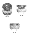
- FIGS. 16A and 16B show examples of markings on the outer surfaces of the trial inserts and cup of the present invention shown in FIGS. 15C and 15B , respectively.
- the number “8" on the trial insert shown designates an example of the implant insert size.
- the numbers “10” and “4" on the trial cup shown designate an example of the implant cup size.
- Whichever number on the trial cup is on the same side as the trial insert is used to designate the fully collapsed assembly height.
- the fully collapsed assembly height is 12mm, which includes a 4mm trial cup and an 8mm trial insert.
- the fully expanded assembly height is 18mm, which includes a 10mm trial cup and an 8mm trial insert.
- the embodiments described herein have applications in RSA as well as any other ball and socket joints that require dislocation and reduction, such as hip joints for example.
- FIG. 10 is a flowchart outlining the following five different trialing options that a surgeon may use in determining proper deltoid tension in a reverse shoulder procedure, for example, while FIG. 11 depicts each of these five different trial options wherein each option includes the use of a stem, cup and insert member.
- the five trialing options of FIGS. 10 and 11 are the following:
- a type I trial cup such as shown in FIGS. 2A-2D of the '363 Patent, for example, is coupled to broach 200.
- a type I trial insert screw up/down type
- FIG. 5A of the '363 Patent for example, is coupled to the type I trial cup.
- a type II trial cup 120 such as shown in FIGS. 4A-4D , for example, is coupled to broach 200.
- a type II trial insert 160 (slide in/out type) such as shown in FIG. 5A-5D , for example, is coupled to the type II trial cup.
- an implant cup 190 such as shown in FIGS. 6A-6B , for example, is coupled to implant stem 220.
- a type II trial insert 160 such as shown in FIG. 5A-5D , for example, may be dropped in to implant cup 190 in order to coupled the type II trial insert 160 and implant cup 190.
- a type I trial cup such as shown in FIGS. 2A-2D of the '363 Patent, for example, is coupled to implant stem 220.
- a type I trial insert such as shown in FIG. 5A-5D of the '363 Patent, for example, is coupled to the type I trial cup.
- a type II trial cup 120 such as shown in FIGS. 4A-4D , for example, is coupled to implant stem 220.
- a type II trial insert 160 such as shown in FIG. 5A-5D , for example, is coupled to the type II trial cup.
Landscapes
- Health & Medical Sciences (AREA)
- Transplantation (AREA)
- Orthopedic Medicine & Surgery (AREA)
- Heart & Thoracic Surgery (AREA)
- Cardiology (AREA)
- Oral & Maxillofacial Surgery (AREA)
- Engineering & Computer Science (AREA)
- Biomedical Technology (AREA)
- Vascular Medicine (AREA)
- Life Sciences & Earth Sciences (AREA)
- Animal Behavior & Ethology (AREA)
- General Health & Medical Sciences (AREA)
- Public Health (AREA)
- Veterinary Medicine (AREA)
- Physical Education & Sports Medicine (AREA)
- Prostheses (AREA)
Abstract
Description
- The present invention relates to a shoulder trial for reverse shoulder arthroplasty (RSA), and in particular it relates to such a trial including an insert and humeral cup that are configured to engage one another by sliding the insert from a transverse or lateral direction into engagement with the humeral cup.
- The successful outcome of RSA depends greatly on proper soft tissue tension in the shoulder joint. The stability of the shoulder joint is generally maintained from significant deltoid tension holding this ball and socket joint together. Some RSA systems require the surgeon to use a trial and error approach in establishing proper soft tissue tension. Such approaches often take several attempts before adequate stability is achieved.
- When performing a trialing step in a reverse shoulder procedure, one important aspect is to determine the correct height of the humeral insert implant that will ultimately be chosen for the patient. A series of humeral insert trials with varying heights is normally utilized to determine the correct height for the implant. By using thicker or thinner insert trials the soft tissue tension and joint range of motion can be optimized for the patient.
- Such trialing procedures generally include selecting a first trial insert, installing it into other parts of the shoulder system, reducing the joint, and then checking the joint for soft tissue tension and range of motion. The joint is then dislocated, and if the correct humeral insert implant height has been determined the reverse shoulder implantation proceeds. When the correct trial is determined, the soft tissue tension is significant, requiring the surgeon to apply extreme force to the humerus and surrounding soft tissues to reduce the joint. If no additional damage is done during this reduction process, the joint must then be dislocated to allow the surgeon to implant a joint replacement prosthesis.
- If the correct humeral insert height has not yet been determined, then a second trial insert with a different thickness than the first trial is selected. The second trial insert is installed and the joint is assessed. As a result of the trialing procedure, the reverse shoulder joint can be reduced and dislocated multiple times.
- Traditionally, each time the reverse shoulder joint is reduced and dislocated, the soft tissue has to be stretched in order for the glenosphere to be placed in or removed from the humeral insert. This stretching of the soft tissue can lead to joint instability and increased recovery time for the patient.
- The trial assembly of the present invention includes at least a trial cup and a trial insert. In one embodiment of the present invention, a recess or guide track of an insert trial is slid over a centering member or positive stop pin on a cup trial. Flanges on the cup trial are received within a groove of the insert trial as the guide track is slid over the centering member. After the centering member is located adjacent the deepest part of the guide track, the insert trial is preferably rotated in either a clockwise or counterclockwise direction substantially locking the lateral and vertical movement of the insert trial with respect to the cup trial. The rotational movement of the insert trial with respect to the cup trial can still occur.
- The lateral engagement and disengagement of the insert trial and insert cup allows any size insert trial and cup to be used during the trialing process in contrast to having to reduce and distract the trials from each other prior to and after use.
- In the past, there have been issues with achieving appropriate tensioning during RSA due to difficulties in inserting and removing the trials from between the humeral components and the glenosphere component on the glenoid. The trial assembly of the present invention provides a way of reducing and dislocating the joint without any temporary increase in joint tension that is usually experienced when reducing the ball up, over, and into the insert trial socket.
- In accordance with a first aspect of the present invention is a trial assembly comprising a trial cup and a trial insert. The trial cup has a distal end surface and a proximal end surface, the proximal end surface including first and second flanges and a centering member protruding outwardly therefrom. The trial insert includes a proximal end portion and a shaft portion having a distal end, the shaft portion having a groove around an outer circumference thereof and a recess in the distal end thereof. The trial insert is operatively coupled to the trial cup when the centering member is received in the recess of the trial insert and an engagement member on each of the first and second flanges is received within the groove of the trial insert.
- In one embodiment of this first aspect, the trial assembly further includes an elongated shaft having proximal and distal ends, the distal end surface of the trial cup adapted to lie adjacent to the proximal end of the elongated shaft when the trial cup is coupled to the elongated shaft.
- In another embodiment of this first aspect, the first and second flanges of the trial cup extend outwardly from at least a portion of an outer circumference of the proximal end surface of the trial cup.
- In yet another embodiment of this first aspect, the recess of the trial insert begins at the outer circumference of the shaft portion and terminates adjacent a central axis of the trial insert. When a longitudinal axis of the centering member is collinear with the central axis of the trial insert, the trial insert may be rotated in a radial direction about the central axis thereof. Further, rotating the trial insert 90° in either a first or second radial direction about a central axis thereof results in lateral locking of the trial insert and trial cup such that the trial insert and trial cup cannot be uncoupled by offsetting the longitudinal axis of the centering member of the trial cup and central axis of the trial insert. Further still, rotating the trial insert another 90° in either a first or second radial direction about the central axis thereof results in lateral unlocking of the trial insert and trial cup such that the trial insert and trial cup can be uncoupled by offsetting the longitudinal axis of the centering member of the trial cup and central axis of the trial insert.
- In still yet another embodiment of this first aspect, the proximal end portion of the trial insert has a concave recess therein.
- In still yet another embodiment of this first aspect, the proximal end portion of the insert includes an outer face having a plurality of calibration marks arranged thereon. The calibration marks are preferably located at 90° increments.
- In still yet another embodiment of this first aspect, an outer face of the insert includes a plurality of attachment locations adapted to be engaged by an adjustment tool for rotating the trial insert about the central axis thereof.
- In still yet another embodiment of this first aspect, the proximal end surface of the cup has a marker thereon.
- In still yet another embodiment of this first aspect, a size or height of the trial assembly is measured by the axial distance between a proximal end surface of the trial insert and the distal end surface of the trial cup.
- In accordance with a second aspect of the present invention is a trial assembly comprising a trial cup and a trial insert. The trial cup has a distal end surface and a proximal end surface, the proximal end surface including first and second flanges about a circumference thereof and a centering member protruding outwardly along a central longitudinal axis thereof. The trial insert includes a proximal end portion and a shaft portion having a distal end, the shaft portion having a groove around an outer circumference thereof and a recess in the distal end thereof, the recess begins about a circumference of the shaft and terminates adjacent a central longitudinal axis of the trial insert. The trial insert is operatively coupled to the trial cup when the centering member is received in the recess of the trial insert such that the central longitudinal axes of the centering member and trial insert are collinear and a portion of each of the first and second flanges is received at least partially within the groove of the trial insert.
- In one embodiment of this second aspect, when the central longitudinal axes of the centering member and trial insert are collinear, the trial insert may be rotated in a radial direction about the central longitudinal axis of the centering member. Further, rotating the trial insert 90° in either a first or second radial direction about a central axis thereof results in lateral locking of the trial insert and trial cup such that the trial insert and trial cup cannot be uncoupled by offsetting the longitudinal axis of the centering member of the trial cup and central axis of the trial insert. Further still, rotating the trial insert another 90° in either a first or second radial direction about the central axis thereof results in lateral unlocking of the trial insert and trial cup such that the trial insert and trial cup can be uncoupled by offsetting the longitudinal axis of the centering member of the trial cup and central axis of the trial insert.
- In another embodiment of this second aspect, a size or height of the trial assembly is measured by the axial distance between a proximal end surface of the trial insert and the distal end surface of the trial cup.
- In accordance with a third aspect of the present invention there is a trialing system in which a surgeon has five different trial options. The trialing system comprises at least one stem member having a shaft portion adapted to be received in a canal of a humeral bone of a patient. First and second trial cups and a prosthesis cup are each adapted to be coupled at a distal end thereof to the at least one stem member, the first trial cup having a base surface and a centering member protruding outwardly therefrom, and the second trial cup and prosthesis cup each having a proximal end surface including a recess therein. A first trial insert includes a proximal end portion and a shaft portion having a distal end, and a second trial insert includes a proximal end portion and a shaft portion having a distal end, the shaft portion having a recess in the distal end thereof. The shaft portion of the first trial insert is received at least partially within the recess of the second trial cup in order to couple the first trial insert and second trial cup. The centering member of the first trial cup is received in the recess in the distal end of the second trial insert in order to couple the first trial cup and second trial insert. The shaft portion of the second trial insert is received at least partially within the recess of the second trial cup in order to couple the second trial insert and second trial cup.
- A more complete appreciation of the subject matter of the present invention and the various advantages thereof can be realized by reference to the following detailed description in which reference is made to the accompanying drawings in which:
-
FIG. 1 is an exploded perspective view of one embodiment of a trial assembly of the present invention including a trial cup and a trial insert. -
FIG. 2 is an assembled perspective view of one embodiment of a trial assembly of the present invention including the trial cup and the trial insert ofFIG. 1 . -
FIG. 3 is a side view of the trial assembly shown inFIG. 2 . -
FIG. 4A is a perspective view of one embodiment of a trial cup of the present invention. -
FIG. 4B is a side view of the trial cup shown inFIG. 4A . -
FIG. 4C is a top view of the trial cup shown inFIG. 4A . -
FIG. 4D is a bottom view of the trial cup shown inFIG. 4A . -
FIG. 5A is a perspective view of one embodiment of a trial insert of the present invention. -
FIG. 5B is a side view of the trial insert shown inFIG. 5A . -
FIG. 5C is a top view of the trial insert shown inFIG. 5A . -
FIG. 5D is a bottom view of the trial insert shown inFIG. 5A . -
FIG. 5E shows an adjustment tool engaged to the trial insert shown inFIG. 5A . -
FIG. 6A is an exploded view of an implant cup and trial insert. -
FIG. 6B is an assembled view of the implant cup and trial insert shown inFIG. 6A . -
FIG. 7A is an exploded view of a broach, trial cup and trial insert. -
FIG. 7B is an assembled view of the broach, cup and trial insert shown inFIG. 7A . -
FIG. 8A is an exploded view of an implant stem, implant cup and trial insert. -
FIG. 8B is an assembled view of the implant stem, implant cup and trial insert shown inFIG. 8A . -
FIG. 9A is an exploded view of an implant stem, trial cup and trial insert. -
FIG. 9B is an assembled view of the implant stem, trial cup and trial insert shown inFIG. 9A . -
FIG. 10 is a flowchart showing two different trial options using a broach and three different trialing options using an implant stem. -
FIG. 11 shows five different trialing options using stem, cup and insert members of the present invention. -
FIGS. 12A-C show another embodiment of an expandable trial of the present invention having a trial insert that is slidingly received by a trial cup, wherein the expandable trial expands and collapses by way of the interaction of a pin on the trial cup and a helical groove on the trial insert. -
FIGS. 13A-C show another embodiment of a trial cup of the present invention having a spring actuated sliding pin. -
FIGS. 14A-B show another embodiment of a trial insert of the present invention having a helical groove wherein at one end thereof there is a lead-in slot. -
FIGS. 15A-C show another embodiment of an expandable trial of the present invention including trial cup as shown inFIGS. 13A-C and trial insert as shown inFIGS. 14A-B . -
FIGS. 16A-B show the markings on the outer surfaces of the trial inserts and cup of the present invention shown inFIGS. 15C and 15B , respectively. - Referring to
Figs. 1-3 , there is shown an embodiment of a trial assembly of the present invention designated generally byreference numeral 100. As shown in those figures,trial assembly 100 includes atrial cup 120 and atrial insert 160. -
FIGS. 4A-D show an embodiment oftrial cup 120. As shown in these figures,trial cup 120 includes adistal end surface 122 and aproximal end surface 124.Proximal end surface 124 includes first andsecond flanges member 130 protruding outwardly therefrom.Proximal end surface 124 preferably includes amarker 144 thereon as shown inFIG. 4D . - First and
second flanges outer circumference 136 ofproximal end surface 124 oftrial cup 120. First andsecond flanges engagement member Engagement members second flanges Engagement members top surface FIGS. 4A and 4B , axis A1 is a central longitudinal axis through centeringmember 130 and is also is a central longitudinal axis fortrial cup 120. - Protruding outwardly from
distal end surface 122 of trial cup are preferably first andsecond coupling members members FIGS. 7A-B and9A-B , for example, in order to couple the stem andtrial cup 120. -
FIGS. 5A-D show an embodiment oftrial insert 160. As shown in these figures,trial insert 160 includes aproximal end portion 162 and ashaft portion 164 having adistal end 166.Shaft portion 164 has agroove 168 around anouter circumference 170 thereof and arecess 172 in thedistal end 166 thereof. Recess 172 oftrial insert 160 preferably begins atouter circumference 170 ofshaft portion 164 and preferably terminates adjacent a central axis A2 of thetrial insert 160. - As shown in
FIG. 5C ,proximal end portion 162 oftrial insert 160 has aconcave recess 180 therein.Concave recess 180 is adapted to contact and house a portion of a glenosphere (not shown).Proximal end portion 162 oftrial insert 160 includes anouter face 182 preferably having a plurality ofattachment locations 184 and calibration marks 186 arranged thereon. Theattachment locations 184 are preferably located at 30° increments aboutouter face 182, but may be located from one another at increments greater or less than 30°. The calibration marks 186 are preferably located at 90° increments aboutouter face 182, but may be located from one another at increments greater or less than 90°.Attachment locations 184 are adapted to be engaged by anadjustment tool 188 as shown inFIG. 5E , for example, for rotating thetrial insert 160 about central axis A2 thereof. - A reverse shoulder implant typically consists of five components: a humeral stem, a humeral cup, a humeral insert, a glenosphere baseplate, and a glenosphere. The embodiment of
trial assembly 100 shown inFIGS. 1-3 includes two distinct components, namelytrial cup 120 andtrial insert 160, which are designed to allow a surgeon to determine which size humeral cup and humeral insert are needed to provide a shoulder joint with optimal deltoid tension in a RSA procedure. Bothtrial cup 120 andtrial insert 160 are designed to work with other components or parts of a reverse shoulder implant and instrumentation thereof as part of a complete system in order to give a surgeon intraoperative flexibility and to accommodate surgeon preference. In addition, the design oftrial cup 120 andtrial insert 160 allowstrial insert 160 to slide intotrial cup 120 from a direction substantially transverse to the direction of trial cup axis A1, which minimizes soft tissue stretching when reducing or dislocating a reverse shoulder during a trialing process, and gives a surgeon the ability to perform a trialing procedure using instruments only or some combination of instruments and implants. - The design of
trial assembly 100 overcomes the challenge of soft tissue stretching when reducing or dislocating a joint by allowing the trial humeral insert to slide into the trial humeral cup at an angle substantially transverse to the axis of the cup. Since thetrial insert 160 can enter thetrial cup 120 at a transverse angle to trial cup axis A1, reduction or dislocation of the joint can be achieved without the need to pull the glenosphere over the rim oftrial insert 160. Soft tissue stretching is therefore minimized. - In one method of the present invention,
trial insert 160 is operatively coupled totrial cup 120 when centeringmember 130 oftrial cup 120 is received inrecess 172 oftrial insert 160 and anengagement member second flanges trial cup 120 is received withingroove 168 oftrial insert 160. When centeringmember 130 is located withinrecess 172 oftrial insert 160 and longitudinal axis A1 of centeringmember 130 is collinear with central axis A2 oftrial insert 160,trial insert 160 may be rotated in a radial direction about central axis A2 thereof. Thetrial insert 160 can be reversibly locked into thetrial cup 120 simply by turning thetrial insert 160 approximately 15 degrees to approximately 165 degrees after initially engaging thetrial insert 160 andtrial cup 120. For example, after axes A1, A2 become collinearly oriented, rotating thetrial insert 160 approximately 90° in either a first or second radial direction about central axis A2 thereof results in lateral locking oftrial insert 160 andtrial cup 120 such thattrial insert 160 andtrial cup 120 cannot be uncoupled by offsetting longitudinal axis A1 of the centeringmember 130 oftrial cup 120 and central axis A2 oftrial insert 160.Rotating trial insert 160 approximately another 90° in either a first or second radial direction about central axis A2 thereof results in lateral unlocking oftrial insert 160 andtrial cup 120 such thattrial insert 160 andtrial cup 120 can be uncoupled by offsetting longitudinal axis A1 of centeringmember 130 oftrial cup 120 and central axis A2 oftrial insert 160. - When operatively coupled,
trial insert 160 can be rotated with respect totrial cup 120 by using an attachment tool having an end that can be received inattachment locations 184. A surgeon can estimate the amount of degrees thattrial insert 160 has been rotated with respect totrial cup 120 by visualizing the movement of calibration marks 186 located onouter face 182 or by visualizing the movement of calibration marks 186 with respect tomarker 144 located onproximal end surface 124 oftrial cup 120. - As shown in
FIG. 3 and5B , a first height H1 is defined by the planar distance between aproximal end surface 161 anddistal surface 163 ofproximal end portion 162 oftrial insert 160. As shown inFIG. 3 and4B , a second height H2 is defined by the planar distance between atop surface engagement members distal end surface 122 oftrial cup 120. A size or height H oftrial assembly 100 is measured by the axial or planar distance betweenproximal surface 161 oftrial insert 160 anddistal end surface 122 oftrial cup 120 as shown inFIG. 3 . - During the trial process, a surgeon may use one or more of a plurality of different sized trial cups and inserts. Each
insert 160 preferably has a first height H1 between 4mm and 12mm in increments of 2mm as shown in the chart below. A surgeon may then use one or more of a plurality of different sized trial cups 120. Eachcup 120 preferably has a second height H2 that is either 4mm or 10mm as shown in the chart below. The following chart is a non-limiting example of the different sized trial inserts 160, trial cups 120 and the resultant total height H (8mm, 10mm, 12mm, 14mm, 16mm, 18mm, 20mm and 22mm) that can be achieved when trial inserts 160 and trial cups 120 are assembled and used during the trialing process: -
4mm Insert 6mm Insert 8mm Insert 10mm Insert 12mm Insert 4mm Cup 8 10 12 14 16 10mm Cup 14 16 18 20 22 - The design of
trial assembly 100 overcomes the challenge of having one system allowing multiple intraoperative options with regard to trialing by allowing thetrial cup 120 to be connected to either abroach 200 as shown inFIGS. 7A-B orhumeral stem implant 220 as shown inFIGS. 9A-B , and also by allowing thetrial insert 160 to be able to be connected to eithertrial cup 120 orimplant cup 190 as shown inFIGS. 6A-6B and8A-8B . - Surgeon preferences result in implants and instruments being used in different combinations. For example, some surgeons prefer to perform the trialing procedure off of a broach including cutting
portions 210 such as teeth, for example, as shown inFIGS. 7A-7B used to create a cavity into which a humeral stem implant will eventually be placed. Some surgeons instead prefer to trial off of the humeral stem itself as shown inFIGS. 8A-8B and9A-9B . As a result, it is advantageous for any trial humeral cup to be able to be connected to both the broach and humeral stem implant. Likewise, some surgeons prefer to perform the trialing procedure off of a trial humeral cup and some surgeons prefer to trial off of the humeral cup implant. Therefore it is advantageous for the humeral insert trial to be able to be connected to both the trial humeral cup and the humeral cup implant. - The
same trial insert 160 that can be slid into engagement withtrial cup 120 at an angle transverse to trial cup axis A1 and can also be dropped into a humeral cup implant along an axis coincident with both the humeral cup implant andtrial insert 160. The attachment mechanisms that permit a connection between an implant component and a trial do not compromise the integrity of the attachment mechanisms used to connect two implant components. Such a design allows a surgeon to trial off of an implant with confidence that the trialing procedure is not damaging the implant attachment mechanisms which could possibly compromise the performance of the implant after final assembly. - In other embodiments,
trial insert 160 may be able to engagetrial cup 120 by sliding in a lateral direction into engagement with thetrial cup 120, with trialing occurring as thetrial insert 160 expands away from and collapses towardtrial cup 120. For example, groove 168 oftrial insert 160 may be in the form of a helical groove aboutshaft portion 164. The motion of trial insert along axis A1 oftrial cup 120 may be guided by the interaction between the helical groove and anengagement member 133 or 125, for example. In such an embodiment, centeringmember 130 oftrial cup 120 will have a larger height and recess 172 oftrial insert 160 will have a greater depth such that the centeringmember 130 will remain at least partially withinrecess 172 astrial insert 160 expands and collapses with respect totrial cup 120. - The interaction of the helical groove and engagement member occurs much like that shown in
U.S. Pat. No. 8,257,363 ("the '363 Patent") titled "Expandable Reverse Shoulder Trial," the disclosure of which is hereby incorporated by reference in its entirety. When trial insert 160 first becomes operatively engaged totrial cup 120,trial insert 160 may then be rotated into a fully collapsed or neutral position. Such a device may allow a surgeon to easily reduce the shoulder joint. - Preferably,
trial insert 160 may then be advanced to a position where optimal deltoid tension is achieved. At this position, thetrial insert 160 andtrial cup 120 are preferably calibrated such that the surgeon may determine a liner thickness corresponding to a dialed position of the insert with respect to the cup. - Preferably, the surgeon may then easily collapse the trial back to the neutral position and simply dislocate the joint. Further, the trial may also be preferably expanded prior to joint reduction and collapsed prior to joint dislocation repeatedly, depending on surgeon preference. Once the trial has been optimized, a surgeon preferably records the dialed position of the expanded trial. This measurement should preferably be the liner thickness. If this measurement does not correspond to the size of a particular liner in the system, the surgeon may select a next larger sized liner. At this time, the surgeon may remove the trial and then implant a prosthesis including a humeral cup and the selected liner.
- Another embodiment of such an
expandable trial 300 is shown inFIGS. 12A-C . In this embodiment,trial insert 360 engagestrial cup 320 by sliding in a lateral direction into engagement with thetrial cup 320. Apin 330 extending outwardly from aninner wall 332 oftrial cup 320 is received in a portion of ahelical groove 368, with trialing occurring astrial insert 360 expands away from and collapses towardtrial cup 320 via the interaction ofpin 330 engaged tohelical groove 368. For example,helical groove 368 oftrial insert 360 may be formed about ashaft portion 364 oftrial insert 360. The motion oftrial insert 360 along an axis A3 oftrial cup 120 may be guided by the interaction between thehelical groove 368 and engagement member orpin 330. -
FIG. 12B showsexpandable trial 300 in a fully collapsed position whileexpandable trial 300 is shown inFIG. 12C in an expanded position withpin 330 being in engagement with one of a plurality of engagement recesses 380 formed alonghelical groove 368.Helical groove 368 preferably includes sixengagement recesses 380, wherein theexpandable trial 300 expands or collapses 1mm aspin 330 engages anadjacent engagement recess 380 alonghelical groove 368.Helical groove 368 may include fewer or more than sixengagement recesses 380 and the pitch ofhelical groove 368 may be such thatexpandable trial 300 expands or collapses more than or less than 1mm aspin 330 engages anadjacent engagement recess 380 alonghelical groove 368. - Another embodiment of such an expandable trial 400 is shown in
FIGS. 13A-15C .FIGS. 13A-C show one embodiment of atrial cup 420 having a spring actuated slidingpin 430 extending outwardly from an inner wall 432 oftrial cup 420.FIGS. 14A-B show one embodiment of atrial insert 460 having ahelical groove 468 having one end thereof adjacent a lead-inslot 480 located at adistal end 466 of ashaft portion 464 ofinsert trial 460. In this embodiment,trial insert 460 engagestrial cup 420 when slidingpin 430 is received in lead-inslot 480 and ontohelical groove 468. Slidingpin 430 extending outwardly from an inner wall 432 oftrial cup 420 is received in a portion of ahelical groove 468, with trialing occurring astrial insert 460 expands away from and collapses towardtrial cup 420 via the interaction ofpin 430 engaged tohelical groove 468. The motion oftrial insert 460 along a central longitudinal axis oftrial cup 420 may be guided by the interaction between thehelical groove 468 and engagement member orpin 430. -
FIGS. 15A shows lead-inslot 480 oftrial insert 460 adjacent slidingpin 430 oftrial insert 420 prior to slidingpin 430 being received in lead-inslot 480.FIG. 15C shows expandable trial 400 in a fully collapsed position while expandable trial 400 is shown inFIG. 15B in an expanded position withpin 430 being in engagement with one of a plurality of engagement recesses 480 formed alonghelical groove 468. - As described with respect to
expandable trial 300,helical groove 468 of expandable trial 400 preferably includes sixengagement recesses 480, wherein the expandable trial 400 expands or collapses 1mm aspin 430 engages anadjacent engagement recess 480 alonghelical groove 468.Helical groove 468 may include fewer or more than sixengagement recesses 480 and the pitch ofhelical groove 468 may be such that expandable trial 400 expands or collapses more than or less than 1mm aspin 430 engages anadjacent engagement recess 480 alonghelical groove 468. -
FIGS. 16A and 16B show examples of markings on the outer surfaces of the trial inserts and cup of the present invention shown inFIGS. 15C and 15B , respectively. The number "8" on the trial insert shown designates an example of the implant insert size. The numbers "10" and "4" on the trial cup shown designate an example of the implant cup size. Whichever number on the trial cup is on the same side as the trial insert is used to designate the fully collapsed assembly height. As shown inFIG. 16A , the fully collapsed assembly height is 12mm, which includes a 4mm trial cup and an 8mm trial insert. As shown inFIG. 16B , the fully expanded assembly height is 18mm, which includes a 10mm trial cup and an 8mm trial insert. - The embodiments described herein have applications in RSA as well as any other ball and socket joints that require dislocation and reduction, such as hip joints for example.
- The aforementioned trial systems allow for trialing to occur off of a
broach 200 as shown inFIGS. 7A-7B , for example, or off of animplant stem 220 as shown inFIGS. 8A-8B .FIG. 10 is a flowchart outlining the following five different trialing options that a surgeon may use in determining proper deltoid tension in a reverse shoulder procedure, for example, whileFIG. 11 depicts each of these five different trial options wherein each option includes the use of a stem, cup and insert member. The five trialing options ofFIGS. 10 and11 are the following: - In a
first trialing option 500, a type I trial cup such as shown inFIGS. 2A-2D of the '363 Patent, for example, is coupled to broach 200. A type I trial insert (screw up/down type) such as shown inFIG. 5A of the '363 Patent, for example, is coupled to the type I trial cup. - In a
second trialing option 600, a type IItrial cup 120 such as shown inFIGS. 4A-4D , for example, is coupled to broach 200. A type II trial insert 160 (slide in/out type) such as shown inFIG. 5A-5D , for example, is coupled to the type II trial cup. - In a
third trialing option 700, animplant cup 190 such as shown inFIGS. 6A-6B , for example, is coupled toimplant stem 220. A type IItrial insert 160 such as shown inFIG. 5A-5D , for example, may be dropped in to implantcup 190 in order to coupled the type IItrial insert 160 andimplant cup 190. - In a
forth trialing option 800, a type I trial cup such as shown inFIGS. 2A-2D of the '363 Patent, for example, is coupled toimplant stem 220. A type I trial insert such as shown inFIG. 5A-5D of the '363 Patent, for example, is coupled to the type I trial cup. - In a
fifth trialing option 900, a type IItrial cup 120 such as shown inFIGS. 4A-4D , for example, is coupled toimplant stem 220. A type IItrial insert 160 such as shown inFIG. 5A-5D , for example, is coupled to the type II trial cup. - Although the invention herein has been described with reference to particular embodiments, it is to be understood that these embodiments are merely illustrative of the principles and applications of the present invention. It is therefore to be understood that numerous modifications may be made to the illustrative embodiments and that other arrangements may be devised without departing from the scope of the present invention as defined by the appended claims.
Claims (15)
- A trial assembly comprising:a trial cup having a distal end surface and a proximal end surface, the proximal end surface including first and second flanges and a centering member protruding outwardly therefrom; anda trial insert including a proximal end portion and a shaft portion having a distal end, the shaft portion having a groove around an outer circumference thereof and a recess in the distal end thereof,wherein the trial insert is operatively coupled to the trial cup when the centering member is received in the recess of the trial insert and an engagement member on each of the first and second flanges is received within the groove of the trial insert.
- The trial assembly of claim 1, further including an elongate shaft having proximal and distal ends, the distal end surface of the trial cup adapted to lie adjacent to the proximal end of the elongate shaft when the trial cup is coupled to the elongate shaft.
- The trial assembly of claim 1, wherein the first and second flanges extend outwardly from at least a portion of an outer circumference of the proximal end surface of the trial cup.
- The trial assembly of claim 1, wherein the recess of the trial insert begins at the outer circumference of the shaft portion and terminates adjacent a central axis of the trial insert.
- The trial assembly of claim 4, wherein when a longitudinal axis of the centering member is collinear with the central axis of the trial insert, the trial insert may be rotated in a radial direction about the central axis thereof.
- The trial assembly of claim 5, wherein rotating the trial insert 90° in either a first or second radial direction about a central axis thereof results in lateral locking of the trial insert and trial cup such that the trial insert and trial cup cannot be uncoupled by offsetting the longitudinal axis of the centering member of the trial cup and central axis of the trial insert.
- The trial assembly of claim 6, wherein rotating the trial insert another 90° in either a first or second radial direction about the central axis thereof results in lateral unlocking of the trial insert and trial cup such that the trial insert and trial cup can be uncoupled by offsetting the longitudinal axis of the centering member of the trial cup and central axis of the trial insert.
- The trial assembly of claim 1, wherein the proximal end portion of the trial insert has a concave recess therein.
- The trial assembly of claim 1, wherein the proximal end portion of the insert includes an outer face having a plurality of calibration marks arranged thereon.
- The trial assembly of claim 1, wherein an outer face of the insert includes a plurality of attachment locations adapted to be engaged by an adjustment tool for rotating the trial insert about the central axis thereof.
- The trial assembly of claim 1,
wherein the first and second flanges of the trial cup extend about a circumference of the proximal end surface thereof and the centering member of the trial cup protrudes outwardly along a central longitudinal axis of the proximal end surface thereof,
wherein the recess of the trial insert begins about a circumference of the shaft portion and terminates adjacent a central longitudinal axis thereof, and
wherein the operative coupling of the trial insert to the trial cup further includes the central longitudinal axes of the centering member and trial insert being collinear. - The trial assembly of claim 11, wherein when the central longitudinal axes of the centering member and trial insert are collinear, the trial insert may be rotated in a radial direction about the central longitudinal axis of the centering member.
- The trial assembly of claim 12, wherein rotating the trial insert 90° in either a first or second radial direction about a central axis thereof results in lateral locking of the trial insert and trial cup such that the trial insert and trial cup cannot be uncoupled by offsetting the longitudinal axis of the centering member of the trial cup and central axis of the trial insert.
- The trial assembly of claim 13, wherein rotating the trial insert another 90° in either a first or second radial direction about the central axis thereof results in lateral unlocking of the trial insert and trial cup such that the trial insert and trial cup can be uncoupled by offsetting the longitudinal axis of the centering member of the trial cup and central axis of the trial insert.
- The trial assembly of any of claims 1 or 11, wherein a size of the trial assembly is measured by the axial distance between a proximal end surface of the trial insert and the distal end surface of the trial cup.
Applications Claiming Priority (2)
| Application Number | Priority Date | Filing Date | Title |
|---|---|---|---|
| US13/484,557 US8663334B2 (en) | 2012-05-31 | 2012-05-31 | Lateral entry insert for cup trial |
| US13/767,074 US8906102B2 (en) | 2012-05-31 | 2013-02-14 | Lateral entry insert for cup trial |
Publications (2)
| Publication Number | Publication Date |
|---|---|
| EP2668930A1 true EP2668930A1 (en) | 2013-12-04 |
| EP2668930B1 EP2668930B1 (en) | 2015-01-21 |
Family
ID=48537789
Family Applications (1)
| Application Number | Title | Priority Date | Filing Date |
|---|---|---|---|
| EP13169019.0A Active EP2668930B1 (en) | 2012-05-31 | 2013-05-23 | Lateral entry insert for cup trial |
Country Status (2)
| Country | Link |
|---|---|
| US (1) | US8906102B2 (en) |
| EP (1) | EP2668930B1 (en) |
Cited By (5)
| Publication number | Priority date | Publication date | Assignee | Title |
|---|---|---|---|---|
| WO2017034845A1 (en) | 2015-08-21 | 2017-03-02 | Hip Innovation Technology, LLC | Surgical trays, instruments and methods for implanting a hip replacement prosthesis |
| US10368998B2 (en) | 2015-01-15 | 2019-08-06 | DePuy Synthes Products, Inc. | Modular reverse shoulder orthopaedic implant and method of implanting the same |
| WO2022120060A1 (en) * | 2020-12-03 | 2022-06-09 | Zimmer, Inc. | Methods and apparatuses for trialing a humeral head |
| US11678993B2 (en) | 2020-02-19 | 2023-06-20 | Howmedica Osteonics Corp. | Humeral head trial with flexure |
| US11951022B2 (en) | 2015-07-27 | 2024-04-09 | Hip Innovation Technology, Llc. | Tool and method for separating a femoral cup from an acetabular ball in an implanted hip prosthesis |
Families Citing this family (24)
| Publication number | Priority date | Publication date | Assignee | Title |
|---|---|---|---|---|
| US20070225821A1 (en) | 2006-03-21 | 2007-09-27 | Axiom Orthopaedics, Inc. | Femoral and humeral stem geometry and implantation method for orthopedic joint reconstruction |
| US8579985B2 (en) | 2006-12-07 | 2013-11-12 | Ihip Surgical, Llc | Method and apparatus for hip replacement |
| WO2011044586A1 (en) * | 2009-10-10 | 2011-04-14 | Simplicity Orthopedics, Inc. | Method and apparatus for restoring a joint, including the provision and use of a longitudinally-adjustable and rotationally-adjustable joint prosthesis |
| EP2586387A1 (en) | 2011-10-31 | 2013-05-01 | Tornier Orthopedics Ireland Ltd. | Bone reamer |
| US9421106B2 (en) | 2011-12-07 | 2016-08-23 | Howmedica Osteonics Corp. | Reverse shoulder baseplate with alignment guide for glenosphere |
| US8906102B2 (en) * | 2012-05-31 | 2014-12-09 | Howmedica Osteonics Corp. | Lateral entry insert for cup trial |
| US8663334B2 (en) * | 2012-05-31 | 2014-03-04 | Howmedica Osteonics Corp. | Lateral entry insert for cup trial |
| GB2507640B (en) | 2012-09-10 | 2015-08-26 | Acumed Llc | Radial head prosthesis with floating articular member |
| BR112015007174A8 (en) | 2012-10-29 | 2018-04-24 | Tornier Orthopedics Ireland Ltd | Modular reverse shoulder prosthesis and respective systems |
| US20140128986A1 (en) * | 2012-11-06 | 2014-05-08 | Ihip Surgical, Llc | Monoblock head and neck unit for total hip replacement |
| PL3054896T3 (en) * | 2013-10-13 | 2018-02-28 | 41Hemiverse Ag | Joint implant |
| FR3029769A1 (en) | 2014-12-10 | 2016-06-17 | Tornier Sa | KIT FOR A PROSTHESIS OF SHOULDER |
| US9566162B2 (en) * | 2015-03-03 | 2017-02-14 | Biomet Manufacturing, Llc | Adjustable humeral tray for shoulder arthroplasty |
| US9763792B2 (en) * | 2015-10-01 | 2017-09-19 | Acumed Llc | Radial head prosthesis with rotate-to-lock interface |
| AU2016371425B2 (en) | 2015-12-16 | 2021-09-02 | Howmedica Osteonics Corp. | Patient specific instruments and methods for joint prosthesis |
| US9943414B2 (en) * | 2015-12-30 | 2018-04-17 | Wasas, Llc. | System and method for non-binding allograft subtalar joint implant |
| US10390972B2 (en) | 2016-01-15 | 2019-08-27 | Howmedica Osteonics Corp. | Humeral trial adaptor |
| EP3445292B1 (en) | 2016-04-19 | 2022-12-21 | Imascap SAS | Pre-operatively planned humeral implant and planning method |
| US11974925B2 (en) | 2017-09-25 | 2024-05-07 | Howmedica Osteonics Corp. | Patient specific stemless prosthesis anchor components |
| CA3087066A1 (en) * | 2017-12-29 | 2019-07-04 | Tornier, Inc. | Patient specific humeral implant components |
| EP3520738B1 (en) | 2018-01-31 | 2021-01-06 | Tornier | Prosthesis for a fractured long bone |
| EP3833277A1 (en) | 2018-08-10 | 2021-06-16 | Tornier, Inc. | Guides and instruments for improving accuracy of glenoid implant placement |
| USD938590S1 (en) | 2019-10-01 | 2021-12-14 | Howmedica Osteonics Corp. | Humeral implant |
| AU2021200854A1 (en) | 2020-03-03 | 2021-09-16 | Howmedica Osteonics Corp. | Glenoid implant with additively manufactured fixation posts |
Citations (5)
| Publication number | Priority date | Publication date | Assignee | Title |
|---|---|---|---|---|
| GB2001247A (en) * | 1977-07-21 | 1979-01-31 | Minnesota Mining & Mfg | Prosthetic hip joint device |
| US5879401A (en) * | 1996-05-17 | 1999-03-09 | Johnson & Johnson Professional, Inc. | Acetabular trial |
| EP1314407A1 (en) * | 2001-11-21 | 2003-05-28 | Sulzer Orthopedics Ltd. | Shoulder prothesis |
| DE202008008565U1 (en) * | 2008-06-18 | 2008-08-21 | Aesculap Ag | Modular trial implant system |
| US8257363B2 (en) | 2007-10-12 | 2012-09-04 | Howmedica Osteonics Corp. | Expandable reverse shoulder trial |
Family Cites Families (225)
| Publication number | Priority date | Publication date | Assignee | Title |
|---|---|---|---|---|
| US3102536A (en) | 1960-12-07 | 1963-09-03 | Robert M Rose | Hip prosthesis |
| SU440014A1 (en) | 1972-05-04 | 1978-08-05 | Саратовский государственный медицинский институт | Endoprosthesis of proximal end of thighbone |
| GB1438950A (en) | 1972-09-04 | 1976-06-09 | Nat Res Dev | Prosthetic devices |
| GB1544403A (en) | 1975-01-31 | 1979-04-19 | Nat Res Dev | Endoprosthetic bone joint devices |
| US3978528A (en) | 1975-06-26 | 1976-09-07 | Howmedica, Inc. | Bone and joint prosthesis |
| US4003095A (en) | 1976-04-29 | 1977-01-18 | Howmedica, Inc. | Trispherical prosthetic shoulder device |
| DE2829676A1 (en) | 1978-07-06 | 1980-01-24 | Gmt Medizinische Technik Gmbh | ENDOPROTHESIS |
| FR2545352B1 (en) | 1983-05-02 | 1990-01-19 | Gabard Jean Jacques | SHOULDER PROSTHESIS |
| US4524467A (en) | 1983-11-21 | 1985-06-25 | Joint Medical Products Corp. | Apparatus for constraining a socket bearing in an artificial joint |
| USD285968S (en) | 1984-01-31 | 1986-09-30 | Kinnett James G | Glenoid prosthesis component for total shoulder prosthesis system |
| DE3433264C2 (en) | 1984-09-11 | 1986-10-02 | S + G Implants GmbH, 2400 Lübeck | Tibial part for a knee joint endoprosthesis |
| US4795468A (en) | 1987-12-23 | 1989-01-03 | Zimmer, Inc. | Mechanism and method for locking a bearing insert to the base of a prosthetic implant |
| US5080673A (en) | 1988-02-03 | 1992-01-14 | Intermedics Orthopedics, Inc. | Glenoid prosthesis and method of use |
| US4944757A (en) | 1988-11-07 | 1990-07-31 | Martinez David M | Modulator knee prosthesis system |
| US4936853A (en) | 1989-01-11 | 1990-06-26 | Kirschner Medical Corporation | Modular knee prosthesis |
| GB2251795B (en) | 1991-01-17 | 1995-02-08 | Minnesota Mining & Mfg | Orthopaedic implant |
| US5609639A (en) | 1991-02-04 | 1997-03-11 | Walker; Peter S. | Prosthesis for knee replacement |
| FR2685633B1 (en) * | 1991-12-27 | 1998-02-27 | Tornier Sa | MODULAR HUMER PROSTHESIS. |
| FR2689756B1 (en) | 1992-04-08 | 1999-07-09 | Fabrication Etu Realisa Implan | ARTICULATION HEAD FOR PROSTHETIC ELEMENT. |
| DE4238832C1 (en) * | 1992-11-17 | 1994-08-11 | Plus Endoprothetik Ag | Shoulder joint endoprosthesis |
| FR2699400B1 (en) | 1992-12-18 | 1995-02-24 | Medinov Sa | Humeral stem for shoulder prosthesis. |
| US5413604A (en) | 1992-12-24 | 1995-05-09 | Osteonics Corp. | Prosthetic knee implant for an anterior cruciate ligament deficient total knee replacement |
| US5489309A (en) * | 1993-01-06 | 1996-02-06 | Smith & Nephew Richards Inc. | Modular humeral component system |
| US5961555A (en) * | 1998-03-17 | 1999-10-05 | Huebner; Randall J. | Modular shoulder prosthesis |
| US5910171A (en) | 1993-03-12 | 1999-06-08 | Hospital For Joint Diseases | Components for a modular shoulder and hip prosthesis |
| GB9314832D0 (en) | 1993-07-16 | 1993-09-01 | Walker Peter S | Prostheses for knee replacement |
| DE9312218U1 (en) | 1993-08-16 | 1993-10-21 | Howmedica Gmbh | Endoprosthesis for the shoulder joint |
| US7722678B2 (en) | 1993-11-01 | 2010-05-25 | Biomet Manufacturing Corp. | Intramedullary compliant fixation |
| US6197065B1 (en) | 1993-11-01 | 2001-03-06 | Biomet, Inc. | Method and apparatus for segmental bone replacement |
| US5507817A (en) * | 1994-02-22 | 1996-04-16 | Kirschner Medical Corporation | Modular humeral prosthesis for reconstruction of the humerus |
| GB9405746D0 (en) | 1994-03-23 | 1994-05-11 | Howmedica | Prosthetic patello femoral joint assembly |
| GB9418492D0 (en) | 1994-09-14 | 1994-11-02 | Goodfellow John W | Prosthetic knee joint device |
| FR2727002B1 (en) | 1994-11-18 | 1997-01-03 | Tornier Sa | HUMERAL PROSTHESIS IN SPHERE |
| FR2727857B1 (en) * | 1994-12-08 | 1997-01-24 | Cedior | TOTAL SHOULDER PROSTHESIS |
| US5569263A (en) | 1995-01-12 | 1996-10-29 | Orthopaedic Innovations, Inc. | Adjustable provisional articulating device |
| US5728161A (en) * | 1995-06-08 | 1998-03-17 | Depuy Orthopedics, Inc. | Large taper modular shoulder prosthesis |
| FR2741796B1 (en) | 1995-11-30 | 1998-03-27 | Tornier Sa | DEVICE FOR FIXING A PROSTHESIS AND PARTICULARLY A GLENOIDAL PROSTHESIS OF OMOPLATE |
| US5702470A (en) | 1996-02-23 | 1997-12-30 | Kinetikos Medical Incorporated | Prosthetic wrist implant and related method of implantation |
| FR2747302B1 (en) | 1996-04-11 | 1998-09-11 | Tornier Sa | ANKLE PROSTHESIS |
| US5964808A (en) | 1996-07-11 | 1999-10-12 | Wright Medical Technology, Inc. | Knee prosthesis |
| GB9707371D0 (en) * | 1997-04-11 | 1997-05-28 | Minnesota Mining & Mfg | A modular humeral prosthesis |
| GB9707853D0 (en) * | 1997-04-18 | 1997-06-04 | Headcorn Instrumentation Ltd | Prosthesis |
| FR2768330B1 (en) | 1997-09-12 | 2000-01-21 | Tornier Sa | HUMERAL PROSTHESIS WITH INDEXED SPHERE |
| US6123728A (en) | 1997-09-17 | 2000-09-26 | Smith & Nephew, Inc. | Mobile bearing knee prosthesis |
| FR2768613B1 (en) | 1997-09-23 | 1999-12-17 | Tornier Sa | KNEE PROSTHESIS WITH ROTATABLE PLATFORM |
| FR2773469B1 (en) * | 1998-01-09 | 2000-03-03 | Alain Leonard | SURGICAL EQUIPMENT FOR THE IMPLANTATION OF A TOTAL SHOULDER PROSTHESIS, AND TOTAL SHOULDER PROSTHESIS |
| US6494913B1 (en) * | 1998-03-17 | 2002-12-17 | Acumed, Inc. | Shoulder prosthesis |
| US7189261B2 (en) * | 1998-04-03 | 2007-03-13 | Smith & Nephew, Inc. | Modular humeral prosthesis and method |
| DE19820015C2 (en) | 1998-05-06 | 2000-09-07 | Schaefer Micomed Gmbh | Prosthetic wrist |
| US6228119B1 (en) * | 1998-06-09 | 2001-05-08 | Depuy Orthopaedics, Inc. | Modular glenoid assembly |
| EP1112049B1 (en) * | 1998-09-11 | 2003-11-26 | Argomedical AG | Implantable prosthesis having at least two sections which can be displaced in relation to one another, and the use of displaceable sections |
| US6045582A (en) * | 1998-09-25 | 2000-04-04 | Sulzer Orthopedics Inc. | Implantable humeral shoulder prosthesis having extended articular surface |
| US6500208B1 (en) | 1998-10-16 | 2002-12-31 | Biomet, Inc. | Nonmodular joint prosthesis convertible in vivo to a modular prosthesis |
| US6129764A (en) * | 1998-11-24 | 2000-10-10 | Stryker Technologies Corporation | Modular prosthetic joint components |
| US6197062B1 (en) * | 1999-01-11 | 2001-03-06 | Howmedica Osteonics, Corp. | Modular shoulder prosthesis system |
| US6283999B1 (en) * | 1999-01-29 | 2001-09-04 | Depuy Orthopaedics, Inc. | Shoulder prothesis with humeral fracture stem |
| EP1043001A3 (en) * | 1999-04-07 | 2000-10-18 | Depuy Orthopaedics, Inc. | Collarless shoulder arthroplasty prosthesis |
| US6749637B1 (en) * | 1999-09-24 | 2004-06-15 | Baehler Andre | Endoprosthesis for a shoulder joint |
| DE29918669U1 (en) * | 1999-10-22 | 1999-12-30 | Keramed Medizintechnik Gmbh | Shoulder endoprosthesis |
| US6217618B1 (en) | 1999-10-26 | 2001-04-17 | Bristol-Myers Squibb Company | Tibial knee component with a mobile bearing |
| US6210444B1 (en) | 1999-10-26 | 2001-04-03 | Bristol-Myers Squibb Company | Tibial knee component with a mobile bearing |
| US6379388B1 (en) | 1999-12-08 | 2002-04-30 | Ortho Development Corporation | Tibial prosthesis locking system and method of repairing knee joint |
| FR2802799B1 (en) | 1999-12-23 | 2002-08-16 | Depuy France | SHOULDER PROSTHESIS KIT |
| US6589282B2 (en) * | 1999-12-31 | 2003-07-08 | Implex Corporation | Modular shoulder prostheses |
| IT1317744B1 (en) * | 2000-01-28 | 2003-07-15 | Cremascoli Ortho S A | ENDOPROTESIS OF THE SHOULDER FOR FRACTURES OF THE UPPER HUMERUM END. |
| WO2001082843A2 (en) * | 2000-05-03 | 2001-11-08 | Smith & Nephew, Inc. | Multi modular trialing system and instrumentation |
| US20020016634A1 (en) | 2000-07-28 | 2002-02-07 | Brian Maroney | Device and method for positioning an eccentric humeral head of a humerus prothesis for a shoulder arthroplasty |
| ATE275896T1 (en) * | 2000-11-16 | 2004-10-15 | Willi Horber | JOINT PROSTHESIS |
| WO2002039933A1 (en) * | 2000-11-16 | 2002-05-23 | Willi Horber | Endoprosthesis for a shoulder joint |
| WO2002039931A1 (en) * | 2000-11-16 | 2002-05-23 | Willi Horber | Joint prosthesis |
| US6620197B2 (en) * | 2001-01-23 | 2003-09-16 | Depuy Orthopaedics, Inc. | Method and apparatus for performing a shoulder replacement procedure in the treatment of cuff tear arthropathy |
| US6736852B2 (en) | 2001-02-27 | 2004-05-18 | Incumed, Inc. | Adjustable bone prostheses and related methods |
| US6602292B2 (en) | 2001-03-06 | 2003-08-05 | Centerpulse Orthopedic Inc. | Mobile bearing patella prosthesis |
| US6569202B2 (en) | 2001-04-02 | 2003-05-27 | Whiteside Biomechanics, Inc. | Tray and liner for joint replacement system |
| US7776085B2 (en) | 2001-05-01 | 2010-08-17 | Amedica Corporation | Knee prosthesis with ceramic tibial component |
| FR2826256B1 (en) | 2001-06-21 | 2004-07-16 | Depuy France | PROSTHESIS FOR TRAUMATIC SHOULDER |
| US6942699B2 (en) * | 2001-07-11 | 2005-09-13 | Biomet, Inc. | Shoulder prosthesis |
| US6530957B1 (en) * | 2001-08-23 | 2003-03-11 | Howmedica Osteonics Corp. | Modular joint prosthesis with multiple offset humeral head component and method |
| EP1321114B1 (en) * | 2001-11-21 | 2018-03-07 | Zimmer GmbH | Shoulder prothesis |
| US6739807B2 (en) | 2001-11-26 | 2004-05-25 | Valenite Llc | Rotatable cutting tool |
| US7097663B1 (en) * | 2001-12-17 | 2006-08-29 | Smith & Nephew, Inc. | Modular prosthesis system with novel locking mechanism |
| DE20120703U1 (en) * | 2001-12-21 | 2002-03-07 | Keramed Medizintechnik Gmbh | shoulder prosthesis |
| US6790234B1 (en) * | 2002-01-04 | 2004-09-14 | Frankle Mark A | Reverse shoulder prosthesis system |
| FR2835425B1 (en) | 2002-02-04 | 2004-04-09 | Tornier Sa | PROSTHETIC ELEMENT COMPRISING TWO COMPONENTS AND METHOD FOR ASSEMBLING SUCH A PROSTHETIC ELEMENT |
| FR2836039B1 (en) | 2002-02-15 | 2004-10-01 | Tornier Sa | GLENOIDAL COMPONENT OF SHOULDER PROSTHESIS AND TOTAL SHOULDER PROSTHESIS INCORPORATING SUCH COMPONENT |
| US20030187511A1 (en) | 2002-03-26 | 2003-10-02 | Ball Robert J. | Wrist prosthesis |
| US6890358B2 (en) | 2002-03-29 | 2005-05-10 | Depuy Products, Inc. | Distal component for wrist prosthesis |
| US6679916B1 (en) | 2002-04-29 | 2004-01-20 | Mark A. Frankle | Shoulder prosthesis system |
| US20050113931A1 (en) | 2002-05-15 | 2005-05-26 | Willi Horber | Endoprosthesis for replacing a joint, especially a shoulder joint |
| US7175664B1 (en) * | 2002-07-03 | 2007-02-13 | Biomet, Inc. | Prosthetic having a modular soft tissue fixation mechanism |
| FR2841768B1 (en) * | 2002-07-05 | 2005-05-06 | Tornier Sa | SHOULDER OR HIP PROSTHESIS FACILITATING ABDUCTION |
| US8062376B2 (en) * | 2002-07-10 | 2011-11-22 | Biomet Manufacturing Corp. | Shoulder implant assembly |
| US7175663B1 (en) * | 2003-10-08 | 2007-02-13 | Biomet Manufacturing Corp. | Shoulder implant assembly |
| US7204854B2 (en) * | 2002-08-15 | 2007-04-17 | Arthrex, Inc. | Metal back prosthetic glenoid component with cemented pegs and hollow metal cage screw |
| EP1415621B1 (en) | 2002-08-21 | 2016-09-14 | Zimmer GmbH | Shoulder prothesis |
| ES2319639T3 (en) | 2002-09-18 | 2009-05-11 | Integra Lifesciences Corporation | DOLL IMPLANT DEVICE. |
| US6863690B2 (en) * | 2002-09-27 | 2005-03-08 | Depuy Products, Inc. | Humeral shoulder prosthesis |
| US7329284B2 (en) | 2002-09-27 | 2008-02-12 | Depuy Products, Inc. | Concave resurfacing prosthesis |
| US7273499B2 (en) * | 2002-09-30 | 2007-09-25 | Depuy Products, Inc. | Modular trial mechanism |
| US6776799B2 (en) * | 2002-09-30 | 2004-08-17 | Depuy Products, Inc. | Method and apparatus for replication of angular position of a humeral head of a shoulder prosthesis |
| US7011686B2 (en) * | 2002-09-30 | 2006-03-14 | Depuy Products, Inc. | Reverse-type humeral prosthesis |
| US6887276B2 (en) * | 2002-12-13 | 2005-05-03 | Medicine Lodge, Inc | Modular implant for joint reconstruction and method of use |
| FR2849769B1 (en) | 2003-01-13 | 2005-10-14 | Biotechni | IMPLANT AND ARTICULAR PROSTHESIS COMPRISING SAME |
| US6800094B2 (en) | 2003-01-21 | 2004-10-05 | Zimmer Technology, Inc. | Mobile bearing patellar prosthesis with orbital translation |
| US20040143338A1 (en) | 2003-01-21 | 2004-07-22 | Brian Burkinshaw | Multi-piece modular patellar prosthetic system |
| US20040143336A1 (en) | 2003-01-22 | 2004-07-22 | Brian Burkinshaw | Two-piece modular patellar prosthetic system |
| US7033397B2 (en) | 2003-02-03 | 2006-04-25 | Zimmer Technology, Inc. | Mobile bearing unicondylar tibial knee prosthesis |
| US7338528B2 (en) * | 2003-02-04 | 2008-03-04 | Biomet Manufacturing Corp. | Humeral stem with anatomical location of taper access for fixation of humeral head |
| US6986791B1 (en) | 2003-04-15 | 2006-01-17 | Biomet Manufacturing Corp. | Knee prosthesis with moveable post |
| ITUD20030092A1 (en) * | 2003-04-30 | 2004-11-01 | Lima Lto Spa | PROSTHESIS FOR THE JOINT OF THE SHOULDER. |
| ITUD20030094A1 (en) * | 2003-04-30 | 2004-11-01 | Lima Lto Spa | REVERSE PROSTHESIS FOR THE JOINT OF THE SHOULDER. |
| US7186269B2 (en) * | 2003-05-16 | 2007-03-06 | Jean-Maxwell Cyprien | Composite shoulder prosthesis |
| US6966679B2 (en) | 2003-05-21 | 2005-11-22 | Fresno Valves And Castings, Inc. | Adjustable light fixture mounting assembly |
| US7615080B2 (en) * | 2003-06-30 | 2009-11-10 | Depuy Products, Inc. | Joint prosthesis having infinitely adjustable head |
| US7625408B2 (en) | 2003-07-22 | 2009-12-01 | Avanta Orthopaedics, Llc | Prosthetic wrist implant |
| DE10335442A1 (en) | 2003-07-31 | 2005-02-24 | Merete Medical Gmbh | Ball element temporarily used for determination of position of hip replacement unit, comprising adjustable components |
| GB0320287D0 (en) | 2003-08-29 | 2003-10-01 | Stanmore Implants Worldwide | Shoulder joint prosthetic system |
| FR2860425B1 (en) | 2003-10-01 | 2006-05-26 | Biomet Merck France | HUMERAL IMPLANT FOR PROSTHESIS OF THE SHOULDER |
| FR2860427B1 (en) | 2003-10-03 | 2007-11-16 | Philippe Valenti | HUMERAL INSERT FOR AN INVERSE SHOULDER PROSTHESIS. |
| US8070820B2 (en) * | 2003-10-08 | 2011-12-06 | Biomet Manufacturing Corp. | Shoulder implant assembly |
| US7699853B2 (en) * | 2003-10-17 | 2010-04-20 | Zimmer, Inc. | Method and instruments for positioning humeral component during shoulder arthroplasty |
| FR2863865B1 (en) * | 2003-12-19 | 2006-10-06 | Tornier Sa | SHOULDER OR HIP PROSTHESIS AND METHOD OF MOUNTING |
| US6969407B2 (en) | 2003-12-22 | 2005-11-29 | Depuy Products, Inc. | Modular radial component for a total wrist arthroplasty |
| US20060161260A1 (en) | 2003-12-23 | 2006-07-20 | Gareth Thomas | Total wrist prosthesis |
| US8419798B2 (en) | 2003-12-30 | 2013-04-16 | Depuy Products, Inc. | Joint prosthesis with infinitely positionable head |
| AU2005205856B2 (en) * | 2004-01-22 | 2011-03-31 | Sq Products Ag | Humeral head prosthesis |
| US8333789B2 (en) | 2007-01-10 | 2012-12-18 | Gmedelaware 2 Llc | Facet joint replacement |
| EP1574185B1 (en) | 2004-03-09 | 2012-05-23 | Zimmer Technology, Inc. | Tibial knee component with a mobile bearing |
| US8303665B2 (en) | 2004-06-15 | 2012-11-06 | Tornier Sas | Glenoidal component, set of such components and shoulder prosthesis incorporating such a glenoidal component |
| US7678150B2 (en) * | 2004-06-15 | 2010-03-16 | Tornier Sas | Total shoulder prosthesis of an inverted type |
| FR2871368B1 (en) | 2004-06-15 | 2006-08-25 | Tornier Sas | SET OF HUMERAL COMPONENTS FOR TOTAL SHOULDER PROSTHESIS |
| FR2871371B1 (en) | 2004-06-15 | 2007-04-06 | Tornier Sas | GLENOIDAL COMPONENT OF SHOULDER PROSTHESIS, SET OF COMPONENT ELEMENTS OF SUCH COMPONENT AND TOTAL SHOULDER PROSTHESIS INCORPORATING SUCH COMPONENT |
| FR2872025B1 (en) * | 2004-06-28 | 2006-08-25 | Tornier Sas | PROSTHESIS OF SHOULDER OR HIP |
| US8273093B2 (en) | 2004-06-29 | 2012-09-25 | Depuy Products, Inc. | Instrumentation for recording and replicating orthopaedic implant orientation |
| US7241314B1 (en) | 2004-09-16 | 2007-07-10 | Biomet Manufacturing Corp. | Reverse shoulder prosthesis |
| US7922769B2 (en) | 2004-09-27 | 2011-04-12 | Depuy Products, Inc. | Modular glenoid prosthesis and associated method |
| US20060069445A1 (en) | 2004-09-27 | 2006-03-30 | Ondrla Jeffrey M | Extended articulation prosthesis adaptor and associated method |
| US20060079963A1 (en) * | 2004-10-07 | 2006-04-13 | Regan Hansen | Semiconstrained shoulder prosthetic for treatment of rotator cuff arthropathy |
| FR2876899A1 (en) * | 2004-10-25 | 2006-04-28 | Depuy Ireland Ltd | MODULAR HUMERAL PROSTHESIS FOR REVERSE SHOULDER PROSTHESIS |
| ITUD20040208A1 (en) | 2004-11-10 | 2005-02-10 | Lima Lto Spa | REVERSE PROSTHESIS FOR THE ARTICULATION OF |
| US7160331B2 (en) | 2004-12-01 | 2007-01-09 | Mayo Foundation For Medical Research And Education | Sigmoid notch implant |
| US8460390B2 (en) * | 2004-12-29 | 2013-06-11 | Depuy Products, Inc. | System and method for replicating orthopaedic implant orientation |
| US8444698B2 (en) | 2004-12-29 | 2013-05-21 | Depuy Products, Inc. | Joint prosthesis with infinitely positionable head |
| US20060200248A1 (en) | 2005-03-03 | 2006-09-07 | Laurent Beguin | Prosthesis for the glenoid cavity of the scapula |
| US7425214B1 (en) | 2005-03-03 | 2008-09-16 | Howmedica Osteonics Corp. | Hip arthroplasty trialing apparatus with adjustable proximal trial and method |
| US7445638B2 (en) | 2005-03-03 | 2008-11-04 | Biomet France | Humeral implant for shoulder prosthesis |
| US8052758B1 (en) * | 2005-03-09 | 2011-11-08 | Biomet Manufacturing Corp. | Method and apparatus for trialing a modular humeral head |
| AU2006223238B2 (en) | 2005-03-14 | 2011-09-29 | Inbone Technologies, Inc. | Ankle replacement system |
| US7357817B2 (en) | 2005-05-19 | 2008-04-15 | Howmedica Osteonics Corp. | Modular keel tibial component |
| JP4864966B2 (en) * | 2005-06-03 | 2012-02-01 | デピュイ・(アイルランド)・リミテッド | Instrument for use in joint replacement |
| EP1764065B1 (en) | 2005-08-25 | 2019-08-14 | Arthrex, Inc. | Shoulder prosthesis |
| WO2007031575A1 (en) | 2005-09-16 | 2007-03-22 | Zimmer Gmbh | Insert and shell of a joint ball receptacle |
| US8679185B2 (en) | 2005-09-30 | 2014-03-25 | DePuy Synthes Products, LLC | Joint prosthesis with positionable head |
| GB0519994D0 (en) | 2005-10-01 | 2005-11-09 | Depuy Ireland Ltd | Humeral component of a shoulder joint prosthesis |
| US8617249B2 (en) * | 2005-10-03 | 2013-12-31 | Zimmer, Inc. | Graft prosthetic composite for proximal humerus |
| ITUD20050185A1 (en) * | 2005-11-03 | 2007-05-04 | Lima Lto Spa | ADDITIONAL FIXING ELEMENT FOR A PROSTHESIS FOR THE ARTICULATION OF THE SHOULDER |
| DE202005020876U1 (en) * | 2005-11-16 | 2006-10-05 | Plus Orthopedics Ag | Endoprosthesis comprises a shaft, which extends along a primary axis, a distal end piece and a proximal end piece |
| EP1787603A1 (en) | 2005-11-18 | 2007-05-23 | Zimmer GmbH | Basis-platform for an artificial joint |
| CA2631580C (en) * | 2006-01-20 | 2015-01-13 | Zimmer Technology, Inc. | Shoulder arthroplasty system |
| WO2007084846A2 (en) | 2006-01-20 | 2007-07-26 | Hasselman Carl T | Method of preparing an ankle joint for replacement, joint prosthesis, and cutting alignment apparatus for use in performing an arthroplasty procedure |
| FR2896684B1 (en) | 2006-02-01 | 2008-09-26 | Tornier Soc Par Actions Simplifiee | TIBIAL IMPLANT WITH OFFSET SHAFT |
| US7959680B2 (en) * | 2006-02-02 | 2011-06-14 | Biomet Manufacturing Corp. | Method and apparatus for performing a shoulder implant procedure |
| US20070198094A1 (en) * | 2006-02-17 | 2007-08-23 | Biomet Manufacturing Corp. | Adaptor prosthesis kit |
| US7753959B2 (en) * | 2006-03-20 | 2010-07-13 | Biomet Manufacturing Corp. | Modular center pegged glenoid |
| MX2008012174A (en) | 2006-03-23 | 2009-02-12 | Exactech Inc | Reverse shoulder prosthesis. |
| US20070243045A1 (en) | 2006-03-28 | 2007-10-18 | James Michael Gaska | Quick die-change collet clamp |
| FR2900045B1 (en) * | 2006-04-21 | 2009-01-16 | Tornier Sas | PROSTHESIS OF SHOULDER OR HIP |
| DE102006041550B4 (en) * | 2006-05-22 | 2018-07-19 | Mathys Ag Bettlach | Shoulder prosthesis with projection on the base plate |
| DE102006041551B4 (en) * | 2006-05-22 | 2018-07-19 | Mathys Ag Bettlach | shoulder prosthesis |
| GB0612191D0 (en) | 2006-06-20 | 2006-08-02 | Finsbury Dev Ltd | Prosthesis |
| FR2902993B1 (en) | 2006-06-28 | 2008-09-05 | Trois S Ortho Sa | SHOULDER PROSTHESIS AND INSTRUMENT SET FOR THE IMPLANTATION OF THIS PROSTHESIS |
| US8216320B2 (en) * | 2006-08-11 | 2012-07-10 | Howmedica Osteonics Corp. | Expanding trial stem for orthopaedic surgery |
| US7537618B2 (en) * | 2006-11-13 | 2009-05-26 | Howmedica Osteonics Corp. | Modular humeral head |
| CA2671045A1 (en) | 2006-11-29 | 2008-06-05 | Ascension Orthopedics, Inc. | Shoulder joint implant |
| GB0700940D0 (en) * | 2007-01-18 | 2007-02-28 | Univ Newcastle | Reverse shoulder prosthesis |
| US20090287309A1 (en) * | 2007-01-30 | 2009-11-19 | Tornier Sas | Intra-articular joint replacement |
| US7572294B2 (en) * | 2007-03-07 | 2009-08-11 | Biomet Manufacturing Corp. | Method and apparatus for removing an acetabular bearing |
| US8231684B2 (en) * | 2007-03-20 | 2012-07-31 | Tornier, Inc. | Humeral head augment device and method for use in a shoulder prosthesis |
| US8147557B2 (en) | 2007-03-30 | 2012-04-03 | Depuy Products, Inc. | Mobile bearing insert having offset dwell point |
| US8328874B2 (en) | 2007-03-30 | 2012-12-11 | Depuy Products, Inc. | Mobile bearing assembly |
| US8764841B2 (en) | 2007-03-30 | 2014-07-01 | DePuy Synthes Products, LLC | Mobile bearing assembly having a closed track |
| US8147558B2 (en) | 2007-03-30 | 2012-04-03 | Depuy Products, Inc. | Mobile bearing assembly having multiple articulation interfaces |
| US8142510B2 (en) | 2007-03-30 | 2012-03-27 | Depuy Products, Inc. | Mobile bearing assembly having a non-planar interface |
| ITUD20070122A1 (en) * | 2007-07-03 | 2009-01-04 | Lima Lto S P A | HOMERAL PROSTHESIS |
| US20090062923A1 (en) * | 2007-09-05 | 2009-03-05 | Swanson Todd V | Method and apparatus for shoulder arthroplasty |
| FR2920963B1 (en) * | 2007-09-19 | 2010-09-10 | Tornier Sa | JOINT PROSTHESIS COMPONENT AND ARTICULAR PROSTHESIS COMPRISING SUCH A COMPONENT |
| US8157866B2 (en) | 2007-11-05 | 2012-04-17 | Biomet Manufacturing Corp. | Method and apparatus for performing a less invasive shoulder procedure |
| DE102007053362B4 (en) * | 2007-11-06 | 2014-06-05 | Universität Rostock | Magnetically stored artificial joint |
| DE102008010478A1 (en) * | 2008-02-21 | 2009-08-27 | Smith & Nephew Orthopaedics Ag | Shoulder joint prosthesis, in particular inverse shoulder joint prosthesis |
| US20090270993A1 (en) * | 2008-04-28 | 2009-10-29 | Robin Maisonneuve | Orientation feature on eccentric glenosphere |
| US8002838B2 (en) * | 2008-06-11 | 2011-08-23 | Depuy Products, Inc. | Joint prosthesis with positionable head |
| US8241365B2 (en) | 2008-12-23 | 2012-08-14 | Depuy Products, Inc. | Shoulder prosthesis with vault-filling structure having bone-sparing configuration |
| US8632597B2 (en) | 2008-12-23 | 2014-01-21 | DePuy Synthes Products, LLC | Rotatable reverse metaglene |
| US20100161066A1 (en) | 2008-12-23 | 2010-06-24 | Depuy Products, Inc. | Shoulder Prosthesis having Augmented Metaglene Component for Use in Rotator Cuff Deficient Shoulder |
| US8480677B2 (en) * | 2009-02-20 | 2013-07-09 | Gordon I. Groh | System for treating proximal humeral fractures and method of using the same |
| US9545311B2 (en) | 2009-03-05 | 2017-01-17 | Tornier, Inc. | Glenoid implant anchor post |
| AU2010224099B2 (en) * | 2009-03-11 | 2013-06-20 | Exactech, Inc. | Motion inducing reverse shoulder assembly |
| US9512445B2 (en) * | 2009-08-31 | 2016-12-06 | The Cleveland Clinic Foundation | Humeral joint replacement component |
| US8182542B2 (en) * | 2009-09-01 | 2012-05-22 | Howmedica Osteonics Corp. | Soft tissue attachment mechanism |
| WO2011044586A1 (en) * | 2009-10-10 | 2011-04-14 | Simplicity Orthopedics, Inc. | Method and apparatus for restoring a joint, including the provision and use of a longitudinally-adjustable and rotationally-adjustable joint prosthesis |
| US20110106267A1 (en) * | 2009-10-30 | 2011-05-05 | Depuy Products, Inc. | Shoulder prosthesis adjustable humeral head mechanism |
| US8246687B2 (en) * | 2009-11-18 | 2012-08-21 | Biomet Manufacturing Corp. | Shoulder prosthetic |
| US8231683B2 (en) | 2009-12-08 | 2012-07-31 | Depuy Products, Inc. | Shoulder prosthesis assembly having glenoid rim replacement structure |
| US20110178604A1 (en) * | 2010-01-18 | 2011-07-21 | Biomet Manufacturing Corp. | Expandable Endoprosthesis |
| GB201007656D0 (en) | 2010-05-07 | 2010-06-23 | Depuy Ireland Ltd | Rotatable collar for a prosthetesis |
| US8623093B2 (en) * | 2010-07-07 | 2014-01-07 | Zimmer, Inc. | Sleeve for modular revision hip stem |
| US8632603B2 (en) * | 2010-09-21 | 2014-01-21 | Tornier, Inc. | Implant positioning systems for orienting prosthesis |
| EP2474289A1 (en) * | 2011-01-11 | 2012-07-11 | Arthrex, Inc. | Humeral component of a shoulder prosthesis |
| US8454702B2 (en) * | 2011-01-20 | 2013-06-04 | Biomet Manufacturing Corp. | Reverse shoulder prosthetic |
| JP2014511226A (en) | 2011-02-07 | 2014-05-15 | エグザクテック,インコーポレイティド | Adjustable reverse shoulder prosthesis |
| US20120253467A1 (en) * | 2011-02-13 | 2012-10-04 | Mark Frankle | Shoulder Arthroplasty Systems and Configurations for Components Thereof |
| US8551177B2 (en) * | 2011-03-18 | 2013-10-08 | DePuy Synthes Products, LLC | Revision glenoid kit |
| US8992623B2 (en) * | 2011-03-25 | 2015-03-31 | Zimmer Gmbh | Shoulder prosthesis |
| US8747481B2 (en) * | 2011-04-21 | 2014-06-10 | Brian Ted Maurer | Reverse joint replacement device and methods thereof |
| US8721728B2 (en) * | 2011-04-27 | 2014-05-13 | Biomet Manufacturing, Llc | Modular glenoid prosthesis |
| US8591591B2 (en) * | 2011-05-25 | 2013-11-26 | Biomet Manufacturing, Llc | Spring base glenosphere |
| US8449617B1 (en) | 2011-11-16 | 2013-05-28 | Biomet Manufacturing Corp. | Convertible glenoid implant |
| US8998994B2 (en) * | 2012-02-07 | 2015-04-07 | Biomet Manufacturing, Llc | Humeral implant having a floating bearing |
| EP2638881B1 (en) * | 2012-03-15 | 2015-08-05 | Arthrex, Inc. | Joint implant trial components |
| US8945229B2 (en) * | 2012-03-27 | 2015-02-03 | DePuy Synthes Products, LLC | Reverse shoulder orthopaedic implant having a metaglene component with a screw locking cap |
| WO2013162999A1 (en) * | 2012-04-23 | 2013-10-31 | Zimmer, Inc. | Glenoid implant |
| US8906102B2 (en) * | 2012-05-31 | 2014-12-09 | Howmedica Osteonics Corp. | Lateral entry insert for cup trial |
| AU2013267371B2 (en) * | 2012-05-31 | 2017-06-29 | Exactech, Inc. | Reverse shoulder humeral adapter trays |
| US8663334B2 (en) * | 2012-05-31 | 2014-03-04 | Howmedica Osteonics Corp. | Lateral entry insert for cup trial |
| US10905561B2 (en) * | 2012-08-01 | 2021-02-02 | Exactech, Inc. | Prosthetic devices to improve joint mechanics in arthroplasty |
-
2013
- 2013-02-14 US US13/767,074 patent/US8906102B2/en active Active
- 2013-05-23 EP EP13169019.0A patent/EP2668930B1/en active Active
Patent Citations (5)
| Publication number | Priority date | Publication date | Assignee | Title |
|---|---|---|---|---|
| GB2001247A (en) * | 1977-07-21 | 1979-01-31 | Minnesota Mining & Mfg | Prosthetic hip joint device |
| US5879401A (en) * | 1996-05-17 | 1999-03-09 | Johnson & Johnson Professional, Inc. | Acetabular trial |
| EP1314407A1 (en) * | 2001-11-21 | 2003-05-28 | Sulzer Orthopedics Ltd. | Shoulder prothesis |
| US8257363B2 (en) | 2007-10-12 | 2012-09-04 | Howmedica Osteonics Corp. | Expandable reverse shoulder trial |
| DE202008008565U1 (en) * | 2008-06-18 | 2008-08-21 | Aesculap Ag | Modular trial implant system |
Cited By (9)
| Publication number | Priority date | Publication date | Assignee | Title |
|---|---|---|---|---|
| US10368998B2 (en) | 2015-01-15 | 2019-08-06 | DePuy Synthes Products, Inc. | Modular reverse shoulder orthopaedic implant and method of implanting the same |
| US11147678B2 (en) | 2015-01-15 | 2021-10-19 | DePuy Synthes Products, Inc. | Modular reverse shoulder orthopaedic implant and method of implanting the same |
| US11771560B2 (en) | 2015-01-15 | 2023-10-03 | DePuy Synthes Products, Inc. | Modular reverse shoulder orthopaedic implant and method of implanting the same |
| US11951022B2 (en) | 2015-07-27 | 2024-04-09 | Hip Innovation Technology, Llc. | Tool and method for separating a femoral cup from an acetabular ball in an implanted hip prosthesis |
| WO2017034845A1 (en) | 2015-08-21 | 2017-03-02 | Hip Innovation Technology, LLC | Surgical trays, instruments and methods for implanting a hip replacement prosthesis |
| EP3337429A4 (en) * | 2015-08-21 | 2019-11-06 | HIP Innovation Technology, LLC | Surgical trays, instruments and methods for implanting a hip replacement prosthesis |
| AU2016311057B2 (en) * | 2015-08-21 | 2021-12-09 | Hip Innovation Technology, LLC | Surgical trays, instruments and methods for implanting a hip replacement prosthesis |
| US11678993B2 (en) | 2020-02-19 | 2023-06-20 | Howmedica Osteonics Corp. | Humeral head trial with flexure |
| WO2022120060A1 (en) * | 2020-12-03 | 2022-06-09 | Zimmer, Inc. | Methods and apparatuses for trialing a humeral head |
Also Published As
| Publication number | Publication date |
|---|---|
| US8906102B2 (en) | 2014-12-09 |
| US20130325134A1 (en) | 2013-12-05 |
| EP2668930B1 (en) | 2015-01-21 |
Similar Documents
| Publication | Publication Date | Title |
|---|---|---|
| EP2668930B1 (en) | Lateral entry insert for cup trial | |
| US8858641B2 (en) | Lateral entry insert for cup trial | |
| US8545511B2 (en) | Expandable reverse shoulder trial | |
| US20200214847A1 (en) | Systems and methods for shoulder prostheses | |
| US10159499B2 (en) | Bone implants and cutting apparatuses and methods | |
| KR102220764B1 (en) | System for reverse shoulder implants | |
| US7699853B2 (en) | Method and instruments for positioning humeral component during shoulder arthroplasty | |
| JP2022068278A (en) | Alignment guide | |
| RU2637626C2 (en) | Composite angular implant | |
| AU2015360374A1 (en) | Convertible stem / fracture stem | |
| JP6046105B2 (en) | Medical device and method | |
| JP2004202234A (en) | Modular hip joint stem and method for trying it out | |
| US8632603B2 (en) | Implant positioning systems for orienting prosthesis | |
| JP6756895B2 (en) | Reamers and guides for glenoid augmentation preparation | |
| US20190209344A1 (en) | Implant trialling | |
| US20190388241A1 (en) | Orthopaedic surgical instrument for an acetabular prosthetic component | |
| US20160354209A1 (en) | Glenosphere guide tool | |
| WO2011000036A1 (en) | Guide apparatus for hip replacement operation |
Legal Events
| Date | Code | Title | Description |
|---|---|---|---|
| PUAI | Public reference made under article 153(3) epc to a published international application that has entered the european phase |
Free format text: ORIGINAL CODE: 0009012 |
|
| AK | Designated contracting states |
Kind code of ref document: A1 Designated state(s): AL AT BE BG CH CY CZ DE DK EE ES FI FR GB GR HR HU IE IS IT LI LT LU LV MC MK MT NL NO PL PT RO RS SE SI SK SM TR |
|
| AX | Request for extension of the european patent |
Extension state: BA ME |
|
| 17P | Request for examination filed |
Effective date: 20140331 |
|
| GRAP | Despatch of communication of intention to grant a patent |
Free format text: ORIGINAL CODE: EPIDOSNIGR1 |
|
| RIC1 | Information provided on ipc code assigned before grant |
Ipc: A61F 2/40 20060101ALI20140703BHEP Ipc: A61F 2/46 20060101AFI20140703BHEP |
|
| INTG | Intention to grant announced |
Effective date: 20140805 |
|
| GRAS | Grant fee paid |
Free format text: ORIGINAL CODE: EPIDOSNIGR3 |
|
| GRAA | (expected) grant |
Free format text: ORIGINAL CODE: 0009210 |
|
| AK | Designated contracting states |
Kind code of ref document: B1 Designated state(s): AL AT BE BG CH CY CZ DE DK EE ES FI FR GB GR HR HU IE IS IT LI LT LU LV MC MK MT NL NO PL PT RO RS SE SI SK SM TR |
|
| REG | Reference to a national code |
Ref country code: GB Ref legal event code: FG4D |
|
| REG | Reference to a national code |
Ref country code: CH Ref legal event code: EP |
|
| REG | Reference to a national code |
Ref country code: IE Ref legal event code: FG4D |
|
| REG | Reference to a national code |
Ref country code: DE Ref legal event code: R096 Ref document number: 602013000874 Country of ref document: DE Effective date: 20150305 |
|
| REG | Reference to a national code |
Ref country code: AT Ref legal event code: REF Ref document number: 708809 Country of ref document: AT Kind code of ref document: T Effective date: 20150315 |
|
| REG | Reference to a national code |
Ref country code: NL Ref legal event code: VDEP Effective date: 20150121 |
|
| REG | Reference to a national code |
Ref country code: AT Ref legal event code: MK05 Ref document number: 708809 Country of ref document: AT Kind code of ref document: T Effective date: 20150121 |
|
| REG | Reference to a national code |
Ref country code: LT Ref legal event code: MG4D |
|
| PG25 | Lapsed in a contracting state [announced via postgrant information from national office to epo] |
Ref country code: NO Free format text: LAPSE BECAUSE OF FAILURE TO SUBMIT A TRANSLATION OF THE DESCRIPTION OR TO PAY THE FEE WITHIN THE PRESCRIBED TIME-LIMIT Effective date: 20150421 Ref country code: HR Free format text: LAPSE BECAUSE OF FAILURE TO SUBMIT A TRANSLATION OF THE DESCRIPTION OR TO PAY THE FEE WITHIN THE PRESCRIBED TIME-LIMIT Effective date: 20150121 Ref country code: FI Free format text: LAPSE BECAUSE OF FAILURE TO SUBMIT A TRANSLATION OF THE DESCRIPTION OR TO PAY THE FEE WITHIN THE PRESCRIBED TIME-LIMIT Effective date: 20150121 Ref country code: ES Free format text: LAPSE BECAUSE OF FAILURE TO SUBMIT A TRANSLATION OF THE DESCRIPTION OR TO PAY THE FEE WITHIN THE PRESCRIBED TIME-LIMIT Effective date: 20150121 Ref country code: LT Free format text: LAPSE BECAUSE OF FAILURE TO SUBMIT A TRANSLATION OF THE DESCRIPTION OR TO PAY THE FEE WITHIN THE PRESCRIBED TIME-LIMIT Effective date: 20150121 Ref country code: SE Free format text: LAPSE BECAUSE OF FAILURE TO SUBMIT A TRANSLATION OF THE DESCRIPTION OR TO PAY THE FEE WITHIN THE PRESCRIBED TIME-LIMIT Effective date: 20150121 Ref country code: BG Free format text: LAPSE BECAUSE OF FAILURE TO SUBMIT A TRANSLATION OF THE DESCRIPTION OR TO PAY THE FEE WITHIN THE PRESCRIBED TIME-LIMIT Effective date: 20150421 |
|
| PG25 | Lapsed in a contracting state [announced via postgrant information from national office to epo] |
Ref country code: AT Free format text: LAPSE BECAUSE OF FAILURE TO SUBMIT A TRANSLATION OF THE DESCRIPTION OR TO PAY THE FEE WITHIN THE PRESCRIBED TIME-LIMIT Effective date: 20150121 Ref country code: NL Free format text: LAPSE BECAUSE OF FAILURE TO SUBMIT A TRANSLATION OF THE DESCRIPTION OR TO PAY THE FEE WITHIN THE PRESCRIBED TIME-LIMIT Effective date: 20150121 Ref country code: RS Free format text: LAPSE BECAUSE OF FAILURE TO SUBMIT A TRANSLATION OF THE DESCRIPTION OR TO PAY THE FEE WITHIN THE PRESCRIBED TIME-LIMIT Effective date: 20150121 Ref country code: PL Free format text: LAPSE BECAUSE OF FAILURE TO SUBMIT A TRANSLATION OF THE DESCRIPTION OR TO PAY THE FEE WITHIN THE PRESCRIBED TIME-LIMIT Effective date: 20150121 Ref country code: IS Free format text: LAPSE BECAUSE OF FAILURE TO SUBMIT A TRANSLATION OF THE DESCRIPTION OR TO PAY THE FEE WITHIN THE PRESCRIBED TIME-LIMIT Effective date: 20150521 Ref country code: GR Free format text: LAPSE BECAUSE OF FAILURE TO SUBMIT A TRANSLATION OF THE DESCRIPTION OR TO PAY THE FEE WITHIN THE PRESCRIBED TIME-LIMIT Effective date: 20150422 Ref country code: LV Free format text: LAPSE BECAUSE OF FAILURE TO SUBMIT A TRANSLATION OF THE DESCRIPTION OR TO PAY THE FEE WITHIN THE PRESCRIBED TIME-LIMIT Effective date: 20150121 |
|
| REG | Reference to a national code |
Ref country code: DE Ref legal event code: R097 Ref document number: 602013000874 Country of ref document: DE |
|
| PG25 | Lapsed in a contracting state [announced via postgrant information from national office to epo] |
Ref country code: CZ Free format text: LAPSE BECAUSE OF FAILURE TO SUBMIT A TRANSLATION OF THE DESCRIPTION OR TO PAY THE FEE WITHIN THE PRESCRIBED TIME-LIMIT Effective date: 20150121 Ref country code: EE Free format text: LAPSE BECAUSE OF FAILURE TO SUBMIT A TRANSLATION OF THE DESCRIPTION OR TO PAY THE FEE WITHIN THE PRESCRIBED TIME-LIMIT Effective date: 20150121 Ref country code: SK Free format text: LAPSE BECAUSE OF FAILURE TO SUBMIT A TRANSLATION OF THE DESCRIPTION OR TO PAY THE FEE WITHIN THE PRESCRIBED TIME-LIMIT Effective date: 20150121 Ref country code: DK Free format text: LAPSE BECAUSE OF FAILURE TO SUBMIT A TRANSLATION OF THE DESCRIPTION OR TO PAY THE FEE WITHIN THE PRESCRIBED TIME-LIMIT Effective date: 20150121 Ref country code: RO Free format text: LAPSE BECAUSE OF FAILURE TO SUBMIT A TRANSLATION OF THE DESCRIPTION OR TO PAY THE FEE WITHIN THE PRESCRIBED TIME-LIMIT Effective date: 20150121 |
|
| PLBE | No opposition filed within time limit |
Free format text: ORIGINAL CODE: 0009261 |
|
| STAA | Information on the status of an ep patent application or granted ep patent |
Free format text: STATUS: NO OPPOSITION FILED WITHIN TIME LIMIT |
|
| 26N | No opposition filed |
Effective date: 20151022 |
|
| PG25 | Lapsed in a contracting state [announced via postgrant information from national office to epo] |
Ref country code: IT Free format text: LAPSE BECAUSE OF FAILURE TO SUBMIT A TRANSLATION OF THE DESCRIPTION OR TO PAY THE FEE WITHIN THE PRESCRIBED TIME-LIMIT Effective date: 20150121 |
|
| PG25 | Lapsed in a contracting state [announced via postgrant information from national office to epo] |
Ref country code: MC Free format text: LAPSE BECAUSE OF FAILURE TO SUBMIT A TRANSLATION OF THE DESCRIPTION OR TO PAY THE FEE WITHIN THE PRESCRIBED TIME-LIMIT Effective date: 20150121 Ref country code: LU Free format text: LAPSE BECAUSE OF FAILURE TO SUBMIT A TRANSLATION OF THE DESCRIPTION OR TO PAY THE FEE WITHIN THE PRESCRIBED TIME-LIMIT Effective date: 20150523 |
|
| REG | Reference to a national code |
Ref country code: IE Ref legal event code: MM4A |
|
| PG25 | Lapsed in a contracting state [announced via postgrant information from national office to epo] |
Ref country code: SI Free format text: LAPSE BECAUSE OF FAILURE TO SUBMIT A TRANSLATION OF THE DESCRIPTION OR TO PAY THE FEE WITHIN THE PRESCRIBED TIME-LIMIT Effective date: 20150121 |
|
| REG | Reference to a national code |
Ref country code: FR Ref legal event code: PLFP Year of fee payment: 4 |
|
| PG25 | Lapsed in a contracting state [announced via postgrant information from national office to epo] |
Ref country code: IE Free format text: LAPSE BECAUSE OF NON-PAYMENT OF DUE FEES Effective date: 20150523 |
|
| PG25 | Lapsed in a contracting state [announced via postgrant information from national office to epo] |
Ref country code: BE Free format text: LAPSE BECAUSE OF FAILURE TO SUBMIT A TRANSLATION OF THE DESCRIPTION OR TO PAY THE FEE WITHIN THE PRESCRIBED TIME-LIMIT Effective date: 20150121 |
|
| PG25 | Lapsed in a contracting state [announced via postgrant information from national office to epo] |
Ref country code: MT Free format text: LAPSE BECAUSE OF FAILURE TO SUBMIT A TRANSLATION OF THE DESCRIPTION OR TO PAY THE FEE WITHIN THE PRESCRIBED TIME-LIMIT Effective date: 20150121 |
|
| REG | Reference to a national code |
Ref country code: CH Ref legal event code: PL |
|
| PG25 | Lapsed in a contracting state [announced via postgrant information from national office to epo] |
Ref country code: LI Free format text: LAPSE BECAUSE OF NON-PAYMENT OF DUE FEES Effective date: 20160531 Ref country code: CH Free format text: LAPSE BECAUSE OF NON-PAYMENT OF DUE FEES Effective date: 20160531 |
|
| REG | Reference to a national code |
Ref country code: FR Ref legal event code: PLFP Year of fee payment: 5 |
|
| PG25 | Lapsed in a contracting state [announced via postgrant information from national office to epo] |
Ref country code: HU Free format text: LAPSE BECAUSE OF FAILURE TO SUBMIT A TRANSLATION OF THE DESCRIPTION OR TO PAY THE FEE WITHIN THE PRESCRIBED TIME-LIMIT; INVALID AB INITIO Effective date: 20130523 |
|
| PG25 | Lapsed in a contracting state [announced via postgrant information from national office to epo] |
Ref country code: CY Free format text: LAPSE BECAUSE OF FAILURE TO SUBMIT A TRANSLATION OF THE DESCRIPTION OR TO PAY THE FEE WITHIN THE PRESCRIBED TIME-LIMIT Effective date: 20150121 |
|
| PG25 | Lapsed in a contracting state [announced via postgrant information from national office to epo] |
Ref country code: TR Free format text: LAPSE BECAUSE OF FAILURE TO SUBMIT A TRANSLATION OF THE DESCRIPTION OR TO PAY THE FEE WITHIN THE PRESCRIBED TIME-LIMIT Effective date: 20150121 |
|
| REG | Reference to a national code |
Ref country code: FR Ref legal event code: PLFP Year of fee payment: 6 |
|
| PG25 | Lapsed in a contracting state [announced via postgrant information from national office to epo] |
Ref country code: SM Free format text: LAPSE BECAUSE OF FAILURE TO SUBMIT A TRANSLATION OF THE DESCRIPTION OR TO PAY THE FEE WITHIN THE PRESCRIBED TIME-LIMIT Effective date: 20150121 |
|
| PG25 | Lapsed in a contracting state [announced via postgrant information from national office to epo] |
Ref country code: MK Free format text: LAPSE BECAUSE OF FAILURE TO SUBMIT A TRANSLATION OF THE DESCRIPTION OR TO PAY THE FEE WITHIN THE PRESCRIBED TIME-LIMIT Effective date: 20150121 Ref country code: PT Free format text: LAPSE BECAUSE OF FAILURE TO SUBMIT A TRANSLATION OF THE DESCRIPTION OR TO PAY THE FEE WITHIN THE PRESCRIBED TIME-LIMIT Effective date: 20150121 |
|
| PG25 | Lapsed in a contracting state [announced via postgrant information from national office to epo] |
Ref country code: AL Free format text: LAPSE BECAUSE OF FAILURE TO SUBMIT A TRANSLATION OF THE DESCRIPTION OR TO PAY THE FEE WITHIN THE PRESCRIBED TIME-LIMIT Effective date: 20150121 |
|
| REG | Reference to a national code |
Ref country code: FR Ref legal event code: PLFP Year of fee payment: 11 |
|
| PGFP | Annual fee paid to national office [announced via postgrant information from national office to epo] |
Ref country code: GB Payment date: 20230330 Year of fee payment: 11 |
|
| P01 | Opt-out of the competence of the unified patent court (upc) registered |
Effective date: 20230522 |
|
| PGFP | Annual fee paid to national office [announced via postgrant information from national office to epo] |
Ref country code: FR Payment date: 20230411 Year of fee payment: 11 Ref country code: DE Payment date: 20230331 Year of fee payment: 11 |