EP2668607B1 - Verfahren zur überwachung eines tamperschutzes sowie überwachungssystem für ein feldgerät mit tamperschutz - Google Patents
Verfahren zur überwachung eines tamperschutzes sowie überwachungssystem für ein feldgerät mit tamperschutz Download PDFInfo
- Publication number
- EP2668607B1 EP2668607B1 EP12717242.7A EP12717242A EP2668607B1 EP 2668607 B1 EP2668607 B1 EP 2668607B1 EP 12717242 A EP12717242 A EP 12717242A EP 2668607 B1 EP2668607 B1 EP 2668607B1
- Authority
- EP
- European Patent Office
- Prior art keywords
- field device
- monitoring
- manipulation
- certificate
- tamper
- Prior art date
- Legal status (The legal status is an assumption and is not a legal conclusion. Google has not performed a legal analysis and makes no representation as to the accuracy of the status listed.)
- Active
Links
- 238000012544 monitoring process Methods 0.000 title claims description 46
- 238000000034 method Methods 0.000 title claims description 16
- 238000012806 monitoring device Methods 0.000 claims description 71
- 238000004891 communication Methods 0.000 claims description 7
- 238000009434 installation Methods 0.000 claims 1
- 230000005540 biological transmission Effects 0.000 description 14
- 230000015654 memory Effects 0.000 description 7
- 238000012795 verification Methods 0.000 description 5
- 238000004519 manufacturing process Methods 0.000 description 3
- 239000002184 metal Substances 0.000 description 2
- 230000001960 triggered effect Effects 0.000 description 2
- 208000033748 Device issues Diseases 0.000 description 1
- 239000003990 capacitor Substances 0.000 description 1
- 238000011161 development Methods 0.000 description 1
- 230000018109 developmental process Effects 0.000 description 1
- 238000005265 energy consumption Methods 0.000 description 1
- 238000003306 harvesting Methods 0.000 description 1
- 238000004806 packaging method and process Methods 0.000 description 1
- 230000011664 signaling Effects 0.000 description 1
- 238000012800 visualization Methods 0.000 description 1
- 230000003936 working memory Effects 0.000 description 1
Images


Classifications
-
- G—PHYSICS
- G06—COMPUTING; CALCULATING OR COUNTING
- G06F—ELECTRIC DIGITAL DATA PROCESSING
- G06F21/00—Security arrangements for protecting computers, components thereof, programs or data against unauthorised activity
- G06F21/70—Protecting specific internal or peripheral components, in which the protection of a component leads to protection of the entire computer
- G06F21/86—Secure or tamper-resistant housings
-
- G—PHYSICS
- G05—CONTROLLING; REGULATING
- G05B—CONTROL OR REGULATING SYSTEMS IN GENERAL; FUNCTIONAL ELEMENTS OF SUCH SYSTEMS; MONITORING OR TESTING ARRANGEMENTS FOR SUCH SYSTEMS OR ELEMENTS
- G05B19/00—Programme-control systems
- G05B19/02—Programme-control systems electric
- G05B19/04—Programme control other than numerical control, i.e. in sequence controllers or logic controllers
- G05B19/042—Programme control other than numerical control, i.e. in sequence controllers or logic controllers using digital processors
- G05B19/0423—Input/output
- G05B19/0425—Safety, monitoring
-
- G—PHYSICS
- G05—CONTROLLING; REGULATING
- G05B—CONTROL OR REGULATING SYSTEMS IN GENERAL; FUNCTIONAL ELEMENTS OF SUCH SYSTEMS; MONITORING OR TESTING ARRANGEMENTS FOR SUCH SYSTEMS OR ELEMENTS
- G05B2219/00—Program-control systems
- G05B2219/30—Nc systems
- G05B2219/37—Measurements
- G05B2219/37038—Protection cover over measuring device, probe, feeler opened when measuring
-
- Y—GENERAL TAGGING OF NEW TECHNOLOGICAL DEVELOPMENTS; GENERAL TAGGING OF CROSS-SECTIONAL TECHNOLOGIES SPANNING OVER SEVERAL SECTIONS OF THE IPC; TECHNICAL SUBJECTS COVERED BY FORMER USPC CROSS-REFERENCE ART COLLECTIONS [XRACs] AND DIGESTS
- Y04—INFORMATION OR COMMUNICATION TECHNOLOGIES HAVING AN IMPACT ON OTHER TECHNOLOGY AREAS
- Y04S—SYSTEMS INTEGRATING TECHNOLOGIES RELATED TO POWER NETWORK OPERATION, COMMUNICATION OR INFORMATION TECHNOLOGIES FOR IMPROVING THE ELECTRICAL POWER GENERATION, TRANSMISSION, DISTRIBUTION, MANAGEMENT OR USAGE, i.e. SMART GRIDS
- Y04S40/00—Systems for electrical power generation, transmission, distribution or end-user application management characterised by the use of communication or information technologies, or communication or information technology specific aspects supporting them
- Y04S40/20—Information technology specific aspects, e.g. CAD, simulation, modelling, system security
Definitions
- the invention relates to a method for monitoring a tamper protection, a monitoring system for a field device with tamper protection and a use of a monitoring system.
- Field devices for example in the form of traffic sign systems for traffic control, signaling systems for trains, switches, etc., are usually connected to a control center or a signal box for their operation and monitoring.
- the communication between field device and control center can be done either wired by means of appropriately routed cable or wirelessly through a radio link.
- sensors for example motion sensors
- corresponding sensors for example motion sensors
- corresponding sensors for example motion sensors
- hardware security integrated circuits which can store cryptographic keys and perform cryptographic operations.
- integrated circuits usually have a tamper protection, for example in the form of sensors arranged directly on the integrated circuit. These are designed to detect unauthorized opening of the integrated circuit.
- Such a hardware security integrated circuit has become known, for example, as a "Trusted Platform Module” whose data can be called up at http://de.wikipedia.org/wiki/trusted_platform_module.
- Such integrated circuits are installed, for example, in PCs or notebooks.
- An object of the present invention is to provide a method for monitoring a tamper protection of a field device and a monitoring system for a field device with tamper protection, in which tamper protection is made simple and inexpensive. At the same time they should be flexible and adaptable for a variety of different devices easily and inexpensively and adaptable provide the desired level of security against physical manipulation.
- a method for monitoring a tamper protection of a field device comprising the steps of checking whether a tampering has been performed on the field device, issuing a non-tamper certificate, if a negative verification result has been determined, transmitting the tamper certificate Verifying the non-manipulation certificate by a registration device, setting the active state of the field device by the registration device, if the non-tampering certificate is valid, checking the field device by a monitoring device by querying the status of the field device and transmitting field device data to the Monitoring device, accepting the field device data by the monitoring device, if there is an active status of the field device.
- a monitoring system for a field device with tamper protection in particular suitable for carrying out a method according to at least one of claims 1-5, comprising a tamper monitoring device, which is designed to monitor the field device for tamper protection, a registration device for registering and Status monitoring of the field device, a monitoring device for controlling and monitoring the field device, wherein the Tamperüberwachungs recruited is adapted to check whether a manipulation has been done on the field device and outputs a non-manipulation certificate, if a negative verification result has been determined, and wherein the registration device is configured to check the non-tampering certificate, and to set an active status of the field device with a valid non-tampering certificate, and wherein the monitoring device is configured to generate a St At the field device to check, and wherein the monitoring device is formed, field device data if there is an active status of the field device.
- This object is also achieved by the use of a monitoring system according to at least one of claims 6-10 for monitoring a traffic system or for monitoring a substation.
- An advantage achieved with this is that a tamper protection can be retrofitted in a simple manner and without much effort especially in the case of existing field devices.
- a further advantage is that the field devices to be monitored can be developed and manufactured without specially trained tamper protection measures having to be taken into account in the field device itself.
- the method for monitoring the tamper protection also blocks only the field device and / or a security key stored in the field device so that any data read out from a memory of the field device, in particular the possibly read-out security key, can not be used by an attacker.
- Another advantage is that such tamper protection monitoring can be used for many different types of field devices, which significantly reduces manufacturing costs for the respective field devices. Tamper protection only has to be developed once and not separately for each field device type. In addition, a direct communication between the Tamperschutzplatzwachungsvorraum and the field device is not needed. This also saves manufacturing costs.
- the transmission of the non-manipulation certificate to the registration device takes place by means of the field device.
- the field device In this way, no additional interfaces for transmitting the non-manipulation certificate are needed, but it can already existing Communication channels or lines of the field device can be used. Overall, therefore, the production cost for a Tamperüberwachungs worn for the field device is lowered.
- the transmission of the non-manipulation certificate takes place substantially simultaneously with a transmission of the field device data, wherein in particular the non-manipulation certificate and the field device data are transmitted to a common guidance device, comprising the registration device and the monitoring device.
- the transmission of the non-manipulation certificate takes place by means of the Internet and / or by means of at least one mobile radio network and / or by means of at least one satellite network.
- the advantage thus achieved is that in a simple manner, especially when multiple types of transmission are used in parallel, the most reliable transmission is guaranteed.
- conventional transmission paths can be used, which are inexpensive, since the devices required for the transmission are available in large quantities.
- At least the steps of checking whether a manipulation has been carried out on the field device, issuing a non-manipulation certificate if a negative verification result has been determined and transmitting the non-manipulation certificate are carried out at regular time intervals.
- the advantage here is that reliable in the absence of the transmission of the non-manipulation certificate, the status of the corresponding field device is set as inactive.
- a guide device is arranged in the monitoring system, comprising the registration device and the monitoring device.
- the advantage thus achieved is that no additional external interfaces are arranged, or cables or the like must be laid in order to check the non-manipulation certificate.
- field device data and non-manipulation certificate can be transmitted on the already existing communication channels between field device and monitoring device, which considerably simplifies the operation, control and monitoring of the field device.
- the guide is designed in the form of a SCADA control station or an ERP system.
- the advantage thus achieved is that a guide is provided in a simple and reliable manner.
- such a guide is not only designed to monitor a tamper protection of a field device, but can also perform additional tasks such as visualization, rules or the like of other systems or devices.
- At least one of the devices comprises a communication interface to the Internet, to a mobile radio network and / or to a satellite network.
- the advantage thus achieved is that it ensures reliable transmission, in particular if several transmission networks are used in parallel.
- existing transmission paths can be used, which are inexpensive, since the devices required for the transmission are well available.
- the tamper monitoring device has an autonomous power supply. In this way a physical manipulation of the tamper monitoring device itself is reduced. At the same time, the reliability of the tamper monitoring device is increased, since an external power supply is not necessary and so the tamper monitoring device continues to monitor the field device in the event of a power failure.
- Fig. 1 shows a monitoring system for a field device with Tamperschutz according to a first embodiment of the present invention.
- Reference numeral 1 denotes a field device.
- the field device 1 is connected to a tamper monitoring device 2, which is designed to monitor the field device 1 to determine whether the field device 1 is physically manipulated.
- the field device 1 is further connected to a registration device 3 for registration and status monitoring of the field device 1.
- the registration device 3 in turn exchanges data with a monitoring device 4 for controlling and monitoring the field device 1.
- the monitoring device 4 is according to FIG. 1 connected to the field device 1 via the Internet 20.
- the Tamperüberwachungs prepared for transmission, for example, to a registration device 3, which is embodied in the form of a device registry server (reference numeral 11).
- the status of the field device 1 is stored as active in the registration device 3.
- the field device 1 transmits field device data, for example control data or feedback data of the field device 1 to the monitoring device 4.
- the monitoring device 4 can be used, for example, as a control computer, as a programmable logic controller, as a SCADA control station, as an ERP system or the like may be formed.
- the monitoring device 4 now checks in a further step (reference symbol 13) whether the status of the field device 1 is active. For this purpose, the monitoring device 4 queries the status of the field device 1 at the registration device 3. The status of the field device 1 is valid, the monitoring device 4 accepts the field device data transmitted by the field device 1 to the monitoring device 4 and can transmit control data for the field device 1 (reference numeral 15).
- the tamper monitoring device 2 If a physical manipulation on the field device 1 should be made, for example, by an attacker, this is detected by the tamper monitoring device 2. Thereupon, the tamper monitoring device 2 does not issue any further non-tampering assertions and thus no non-tampering assertions are transmitted to the field device 1. If the registration device 3 no longer receives any non-tampering assertions from the field device 1, the status of the field device 1 is stored as inactive by the registration device 3 after a certain predefinable period of time.
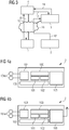
- Fig. 2 shows a monitoring system for a field device with Tamperschutz according to a second embodiment of the present invention.
- Fig. 2 a monitoring system according to Fig. 1
- the registration device 3 and the monitoring device 4 for the field device 1 are combined in a guide device 34.
- the field device 1 If the field device 1 has received a non-tampering assertion from the tamper monitoring device 2, the field device 1 transmits both field device data and the non-tampering assertion via the Internet 20 to the guide device 34.
- the guide device 34 first checks the non-tampering -Assertion that was transmitted from the field device 1. If this is valid, the transmitted field device data are accepted by the guide 34.
- Fig. 3 shows a monitoring system for a field device with Tamperschutz according to a third embodiment of the present invention.
- Fig. 3 essentially shows a monitoring system according to Fig. 1 , Unlike the surveillance system of Fig. 1 transmits the Tamperüberwachungs worn 2, as far as it has detected a physical manipulation of the field device 1, the non-tampering assertion not to the field device 1, but directly to the registration device 3, via the Internet 20, as in Fig. 3 shown. But it is also possible to use the non-tampering assertion via WLAN, according to Figures 1-5 via a mobile network, in particular GSM, UMTS, LTE, Wimax, CDMA or the like.
- a mobile network in particular GSM, UMTS, LTE, Wimax, CDMA or the like.
- the advantage thus achieved is that the field device does not have to be modified thereby, but the tamper monitoring device 2 can communicate with the registration device 3 independently of the field device 1, so that no interface for communication with the tamper monitoring device 2 has to be provided on the field device 1.
- Fig. 4a, 4b show tamper monitoring devices according to a first and a second embodiment.
- Reference numeral 2 denotes a tamper monitoring device, respectively.
- the respective tamper monitoring device 2 comprises a control computer 100, which is connected to a flash memory 101 and a RAM memory 102.
- the flash memory 101 serves as a configuration memory for the tamper monitoring device, while the RAM memory 102 serves as a working memory for the control computer 100.
- a power supply 103 is arranged, which is preferably designed such that, for example, the power supply 103 is battery-buffered or formed as a supercap, or this can provide energy by means of energy harvesting to use, for example, in power outages, the ambient temperature, vibration or air vibrations and so a continuous monitoring a field device 1 to allow.
- the respective Tamperüberwachungs worn 2 can be operated reliably.
- the respective tamper monitoring device 2 in each case comprises an input / output device 104, which are connected to sensors 104a for tamper monitoring.
- the sensors 104a are arranged in particular outside the housing of the respective tamper monitoring device 2.
- the respective tamper monitoring device 2 since it is designed for the specific task of tamper monitoring of the field device 1, can be optimized in terms of its energy consumption for this purpose.
- the control computer 100 can be in a so-called sleep mode, for example, for the majority of the time. If a tamper event is detected by the tamper monitoring device 2, the control computer 100 is reactivated.
- the tamper monitoring device 2 monitors by means of the sensors 104a, whether a tampering, that is, a physical manipulation of the field device 1 takes place.
- the sensors can be designed, for example, as motion sensors, light sensors, contacts, wire mesh or the like.
- the non-tampering assertion can be designed, for example, as a data structure which contains an identification number of the tamper monitoring device 2 and a time indication and / or a counter value.
- the data structure can be encrypted and provided with a cryptographic checksum, for example in the form of a digital signature or a message authentication code.
- the cryptographic checksum can be calculated by means of a cryptographic key stored on the tamper monitoring device 2 and provided by means of the interface 105.
- the interface 105 is in Fig. 4a wired, whereas in Fig. 4b is designed wirelessly.
- a non-tampering assertion can also contain at least one of the following information: identification information of the tamper monitoring device 2, additional information about the field device 1, which is monitored by the tamper monitoring device 2, a status of the field device 1, information about a physical manipulation, for example an indication of a housing opening a temperature at too high a temperature difference or the like, further a time information and / or a signature for authentication and integrity assurance.
- Fig. 5 shows a method for monitoring a tamper protection of a field device according to a first embodiment of the present invention.
- Reference numeral S1 denotes the step of checking whether manipulation has been performed on the field device 1
- reference numeral S2 indicates the step of issuing a non-manipulation certificate if a negative verification result has been detected
- reference numeral S3 indicates the step of transmitting the non-manipulation certificate
- reference numeral S4 the step of verifying the non-manipulation certificate by a registration device
- reference symbol S5 the step determining an active status of the field device by the registration device 3
- reference numeral S6 the step verifying the field device 1 by a monitoring device by transmitting the status of the field device 1 and reference symbol S7
- the step of transmitting field device data to the monitoring device 4 and reference symbol S8 the step of accepting the field device data by the monitoring device 4 as an active status, if an active Status of the field device 1 is present.
- the tamper monitoring device can be designed, for example, as a separate device, which is arranged in the field device to be monitored or a plurality of field devices to be monitored.
- the tamper monitoring device can be designed as a so-called intermediate unit, that is to say between the field device to be monitored and a fixed arrangement, for example a wall, a rail or the like.
- the tamper monitoring device can be embodied in a separate, additional housing, for example for a printed circuit board. It is also possible to install or integrate the tamper monitoring device and the sensors, which may be present for a tamper monitoring device, into the field device to be monitored itself.
- non-tampering certificate in the specification and in particular in the claims is to be understood as meaning not only a non-tampering acknowledgment message or a non-tampering assertion but also a message indicating that a physical manipulation of the monitored one Field device has taken place. If a physical manipulation is detected, a tampering certificate can be issued if a positive verification result has been determined. To be able to process this in the sense of the invention, in particular as shown in the claims and in the description of the figures, the field device, monitoring device and the registration device can be designed accordingly.
- the registration device can be further configured so that it is connected to a certification authority.
- the certification authority can provide the registration facility with a certificate revocation list or certificate revocation list in which a field device certificate of the field device monitored by the tamper monitoring device is listed.
- the field device certificate may be returned by an online certificate status protocol recipient or Online Certificate Status Protocol Responder. This allows an online transmission of the certificate cancellation list.
Landscapes
- Engineering & Computer Science (AREA)
- Computer Hardware Design (AREA)
- Theoretical Computer Science (AREA)
- Physics & Mathematics (AREA)
- General Physics & Mathematics (AREA)
- Computer Security & Cryptography (AREA)
- Software Systems (AREA)
- General Engineering & Computer Science (AREA)
- Automation & Control Theory (AREA)
- Alarm Systems (AREA)
Applications Claiming Priority (2)
| Application Number | Priority Date | Filing Date | Title |
|---|---|---|---|
| DE201110007572 DE102011007572A1 (de) | 2011-04-18 | 2011-04-18 | Verfahren zur Überwachung eines Tamperschutzes sowie Überwachungssystem für ein Feldgerät mit Tamperschutz |
| PCT/EP2012/056517 WO2012143271A1 (de) | 2011-04-18 | 2012-04-11 | Verfahren zur überwachung eines tamperschutzes sowie überwachungssystem für ein feldgerät mit tamperschutz |
Publications (2)
| Publication Number | Publication Date |
|---|---|
| EP2668607A1 EP2668607A1 (de) | 2013-12-04 |
| EP2668607B1 true EP2668607B1 (de) | 2018-04-04 |
Family
ID=46017820
Family Applications (1)
| Application Number | Title | Priority Date | Filing Date |
|---|---|---|---|
| EP12717242.7A Active EP2668607B1 (de) | 2011-04-18 | 2012-04-11 | Verfahren zur überwachung eines tamperschutzes sowie überwachungssystem für ein feldgerät mit tamperschutz |
Country Status (5)
| Country | Link |
|---|---|
| US (1) | US9147088B2 (es) |
| EP (1) | EP2668607B1 (es) |
| DE (1) | DE102011007572A1 (es) |
| ES (1) | ES2674923T3 (es) |
| WO (1) | WO2012143271A1 (es) |
Families Citing this family (50)
| Publication number | Priority date | Publication date | Assignee | Title |
|---|---|---|---|---|
| US20140297206A1 (en) * | 2013-03-28 | 2014-10-02 | Kaspar Llc | Universal Smart Energy Transformer Module |
| AU2015296645A1 (en) | 2014-07-28 | 2017-02-16 | Econolite Group, Inc. | Self-configuring traffic signal controller |
| CN105282518A (zh) * | 2015-11-12 | 2016-01-27 | 国家电网公司 | 自动获取事故变电站视频画面系统 |
| DE102016200850A1 (de) | 2016-01-21 | 2017-07-27 | Siemens Aktiengesellschaft | Verfahren zum Betreiben einer sicherheitsrelevanten Vorrichtung und Vorrichtung |
| DE102016200907A1 (de) | 2016-01-22 | 2017-07-27 | Siemens Aktiengesellschaft | Verfahren zum Betreiben einer sicherheitsrelevanten Vorrichtung und Vorrichtung |
| DE102016201176A1 (de) | 2016-01-27 | 2017-07-27 | Siemens Aktiengesellschaft | Verfahren und Vorrichtung zum Erzeugen von Zufallsbits |
| MX2017013621A (es) | 2016-02-09 | 2018-03-08 | Siemens Ag | Metodo y entorno de ejecucion para ejecutar instrucciones de programa de forma segura. |
| DE102016203534A1 (de) | 2016-03-03 | 2017-09-07 | Siemens Aktiengesellschaft | Verfahren und Analysemodul zur Überprüfung von verschlüsselten Datenübertragungen |
| DE102016205289A1 (de) | 2016-03-31 | 2017-10-05 | Siemens Aktiengesellschaft | Verfahren, Prozessor und Gerät zur Integritätsprüfung von Nutzerdaten |
| DE102016207294A1 (de) | 2016-04-28 | 2017-11-02 | Siemens Aktiengesellschaft | Verfahren und Zertifikatspeicher zur Zertifikatsverwaltung |
| DE102016207635A1 (de) | 2016-05-03 | 2017-11-09 | Siemens Aktiengesellschaft | Verfahren und Vorrichtung zur Absicherung von Gerätezugriffen |
| DE102016207642A1 (de) | 2016-05-03 | 2017-11-09 | Siemens Aktiengesellschaft | Verfahren und Vorrichtungen zum Authentisieren eines Datenstroms |
| EP3252990A1 (de) | 2016-06-03 | 2017-12-06 | Siemens Aktiengesellschaft | Verfahren und vorrichtung zum bereitstellen eines geheimnisses zum authentisieren eines systems und/oder komponenten des systems |
| DE102016219926A1 (de) | 2016-10-13 | 2018-04-19 | Siemens Aktiengesellschaft | Verfahren, Sender und Empfänger zum Authentisieren und zum Integritätsschutz von Nachrichteninhalten |
| DE102016221301A1 (de) | 2016-10-28 | 2018-05-03 | Siemens Aktiengesellschaft | Verfahren und Geräte zum Bereitstellen einer Senderidentifizierungsnachricht für einen Sender |
| DE102017102677A1 (de) * | 2017-02-10 | 2018-08-16 | Endress+Hauser Conducta Gmbh+Co. Kg | Verfahren zur Authentifizierung eines Feldgeräts der Automatisierungstechnik |
| EP3413530B1 (de) | 2017-06-09 | 2019-07-31 | Siemens Aktiengesellschaft | Verfahren und vorrichtung zum austauschen von nachrichten |
| EP3435272B1 (de) | 2017-07-27 | 2020-11-04 | Siemens Aktiengesellschaft | Verfahren und vorrichtung zur identifikation eines additiv gefertigten werkstücks |
| DE102017223099A1 (de) | 2017-12-18 | 2019-06-19 | Siemens Aktiengesellschaft | Vorrichtung und Verfahren zum Übertragen von Daten zwischen einem ersten und einem zweiten Netzwerk |
| EP3502806A1 (de) | 2017-12-22 | 2019-06-26 | Siemens Aktiengesellschaft | Verfahren zum schutz der produktionsdaten zur herstellung eines produkts |
| EP3503493A1 (de) | 2017-12-22 | 2019-06-26 | Siemens Aktiengesellschaft | Kommunikationsvorrichtung und verfahren zum verarbeiten eines netzwerkpakets |
| EP3506143B1 (en) | 2017-12-27 | 2024-02-14 | Siemens Aktiengesellschaft | Interface for a hardware security module |
| EP3509247A1 (de) | 2018-01-03 | 2019-07-10 | Siemens Aktiengesellschaft | Verfahren und schlüsselgenerator zum rechnergestützten erzeugen eines gesamtschlüssels |
| EP3509004A1 (en) | 2018-01-03 | 2019-07-10 | Siemens Aktiengesellschaft | Adaption of mac policies in industrial devices |
| EP3514743A1 (en) | 2018-01-22 | 2019-07-24 | Siemens Aktiengesellschaft | Device and method for providing instruction data for manufacturing an individualized product |
| EP3534282A1 (de) | 2018-03-01 | 2019-09-04 | Siemens Aktiengesellschaft | Verfahren und sicherheitsmodul zum rechnergestützten ausführen von programmcode |
| EP3557463B1 (de) | 2018-04-16 | 2020-10-21 | Siemens Aktiengesellschaft | Verfahren und ausführungsumgebung zum ausführen von programmcode auf einem steuergerät |
| EP3562194B1 (en) | 2018-04-23 | 2021-07-28 | Siemens Aktiengesellschaft | Method for identifying at least one network slice configuration of a mobile network, communication system, and automation system |
| EP3561709B1 (en) | 2018-04-25 | 2020-07-29 | Siemens Aktiengesellschaft | Data processing apparatus, system, and method for proving or checking the security of a data processing apparatus |
| EP3562090B1 (en) | 2018-04-25 | 2020-07-01 | Siemens Aktiengesellschaft | Data processing device for processing a radio signal |
| EP3561713B1 (en) | 2018-04-25 | 2022-07-13 | Siemens Aktiengesellschaft | Retrieval device for authentication information, system and method for secure authentication |
| EP3562116A1 (en) | 2018-04-26 | 2019-10-30 | Siemens Aktiengesellschaft | Cryptographic key exchange or key agreement involving a device without network access |
| EP3570489B1 (en) | 2018-05-18 | 2020-04-08 | Siemens Aktiengesellschaft | Device and method for transforming blockchain data blocks |
| DK3584654T3 (da) | 2018-06-19 | 2020-08-10 | Siemens Ag | Hierarkisk fordelt ledger |
| EP3598364A1 (en) | 2018-07-17 | 2020-01-22 | Siemens Aktiengesellschaft | Timing constraint for transactions of a distributed database system |
| EP3598363A1 (en) | 2018-07-17 | 2020-01-22 | Siemens Aktiengesellschaft | Resource reservation for transactions of a distributed database system |
| EP3598365A1 (en) | 2018-07-17 | 2020-01-22 | Siemens Aktiengesellschaft | Traffic shaping for transactions of a distributed database system |
| EP3599740A1 (de) | 2018-07-25 | 2020-01-29 | Siemens Aktiengesellschaft | Steuern eines datennetzes hinsichtlich eines einsatzes einer verteilten datenbank |
| EP3609148A1 (de) | 2018-08-06 | 2020-02-12 | Siemens Aktiengesellschaft | Verfahren und netzwerkknoten zur verarbeitung von messdaten |
| EP3609240A1 (de) | 2018-08-09 | 2020-02-12 | Siemens Aktiengesellschaft | Computerimplementiertes verfahren und netzwerkzugangsserver zum verbinden einer netzwerkkomponente mit einem netzwerk, insbesondere einem mobilfunknetz, mit einem erweiterten netzwerkzugangskennzeichen |
| EP3614319A1 (en) | 2018-08-20 | 2020-02-26 | Siemens Aktiengesellschaft | Tracking execution of an industrial workflow of a petri net |
| EP3629332A1 (de) | 2018-09-28 | 2020-04-01 | Siemens Aktiengesellschaft | Sicheres ausgeben einer substanz |
| EP3633914A1 (de) | 2018-10-05 | 2020-04-08 | Siemens Aktiengesellschaft | Verfahren und system zur nachweisbaren datenverarbeitung unter anwendung von obfuskation |
| EP3637345A1 (de) | 2018-10-10 | 2020-04-15 | Siemens Aktiengesellschaft | Verknüpfung von identitäten in einer verteilten datenbank |
| EP3687209A1 (en) | 2019-01-25 | 2020-07-29 | Siemens Aktiengesellschaft | Secure multi-hop communication paths |
| EP3693918A1 (en) | 2019-02-08 | 2020-08-12 | Siemens Gamesa Renewable Energy A/S | Operational data of an energy system |
| EP3736715A1 (en) | 2019-05-10 | 2020-11-11 | Siemens Aktiengesellschaft | Managing admission to a distributed database based on a consensus process |
| CN111027109A (zh) * | 2019-11-15 | 2020-04-17 | 深圳中电长城信息安全系统有限公司 | 产品安全监控方法、装置及系统 |
| US11899831B2 (en) | 2021-09-15 | 2024-02-13 | Hewlett Packard Enterprise Development Lp | Managing security of enclosure based on a task status and geographical location of the enclosure |
| DE102022127499B3 (de) | 2022-10-19 | 2024-01-25 | Cariad Se | Kraftfahrzeug, Steuergerät und Verfahren zur Intrusionserkennung eines Steuergerätegehäuses eines Steuergerätes |
Family Cites Families (11)
| Publication number | Priority date | Publication date | Assignee | Title |
|---|---|---|---|---|
| US8549310B2 (en) * | 1996-04-08 | 2013-10-01 | Walker Digital, Llc | Method and apparatus for secure measurement certification |
| US6357007B1 (en) | 1998-07-01 | 2002-03-12 | International Business Machines Corporation | System for detecting tamper events and capturing the time of their occurrence |
| FR2826531B1 (fr) * | 2001-06-26 | 2003-10-24 | France Telecom | Procede cryptographique pour la protection d'une puce electronique contre la fraude |
| DE10238093B4 (de) * | 2002-08-21 | 2007-10-18 | Audi Ag | Fahrzeug-Steuergerät |
| DE602004030426D1 (de) | 2003-03-06 | 2011-01-20 | Cypak Ab | Verpackung mit originalitätssicherung |
| DE10339349A1 (de) * | 2003-08-25 | 2005-03-24 | Endress + Hauser Process Solutions Ag | Eingabeeinheit für die Prozessautomatisierungstechnik |
| DE102004017529A1 (de) | 2004-04-08 | 2005-11-03 | Siemens Ag | Automatisierungsnetzwerk sowie Automatisierungsgerät, Netzwerkkomponente und Feldgerät für ein derartiges Netzwerk |
| DE102004043052B3 (de) * | 2004-09-06 | 2006-01-19 | Siemens Ag | Verfahren zur Manipulationserkennung an einer Anordnung mit einem Sensor |
| US20070255966A1 (en) * | 2006-05-01 | 2007-11-01 | Vincenzo Condorelli | Cryptographic circuit with voltage-based tamper detection and response circuitry |
| US7945792B2 (en) * | 2007-10-17 | 2011-05-17 | Spansion Llc | Tamper reactive memory device to secure data from tamper attacks |
| US8188860B2 (en) * | 2007-10-22 | 2012-05-29 | Infineon Technologies Ag | Secure sensor/actuator systems |
-
2011
- 2011-04-18 DE DE201110007572 patent/DE102011007572A1/de not_active Withdrawn
-
2012
- 2012-04-11 US US14/112,534 patent/US9147088B2/en active Active
- 2012-04-11 ES ES12717242.7T patent/ES2674923T3/es active Active
- 2012-04-11 EP EP12717242.7A patent/EP2668607B1/de active Active
- 2012-04-11 WO PCT/EP2012/056517 patent/WO2012143271A1/de active Application Filing
Also Published As
| Publication number | Publication date |
|---|---|
| US20140047568A1 (en) | 2014-02-13 |
| EP2668607A1 (de) | 2013-12-04 |
| DE102011007572A1 (de) | 2012-10-18 |
| ES2674923T3 (es) | 2018-07-05 |
| US9147088B2 (en) | 2015-09-29 |
| WO2012143271A1 (de) | 2012-10-26 |
Similar Documents
| Publication | Publication Date | Title |
|---|---|---|
| EP2668607B1 (de) | Verfahren zur überwachung eines tamperschutzes sowie überwachungssystem für ein feldgerät mit tamperschutz | |
| EP2628121B1 (de) | Vorrichtung und verfahren zum schutz eines sicherheitsmoduls gegen manipulationsversuche in einem feldgerät | |
| EP3207683A1 (de) | Verfahren und vorrichtung zum rückwirkungsfreien erfassen von daten | |
| EP2586178B1 (de) | Verfahren zur manipulationsgesicherten schlüsselverwaltung | |
| WO2020212051A1 (de) | Industrielles automatisierungsgerät umfassend eine überwachungseinheit zur überprüfung und überwachung eines integritätszustandes des industriellen automatisierungsgerätes | |
| WO2019034338A1 (de) | Vorrichtung und verfahren zum detektieren von unbefugten änderungen an einer automatisierungskomponente | |
| EP2666117B1 (de) | Verfahren zum prüfen eines tamperschutzes eines feldgeräts sowie feldgerät mit tamperschutz | |
| CN203271342U (zh) | 一种物联网密码锁 | |
| DE102010021256A1 (de) | Verfahren zur dynamischen Autorisierung eines mobilen Kommunikationsgerätes | |
| EP2376871B1 (de) | Verfahren zum betreiben einer sensorvorrichtung und sensorvorrichtung | |
| DE102010028152B4 (de) | Aufzeichnung von History-Informationen in einem Feldgerät | |
| EP2054782B1 (de) | Datenaufnahmevorrichtung | |
| DE102019125087A1 (de) | Vorrichtung und Verfahren zur Identifikation und Zustandsüberwachung einer zu überwachenden Einrichtung mit einem öffenbaren und verschließbaren Flügelelement | |
| DE102019212065A1 (de) | Verfahren zum Protokollieren einer Verwendungshistorie eines Batteriesystems sowie Batteriesystem und Kraftfahrzeug | |
| EP2673733B1 (de) | Tamperschutzvorrichtung zum tamperschutz eines feldgeräts | |
| DE102012213155A1 (de) | Vorrichtung mit Sicherheitseinheiten in unterschiedlich geschützten Bereichen | |
| DE102014207810A1 (de) | Verfahren und Vorrichtung zum Betreiben eines Kraftfahrzeugs | |
| DE102021126959A1 (de) | Zusatzmodul für Manipulationsschutz eines Sensors | |
| JP6558942B2 (ja) | ラック管理システム | |
| DE102021114559A1 (de) | Zugriffsicheres Feldgerät | |
| EP3401831A1 (de) | Vorrichtung und verfahren zum erkennen einer physikalischen manipulation an einem elektronischen sicherheitsmodul | |
| DE102020133063A1 (de) | Verfahren zur Überwachung eines Feldgeräts und Feldgerätt | |
| WO2021223855A1 (de) | Erweiterungsmodul mit manipulationsschutz | |
| DE102022130426A1 (de) | Verfahren und System zum Dokumentieren von Logbuchdaten von einem oder mehreren ersten Feldgeräten | |
| EP4044551A1 (de) | Überwachung einer vertrauenswürdigkeit einer registrierungsstelle |
Legal Events
| Date | Code | Title | Description |
|---|---|---|---|
| PUAI | Public reference made under article 153(3) epc to a published international application that has entered the european phase |
Free format text: ORIGINAL CODE: 0009012 |
|
| 17P | Request for examination filed |
Effective date: 20130827 |
|
| AK | Designated contracting states |
Kind code of ref document: A1 Designated state(s): AL AT BE BG CH CY CZ DE DK EE ES FI FR GB GR HR HU IE IS IT LI LT LU LV MC MK MT NL NO PL PT RO RS SE SI SK SM TR |
|
| DAX | Request for extension of the european patent (deleted) | ||
| RAP1 | Party data changed (applicant data changed or rights of an application transferred) |
Owner name: SIEMENS AKTIENGESELLSCHAFT |
|
| REG | Reference to a national code |
Ref country code: DE Ref legal event code: R079 Ref document number: 502012012485 Country of ref document: DE Free format text: PREVIOUS MAIN CLASS: G06F0021060000 Ipc: G05B0019042000 |
|
| GRAP | Despatch of communication of intention to grant a patent |
Free format text: ORIGINAL CODE: EPIDOSNIGR1 |
|
| RIC1 | Information provided on ipc code assigned before grant |
Ipc: G06F 21/86 20130101ALI20171020BHEP Ipc: G05B 19/042 20060101AFI20171020BHEP |
|
| INTG | Intention to grant announced |
Effective date: 20171107 |
|
| GRAS | Grant fee paid |
Free format text: ORIGINAL CODE: EPIDOSNIGR3 |
|
| GRAA | (expected) grant |
Free format text: ORIGINAL CODE: 0009210 |
|
| AK | Designated contracting states |
Kind code of ref document: B1 Designated state(s): AL AT BE BG CH CY CZ DE DK EE ES FI FR GB GR HR HU IE IS IT LI LT LU LV MC MK MT NL NO PL PT RO RS SE SI SK SM TR |
|
| REG | Reference to a national code |
Ref country code: GB Ref legal event code: FG4D Free format text: NOT ENGLISH |
|
| REG | Reference to a national code |
Ref country code: FR Ref legal event code: PLFP Year of fee payment: 7 |
|
| REG | Reference to a national code |
Ref country code: CH Ref legal event code: EP |
|
| REG | Reference to a national code |
Ref country code: AT Ref legal event code: REF Ref document number: 986236 Country of ref document: AT Kind code of ref document: T Effective date: 20180415 |
|
| REG | Reference to a national code |
Ref country code: DE Ref legal event code: R096 Ref document number: 502012012485 Country of ref document: DE |
|
| REG | Reference to a national code |
Ref country code: IE Ref legal event code: FG4D Free format text: LANGUAGE OF EP DOCUMENT: GERMAN |
|
| REG | Reference to a national code |
Ref country code: CH Ref legal event code: NV Representative=s name: SIEMENS SCHWEIZ AG, CH |
|
| REG | Reference to a national code |
Ref country code: ES Ref legal event code: FG2A Ref document number: 2674923 Country of ref document: ES Kind code of ref document: T3 Effective date: 20180705 |
|
| REG | Reference to a national code |
Ref country code: NL Ref legal event code: MP Effective date: 20180404 |
|
| REG | Reference to a national code |
Ref country code: LT Ref legal event code: MG4D |
|
| PG25 | Lapsed in a contracting state [announced via postgrant information from national office to epo] |
Ref country code: NL Free format text: LAPSE BECAUSE OF FAILURE TO SUBMIT A TRANSLATION OF THE DESCRIPTION OR TO PAY THE FEE WITHIN THE PRESCRIBED TIME-LIMIT Effective date: 20180404 |
|
| PG25 | Lapsed in a contracting state [announced via postgrant information from national office to epo] |
Ref country code: SE Free format text: LAPSE BECAUSE OF FAILURE TO SUBMIT A TRANSLATION OF THE DESCRIPTION OR TO PAY THE FEE WITHIN THE PRESCRIBED TIME-LIMIT Effective date: 20180404 Ref country code: PL Free format text: LAPSE BECAUSE OF FAILURE TO SUBMIT A TRANSLATION OF THE DESCRIPTION OR TO PAY THE FEE WITHIN THE PRESCRIBED TIME-LIMIT Effective date: 20180404 Ref country code: LT Free format text: LAPSE BECAUSE OF FAILURE TO SUBMIT A TRANSLATION OF THE DESCRIPTION OR TO PAY THE FEE WITHIN THE PRESCRIBED TIME-LIMIT Effective date: 20180404 Ref country code: BG Free format text: LAPSE BECAUSE OF FAILURE TO SUBMIT A TRANSLATION OF THE DESCRIPTION OR TO PAY THE FEE WITHIN THE PRESCRIBED TIME-LIMIT Effective date: 20180704 Ref country code: AL Free format text: LAPSE BECAUSE OF FAILURE TO SUBMIT A TRANSLATION OF THE DESCRIPTION OR TO PAY THE FEE WITHIN THE PRESCRIBED TIME-LIMIT Effective date: 20180404 Ref country code: NO Free format text: LAPSE BECAUSE OF FAILURE TO SUBMIT A TRANSLATION OF THE DESCRIPTION OR TO PAY THE FEE WITHIN THE PRESCRIBED TIME-LIMIT Effective date: 20180704 Ref country code: FI Free format text: LAPSE BECAUSE OF FAILURE TO SUBMIT A TRANSLATION OF THE DESCRIPTION OR TO PAY THE FEE WITHIN THE PRESCRIBED TIME-LIMIT Effective date: 20180404 |
|
| PG25 | Lapsed in a contracting state [announced via postgrant information from national office to epo] |
Ref country code: GR Free format text: LAPSE BECAUSE OF FAILURE TO SUBMIT A TRANSLATION OF THE DESCRIPTION OR TO PAY THE FEE WITHIN THE PRESCRIBED TIME-LIMIT Effective date: 20180705 Ref country code: RS Free format text: LAPSE BECAUSE OF FAILURE TO SUBMIT A TRANSLATION OF THE DESCRIPTION OR TO PAY THE FEE WITHIN THE PRESCRIBED TIME-LIMIT Effective date: 20180404 Ref country code: LV Free format text: LAPSE BECAUSE OF FAILURE TO SUBMIT A TRANSLATION OF THE DESCRIPTION OR TO PAY THE FEE WITHIN THE PRESCRIBED TIME-LIMIT Effective date: 20180404 Ref country code: HR Free format text: LAPSE BECAUSE OF FAILURE TO SUBMIT A TRANSLATION OF THE DESCRIPTION OR TO PAY THE FEE WITHIN THE PRESCRIBED TIME-LIMIT Effective date: 20180404 |
|
| REG | Reference to a national code |
Ref country code: BE Ref legal event code: MM Effective date: 20180430 |
|
| PG25 | Lapsed in a contracting state [announced via postgrant information from national office to epo] |
Ref country code: PT Free format text: LAPSE BECAUSE OF FAILURE TO SUBMIT A TRANSLATION OF THE DESCRIPTION OR TO PAY THE FEE WITHIN THE PRESCRIBED TIME-LIMIT Effective date: 20180806 |
|
| REG | Reference to a national code |
Ref country code: DE Ref legal event code: R097 Ref document number: 502012012485 Country of ref document: DE |
|
| REG | Reference to a national code |
Ref country code: IE Ref legal event code: MM4A |
|
| PG25 | Lapsed in a contracting state [announced via postgrant information from national office to epo] |
Ref country code: SK Free format text: LAPSE BECAUSE OF FAILURE TO SUBMIT A TRANSLATION OF THE DESCRIPTION OR TO PAY THE FEE WITHIN THE PRESCRIBED TIME-LIMIT Effective date: 20180404 Ref country code: MC Free format text: LAPSE BECAUSE OF FAILURE TO SUBMIT A TRANSLATION OF THE DESCRIPTION OR TO PAY THE FEE WITHIN THE PRESCRIBED TIME-LIMIT Effective date: 20180404 Ref country code: LU Free format text: LAPSE BECAUSE OF NON-PAYMENT OF DUE FEES Effective date: 20180411 Ref country code: DK Free format text: LAPSE BECAUSE OF FAILURE TO SUBMIT A TRANSLATION OF THE DESCRIPTION OR TO PAY THE FEE WITHIN THE PRESCRIBED TIME-LIMIT Effective date: 20180404 Ref country code: CZ Free format text: LAPSE BECAUSE OF FAILURE TO SUBMIT A TRANSLATION OF THE DESCRIPTION OR TO PAY THE FEE WITHIN THE PRESCRIBED TIME-LIMIT Effective date: 20180404 Ref country code: RO Free format text: LAPSE BECAUSE OF FAILURE TO SUBMIT A TRANSLATION OF THE DESCRIPTION OR TO PAY THE FEE WITHIN THE PRESCRIBED TIME-LIMIT Effective date: 20180404 Ref country code: EE Free format text: LAPSE BECAUSE OF FAILURE TO SUBMIT A TRANSLATION OF THE DESCRIPTION OR TO PAY THE FEE WITHIN THE PRESCRIBED TIME-LIMIT Effective date: 20180404 |
|
| PLBE | No opposition filed within time limit |
Free format text: ORIGINAL CODE: 0009261 |
|
| STAA | Information on the status of an ep patent application or granted ep patent |
Free format text: STATUS: NO OPPOSITION FILED WITHIN TIME LIMIT |
|
| PG25 | Lapsed in a contracting state [announced via postgrant information from national office to epo] |
Ref country code: SM Free format text: LAPSE BECAUSE OF FAILURE TO SUBMIT A TRANSLATION OF THE DESCRIPTION OR TO PAY THE FEE WITHIN THE PRESCRIBED TIME-LIMIT Effective date: 20180404 Ref country code: BE Free format text: LAPSE BECAUSE OF NON-PAYMENT OF DUE FEES Effective date: 20180430 |
|
| 26N | No opposition filed |
Effective date: 20190107 |
|
| PG25 | Lapsed in a contracting state [announced via postgrant information from national office to epo] |
Ref country code: IE Free format text: LAPSE BECAUSE OF NON-PAYMENT OF DUE FEES Effective date: 20180411 |
|
| PG25 | Lapsed in a contracting state [announced via postgrant information from national office to epo] |
Ref country code: SI Free format text: LAPSE BECAUSE OF FAILURE TO SUBMIT A TRANSLATION OF THE DESCRIPTION OR TO PAY THE FEE WITHIN THE PRESCRIBED TIME-LIMIT Effective date: 20180404 |
|
| REG | Reference to a national code |
Ref country code: AT Ref legal event code: MM01 Ref document number: 986236 Country of ref document: AT Kind code of ref document: T Effective date: 20180411 |
|
| PG25 | Lapsed in a contracting state [announced via postgrant information from national office to epo] |
Ref country code: AT Free format text: LAPSE BECAUSE OF NON-PAYMENT OF DUE FEES Effective date: 20180411 |
|
| PGFP | Annual fee paid to national office [announced via postgrant information from national office to epo] |
Ref country code: ES Payment date: 20190725 Year of fee payment: 8 |
|
| PG25 | Lapsed in a contracting state [announced via postgrant information from national office to epo] |
Ref country code: MT Free format text: LAPSE BECAUSE OF FAILURE TO SUBMIT A TRANSLATION OF THE DESCRIPTION OR TO PAY THE FEE WITHIN THE PRESCRIBED TIME-LIMIT Effective date: 20180404 |
|
| PGFP | Annual fee paid to national office [announced via postgrant information from national office to epo] |
Ref country code: CH Payment date: 20190702 Year of fee payment: 8 |
|
| PG25 | Lapsed in a contracting state [announced via postgrant information from national office to epo] |
Ref country code: TR Free format text: LAPSE BECAUSE OF FAILURE TO SUBMIT A TRANSLATION OF THE DESCRIPTION OR TO PAY THE FEE WITHIN THE PRESCRIBED TIME-LIMIT Effective date: 20180404 |
|
| PG25 | Lapsed in a contracting state [announced via postgrant information from national office to epo] |
Ref country code: HU Free format text: LAPSE BECAUSE OF FAILURE TO SUBMIT A TRANSLATION OF THE DESCRIPTION OR TO PAY THE FEE WITHIN THE PRESCRIBED TIME-LIMIT; INVALID AB INITIO Effective date: 20120411 |
|
| PG25 | Lapsed in a contracting state [announced via postgrant information from national office to epo] |
Ref country code: CY Free format text: LAPSE BECAUSE OF FAILURE TO SUBMIT A TRANSLATION OF THE DESCRIPTION OR TO PAY THE FEE WITHIN THE PRESCRIBED TIME-LIMIT Effective date: 20180404 Ref country code: MK Free format text: LAPSE BECAUSE OF NON-PAYMENT OF DUE FEES Effective date: 20180404 |
|
| PG25 | Lapsed in a contracting state [announced via postgrant information from national office to epo] |
Ref country code: IS Free format text: LAPSE BECAUSE OF FAILURE TO SUBMIT A TRANSLATION OF THE DESCRIPTION OR TO PAY THE FEE WITHIN THE PRESCRIBED TIME-LIMIT Effective date: 20180804 |
|
| PGFP | Annual fee paid to national office [announced via postgrant information from national office to epo] |
Ref country code: GB Payment date: 20200402 Year of fee payment: 9 |
|
| REG | Reference to a national code |
Ref country code: CH Ref legal event code: PL |
|
| PG25 | Lapsed in a contracting state [announced via postgrant information from national office to epo] |
Ref country code: LI Free format text: LAPSE BECAUSE OF NON-PAYMENT OF DUE FEES Effective date: 20200430 Ref country code: CH Free format text: LAPSE BECAUSE OF NON-PAYMENT OF DUE FEES Effective date: 20200430 |
|
| REG | Reference to a national code |
Ref country code: ES Ref legal event code: FD2A Effective date: 20210831 |
|
| PG25 | Lapsed in a contracting state [announced via postgrant information from national office to epo] |
Ref country code: ES Free format text: LAPSE BECAUSE OF NON-PAYMENT OF DUE FEES Effective date: 20200412 |
|
| GBPC | Gb: european patent ceased through non-payment of renewal fee |
Effective date: 20210411 |
|
| PG25 | Lapsed in a contracting state [announced via postgrant information from national office to epo] |
Ref country code: GB Free format text: LAPSE BECAUSE OF NON-PAYMENT OF DUE FEES Effective date: 20210411 |
|
| PGFP | Annual fee paid to national office [announced via postgrant information from national office to epo] |
Ref country code: IT Payment date: 20230421 Year of fee payment: 12 Ref country code: DE Payment date: 20220620 Year of fee payment: 12 |
|
| PGFP | Annual fee paid to national office [announced via postgrant information from national office to epo] |
Ref country code: FR Payment date: 20230905 Year of fee payment: 13 |