EP2668607B1 - Method for monitoring a tamper protection and monitoring system for a field device having tamper protection - Google Patents
Method for monitoring a tamper protection and monitoring system for a field device having tamper protection Download PDFInfo
- Publication number
- EP2668607B1 EP2668607B1 EP12717242.7A EP12717242A EP2668607B1 EP 2668607 B1 EP2668607 B1 EP 2668607B1 EP 12717242 A EP12717242 A EP 12717242A EP 2668607 B1 EP2668607 B1 EP 2668607B1
- Authority
- EP
- European Patent Office
- Prior art keywords
- field device
- monitoring
- manipulation
- certificate
- tamper
- Prior art date
- Legal status (The legal status is an assumption and is not a legal conclusion. Google has not performed a legal analysis and makes no representation as to the accuracy of the status listed.)
- Active
Links
- 238000012544 monitoring process Methods 0.000 title claims description 46
- 238000000034 method Methods 0.000 title claims description 16
- 238000012806 monitoring device Methods 0.000 claims description 71
- 238000004891 communication Methods 0.000 claims description 7
- 238000009434 installation Methods 0.000 claims 1
- 230000005540 biological transmission Effects 0.000 description 14
- 230000015654 memory Effects 0.000 description 7
- 238000012795 verification Methods 0.000 description 5
- 238000004519 manufacturing process Methods 0.000 description 3
- 239000002184 metal Substances 0.000 description 2
- 230000001960 triggered effect Effects 0.000 description 2
- 208000033748 Device issues Diseases 0.000 description 1
- 239000003990 capacitor Substances 0.000 description 1
- 238000011161 development Methods 0.000 description 1
- 230000018109 developmental process Effects 0.000 description 1
- 238000005265 energy consumption Methods 0.000 description 1
- 238000003306 harvesting Methods 0.000 description 1
- 238000004806 packaging method and process Methods 0.000 description 1
- 230000011664 signaling Effects 0.000 description 1
- 238000012800 visualization Methods 0.000 description 1
- 230000003936 working memory Effects 0.000 description 1
Images


Classifications
-
- G—PHYSICS
- G06—COMPUTING; CALCULATING OR COUNTING
- G06F—ELECTRIC DIGITAL DATA PROCESSING
- G06F21/00—Security arrangements for protecting computers, components thereof, programs or data against unauthorised activity
- G06F21/70—Protecting specific internal or peripheral components, in which the protection of a component leads to protection of the entire computer
- G06F21/86—Secure or tamper-resistant housings
-
- G—PHYSICS
- G05—CONTROLLING; REGULATING
- G05B—CONTROL OR REGULATING SYSTEMS IN GENERAL; FUNCTIONAL ELEMENTS OF SUCH SYSTEMS; MONITORING OR TESTING ARRANGEMENTS FOR SUCH SYSTEMS OR ELEMENTS
- G05B19/00—Programme-control systems
- G05B19/02—Programme-control systems electric
- G05B19/04—Programme control other than numerical control, i.e. in sequence controllers or logic controllers
- G05B19/042—Programme control other than numerical control, i.e. in sequence controllers or logic controllers using digital processors
- G05B19/0423—Input/output
- G05B19/0425—Safety, monitoring
-
- G—PHYSICS
- G05—CONTROLLING; REGULATING
- G05B—CONTROL OR REGULATING SYSTEMS IN GENERAL; FUNCTIONAL ELEMENTS OF SUCH SYSTEMS; MONITORING OR TESTING ARRANGEMENTS FOR SUCH SYSTEMS OR ELEMENTS
- G05B2219/00—Program-control systems
- G05B2219/30—Nc systems
- G05B2219/37—Measurements
- G05B2219/37038—Protection cover over measuring device, probe, feeler opened when measuring
-
- Y—GENERAL TAGGING OF NEW TECHNOLOGICAL DEVELOPMENTS; GENERAL TAGGING OF CROSS-SECTIONAL TECHNOLOGIES SPANNING OVER SEVERAL SECTIONS OF THE IPC; TECHNICAL SUBJECTS COVERED BY FORMER USPC CROSS-REFERENCE ART COLLECTIONS [XRACs] AND DIGESTS
- Y04—INFORMATION OR COMMUNICATION TECHNOLOGIES HAVING AN IMPACT ON OTHER TECHNOLOGY AREAS
- Y04S—SYSTEMS INTEGRATING TECHNOLOGIES RELATED TO POWER NETWORK OPERATION, COMMUNICATION OR INFORMATION TECHNOLOGIES FOR IMPROVING THE ELECTRICAL POWER GENERATION, TRANSMISSION, DISTRIBUTION, MANAGEMENT OR USAGE, i.e. SMART GRIDS
- Y04S40/00—Systems for electrical power generation, transmission, distribution or end-user application management characterised by the use of communication or information technologies, or communication or information technology specific aspects supporting them
- Y04S40/20—Information technology specific aspects, e.g. CAD, simulation, modelling, system security
Definitions
- the invention relates to a method for monitoring a tamper protection, a monitoring system for a field device with tamper protection and a use of a monitoring system.
- Field devices for example in the form of traffic sign systems for traffic control, signaling systems for trains, switches, etc., are usually connected to a control center or a signal box for their operation and monitoring.
- the communication between field device and control center can be done either wired by means of appropriately routed cable or wirelessly through a radio link.
- sensors for example motion sensors
- corresponding sensors for example motion sensors
- corresponding sensors for example motion sensors
- hardware security integrated circuits which can store cryptographic keys and perform cryptographic operations.
- integrated circuits usually have a tamper protection, for example in the form of sensors arranged directly on the integrated circuit. These are designed to detect unauthorized opening of the integrated circuit.
- Such a hardware security integrated circuit has become known, for example, as a "Trusted Platform Module” whose data can be called up at http://de.wikipedia.org/wiki/trusted_platform_module.
- Such integrated circuits are installed, for example, in PCs or notebooks.
- An object of the present invention is to provide a method for monitoring a tamper protection of a field device and a monitoring system for a field device with tamper protection, in which tamper protection is made simple and inexpensive. At the same time they should be flexible and adaptable for a variety of different devices easily and inexpensively and adaptable provide the desired level of security against physical manipulation.
- a method for monitoring a tamper protection of a field device comprising the steps of checking whether a tampering has been performed on the field device, issuing a non-tamper certificate, if a negative verification result has been determined, transmitting the tamper certificate Verifying the non-manipulation certificate by a registration device, setting the active state of the field device by the registration device, if the non-tampering certificate is valid, checking the field device by a monitoring device by querying the status of the field device and transmitting field device data to the Monitoring device, accepting the field device data by the monitoring device, if there is an active status of the field device.
- a monitoring system for a field device with tamper protection in particular suitable for carrying out a method according to at least one of claims 1-5, comprising a tamper monitoring device, which is designed to monitor the field device for tamper protection, a registration device for registering and Status monitoring of the field device, a monitoring device for controlling and monitoring the field device, wherein the Tamperüberwachungs recruited is adapted to check whether a manipulation has been done on the field device and outputs a non-manipulation certificate, if a negative verification result has been determined, and wherein the registration device is configured to check the non-tampering certificate, and to set an active status of the field device with a valid non-tampering certificate, and wherein the monitoring device is configured to generate a St At the field device to check, and wherein the monitoring device is formed, field device data if there is an active status of the field device.
- This object is also achieved by the use of a monitoring system according to at least one of claims 6-10 for monitoring a traffic system or for monitoring a substation.
- An advantage achieved with this is that a tamper protection can be retrofitted in a simple manner and without much effort especially in the case of existing field devices.
- a further advantage is that the field devices to be monitored can be developed and manufactured without specially trained tamper protection measures having to be taken into account in the field device itself.
- the method for monitoring the tamper protection also blocks only the field device and / or a security key stored in the field device so that any data read out from a memory of the field device, in particular the possibly read-out security key, can not be used by an attacker.
- Another advantage is that such tamper protection monitoring can be used for many different types of field devices, which significantly reduces manufacturing costs for the respective field devices. Tamper protection only has to be developed once and not separately for each field device type. In addition, a direct communication between the Tamperschutzplatzwachungsvorraum and the field device is not needed. This also saves manufacturing costs.
- the transmission of the non-manipulation certificate to the registration device takes place by means of the field device.
- the field device In this way, no additional interfaces for transmitting the non-manipulation certificate are needed, but it can already existing Communication channels or lines of the field device can be used. Overall, therefore, the production cost for a Tamperüberwachungs worn for the field device is lowered.
- the transmission of the non-manipulation certificate takes place substantially simultaneously with a transmission of the field device data, wherein in particular the non-manipulation certificate and the field device data are transmitted to a common guidance device, comprising the registration device and the monitoring device.
- the transmission of the non-manipulation certificate takes place by means of the Internet and / or by means of at least one mobile radio network and / or by means of at least one satellite network.
- the advantage thus achieved is that in a simple manner, especially when multiple types of transmission are used in parallel, the most reliable transmission is guaranteed.
- conventional transmission paths can be used, which are inexpensive, since the devices required for the transmission are available in large quantities.
- At least the steps of checking whether a manipulation has been carried out on the field device, issuing a non-manipulation certificate if a negative verification result has been determined and transmitting the non-manipulation certificate are carried out at regular time intervals.
- the advantage here is that reliable in the absence of the transmission of the non-manipulation certificate, the status of the corresponding field device is set as inactive.
- a guide device is arranged in the monitoring system, comprising the registration device and the monitoring device.
- the advantage thus achieved is that no additional external interfaces are arranged, or cables or the like must be laid in order to check the non-manipulation certificate.
- field device data and non-manipulation certificate can be transmitted on the already existing communication channels between field device and monitoring device, which considerably simplifies the operation, control and monitoring of the field device.
- the guide is designed in the form of a SCADA control station or an ERP system.
- the advantage thus achieved is that a guide is provided in a simple and reliable manner.
- such a guide is not only designed to monitor a tamper protection of a field device, but can also perform additional tasks such as visualization, rules or the like of other systems or devices.
- At least one of the devices comprises a communication interface to the Internet, to a mobile radio network and / or to a satellite network.
- the advantage thus achieved is that it ensures reliable transmission, in particular if several transmission networks are used in parallel.
- existing transmission paths can be used, which are inexpensive, since the devices required for the transmission are well available.
- the tamper monitoring device has an autonomous power supply. In this way a physical manipulation of the tamper monitoring device itself is reduced. At the same time, the reliability of the tamper monitoring device is increased, since an external power supply is not necessary and so the tamper monitoring device continues to monitor the field device in the event of a power failure.
- Fig. 1 shows a monitoring system for a field device with Tamperschutz according to a first embodiment of the present invention.
- Reference numeral 1 denotes a field device.
- the field device 1 is connected to a tamper monitoring device 2, which is designed to monitor the field device 1 to determine whether the field device 1 is physically manipulated.
- the field device 1 is further connected to a registration device 3 for registration and status monitoring of the field device 1.
- the registration device 3 in turn exchanges data with a monitoring device 4 for controlling and monitoring the field device 1.
- the monitoring device 4 is according to FIG. 1 connected to the field device 1 via the Internet 20.
- the Tamperüberwachungs prepared for transmission, for example, to a registration device 3, which is embodied in the form of a device registry server (reference numeral 11).
- the status of the field device 1 is stored as active in the registration device 3.
- the field device 1 transmits field device data, for example control data or feedback data of the field device 1 to the monitoring device 4.
- the monitoring device 4 can be used, for example, as a control computer, as a programmable logic controller, as a SCADA control station, as an ERP system or the like may be formed.
- the monitoring device 4 now checks in a further step (reference symbol 13) whether the status of the field device 1 is active. For this purpose, the monitoring device 4 queries the status of the field device 1 at the registration device 3. The status of the field device 1 is valid, the monitoring device 4 accepts the field device data transmitted by the field device 1 to the monitoring device 4 and can transmit control data for the field device 1 (reference numeral 15).
- the tamper monitoring device 2 If a physical manipulation on the field device 1 should be made, for example, by an attacker, this is detected by the tamper monitoring device 2. Thereupon, the tamper monitoring device 2 does not issue any further non-tampering assertions and thus no non-tampering assertions are transmitted to the field device 1. If the registration device 3 no longer receives any non-tampering assertions from the field device 1, the status of the field device 1 is stored as inactive by the registration device 3 after a certain predefinable period of time.
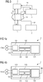
- Fig. 2 shows a monitoring system for a field device with Tamperschutz according to a second embodiment of the present invention.
- Fig. 2 a monitoring system according to Fig. 1
- the registration device 3 and the monitoring device 4 for the field device 1 are combined in a guide device 34.
- the field device 1 If the field device 1 has received a non-tampering assertion from the tamper monitoring device 2, the field device 1 transmits both field device data and the non-tampering assertion via the Internet 20 to the guide device 34.
- the guide device 34 first checks the non-tampering -Assertion that was transmitted from the field device 1. If this is valid, the transmitted field device data are accepted by the guide 34.
- Fig. 3 shows a monitoring system for a field device with Tamperschutz according to a third embodiment of the present invention.
- Fig. 3 essentially shows a monitoring system according to Fig. 1 , Unlike the surveillance system of Fig. 1 transmits the Tamperüberwachungs worn 2, as far as it has detected a physical manipulation of the field device 1, the non-tampering assertion not to the field device 1, but directly to the registration device 3, via the Internet 20, as in Fig. 3 shown. But it is also possible to use the non-tampering assertion via WLAN, according to Figures 1-5 via a mobile network, in particular GSM, UMTS, LTE, Wimax, CDMA or the like.
- a mobile network in particular GSM, UMTS, LTE, Wimax, CDMA or the like.
- the advantage thus achieved is that the field device does not have to be modified thereby, but the tamper monitoring device 2 can communicate with the registration device 3 independently of the field device 1, so that no interface for communication with the tamper monitoring device 2 has to be provided on the field device 1.
- Fig. 4a, 4b show tamper monitoring devices according to a first and a second embodiment.
- Reference numeral 2 denotes a tamper monitoring device, respectively.
- the respective tamper monitoring device 2 comprises a control computer 100, which is connected to a flash memory 101 and a RAM memory 102.
- the flash memory 101 serves as a configuration memory for the tamper monitoring device, while the RAM memory 102 serves as a working memory for the control computer 100.
- a power supply 103 is arranged, which is preferably designed such that, for example, the power supply 103 is battery-buffered or formed as a supercap, or this can provide energy by means of energy harvesting to use, for example, in power outages, the ambient temperature, vibration or air vibrations and so a continuous monitoring a field device 1 to allow.
- the respective Tamperüberwachungs worn 2 can be operated reliably.
- the respective tamper monitoring device 2 in each case comprises an input / output device 104, which are connected to sensors 104a for tamper monitoring.
- the sensors 104a are arranged in particular outside the housing of the respective tamper monitoring device 2.
- the respective tamper monitoring device 2 since it is designed for the specific task of tamper monitoring of the field device 1, can be optimized in terms of its energy consumption for this purpose.
- the control computer 100 can be in a so-called sleep mode, for example, for the majority of the time. If a tamper event is detected by the tamper monitoring device 2, the control computer 100 is reactivated.
- the tamper monitoring device 2 monitors by means of the sensors 104a, whether a tampering, that is, a physical manipulation of the field device 1 takes place.
- the sensors can be designed, for example, as motion sensors, light sensors, contacts, wire mesh or the like.
- the non-tampering assertion can be designed, for example, as a data structure which contains an identification number of the tamper monitoring device 2 and a time indication and / or a counter value.
- the data structure can be encrypted and provided with a cryptographic checksum, for example in the form of a digital signature or a message authentication code.
- the cryptographic checksum can be calculated by means of a cryptographic key stored on the tamper monitoring device 2 and provided by means of the interface 105.
- the interface 105 is in Fig. 4a wired, whereas in Fig. 4b is designed wirelessly.
- a non-tampering assertion can also contain at least one of the following information: identification information of the tamper monitoring device 2, additional information about the field device 1, which is monitored by the tamper monitoring device 2, a status of the field device 1, information about a physical manipulation, for example an indication of a housing opening a temperature at too high a temperature difference or the like, further a time information and / or a signature for authentication and integrity assurance.
- Fig. 5 shows a method for monitoring a tamper protection of a field device according to a first embodiment of the present invention.
- Reference numeral S1 denotes the step of checking whether manipulation has been performed on the field device 1
- reference numeral S2 indicates the step of issuing a non-manipulation certificate if a negative verification result has been detected
- reference numeral S3 indicates the step of transmitting the non-manipulation certificate
- reference numeral S4 the step of verifying the non-manipulation certificate by a registration device
- reference symbol S5 the step determining an active status of the field device by the registration device 3
- reference numeral S6 the step verifying the field device 1 by a monitoring device by transmitting the status of the field device 1 and reference symbol S7
- the step of transmitting field device data to the monitoring device 4 and reference symbol S8 the step of accepting the field device data by the monitoring device 4 as an active status, if an active Status of the field device 1 is present.
- the tamper monitoring device can be designed, for example, as a separate device, which is arranged in the field device to be monitored or a plurality of field devices to be monitored.
- the tamper monitoring device can be designed as a so-called intermediate unit, that is to say between the field device to be monitored and a fixed arrangement, for example a wall, a rail or the like.
- the tamper monitoring device can be embodied in a separate, additional housing, for example for a printed circuit board. It is also possible to install or integrate the tamper monitoring device and the sensors, which may be present for a tamper monitoring device, into the field device to be monitored itself.
- non-tampering certificate in the specification and in particular in the claims is to be understood as meaning not only a non-tampering acknowledgment message or a non-tampering assertion but also a message indicating that a physical manipulation of the monitored one Field device has taken place. If a physical manipulation is detected, a tampering certificate can be issued if a positive verification result has been determined. To be able to process this in the sense of the invention, in particular as shown in the claims and in the description of the figures, the field device, monitoring device and the registration device can be designed accordingly.
- the registration device can be further configured so that it is connected to a certification authority.
- the certification authority can provide the registration facility with a certificate revocation list or certificate revocation list in which a field device certificate of the field device monitored by the tamper monitoring device is listed.
- the field device certificate may be returned by an online certificate status protocol recipient or Online Certificate Status Protocol Responder. This allows an online transmission of the certificate cancellation list.
Description
Die Erfindung betrifft ein Verfahren zur Überwachung eines Tamperschutzes, ein Überwachungssystem für ein Feldgerät mit Tamperschutz und eine Verwendung eines Überwachungssystems.The invention relates to a method for monitoring a tamper protection, a monitoring system for a field device with tamper protection and a use of a monitoring system.
Feldgeräte, beispielsweise in Form von Verkehrszeichenanlagen zur Verkehrsregelung, Signalanlagen für Züge, Weichen, etc., sind üblicherweise mit einer Leitstelle oder einem Stellwerk zu deren Betätigung und Überwachung verbunden. Die Kommunikation zwischen Feldgerät und Leitstelle kann dabei sowohl drahtgebunden mittels entsprechend verlegter Kabel erfolgen oder auch drahtlos durch eine Funkverbindung.Field devices, for example in the form of traffic sign systems for traffic control, signaling systems for trains, switches, etc., are usually connected to a control center or a signal box for their operation and monitoring. The communication between field device and control center can be done either wired by means of appropriately routed cable or wirelessly through a radio link.
Um nun eine physikalische Manipulation an einem Feldgerät durch einen möglichen Angreifer erkennen zu können, können entsprechende Sensoren, beispielsweise Bewegungssensoren angeordnet werden. Um eine Manipulation von elektronischen Schaltungen in dem Feldgerät selbst zu erschweren, sind darüber hinaus Hardware-Security-integrierte Schaltungen bekannt geworden, welche kryptographische Schlüssel speichern und kryptographische Operationen durchführen können. Derartige integrierte Schaltungen verfügen üblicherweise über einen Tamperschutz, beispielsweise in Form von direkt auf der integrierten Schaltung angeordneten Sensoren. Diese sind dazu ausgebildet, ein unbefugtes Öffnen der integrierten Schaltung zu erkennen.In order to be able to detect a physical manipulation on a field device by a potential attacker, corresponding sensors, for example motion sensors, can be arranged. Moreover, in order to complicate manipulation of electronic circuits in the field device itself, hardware security integrated circuits have become known which can store cryptographic keys and perform cryptographic operations. Such integrated circuits usually have a tamper protection, for example in the form of sensors arranged directly on the integrated circuit. These are designed to detect unauthorized opening of the integrated circuit.
Eine solche Hardware-Security-integrierte Schaltung ist beispielsweise als "Trusted Platform Module" bekannt geworden, deren Daten unter http://de.wikipedia.org/wiki/trusted_platform_module abrufbar sind. Derartige integrierte Schaltungen werden beispielsweise in PCs oder Notebooks eingebaut.Such a hardware security integrated circuit has become known, for example, as a "Trusted Platform Module" whose data can be called up at http://de.wikipedia.org/wiki/trusted_platform_module. Such integrated circuits are installed, for example, in PCs or notebooks.
Schließlich ist es aus dem Bereich der Einbruchmeldeanlagen und Alarmanlagen für Gebäude bekannt geworden, Kontakte an Türen und Fenstern und/oder Bewegungsmelder einzusetzen, um einen Einbruch oder ein unbefugtes Öffnen oder Eindringen in das Gebäude oder einen Raum zu signalisieren. Im Falle eines Einbruchs in ein Gebäude wird beispielsweise ein Alarm durch eine Sirene oder Ähnliches ausgelöst und es ist auch möglich, gleichzeitig eine Polizeieinsatzzentrale zu kontaktieren. Die in Einbruchmeldeanlagen oder in Alarmanlagen verwendeten Sensoren selbst können zum Schutz der Alarmanlage gegen Manipulationen mit sogenannten Tamper-Sensoren ausgestattet sein, die eine Manipulation der Einbruchmeldeanlage oder der Alarmanlage erkennen, insbesondere, wenn deren Gehäuse geöffnet und/oder ein Sensor demontiert wird. Die Tamper-Sensoren übertragen dann die Information an die Alarmanlage, die wiederum einen Alarm auslöst.Finally, it has become known in the field of burglar alarm systems and alarm systems for buildings to use contacts on doors and windows and / or motion detectors to signal a burglary or unauthorized opening or intrusion into the building or a room. For example, in the event of a break-in to a building, an alarm is triggered by a siren or the like, and it is also possible to contact a police operations center at the same time. The sensors used in burglar alarm systems or in alarm systems themselves can be equipped to protect the alarm system against tampering with so-called tamper sensors, which detect a manipulation of burglar alarm or alarm, especially if the housing is opened and / or a sensor is dismantled. The tamper sensors then transmit the information to the alarm system, which in turn triggers an alarm.
Um Teile einer Leiterplatte oder eine ganze Leiterplatte vor einer Manipulation zu schützen, ist es weiter bekannt geworden, auf die Leiterplatte derart Metallplatten aufzuschrauben, so dass insgesamt ein Kondensator gebildet wird. Dessen Kapazität wird dann ständig überwacht, sodass bei einem Abweichen des üblichen Kapazitätswertes, zum Beispiel durch Berühren der Metallplatte oder deren Entfernen, eine Veränderung der Kapazität auftritt. Wird eine Veränderung der Kapazität festgestellt, kann ein Alarm ausgelöst werden und ein Speicher auf der Platine, der beispielsweise sensible Daten enthält, gelöscht werden, so dass ein Angreifer keinen Zugriff auf die sensiblen Daten erhält.In order to protect parts of a printed circuit board or an entire printed circuit board from being tampered with, it has also become known to screw metal plates onto the printed circuit board in such a way that a total of one capacitor is formed. Its capacity is then constantly monitored, so that a change in capacity occurs in a deviation of the usual capacitance value, for example by touching the metal plate or their removal. If a change in the capacity is detected, an alarm can be triggered and a memory on the board, which contains, for example, sensitive data, be deleted so that an attacker does not get access to the sensitive data.
Aus der
Diese Aufgabe wird durch ein Verfahren zur Überwachung eines Tamperschutzes eines Feldgeräts gelöst, umfassend die Schritte Überprüfen, ob eine Manipulation an dem Feldgerät erfolgt ist, Ausgeben eines Nicht-Manipulations-Zertifikats, falls ein negatives Überprüfungsergebnis ermittelt wurde, Übertragen des Nicht-Manipulations-Zertifikats, Überprüfen des Nicht-Manipulations-Zertifikats durch eine Registrierungseinrichtung, Festlegen eines aktiven Status des Feldgeräts durch die Registrierungseinrichtung, falls das Nicht-Manipulations-Zertifikat gültig ist, Überprüfen des Feldgeräts durch eine Überwachungseinrichtung mittels Abfragen des Status des Feldgeräts und Übertragen von Feldgerätdaten an die Überwachungseinrichtung, Akzeptieren der Feldgerätdaten durch die Überwachungseinrichtung, falls ein aktiver Status des Feldgeräts vorliegt.This object is achieved by a method for monitoring a tamper protection of a field device, comprising the steps of checking whether a tampering has been performed on the field device, issuing a non-tamper certificate, if a negative verification result has been determined, transmitting the tamper certificate Verifying the non-manipulation certificate by a registration device, setting the active state of the field device by the registration device, if the non-tampering certificate is valid, checking the field device by a monitoring device by querying the status of the field device and transmitting field device data to the Monitoring device, accepting the field device data by the monitoring device, if there is an active status of the field device.
Diese Aufgabe wird ebenfalls durch ein Überwachungssystem für ein Feldgerät mit Tamperschutz, insbesondere geeignet zur Durchführung eines Verfahrens gemäß zumindest einem der Ansprüche 1-5 gelöst, umfassend eine Tamperüberwachungseinrichtung, welche dazu ausgebildet ist, das Feldgerät zum Tamperschutz zu überwachen, eine Registrierungseinrichtung zur Registrierung und Statusüberwachung des Feldgeräts, eine Überwachungseinrichtung zum Steuern und Überwachen des Feldgeräts, wobei die Tamperüberwachungseinrichtung ausgebildet ist, zu überprüfen, ob eine Manipulation an dem Feldgerät erfolgt ist und ein Nicht-Manipulations-Zertifikat ausgibt, falls ein negatives Überprüfungsergebnis ermittelt wurde, und wobei die Registrierungseinrichtung ausgebildet ist, das Nicht-Manipulations-Zertifikat zu überprüfen, und einen aktiven Status des Feldgeräts bei gültigem Nicht-Manipulations-Zertifikat festzulegen, und wobei die Überwachungseinrichtung ausgebildet ist, einen Status des Feldgeräts zu überprüfen, und wobei die Überwachungseinrichtung ausgebildet ist, Feldgerätdaten zu akzeptieren, falls ein aktiver Status des Feldgeräts vorliegt.This object is likewise achieved by a monitoring system for a field device with tamper protection, in particular suitable for carrying out a method according to at least one of claims 1-5, comprising a tamper monitoring device, which is designed to monitor the field device for tamper protection, a registration device for registering and Status monitoring of the field device, a monitoring device for controlling and monitoring the field device, wherein the Tamperüberwachungseinrichtung is adapted to check whether a manipulation has been done on the field device and outputs a non-manipulation certificate, if a negative verification result has been determined, and wherein the registration device is configured to check the non-tampering certificate, and to set an active status of the field device with a valid non-tampering certificate, and wherein the monitoring device is configured to generate a St At the field device to check, and wherein the monitoring device is formed, field device data if there is an active status of the field device.
Diese Aufgabe wird ebenfalls durch die Verwendung eines Überwachungssystems gemäß zumindest einem der Ansprüche 6-10 zur Überwachung einer Verkehrsanlage oder zur Überwachung eines Umspannwerks gelöst.This object is also achieved by the use of a monitoring system according to at least one of claims 6-10 for monitoring a traffic system or for monitoring a substation.
Ein damit erzielter Vorteil ist, dass ein Tamperschutz auf einfache Weise und ohne größeren Aufwand insbesondere auch bei bereits vorhandenen Feldgeräten nachgerüstet werden kann. Ein weiterer Vorteil ist, dass die zu überwachenden Feldgeräte entwickelt und hergestellt werden können, ohne dass speziell ausgebildete Tamperschutzmaßnahmen im Feldgerät selbst berücksichtigt werden müssen. Durch das Verfahren zur Überwachung des Tamperschutzes wird auch lediglich das Feldgerät und/oder ein in dem Feldgerät hinterlegter Sicherheitsschlüssel gesperrt, sodass eventuell aus einem Speicher des Feldgeräts ausgelesene Daten, insbesondere der eventuelle ausgelesene Sicherheitsschlüssel, durch einen Angreifer diesem keinen Nutzen bringen. Ein weiterer Vorteil ist, dass eine derartige Überwachung eines Tamperschutzes für viele unterschiedliche Arten von Feldgeräten verwendet werden kann, was die Herstellungskosten für die jeweiligen Feldgeräte erheblich senkt. Der Tamperschutz muss lediglich einmalig entwickelt werden und nicht für jeden Feldgerätetyp gesondert. Darüber hinaus wird eine direkte Kommunikation zwischen der Tamperschutzüberwachungsvorrichtung und dem Feldgerät nicht benötigt. Auch dies spart Herstellungskosten.An advantage achieved with this is that a tamper protection can be retrofitted in a simple manner and without much effort especially in the case of existing field devices. A further advantage is that the field devices to be monitored can be developed and manufactured without specially trained tamper protection measures having to be taken into account in the field device itself. The method for monitoring the tamper protection also blocks only the field device and / or a security key stored in the field device so that any data read out from a memory of the field device, in particular the possibly read-out security key, can not be used by an attacker. Another advantage is that such tamper protection monitoring can be used for many different types of field devices, which significantly reduces manufacturing costs for the respective field devices. Tamper protection only has to be developed once and not separately for each field device type. In addition, a direct communication between the Tamperschutzüberwachungsvorrichtung and the field device is not needed. This also saves manufacturing costs.
Weitere vorteilhafte Weiterbildungen der Erfindung sind in den Unteransprüchen beschrieben.Further advantageous developments of the invention are described in the subclaims.
Zweckmäßigerweise erfolgt das Übertragen des Nicht-Manipulations-Zertifikats an die Registrierungseinrichtung mittels des Feldgeräts. Auf diese Weise werden keine zusätzlichen Schnittstellen zum Übertragen des Nicht-Manipulations-Zertifikats benötigt, sondern es können bereits bestehende Kommunikationskanäle oder -leitungen des Feldgeräts genutzt werden. Insgesamt wird also der Herstellungsaufwand für eine Tamperüberwachungseinrichtung für das Feldgerät gesenkt.Expediently, the transmission of the non-manipulation certificate to the registration device takes place by means of the field device. In this way, no additional interfaces for transmitting the non-manipulation certificate are needed, but it can already existing Communication channels or lines of the field device can be used. Overall, therefore, the production cost for a Tamperüberwachungseinrichtung for the field device is lowered.
Vorteilhafterweise erfolgt das Übertragen des Nicht-Manipulations-Zertifikats im Wesentlichen zeitgleich mit einem Übertragen der Feldgerätdaten, wobei insbesondere das Nicht-Manipulations-Zertifikat und die Feldgerätdaten an eine gemeinsame Leiteinrichtung, umfassend die Registrierungseinrichtung und die Überwachungseinrichtung übertragen werden. Der damit erzielte Vorteil ist, dass damit auf besonders schnelle und zuverlässige Weise überprüft werden kann, ob eine physikalische Manipulation des Feldgeräts stattgefunden hat.Advantageously, the transmission of the non-manipulation certificate takes place substantially simultaneously with a transmission of the field device data, wherein in particular the non-manipulation certificate and the field device data are transmitted to a common guidance device, comprising the registration device and the monitoring device. The advantage thus achieved is that it can be checked in a particularly rapid and reliable manner as to whether a physical manipulation of the field device has taken place.
Zweckmäßigerweise erfolgt das Übertragen des Nicht-Manipulations-Zertifikats mittels des Internet und/oder mittels zumindest eines Mobilfunknetzes und/oder mittels zumindest eines Satellitennetzes. Der damit erzielte Vorteil ist, dass damit auf einfache Weise, insbesondere wenn mehrere Übertragungsarten parallel verwendet werden, eine möglichst zuverlässige Übertragung gewährleistet ist. Gleichzeitig können übliche Übertragungswege genutzt werden, die kostengünstig sind, da die für die Übertragung benötigten Vorrichtungen in hoher Stückzahl verfügbar sind.Expediently, the transmission of the non-manipulation certificate takes place by means of the Internet and / or by means of at least one mobile radio network and / or by means of at least one satellite network. The advantage thus achieved is that in a simple manner, especially when multiple types of transmission are used in parallel, the most reliable transmission is guaranteed. At the same time conventional transmission paths can be used, which are inexpensive, since the devices required for the transmission are available in large quantities.
Zweckmäßigerweise werden zumindest die Schritte Überprüfen, ob eine Manipulation an dem Feldgerät erfolgt ist, Ausgeben eines Nicht-Manipulations-Zertifikats, falls ein negatives Überprüfungsergebnis ermittelt wurde und Übertragen des Nicht-Manipulations-Zertifikats in regelmäßigen zeitlichen Abständen durchgeführt. Der Vorteil dabei ist, dass damit zuverlässig bei einem Ausbleiben der Übermittlung des Nicht-Manipulations-Zertifikats der Status des entsprechenden Feldgeräts als inaktiv festgelegt wird.Conveniently, at least the steps of checking whether a manipulation has been carried out on the field device, issuing a non-manipulation certificate if a negative verification result has been determined and transmitting the non-manipulation certificate are carried out at regular time intervals. The advantage here is that reliable in the absence of the transmission of the non-manipulation certificate, the status of the corresponding field device is set as inactive.
Vorteilhafterweise ist bei dem Überwachungssystem eine Leiteinrichtung angeordnet, umfassend die Registrierungseinrichtung und die Überwachungseinrichtung. Der damit erzielte Vorteil ist, dass dadurch keine zusätzlichen externen Schnittstellen angeordnet, oder Kabel oder ähnliches verlegt werden müssen, um das Nicht-Manipulations-Zertifikat zu überprüfen. Gleichzeitig können Feldgerätdaten und Nicht-Manipulations-Zertifikat auf den bereits vorhandenen Kommunikationskanälen zwischen Feldgerät und Überwachungseinrichtung übertragen werden, was die Bedienung, Steuerung und Überwachung des Feldgeräts wesentlich vereinfacht.Advantageously, a guide device is arranged in the monitoring system, comprising the registration device and the monitoring device. The advantage thus achieved is that no additional external interfaces are arranged, or cables or the like must be laid in order to check the non-manipulation certificate. At the same time, field device data and non-manipulation certificate can be transmitted on the already existing communication channels between field device and monitoring device, which considerably simplifies the operation, control and monitoring of the field device.
Zweckmäßigerweise ist die Leiteinrichtung in Form eines SCADA-Leitstandes oder eines ERP-Systems ausgebildet. Der damit erzielte Vorteil ist, dass damit auf einfache und zuverlässige Weise eine Leiteinrichtung zur Verfügung gestellt wird. Darüber hinaus ist eine derartige Leiteinrichtung nicht nur zum Überwachen eines Tamperschutzes eines Feldgeräts ausgebildet, sondern kann auch noch zusätzliche Aufgaben wie beispielsweise eine Visualisierung, ein Regeln oder dergleichen von weiteren Systemen oder Vorrichtungen vornehmen.Conveniently, the guide is designed in the form of a SCADA control station or an ERP system. The advantage thus achieved is that a guide is provided in a simple and reliable manner. In addition, such a guide is not only designed to monitor a tamper protection of a field device, but can also perform additional tasks such as visualization, rules or the like of other systems or devices.
Zweckmäßigerweise umfasst zumindest eine der Einrichtungen eine Kommunikationsschnittstelle zum Internet, zu einem Mobilfunknetz und/oder zu einem Satellitennetz. Der damit erzielte Vorteil ist, dass damit, insbesondere wenn mehrere Übertragungsnetze parallel verwendet werden, eine möglichst zuverlässige Übertragung gewährleistet ist. Gleichzeitig können bereits vorhandene Übertragungswege genutzt werden, die kostengünstig sind, da die für die Übertragung benötigten Vorrichtungen gut verfügbar sind.Conveniently, at least one of the devices comprises a communication interface to the Internet, to a mobile radio network and / or to a satellite network. The advantage thus achieved is that it ensures reliable transmission, in particular if several transmission networks are used in parallel. At the same time existing transmission paths can be used, which are inexpensive, since the devices required for the transmission are well available.
Vorteilhafterweise weist die Tamperüberwachungseinrichtung eine autonome Energieversorgung auf. Auf diese Weise wird eine physikalische Manipulation der Tamperüberwachungseinrichtung selbst reduziert. Gleichzeitig wird die Ausfallsicherheit der Tamperüberwachungseinrichtung erhöht, da eine externe Energieversorgung nicht nötig ist und so bei einem Stromausfall die Tamperüberwachungseinrichtung trotzdem weiter das Feldgerät überwacht.Advantageously, the tamper monitoring device has an autonomous power supply. In this way a physical manipulation of the tamper monitoring device itself is reduced. At the same time, the reliability of the tamper monitoring device is increased, since an external power supply is not necessary and so the tamper monitoring device continues to monitor the field device in the event of a power failure.
Weitere Merkmale und Vorteile der Erfindung ergeben sich aus der nachfolgenden Beschreibung von Ausführungsbeispielen anhand der Zeichnung.Further features and advantages of the invention will become apparent from the following description of exemplary embodiments with reference to the drawing.
Dabei zeigt in schematischer Form
- Fig. 1
- ein Überwachungssystem für ein Feldgerät mit Tamperschutz gemäß einer ersten Ausführungsform der vorliegenden Erfindung;
- Fig. 2
- ein Überwachungssystem für ein Feldgerät mit Tamperschutz gemäß einer zweiten Ausführungsform der vorliegenden Erfindung;
- Fig. 3
- ein Überwachungssystem für ein Feldgerät mit Tamperschutz gemäß einer dritten Ausführungsform der vorliegenden Erfindung;
- Fig. 4a,4b
- Tamperüberwachungseinrichtungen gemäß einer ersten und zweiten Ausführungsform;
- Fig. 5
- ein Verfahren zur Überwachung eines Tamperschutzes eines Feldgeräts gemäß einer ersten Ausführungsform der vorliegenden Erfindung.
- Fig. 1
- a monitoring system for a field device with Tamperschutz according to a first embodiment of the present invention;
- Fig. 2
- a monitoring system for a field device with Tamperschutz according to a second embodiment of the present invention;
- Fig. 3
- a monitoring system for a field device with Tamperschutz according to a third embodiment of the present invention;
- Fig. 4a, 4b
- Tamper monitoring devices according to a first and second embodiment;
- Fig. 5
- a method for monitoring a tamper protection of a field device according to a first embodiment of the present invention.
In
Die Tamperüberwachungseinrichtung 2 stellt, soweit sie keine physikalische Manipulation oder einen Tamper-Event erkannt hat, ein Nicht-Manipulations-Zertifikat oder eine Non-Tampering-Assertion NTA aus und überträgt (Bezugszeichen 10) diese an das durch die Tamperüberwachungseinrichtung 2 geschützte Feldgerät 1. Die Non-Tampering-Assertion wird dann beispielsweise an eine Registrierungseinrichtung 3, die in Form eines Device-Registry-Servers ausgebildet ist, übertragen (Bezugszeichen 11). Dieser sperrt das Feldgerät 1, dessen Sicherheitsmerkmal oder dessen Security-Credentials, die beispielsweise in Form von Zertifikaten, Schlüsseln, Passwörtern oder Feldgerätkonten vorliegen, falls während einer bestimmten Zeitspanne keine der dem Feldgerät 1 zugeordneten Tamperüberwachungseinrichtung 2 ausgestellte Non-Tampering-Assertion bei dem Device-Registry-Server 3 vorliegt oder zu diesem übertragen wird. Der Status des Feldgeräts 1 ist dann als inaktiv festgelegt.The
Liegt eine gültige Non-Tampering-Assertion vor, wird der Status des Feldgeräts 1 als aktiv in der Registrierungseinrichtung 3 hinterlegt. Bereits währenddessen und/oder auch danach überträgt (Bezugszeichen 12) das Feldgerät 1 Feldgerätdaten, beispielsweise Steuerdaten oder Rückmeldungsdaten des Feldgeräts 1 an die Überwachungseinrichtung 4. Die Überwachungseinrichtung 4 kann beispielsweise als Steuerrechner, als speicherprogrammierbare Steuerung, als SCADA-Leitstand, als ERP-System oder dergleichen ausgebildet sein. Die Überwachungseinrichtung 4 prüft nun in einem weiteren Schritt (Bezugszeichen 13), ob der Status des Feldgeräts 1 aktiv ist. Hierzu fragt die Überwachungseinrichtung 4 den Status des Feldgeräts 1 bei der Registrierungseinrichtung 3 ab. Die Registrierungseinrichtung 3 überträgt (Bezugszeichen 14) den Status an die Überwachungseinrichtung 4. Ist der Status des Feldgeräts 1 gültig, akzeptiert die Überwachungseinrichtung 4 die vom Feldgerät 1 an die Überwachungseinrichtung 4 übermittelten Feldgerätdaten und kann Steuerdaten für das Feldgerät 1 übermitteln (Bezugszeichen 15).If there is a valid non-tampering assertion, the status of the field device 1 is stored as active in the
Falls eine physikalische Manipulation am Feldgerät 1 beispielsweise durch einen Angreifer vorgenommen werden sollte, wird dies durch die Tamperüberwachungseinrichtung 2 erkannt. Die Tamperüberwachungseinrichtung 2 stellt daraufhin keine weiteren Non-Tampering-Assertions aus und es werden somit auch keine Non-Tampering-Assertions mehr an das Feldgerät 1 übermittelt. Empfängt nun die Registrierungseinrichtung 3 keinerlei Non-Tampering-Assertions mehr vom Feldgerät 1, wird der Status des Feldgeräts 1 von der Registrierungseinrichtung 3 nach einer gewissen vorgebaren Zeitspanne als inaktiv hinterlegt. Selbst wenn es somit einem Angreifer gelingen sollte, Schlüssel zur Verschlüsselung aus dem Feldgerät 1 selbst durch eine physikalische Manipulation auszulesen, kann er diese nicht dazu benutzen, auf die Überwachungseinrichtung 4 zuzugreifen, da die Überwachungseinrichtung 4 vorab durch Abfrage bei der Registrierungseinrichtung 3 den Status des Feldgeräts 1 als inaktiv erkennt oder erkannt hat und somit keinerlei Feldgerätdaten mehr vom Feldgerät 1 akzeptiert und auch keine Steuerdaten mehr an das Feldgerät 1 übermitteltIf a physical manipulation on the field device 1 should be made, for example, by an attacker, this is detected by the
Im Wesentlichen zeigt
In den
Die Tamperüberwachungseinrichtung 2 überwacht mittels der Sensoren 104a, ob ein Tampering, das heißt, eine physikalische Manipulation des Feldgeräts 1 stattfindet. Die Sensoren können dabei beispielsweise als Bewegungssensoren, Lichtsensoren, Kontakte, Drahtgeflechte oder ähnliches ausgebildet sein. Solange keine physikalische Manipulation durch die Tamperüberwachungseinrichtung 2 festgestellt wird, stellt die Tamperüberwachungseinrichtung eine Non-Tampering-Assertion aus. Die Non-Tampering-Assertion kann dabei beispielsweise als Datenstruktur ausgebildet sein, die eine Identifikationsnummer der Tamperüberwachungseinrichtung 2 enthält und eine Zeitangabe und/oder einen Zählerwert. Die Datenstruktur kann dabei verschlüsselt und mit einer kryptographischen Prüfsumme, beispielsweise in Form einer digitalen Signatur oder eines Message Authentication Code, versehen werden. Die kryptographische Prüfsumme kann mittels eines auf der Tamperüberwachungseinrichtung 2 gespeicherten kryptographischen Schlüssels berechnet und mittels der Schnittstelle 105 bereitgestellt werden. Die Schnittstelle 105 ist in
Eine Non-Tampering-Assertion kann dabei auch zumindest eine der folgenden Informationen enthalten: eine Identifikationsinformation der Tamperüberwachungseinrichtung 2, zusätzlich Informationen zum Feldgerät 1, welches von der Tamperüberwachungseinrichtung 2 überwacht wird, einen Status des Feldgeräts 1, eine Information über eine physikalische Manipulation, beispielsweise einen Hinweis auf eine Gehäuseöffnung einer Temperatur bei einer zu hohen Temperaturdifferenz oder dergleichen, weiterhin eine Zeitinformation und/oder eine Signatur zur Authentifizierung und Integritätssicherung.A non-tampering assertion can also contain at least one of the following information: identification information of the
In
Obwohl die vorliegende Erfindung vorstehend anhand bevorzugter Ausführungsbeispiele beschrieben wurde ist sie nicht darauf beschränkt, sondern auf vielfältige Weise modifizierbar.Although the present invention has been described with reference to preferred embodiments, it is not limited thereto, but modifiable in many ways.
Die Tamperüberwachungseinrichtung kann beispielsweise als separates Gerät ausgeführt sein, welches bei dem zu überwachenden Feldgerät oder einer Mehrzahl von zu überwachenden Feldgeräten angeordnet ist. Die Tamperüberwachungseinrichtung kann dabei als sogenannte Zwischeneinheit ausgeführt sein, das heißt zwischen dem zu überwachenden Feldgerät und einer festen Anordnung, beispielsweise einer Wand, einer Schiene oder ähnliches festgelegt werden. Die Tamperüberwachungseinrichtung kann in einem separaten, zusätzlichen Gehäuse, beispielsweise für eine Leiterplatte ausgeführt sein. Es ist ebenso möglich, die Tamperüberwachungseinrichtung und die für eine Tamperüberwachungseinrichtung gegebenenfalls vorhandenen Sensoren in das zu überwachende Feldgerät selbst einzubauen oder zu integrieren.The tamper monitoring device can be designed, for example, as a separate device, which is arranged in the field device to be monitored or a plurality of field devices to be monitored. The tamper monitoring device can be designed as a so-called intermediate unit, that is to say between the field device to be monitored and a fixed arrangement, for example a wall, a rail or the like. The tamper monitoring device can be embodied in a separate, additional housing, for example for a printed circuit board. It is also possible to install or integrate the tamper monitoring device and the sensors, which may be present for a tamper monitoring device, into the field device to be monitored itself.
Unter Nicht-Manipulations-Zertifikat in der Beschreibung und insbesondere in den Ansprüchen ist nicht nur in Wesentlichen einen Non-Tampering-Bestätigungsnachricht oder eine Non-Tampering-Assertion zu verstehen, sondern ebenfalls auch eine Nachricht, die angibt, dass eine physikalische Manipulation des überwachten Feldgerätes stattgefunden hat. Wird eine physikalische Manipulation festgestellt, kann so ein Manipulationszertifikat ausgestellt werden, falls ein positives Überprüfungsergebnis ermittelt wurde. Um dieses im Sinne der Erfindung, insbesondere wie in den Ansprüchen und in den Figurenbeschreibungen dargestellt verarbeiten zu können, können das Feldgerät, Überwachungseinrichtung und die Registrierungseinrichtung entsprechend ausgebildet.The non-tampering certificate in the specification and in particular in the claims is to be understood as meaning not only a non-tampering acknowledgment message or a non-tampering assertion but also a message indicating that a physical manipulation of the monitored one Field device has taken place. If a physical manipulation is detected, a tampering certificate can be issued if a positive verification result has been determined. To be able to process this in the sense of the invention, in particular as shown in the claims and in the description of the figures, the field device, monitoring device and the registration device can be designed accordingly.
Die Registrierungseinrichtung kann weiter so ausgebildet sein, dass diese mit einer Zertifizierungsstelle verbunden ist. Die Zertifizierungsstelle kann dabei der Registrierungseinrichtung eine Zertifikatsaufhebungsliste oder Certificate Revocation List bereitstellen, in der ein Feldgerätzertifikat des von der Tamperüberwachungseinrichtung überwachten Feldgeräts aufgeführt ist. Alternativ kann das Feldgerätzertifikat durch von einem Online-Zertifikat-Status-Protokoll-Erwiderer oder Online-Certificate-Status-Protocol-Responder bereitgestellt werden. Dies ermöglicht eine Online-Übermittlung der Zertifikatsaufhebungsliste.The registration device can be further configured so that it is connected to a certification authority. The certification authority can provide the registration facility with a certificate revocation list or certificate revocation list in which a field device certificate of the field device monitored by the tamper monitoring device is listed. Alternatively, the field device certificate may be returned by an online certificate status protocol recipient or Online Certificate Status Protocol Responder. This allows an online transmission of the certificate cancellation list.
Claims (11)
- Method for monitoring a tamper protection of a field device (1),
comprising the steps:checking (S1) by a tamper monitoring device (2) whether a manipulation has taken place at the field device (1),outputting (S2) of a non-manipulation certificate by a tamper monitoring device (2) if a negative test result has been determined,transmitting (S3) of the non-manipulation certificate,checking (S4) of the non-manipulation certificate by a registration device (3),determining (S5) an active status of the field device (1) by the registration device (3) if the non-manipulation certificate is valid,checking (S6) of the field device (1) by a monitoring device (4) by inquiring about the status of the field device (1), andtransmitting (S7) of field device data to the monitoring device (4),accepting (S8) of the field device data by the monitoring device (4) if the field device (1) has an active status. - Method according to Claim 1,
characterized in that
the transmitting (S3) of the non-manipulation certificate to the registration device (3) takes place by means of the field device (1). - Method according to at least one of Claims 1-2,
characterized in that
the transmitting of the non-manipulation certificate occurs essentially at the same time as a transmitting of the field device data, wherein especially the non-manipulation certificate and the field device data are transmitted to a common control device comprising the registration device (3) and the monitoring device (4). - Method according to at least one of Claims 1-3,
characterized in that
the transmitting (S3) is carried out by means of the Internet (20) and/or by means of at least one mobile radio network and/or by means of at least one satellite network. - Method according to at least one of Claims 1-4,
characterized in that
at least the steps of checking (S1) whether a manipulation has occurred at the field device (1), outputting (S2) of a non-manipulation certificate if a negative test result has been determined and transmitting (S3) of the non-manipulation certificate are carried out at regular time intervals. - Monitoring system for a field device having tamper protection, especially suitable for carrying out a method according to at least one of Claims 1-5, comprising
a tamper monitoring device (2) which is designed for monitoring the field device (1) for tamper protection,
a registration device (3) for registering and monitoring the status of the field device (1),
a monitoring device (4) for controlling and monitoring the field device (1), wherein
the tamper monitoring device (2) is designed for checking whether a manipulation has occurred at the field device (1) and outputs a non-manipulation certificate if a negative test result has been determined, and wherein
the registration device (3) is designed for checking the non-manipulation certificate and determining an active status of the field device (1) in the case of a valid non-manipulation certificate, and wherein
the monitoring device (4) is designed for checking a status of the field device (1), and wherein
the monitoring device (4) is designed for accepting field device data if the field device (1) has an active status. - Monitoring system according to Claim 6,
characterized in that
a control device (34) is arranged comprising the registration device (3) and the monitoring device (4). - Monitoring system according to at least one of Claims 6-7,
characterized in that
the control device (34) is designed in the form of a SCADA control board or of an ERP system. - Monitoring system according to at least one of Claims 6-8,
characterized in that
at least one of the devices (2, 3, 4, 34) comprises a communication interface to the Internet, to a mobile radio network and/or to a satellite network. - Monitoring system according to at least one of Claims 6-9,
characterized in that
the tamper monitoring device (4) has an autonomous power supply. - Use of a monitoring system according to at least one of Claims 6-10 for monitoring a traffic installation or for monitoring a transformer substation.
Applications Claiming Priority (2)
| Application Number | Priority Date | Filing Date | Title |
|---|---|---|---|
| DE201110007572 DE102011007572A1 (en) | 2011-04-18 | 2011-04-18 | Method for monitoring tamper protection and monitoring system for a field device with tamper protection |
| PCT/EP2012/056517 WO2012143271A1 (en) | 2011-04-18 | 2012-04-11 | Method for monitoring a tamper protection and monitoring system for a field device having tamper protection |
Publications (2)
| Publication Number | Publication Date |
|---|---|
| EP2668607A1 EP2668607A1 (en) | 2013-12-04 |
| EP2668607B1 true EP2668607B1 (en) | 2018-04-04 |
Family
ID=46017820
Family Applications (1)
| Application Number | Title | Priority Date | Filing Date |
|---|---|---|---|
| EP12717242.7A Active EP2668607B1 (en) | 2011-04-18 | 2012-04-11 | Method for monitoring a tamper protection and monitoring system for a field device having tamper protection |
Country Status (5)
| Country | Link |
|---|---|
| US (1) | US9147088B2 (en) |
| EP (1) | EP2668607B1 (en) |
| DE (1) | DE102011007572A1 (en) |
| ES (1) | ES2674923T3 (en) |
| WO (1) | WO2012143271A1 (en) |
Families Citing this family (50)
| Publication number | Priority date | Publication date | Assignee | Title |
|---|---|---|---|---|
| US20140297206A1 (en) * | 2013-03-28 | 2014-10-02 | Kaspar Llc | Universal Smart Energy Transformer Module |
| AU2015296645A1 (en) | 2014-07-28 | 2017-02-16 | Econolite Group, Inc. | Self-configuring traffic signal controller |
| CN105282518A (en) * | 2015-11-12 | 2016-01-27 | 国家电网公司 | Accident transformer substation video frame automatic acquisition system |
| DE102016200850A1 (en) | 2016-01-21 | 2017-07-27 | Siemens Aktiengesellschaft | Method for operating a safety-relevant device and device |
| DE102016200907A1 (en) | 2016-01-22 | 2017-07-27 | Siemens Aktiengesellschaft | Method for operating a safety-relevant device and device |
| DE102016201176A1 (en) | 2016-01-27 | 2017-07-27 | Siemens Aktiengesellschaft | Method and apparatus for generating random bits |
| EP3274825B1 (en) | 2016-02-09 | 2018-11-07 | Siemens Aktiengesellschaft | Method and execution environment for the secure execution of program instructions |
| DE102016203534A1 (en) | 2016-03-03 | 2017-09-07 | Siemens Aktiengesellschaft | Method and analysis module for checking encrypted data transmissions |
| DE102016205289A1 (en) | 2016-03-31 | 2017-10-05 | Siemens Aktiengesellschaft | Method, processor and device for checking the integrity of user data |
| DE102016207294A1 (en) | 2016-04-28 | 2017-11-02 | Siemens Aktiengesellschaft | Procedure and certificate store for certificate management |
| DE102016207635A1 (en) | 2016-05-03 | 2017-11-09 | Siemens Aktiengesellschaft | Method and device for securing device access |
| DE102016207642A1 (en) | 2016-05-03 | 2017-11-09 | Siemens Aktiengesellschaft | Method and apparatus for authenticating a data stream |
| EP3252990A1 (en) | 2016-06-03 | 2017-12-06 | Siemens Aktiengesellschaft | Method and device for providing a secret for authenticating a system and/or components of the system |
| DE102016219926A1 (en) | 2016-10-13 | 2018-04-19 | Siemens Aktiengesellschaft | Method, sender and receiver for authentication and integrity protection of message content |
| DE102016221301A1 (en) | 2016-10-28 | 2018-05-03 | Siemens Aktiengesellschaft | Method and apparatus for providing a sender identification message for a sender |
| DE102017102677A1 (en) * | 2017-02-10 | 2018-08-16 | Endress+Hauser Conducta Gmbh+Co. Kg | Method for authenticating a field device of automation technology |
| EP3413530B1 (en) | 2017-06-09 | 2019-07-31 | Siemens Aktiengesellschaft | Method and device for exchanging messages |
| EP3435272B1 (en) | 2017-07-27 | 2020-11-04 | Siemens Aktiengesellschaft | Method and device for identifying an additive work piece |
| DE102017223099A1 (en) | 2017-12-18 | 2019-06-19 | Siemens Aktiengesellschaft | Apparatus and method for transferring data between a first and a second network |
| EP3503493A1 (en) | 2017-12-22 | 2019-06-26 | Siemens Aktiengesellschaft | Communication device and method for processing a network package |
| EP3502806A1 (en) | 2017-12-22 | 2019-06-26 | Siemens Aktiengesellschaft | Method for protecting the production data for producing a product |
| EP3506143B1 (en) | 2017-12-27 | 2024-02-14 | Siemens Aktiengesellschaft | Interface for a hardware security module |
| EP3509004A1 (en) | 2018-01-03 | 2019-07-10 | Siemens Aktiengesellschaft | Adaption of mac policies in industrial devices |
| EP3509247A1 (en) | 2018-01-03 | 2019-07-10 | Siemens Aktiengesellschaft | Method and key generator for creating an overall key with the support of a computer |
| EP3514743A1 (en) | 2018-01-22 | 2019-07-24 | Siemens Aktiengesellschaft | Device and method for providing instruction data for manufacturing an individualized product |
| EP3534282A1 (en) | 2018-03-01 | 2019-09-04 | Siemens Aktiengesellschaft | Method and security module for the computer-aided execution of program code |
| EP3557463B1 (en) | 2018-04-16 | 2020-10-21 | Siemens Aktiengesellschaft | Method and execution environment for executing program code on a control device |
| EP3562194B1 (en) | 2018-04-23 | 2021-07-28 | Siemens Aktiengesellschaft | Method for identifying at least one network slice configuration of a mobile network, communication system, and automation system |
| EP3562090B1 (en) | 2018-04-25 | 2020-07-01 | Siemens Aktiengesellschaft | Data processing device for processing a radio signal |
| EP3561713B1 (en) | 2018-04-25 | 2022-07-13 | Siemens Aktiengesellschaft | Retrieval device for authentication information, system and method for secure authentication |
| EP3561709B1 (en) | 2018-04-25 | 2020-07-29 | Siemens Aktiengesellschaft | Data processing apparatus, system, and method for proving or checking the security of a data processing apparatus |
| EP3562116A1 (en) | 2018-04-26 | 2019-10-30 | Siemens Aktiengesellschaft | Cryptographic key exchange or key agreement involving a device without network access |
| EP3570489B1 (en) | 2018-05-18 | 2020-04-08 | Siemens Aktiengesellschaft | Device and method for transforming blockchain data blocks |
| DK3584654T3 (en) | 2018-06-19 | 2020-08-10 | Siemens Ag | Hierarchically distributed ledger |
| EP3598364A1 (en) | 2018-07-17 | 2020-01-22 | Siemens Aktiengesellschaft | Timing constraint for transactions of a distributed database system |
| EP3598365A1 (en) | 2018-07-17 | 2020-01-22 | Siemens Aktiengesellschaft | Traffic shaping for transactions of a distributed database system |
| EP3598363A1 (en) | 2018-07-17 | 2020-01-22 | Siemens Aktiengesellschaft | Resource reservation for transactions of a distributed database system |
| EP3599740A1 (en) | 2018-07-25 | 2020-01-29 | Siemens Aktiengesellschaft | Control of a data network with respect to a use of a distributed database |
| EP3609148A1 (en) | 2018-08-06 | 2020-02-12 | Siemens Aktiengesellschaft | Methods and network node for processing measurements |
| EP3609240A1 (en) | 2018-08-09 | 2020-02-12 | Siemens Aktiengesellschaft | Computer-implemented method and network access server for connecting a network component with a network, in particular a mobile radio network, with an extended network access characteristic |
| EP3614319A1 (en) | 2018-08-20 | 2020-02-26 | Siemens Aktiengesellschaft | Tracking execution of an industrial workflow of a petri net |
| EP3629332A1 (en) | 2018-09-28 | 2020-04-01 | Siemens Aktiengesellschaft | Safe dispensing of a substance |
| EP3633914A1 (en) | 2018-10-05 | 2020-04-08 | Siemens Aktiengesellschaft | Method and system for traceable data processing using obfuscation |
| EP3637345A1 (en) | 2018-10-10 | 2020-04-15 | Siemens Aktiengesellschaft | Linking of identities in a distributed database |
| EP3687209A1 (en) | 2019-01-25 | 2020-07-29 | Siemens Aktiengesellschaft | Secure multi-hop communication paths |
| EP3693918A1 (en) | 2019-02-08 | 2020-08-12 | Siemens Gamesa Renewable Energy A/S | Operational data of an energy system |
| EP3736715A1 (en) | 2019-05-10 | 2020-11-11 | Siemens Aktiengesellschaft | Managing admission to a distributed database based on a consensus process |
| CN111027109A (en) * | 2019-11-15 | 2020-04-17 | 深圳中电长城信息安全系统有限公司 | Product safety monitoring method, device and system |
| US11899831B2 (en) | 2021-09-15 | 2024-02-13 | Hewlett Packard Enterprise Development Lp | Managing security of enclosure based on a task status and geographical location of the enclosure |
| DE102022127499B3 (en) | 2022-10-19 | 2024-01-25 | Cariad Se | Motor vehicle, control device and method for intrusion detection of a control device housing of a control device |
Family Cites Families (11)
| Publication number | Priority date | Publication date | Assignee | Title |
|---|---|---|---|---|
| US8549310B2 (en) * | 1996-04-08 | 2013-10-01 | Walker Digital, Llc | Method and apparatus for secure measurement certification |
| US6357007B1 (en) | 1998-07-01 | 2002-03-12 | International Business Machines Corporation | System for detecting tamper events and capturing the time of their occurrence |
| FR2826531B1 (en) * | 2001-06-26 | 2003-10-24 | France Telecom | CRYPTOGRAPHIC PROCESS FOR THE PROTECTION OF A CHIP AGAINST FRAUD |
| DE10238093B4 (en) * | 2002-08-21 | 2007-10-18 | Audi Ag | Vehicle controller |
| DE602004030426D1 (en) | 2003-03-06 | 2011-01-20 | Cypak Ab | PACKAGING WITH ORIGINALITY ASSURANCE |
| DE10339349A1 (en) | 2003-08-25 | 2005-03-24 | Endress + Hauser Process Solutions Ag | Input unit for process automating technology linked to a communications network has a detection unit for a user's electronic identification key with a signature entered by a user |
| DE102004017529A1 (en) | 2004-04-08 | 2005-11-03 | Siemens Ag | Automation network and automation device, network component and field device for such a network |
| DE102004043052B3 (en) * | 2004-09-06 | 2006-01-19 | Siemens Ag | Method for detecting tampering on an assembly with a sensor |
| US20070255966A1 (en) * | 2006-05-01 | 2007-11-01 | Vincenzo Condorelli | Cryptographic circuit with voltage-based tamper detection and response circuitry |
| US7945792B2 (en) * | 2007-10-17 | 2011-05-17 | Spansion Llc | Tamper reactive memory device to secure data from tamper attacks |
| US8188860B2 (en) * | 2007-10-22 | 2012-05-29 | Infineon Technologies Ag | Secure sensor/actuator systems |
-
2011
- 2011-04-18 DE DE201110007572 patent/DE102011007572A1/en not_active Withdrawn
-
2012
- 2012-04-11 US US14/112,534 patent/US9147088B2/en active Active
- 2012-04-11 WO PCT/EP2012/056517 patent/WO2012143271A1/en active Application Filing
- 2012-04-11 EP EP12717242.7A patent/EP2668607B1/en active Active
- 2012-04-11 ES ES12717242.7T patent/ES2674923T3/en active Active
Also Published As
| Publication number | Publication date |
|---|---|
| US20140047568A1 (en) | 2014-02-13 |
| US9147088B2 (en) | 2015-09-29 |
| EP2668607A1 (en) | 2013-12-04 |
| WO2012143271A1 (en) | 2012-10-26 |
| DE102011007572A1 (en) | 2012-10-18 |
| ES2674923T3 (en) | 2018-07-05 |
Similar Documents
| Publication | Publication Date | Title |
|---|---|---|
| EP2668607B1 (en) | Method for monitoring a tamper protection and monitoring system for a field device having tamper protection | |
| EP2628121B1 (en) | Device and method for protecting a security module from manipulation attempts in a field device | |
| EP2586178B1 (en) | Method for tamperproof key management | |
| WO2016096599A1 (en) | Method and apparatus for repercussion-free capture of data | |
| WO2020212051A1 (en) | Industrial automation device comprising a monitoring unit for checking and monitoring the integrity state of the industrial automation device | |
| WO2018157960A1 (en) | Method and system for activating a user access to a server coupled to an embedded system | |
| WO2019034338A1 (en) | Device and method for detecting unauthorized changes to an automation component | |
| EP2666117B1 (en) | Method for testing tamper protection of a field device and field device having tamper protection | |
| CN203271342U (en) | Internet of Things coded lock | |
| DE102010021256A1 (en) | Method for the dynamic authorization of a mobile communication device | |
| EP2376871B1 (en) | Method for operating a sensor apparatus and sensor apparatus | |
| DE102010028152B4 (en) | Recording history information in a field device | |
| EP2054782B1 (en) | Data recording apparatus | |
| EP2673733B1 (en) | Tamper protection device for protecting a field device against tampering | |
| EP3401831B1 (en) | Device and method for detecting a physical manipulation in an electronic security module | |
| DE102019212065A1 (en) | Method for logging a usage history of a battery system as well as battery system and motor vehicle | |
| DE102014207810A1 (en) | Method and device for operating a motor vehicle | |
| DE102021126959A1 (en) | Additional module for protection against tampering of a sensor | |
| EP3900258A1 (en) | Method for monitoring the integrity of a physical object | |
| JP6558942B2 (en) | Rack management system | |
| DE102021114559A1 (en) | Access-safe field device | |
| DE102020133063A1 (en) | Method for monitoring a field device and field device | |
| EP4147097A1 (en) | Tamper-proof expansion module | |
| EP4044551A1 (en) | Monitoring of a trustworthiness of a registration point | |
| EP3211493A1 (en) | Automation system for controlling a process, a device and/or an installation |
Legal Events
| Date | Code | Title | Description |
|---|---|---|---|
| PUAI | Public reference made under article 153(3) epc to a published international application that has entered the european phase |
Free format text: ORIGINAL CODE: 0009012 |
|
| 17P | Request for examination filed |
Effective date: 20130827 |
|
| AK | Designated contracting states |
Kind code of ref document: A1 Designated state(s): AL AT BE BG CH CY CZ DE DK EE ES FI FR GB GR HR HU IE IS IT LI LT LU LV MC MK MT NL NO PL PT RO RS SE SI SK SM TR |
|
| DAX | Request for extension of the european patent (deleted) | ||
| RAP1 | Party data changed (applicant data changed or rights of an application transferred) |
Owner name: SIEMENS AKTIENGESELLSCHAFT |
|
| REG | Reference to a national code |
Ref country code: DE Ref legal event code: R079 Ref document number: 502012012485 Country of ref document: DE Free format text: PREVIOUS MAIN CLASS: G06F0021060000 Ipc: G05B0019042000 |
|
| GRAP | Despatch of communication of intention to grant a patent |
Free format text: ORIGINAL CODE: EPIDOSNIGR1 |
|
| RIC1 | Information provided on ipc code assigned before grant |
Ipc: G06F 21/86 20130101ALI20171020BHEP Ipc: G05B 19/042 20060101AFI20171020BHEP |
|
| INTG | Intention to grant announced |
Effective date: 20171107 |
|
| GRAS | Grant fee paid |
Free format text: ORIGINAL CODE: EPIDOSNIGR3 |
|
| GRAA | (expected) grant |
Free format text: ORIGINAL CODE: 0009210 |
|
| AK | Designated contracting states |
Kind code of ref document: B1 Designated state(s): AL AT BE BG CH CY CZ DE DK EE ES FI FR GB GR HR HU IE IS IT LI LT LU LV MC MK MT NL NO PL PT RO RS SE SI SK SM TR |
|
| REG | Reference to a national code |
Ref country code: GB Ref legal event code: FG4D Free format text: NOT ENGLISH |
|
| REG | Reference to a national code |
Ref country code: FR Ref legal event code: PLFP Year of fee payment: 7 |
|
| REG | Reference to a national code |
Ref country code: CH Ref legal event code: EP |
|
| REG | Reference to a national code |
Ref country code: AT Ref legal event code: REF Ref document number: 986236 Country of ref document: AT Kind code of ref document: T Effective date: 20180415 |
|
| REG | Reference to a national code |
Ref country code: DE Ref legal event code: R096 Ref document number: 502012012485 Country of ref document: DE |
|
| REG | Reference to a national code |
Ref country code: IE Ref legal event code: FG4D Free format text: LANGUAGE OF EP DOCUMENT: GERMAN |
|
| REG | Reference to a national code |
Ref country code: CH Ref legal event code: NV Representative=s name: SIEMENS SCHWEIZ AG, CH |
|
| REG | Reference to a national code |
Ref country code: ES Ref legal event code: FG2A Ref document number: 2674923 Country of ref document: ES Kind code of ref document: T3 Effective date: 20180705 |
|
| REG | Reference to a national code |
Ref country code: NL Ref legal event code: MP Effective date: 20180404 |
|
| REG | Reference to a national code |
Ref country code: LT Ref legal event code: MG4D |
|
| PG25 | Lapsed in a contracting state [announced via postgrant information from national office to epo] |
Ref country code: NL Free format text: LAPSE BECAUSE OF FAILURE TO SUBMIT A TRANSLATION OF THE DESCRIPTION OR TO PAY THE FEE WITHIN THE PRESCRIBED TIME-LIMIT Effective date: 20180404 |
|
| PG25 | Lapsed in a contracting state [announced via postgrant information from national office to epo] |
Ref country code: SE Free format text: LAPSE BECAUSE OF FAILURE TO SUBMIT A TRANSLATION OF THE DESCRIPTION OR TO PAY THE FEE WITHIN THE PRESCRIBED TIME-LIMIT Effective date: 20180404 Ref country code: PL Free format text: LAPSE BECAUSE OF FAILURE TO SUBMIT A TRANSLATION OF THE DESCRIPTION OR TO PAY THE FEE WITHIN THE PRESCRIBED TIME-LIMIT Effective date: 20180404 Ref country code: LT Free format text: LAPSE BECAUSE OF FAILURE TO SUBMIT A TRANSLATION OF THE DESCRIPTION OR TO PAY THE FEE WITHIN THE PRESCRIBED TIME-LIMIT Effective date: 20180404 Ref country code: BG Free format text: LAPSE BECAUSE OF FAILURE TO SUBMIT A TRANSLATION OF THE DESCRIPTION OR TO PAY THE FEE WITHIN THE PRESCRIBED TIME-LIMIT Effective date: 20180704 Ref country code: AL Free format text: LAPSE BECAUSE OF FAILURE TO SUBMIT A TRANSLATION OF THE DESCRIPTION OR TO PAY THE FEE WITHIN THE PRESCRIBED TIME-LIMIT Effective date: 20180404 Ref country code: NO Free format text: LAPSE BECAUSE OF FAILURE TO SUBMIT A TRANSLATION OF THE DESCRIPTION OR TO PAY THE FEE WITHIN THE PRESCRIBED TIME-LIMIT Effective date: 20180704 Ref country code: FI Free format text: LAPSE BECAUSE OF FAILURE TO SUBMIT A TRANSLATION OF THE DESCRIPTION OR TO PAY THE FEE WITHIN THE PRESCRIBED TIME-LIMIT Effective date: 20180404 |
|
| PG25 | Lapsed in a contracting state [announced via postgrant information from national office to epo] |
Ref country code: GR Free format text: LAPSE BECAUSE OF FAILURE TO SUBMIT A TRANSLATION OF THE DESCRIPTION OR TO PAY THE FEE WITHIN THE PRESCRIBED TIME-LIMIT Effective date: 20180705 Ref country code: RS Free format text: LAPSE BECAUSE OF FAILURE TO SUBMIT A TRANSLATION OF THE DESCRIPTION OR TO PAY THE FEE WITHIN THE PRESCRIBED TIME-LIMIT Effective date: 20180404 Ref country code: LV Free format text: LAPSE BECAUSE OF FAILURE TO SUBMIT A TRANSLATION OF THE DESCRIPTION OR TO PAY THE FEE WITHIN THE PRESCRIBED TIME-LIMIT Effective date: 20180404 Ref country code: HR Free format text: LAPSE BECAUSE OF FAILURE TO SUBMIT A TRANSLATION OF THE DESCRIPTION OR TO PAY THE FEE WITHIN THE PRESCRIBED TIME-LIMIT Effective date: 20180404 |
|
| REG | Reference to a national code |
Ref country code: BE Ref legal event code: MM Effective date: 20180430 |
|
| PG25 | Lapsed in a contracting state [announced via postgrant information from national office to epo] |
Ref country code: PT Free format text: LAPSE BECAUSE OF FAILURE TO SUBMIT A TRANSLATION OF THE DESCRIPTION OR TO PAY THE FEE WITHIN THE PRESCRIBED TIME-LIMIT Effective date: 20180806 |
|
| REG | Reference to a national code |
Ref country code: DE Ref legal event code: R097 Ref document number: 502012012485 Country of ref document: DE |
|
| REG | Reference to a national code |
Ref country code: IE Ref legal event code: MM4A |
|
| PG25 | Lapsed in a contracting state [announced via postgrant information from national office to epo] |
Ref country code: SK Free format text: LAPSE BECAUSE OF FAILURE TO SUBMIT A TRANSLATION OF THE DESCRIPTION OR TO PAY THE FEE WITHIN THE PRESCRIBED TIME-LIMIT Effective date: 20180404 Ref country code: MC Free format text: LAPSE BECAUSE OF FAILURE TO SUBMIT A TRANSLATION OF THE DESCRIPTION OR TO PAY THE FEE WITHIN THE PRESCRIBED TIME-LIMIT Effective date: 20180404 Ref country code: LU Free format text: LAPSE BECAUSE OF NON-PAYMENT OF DUE FEES Effective date: 20180411 Ref country code: DK Free format text: LAPSE BECAUSE OF FAILURE TO SUBMIT A TRANSLATION OF THE DESCRIPTION OR TO PAY THE FEE WITHIN THE PRESCRIBED TIME-LIMIT Effective date: 20180404 Ref country code: CZ Free format text: LAPSE BECAUSE OF FAILURE TO SUBMIT A TRANSLATION OF THE DESCRIPTION OR TO PAY THE FEE WITHIN THE PRESCRIBED TIME-LIMIT Effective date: 20180404 Ref country code: RO Free format text: LAPSE BECAUSE OF FAILURE TO SUBMIT A TRANSLATION OF THE DESCRIPTION OR TO PAY THE FEE WITHIN THE PRESCRIBED TIME-LIMIT Effective date: 20180404 Ref country code: EE Free format text: LAPSE BECAUSE OF FAILURE TO SUBMIT A TRANSLATION OF THE DESCRIPTION OR TO PAY THE FEE WITHIN THE PRESCRIBED TIME-LIMIT Effective date: 20180404 |
|
| PLBE | No opposition filed within time limit |
Free format text: ORIGINAL CODE: 0009261 |
|
| STAA | Information on the status of an ep patent application or granted ep patent |
Free format text: STATUS: NO OPPOSITION FILED WITHIN TIME LIMIT |
|
| PG25 | Lapsed in a contracting state [announced via postgrant information from national office to epo] |
Ref country code: SM Free format text: LAPSE BECAUSE OF FAILURE TO SUBMIT A TRANSLATION OF THE DESCRIPTION OR TO PAY THE FEE WITHIN THE PRESCRIBED TIME-LIMIT Effective date: 20180404 Ref country code: BE Free format text: LAPSE BECAUSE OF NON-PAYMENT OF DUE FEES Effective date: 20180430 |
|
| 26N | No opposition filed |
Effective date: 20190107 |
|
| PG25 | Lapsed in a contracting state [announced via postgrant information from national office to epo] |
Ref country code: IE Free format text: LAPSE BECAUSE OF NON-PAYMENT OF DUE FEES Effective date: 20180411 |
|
| PG25 | Lapsed in a contracting state [announced via postgrant information from national office to epo] |
Ref country code: SI Free format text: LAPSE BECAUSE OF FAILURE TO SUBMIT A TRANSLATION OF THE DESCRIPTION OR TO PAY THE FEE WITHIN THE PRESCRIBED TIME-LIMIT Effective date: 20180404 |
|
| REG | Reference to a national code |
Ref country code: AT Ref legal event code: MM01 Ref document number: 986236 Country of ref document: AT Kind code of ref document: T Effective date: 20180411 |
|
| PG25 | Lapsed in a contracting state [announced via postgrant information from national office to epo] |
Ref country code: AT Free format text: LAPSE BECAUSE OF NON-PAYMENT OF DUE FEES Effective date: 20180411 |
|
| PGFP | Annual fee paid to national office [announced via postgrant information from national office to epo] |
Ref country code: ES Payment date: 20190725 Year of fee payment: 8 |
|
| PG25 | Lapsed in a contracting state [announced via postgrant information from national office to epo] |
Ref country code: MT Free format text: LAPSE BECAUSE OF FAILURE TO SUBMIT A TRANSLATION OF THE DESCRIPTION OR TO PAY THE FEE WITHIN THE PRESCRIBED TIME-LIMIT Effective date: 20180404 |
|
| PGFP | Annual fee paid to national office [announced via postgrant information from national office to epo] |
Ref country code: CH Payment date: 20190702 Year of fee payment: 8 |
|
| PG25 | Lapsed in a contracting state [announced via postgrant information from national office to epo] |
Ref country code: TR Free format text: LAPSE BECAUSE OF FAILURE TO SUBMIT A TRANSLATION OF THE DESCRIPTION OR TO PAY THE FEE WITHIN THE PRESCRIBED TIME-LIMIT Effective date: 20180404 |
|
| PG25 | Lapsed in a contracting state [announced via postgrant information from national office to epo] |
Ref country code: HU Free format text: LAPSE BECAUSE OF FAILURE TO SUBMIT A TRANSLATION OF THE DESCRIPTION OR TO PAY THE FEE WITHIN THE PRESCRIBED TIME-LIMIT; INVALID AB INITIO Effective date: 20120411 |
|
| PG25 | Lapsed in a contracting state [announced via postgrant information from national office to epo] |
Ref country code: CY Free format text: LAPSE BECAUSE OF FAILURE TO SUBMIT A TRANSLATION OF THE DESCRIPTION OR TO PAY THE FEE WITHIN THE PRESCRIBED TIME-LIMIT Effective date: 20180404 Ref country code: MK Free format text: LAPSE BECAUSE OF NON-PAYMENT OF DUE FEES Effective date: 20180404 |
|
| PG25 | Lapsed in a contracting state [announced via postgrant information from national office to epo] |
Ref country code: IS Free format text: LAPSE BECAUSE OF FAILURE TO SUBMIT A TRANSLATION OF THE DESCRIPTION OR TO PAY THE FEE WITHIN THE PRESCRIBED TIME-LIMIT Effective date: 20180804 |
|
| PGFP | Annual fee paid to national office [announced via postgrant information from national office to epo] |
Ref country code: GB Payment date: 20200402 Year of fee payment: 9 |
|
| REG | Reference to a national code |
Ref country code: CH Ref legal event code: PL |
|
| PG25 | Lapsed in a contracting state [announced via postgrant information from national office to epo] |
Ref country code: LI Free format text: LAPSE BECAUSE OF NON-PAYMENT OF DUE FEES Effective date: 20200430 Ref country code: CH Free format text: LAPSE BECAUSE OF NON-PAYMENT OF DUE FEES Effective date: 20200430 |
|
| REG | Reference to a national code |
Ref country code: ES Ref legal event code: FD2A Effective date: 20210831 |
|
| PG25 | Lapsed in a contracting state [announced via postgrant information from national office to epo] |
Ref country code: ES Free format text: LAPSE BECAUSE OF NON-PAYMENT OF DUE FEES Effective date: 20200412 |
|
| GBPC | Gb: european patent ceased through non-payment of renewal fee |
Effective date: 20210411 |
|
| PG25 | Lapsed in a contracting state [announced via postgrant information from national office to epo] |
Ref country code: GB Free format text: LAPSE BECAUSE OF NON-PAYMENT OF DUE FEES Effective date: 20210411 |
|
| PGFP | Annual fee paid to national office [announced via postgrant information from national office to epo] |
Ref country code: IT Payment date: 20230421 Year of fee payment: 12 Ref country code: DE Payment date: 20220620 Year of fee payment: 12 |
|
| PGFP | Annual fee paid to national office [announced via postgrant information from national office to epo] |
Ref country code: FR Payment date: 20230905 Year of fee payment: 13 |