EP2667522A2 - Elektronische Vorrichtungen, Verfahren und Computerprogrammprodukte zur Auswahl eines Antennenelements basierend auf einem drahtlosen Kommunikationsleistungskriterium - Google Patents
Elektronische Vorrichtungen, Verfahren und Computerprogrammprodukte zur Auswahl eines Antennenelements basierend auf einem drahtlosen Kommunikationsleistungskriterium Download PDFInfo
- Publication number
- EP2667522A2 EP2667522A2 EP13164047.6A EP13164047A EP2667522A2 EP 2667522 A2 EP2667522 A2 EP 2667522A2 EP 13164047 A EP13164047 A EP 13164047A EP 2667522 A2 EP2667522 A2 EP 2667522A2
- Authority
- EP
- European Patent Office
- Prior art keywords
- antenna
- antenna elements
- signal reception
- wireless communication
- wireless signal
- Prior art date
- Legal status (The legal status is an assumption and is not a legal conclusion. Google has not performed a legal analysis and makes no representation as to the accuracy of the status listed.)
- Withdrawn
Links
- 238000004891 communication Methods 0.000 title claims abstract 24
- 238000000034 method Methods 0.000 title claims abstract 11
- 238000004590 computer program Methods 0.000 title 1
- 238000011156 evaluation Methods 0.000 claims abstract 10
- 230000005540 biological transmission Effects 0.000 claims abstract 5
- 230000000116 mitigating effect Effects 0.000 claims 1
Images











Classifications
-
- H—ELECTRICITY
- H04—ELECTRIC COMMUNICATION TECHNIQUE
- H04B—TRANSMISSION
- H04B7/00—Radio transmission systems, i.e. using radiation field
- H04B7/02—Diversity systems; Multi-antenna system, i.e. transmission or reception using multiple antennas
- H04B7/04—Diversity systems; Multi-antenna system, i.e. transmission or reception using multiple antennas using two or more spaced independent antennas
- H04B7/08—Diversity systems; Multi-antenna system, i.e. transmission or reception using multiple antennas using two or more spaced independent antennas at the receiving station
- H04B7/0802—Diversity systems; Multi-antenna system, i.e. transmission or reception using multiple antennas using two or more spaced independent antennas at the receiving station using antenna selection
- H04B7/0817—Diversity systems; Multi-antenna system, i.e. transmission or reception using multiple antennas using two or more spaced independent antennas at the receiving station using antenna selection with multiple receivers and antenna path selection
- H04B7/082—Diversity systems; Multi-antenna system, i.e. transmission or reception using multiple antennas using two or more spaced independent antennas at the receiving station using antenna selection with multiple receivers and antenna path selection selecting best antenna path
-
- H—ELECTRICITY
- H04—ELECTRIC COMMUNICATION TECHNIQUE
- H04B—TRANSMISSION
- H04B7/00—Radio transmission systems, i.e. using radiation field
- H04B7/02—Diversity systems; Multi-antenna system, i.e. transmission or reception using multiple antennas
- H04B7/04—Diversity systems; Multi-antenna system, i.e. transmission or reception using multiple antennas using two or more spaced independent antennas
- H04B7/06—Diversity systems; Multi-antenna system, i.e. transmission or reception using multiple antennas using two or more spaced independent antennas at the transmitting station
- H04B7/0602—Diversity systems; Multi-antenna system, i.e. transmission or reception using multiple antennas using two or more spaced independent antennas at the transmitting station using antenna switching
- H04B7/0608—Antenna selection according to transmission parameters
Definitions
- Wireless communication devices such as WIFI 802.11N and LTE compliant communication devices, are increasingly using Multiple Input-Multiple Output (MIMO) antenna technology to provide increased data communication rates with decreased error rates.
- MIMO antenna includes at least two antenna elements.
- MIMO technology may offer significant increases in data throughput and/or transmission range without the need for additional bandwidth or transmit power. It can achieve this due to the ability of MIMO to obtain higher spectral efficiency (more bits per second per hertz of bandwidth) and/or reduced fading.
- MIMO based systems allow the use of a variety of coding techniques that take advantage of the presence of multiple transmit and receive antennas.
- wireless communications performed over a MIMO channel can use beamforming, spatial multiplexing and/or diversity coding techniques.
- the operational performance of a MIMO antenna depends upon obtaining sufficient decoupling and decorrelation between its antenna elements. It is therefore usually desirable to position the antenna elements far apart within a device and/or to use radiofrequency (RF) shielding therebetween while balancing its size and other design constraints.
- RF radiofrequency
- antennas for MIMO systems may utilize spatial separation, or physical separation, to reduce correlation between antennas.
- Mobile terminals may need to cover multiple-bands in Long Term Evolution (LTE) environments.
- Antenna systems may, therefore, be required to cover up to seven different frequency bands, for example.
- the antenna systems may be required to meet the requirements of Single Input-Single Output (SISO) and Single Input-Multiple Output (SIMO) for 3GPP and 2G bands.
- SISO Single Input-Single Output
- SIMO Single Input-Multiple Output
- the antenna configuration will generally be required to fulfill Specific Absorption Rate (SAR) requirements and other industry standards as well.
- SAR Specific Absorption Rate
- User effects such as the way a user holds a mobile terminal relative to the positioning of the antenna elements therein may affect the over the air performance of the device.
- a method of operating an electronic device includes providing a plurality of antenna elements, evaluating a wireless communication performance criterion to obtain a performance evaluation, and assigning a first one of the plurality of antenna elements to a main wireless signal reception and transmission path and a second one of the plurality of antenna elements to a diversity wireless signal reception path based on the performance evaluation.
- evaluating the wireless communication performance criterion comprises determining transmission power for signals transmitted through each of the plurality of antenna elements and power associated with signals reflected back through each of the plurality of antenna elements.
- evaluating the wireless communication performance criterion comprises determining Received Signal Strength Indication (RSSI) data for each of the plurality of antenna elements.
- RSSI Received Signal Strength Indication
- evaluating the wireless communication performance criterion comprises processing feedback from a wireless basestation, the feedback including signal strength information for signals transmitted from each of the plurality of antenna elements.
- evaluating the wireless communication performance criterion comprises determining proximity information of structure abutting the mobile terminal via at least one sensor.
- the method further comprises determining whether first and second communication channels associated with the main wireless signal reception path and the diversity wireless signal reception path, respectively, have changed and updating channel estimation models and/or multipath mitigation modules in a digital baseband signal processing section of the electronic device responsive to a determination that the first and second communication channels associated with the main wireless signal reception path and the diversity wireless signal reception path, respectively, have changed.
- the method further comprises determining whether first and second communication channels associated with the main wireless signal reception path and the diversity wireless signal reception path, respectively, have changed, routing signals received on the first communication channel through the diversity wireless signal reception path in a radio frequency processing section of the electronic device and through the main wireless signal reception path in a digital baseband signal processing section of the electronic device responsive to a determination that the first and second communication channels associated with the main wireless signal reception path and the diversity wireless signal reception path, respectively, have changed, and routing signals received on the second communication channel through the main wireless signal reception path of the radio frequency processing section of the electronic device and through the diversity wireless signal reception path in the digital baseband signal processing section of the electronic device responsive to the determination that the first and second communication channels associated with the main wireless signal reception path and the diversity wireless signal reception path, respectively, have changed.
- the electronic device is a mobile terminal.
- a computer program product comprises a non-transitory computer readable program medium, the computer readable program medium comprises computer readable program code configured to carry out methods as described above.
- a method of operating an electronic device comprises providing a plurality of antenna elements, evaluating a wireless communication performance criterion to obtain a performance evaluation, and selecting a pair of the plurality of antenna elements for use in wireless communication based on the performance evaluation.
- evaluating the wireless communication performance criterion comprises determining a Multiplexing Efficiency where the Multiplexing Efficiency is given by Multiplexing Efficiency - 1 - ⁇ e ⁇ ⁇ 1 ⁇ ⁇ 2
- ⁇ 1 and ⁇ 2 are a total efficiency of a first and a second one of the plurality of antenna elements, respectively and ⁇ e is an envelope correlation coefficient between the first and second one of the plurality of antenna elements.
- the electronic device is a mobile terminal.
- a computer program product comprises a non-transitory computer readable program medium, the computer readable program medium comprises computer readable program code configured to carry out methods as described above.
- an electronic device comprises a plurality of antenna elements and antenna selection control circuitry that is configured to evaluate a wireless communication performance criterion to obtain a performance evaluation and assign a first one of the plurality of antenna elements to a main wireless signal reception and transmission path and a second one of the plurality of antenna elements to a diversity wireless signal reception path based on the performance evaluation.
- the antenna selection control circuitry is configured to evaluate the wireless communication performance criterion by determining transmission power for signals transmitted through each of the plurality of antenna elements and power associated with signals reflected back through each of the plurality of antenna elements.
- the antenna selection control circuitry is configured to evaluate the wireless communication performance criterion by determining Received Signal Strength Indication (RSSI) data for each of the plurality of antenna elements.
- RSSI Received Signal Strength Indication
- the antenna selection control circuitry is configured to evaluate the wireless communication performance criterion by processing feedback from a wireless basestation, the feedback including signal strength information for signals transmitted from each of the plurality of antenna elements.
- the antenna selection control circuitry is configured to evaluate the wireless communication performance criterion by determining proximity information of structure abutting the mobile terminal via at least one sensor.
- the electronic device is a mobile terminal.
- an electronic device comprises a plurality of antenna elements and antenna selection control circuitry that is configured to evaluate a wireless communication performance criterion to obtain a performance evaluation and select a pair of the plurality of antenna elements for use in wireless communication based on the performance evaluation.
- the electronic device is a mobile terminal.
- the present invention may be embodied as methods, electronic devices, and/or computer program products. Accordingly, the present invention may be embodied in hardware and/or in software (including firmware, resident software, micro-code, etc.). Furthermore, the present invention may take the form of a computer program product comprising a computer-usable or computer-readable storage medium having computer-usable or computer-readable program code embodied in the medium for use by or in connection with an instruction execution system.
- a computer-usable or computer-readable medium may be any medium that can contain, store, communicate, propagate, or transport the program for use by or in connection with the instruction execution system, apparatus, or device.
- the computer-usable or computer-readable medium may be, for example but not limited to, an electronic, magnetic, optical, electromagnetic, infrared, or semiconductor system, apparatus, device, or propagation medium. More specific examples (a nonexhaustive list) of the computer-readable medium would include the following: an electrical connection having one or more wires, a portable computer diskette, a random access memory (RAM), a read-only memory (ROM), an erasable programmable read-only memory (EPROM or Flash memory), an optical fiber, and a compact disc read-only memory (CD-ROM).
- RAM random access memory
- ROM read-only memory
- EPROM or Flash memory erasable programmable read-only memory
- CD-ROM compact disc read-only memory
- the computer-usable or computer-readable medium could even be paper or another suitable medium upon which the program is printed, as the program can be electronically captured, via, for instance, optical scanning of the paper or other medium, then compiled, interpreted, or otherwise processed in a suitable manner, if necessary, and then stored in a computer memory.
- the term “signal” may take the form of a continuous waveform and/or discrete value(s), such as digital value(s) in a memory or register.
- the terms “module,” “circuit,” and “controller” may take the form of digital circuitry, such as computer-readable program code executed by an instruction processing device(s) (e.g., general purpose microprocessor and/or digital signal processor), and/or analog circuitry.
- embodiments of the invention may be implemented in an electronic device, such as a mobile terminal, that includes a Multiple-Input Multiple-Output (MIMO) antenna that is configured to transmit and receive RF signals in two or more frequency bands.
- MIMO antenna may be configured, for example, to transmit/receive RF communication signals in the frequency ranges used for cellular communications (e.g., cellular voice and/or data communications), WLAN communications, and/or TransferJet communications, etc.
- the term "mobile terminal” may include a satellite or cellular radiotelephone with or without a multi-line display; a Personal Communications System (PCS) terminal that may combine a cellular radiotelephone with data processing, facsimile and data communications capabilities; a PDA that can include a radiotelephone, pager, Internet/intranet access, Web browser, organizer, calendar and/or a global positioning system (GPS) receiver; and a conventional laptop and/or palmtop receiver or other appliance that includes a radiotelephone transceiver.
- Mobile terminals may also be referred to as "pervasive computing" devices.
- the network may provide services broadly labeled as PCS (Personal Communications Services) including advanced digital cellular systems conforming to standards such as IS-136 and IS-95, lower-power systems such as DECT (Digital Enhanced Cordless Telephone), data communications services such as CDPD (Cellular Digital Packet Data), and other systems such as CDMA-2000, that are proposed using a format commonly referred to as Wideband Code Division Multiple Access (WCDMA).
- PCS Personal Communications Services
- advanced digital cellular systems conforming to standards such as IS-136 and IS-95
- DECT Digital Enhanced Cordless Telephone
- CDPD Cellular Digital Packet Data
- CDMA-2000 Wideband Code Division Multiple Access
- LTE mobile devices may need antenna systems that cover seven frequency bands (760-800 MHz, 824-894 MHz, 880-960 MHz, 1710-1850 MHz, 1820- 1990 MHz, 1920-2170 MHz, and 2500-2700 MHz.
- the antenna systems used in LTE devices may also need to meet the requirements of Single In-Single Output (SISO) and Single In-Multiple Output (SIMO) applications for other 3GPP and 2G bands.
- SISOO Single In-Single Output
- SIMO Single In-Multiple Output
- the antenna systems may be required to meet Specific Absorption Rate (SAR) requirements and other industry standards.
- SAR Specific Absorption Rate
- an intelligent control system may be used to select particular antenna(s) for transmitting and receiving wireless signals based on various performance factors and criteria.
- the antenna selection may be based on various modes of operation of the device, such as particular ways a user holds the device during operation.
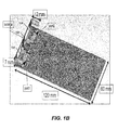
- FIGS. 1A and 1B illustrate a mobile terminal 100 including a MIMO antenna that includes at least two radiating elements or antennas 152, 154.
- the first and second radiating elements 152, 154 may be formed on a planar substrate, such as on a conventional printed circuit board, which includes a dielectric material, ceramic material, or insulation material.
- the first and second radiating elements 152, 154 are adjacent to grounding elements 160, which couple the first and second radiating elements 152, 154 to a ground plane on the printed circuit board.
- the first and second radiating elements 152, 154 may be formed by patterning a conductive (e.g., metallization) layer on a printed circuit board.
- the ground plane 160 may act as a counterpoise for each of the first and second radiating elements 152, 154.
- RF signals are coupled to the first radiating element 152 through a first feed element or port 162, while RF signals are coupled to the second radiating element 154 through a second feed element or port 164.
- the first feed element 162 is coupled to the first radiating element 152 near an end of the first radiating element 152, so that the first radiating element 152 generally extends away from the first feed element 162 along an upper end of the mobile terminal 100.
- the second feed element 164 is coupled to the second radiating element 154 near an end of the second radiating element 154, so that the second radiating element 152 generally extends away from the second feed element 164 along the upper end of the mobile terminal 100.
- the two radiating elements 152 and 154 are separated via an isolator element 166.
- the radiating elements or antennas 152, 154 may be disposed in a variety of positions in mobile terminal 100 in accordance with various embodiments of the present invention. Moreover, more than two antennas can be used in other embodiments of the present invention.
- the efficiency of a single antenna is increased when the antenna excites the fundamental mode of the antenna's counterpoise.
- both antennas in a MIMO antenna excite the same mode, they will tend to experience mutual coupling. This coupling causes the signals on the antennas to become correlated, which can reduce the performance of the MIMO antenna system.
- the MIMO antennas are used in a dual band system, i.e., a system that is intended to operate over more than one frequency range.
- the antenna may transmit/receive signals in both a 750MHz band and an 850MHz band.
- the correlation of radiating elements that use the same ground plane may be unacceptably high, such as about 0.8 to 0.9.
- FIG. 2 is a block diagram that illustrates control circuitry for selecting an antenna in a mobile terminal that includes a MIMO antenna system 200 according to some embodiments of the present invention.
- the MIMO antenna system 200 comprises antennas 152 and 154 that are connected to downconvertor circuitry via a multiplexer 205.
- the downconvertor circuitry comprises low noise amplifiers (LNAs) 210 and 215 in the main path and diversity path, respectively, along with power amplifiers (PAs) 220 in the main path.
- LNAs low noise amplifiers
- PAs power amplifiers
- An RF ASIC 225 is coupled to the amplifier circuits 210, 215, and 220 and may be configured to implement the mixer circuits, oscillators, and input/output filters to generate the complex baseband signal from a received RF signal via antennas 152 and 154 and to generate the RF signal for transmission on one of the antennas 152 and 154 from a complex baseband signal.
- the multiplexer 205 is operable in response to various control circuitry and signals to select one the antennas 152 and 154 for transmission and to select which of the antennas 152 and 154 is to be used for the main path signal and which is to be used for the diversity path signal when processing a received RF signal.
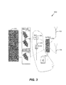
- FIG. 3 is a block diagram that illustrates control circuitry for selecting an antenna in a mobile terminal that includes a MIMO antenna system 300 according to some embodiments of the present invention.
- the MIMO antenna system 300 is similar to that illustrated in FIG. 2 , but includes a coupler 305 connected in the main path.
- a detector 310 and microcontroller 315 connect the coupler to the multiplexer 205.
- the coupler 305 can be a single directional coupler or a bi-directional coupler.
- the detector 310 can be implemented in a variety of different ways in accordance with various embodiments of the present invention. For example, the detector 310 may detect amplitude only or may be a complex detector capable of detecting both amplitude and phase.
- the detector 310 can measure power associated with transmitted signals sent through the power amplifiers 220 via each antenna 152 and 154 along with the power associated with signals reflected back through the two antennas 152 and 154. Based on these measurements, the microcontroller 315 can select which of the two antennas 152 and 154 to use for transmission. Once an antenna is selected for transmission, the microcontroller 315 may at certain times, such as on a periodic schedule and/or if performance degrades below some threshold level, switch which antenna is used for transmission to collect additional signal transmission power and signal reflection power data to determine if the current antenna is still the preferred choice. In the embodiments of FIG. 3 , however, the effects of absorption loss may not be considered, which may be dominant for some antenna types and/or conditions.
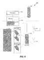
- FIG. 4 is a block diagram that illustrates control circuitry for selecting an antenna in a mobile terminal that includes a MIMO antenna system 400 according to some embodiments of the present invention.
- the MIMO antenna system 400 is similar to that illustrated in FIG. 2 , but includes a processor 405 coupled to a memory 410 that includes a Received Signal Strength Indication (RSSI) antenna selection module 415.
- the RF ASIC 225 provides RSSI data, which is processed using the antenna selection module 415.
- the RSSI data may be collected for both antennas 152 and 154 (i.e., both the main and diversity paths) and the RSSI antenna selection module 415 may determine which antenna provides signals with the higher RSSI power values.
- the multiplexer 205 may then be used to assign the antenna with the best RSSI power value to the main path in response to a signal from the processor 405.
- the selection of which antenna to assign to the main path and which to assign to the diversity path is based solely on the performance in the frequency bands involved in signal reception. This may not be a disadvantage, however, in systems where the correlation between the receive and transmit frequency performance is high.
- FIG. 5 is a block diagram that illustrates control circuitry for selecting an antenna in a mobile terminal that includes a MIMO antenna system 500 according to some embodiments of the present invention.
- the MIMO antenna system 500 is similar to that illustrated in FIG. 2 , but includes a processor 505 coupled to a memory 510 that includes a base station feedback antenna selection module 515.
- the radio frequency signal processing platform 525 provides feedback information from the base station 520 with regard to signal strength received from the device, which is processed using the base station feedback antenna selection module 515.
- the radio frequency processing platform 525 may include such functionality as the main and diversity path amplifiers 220, 210, and 215 along with the RF ASIC 225 described above.
- the base station signal strength feedback data may be collected for both antennas 152 and 154 and the base station feedback antenna selection module 515 may determine which antenna transmits signals with the higher power values.
- the multiplexer 205 may then be used to assign the antenna with the best transmit power values based on the base station feedback to the main path in response to a signal from the processor 505.
- the base station feedback antenna selection module 515 may at certain times, such as on a periodic schedule or if performance degrades below some threshold level, switch which antenna is used for transmission to collect feedback from the base station 520 with respect to the transmitted signal strength.
- FIG. 6 is a block diagram that illustrates control circuitry for selecting an antenna in a mobile terminal that includes a MIMO antenna system 600 according to some embodiments of the present invention.
- the MIMO antenna system 600 is similar to that illustrated in FIG. 2 , but includes a processor 605 coupled to a memory 610 that includes a proximity sensor antenna selection module 615.
- one or more proximity sensors 620 may detect placement of a user's hand on the device or some other external object that may affect operation of the antennas 152 and 154.
- the proximity information captured by the proximity sensors 620 is processed using the proximity sensor antenna selection module 515.
- the proximity sensor antenna selection module 615 may determine which antenna is preferred for transmission and/or receiving based on the likelihood of reduced interference by the proximity of the antenna to outside structure.
- the multiplexer 205 may then be used to assign the antenna with that has the least interference from external structure based on the proximity sensor 620 data to the main path in response to a signal from the processor 605.
- orientation circuitry may be used in place of or in addition to the proximity sensors 620 to determine the particular orientation of the device.
- Such orientation information may also be processed using the proximity sensor antenna selection module 615 to determine which antenna is preferred for transmission and/or receiving based on the likelihood of reduced interference as compared to the other antenna based on the orientation of the device.
- FIG. 7 is a block diagram of digital baseband processing circuitry 700 for a mobile terminal that includes a MIMO antenna system according to some embodiments of the present invention.
- an intelligent control system may be used to select particular antenna(s) for transmitting and receiving wireless signals based on various performance factors and criteria. Such dynamic selection, however, may impact decoding of the received wireless signals in the digital baseband.
- a typical signal received by mobile terminal will have been affected by multipath fading.
- the receiver circuitry uses channel estimation algorithms to model the channel state information or channel properties of the communication link.
- the modeling may include an estimation of the transfer function and noise associated with the communication link.
- the RF ASIC outputs the complex baseband signals for the main path and the diversity path.
- the digital baseband processing circuitry 700 includes channel estimation modules 705 and 710 for the main and diversity signal paths, respectively.
- the channel estimation modules 705, 710 are configured to filter the received main and diversity signals based on a statistical modeling of the main and diversity signal paths.
- Multipath mitigation modules 715 and 720 are used to compensate for the effects of multipath fading, for example.
- the multipath mitigation modules 715 and 720 may implement any multipath mitigation algorithm used and the signals from the main signal path and diversity signal path are coherently combined at the adder 725.
- the output of the adder 725 is provided to a decoding module 730 to extract the symbol information from the baseband signal.
- an antenna switch control module 735 is used to update the channel estimation modules 705 and 710 so as to reconfigure the filters to model the appropriate communication link.
- the antenna switch control module 735 updates the multipath mitigation modules 715 and 720 to model the appropriate communication link.
- the channel estimation models uses in the channel estimation modules 705 and 710 are swapped and the multipath mitigation models used in the multipath mitigation modules 715 and 720 are swapped.
- FIG. 8 is a block diagram that illustrates control circuitry for selecting an antenna in a mobile terminal that includes a MIMO antenna system 800 according to some embodiments of the present invention.
- the MIMO antenna system 800 is similar to that illustrated in FIG. 2 , but includes a second multiplexer 805 that is responsive to an antenna control signal for selecting which antennas 152, 154 to use for the main and diversity signal paths.
- a second multiplexer 805 that is responsive to an antenna control signal for selecting which antennas 152, 154 to use for the main and diversity signal paths.
- the channel estimation modules 705, 710 and/or multipath mitigation modules 715, 720 have been configured for the respective main and diversity communication links when the antennas 152, 154 are swapped in response to an antenna selection signal as described above with respect to the FIGS.
- the multiplexer 805 switches the signals received from the antennas 152 and 154 back to their former paths so that there is no need to change the settings in the digital baseband processing circuitry, i.e.., the channel estimation modules 705, 710 and/or multipath mitigation modules 715, 720.
- a combiner or duplexer 810 is shown to handle the two way communication between the multiplexer 205 and the amplifiers 220 and 210. The embodiments of FIGS. 7 and 8 may allow antenna reassignments between the main and diversity paths to be conducted at any time without any loss in channel estimation and signal demodulation performance.
- FIGS. 2 - 8 have been described with respect to comparing the performance of two antennas and determining which to assign to a main demodulation path and which to assign to a diversity demodulation path.
- Some mobile terminals may include a quad-element LTE MIMO antenna array. In some applications only the optimal two antenna elements of the four are selected for operation with the other two antenna elements being disabled. As the antenna elements are typically spread out in the mobile terminal, the two antenna elements providing the best performance may vary depending on, for example, user effects or other external obstructions affecting signal reception.
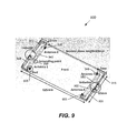
- FIG. 9 illustrates a mobile terminal 900 including a quad element MIMO antenna array comprising radiating elements or antennas 1 - 4 905, 910, 915, and 920 configured as shown.
- Antenna element 1 905 includes port 925 and grounding port 930;
- antenna element 2 910 includes port 935 and grounding port 940;
- antenna element 3 905 includes port 945 and grounding port 950;
- antenna element 4 920 includes port 955 and grounding port 960.
- antenna ij represents antenna i and antenna j operating with the other two antenna elements being operationally disabled via leaving their ports and grounding ports open.
- the performance of a particular antenna pairing in a quad element MIMO antenna array may be represented by a parameter called multiplexing efficiency.
- FIGS. 10A - 10D The s parameters, total efficiency, envelope correlation coefficients, and multiplexing efficiency, of the different dual-element combinations in the adaptive quad-element LTE MIMO antenna array 900 of FIG. 9 are shown in FIGS. 10A - 10D , respectively. It can be observed that each combination can cover the bands of 750-960 MHz and 1700-2700 MHz with a high efficiency and multiplexing efficiency.
- FIGS. 11A - 11C show the comparisons between the simulated and measured s parameters, envelope correlation coefficient, multiplexing efficiency, of antenna 12 and antenna 34 in the quad-element array.
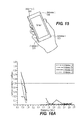
- FIG. 12 illustrates the mobile terminal 900 held in a user's hand with the speaker pressed up against the user's ear. In this orientation the mobile terminal 900 may be considered to be in talk mode.
- FIG. 13A illustrates the envelope correlation coefficient for the various antenna pairings with the mobile terminal 900 in the orientation of FIG. 12 .
- the correlation of antenna 34 in low frequency has been reduced much more efficiently than the other combinations.
- the antenna 34 case it has two characteristics: large human body coverage of the whole dual-element antenna array and human a hand placed approximately symmetrically between two ports. When the dual-element array satisfies these two characteristics the user hand can be viewed as a scatter causing structure. This scatter may efficiently separate the radiation patterns of the two MIMO antenna elements to achieve a low correlation.
- the multiplexing efficiency of the different dual-element combinations for the talk mode orientation of FIG. 12 can be calculated and is shown in FIG. 13B .
- low band antenna 34 can be used while in high band antenna 12 may be used.
- MEL multiplexing efficiency loss
- FIG. 15 illustrates the mobile terminal 900 held in a user's hand. When the mobile terminal 900 is in this orientation it may be considered to be in data mode.
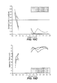
- FIG. 16A illustrates the envelope correlation coefficient when the mobile terminal 900 is in the data mode orientation of FIG. 15 .
- the correlation of antenna 13 also has the lowest correlation and its characteristics are the same as those for the talk mode orientation of FIG. 12 .
- Multiplexing efficiency for the data mode orientation of FIG. 15 is illustrated in FIG. 16B . It can be observed that antenna 34 (which has the most coverage) is a little better than antenna 12 in the low band due to the lower correlation, but not so significant because of the high loss of port 955. Therefore, for the data mode, antenna 12 or antenna 34 can be used in the low band and antenna 12 can be used in the high band based on the simulations.
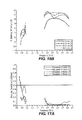
- FIGS. 17A and 17B The simulated and measured envelope correlation coefficient along with the multiplexing efficiency of antenna 12 and antenna 34 when the mobile terminal 900 is in the data mode orientation are shown in FIGS. 17A and 17B , respectively.
- antenna 12 provides similar performance to the simulated results in the low band, but antenna 34 provides worse performance than the simulated results due to the greater losses of port 955. Antenna 12 may, therefore, be preferred to antenna 34 for low band applications.
- the measured losses are higher than the simulations for the high band antenna pairings, but the relative losses between antenna 12 and antenna 34 are approximately the same as the simulations. Therefore, when the mobile terminal 900 is in the data mode orientation, antenna 12 can be used in low band and in high band applications based on the measurement results.
- FIG. 18 illustrates the mobile terminal 900 held in a user's two hands. This orientation of the mobile terminal 900 may be called the reading mode.
- FIG. 19A illustrates the envelope correlation coefficient when the mobile terminal 900 is in the reading mode orientation of FIG. 18 .
- antenna 14 has the greatest amount of coverage due to the user's hands and, therefore, has the lowest envelope correlation.
- Multiplexing efficiency for the reading mode orientation of FIG. 18 is illustrated in FIG. 19B . Due to the similar efficiency in the low band, the envelope correlation is the dominant factor for the high multiplexing efficiency. As a result, antenna 14 has the best multiplexing efficiency as shown in FIG. 19B . In the higher bands multiplexing efficiency may be important because of the similar envelope correlations. Therefore, when the mobile terminal 900 is in reading mode, antenna 14 may be used for low band applications and antenna 23 may be used for high band applications.
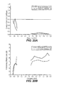
- FIGS. 20A and 20B The simulated and measured envelope correlation coefficient along with the multiplexing efficiency of antenna 12 when the mobile terminal 900 is in the reading mode orientation are shown in FIGS. 20A and 20B , respectively. As can be seen in FIGS. 20A and 20B , the measured results generally agree with the simulations.
- antenna 34, antenna 12, and antenna 14 can be used when the mobile terminal 900 is in talk mode, data mode, and reading mode, respectively.
- antenna 13, antenna 12, and antenna 23 can be used when the mobile terminal 900 is in talk mode, data mode, and reading mode, respectively.
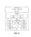
- FIG. 21 is a block diagram of a wireless communication terminal 2100 that includes a MIMO antenna array in accordance with some embodiments of the present invention.
- the mobile terminal 2100 includes a MIMO antenna array 2110, a transceiver 2140, a processor 2127, and can further include a conventional display 2108, keypad 2102, speaker 2104, mass memory 2128, microphone 2106, and/or camera 2124, one or more of which may be electrically grounded to the same ground plane as the MIMO antenna array 2110.
- the MIMO antenna array 2110 may be structurally configured as shown for the MIMO antenna arrays of FIGS. 1B and 9 , or may be configured in accordance with various other embodiments of the present invention.
- MIMO antennas in accordance with various embodiments of the present invention may be embodied as, but are not limited to, ground free monopole antennas, planar inverted F- antennas (PIFA) radiating elements and/or on-ground antenna radiating elements as well.
- PIFA planar inverted F- antennas
- the transceiver 2140 may include transmit/receive circuitry (TX/RX) that provides separate communication paths for supplying/receiving RF signals to different radiating elements of the MIMO antenna 2110 via their respective RF feeds. Accordingly, when the MIMO antenna 2110 includes two radiating antenna elements 2152, 2154, the transceiver 2140 may include two transmit/receive circuits 2142, 2144 connected to different ones of the antenna elements via the respective RF feeds.
- TX/RX transmit/receive circuitry
- the transceiver 2140 in cooperation with the processor 2127 may be configured to communicate according using at least one radio access technology in two or more frequency ranges.
- the at least one radio access technology may include, but is not limited to, WLAN (e.g., 802.11), WiMAX (Worldwide Interoperability for Microwave Access), TransferJet, 3GPP LTE (3rd Generation Partnership Project Long Term Evolution), Universal Mobile Telecommunications System (UMTS), Global Standard for Mobile (GSM) communication, General Packet Radio Service (GPRS), enhanced data rates for GSM evolution (EDGE), DCS, PDC, PCS, code division multiple access (CDMA), wideband-CDMA, and/or CDMA2000.
- WLAN e.g., 802.11
- WiMAX Worldwide Interoperability for Microwave Access
- TransferJet 3GPP LTE (3rd Generation Partnership Project Long Term Evolution
- UMTS Universal Mobile Telecommunications System
- GSM Global Standard for Mobile
- GPRS General Packet Radio Service
- EDGE enhanced data rates
Landscapes
- Engineering & Computer Science (AREA)
- Computer Networks & Wireless Communication (AREA)
- Signal Processing (AREA)
- Mobile Radio Communication Systems (AREA)
- Radio Transmission System (AREA)
Applications Claiming Priority (1)
| Application Number | Priority Date | Filing Date | Title |
|---|---|---|---|
| US13/480,048 US8804560B2 (en) | 2012-05-24 | 2012-05-24 | Electronic devices, methods, and computer program products for selecting an antenna element based on a wireless communication performance criterion |
Publications (2)
| Publication Number | Publication Date |
|---|---|
| EP2667522A2 true EP2667522A2 (de) | 2013-11-27 |
| EP2667522A3 EP2667522A3 (de) | 2014-02-19 |
Family
ID=48141782
Family Applications (1)
| Application Number | Title | Priority Date | Filing Date |
|---|---|---|---|
| EP13164047.6A Withdrawn EP2667522A3 (de) | 2012-05-24 | 2013-04-17 | Elektronische Vorrichtungen, Verfahren und Computerprogrammprodukte zur Auswahl eines Antennenelements basierend auf einem drahtlosen Kommunikationsleistungskriterium |
Country Status (2)
| Country | Link |
|---|---|
| US (1) | US8804560B2 (de) |
| EP (1) | EP2667522A3 (de) |
Cited By (2)
| Publication number | Priority date | Publication date | Assignee | Title |
|---|---|---|---|---|
| CN110784839A (zh) * | 2019-10-30 | 2020-02-11 | 陕西天基通信科技有限责任公司 | 一种电梯多媒体终端4g/5g专用信号的覆盖终端及方法 |
| CN114189266A (zh) * | 2020-09-14 | 2022-03-15 | 中兴通讯股份有限公司 | 一种终端通信控制方法、通信设备及存储介质 |
Families Citing this family (27)
| Publication number | Priority date | Publication date | Assignee | Title |
|---|---|---|---|---|
| JP6193052B2 (ja) * | 2013-08-19 | 2017-09-06 | 株式会社ソニー・インタラクティブエンタテインメント | 入力装置および電子機器 |
| US10326513B2 (en) * | 2013-09-26 | 2019-06-18 | Avago Technologies International Sales Pte. Limited | Methods of antenna system control in massive MIMO systems |
| US9791490B2 (en) | 2014-06-09 | 2017-10-17 | Apple Inc. | Electronic device having coupler for tapping antenna signals |
| US10128924B2 (en) * | 2014-06-23 | 2018-11-13 | Dell Products, Lp | Proximity activated antenna switch system and method therefor |
| US9594147B2 (en) | 2014-10-03 | 2017-03-14 | Apple Inc. | Wireless electronic device with calibrated reflectometer |
| US9893752B2 (en) * | 2014-10-31 | 2018-02-13 | Skyworks Solutions, Inc. | Diversity receiver front end system with variable-gain amplifiers |
| KR101740024B1 (ko) * | 2014-11-25 | 2017-05-26 | 주식회사 케이엠더블유 | 기지국 시스템에서의 안테나 제어 시스템 및 그 구성 방법 |
| US9496932B1 (en) * | 2015-05-20 | 2016-11-15 | Dell Products Lp | Systems and methods of dynamic MIMO antenna configuration and/or reconfiguration for portable information handling systems |
| WO2017074488A1 (en) * | 2015-10-27 | 2017-05-04 | Intel IP Corporation | Devices and methods for robust measurement and data receiving |
| KR102476051B1 (ko) * | 2016-04-22 | 2022-12-09 | 삼성전자주식회사 | 전자 장치 및 전자 장치의 안테나 전환 방법 |
| CN106099365A (zh) * | 2016-08-16 | 2016-11-09 | 西北工业大学 | 低耦合度超宽频带mimo天线 |
| CN109904596B (zh) * | 2017-12-07 | 2023-06-02 | 中兴通讯股份有限公司 | 天线、终端及实现天线调控的方法和天线调控装置 |
| CN111801848A (zh) * | 2018-01-05 | 2020-10-20 | 维斯普瑞公司 | 角天线阵列设备、系统和方法 |
| CN108494460B (zh) * | 2018-03-13 | 2021-09-28 | Oppo广东移动通信有限公司 | 电子设备及天线切换方法 |
| US10904181B2 (en) | 2018-09-28 | 2021-01-26 | Snap Inc. | Generating customized graphics having reactions to electronic message content |
| US11700038B2 (en) | 2019-05-30 | 2023-07-11 | Cypress Semiconductor Corporation | Enhancement of range and throughput for multi-antenna wireless communications devices |
| CN112448745B (zh) * | 2019-08-30 | 2023-12-26 | 北京小米移动软件有限公司 | Wifi天线选择控制装置、方法及终端 |
| US12506262B2 (en) * | 2020-01-03 | 2025-12-23 | Dell Products L.P. | Proximity sensing using an antenna front end module |
| US11710899B2 (en) | 2020-06-29 | 2023-07-25 | Dell Products L.P. | Proximity sensing using an antenna front end module |
| US11469799B2 (en) | 2020-01-03 | 2022-10-11 | Dell Products L.P. | Unified antenna system and method supporting 4G and 5G modems in same device |
| CN111277294B (zh) * | 2020-01-21 | 2021-08-31 | Oppo广东移动通信有限公司 | 天线选择方法及相关产品 |
| CN111277293B (zh) | 2020-01-21 | 2021-08-06 | Oppo广东移动通信有限公司 | 客户前置设备、天线控制方法和计算机可读存储介质 |
| US11211964B1 (en) | 2020-06-29 | 2021-12-28 | Dell Products L.P. | Multi-rat dynamic transmit power boost using an antenna front end module |
| US11349544B2 (en) | 2020-06-30 | 2022-05-31 | Dell Products L.P. | System and method for dynamic dual transmit diversity switching for a multi-radio-access-technology device |
| US11335994B2 (en) | 2020-06-30 | 2022-05-17 | Dell Products L.P. | System and method for dynamic multi-transmit antenna and proximity sensor reconfiguration for a multi-radio-access-technology multi-mode device |
| CN113092880B (zh) * | 2021-03-04 | 2022-04-05 | 北京航空航天大学 | 一种基于相位旋转的多通道阵列接收机幅相不一致性检测方法 |
| CN113825090A (zh) * | 2021-09-30 | 2021-12-21 | 广州广日电梯工业有限公司 | 电梯的无线通信系统以及电梯的无线通信方法 |
Family Cites Families (4)
| Publication number | Priority date | Publication date | Assignee | Title |
|---|---|---|---|---|
| JP2004363863A (ja) | 2003-06-04 | 2004-12-24 | Sony Ericsson Mobilecommunications Japan Inc | 携帯無線端末 |
| JP2010206357A (ja) | 2009-03-02 | 2010-09-16 | Fujitsu Ltd | 無線送受信装置 |
| US20110249576A1 (en) * | 2009-12-21 | 2011-10-13 | Qualcomm Incorporated | Antenna selection based on performance metrics in a wireless device |
| EP2567467A2 (de) * | 2010-05-04 | 2013-03-13 | Celeno Communications Ltd. | System und verfahren für kanalstatusbedingte rückkopplung in mimo-systemen |
-
2012
- 2012-05-24 US US13/480,048 patent/US8804560B2/en not_active Expired - Fee Related
-
2013
- 2013-04-17 EP EP13164047.6A patent/EP2667522A3/de not_active Withdrawn
Non-Patent Citations (1)
| Title |
|---|
| None |
Cited By (2)
| Publication number | Priority date | Publication date | Assignee | Title |
|---|---|---|---|---|
| CN110784839A (zh) * | 2019-10-30 | 2020-02-11 | 陕西天基通信科技有限责任公司 | 一种电梯多媒体终端4g/5g专用信号的覆盖终端及方法 |
| CN114189266A (zh) * | 2020-09-14 | 2022-03-15 | 中兴通讯股份有限公司 | 一种终端通信控制方法、通信设备及存储介质 |
Also Published As
| Publication number | Publication date |
|---|---|
| EP2667522A3 (de) | 2014-02-19 |
| US8804560B2 (en) | 2014-08-12 |
| US20130315076A1 (en) | 2013-11-28 |
Similar Documents
| Publication | Publication Date | Title |
|---|---|---|
| US8804560B2 (en) | Electronic devices, methods, and computer program products for selecting an antenna element based on a wireless communication performance criterion | |
| US11509441B2 (en) | State prediction process and methodology | |
| US9020447B2 (en) | Electronic devices, methods, and computer program products for making a change to an antenna element based on a power level of a transmission power amplifier | |
| US9397388B2 (en) | Dual feed antenna | |
| US9231669B2 (en) | Modal cognitive diversity for mobile communication MIMO systems | |
| EP2793400B1 (de) | Dualaustauschschalter zur Erfüllung der Linearitätsanforderungen einer Trägeraggregation | |
| KR101537644B1 (ko) | 무선 디바이스에서의 동적 안테나 선택 | |
| KR101054713B1 (ko) | 다중대역 다중모드 콤팩트 안테나 시스템 | |
| US20080111748A1 (en) | Antenna system having plural selectable antenna feed points and method of operation thereof | |
| WO2007094970A1 (en) | Antenna system having receiver antenna diversity and configurable transmission antenna and method of management thereof | |
| KR20090016494A (ko) | 다중 대역 안테나 장치 | |
| WO2011084716A1 (en) | Antenna selection based on measurements in a wireless device | |
| EP2107636A1 (de) | Antennenanordnung mit Empfangsdiversität und tragbare Vorrichtung damit | |
| JP2006254082A (ja) | 移動体通信端末 | |
| JP4922956B2 (ja) | 無給電素子を備えたマルチアンテナ装置 | |
| Okano | Performance of multi-band multi-antenna for mobile terminal employing folded inverted-L antennas |
Legal Events
| Date | Code | Title | Description |
|---|---|---|---|
| PUAI | Public reference made under article 153(3) epc to a published international application that has entered the european phase |
Free format text: ORIGINAL CODE: 0009012 |
|
| AK | Designated contracting states |
Kind code of ref document: A2 Designated state(s): AL AT BE BG CH CY CZ DE DK EE ES FI FR GB GR HR HU IE IS IT LI LT LU LV MC MK MT NL NO PL PT RO RS SE SI SK SM TR |
|
| AX | Request for extension of the european patent |
Extension state: BA ME |
|
| PUAL | Search report despatched |
Free format text: ORIGINAL CODE: 0009013 |
|
| AK | Designated contracting states |
Kind code of ref document: A3 Designated state(s): AL AT BE BG CH CY CZ DE DK EE ES FI FR GB GR HR HU IE IS IT LI LT LU LV MC MK MT NL NO PL PT RO RS SE SI SK SM TR |
|
| AX | Request for extension of the european patent |
Extension state: BA ME |
|
| RIC1 | Information provided on ipc code assigned before grant |
Ipc: G01R 27/06 20060101ALI20140113BHEP Ipc: H04B 7/08 20060101AFI20140113BHEP |
|
| 17P | Request for examination filed |
Effective date: 20140819 |
|
| RBV | Designated contracting states (corrected) |
Designated state(s): AL AT BE BG CH CY CZ DE DK EE ES FI FR GB GR HR HU IE IS IT LI LT LU LV MC MK MT NL NO PL PT RO RS SE SI SK SM TR |
|
| STAA | Information on the status of an ep patent application or granted ep patent |
Free format text: STATUS: EXAMINATION IS IN PROGRESS |
|
| 17Q | First examination report despatched |
Effective date: 20190125 |
|
| GRAP | Despatch of communication of intention to grant a patent |
Free format text: ORIGINAL CODE: EPIDOSNIGR1 |
|
| STAA | Information on the status of an ep patent application or granted ep patent |
Free format text: STATUS: GRANT OF PATENT IS INTENDED |
|
| RIC1 | Information provided on ipc code assigned before grant |
Ipc: H04B 7/06 20060101AFI20200428BHEP Ipc: H04B 7/08 20060101ALI20200428BHEP |
|
| INTG | Intention to grant announced |
Effective date: 20200519 |
|
| STAA | Information on the status of an ep patent application or granted ep patent |
Free format text: STATUS: THE APPLICATION IS DEEMED TO BE WITHDRAWN |
|
| 18D | Application deemed to be withdrawn |
Effective date: 20200930 |