EP2667219A1 - Detection of radar objects with a radar sensor of a motor vehicle - Google Patents
Detection of radar objects with a radar sensor of a motor vehicle Download PDFInfo
- Publication number
- EP2667219A1 EP2667219A1 EP13161284.8A EP13161284A EP2667219A1 EP 2667219 A1 EP2667219 A1 EP 2667219A1 EP 13161284 A EP13161284 A EP 13161284A EP 2667219 A1 EP2667219 A1 EP 2667219A1
- Authority
- EP
- European Patent Office
- Prior art keywords
- radar
- distribution
- model
- expected
- distance
- Prior art date
- Legal status (The legal status is an assumption and is not a legal conclusion. Google has not performed a legal analysis and makes no representation as to the accuracy of the status listed.)
- Granted
Links
Images


Classifications
-
- G—PHYSICS
- G01—MEASURING; TESTING
- G01S—RADIO DIRECTION-FINDING; RADIO NAVIGATION; DETERMINING DISTANCE OR VELOCITY BY USE OF RADIO WAVES; LOCATING OR PRESENCE-DETECTING BY USE OF THE REFLECTION OR RERADIATION OF RADIO WAVES; ANALOGOUS ARRANGEMENTS USING OTHER WAVES
- G01S13/00—Systems using the reflection or reradiation of radio waves, e.g. radar systems; Analogous systems using reflection or reradiation of waves whose nature or wavelength is irrelevant or unspecified
- G01S13/02—Systems using reflection of radio waves, e.g. primary radar systems; Analogous systems
- G01S13/06—Systems determining position data of a target
-
- G—PHYSICS
- G01—MEASURING; TESTING
- G01S—RADIO DIRECTION-FINDING; RADIO NAVIGATION; DETERMINING DISTANCE OR VELOCITY BY USE OF RADIO WAVES; LOCATING OR PRESENCE-DETECTING BY USE OF THE REFLECTION OR RERADIATION OF RADIO WAVES; ANALOGOUS ARRANGEMENTS USING OTHER WAVES
- G01S13/00—Systems using the reflection or reradiation of radio waves, e.g. radar systems; Analogous systems using reflection or reradiation of waves whose nature or wavelength is irrelevant or unspecified
- G01S13/88—Radar or analogous systems specially adapted for specific applications
- G01S13/93—Radar or analogous systems specially adapted for specific applications for anti-collision purposes
- G01S13/931—Radar or analogous systems specially adapted for specific applications for anti-collision purposes of land vehicles
- G01S2013/9327—Sensor installation details
- G01S2013/93271—Sensor installation details in the front of the vehicles
Definitions
- the invention relates to a system and a method for the detection of radar objects with an angle-resolving radar sensor of a motor vehicle in the presence of a laterally adjacent to the own lane in the direction of travel extended radar waves reflecting object, such as a guardrail.
- Radar sensors are used for example in ACC (Adaptive Cruise Control) systems for motor vehicles and serve to determine the positions and relative velocities of radar objects, so then adapted in the context of an adaptive cruise control, the speed of the vehicle to the speed of a preceding vehicle and the Distance to the vehicle in front can be controlled to an appropriate value.
- ACC Adaptive Cruise Control
- Such a radar sensor has, for example, a plurality of channels, to each of which at least one antenna element having a respective directional characteristic and an evaluation device are assigned.
- the radio frequency signals received in the various channels are converted by mixing with a reference frequency, while maintaining the phase and amplitude relationships, in low frequency signals, which are evaluated in an evaluation.
- the low-frequency signals can be digitized with analog / digital converters and then further processed digitally.
- Each radar object is characterized in the frequency spectrum of a channel in the form of a peak whose position depends on the Doppler shift and thus on the relative speed of the radar object.
- the transmission frequency of the radar system is modulated, as for example in an FMCW (Frequency Modulated Continuous Wave) radar
- the position of the peaks is also dependent on the transit time of the radar signals. If the transmitted signal has different suitably selected frequency ramps in a measuring cycle, the relative velocity of the object and the distance of the object can be calculated from the frequencies of the obtained peaks.
- DE 10 2004 036 580 A1 describes a method and apparatus for object detection in a vehicle equipped with an object sensor that emits electromagnetic waves and receives reflected waves on objects within the detection range.
- a moving object in the form of a preceding vehicle is measured by means of a direct object reflection, in which the microwave radiation emitted by the object sensor system is reflected on the object and is received again directly by the object sensor system.
- the measuring radiation emitted by the object sensor system can be reflected on the vehicle in front and again on the guardrail and as an indirect object reflection of the object sensors are received.
- This indirect object reflection is detected by the object sensor as a decoy, since the road edge is estimated or measured and it is recognized that the decoy is beyond the edge of the road.
- An apparent real object location which can be calculated by the location of the decoy and by a calculated reflection point on the guard rail, is used to check the plausibility of the directly measured object reflections.
- a directional angle of a real existing, moving radar object is determined, which is not the actual position of the radar object, but corresponds to a laterally offset position in the direction of the guardrail, for example a position between the actual object position and a decoy position of a mirrored object.
- This may, for example, have a disadvantageous effect on a distance control function of an adaptive cruise control controller based on the object recognition.
- the object of the invention is to improve the detection of moving radar objects in the presence of a guardrail or another, laterally next to the own lane in the direction of travel extended radar waves reflecting object.
- the object extended in the direction of travel may be an object extended laterally along a roadway, such as a guardrail.
- the measured position distribution can be, for example, a distribution of an angular position, in particular an azimuth angle, or a distribution of a lateral position, for example a lateral position (transverse offset) relative to the own vehicle.
- characteristics of the multipath propagation of the radar signals and their effects on the received signals can be explicitly taken into account in the evaluation of the received radar signals.
- the quality of object tracking also referred to as object tracking, can thereby be improved. For example, it is possible to detect the real object even with a high object distance, in which a real object can not be separated from a mirror object mirrored on a guardrail on the basis of the received radar signals.
- the model used for comparison with the measured position distribution can, for example, describe a distribution of an angular position, in particular of an azimuth angle, or a distribution of a lateral position, for example a lateral position (transverse offset) with respect to the own vehicle, for a given distance from the object.
- the model of an expected position distribution may for example consist of one or more characteristic features of the expected position distribution, or it may comprise a modeled position distribution.
- a modeled position distribution can be compared directly with a measured positional distribution, or at least one of the two positional distributions can be used in a converted form for comparison.
- the method comprises the step of determining the measured position distribution based on a continuously updated history of positions corresponding to direction angles of received radar signals of the radar sensor reflected from the radar object. For example, in each measurement cycle of the radar sensor in the case of object reflection, at least one directional angle may be determined and the measured positional distribution may include positions corresponding to the directional angles measured in several measurement cycles. For example, the measured positional distribution may be determined based on received radar signals from the n most recent measurement cycles, where n is a number that determines a width of a sliding time window of the history of the positions.
- the method further comprises the step of: determining a model phase of the model based on the result of the comparison, wherein the model phase is determined from several model phases of the model.
- said plurality of model phases may include model phases corresponding to expected position distributions differing in existence and / or expressiveness of lowering the distribution in a transitional region between positions corresponding to a position of the radar object and a position of a mirror object.
- the model phases may thus differ in terms of separability from expected position distribution peaks corresponding to a position of the radar object and a position of a mirror object.
- a position distribution uniformly scattering at least between a position of the radar object and a position of a mirror object can be expected, and in at least one model phase, a positional distribution with two separate peaks, each corresponding to a position of the radar object and a position of a mirror object, can be expected, the latter position distribution being expected at a smaller distance from the radar object than the aforementioned positional distribution.
- said plurality of model phases may include model phases corresponding to expected position distributions each having a distribution of values of distribution around a position corresponding to a radar object and about a position corresponding to a mirror object and differing in a spread depending on the distance from the radar object.
- Fig. 1 shows a traffic situation with a separate vehicle 10 and a radar object 12 to be located in the form of an immediately preceding vehicle. The two vehicles are on the same lane. Laterally along the road, a radar-wave reflecting object 14 extends in the form of a guardrail.
- the vehicle 10 is equipped with an angle-resolving radar sensor 16 disposed in the front area of the vehicle 10 and configured to detect radar objects in a sensor detection area in front of the own vehicle 10.
- an FMCW radar sensor in which the frequency of a transmitted radar signal is periodically modulated, in particular in the form of at least one frequency ramp, for example four ramps per measuring cycle.
- the radar sensor 16 has a plurality of antenna elements having different directivity characteristics that allow determination of a direction angle of a received radar signal.
- Fig. 1 schematically shows with a the vehicle 10 and the radar object 12 directly connecting arrow a first propagation path through which a direct radar reflection from the radar object 12 is received. Furthermore, a second propagation path via a reflection on the object 14 is shown schematically, via which an indirect object reflection from the radar object 12 is received.
- the direction angle, below which the indirect object reflection is received corresponds to a mirror object 18 at a position behind the guardrail. The reflection thus takes place transversely to the direction of travel, in particular on a side of the object 14 which extends in the direction of travel.
- the radar sensor 16 is set up, for example, to assign, based on received radar signals of the radar sensor 16 reflected by a radar object 12, the radar signals received in a measuring cycle of the radar sensor 16 at least one directional angle from which the radar signal is received. If, at greater distances between the own vehicle 10 and the radar object 12 to be located, the separation capability of the radar sensor 16 with respect to the direction angle of the received radar signals decreases, it may happen that the received object reflections are associated with directional angles of the actual direction angle of the radar object 12 and of the mirror object 18 and in particular may correspond to a position of a so-called ghost object 19 in an angular range between the radar object 12 and the mirror object 18.
- Fig. 2 shows a system for the detection of radar objects in the form of a motor vehicle sensor system.
- the system includes a sensor system that includes the radar sensor 16 and a digital signal processing unit 20.
- the signal processing unit 20 is designed in a manner known per se to evaluate output signals of the channels of the radar sensor 16 and to obtain a relative velocity v, an object distance d and at least one direction angle from the low-frequency signals received from the various receiving antenna elements of the radar sensor 16 to a radar object detected by the radar sensor 16 determine.
- the measured values for the distance d and the relative velocity v are scattered, for example, by the values of the path lengths or relative speeds of the radar object 12 and of the mirror object 18.
- the signal processing unit 20 comprises a Einziel facilityr 22, which is adapted to determine a direction angle of a Radar echo for each frequency ramp of a measurement cycle. For example, normalized amplitudes and phases of peaks of the intermediate frequency signals are matched with corresponding antenna diagrams for the antenna elements of the radar sensor 16 so that the azimuth angles of the located objects can be determined on the basis of a known angular dependence of the amplitudes and phases. This is a one-dimensional, ie depending on the angle-computed search space of amplitude and phase differences is searched to find a correlation between the measured signal and an angularly expected signal. A peak of the correlation then identifies the most likely value of the azimuth angle.
- the signal processing unit 20 optionally comprises a two-rate estimator 24, which is set up to determine two directional angles of a radar echo for at least one frequency ramp in a measurement cycle if the object reflection can be assigned to two radar objects at different angular positions.
- a two-dimensional, i. searched search space computed in response to a first angle and a second angle to find a correlation between the measured signal and a signal expected for a combination of angles.
- the single-adder 22 and the two-state estimator 24 may be implemented as an algorithm in the signal processing unit 20, for example.
- the number of directional angles is N single estimates plus two directional angles for a two-point estimate.
- the evaluation unit 26 optionally comprises a device 28 for detecting a presence of an object 14 extended laterally next to its own traffic lane in the direction of travel, which additionally reflects radar signals of the radar sensor reflected by radar objects, such as a guardrail.
- the device 28 detects, for example, the presence of a guardrail on the occurrence of radar echoes of a sequence of posts of the guardrail. Posts of a guardrail represent well detectable radar objects.
- information about the lateral distance to the guardrail can be obtained.
- an object detection unit 30 is arranged which is adapted to multi-reflect positions of radar objects taking into account the situation caused by the object 14 determine.
- the object detection unit 30 includes a unit 32 configured to determine a positional distribution of lateral positions dy corresponding to a distribution of the directional angles ⁇ i based on the direction angles ⁇ i and the object distance d.
- the directional angles ⁇ i are converted over the object distance d into lateral positions dy relative to the longitudinal axis of the own vehicle.
- the number n of the measuring cycles considered is chosen so that the relative positions of detected vehicles remain essentially unchanged in normal driving situations. It is assumed that the lateral distance of the radar object 12 to the guardrail changes only slowly and is therefore essentially unchanged in the considered sliding window of the last measurement cycles.
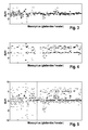
- Fig. 3 2 shows, by way of example, a time profile of the distribution of the values of the lateral position dy corresponding to the direction angles estimated by the individual estimator 22 in an exemplary situation with a preceding vehicle in which the distance from the vehicle (radar object 12) gradually decreases, for example from 120 m to 40 m, while the own vehicle 10 and the preceding vehicle drive in the same lane immediately next to a guardrail.
- the respective, currently determined distribution of the lateral positions dy over the measuring cycles which follow one another in the course of time is shown. The distribution is determined in each case for a sliding window of the measuring cycles.
- Fig. 4 shows in a corresponding representation a determined on the basis of the determined by Zweiziel facilityr 24 direction angle distribution of the lateral positions dy.
- Fig. 5 shows in a corresponding representation the time course of a distribution of the lateral positions dy according to the merged distributions after the 3 and 4 , wherein a balancing weighting of the Einzelielclientr 22 and the Zweielielskyr 24 derived values is made.
- a balancing weighting of the Einzelielclientr 22 and the Zweielielskyr 24 derived values is made.
- a maximum of four directional angles of the individual estimator 22 are present.
- For each measurement cycle only a two-point estimate is performed, so that a maximum of two directional angles of the two-rate estimator 24 are present.
- the values of the single-adder 22 are therefore simple and the values of the two-rate estimator 24 doubly weighted into the distribution determined by the unit 32.
- the object detection unit 30 further comprises a unit 34 arranged to compare the lateral position distribution dy determined by the unit 32 with a model of a position distribution expected from the distance d, taking into account the presence of the object extended along the lane. ie with a model of a lateral position distribution, as expected in the case of the detected presence of a guardrail.
- Fig. 6 shows by way of example four different model phases for the distribution of the lateral positions, which correspond to expected directional angles in the presence of a guardrail, for different distances d from a preceding vehicle.
- the expected occurrence frequency of an estimated lateral position dy is shown in each case.
- a lateral position of the radar object 12 and a lateral position corresponding to a reflection of the radar object 12 on the guardrail 14 are marked by arrows in the illustrated distributions.
- the model phases of the expected distribution of the directional angles which depend on the object distance d can be measured, for example, for the respective radar sensor and stored in the unit 34, for example in the form of characteristic parameters.
- a first model phase due to a high object distance d, the directional angles of radar object 12 and mirror object 18 can not be separated. It is expected a wide, between the angular positions of the radar object 12 and the mirror object 18 uniform distribution without pronounced inner maxima.
- a second model phase which corresponds to a mean object distance d
- relative maxima corresponding to the angular positions of the radar object 12 and the mirror object 18 can be detected.
- the distribution is broad and also includes intermediate values corresponding to ghost objects 19.
- a third model phase which corresponds to a small object distance d, in the distribution the peaks assigned to the radar object 12 and the mirror object 18 are clearly delimited from each other, i. separately. Accordingly, the direction angles of the radar object 12 and the mirror object 18 can be separated from each other.
- the transition between the respective model phases depends essentially on the object distance d and on the directional angle separation capability of the radar sensor 16, but also on the lateral distance dy of the radar object 12 from the guardrail, since at a larger lateral distance dy the angular difference between the radar object 12 and the ghost object 18 is larger.
- the unit 34 recognizes the second model phase as appropriate on the basis of a comparison with the model phases.
- the unit 34 therefore determines the lane side of the guardrail lying lateral position, the right arrow in Fig. 6 corresponds, as a lateral object position dy.
- the lateral object position dy, determined by the unit 34, or a corresponding directional angle ⁇ , is detected by the object detection unit 30 as an object position and output with the relative velocity v and the object distance d, for example, to an object tracking unit 36.
- the object tracking unit 36 is arranged in a manner known per se to track and manage radar objects detected by the radar sensor 16. For example, it is connected to a vehicle speed controller 38 that allows adaptive cruise control.
- the unit 34 recognizes the presence of a situation corresponding to the third model phase.
- the unit 34 therefore determines, as a lateral object position dy, the value of the maximum roadway side of the guardrail and in turn outputs this lateral position dy or a corresponding directional angle ⁇ to the object tracking unit 36.
- the object detection unit 30 can thus improve the object detection by assigning a plurality of initially detected directional angles ⁇ i to only one radar object 12.
- the object detection can thus be improved in particular in situations corresponding to the first or second model phase, since no mirror objects 18 and no ghost objects 19 are included in the object tracking.
- This can also enable improved detection of complex traffic situations, such as one Gull driving between stationary radar objects or a traffic situation with two vehicles driving at approximately the same speed, since such a situation better from the in Fig. 1 illustrated situation can be distinguished.
- the evaluation unit 26 transfers, for example, directly the determined values of the relative velocity v, the object distance d and the direction angle ⁇ i to the object tracking unit 36.
- the evaluation unit 26 and / or the units 30, 32, 34, 36 can be implemented, for example, in the form of algorithms of a digital data processing device.
- Fig. 7 shows a flowchart of a method for detecting radar objects 12 with an angle-resolving radar sensor 16 of a motor vehicle 10 in the presence of a laterally next to the own lane in the direction of travel extended radar waves reflecting object 14.
- the method corresponds for example to the described operation of the basis of Fig. 1 to Fig. 6 explained system.
- the illustrated procedure begins in step 100 with a new measurement cycle of the radar sensor 16, which comprises, for example, four frequency modulation ramps.
- step 102 new measurement data associated with the new measurement cycle are provided, in particular in the case of measured radar reflections from a radar object 12, the relative velocity v, the object distance d and the directional angles ⁇ i . These are provided by the digital signal processing unit 20, for example.
- the measured position distribution is formed over the last measuring cycles, in particular the n last measuring cycles.
- the position distribution may be, for example, the distribution of the lateral position dy or the distribution of the angular positions ⁇ i , ie the direction angle.
- step 106 the measured position distribution is compared with a model of the expected position distribution that depends on the object distance. It should be noted that in the case of a new start of the procedure, the distribution will initially be over the necessary number of measuring cycles is established before a comparison with the model takes place in step 106.
- step 108 based on the comparison made, an object position of a radar object 12 is determined, for example, by the unit 34.
- step 110 of the object tracking or the object management can be followed by a step 110 of the object tracking or the object management, and the method is repeated with, beginning with the step 100 of a new measurement cycle.
Abstract
Description
Die Erfindung betrifft ein System und ein Verfahren zur Detektion von Radarobjekten mit einem winkelauflösenden Radarsensor eines Kraftfahrzeugs in Gegenwart eines seitlich neben der eigenen Fahrspur in Fahrtrichtung ausgedehnten, Radarwellen reflektierenden Gegenstands, wie beispielsweise einer Leitplanke.The invention relates to a system and a method for the detection of radar objects with an angle-resolving radar sensor of a motor vehicle in the presence of a laterally adjacent to the own lane in the direction of travel extended radar waves reflecting object, such as a guardrail.
Radarsensoren werden beispielsweise in ACC-Systemen (Adaptive Cruise Control) für Kraftfahrzeuge eingesetzt und dienen dazu, die Positionen und Relativgeschwindigkeiten von Radarobjekten zu bestimmen, so dass dann im Rahmen einer adaptiven Geschwindigkeitsregelung die Geschwindigkeit des eigenen Fahrzeugs an die Geschwindigkeit eines vorausfahrenden Fahrzeugs angepasst und der Abstand zu dem vorausfahrenden Fahrzeug auf einen geeigneten Wert geregelt werden kann.Radar sensors are used for example in ACC (Adaptive Cruise Control) systems for motor vehicles and serve to determine the positions and relative velocities of radar objects, so then adapted in the context of an adaptive cruise control, the speed of the vehicle to the speed of a preceding vehicle and the Distance to the vehicle in front can be controlled to an appropriate value.
Ein derartiger Radarsensor weist beispielsweise mehrere Kanäle auf, denen jeweils wenigstens ein Antennenelement mit einer jeweiligen Richtcharakteristik und eine Auswerteeinrichtung zugeordnet ist. Die in den verschiedenen Kanälen empfangenen Hochfrequenzsignale werden durch Mischen mit einer Referenzfrequenz, unter Erhaltung der Phasen- und Amplitudenbeziehungen, in Niederfrequenzsignale umgewandelt, die in einer Auswerteelektronik ausgewertet werden. Beispielsweise können die Niederfrequenzsignale mit Analog/Digital-Umsetzern digitalisiert und dann digital weiterverarbeitet werden. Durch Auswertung der Phasenbeziehungen und/oder Auswertung der Amplitudenbeziehungen zwischen den in den verschiedenen Kanälen ist es möglich, den Richtungswinkel eines georteten Radarobjektes zu bestimmen.Such a radar sensor has, for example, a plurality of channels, to each of which at least one antenna element having a respective directional characteristic and an evaluation device are assigned. The radio frequency signals received in the various channels are converted by mixing with a reference frequency, while maintaining the phase and amplitude relationships, in low frequency signals, which are evaluated in an evaluation. For example, the low-frequency signals can be digitized with analog / digital converters and then further processed digitally. By evaluating the phase relationships and / or evaluating the amplitude relationships between the in the different channels, it is possible to determine the direction angle of a located radar object.
Jedes Radarobjekt zeichnet sich im Frequenzspektrum eines Kanals in der Form eines Peaks ab, dessen Lage von der Dopplerverschiebung und damit von der Relativgeschwindigkeit des Radarobjekts abhängig ist. Wenn die Sendefrequenz des Radarsystems moduliert wird, wie beispielsweise bei einem FMCW-Radar (Frequency Modulated Continuous Wave), ist die Lage der Peaks auch von der Laufzeit der Radarsignale abhängig. Wenn das gesendete Signal in einem Messzyklus unterschiedliche, geeignet gewählte Frequenzrampen aufweist, lässt sich aus den Frequenzen der erhaltenen Peaks die Relativgeschwindigkeit des Objekts und der Abstand des Objekts berechnen.Each radar object is characterized in the frequency spectrum of a channel in the form of a peak whose position depends on the Doppler shift and thus on the relative speed of the radar object. When the transmission frequency of the radar system is modulated, as for example in an FMCW (Frequency Modulated Continuous Wave) radar, the position of the peaks is also dependent on the transit time of the radar signals. If the transmitted signal has different suitably selected frequency ramps in a measuring cycle, the relative velocity of the object and the distance of the object can be calculated from the frequencies of the obtained peaks.
In einer Situation mit Mehrwegeausbreitung der Radarsignale, bei der neben direkten Objektreflexionen auch indirekte Objektreflexionen empfangen werden, bei denen von einem zu ortenden Radarobjekt reflektierte Radarsignale beispielsweise an einer Leitplanke seitlich neben der Fahrbahn zusätzlich reflektiert werden, kann die Erkennung von vorausfahrenden Fahrzeugen als Radarobjekte oder als Scheinziele dadurch erschwert oder verhindert werden, dass geschätzte Objektwinkel bzw. Scheinziel-Objektwinkel gestört und verrauscht sind. Die Genauigkeit und Zuverlässigkeit der Winkelbestimmung kann insbesondere bei hohen Entfernungen beeinträchtigt werden. Dadurch kann es beispielsweise vorkommen, dass ein Richtungswinkel eines real existierenden, bewegten Radarobjektes bestimmt wird, der nicht der tatsächlichen Position des Radarobjektes entspricht, sondern einer in Richtung der Leitplanke seitlich versetzten Position entspricht, beispielsweise einer Position zwischen der tatsächlichen Objektposition und einer Scheinziel-Position eines gespiegelten Objektes. Dies kann sich beispielsweise nachteilig auf eine auf der Objekterkennung basierende Abstandsregelfunktion eines adaptiven Fahrgeschwindigkeitsreglers auswirken.In a situation with multipath propagation of the radar signals, in which in addition to direct object reflections and indirect object reflections are received in which radar reflected from a radar object to be detected radar signals, for example, on a guardrail laterally next to the roadway, the detection of preceding vehicles as radar objects or as This makes it difficult or impossible for decoupled targets to be disturbed and noisy estimated object angles or decoupled object angles. The accuracy and reliability of the angle determination can be impaired, especially at high distances. As a result, it may happen, for example, that a directional angle of a real existing, moving radar object is determined, which is not the actual position of the radar object, but corresponds to a laterally offset position in the direction of the guardrail, for example a position between the actual object position and a decoy position of a mirrored object. This may, for example, have a disadvantageous effect on a distance control function of an adaptive cruise control controller based on the object recognition.
Aufgabe der Erfindung ist es, die Detektion von bewegten Radarobjekten in Gegenwart einer Leitplanke oder eines anderen, seitlich neben der eigenen Fahrspur in Fahrtrichtung ausgedehnten, Radarwellen reflektierenden Gegenstandes zu verbessern.The object of the invention is to improve the detection of moving radar objects in the presence of a guardrail or another, laterally next to the own lane in the direction of travel extended radar waves reflecting object.
Ein Beitrag zur Lösung dieser Aufgabe wird erfindungsgemäß durch ein Verfahren der eingangs genannten Art geleistet, mit den Schritten:
- Vergleichen einer gemessenen Positionsverteilung, die einer Verteilung von Richtungswinkeln empfangener, von einem Radarobjekt reflektierter Radarsignale des Radarsensors entspricht, mit einem Modell einer unter Berücksichtigung des Vorhandenseins des neben der eigenen Fahrspur in Fahrtrichtung ausgedehnten Gegenstands erwarteten, von einem Abstand vom Radarobjekt abhängigen Positionsverteilung; und
- Bestimmen einer Position eines Radarobjektes, basierend auf dem Ergebnis des Vergleichs.
- Comparing a measured positional distribution corresponding to a distribution of directional angles of received radar signals of the radar sensor reflected from a radar object with a model of a position distribution expected from a distance from the radar object, taking into account the presence of the object extended next to the own lane; and
- Determining a position of a radar object based on the result of the comparison.
Dabei kann es sich bei dem in Fahrtrichtung ausgedehnten Gegenstand beispielsweise um einen seitlich entlang einer Fahrbahn ausgedehnten Gegenstand handeln, wie etwa eine Leitplanke. Bei der gemessenen Positionsverteilung kann es sich beispielsweise um eine Verteilung einer Winkelposition, insbesondere einem Azimutwinkel, oder um eine Verteilung einer lateralen Position handeln, beispielsweise einer lateralen Position (Querversatz) bezogen auf das eigene Fahrzeug. Indem die gemessene Positionsverteilung mit einem Modell einer Positionsverteilung verglichen wird, können Eigenschaften der Mehrwegeausbreitung der Radarsignale und ihre Auswirkungen auf die empfangenen Signale bei der Auswertung der empfangenen Radarsignale explizit berücksichtigt werden. Die Qualität einer Objektverfolgung, auch als Objekttracking bezeichnet, kann dadurch verbessert werden. So kann es beispielsweise ermöglicht werden, auch bei einer hohen Objektentfernung, bei der anhand der empfangenen Radarsignale ein reales Objekt nicht von einem an einer Leitplanke gespiegelten Spiegelobjekt trennbar ist, das reale Objekt zu detektieren.For example, the object extended in the direction of travel may be an object extended laterally along a roadway, such as a guardrail. The measured position distribution can be, for example, a distribution of an angular position, in particular an azimuth angle, or a distribution of a lateral position, for example a lateral position (transverse offset) relative to the own vehicle. By comparing the measured positional distribution with a model of positional distribution, characteristics of the multipath propagation of the radar signals and their effects on the received signals can be explicitly taken into account in the evaluation of the received radar signals. The quality of object tracking, also referred to as object tracking, can thereby be improved. For example, it is possible to detect the real object even with a high object distance, in which a real object can not be separated from a mirror object mirrored on a guardrail on the basis of the received radar signals.
Das zum Vergleich mit der gemessenen Positionsverteilung herangezogene Modell kann bei einem gegebenen Abstand vom Objekt beispielsweise eine Verteilung einer Winkelposition, insbesondere eines Azimutwinkels, oder eine Verteilung einer lateralen Position beschreiben, beispielsweise einer lateralen Position (Querversatz) bezogen auf das eigene Fahrzeug. Das Modell einer erwarteten Positionsverteilung kann beispielsweise aus einem oder mehreren charakteristischen Merkmalen der erwarteten Positionsverteilung bestehen, oder es kann eine modellierte Positionsverteilung umfassen. Eine modellierte Positionsverteilung kann beispielsweise direkt mit einer gemessenen Positionsverteilung verglichen werden, oder es kann mindestens eine der beiden Positionsverteilungen in einer umgerechneten Form zum Vergleich herangezogen werden.The model used for comparison with the measured position distribution can, for example, describe a distribution of an angular position, in particular of an azimuth angle, or a distribution of a lateral position, for example a lateral position (transverse offset) with respect to the own vehicle, for a given distance from the object. The model of an expected position distribution may for example consist of one or more characteristic features of the expected position distribution, or it may comprise a modeled position distribution. For example, a modeled position distribution can be compared directly with a measured positional distribution, or at least one of the two positional distributions can be used in a converted form for comparison.
Vorzugsweise umfasst das Verfahren, vor dem Schritt des Vergleichens, den Schritt des Bestimmens der gemessenen Positionsverteilung basierend auf einer fortlaufend aktualisierten Historie von Positionen, die Richtungswinkeln empfangener, von dem Radarobjekt reflektierter Radarsignale des Radarsensors entsprechen. Beispielsweise kann in jedem Messzyklus des Radarsensors im Falle einer Objektreflexion wenigstens ein Richtungswinkel bestimmt werden, und die gemessene Positionsverteilung kann Positionen entsprechend den in mehreren Messzyklen gemessenen Richtungswinkeln umfassen. Beispielsweise kann die gemessene Positionsverteilung basierend auf empfangenen Radarsignalen aus den jeweils n letzten Messzyklen bestimmt werden, wobei n eine Zahl ist, die eine Breite eines gleitenden Zeitfensters der Historie der Positionen bestimmt.Preferably, prior to the step of comparing, the method comprises the step of determining the measured position distribution based on a continuously updated history of positions corresponding to direction angles of received radar signals of the radar sensor reflected from the radar object. For example, in each measurement cycle of the radar sensor in the case of object reflection, at least one directional angle may be determined and the measured positional distribution may include positions corresponding to the directional angles measured in several measurement cycles. For example, the measured positional distribution may be determined based on received radar signals from the n most recent measurement cycles, where n is a number that determines a width of a sliding time window of the history of the positions.
Vorzugsweise umfasst das Verfahren weiter den Schritt: Bestimmen einer Modellphase des Modells, basierend auf dem Ergebnis des Vergleichs, wobei die Modellphase bestimmt wird aus mehreren Modellphasen des Modells. Die genannten mehreren Modellphasen können beispielsweise Modellphasen umfassen, die erwarteten Positionsverteilungen entsprechen, die sich in Bezug auf ein Vorhandensein und/oder eine Ausgeprägtheit einer Absenkung der Verteilung in einem Übergangsbereich zwischen Positionen, die einer Position des Radarobjektes und einer Position eines Spiegelobjektes entsprechen, unterscheiden. Die Modellphasen können sich somit in Bezug auf eine Trennbarkeit von Peaks der erwarteten Positionsverteilung unterscheiden, die einer Position des Radarobjektes und einer Position eines Spiegelobjektes entsprechen. Beispielsweise kann in wenigstens einer Modellphase eine zumindest zwischen einer Position des Radarobjektes und einer Position eines Spiegelobjektes gleichförmig streuende Positionsverteilung erwartet werden, und in wenigstens einer Modellphase kann eine Positionsverteilung mit zwei getrennten, jeweils einer Position des Radarobjektes und einer Position eines Spiegelobjektes entsprechenden Peaks erwartet werden, wobei letztere Positionsverteilung bei einem kleineren Abstand vom Radarobjekt erwartet wird als die zuvor genannte Positionsverteilung.Preferably, the method further comprises the step of: determining a model phase of the model based on the result of the comparison, wherein the model phase is determined from several model phases of the model. For example, said plurality of model phases may include model phases corresponding to expected position distributions differing in existence and / or expressiveness of lowering the distribution in a transitional region between positions corresponding to a position of the radar object and a position of a mirror object. The model phases may thus differ in terms of separability from expected position distribution peaks corresponding to a position of the radar object and a position of a mirror object. For example, in at least one model phase, a position distribution uniformly scattering at least between a position of the radar object and a position of a mirror object can be expected, and in at least one model phase For example, a positional distribution with two separate peaks, each corresponding to a position of the radar object and a position of a mirror object, can be expected, the latter position distribution being expected at a smaller distance from the radar object than the aforementioned positional distribution.
Die genannten mehreren Modellphasen können beispielsweise Modellphasen umfassen, die erwarteten Positionsverteilungen entsprechen, die jeweils eine Streuung von Werten der Verteilung um eine Position entsprechend einem Radarobjekt und um eine Position entsprechend einem Spiegelobjekt aufweisen und sich hinsichtlich einer von dem Abstand vom Radarobjekt abhängigen Streubreite unterscheiden.For example, said plurality of model phases may include model phases corresponding to expected position distributions each having a distribution of values of distribution around a position corresponding to a radar object and about a position corresponding to a mirror object and differing in a spread depending on the distance from the radar object.
Weiter wird ein Beitrag zur Lösung der genannten Aufgabe erfindungsgemäß durch eine System zur Detektion von Radarobjekten mit einem winkelauflösenden Radarsensor eines Kraftfahrzeugs in Gegenwart eines seitlich neben der eigenen Fahrspur in Fahrtrichtung ausgedehnten, Radarwellen reflektierenden Gegenstands geleistet, wobei das System aufweist:
- eine Einheit, die dazu eingerichtet ist, eine gemessene Positionsverteilung zu bestimmen, die eine Verteilung von Richtungswinkeln empfangener, von einem Radarobjekt reflektierter Radarsignale des Radarsensors entspricht,
- eine Einheit, die dazu eingerichtet ist, die gemessene Positionsverteilung mit einem Modell einer unter Berücksichtigung des Vorhandenseins des neben der eigenen Fahrspur in Fahrtrichtung ausgedehnten Gegenstands erwarteten, von einem Abstand vom Radarobjekt abhängigen Positionsverteilung zu vergleichen; und
- eine Einheit, die dazu eingerichtet ist, basierend auf dem Ergebnis des Vergleichs eine Position eines Radarobjektes zu bestimmen.
- a unit configured to determine a measured positional distribution corresponding to a distribution of directional angles of received radar signals of the radar sensor reflected from a radar object;
- a unit arranged to compare the measured positional distribution with a model of a positional distribution expected from a distance from the radar object, taking into account the presence of the object extended next to the own lane in the direction of travel; and
- a unit configured to determine a position of a radar object based on the result of the comparison.
Weitere vorteilhafte Ausgestaltungen der Erfindung sind jeweils in den Unteransprüchen angegeben.Further advantageous embodiments of the invention are specified in the dependent claims.
Ausführungsbeispiele der Erfindung sind in den Zeichnungen dargestellt und in der nachfolgenden Beschreibung näher erläutert.Embodiments of the invention are illustrated in the drawings and explained in more detail in the following description.
Es zeigen:
- Fig. 1
- eine schematische Darstellung einer Verkehrssituation mit Mehrwegereflexion von Radarsignalen von einem Radarobjekt;
- Fig. 2
- ein schematisches Blockschaltbild eines Kraftfahrzeug-Sensorsystems;
- Fig. 3 bis 5
- schematische Darstellungen von gemessenen Positionsverteilungen, die Richtungswinkeln empfangener Radarsignale entsprechen;
- Fig. 6
- eine schematische Darstellung von Modellphasen eines Modells für eine Positionsverteilung; und
- Fig. 7
- ein Ablaufdiagramm einer Ausführungsform eines Verfahrens zur Objektdetektion.
- Fig. 1
- a schematic representation of a traffic situation with Mehrwegereflexion of radar signals from a radar object;
- Fig. 2
- a schematic block diagram of a motor vehicle sensor system;
- Fig. 3 to 5
- schematic representations of measured position distributions corresponding to direction angles of received radar signals;
- Fig. 6
- a schematic representation of model phases of a model for a position distribution; and
- Fig. 7
- a flowchart of an embodiment of a method for object detection.
Das Fahrzeug 10 ist mit einem winkelauflösenden Radarsensor 16 ausgestattet, der im Frontbereich des Fahrzeugs 10 angeordnet ist und dazu eingerichtet ist, Radarobjekte in einem Sensorerfassungsbereich vor dem eigenen Fahrzeug 10 zu detektieren. Beispielsweise handelt es sich um einen FMCW-Radarsensor, bei dem die Frequenz eines gesendeten Radarsignals periodisch moduliert wird, insbesondere in Form wenigstens einer Frequenzrampe, beispielsweise vier Rampen je Messzyklus. Der Radarsensor 16 hat mehrere Antennenelemente mit unterschiedlichen Richtcharakteristiken, die eine Bestimmung eines Richtungswinkels eines empfangenen Radarsignals gestatten.The
Der Radarsensor 16 ist beispielsweise dazu eingerichtet, basierend auf empfangenen, von einem Radarobjekt 12 reflektierten Radarsignalen des Radarsensors 16 den in einem Messzyklus des Radarsensors 16 empfangenen Radarsignalen jeweils wenigstens einen Richtungswinkel zuzuordnen, aus dem das Radarsignal empfangen wird. Wenn bei größeren Entfernungen zwischen dem eigenen Fahrzeug 10 und dem zu ortenden Radarobjekt 12 die Trennfähigkeit des Radarsensors 16 bezüglich des Richtungswinkels der empfangenen Radarsignale abnimmt, kann es dazu kommen, dass den empfangenen Objektreflexionen Richtungswinkel zugeordnet werden, die von den tatsächlichen Richtungswinkels des Radarobjektes 12 und des Spiegelobjektes 18 abweichen und insbesondere einer Position eines sogenannten Geisterobjekts 19 in einem Winkelbereich zwischen dem Radarobjekt 12 und dem Spiegelobjekt 18 entsprechen können.The
Die Signalverarbeitungseinheit 20 umfasst einen Einzielschätzer 22, der dazu eingerichtet ist, für jede Frequenzrampe eines Messzyklus einen Richtungswinkel eines Radarechos zu bestimmen. Beispielsweise werden normierte Amplituden und Phasen von Peaks der Zwischenfrequenzsignale mit entsprechenden Antennendiagrammen für die Antennenelemente des Radarsensors 16 abgeglichen, so dass sich anhand einer bekannten Winkelabhängigkeit der Amplituden und Phasen die Azimutwinkel der georteten Objekte bestimmen lassen. Hierzu wird ein eindimensionaler, d.h. in Abhängigkeit des Winkels berechneter Suchraum von Amplituden- und Phasendifferenzen durchsucht, um eine Korrelation zwischen dem gemessenen Signal und einem für einen Winkel erwarteten Signal aufzufinden. Ein Peak der Korrelation kennzeichnet dann den wahrscheinlichsten Wert des Azimutwinkels.The
Weiter umfasst die Signalverarbeitungseinheit 20 optional einen Zweizielschätzer 24, der dazu eingerichtet ist, für wenigstens eine Frequenzrampe in einem Messzyklus zwei Richtungswinkel eines Radarechos zu bestimmen, wenn sich die Objektreflexion zwei Radarobjekten an unterschiedlichen Winkelpositionen zuordnen lässt. Hierzu wird ein zweidimensionaler, d.h. in Abhängigkeit eines ersten Winkels und eines zweiten Winkels berechneter Suchraum durchsucht, um eine Korrelation zwischen dem gemessenen Signal und einem für eine Kombination von Winkeln erwarteten Signal aufzufinden.Furthermore, the
Der Einzielschätzer 22 und der Zweizielschätzer 24 können beispielsweise als Algorithmus in der Signalverarbeitungseinheit 20 implementiert sein kann.The single-
Zu jedem Messzyklus werden die im Falle von Objektreflexionen ermittelten Werte der Relativgeschwindigkeit v, des Objektabstands d und der geschätzten Richtungswinkel θi, mit i = 1, ..., N+2, an eine Auswertungseinheit 26 ausgegeben. Die Anzahl der Richtungswinkel beträgt N Einzielschätzungen zuzüglich zwei Richtungswinkel für eine Zweizielschätzung.For each measurement cycle, the values of the relative velocity v, the object distance d and the estimated directional angle θ i , with i = 1,..., N + 2, determined in the case of object reflections, are output to an
Die Auswertungseinheit 26 umfasst optional eine Einrichtung 28 zur Erkennung einer Anwesenheit eines seitlich neben der eigenen Fahrspur in Fahrtrichtung ausgedehnten Gegenstandes 14, der von Radarobjekten reflektierte Radarsignale des Radarsensors zusätzlich reflektiert, wie beispielsweise einer Leitplanke. Die Einrichtung 28 erkennt beispielsweise die Anwesenheit einer Leitplanke an dem Auftreten von Radarechos einer Folge von Pfosten der Leitplanke. Pfosten einer Leitplanke stellen gut detektierbare Radarobjekte dar. Darüber hinaus kann Information über den seitlichen Abstand zur Leitplanke gewonnen werden. Im Falle der erkannten Anwesenheit einer Leitplanke oder eines ähnlichen, Radarwellen reflektierenden Gegenstandes 14 entlang der Fahrbahn oder seitlich neben der eigenen Fahrspur wird eine Objektdetektionseinheit 30 aktiviert, die dazu eingerichtet ist, Positionen von Radarobjekten unter Berücksichtigung der durch den Gegenstand 14 hervorgerufene Situation einer Mehrfachreflexion zu bestimmen.The
Die Objektdetektionseinheit 30 umfasst eine Einheit 32, die dazu eingerichtet ist, basierend auf den Richtungswinkeln θi und dem Objektabstand d eine Positionsverteilung lateraler Positionen dy zu bestimmen, die einer Verteilung der Richtungswinkel θi entspricht. Dazu werden die Richtungswinkel θi über den Objektabstand d in laterale Positionen dy bezogen auf die Längsachse des eigenen Fahrzeugs umgewandet. Die Verteilung wird beispielsweise jeweils aus einer Historie von ermittelten lateralen Positionen dy aus den n letzten Messzyklen bestimmt, wobei beispielsweise n = 5 oder n = 10 gewählt wird. Allgemein wird die Anzahl n der berücksichtigten Messzyklen so gewählt, dass in gewöhnlichen Fahrsituationen die Relativpositionen erfasster Fahrzeuge im wesentlichen unverändert bleiben. Es wird dabei von der Annahme ausgegangen, dass der laterale Abstand des Radarobjektes 12 zur Leitplanke sich nur langsam verändert und somit in dem betrachteten gleitenden Fenster der letzten Messzyklen im wesentlichen unverändert ist.The
Die Objektdetektionseinheit 30 umfasst weiter eine Einheit 34, die dazu eingerichtet ist, die von der Einheit 32 bestimmte Verteilung der lateralen Position dy mit einem Modell einer unter Berücksichtigung des Vorhandenseins des entlang der Fahrbahn ausgedehnten Gegenstands erwarteten, von dem Abstand d abhängigen Positionsverteilung zu vergleichen, d.h. mit einem Modell einer lateralen Positionsverteilung, wie sie im Falle der erkannten Anwesenheit einer Leitplanke zu erwarten ist.The
In einer ersten Modellphase sind aufgrund eines hohen Objektabstandes d die Richtungswinkel von Radarobjekt 12 und Spiegelobjekt 18 nicht trennbar. Es wird eine breite, zwischen den Winkelpositionen des Radarobjektes 12 und des Spiegelobjektes 18 gleichförmige Verteilung ohne ausgeprägte innere Maxima erwartet.In a first model phase, due to a high object distance d, the directional angles of
In einer zweiten Modellphase, die einem mittleren Objektabstand d entspricht, können relative Maxima entsprechend den Winkelpositionen des Radarobjektes 12 und des Spiegelobjektes 18 erkannt werden. Die Verteilung streut jedoch breit und umfasst auch Zwischenwerte entsprechend Geisterobjekten 19.In a second model phase, which corresponds to a mean object distance d, relative maxima corresponding to the angular positions of the
In einer dritten Modellphase, die einem geringen Objektabstand d entspricht, sind in der Verteilung die dem Radarobjekt 12 und dem Spiegelobjekt 18 zugeordneten Peaks deutlich voneinander abgegrenzt, d.h. separat. Entsprechend können die Richtungswinkel des Radarobjekts 12 und der Spiegelobjekts 18 voneinander getrennt werden.In a third model phase, which corresponds to a small object distance d, in the distribution the peaks assigned to the
Der Übergang zwischen den jeweiligen Modellphasen hängt im wesentlichen vom Objektabstand d und von der Richtungswinkel-Trennfähigkeit des Radarsensors 16 ab, darüber hinaus aber auch von dem lateralen Abstand dy des Radarobjektes 12 von der Leitplanke, da bei größerem seitlichem Abstand dy der Winkelunterschied zwischen dem Radarobjekt 12 und dem Geisterobjekt 18 größer ist.The transition between the respective model phases depends essentially on the object distance d and on the directional angle separation capability of the
In einem vierten Modell, das einem Nahbereich mit noch geringerem Objektabstand d entspricht, werden keine indirekten Objektreflexionen von der Leitplanke empfangen. In der Verteilung der lateralen Positionen dy ergibt sich nur ein Peak entsprechend dem Richtungswinkel des Radarobjektes 12.In a fourth model, which corresponds to a near zone with even smaller object distance d, no indirect object reflections are received by the guardrail. In the distribution of the lateral positions dy, only one peak results according to the directional angle of the
In
Die Einheit 34 erkennt hier aufgrund eines Vergleichs mit den Modellphasen die zweite Modellphase als zutreffend. Die Einheit 34 bestimmt daher die fahrbahnseitig der Leitplanke liegende laterale Position, die dem rechten Pfeil in
In den in
Durch die Objektdetektionseinheit 30 kann somit bei erkannter Anwesenheit einer Leitplanke die Objektdetektion verbessert werden, indem mehrere zunächst detektierte Richtungswinkel θi nur einem Radarobjekt 12 zugeordnet werden. Die Objektdetektion kann somit insbesondere in Situationen entsprechend der ersten oder zweiten Modellphase verbessert werden, da keine Spiegelobjekte 18 und keine Geisterobjekte 19 in das Objekttracking aufgenommen werden. Dies kann darüber hinaus eine verbesserte Erkennung von komplexen Verkehrssituationen ermöglichen, beispielsweise einer Gassenfahrt zwischen stehenden Radarobjekten oder einer Verkehrssituation mit zwei mit annähernd gleicher Geschwindigkeit vorausfahrenden Fahrzeugen, da eine solche Situation besser von der in
In Situationen ohne Mehrfachreflexion, oder wenn bei einer Variante ohne die Einrichtung 28 die Objektdetektionseinheit 30 keines der beschriebenen Modelle als zutreffend erkannt hat, erfolgt durch die Auswertungseinheit 26 beispielsweise direkt eine Weitergabe der ermittelten Werte der Relativgeschwindigkeit v, des Objektabstands d und der Richtungswinkel θi an die Objekttracking-Einheit 36.In situations without multiple reflection, or if, in a variant without the
Die Auswertungseinheit 26 und/oder die Einheiten 30, 32, 34, 36 können beispielsweise in Form von Algorithmen einer digitalen Datenverarbeitungseinrichtung implementiert sein.The
Der dargestellte Ablauf beginnt in Schritt 100 mit einem neuen Messzyklus des Radarsensors 16, der beispielsweise vier Frequenzmodulationsrampen umfasst.The illustrated procedure begins in
In Schritt 102 werden dem neuen Messzyklus zugehörige, neue Messdaten bereitgestellt, insbesondere im Falle von gemessenen Radarreflexionen von einem Radarobjekt 12 die Relativgeschwindigkeit v, der Objektabstand d und die Richtungswinkel θi. Diese werden beispielsweise von der digitalen Signalverarbeitungseinheit 20 zur Verfügung gestellt.In
In Schritt 104 wird die gemessene Positionsverteilung über die letzten Messzyklen, insbesondere die n letzten Messzyklen, gebildet. Bei der Positionsverteilung kann es sich beispielsweise um die Verteilung der lateralen Position dy oder um die Verteilung der Winkelpositionen θi, d.h. der Richtungswinkel, handeln.In
In Schritt 106 erfolgt ein Vergleich der gemessenen Positionsverteilung mit einem Modell der vom Objektabstand abhängigen, erwarteten Positionsverteilung. Es ist anzumerken, dass die Verteilung im Falle eines Neubeginns des Verfahrens zunächst über die notwendige Anzahl von Messzyklen aufgebaut wird, bevor in Schritt 106 ein Vergleich mit dem Modell erfolgt.In
In Schritt 108 wird, basierend auf dem durchgeführten Vergleich, eine Objektposition eines Radarobjektes 12 bestimmt, beispielsweise durch die Einheit 34.In
Daran kann sich ein Schritt 110 des Objekttrackings bzw. der Objektverwaltung anschließen, und das Verfahren wird mit, beginnend mit dem Schritt 100 eines neuen Messzyklus, wiederholt.This can be followed by a
Claims (10)
Applications Claiming Priority (1)
| Application Number | Priority Date | Filing Date | Title |
|---|---|---|---|
| DE102012208852A DE102012208852A1 (en) | 2012-05-25 | 2012-05-25 | Detection of radar objects with a radar sensor of a motor vehicle |
Publications (2)
| Publication Number | Publication Date |
|---|---|
| EP2667219A1 true EP2667219A1 (en) | 2013-11-27 |
| EP2667219B1 EP2667219B1 (en) | 2017-09-27 |
Family
ID=48044621
Family Applications (1)
| Application Number | Title | Priority Date | Filing Date |
|---|---|---|---|
| EP13161284.8A Active EP2667219B1 (en) | 2012-05-25 | 2013-03-27 | Detection of radar objects with a radar sensor of a motor vehicle |
Country Status (3)
| Country | Link |
|---|---|
| US (1) | US9229098B2 (en) |
| EP (1) | EP2667219B1 (en) |
| DE (1) | DE102012208852A1 (en) |
Cited By (4)
| Publication number | Priority date | Publication date | Assignee | Title |
|---|---|---|---|---|
| CN107179530A (en) * | 2016-03-11 | 2017-09-19 | 罗伯特·博世有限公司 | For the device for the imbalance for asking for being fixed on the detecting devices on vehicle |
| WO2018104468A1 (en) * | 2016-12-08 | 2018-06-14 | Iee International Electronics & Engineering S.A. | Direction of arrival estimation for automotive spread radar systems |
| LU100130B1 (en) * | 2017-03-02 | 2018-09-07 | Iee Sa | Direction of Arrival Estimation with Automotive Spread Radar Systems |
| WO2022033980A1 (en) | 2020-08-11 | 2022-02-17 | Bayerische Motoren Werke Aktiengesellschaft | Method for recognizing road users in an environment of a vehicle on the basis of measurements of a radar sensor, by identifying faulty detections, and computing device |
Families Citing this family (20)
| Publication number | Priority date | Publication date | Assignee | Title |
|---|---|---|---|---|
| JP6432221B2 (en) * | 2014-01-15 | 2018-12-05 | パナソニック株式会社 | Radar equipment |
| JP6352681B2 (en) * | 2014-05-29 | 2018-07-04 | 株式会社デンソーテン | Radar apparatus, vehicle control system, and signal processing method |
| CN107004360B (en) * | 2014-07-03 | 2020-08-07 | 通用汽车环球科技运作有限责任公司 | Vehicle radar method and system |
| EP3164860A4 (en) | 2014-07-03 | 2018-01-17 | GM Global Technology Operations LLC | Vehicle cognitive radar methods and systems |
| DE102015101292A1 (en) * | 2015-01-29 | 2016-08-04 | Valeo Schalter Und Sensoren Gmbh | Method for detecting an object in an environmental region of a motor vehicle by checking a spatial deviation of measuring points, control device, driver assistance system and motor vehicle |
| US9810782B2 (en) * | 2015-03-20 | 2017-11-07 | Delphi Technologies, Inc. | Vehicle radar system with image reflection detection |
| JP6531903B2 (en) * | 2015-06-01 | 2019-06-19 | パナソニックIpマネジメント株式会社 | Object detection device |
| JP6531698B2 (en) * | 2016-04-01 | 2019-06-19 | トヨタ自動車株式会社 | Approach vehicle notification device |
| DE102016215509A1 (en) | 2016-08-18 | 2018-02-22 | Conti Temic Microelectronic Gmbh | Mirror target detection in a radar system in a vehicle |
| US10605897B2 (en) | 2018-03-06 | 2020-03-31 | Veoneer Us, Inc. | Vehicle lane alignment correction improvements |
| DE102018009122A1 (en) * | 2018-11-20 | 2020-05-20 | Zf Active Safety Gmbh | Control system and control method for determining environmental information |
| US11255958B2 (en) | 2019-02-28 | 2022-02-22 | Zoox, Inc. | Recognizing radar reflections using velocity information |
| US11353578B2 (en) * | 2019-02-28 | 2022-06-07 | Zoox, Inc. | Recognizing radar reflections using position information |
| CN110596660B (en) * | 2019-10-09 | 2023-03-21 | 立晟智能科技(成都)有限公司 | Method and system for improving accuracy of radar measurement object size |
| CN111289980B (en) * | 2020-03-06 | 2022-03-08 | 成都纳雷科技有限公司 | Roadside stationary object detection method and system based on vehicle-mounted millimeter wave radar |
| KR102332509B1 (en) * | 2020-05-22 | 2021-11-29 | 현대모비스 주식회사 | Method and apparatus for rear cross collision warning |
| CN112835026B (en) * | 2020-12-31 | 2024-02-20 | 福瑞泰克智能系统有限公司 | Radar mirror image target detection method and device, radar equipment and vehicle |
| US11754674B2 (en) * | 2021-02-04 | 2023-09-12 | Intel Corporation | Apparatus, system, and method of generating radar target information |
| CN113009448B (en) * | 2021-03-09 | 2022-12-06 | 森思泰克河北科技有限公司 | Method, device, equipment and storage medium for detecting multipath target |
| CN113514825A (en) * | 2021-04-23 | 2021-10-19 | 芜湖森思泰克智能科技有限公司 | Road edge obtaining method and device and terminal equipment |
Citations (3)
| Publication number | Priority date | Publication date | Assignee | Title |
|---|---|---|---|---|
| WO2006010662A1 (en) * | 2004-07-28 | 2006-02-02 | Robert Bosch Gmbh | Method and device for detecting objects, used in a vehicle |
| JP2009079917A (en) * | 2007-09-25 | 2009-04-16 | Denso Corp | Method and apparatus for detecting vehicle width, and device for controlling vehicle |
| US20120119937A1 (en) * | 2009-07-29 | 2012-05-17 | Toyota Jidosha Kabushiki Kaisha | Radar device |
Family Cites Families (2)
| Publication number | Priority date | Publication date | Assignee | Title |
|---|---|---|---|---|
| CN100504437C (en) * | 2003-11-18 | 2009-06-24 | 株式会社村田制作所 | Radar |
| US9129211B2 (en) * | 2012-03-15 | 2015-09-08 | GM Global Technology Operations LLC | Bayesian network to track objects using scan points using multiple LiDAR sensors |
-
2012
- 2012-05-25 DE DE102012208852A patent/DE102012208852A1/en not_active Withdrawn
-
2013
- 2013-03-27 EP EP13161284.8A patent/EP2667219B1/en active Active
- 2013-05-20 US US13/898,168 patent/US9229098B2/en not_active Expired - Fee Related
Patent Citations (4)
| Publication number | Priority date | Publication date | Assignee | Title |
|---|---|---|---|---|
| WO2006010662A1 (en) * | 2004-07-28 | 2006-02-02 | Robert Bosch Gmbh | Method and device for detecting objects, used in a vehicle |
| DE102004036580A1 (en) | 2004-07-28 | 2006-03-16 | Robert Bosch Gmbh | Method and device for object detection in a vehicle |
| JP2009079917A (en) * | 2007-09-25 | 2009-04-16 | Denso Corp | Method and apparatus for detecting vehicle width, and device for controlling vehicle |
| US20120119937A1 (en) * | 2009-07-29 | 2012-05-17 | Toyota Jidosha Kabushiki Kaisha | Radar device |
Cited By (7)
| Publication number | Priority date | Publication date | Assignee | Title |
|---|---|---|---|---|
| CN107179530A (en) * | 2016-03-11 | 2017-09-19 | 罗伯特·博世有限公司 | For the device for the imbalance for asking for being fixed on the detecting devices on vehicle |
| WO2018104468A1 (en) * | 2016-12-08 | 2018-06-14 | Iee International Electronics & Engineering S.A. | Direction of arrival estimation for automotive spread radar systems |
| CN110062892A (en) * | 2016-12-08 | 2019-07-26 | Iee国际电子工程股份公司 | For the estimation of the arrival direction of automobile extension radar system |
| US10884113B2 (en) | 2016-12-08 | 2021-01-05 | Iee International Electronics & Engineering S.A. | Direction of arrival estimation for automotive spread radar systems |
| LU100130B1 (en) * | 2017-03-02 | 2018-09-07 | Iee Sa | Direction of Arrival Estimation with Automotive Spread Radar Systems |
| WO2022033980A1 (en) | 2020-08-11 | 2022-02-17 | Bayerische Motoren Werke Aktiengesellschaft | Method for recognizing road users in an environment of a vehicle on the basis of measurements of a radar sensor, by identifying faulty detections, and computing device |
| DE102020121108A1 (en) | 2020-08-11 | 2022-02-17 | Bayerische Motoren Werke Aktiengesellschaft | Method for detecting road users in the vicinity of a vehicle based on measurements from a radar sensor by identifying interference detections, and computing device |
Also Published As
| Publication number | Publication date |
|---|---|
| US20130314272A1 (en) | 2013-11-28 |
| US9229098B2 (en) | 2016-01-05 |
| DE102012208852A1 (en) | 2013-11-28 |
| EP2667219B1 (en) | 2017-09-27 |
Similar Documents
| Publication | Publication Date | Title |
|---|---|---|
| EP2667219B1 (en) | Detection of radar objects with a radar sensor of a motor vehicle | |
| EP2674776B1 (en) | Indicator to determine whether an object can be driven over | |
| EP2999975B1 (en) | Determination of an elevation misalignment angle of a radar sensor of a motor vehicle | |
| EP3161510B1 (en) | Radar measuring method | |
| EP1929331B1 (en) | Motor vehicle wheel behaviour and radar system | |
| EP1864155B1 (en) | Method and device for measuring distance and relative speed of a plurality of objects | |
| EP1554602B1 (en) | Method for measuring distances and speeds of several objects by means of an fmcw radar | |
| EP1797448B1 (en) | Object verification method in radar systems for motor vehicles | |
| EP2569650B1 (en) | Method and apparatus for determining the position of an object relative to a vehicle, in particular a motor vehicle, for use in a driver assistance system for the vehicle | |
| EP2073038B1 (en) | Method of classifying distance data and the corresponding distance measuring device | |
| DE102016222776B4 (en) | Radar device for vehicles and target determination method therefor | |
| DE102010029699A1 (en) | Radar sensor and method for detecting precipitation with a radar sensor | |
| DE102014110667A1 (en) | Method for classifying an object in a surrounding area of a motor vehicle, driver assistance system and motor vehicle | |
| WO2015197229A1 (en) | Method for locating an object using an fmcw radar | |
| EP2698648A1 (en) | Method for classifying vehicles in motion | |
| DE102015105080B4 (en) | radar device | |
| DE102013209736A1 (en) | Method for evaluating obstacles in a driver assistance system for motor vehicles | |
| DE102017111893A1 (en) | Radar device and control method for radar device | |
| DE102010030289A1 (en) | Radar sensor and method for operating a radar sensor | |
| DE102014202752B4 (en) | Detection of dynamic objects by means of ultrasound | |
| DE102009001243A1 (en) | Method for detecting icing in an angle-resolving radar sensor in an angle-resolving radar sensor in a driver assistance system for motor vehicles | |
| EP3596489A1 (en) | Method and radar device for determining radial relative acceleration of at least one target | |
| DE102016225494B4 (en) | METHOD AND DEVICE FOR DETECTING A TARGET OBJECT | |
| EP2065727A1 (en) | Method for estimating the width of radar objects | |
| DE102013008953A1 (en) | Method for operating a radar device of a vehicle, in particular of a motor vehicle, and radar device for a vehicle, in particular a motor vehicle |
Legal Events
| Date | Code | Title | Description |
|---|---|---|---|
| PUAI | Public reference made under article 153(3) epc to a published international application that has entered the european phase |
Free format text: ORIGINAL CODE: 0009012 |
|
| AK | Designated contracting states |
Kind code of ref document: A1 Designated state(s): AL AT BE BG CH CY CZ DE DK EE ES FI FR GB GR HR HU IE IS IT LI LT LU LV MC MK MT NL NO PL PT RO RS SE SI SK SM TR |
|
| AX | Request for extension of the european patent |
Extension state: BA ME |
|
| 17P | Request for examination filed |
Effective date: 20140527 |
|
| RBV | Designated contracting states (corrected) |
Designated state(s): AL AT BE BG CH CY CZ DE DK EE ES FI FR GB GR HR HU IE IS IT LI LT LU LV MC MK MT NL NO PL PT RO RS SE SI SK SM TR |
|
| 17Q | First examination report despatched |
Effective date: 20160502 |
|
| REG | Reference to a national code |
Ref country code: DE Ref legal event code: R079 Ref document number: 502013008421 Country of ref document: DE Free format text: PREVIOUS MAIN CLASS: G01S0013930000 Ipc: G01S0013060000 |
|
| GRAP | Despatch of communication of intention to grant a patent |
Free format text: ORIGINAL CODE: EPIDOSNIGR1 |
|
| RIC1 | Information provided on ipc code assigned before grant |
Ipc: G01S 13/93 20060101ALI20170217BHEP Ipc: G01S 13/06 20060101AFI20170217BHEP |
|
| INTG | Intention to grant announced |
Effective date: 20170309 |
|
| GRAS | Grant fee paid |
Free format text: ORIGINAL CODE: EPIDOSNIGR3 |
|
| GRAA | (expected) grant |
Free format text: ORIGINAL CODE: 0009210 |
|
| AK | Designated contracting states |
Kind code of ref document: B1 Designated state(s): AL AT BE BG CH CY CZ DE DK EE ES FI FR GB GR HR HU IE IS IT LI LT LU LV MC MK MT NL NO PL PT RO RS SE SI SK SM TR |
|
| REG | Reference to a national code |
Ref country code: GB Ref legal event code: FG4D Free format text: NOT ENGLISH |
|
| REG | Reference to a national code |
Ref country code: CH Ref legal event code: EP |
|
| REG | Reference to a national code |
Ref country code: AT Ref legal event code: REF Ref document number: 932451 Country of ref document: AT Kind code of ref document: T Effective date: 20171015 |
|
| REG | Reference to a national code |
Ref country code: IE Ref legal event code: FG4D Free format text: LANGUAGE OF EP DOCUMENT: GERMAN |
|
| REG | Reference to a national code |
Ref country code: DE Ref legal event code: R096 Ref document number: 502013008421 Country of ref document: DE |
|
| REG | Reference to a national code |
Ref country code: SE Ref legal event code: TRGR |
|
| PG25 | Lapsed in a contracting state [announced via postgrant information from national office to epo] |
Ref country code: NO Free format text: LAPSE BECAUSE OF FAILURE TO SUBMIT A TRANSLATION OF THE DESCRIPTION OR TO PAY THE FEE WITHIN THE PRESCRIBED TIME-LIMIT Effective date: 20171227 Ref country code: HR Free format text: LAPSE BECAUSE OF FAILURE TO SUBMIT A TRANSLATION OF THE DESCRIPTION OR TO PAY THE FEE WITHIN THE PRESCRIBED TIME-LIMIT Effective date: 20170927 Ref country code: LT Free format text: LAPSE BECAUSE OF FAILURE TO SUBMIT A TRANSLATION OF THE DESCRIPTION OR TO PAY THE FEE WITHIN THE PRESCRIBED TIME-LIMIT Effective date: 20170927 Ref country code: FI Free format text: LAPSE BECAUSE OF FAILURE TO SUBMIT A TRANSLATION OF THE DESCRIPTION OR TO PAY THE FEE WITHIN THE PRESCRIBED TIME-LIMIT Effective date: 20170927 |
|
| REG | Reference to a national code |
Ref country code: NL Ref legal event code: MP Effective date: 20170927 |
|
| REG | Reference to a national code |
Ref country code: LT Ref legal event code: MG4D |
|
| PG25 | Lapsed in a contracting state [announced via postgrant information from national office to epo] |
Ref country code: GR Free format text: LAPSE BECAUSE OF FAILURE TO SUBMIT A TRANSLATION OF THE DESCRIPTION OR TO PAY THE FEE WITHIN THE PRESCRIBED TIME-LIMIT Effective date: 20171228 Ref country code: BG Free format text: LAPSE BECAUSE OF FAILURE TO SUBMIT A TRANSLATION OF THE DESCRIPTION OR TO PAY THE FEE WITHIN THE PRESCRIBED TIME-LIMIT Effective date: 20171227 Ref country code: RS Free format text: LAPSE BECAUSE OF FAILURE TO SUBMIT A TRANSLATION OF THE DESCRIPTION OR TO PAY THE FEE WITHIN THE PRESCRIBED TIME-LIMIT Effective date: 20170927 Ref country code: LV Free format text: LAPSE BECAUSE OF FAILURE TO SUBMIT A TRANSLATION OF THE DESCRIPTION OR TO PAY THE FEE WITHIN THE PRESCRIBED TIME-LIMIT Effective date: 20170927 |
|
| REG | Reference to a national code |
Ref country code: FR Ref legal event code: PLFP Year of fee payment: 6 |
|
| PG25 | Lapsed in a contracting state [announced via postgrant information from national office to epo] |
Ref country code: NL Free format text: LAPSE BECAUSE OF FAILURE TO SUBMIT A TRANSLATION OF THE DESCRIPTION OR TO PAY THE FEE WITHIN THE PRESCRIBED TIME-LIMIT Effective date: 20170927 |
|
| PG25 | Lapsed in a contracting state [announced via postgrant information from national office to epo] |
Ref country code: ES Free format text: LAPSE BECAUSE OF FAILURE TO SUBMIT A TRANSLATION OF THE DESCRIPTION OR TO PAY THE FEE WITHIN THE PRESCRIBED TIME-LIMIT Effective date: 20170927 Ref country code: CZ Free format text: LAPSE BECAUSE OF FAILURE TO SUBMIT A TRANSLATION OF THE DESCRIPTION OR TO PAY THE FEE WITHIN THE PRESCRIBED TIME-LIMIT Effective date: 20170927 Ref country code: RO Free format text: LAPSE BECAUSE OF FAILURE TO SUBMIT A TRANSLATION OF THE DESCRIPTION OR TO PAY THE FEE WITHIN THE PRESCRIBED TIME-LIMIT Effective date: 20170927 |
|
| PG25 | Lapsed in a contracting state [announced via postgrant information from national office to epo] |
Ref country code: SK Free format text: LAPSE BECAUSE OF FAILURE TO SUBMIT A TRANSLATION OF THE DESCRIPTION OR TO PAY THE FEE WITHIN THE PRESCRIBED TIME-LIMIT Effective date: 20170927 Ref country code: SM Free format text: LAPSE BECAUSE OF FAILURE TO SUBMIT A TRANSLATION OF THE DESCRIPTION OR TO PAY THE FEE WITHIN THE PRESCRIBED TIME-LIMIT Effective date: 20170927 Ref country code: EE Free format text: LAPSE BECAUSE OF FAILURE TO SUBMIT A TRANSLATION OF THE DESCRIPTION OR TO PAY THE FEE WITHIN THE PRESCRIBED TIME-LIMIT Effective date: 20170927 Ref country code: IS Free format text: LAPSE BECAUSE OF FAILURE TO SUBMIT A TRANSLATION OF THE DESCRIPTION OR TO PAY THE FEE WITHIN THE PRESCRIBED TIME-LIMIT Effective date: 20180127 Ref country code: IT Free format text: LAPSE BECAUSE OF FAILURE TO SUBMIT A TRANSLATION OF THE DESCRIPTION OR TO PAY THE FEE WITHIN THE PRESCRIBED TIME-LIMIT Effective date: 20170927 |
|
| REG | Reference to a national code |
Ref country code: DE Ref legal event code: R097 Ref document number: 502013008421 Country of ref document: DE |
|
| PG25 | Lapsed in a contracting state [announced via postgrant information from national office to epo] |
Ref country code: DK Free format text: LAPSE BECAUSE OF FAILURE TO SUBMIT A TRANSLATION OF THE DESCRIPTION OR TO PAY THE FEE WITHIN THE PRESCRIBED TIME-LIMIT Effective date: 20170927 |
|
| PLBE | No opposition filed within time limit |
Free format text: ORIGINAL CODE: 0009261 |
|
| STAA | Information on the status of an ep patent application or granted ep patent |
Free format text: STATUS: NO OPPOSITION FILED WITHIN TIME LIMIT |
|
| PG25 | Lapsed in a contracting state [announced via postgrant information from national office to epo] |
Ref country code: PL Free format text: LAPSE BECAUSE OF FAILURE TO SUBMIT A TRANSLATION OF THE DESCRIPTION OR TO PAY THE FEE WITHIN THE PRESCRIBED TIME-LIMIT Effective date: 20170927 |
|
| 26N | No opposition filed |
Effective date: 20180628 |
|
| PG25 | Lapsed in a contracting state [announced via postgrant information from national office to epo] |
Ref country code: MT Free format text: LAPSE BECAUSE OF FAILURE TO SUBMIT A TRANSLATION OF THE DESCRIPTION OR TO PAY THE FEE WITHIN THE PRESCRIBED TIME-LIMIT Effective date: 20170927 |
|
| REG | Reference to a national code |
Ref country code: CH Ref legal event code: PL |
|
| PG25 | Lapsed in a contracting state [announced via postgrant information from national office to epo] |
Ref country code: SI Free format text: LAPSE BECAUSE OF FAILURE TO SUBMIT A TRANSLATION OF THE DESCRIPTION OR TO PAY THE FEE WITHIN THE PRESCRIBED TIME-LIMIT Effective date: 20170927 Ref country code: MC Free format text: LAPSE BECAUSE OF FAILURE TO SUBMIT A TRANSLATION OF THE DESCRIPTION OR TO PAY THE FEE WITHIN THE PRESCRIBED TIME-LIMIT Effective date: 20170927 |
|
| REG | Reference to a national code |
Ref country code: BE Ref legal event code: MM Effective date: 20180331 |
|
| REG | Reference to a national code |
Ref country code: IE Ref legal event code: MM4A |
|
| PG25 | Lapsed in a contracting state [announced via postgrant information from national office to epo] |
Ref country code: LU Free format text: LAPSE BECAUSE OF NON-PAYMENT OF DUE FEES Effective date: 20180327 |
|
| PG25 | Lapsed in a contracting state [announced via postgrant information from national office to epo] |
Ref country code: IE Free format text: LAPSE BECAUSE OF NON-PAYMENT OF DUE FEES Effective date: 20180327 |
|
| PG25 | Lapsed in a contracting state [announced via postgrant information from national office to epo] |
Ref country code: CH Free format text: LAPSE BECAUSE OF NON-PAYMENT OF DUE FEES Effective date: 20180331 Ref country code: BE Free format text: LAPSE BECAUSE OF NON-PAYMENT OF DUE FEES Effective date: 20180331 Ref country code: LI Free format text: LAPSE BECAUSE OF NON-PAYMENT OF DUE FEES Effective date: 20180331 |
|
| REG | Reference to a national code |
Ref country code: AT Ref legal event code: MM01 Ref document number: 932451 Country of ref document: AT Kind code of ref document: T Effective date: 20180327 |
|
| PG25 | Lapsed in a contracting state [announced via postgrant information from national office to epo] |
Ref country code: AT Free format text: LAPSE BECAUSE OF NON-PAYMENT OF DUE FEES Effective date: 20180327 |
|
| PG25 | Lapsed in a contracting state [announced via postgrant information from national office to epo] |
Ref country code: TR Free format text: LAPSE BECAUSE OF FAILURE TO SUBMIT A TRANSLATION OF THE DESCRIPTION OR TO PAY THE FEE WITHIN THE PRESCRIBED TIME-LIMIT Effective date: 20170927 |
|
| PGFP | Annual fee paid to national office [announced via postgrant information from national office to epo] |
Ref country code: SE Payment date: 20200325 Year of fee payment: 8 Ref country code: GB Payment date: 20200325 Year of fee payment: 8 |
|
| PG25 | Lapsed in a contracting state [announced via postgrant information from national office to epo] |
Ref country code: HU Free format text: LAPSE BECAUSE OF FAILURE TO SUBMIT A TRANSLATION OF THE DESCRIPTION OR TO PAY THE FEE WITHIN THE PRESCRIBED TIME-LIMIT; INVALID AB INITIO Effective date: 20130327 Ref country code: PT Free format text: LAPSE BECAUSE OF FAILURE TO SUBMIT A TRANSLATION OF THE DESCRIPTION OR TO PAY THE FEE WITHIN THE PRESCRIBED TIME-LIMIT Effective date: 20170927 |
|
| PG25 | Lapsed in a contracting state [announced via postgrant information from national office to epo] |
Ref country code: CY Free format text: LAPSE BECAUSE OF FAILURE TO SUBMIT A TRANSLATION OF THE DESCRIPTION OR TO PAY THE FEE WITHIN THE PRESCRIBED TIME-LIMIT Effective date: 20170927 Ref country code: MK Free format text: LAPSE BECAUSE OF NON-PAYMENT OF DUE FEES Effective date: 20170927 |
|
| PGFP | Annual fee paid to national office [announced via postgrant information from national office to epo] |
Ref country code: FR Payment date: 20200325 Year of fee payment: 8 |
|
| PG25 | Lapsed in a contracting state [announced via postgrant information from national office to epo] |
Ref country code: AL Free format text: LAPSE BECAUSE OF FAILURE TO SUBMIT A TRANSLATION OF THE DESCRIPTION OR TO PAY THE FEE WITHIN THE PRESCRIBED TIME-LIMIT Effective date: 20170927 |
|
| GBPC | Gb: european patent ceased through non-payment of renewal fee |
Effective date: 20210327 |
|
| PG25 | Lapsed in a contracting state [announced via postgrant information from national office to epo] |
Ref country code: SE Free format text: LAPSE BECAUSE OF NON-PAYMENT OF DUE FEES Effective date: 20210328 Ref country code: FR Free format text: LAPSE BECAUSE OF NON-PAYMENT OF DUE FEES Effective date: 20210331 Ref country code: GB Free format text: LAPSE BECAUSE OF NON-PAYMENT OF DUE FEES Effective date: 20210327 |
|
| PGFP | Annual fee paid to national office [announced via postgrant information from national office to epo] |
Ref country code: DE Payment date: 20230524 Year of fee payment: 11 |
|
| REG | Reference to a national code |
Ref country code: DE Ref legal event code: R084 Ref document number: 502013008421 Country of ref document: DE |