EP2698648A1 - Method for classifying vehicles in motion - Google Patents
Method for classifying vehicles in motion Download PDFInfo
- Publication number
- EP2698648A1 EP2698648A1 EP13179175.8A EP13179175A EP2698648A1 EP 2698648 A1 EP2698648 A1 EP 2698648A1 EP 13179175 A EP13179175 A EP 13179175A EP 2698648 A1 EP2698648 A1 EP 2698648A1
- Authority
- EP
- European Patent Office
- Prior art keywords
- radar
- vehicle
- vehicles
- evaluation
- measuring
- Prior art date
- Legal status (The legal status is an assumption and is not a legal conclusion. Google has not performed a legal analysis and makes no representation as to the accuracy of the status listed.)
- Granted
Links
- 238000000034 method Methods 0.000 title claims abstract description 33
- 238000005259 measurement Methods 0.000 claims abstract description 75
- 230000005855 radiation Effects 0.000 claims abstract description 43
- 238000011156 evaluation Methods 0.000 claims description 57
- 238000009434 installation Methods 0.000 claims description 20
- 230000003595 spectral effect Effects 0.000 claims description 15
- 230000001154 acute effect Effects 0.000 claims description 6
- 230000015572 biosynthetic process Effects 0.000 claims description 2
- 238000001228 spectrum Methods 0.000 description 28
- 230000007423 decrease Effects 0.000 description 4
- 238000001514 detection method Methods 0.000 description 4
- 238000010586 diagram Methods 0.000 description 4
- 230000008859 change Effects 0.000 description 3
- 230000003247 decreasing effect Effects 0.000 description 3
- 238000009795 derivation Methods 0.000 description 3
- 239000006185 dispersion Substances 0.000 description 3
- 238000012545 processing Methods 0.000 description 3
- 238000004364 calculation method Methods 0.000 description 2
- 230000008569 process Effects 0.000 description 2
- 230000002123 temporal effect Effects 0.000 description 2
- 230000007704 transition Effects 0.000 description 2
- 230000005540 biological transmission Effects 0.000 description 1
- 238000012937 correction Methods 0.000 description 1
- 230000001419 dependent effect Effects 0.000 description 1
- 230000000694 effects Effects 0.000 description 1
- 230000006698 induction Effects 0.000 description 1
- 239000000203 mixture Substances 0.000 description 1
- 238000012544 monitoring process Methods 0.000 description 1
- 230000010363 phase shift Effects 0.000 description 1
- 230000009467 reduction Effects 0.000 description 1
- 230000001105 regulatory effect Effects 0.000 description 1
- 238000012552 review Methods 0.000 description 1
- 238000010972 statistical evaluation Methods 0.000 description 1
- 230000009466 transformation Effects 0.000 description 1
- 239000002699 waste material Substances 0.000 description 1
Images


Classifications
-
- G—PHYSICS
- G01—MEASURING; TESTING
- G01S—RADIO DIRECTION-FINDING; RADIO NAVIGATION; DETERMINING DISTANCE OR VELOCITY BY USE OF RADIO WAVES; LOCATING OR PRESENCE-DETECTING BY USE OF THE REFLECTION OR RERADIATION OF RADIO WAVES; ANALOGOUS ARRANGEMENTS USING OTHER WAVES
- G01S13/00—Systems using the reflection or reradiation of radio waves, e.g. radar systems; Analogous systems using reflection or reradiation of waves whose nature or wavelength is irrelevant or unspecified
-
- G—PHYSICS
- G01—MEASURING; TESTING
- G01S—RADIO DIRECTION-FINDING; RADIO NAVIGATION; DETERMINING DISTANCE OR VELOCITY BY USE OF RADIO WAVES; LOCATING OR PRESENCE-DETECTING BY USE OF THE REFLECTION OR RERADIATION OF RADIO WAVES; ANALOGOUS ARRANGEMENTS USING OTHER WAVES
- G01S7/00—Details of systems according to groups G01S13/00, G01S15/00, G01S17/00
- G01S7/02—Details of systems according to groups G01S13/00, G01S15/00, G01S17/00 of systems according to group G01S13/00
- G01S7/41—Details of systems according to groups G01S13/00, G01S15/00, G01S17/00 of systems according to group G01S13/00 using analysis of echo signal for target characterisation; Target signature; Target cross-section
-
- G—PHYSICS
- G01—MEASURING; TESTING
- G01S—RADIO DIRECTION-FINDING; RADIO NAVIGATION; DETERMINING DISTANCE OR VELOCITY BY USE OF RADIO WAVES; LOCATING OR PRESENCE-DETECTING BY USE OF THE REFLECTION OR RERADIATION OF RADIO WAVES; ANALOGOUS ARRANGEMENTS USING OTHER WAVES
- G01S13/00—Systems using the reflection or reradiation of radio waves, e.g. radar systems; Analogous systems using reflection or reradiation of waves whose nature or wavelength is irrelevant or unspecified
- G01S13/02—Systems using reflection of radio waves, e.g. primary radar systems; Analogous systems
- G01S13/50—Systems of measurement based on relative movement of target
- G01S13/52—Discriminating between fixed and moving objects or between objects moving at different speeds
-
- G—PHYSICS
- G01—MEASURING; TESTING
- G01S—RADIO DIRECTION-FINDING; RADIO NAVIGATION; DETERMINING DISTANCE OR VELOCITY BY USE OF RADIO WAVES; LOCATING OR PRESENCE-DETECTING BY USE OF THE REFLECTION OR RERADIATION OF RADIO WAVES; ANALOGOUS ARRANGEMENTS USING OTHER WAVES
- G01S13/00—Systems using the reflection or reradiation of radio waves, e.g. radar systems; Analogous systems using reflection or reradiation of waves whose nature or wavelength is irrelevant or unspecified
- G01S13/88—Radar or analogous systems specially adapted for specific applications
- G01S13/91—Radar or analogous systems specially adapted for specific applications for traffic control
-
- G—PHYSICS
- G08—SIGNALLING
- G08G—TRAFFIC CONTROL SYSTEMS
- G08G1/00—Traffic control systems for road vehicles
- G08G1/01—Detecting movement of traffic to be counted or controlled
- G08G1/015—Detecting movement of traffic to be counted or controlled with provision for distinguishing between two or more types of vehicles, e.g. between motor-cars and cycles
Definitions
- the invention relates to a method for classifying vehicles, as generically known from the patent EP 2 011 103 B1 is known.
- the classification of vehicles in flowing traffic has a wide range of applications. Particularly in the context of automated road traffic monitoring and control, automatic coarse classification, for the classification of vehicles into large and slower (lorries, buses) and into smaller and faster vehicles (cars), is of particular importance.
- automatic coarse classification for the classification of vehicles into large and slower (lorries, buses) and into smaller and faster vehicles (cars) is of particular importance.
- differentiated tolls can be levied according to vehicle classes, traffic lights can be regulated or traffic violations can be punished.
- the assignment to a vehicle class is frequently carried out by determining the individual vehicle length on the basis of the entry and exit of a vehicle into the measuring range of a measuring device.
- evaluation method can be generated from the recorded signals with sufficient certainty an evaluable feature for the vehicle length, which allows an assignment of the vehicles to the class of buses or trucks or to the class of cars.
- known devices operate either with induction loops, which perform the classification based on the determined during a crossing length and ground clearance of the vehicles, or with radar devices, which classification based on the passage of the vehicle through the cone of the radar beam (radar cone) means of a transit time and the speed determined vehicle length.
- the vehicle length is determined by a radar device positioned at an acute angle laterally to the roadway. Based on the determined when entering and leaving the vehicle distance points and the known installation angle, the length of the passageway of the vehicle can be determined by the radar cone. From the determined vehicle speed and transit time, the total distance traveled by the vehicle during this time can be determined. Thus, the vehicle length can be calculated from the difference of the total distance and the transit distance and by a comparison with the typical for a class Vehicle lengths are classified the detected vehicle. Fault effects resulting from the mutual obscuration of vehicles can not be resolved with this procedure.
- the classification is also based on the determined vehicle length.
- a Doppler echo is first recorded during the passage of a vehicle through the radar cone of a radar device and determined from the frequency spectrum, the frequency with maximum amplitude. Based on this frequency, a speed is determined. The vehicle length can then be determined from the speed and the signal duration of the Doppler echo. The measurement of the vehicle length over the signal duration is associated with several error influences. Since the radar radiation is reflected by a surface that is dependent on the vehicle length, the signal duration is in principle falsified by the vehicle length. Furthermore, shading of the oblique directed to the vehicles radar radiation on parts of the vehicles lead to a falsified length measurement.
- composition and shape of these patterns is a measure of the scattering of the speeds and distances of the reflected signals of a road user whose statistical evaluation allow an assignment of road users to predefined classes.
- due to the measuring principle of the linear frequency-modulated CW radar device it is not possible to assign angles to detected objects. Thus, it is possible to determine that z. As a car or a truck is located in the radar cone, but this statement, if several road users are simultaneously in the radar cone, not be assigned securely.
- This object is achieved for a method for classifying vehicles, in which vehicles are suitable when passing through a radar beam formed by radar radiation by the radar-radiated surfaces of the vehicles reflect the radar radiation and generate measurement signals with frequencies corresponding to the Doppler shift, with the following method steps.
- This radar emits radar radiation forming a radar cone and, at several measuring times in a measuring time, measuring signals are detected coming from at least one vehicle passing through the radar cone and thus appropriate.
- the frequencies of the detected measurement signals of the appropriate vehicles are stored as functions over the measurement time and from these a spectrogram per vehicle is formed.
- the spectrograms are checked for evaluation areas with maximum bandwidth of the frequency, and these evaluation areas are compared with evaluation areas of predefined and stored spectrograms for different vehicle classes.
- the appropriate vehicles are then each assigned to the vehicle class for which the predetermined spectrogram is stored, which comes closest to the spectrogram formed.
- the comparison may be limited to comparing the maximum bandwidths of the spectrograms formed with the maximum bandwidths of the predetermined stored spectrograms.
- at least one measurement time is defined as a valuation time.
- each object angle derived which are stored for the relevant evaluation time each as a function of the frequency and the course of the function is compared with stored for different vehicle classes comparison models to the Verify classification of the vehicles.
- At least one of the evaluation times within the evaluation ranges with maximum bandwidth, in each case radial distances, for the relevant evaluation time are each stored as a function of the frequency and the course of the functions are compared with stored for different vehicle classes comparison models to verify the classification of the vehicles.
- each function determines a probability distribution for different vehicle sizes and to weight these probabilities over the entire time course.
- an angle-resolving radar device 1 For the method of classifying one or even simultaneously classifying a plurality of vehicles 3 traveling on a roadway 2, an angle-resolving radar device 1, an FSK radar device, a special form of the FMCW radar known from the prior art, is used. With the FSK radar device 1, several vehicles 3 can be simultaneously detected and also tracked (tracking).
- the radar radiation 11 forms, as in FIG Fig. 1 illustrated, a radar device 1 outgoing and widening radar cone 12, with an axis of symmetry 13.
- the orientation of the radar 1 and thus of the radar cone 12 relative to the roadway 2 can be described and adjusted based on the orientation of the axis of symmetry 13.
- the radar cone 12 is directed to the roadway 2, that the vehicles 3 at a location remote from the radar device 1 (almost frontally) to a location near the radar device 1 (almost sideways) with Radar radiation 11 are acted upon. At the remote location, the vehicle 3 enters the radar cone 12 and at the nearby location it leaves the radar cone 12 again.
- the radar radiation 11 emitted by the radar device 1 is reflected at the surfaces of the vehicles 3 which are acted upon by radar radiation 11 and reflect the radar radiation 11, and the reflected radar radiation 11 is detected again by the radar device 1.
- the vehicles 3 are appropriate.
- these generate Doppler shifts in the reflected radar radiation 11 from which the radar device 1 generates low-frequency measurement signals 4 which correspond to the Doppler shifts and are detected and evaluated in the form of Doppler frequencies f D.
- the evaluation of the measurement signals 4 by means of the method according to the invention enables a classification of the vehicles 3.
- the radar device 1 is arranged to the roadway 2 so that a radial velocity, a radial distance RE and an object angle ⁇ can be recorded by the vehicles 3 to be moved on the radar device 1.
- the radar device 1 is arranged next to the roadway 2, so that the axis of symmetry 13 with a roadway edge 21 includes a horizontal acute angle ⁇ .
- the radar device 1 is close to the ground (eg at the usual height of the wheel axles of the vehicles 3), in a known vertical installation altitude vAH and with a vertical installation angle (not shown) of the symmetry axis 13 to the surface of the roadway 2, usually 0 ° placed so that the axis of symmetry 13 is aligned parallel to the surface of the lane 2.
- the radar device 1 directly above the roadway 2, z. B. at the level of the roadway 2 spanning bridge to install.
- the axis of symmetry 13 is oriented parallel to the roadway edge 21 and with a vertical installation angle to the surface of the roadway 2. The vehicles 3 are thus detected at the location far away from the radar device 1, almost frontally to the location close to the radar device 1, almost from above.
- the measured signals 4 detected by the radar device 1 are output in the form of the Doppler frequencies f D.
- the radial velocities of the appropriate vehicles 3 are determined directly from the Doppler frequencies f D.
- the axis of symmetry 13 is the transmission axis of the radar device 1 which runs parallel to an axis of the receiver unit to which the object angles ⁇ are related.
- the distance between these axes can be neglected, which is why the axis of symmetry 13 can be understood as the one axis of the radar device 1, to which both the information on the radar cone 12 and the object angle ⁇ can be obtained.
- the radial distance RE of the vehicle 3 thus corresponds to the direct distance of the point reflector 33 to the punctiform source. It is derived directly from a frequency shift measurement between the two carrier frequencies of the FSK radar 1.
- the radial velocity of the vehicle 3 is thus the speed at which the point reflector 33 moves toward the point source in the radial direction.
- the radial speed is only a speed component of a real vehicle speed, with which the vehicle 3 moves in a direction of travel 34 on the lane 2. Due to the radar device 1 set up laterally next to the roadway 2, the direction of travel 34 of the vehicle 3 is directed past the radar device 1.
- the vehicle speed can be determined from an addition of a speed component oriented radially to the radar unit 1 (radial speed) and a speed component (path speed) aligned at right angles thereto.
- the radial velocity is derived directly from the Doppler frequency f D of the radar radiation 1 1 reflected by the point reflector 33.
- the object angle ⁇ is the angle which is defined at the point source of the radar radiation 11 between the axis of symmetry 13 and a straight line to the point reflector 33.
- the determination of the object angle ⁇ takes place on the basis of two different phase shifts, the radar radiation 11 emitted by the one transmitter surface, which are measured at the two receiver surfaces, according to the principle of triangulation calculation.
- a vehicle 3 has a spatial extent with a plurality of spatially distributed and the radar radiation 11 reflecting surfaces, which in turn form a plurality of detectable point reflectors 33. Accordingly, the measurement signal 4 recorded for a detected vehicle 3 also has a plurality of Doppler frequencies f D.
- the radial distance RE object angle ⁇ and vehicle angle ⁇ of the vehicle 3
- a plurality of spatially distributed reflections of the radar beams 11 are detected on the vehicles 3.
- the number and distribution of the reflections on the vehicles 3 increases with a decreasing radial distance RE, since from the perspective of the radar 1 the magnitudes of the reflective surfaces of the vehicles 3 also increase.
- the radial distance RE, radial velocity and the object angle ⁇ differentiated according to their spatial arrangement on the surfaces of the vehicle 3 can be derived.
- the radar beam 11 forming the radar cone 12 is emitted by the radar device 1.
- the radar radiation 11 is partially reflected at the reflective surfaces of the vehicle 3 and the reflections detected by the radar device 1 as measuring signals 4 with a corresponding signal amplitude SA.
- the detection of the measurement signals 4 takes place in a measurement time t at several measurement times.
- a threshold value is set for the signal amplitudes SA, the signal amplitudes SA of must exceed detected measurement signals 4 to be considered in a subsequent signal processing.
- the measurement signals 4 are temporarily stored in the form of the Doppler frequencies f D associated with the measurement instants. They can be plotted on a time axis over the measuring time t. All detected measurement signals 4 of an appropriate vehicle 3 can be represented here in each case in the form of a temporal course of the Doppler frequencies f D as a spectrogram.
- Fig. 2 are spectrograms formed from measurement signals 4 of different vehicles 3 shown. It can be seen that the spectrograms have characteristic shapes that can be directly assigned to the appropriate vehicles 3 and differ depending on the size of the vehicles 3 in certain signal areas. Furthermore, the measurement signals 4 have a different position in the spectrogram. Since the measured Doppler frequencies f D are proportional to the radial speed of the vehicle 3, the measuring signals 4 of faster vehicles 3 on the frequency axis are classified at higher values than the measuring signals 4 of slower vehicles 3. However, this distinction can not yet be used to classify the vehicles 3, since theoretically each vehicle 3 could be moved at any vehicle speed.
- the detection of measurement signals 4 begins when the vehicle 3 enters the radar cone 12. The entry takes place at the location remote from the radar device 1, so that the vehicle 3 is detected almost frontally by the radar radiation 11. The radar radiation 11 is therefore reflected substantially on the surfaces of a vehicle front 31, which is still very small from the perspective of the radar device 1.
- the Doppler frequencies f D detected by this reflected radar radiation 11 therefore have a small, yet undifferentiated spectral distribution and the measurement signals are thus similar to the measurement signals 4 of the ideal point reflector 33.
- the representation of the measurement signals 4 in the spectrogram therefore shows a starting range AB at early measurement times low spectral distribution. Since at the location remote from the radar device 1, the web speed is still very low, the radial speed corresponds approximately to the vehicle speed. Provided that the vehicle 3 moves along the roadway 2 during the passage of the radar cone 12 at a constant vehicle speed, the measurement signals 4 remain almost constant in the spectrogram without a significant change in the Doppler frequencies f D.
- the radial velocity also decreases as a result of the increasing path speed.
- the course of the measurement signals 4 therefore initially has a slight curvature in the direction of smaller Doppler frequencies f D with a continuously increasing drop.
- the vehicle 3 with decreasing radial distance RE another object angle ⁇ to the symmetry axis 13, so that in addition to the vehicle front 31 and increasingly surfaces of a vehicle flank 32 contribute to the reflection of radar beams 11 and thus to the generation of Doppler frequencies f D.
- the radar device 1 can thus detect a larger number of reflections with a greater spatial dispersion on the surfaces of the vehicle 3 than at earlier measurement times.
- the Doppler frequencies f D which are generated at the different surfaces of the spatially extended vehicle 3, depending on their radial distance RE to the radar device 1 different radial velocities. This very small but dissolvable with the FSK radar device 1 differences between the radial velocities and the measured Doppler frequencies f D manifest themselves in the spectrogram in one, with a reduction of the radial distance RE to the radar apparatus 1 continuously increasing broadening of the spectral distribution of Doppler frequencies f D.
- the vehicle 3 is close to the radar device 1.
- the object angle ⁇ is thereby correspondingly large, so that the surfaces of the vehicle flank 32 are detected by the radar radiation 11 on the vehicle 3 for the most part. Due to the length of the vehicle 3 is in this position, a maximum spatial dispersion of the vehicle front 31 and Vehicle edge reaches 32 outgoing reflections. Due to the highly differentiated spatial dispersion, the differences between the radial velocities and the measured Doppler frequencies f D are also maximal. In the spectrogram, therefore, the measuring signals 4 at the end of the center region MB, shortly before the exit of the vehicle 3 from the radar cone 12, show a maximum possible spectral distribution.
- Doppler frequencies f D1 to f D5 are used with which the plurality of reflections detected on the surface of the vehicle 3 should be clarified.
- the time course of the measuring signals 4 starts with the Doppler frequency f D1 , which is generated on a reflecting surface near the vehicle front 31 and ends with the Doppler frequency f D5 , which is generated at a reflective surface at the end of the vehicle flank 32.
- the Doppler frequencies f D1 and f D5 the further Doppler frequencies f D2 , f D3 and f D4 are detected, which arise at reflecting surfaces of the vehicle 3, which are located between the vehicle front 31 and the end of the vehicle flank 32.
- the Doppler frequencies f D3 to f D5 are not yet detectable, since these arise at the vehicle flank 32, which is not visible to the radar device 1 at these measurement times.
- real measured measurement signals 4 are in the spaces between the Doppler frequencies f D1 to f D5 , in addition to the Doppler frequencies f D2 , f D3 and f D4 still a variety of other Doppler frequencies f D , in Fig. 2 not shown for simplicity.
- the vehicle 3 Shortly before exiting the radar cone 12, the vehicle 3 moves on the roadway 2 past the radar device 1, so that the web speed increases very sharply and the radial velocity decreases very sharply. The drop in the radial velocity is maximum at this time of measurement. As soon as the vehicle 3 leaves the radar cone 12, reflections can no longer be detected.
- the measuring signal 4 therefore has an end region EB in which the recordings of the different Doppler frequencies f D1 to f D5 terminate. Due to the longitudinal extent of the vehicle 3, the reflective surfaces distributed over the length of the vehicle 3 emerge in chronological succession from the radar cone 12, so that in the end region EB there is a strong temporal fanning out of the radar cone 12 Measuring signals 4 comes. The time extension of the fanning is proportional to the length of the vehicle. 3
- an evaluation range BB of the measurement signals 4 is determined in the spectrogram, in which the spectral distribution of the Doppler frequencies f D has a maximum bandwidth.
- the evaluation area BB can usually be found at the end of the center area MB of the course of the measurement signals 4, shortly before the vehicle 3 starts to leave the radar cone 12.
- at least one measurement time is determined as the evaluation time t B at which, in addition to all the determined Doppler frequencies f D, further signal components derivable from the measurement signals 4 are read out or determined.
- Other signal components include the signal amplitudes SA of the detected Doppler frequencies f D and the radial distances RE and the object angles ⁇ to the spatially distributed reflective surfaces of the vehicle 3 at which the detected Doppler frequencies f D were generated.
- the signal components are then fed to a detailed evaluation.
- the evaluation is carried out separately for each of the signal components by plotting and storing the corresponding signal component as a function of the Doppler frequency f D , in each case in a frequency spectrum. For the evaluation, only sections of the frequency spectra containing the required information are used. These sections were previously determined experimentally. The remaining sections of the frequency spectra need not be considered during the evaluation.
- the detailed evaluation can also take place at earlier measuring times, outside the evaluation area BB. Due to the higher spectral density, however, the uniqueness of the signal components and thus the reliability of the evaluation decreases there. At later measuring times, outside of the evaluation area BB, the detailed evaluation is no longer possible since here the vehicle 3 already leaves the radar cone 12 and thus not all Doppler frequencies f D are available for the evaluation.
- Fig. 3a the evaluation of the signal components of the ideal point reflector 33 shown.
- the arrangement of the point reflector 33 relative to the radar device 1 is shown in the upper diagram in a schematic diagram. Due to the lack of spatial extent of the point reflector 33 has at the evaluation time t B (and at the point reflector 33 at all other measurement times) only one, the radar radiation 11 reflecting surface in a single radial distance RE to the radar 1. Therefore, the point reflector 33 generates only a Doppler frequency f D with a signal amplitude SA, without spectral bandwidth. Furthermore, only a radial distance RE and an object angle ⁇ can be determined. Therefore, only one measured value at a Doppler frequency f D is represented in the frequency spectrums of the radial distance RE and the object angle ⁇ .
- FIG. 3b and 3c the evaluation of the signal components of the vehicle 3 is shown.
- the schematic diagrams show the cuboid outline of the vehicle 3 in a view from above, which is in a radar cone 12 in an at least approximately the same radial distance RE but different vehicle angles ⁇ (only in FIG Fig. 1 represented), which includes the vehicle 3 each with its longitudinal axis, equal to the direction of travel with the direction of the radial distance to the radar device 1.
- the vehicle 3 is thus seen by the radar 1 from different angles.
- Such changes in the vehicle angle ⁇ occur during the passage of the vehicle 3 through the radar cone 12.
- Fig. 3b are the signal components of the vehicle 3 detected at the time of evaluation t B , whose longitudinal axis is aligned in a flat vehicle angle ⁇ , so that the radar radiation 11 substantially at the vehicle front 31 (indicated by a dotted line) and only a small portion of the vehicle flank 32nd (indicated by a dashed line) is reflected. Due to the spatial extent contributes a plurality of spatially distributed reflecting surfaces (reflectors) to form the measuring signal 4, which lead in contrast to the point reflector 33 to a spectral bandwidth in the frequency spectra of the signal components.
- the frequency spectrum of the signal amplitudes SA that is, the function of the signal amplitudes SA over Doppler frequency f D , shows two characteristic sections. In the section of the lower Doppler frequencies f D the frequency characteristic is characterized by a nearly linear increase of the signal amplitudes SA. This increase can be attributed to the reflections generated at the vehicle front 31, since the radial speeds measured at the vehicle front 31, in contrast to those measured at the vehicle flank 32, are lower due to the greater proportion of the web speed.
- the maximum signal amplitudes SA are reached at the corner of the vehicle 3 facing the radar device 1 and its transitions to the vehicle front 31 and vehicle flank 32.
- the proportion of surfaces aligned at right angles to the imaginary radial connection to the radar device 1 is particularly high, so that the radar radiation 11 is reflected particularly well.
- the signal amplitudes SA drop off again towards the higher Doppler frequencies f D.
- the drop of the signal amplitude SA is generated by the (in contrast to the vehicle corner) less direct to the radar facing reflectors.
- the higher radial velocity leads to the already mentioned higher spectral bandwidth.
- the frequency spectrum of the radial distance RE that is, the function of the radial distance RE on the Doppler frequency f D , also shows again two characteristic sections.
- the radial distance RE is almost unchanged. This section is formed by the reflections generated at the vehicle front 31. Since the vehicle front 31 is oriented almost orthogonal to the imaginary radial connection to the radar device 1, no significant differences in the radial distance RE occur on the vehicle front 31.
- the radial distances RE increase according to the length and the associated object angle changes to the axis of symmetry 13 of the appropriate vehicle 3.
- the function has an increase.
- the frequency spectrum is narrower in the section of the increase of the radial distance RE because the oblique angle makes the change of the radial velocity smaller.
- the signal strength (reflected radar radiation) has no influence on the width but only on the height.
- the frequency spectrum of the object angle ⁇ that is, the function of the object angle ⁇ over the Doppler frequency f D , is characterized by a linearly sloping object angle ⁇ .
- the waste is an expression of the length and width of the vehicle 3, which is detected by the radar device 1 from the perspective of the radar device 1 by the vehicle angle ⁇ .
- Fig. 3c the signal components of the vehicle 3 are shown again.
- the longitudinal axis of the vehicle 3 is here aligned at a steep vehicle angle ⁇ , so that the radar radiation 11 to a greater extent at the vehicle flank 32 (indicated by a dashed line) and to a lesser extent at the vehicle front 31 (indicated by a dotted line) is reflected.
- the proportions of the reflecting surfaces contributing to the reflection of the radar radiation 11 from the vehicle front 31 and the vehicle flank 32 also change, the distribution of the characteristic sections in the frequency spectra of the signal amplitude SA and the radial distance RE changes. With a similar signal curve, the proportion of the frequency spectrum recorded at the vehicle front 31 is now significantly narrower than the proportion recorded at the vehicle flank 32.
- the frequency curve shows a significantly steeper increase of the object angle ⁇ .
- the course of the evaluated signal component is typical for a specific orientation and length of the vehicle 3.
- the classification of the appropriate vehicle 3 takes place in a fifth method step.
- the frequency spectra ascertained for the vehicle 3 are compared with frequency spectra determined and stored previously by means of model vehicles, that is to say vehicles whose classification assignment is known, which are present in the form of comparison models VM.
- the comparison models VM were previously trained with a radar device 1, which was also arranged to the lane 2, as the radar 1 was now set up to carry out the process and the frequency spectra were derived from the measurement signals at a measurement time at which the comparison model VM was at the same radial distance RE.
- the comparison models VM therefore already have an assignment to a vehicle class. If a match of the appropriate vehicle 3 with one of the comparison models VM is determined, the appropriate vehicle 3 can be assigned to the corresponding vehicle class. The appropriate vehicle 3 is thus also classified.
- Fig. 4 the classification of vehicles 3 differing in vehicle length is shown.
- the frequency spectra of the signal amplitudes SA, of the radial distances RE and of the object angle ⁇ (in. FIG. 2) derived from the measurement signals 4 as functions on the Doppler frequency f D Fig. 4 shown in the second column) are compared with the comparison models VM (in Fig. 4 in the third and fourth column).
- Two comparison models VM are used, one for the vehicle class of the cars (dotted line) and one for the vehicle class of the trucks (dashed line). The comparison of that in the upper half of Fig.
- the comparison models VM are preferred during the process with the help of a formula for the different vehicle classes and the current parameters, which are obtained from the installation of the radar device 1 and the measurement signals 4, namely the radial velocities, radial distances RE, the vehicle angle ⁇ and the Object angle ⁇ , calculated.
- the comparison models VM can also be generated with a fixed arrangement of the radar device 1 to the roadway 2, from previously recorded progressions of the measurement signals 4.
- the length of the vehicles 3 is first determined in the previously recorded progressions of the measurement signals 4.
- the length of the vehicles 3 is determined at the end of the center region MB of the course of the measurement signals 4 from the bandwidth of the spectral distribution of the course of the measurement signals 4 (eg at the evaluation time t B ), where large vehicles 3 have a large bandwidth and short vehicles 3 a have small bandwidth.
- the time duration can be determined at the end of the course of the measurement signals 4 from the width of the end region EB.
- a classification of the previously recorded or simultaneously determined courses of the measuring signals 4 into different groups takes place by means of a probability analysis.
- the groups and thus the courses of the measuring signals 4 or vehicles 3 arranged therein are assigned to a corresponding vehicle class.
- all classified gradients of measurement signals 4, which are classified into a group, are weighted and accumulated over their entire time course.
- the section of the largest spectral bandwidth is determined and there, at an evaluation time t B, the derivable signal components (signal amplitude SA, radial distance RE, object angle ⁇ ) are determined.
- the individual frequency spectrums generated from the signal components now include an average frequency spectrum corresponding to the vehicle class and can be used as comparison models VM.
- Comparison models VM can also be obtained from a theoretical calculation.
- the installation conditions horizontal installation distance hAA, horizontal installation angle ⁇ , vertical installation height vAH and vertical installation angle ⁇
- the installation conditions horizontal installation distance hAA, horizontal installation angle ⁇ , vertical installation height vAH and vertical installation angle ⁇
- simplified scale models eg the surfaces of a cuboid shape
- theoretical reflection responses can be calculated, from which the comparison models VM can be created.
- the method is also applicable if the installation conditions of the radar device 1 with respect to the roadway 2 are not known exactly, since in the method only related to the radar device 1 measurement signals 4 (Doppler frequency f D , radial distance RE and object angle y) for the classification of vehicles 3 are used.
- the radar cone 12 can therefore be aligned with a certain tolerance range to the roadway 2, in which the required measurement signals 4 can still be detected with sufficient certainty.
- An arrangement of the radar device 1 without knowledge of the setup conditions also has the disadvantage that the vehicle speed can not be determined. This eliminates, for example, the possibility of detecting speed violations of the vehicles 3 and evaluating them as a function of the classification of the vehicles 3.
- the setup condition can also be learned automatically by the radar device 1, so that it can then be measured again for the vehicle speed.
Abstract
Description
Die Erfindung betrifft ein Verfahren zur Klassifizierung von Fahrzeugen, wie es gattungsgemäß aus der Patentschrift
Die Klassifizierung von Fahrzeugen im fließenden Verkehr weist ein breites Anwendungsspektrum auf. Insbesondere im Rahmen einer automatisierten Überwachung und Regelung des Straßenverkehrs kommt der automatischen Grobklassifizierung, zur Einteilung der Fahrzeuge in große und langsamere (LKW, Busse) und in kleinere und schnellere Fahrzeuge (PKW), eine besondere Bedeutung zu. Entsprechend der erfassten Fahrzeugklasse können beispielsweise nach Fahrzeugklassen differenziert Mautgebühren erhoben, Ampelanlagen geregelt oder Verkehrsverstöße geahndet werden.The classification of vehicles in flowing traffic has a wide range of applications. Particularly in the context of automated road traffic monitoring and control, automatic coarse classification, for the classification of vehicles into large and slower (lorries, buses) and into smaller and faster vehicles (cars), is of particular importance. Depending on the detected vehicle class, for example, differentiated tolls can be levied according to vehicle classes, traffic lights can be regulated or traffic violations can be punished.
In den aus dem Stand der Technik bekannten Verfahren zur Grobklassifizierung von Fahrzeugen erfolgt die Zuordnung zu einer Fahrzeugklasse häufig durch die Ermittlung der individuellen Fahrzeuglänge anhand des Ein- und Austritts eines Fahrzeugs in den Messbereich einer Messeinrichtung. Mittels Auswertverfahren kann aus den aufgenommenen Signalen mit ausreichender Sicherheit ein auswertbares Merkmal für die Fahrzeuglänge generiert werden, das eine Zuordnung der Fahrzeuge zur Klasse der Busse bzw. LKWs oder zur Klasse der PKWs gestattet. Hierzu bekannte Vorrichtungen arbeiten dabei entweder mit Induktionsschleifen, welche die Klassifizierung anhand der bei einer Überfahrt ermittelten Länge und Bodenfreiheit der Fahrzeuge durchführen, oder mit Radargeräten, welche die Klassifizierung anhand der Durchfahrt des Fahrzeugs durch den Kegel des Radarstrahls (Radarkegel) mittels einer aus der Durchfahrtsdauer und der Geschwindigkeit ermittelten Fahrzeuglänge durchführen.In the methods for rough classification of vehicles known from the prior art, the assignment to a vehicle class is frequently carried out by determining the individual vehicle length on the basis of the entry and exit of a vehicle into the measuring range of a measuring device. By means of evaluation method can be generated from the recorded signals with sufficient certainty an evaluable feature for the vehicle length, which allows an assignment of the vehicles to the class of buses or trucks or to the class of cars. For this purpose known devices operate either with induction loops, which perform the classification based on the determined during a crossing length and ground clearance of the vehicles, or with radar devices, which classification based on the passage of the vehicle through the cone of the radar beam (radar cone) means of a transit time and the speed determined vehicle length.
In einem in der Offenlegungsschrift
Bei einem in der Offenlegungsschrift
Eine hypothetische Möglichkeit, die Klassifikation von Fahrzeugen ohne eine unmittelbare Erfassung der Fahrzeuglänge durchzuführen, wird in der Patentschrift
Eine weitere Lösung (
Es ist die Aufgabe der Erfindung ein Verfahren zu finden, das geeignet ist, mehrere einen Radarkegel durchfahrende Fahrzeuge gleichzeitig und sicher zu klassifizieren.It is the object of the invention to find a method which is suitable for simultaneously classifying a plurality of vehicles passing through a radar cone.
Diese Aufgabe wird für ein Verfahren zum Klassifizieren von Fahrzeugen, bei dem Fahrzeuge beim Durchfahren eines durch Radarstrahlung gebildeten Radarkegels angemessen werden, indem die mit Radarstrahlung beaufschlagten Oberflächen der Fahrzeuge die Radarstrahlung reflektieren und Messsignale mit Frequenzen entsprechend der Dopplerverschiebung generieren, mit folgenden Verfahrensschritten gelöst.This object is achieved for a method for classifying vehicles, in which vehicles are suitable when passing through a radar beam formed by radar radiation by the radar-radiated surfaces of the vehicles reflect the radar radiation and generate measurement signals with frequencies corresponding to the Doppler shift, with the following method steps.
Es wird ein winkelauflösendes Radargerät, welches Messsignale mit Frequenzen entsprechend der Dopplerverschiebung liefert, aus denen Radialentfernungen, Objektwinkel und Radialgeschwindigkeiten ableitbar sind, in einer Aufstellhöhe zur Fahrbahnoberfläche einer Fahrbahn sowie einem horizontalen spitzen Aufstellwinkel zu einem Fahrbahnrand der Fahrbahn angeordnet.It is an angle-resolving radar device, which provides measurement signals with frequencies corresponding to the Doppler shift, from which radial distances, Object angle and radial velocities are derivable, arranged at a set-up to the road surface of a roadway and a horizontal acute Aufstellwinkel to a roadway edge of the road.
Dieses Radargerät sendet eine einen Radarkegel bildende Radarstrahlung aus und es werden zu mehreren Messzeitpunkten in einer Messzeit, Messsignale kommend von wenigstens einem den Radarkegel durchfahrenden und damit angemessenen Fahrzeug erfasst.This radar emits radar radiation forming a radar cone and, at several measuring times in a measuring time, measuring signals are detected coming from at least one vehicle passing through the radar cone and thus appropriate.
Es werden die Frequenzen der erfassten Messsignale der angemessenen Fahrzeuge als Funktionen über die Messzeit abgespeichert und aus diesen ein Spektrogramm pro Fahrzeug gebildet.The frequencies of the detected measurement signals of the appropriate vehicles are stored as functions over the measurement time and from these a spectrogram per vehicle is formed.
Anschließend werden die Spektrogramme auf Bewertungsbereiche mit maximaler Bandbreite der Frequenz überprüft und diese Bewertungsbereiche mit Bewertungsbereichen vorgegebener und abgespeicherter Spektrogramme für verschiedene Fahrzeugklassen verglichen. Die angemessenen Fahrzeuge werden dann jeweils der Fahrzeugklasse zugeordnet, für die das vorgegebene Spektrogramm abgespeichert vorliegt, welches dem gebildeten Spektrogramm am nächsten kommt. Dabei kann der Vergleich sich darauf beschränken, dass die maximalen Bandbreiten der gebildeten Spektrogramme mit den maximalen Bandbreiten der vorgegebenen, abgespeicherten Spektrogramme verglichen werden. Im Bewertungsbereich wird wenigstens ein Messzeitpunkt als ein Bewertungszeitpunkt festgelegt.Subsequently, the spectrograms are checked for evaluation areas with maximum bandwidth of the frequency, and these evaluation areas are compared with evaluation areas of predefined and stored spectrograms for different vehicle classes. The appropriate vehicles are then each assigned to the vehicle class for which the predetermined spectrogram is stored, which comes closest to the spectrogram formed. The comparison may be limited to comparing the maximum bandwidths of the spectrograms formed with the maximum bandwidths of the predetermined stored spectrograms. In the valuation area, at least one measurement time is defined as a valuation time.
Vorteilhaft werden aus den Messsignalen zu wenigstens einem der Bewertungszeitpunkte innerhalb der Bewertungsbereiche mit maximaler Bandbreite, jeweils Objektwinkel abgeleitet, die für den betreffenden Bewertungszeitpunkt jeweils als Funktion über die Frequenz abgespeichert werden und der Verlauf der Funktion mit für verschiedene Fahrzeugklassen abgespeicherten Vergleichsmodellen verglichen wird, um die Klassifizierung der Fahrzeuge zu verifizieren.Advantageously, from the measurement signals at least one of the evaluation times within the evaluation areas with maximum bandwidth, each object angle derived, which are stored for the relevant evaluation time each as a function of the frequency and the course of the function is compared with stored for different vehicle classes comparison models to the Verify classification of the vehicles.
Alternativ werden vorteilhaft aus den Messsignalen zu wenigstens einem der Bewertungszeitpunkte innerhalb der Bewertungsbereiche mit maximaler Bandbreite, jeweils Radialentfernungen abgeleitet, die für den betreffenden Bewertungszeitpunkt jeweils als Funktion über die Frequenz abgespeichert werden und der Verlauf der Funktionen mit für verschiedene Fahrzeugklassen abgespeicherten Vergleichsmodellen verglichen werden, um die Klassifizierung der Fahrzeuge zu verifizieren.Alternatively, it is advantageous to derive from the measurement signals at least one of the evaluation times within the evaluation ranges with maximum bandwidth, in each case radial distances, for the relevant evaluation time are each stored as a function of the frequency and the course of the functions are compared with stored for different vehicle classes comparison models to verify the classification of the vehicles.
Es ist von Vorteil, wenn aus den Messsignalen zu wenigstens einem der Bewertungszeitpunkte innerhalb der Bewertungsbereiche mit maximaler Bandbreite, Signalamplituden der Messsignale für den betreffenden Bewertungszeitpunkt jeweils als Funktion über die Frequenz abgespeichert werden und der Verlauf der Funktionen mit für verschiedene Fahrzeugklassen abgespeicherten Vergleichsmodellen verglichen werden, um die Klassifizierung der Fahrzeuge zu verifizieren.It is advantageous if, from the measurement signals at least one of the evaluation times within the evaluation ranges with maximum bandwidth, signal amplitudes of the measurement signals for the respective evaluation time are respectively stored as a function over the frequency and the course of the functions are compared with comparison models stored for different vehicle classes, to verify the classification of the vehicles.
Vorteilhaft erfolgt aus dem Vergleich aller gebildeten Funktionen mit abgespeicherten Vergleichsmodellen eine Modellierung der Fahrzeuggröße.Advantageously, from the comparison of all functions formed with stored comparison models, a modeling of the vehicle size.
Es ist von Vorteil bei der Bildung einer jeden Funktion eine Wahrscheinlichkeitsverteilung für verschiedene Fahrzeuggrößen zu bestimmen und diese Wahrscheinlichkeiten über den gesamten zeitlichen Verlauf gewichtet zu akkumulieren.It is advantageous in the formation of each function to determine a probability distribution for different vehicle sizes and to weight these probabilities over the entire time course.
Nachfolgend soll die Erfindung anhand von Ausführungsbeispielen näher erläutert werden. In den zugehörigen Zeichnungen zeigen:
-
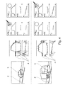
Fig. 1 : eine schematische Darstellung einer Anordnung des Radargeräts neben der Fahrbahn, -
Fig. 2 : Spektrogramme mehrerer in einem Messzeitraum angemessener Fahrzeuge, -
Fig. 3a : die prinzipielle Herleitung der Frequenzspektren der Signalkomponenten aus den Messsignalen eines Punktreflektors, -
Fig. 3b : die prinzipielle Herleitung der Frequenzspektren der Signalkomponenten aus den Messsignalen eines überwiegend frontal erfassten Fahrzeugs, -
Fig. 3c : die prinzipielle Herleitung der Frequenzspektren der Signalkomponenten aus den Messsignalen eines überwiegend seitlich erfassten Fahrzeugs, -
Fig. 4 : ein Beispiel einer Klassifizierung eines PKW und eines LKW anhand von klassifizierten Vergleichsmodellen.
-
Fig. 1 : a schematic representation of an arrangement of the radar next to the roadway, -
Fig. 2 : Spectrograms of Several Vehicles Reasonable in a Measurement Period, -
Fig. 3a : the principle derivation of the frequency spectra of the signal components from the measurement signals of a point reflector, -
Fig. 3b : the principle derivation of the frequency spectra of the signal components from the measurement signals of a predominantly frontally detected vehicle, -
Fig. 3c : the principle derivation of the frequency spectra of the signal components from the measurement signals of a predominantly laterally detected vehicle, -
Fig. 4 : an example of a classification of a car and a truck based on classified comparison models.
Für das Verfahren zum Klassifizieren eines oder auch zum gleichzeitigen Klassifizieren mehrerer sich auf einer Fahrbahn 2 fortbewegender Fahrzeuge 3 wird als ein winkelauflösendes Radargerät 1, ein FSK-Radargerät, eine Sonderform des aus dem Stand der Technik bekannten FMCW-Radars, verwendet. Mit dem FSK-Radargerät 1 können gleichzeitig mehrere Fahrzeuge 3 erfasst und auch verfolgt (Tracking) werden. Ein FSK-Radar 1 (FSK = Frequency Shift Keying) sendet eine Radarstrahlung 11 auf mindestens zwei alternierenden Trägerfrequenzen aus bzw. nimmt von erfassten Fahrzeugen 3 verursachte Reflexionen der mindestens zwei alternierenden Trägerfrequenzen wieder auf. Durch die Auswertung von Frequenzverschiebungen zwischen und innerhalb der beiden von den Fahrzeugen 3 reflektierten Trägerfrequenzen, wird innerhalb kurzer Zeit eine räumliche Auflösung zwischen mehreren Fahrzeugen 3 entsprechend deren Radialentfernungen RE, Radialgeschwindigkeiten und Objektwinkeln γ gegenüber dem Radargerät 1 ermöglicht.For the method of classifying one or even simultaneously classifying a plurality of
Verschiedene Verfahren und dazu geeignete Vorrichtungen zum Ableiten der genannten Parameter aus den Radarsignalen sind aus dem Stand der Technik bekannt, wie z. B. die in der
In Abhängigkeit von den Abstrahleigenschaften des Radargeräts 1 bildet die Radarstrahlung 11, wie in
Die vom Radargerät 1 ausgesendete Radarstrahlung 11 wird an den mit Radarstrahlung 11 beaufschlagten und die Radarstrahlung 11 reflektierenden Oberflächen der Fahrzeuge 3 reflektiert und die reflektierte Radarstrahlung 11 wieder vom Radargerät 1 erfasst. Anhand der ausgesendeten und reflektierten Radarstrahlung 11 werden die Fahrzeuge 3 angemessen. Durch eine Relativbewegung der den Radarkegel 12 durchfahrenden Fahrzeuge 3 gegenüber dem Radargerät 1 erzeugen diese in der reflektierten Radarstrahlung 11 Dopplerverschiebungen aus denen das Radargerät 1 niederfrequente Messsignale 4 generiert die den Dopplerverschiebungen entsprechen und in Form von Dopplerfrequenzen fD erfasst und ausgewertet werden. Die Auswertung der Messsignale 4 mittels des erfindungsgemäßen Verfahrens ermöglicht eine Klassifizierung der Fahrzeuge 3.The
Zur Durchführung des Verfahrens wird in einem ersten Verfahrensschritt das Radargerät 1 so zur Fahrbahn 2 angeordnet, dass eine Radialgeschwindigkeit, eine Radialentfernung RE und ein Objektwinkel γ von sich auf das Radargerät 1 zu bewegenden Fahrzeugen 3 aufgenommen werden kann. Das Radargerät 1 wird dazu neben der Fahrbahn 2 angeordnet, sodass die Symmetrieachse 13 mit einem Fahrbahnrand 21 einen horizontalen spitzen Aufstellwinkel α einschließt. Weiterhin ist das Radargerät 1 in Bodennähe (z. B. in üblicher Höhe der Radachsen der Fahrzeuge 3), in einer bekannten vertikalen Aufstellhöhe vAH und mit einem vertikalen Aufstellwinkel (nicht dargestellt) der Symmetrieachse 13 zur Oberfläche der Fahrbahn 2, von üblicherweise 0° aufgestellt, sodass die Symmetrieachse 13 parallel zur Oberfläche der Fahrbahn 2 ausgerichtet ist.For carrying out the method, in a first method step, the radar device 1 is arranged to the
In einer Ausführung des Verfahrens ist es auch möglich das Radargerät 1 direkt über der Fahrbahn 2, z. B. in Höhe einer die Fahrbahn 2 überspannenden Brücke anzubringen. In diesem Fall ist die Symmetrieachse 13 parallel zum Fahrbahnrand 21 und mit einem vertikalen Aufstellwinkel zur Oberfläche der Fahrbahn 2 orientiert. Die Fahrzeuge 3 werden somit an dem weit vom Radargerät 1 entfernten Ort, nahezu frontal bis zum nahe am Radargerät 1 liegenden Ort, nahezu von oben erfasst.In one embodiment of the method, it is also possible the radar device 1 directly above the
Die vom Radargerät 1 erfassten Messsignale 4 werden in Form der Dopplerfrequenzen fD ausgegeben. Aus den Dopplerfrequenzen fD werden direkt die Radialgeschwindigkeiten der angemessenen Fahrzeuge 3 ermittelt.The measured signals 4 detected by the radar device 1 are output in the form of the Doppler frequencies f D. The radial velocities of the
Zur vereinfachten Begriffsklärung wird das Fahrzeug 3, wie in
Die Radialentfernung RE des Fahrzeugs 3 entspricht damit dem direkten Abstand des Punktreflektors 33 zur punktförmigen Quelle. Sie wird unmittelbar aus einer Frequenzverschiebungsmessung zwischen den beiden Trägerfrequenzen des FSK-Radars 1 abgeleitet.The radial distance RE of the
Die Radialgeschwindigkeit des Fahrzeugs 3 ist damit die Geschwindigkeit, mit der sich der Punktreflektor 33 in radialer Richtung auf die punktförmige Quelle zu bewegt. Die Radialgeschwindigkeit ist nur eine Geschwindigkeitskomponente einer realen Fahrzeuggeschwindigkeit, mit der sich das Fahrzeug 3 in einer Fahrtrichtung 34 auf der Fahrbahn 2 bewegt. Aufgrund des seitlich neben der Fahrbahn 2 aufgestellten Radargeräts 1 ist die Fahrtrichtung 34 des Fahrzeug 3 am Radargerät 1 vorbei gerichtet. Bei einer vektoriellen Betrachtung lässt sich die Fahrzeuggeschwindigkeit aus einer Addition einer radial zum Radargerät 1 ausgerichteten Geschwindigkeitskomponente (Radialgeschwindigkeit) und einer rechtwinklig dazu ausgerichteten Geschwindigkeitskomponente (Bahngeschwindigkeit) ermitteln. Die Radialgeschwindigkeit wird unmittelbar aus der Dopplerfrequenz fD der vom Punktreflektor 33 reflektierten Radarstrahlung 1 1 abgeleitet.The radial velocity of the
Als Objektwinkel γ wird der Winkel bezeichnet, der an der punktförmigen Quelle der Radarstrahlung 11 zwischen der Symmetrieachse 13 und einer Geraden zum Punktreflektor 33 aufgespannt wird. Die Ermittlung des Objektwinkels γ erfolgt anhand zweier unterschiedlicher Phasenverschiebungen, der von der einen Senderfläche abgestrahlten Radarstrahlung 11, die an den beiden Empfängerflächen gemessen werden, nach dem Prinzip der Triangulationsrechnung.The object angle γ is the angle which is defined at the point source of the
Im Gegensatz zum idealen Punktreflektor 33 weist ein Fahrzeug 3 eine räumliche Ausdehnung mit einer Vielzahl räumlich verteilter und die Radarstrahlung 11 reflektierender Oberflächen auf, die wiederum eine Vielzahl von erfassbaren Punktreflektoren 33 bilden. Dementsprechend weist das für ein erfasstes Fahrzeug 3 aufgenommene Messsignal 4 auch eine Vielzahl von Dopplerfrequenzen fD auf. Je nach Radialentfernung RE, Objektwinkel γ und Fahrzeugwinkel ε des Fahrzeugs 3 werden an den Fahrzeugen 3 auch mehrere räumlich verteilte Reflexionen der Radarstrahlen 11 erfasst. Die Anzahl und Verteilung der Reflexionen an den Fahrzeugen 3 nimmt mit einer sich verringernden Radialentfernung RE zu, da aus der Perspektive des Radargeräts 1 auch die Größen der reflektierenden Oberflächen der Fahrzeuge 3 zunimmt. Für jede einzelne der erfassten Reflexionen kann die Radialentfernung RE, Radialgeschwindigkeit und der Objektwinkel γ, differenziert nach deren räumlichen Anordnung an den Oberflächen des Fahrzeugs 3 abgeleitet werden.In contrast to the
In einem zweiten Verfahrensschritt wird die den Radarkegel 12 bildende Radarstrahlung 11 vom Radargerät 1 ausgesendet. Bei der Durchfahrt von wenigstens einem Fahrzeug 3 durch den Radarkegel 12 wird die Radarstrahlung 11 teilweise an den reflektierenden Oberflächen des Fahrzeugs 3 reflektiert und die Reflexionen vom Radargerät 1 als Messsignale 4 mit einer entsprechenden Signalamplitude SA erfasst. Die Erfassung der Messsignale 4 erfolgt in einer Messzeit t zu mehreren Messzeitpunkten.In a second method step, the
Um einen ausreichenden Signal-Rausch-Abstand zu einem prinzipbedingt miterfassten Grundrauschen der Messsignale 4 herzustellen und die Eindeutigkeit bei der Erfassung der Messsignale 4 zu erhöhen, wird für die Signalamplituden SA sinnvollerweise ein Schwellwert festgelegt, den die Signalamplituden SA der erfassten Messsignale 4 überschreiten müssen, um bei einer nachfolgenden Signalverarbeitung berücksichtigt zu werden.In order to produce a sufficient signal-to-noise ratio to an inherent ground noise detected by the measurement signals 4 and to increase the uniqueness in the detection of the measurement signals 4, a threshold value is set for the signal amplitudes SA, the signal amplitudes SA of must exceed detected
In einem dritten Verfahrensschritt werden die Messsignale 4 in Form der Dopplerfrequenzen fD den Messzeitpunkten zugeordnet zwischengespeichert. Sie lassen sich über die Messzeit t auf einer Zeitachse aufgetragen. Alle erfassten Messsignale 4 eines angemessenen Fahrzeugs 3 lassen sich hierbei jeweils in Form eines zeitlichen Verlaufs der Dopplerfrequenzen fD als Spektrogramm darstellen.In a third method step, the measurement signals 4 are temporarily stored in the form of the Doppler frequencies f D associated with the measurement instants. They can be plotted on a time axis over the measuring time t. All detected
In
Anhand des zum spätesten Messzeitpunkt erfassten Fahrzeugs 3 (rechtes Spektrogramm in
Die Erfassung von Messsignalen 4 beginnt, wenn das Fahrzeug 3 in den Radarkegel 12 eintritt. Der Eintritt erfolgt an dem vom Radargerät 1 entfernten Ort, sodass das Fahrzeug 3 nahezu frontal von der Radarstrahlung 11 erfasst wird. Die Radarstrahlung 11 wird deshalb im Wesentlichen an den Oberflächen einer Fahrzeugfront 31 reflektiert, die aus der Perspektive des Radargeräts 1 noch sehr klein ist. Die von dieser reflektierten Radarstrahlung 11 erfassten Dopplerfrequenzen fD weisen daher eine geringe, noch undifferenzierte Spektralverteilung auf und die Messsignale ähneln damit den Messsignalen 4 des idealen Punktreflektors 33. Die Darstellung der Messsignale 4 im Spektrogramm zeigt deshalb bei frühen Messzeitpunkten, einen Anfangsbereich AB mit sehr geringer Spektralverteilung. Da an dem vom Radargerät 1 entfernten Ort die Bahngeschwindigkeit noch sehr gering ist, entspricht die Radialgeschwindigkeit in etwa der Fahrzeuggeschwindigkeit. Unter der Vorraussetzung, dass sich das Fahrzeug 3 während der Durchquerung des Radarkegels 12 mit konstanter Fahrzeuggeschwindigkeit entlang der Fahrbahn 2 bewegt, bleiben die Messsignale 4 im Spektrogramm ohne eine signifikante Änderung der Dopplerfrequenzen fD nahezu konstant.The detection of
Da die Fahrtrichtung 34 des Fahrzeugs 3 am Radargerät 1 vorbei gerichtet ist, nimmt mit abnehmender Radialentfernung RE des Fahrzeugs 3 zum Radargerät 1 die Radialgeschwindigkeit, durch die zunehmende Bahngeschwindigkeit, ebenfalls ab. In einem Mittenbereich MB weist der Verlauf der Messsignale 4 deshalb zunächst eine leichte Krümmung in Richtung kleinerer Dopplerfrequenzen fD mit einem kontinuierlich zunehmenden Abfall auf. Mit abnehmender Radialentfernung RE vergrößert sich, aus der Perspektive des Radargeräts 1, auch die reflektierende Oberfläche des Fahrzeugs 3. Weiterhin nimmt das Fahrzeug 3 bei abnehmender Radialentfernung RE einen anderen Objektwinkel γ zur Symmetrieachse 13 ein, sodass neben der Fahrzeugfront 31 auch zunehmend Oberflächen einer Fahrzeugflanke 32 zur Reflexion von Radarstrahlen 11 und damit zur Erzeugung von Dopplerfrequenzen fD beitragen. Das Radargerät 1 kann somit eine größere Anzahl von Reflexionen mit einer größeren räumlichen Streuung auf den Oberflächen des Fahrzeugs 3 erfassen als zu früheren Messzeitpunkten. Die Dopplerfrequenzen fD, die an den unterschiedlichen Oberflächen des räumlich ausgedehnten Fahrzeugs 3 erzeugt werden, weisen je nach deren Radialentfernung RE zum Radargerät 1 unterschiedliche Radialgeschwindigkeiten auf. Diese sehr geringen aber mit dem FSK-Radargerät 1 auflösbaren Unterschiede der Radialgeschwindigkeiten bzw. der gemessenen Dopplerfrequenzen fD äußern sich im Spektrogramm in einer, mit Verringerung der Radialentfernung RE zum Radargerät 1 kontinuierlich zunehmenden Verbreiterung der Spektralverteilung der Dopplerfrequenzen fD. Zum Ende der Durchfahrt durch den Radarkegel 12 befindet sich das Fahrzeug 3 nahe am Radargerät 1. Der Objektwinkel γ ist dadurch entsprechend groß, sodass am Fahrzeug 3 zum größten Teil die Oberflächen der Fahrzeugflanke 32 von der Radarstrahlung 11 erfasst werden. Aufgrund der Länge des Fahrzeugs 3 wird in dieser Position eine maximale räumliche Streuung der von der Fahrzeugfront 31 und Fahrzeugflanke 32 ausgehenden Reflexionen erreicht. Durch die stark differenzierte räumliche Streuung werden auch die Unterschiede der Radialgeschwindigkeiten bzw. der gemessenen Dopplerfrequenzen fD maximal. Im Spektogramm zeigen die Messsignale 4 deshalb am Ende des Mittenbereichs MB, kurz vor Austritt des Fahrzeugs 3 aus dem Radarkegel 12 eine maximal mögliche Spektralverteilung.Since the direction of
Zur Darstellung der zunehmenden Spektralverteilung werden in
Kurz vor dem Austritt aus dem Radarkegel 12 bewegt sich das Fahrzeug 3 auf der Fahrbahn 2 am Radargerät 1 vorbei, sodass die Bahngeschwindigkeit sehr stark zunimmt und die Radialgeschwindigkeit sehr stark abnimmt. Der Abfall der Radialgeschwindigkeit ist zu diesem Messzeitpunkt maximal. Sobald das Fahrzeug 3 den Radarkegel 12 verlässt, können keine Reflexionen mehr erfasst werden. Das Messsignal 4 weist deshalb einen Endbereich EB auf, in dem die Aufzeichnungen der unterschiedlichen Dopplerfrequenzen fD1 bis fD5 enden. Durch die Längenausdehnung des Fahrzeugs 3 treten die über die Länge des Fahrzeugs 3 verteilten reflektierenden Oberflächen zeitlich nacheinander aus dem Radarkegel 12 aus, sodass es im Endbereich EB zu einer starken zeitlichen Auffächerung der Messsignale 4 kommt. Die zeitliche Ausdehnung der Auffächerung ist proportional zur Länge des Fahrzeugs 3.Shortly before exiting the
In einem vierten Verfahrensschritt wird in dem Spektrogramm ein Bewertungsbereich BB der Messsignale 4 ermittelt, in dem die Spektralverteilung der Dopplerfrequenzen fD eine maximale Bandbreite aufweist. Wie anhand von
Die detaillierte Auswertung kann prinzipiell auch zu früheren Messzeitpunkten, außerhalb des Bewertungsbereichs BB erfolgen. Aufgrund der höheren spektralen Dichte nimmt dort jedoch die Eindeutigkeit der Signalkomponenten und damit die Zuverlässigkeit der Auswertung ab. Zu späteren Messzeitpunkten, außerhalb des Bewertungsbereichs BB, ist die detaillierte Auswertung nicht mehr möglich, da hier das Fahrzeug 3 bereits den Radarkegel 12 verlässt und so nicht mehr alle Dopplerfrequenzen fD zur Auswertung zur Verfügung stehen.In principle, the detailed evaluation can also take place at earlier measuring times, outside the evaluation area BB. Due to the higher spectral density, however, the uniqueness of the signal components and thus the reliability of the evaluation decreases there. At later measuring times, outside of the evaluation area BB, the detailed evaluation is no longer possible since here the
Die detaillierte Auswertung der Signalkomponenten soll anhand der in den
Zum besseren Verständnis wird in
In den
In
Das Frequenzspektrum der Signalamplituden SA, das heißt, die Funktion der Signalamplituden SA über Dopplerfrequenz fD, zeigt zwei charakteristische Abschnitte. In dem Abschnitt der niedrigeren Dopplerfrequenzen fD ist der Frequenzverlauf durch einen nahezu linearen Anstieg der Signalamplituden SA gekennzeichnet. Dieser Anstieg kann den an der Fahrzeugfront 31 erzeugten Reflexionen zugeordnet werden, da die an der Fahrzeugfront 31 gemessenen Radialgeschwindigkeiten im Gegensatz zu den an der Fahrzeugflanke 32 gemessenen, aufgrund des größeren Anteils der Bahngeschwindigkeit, geringer sind. Die maximalen Signalamplituden SA werden an der zum Radargerät 1 weisenden Ecke des Fahrzeugs 3 und deren Übergängen zur Fahrzeugfront 31 und Fahrzeugflanke 32 erreicht. Hier ist der Anteil der rechtwinklig zu der gedachten radialen Verbindung zum Radargerät 1 ausgerichteten Oberflächen besonders hoch, sodass die Radarstrahlung 11 besonders gut reflektiert wird. Vom Maximum aus fallen die Signalamplituden SA zu den höheren Dopplerfrequenzen fD hin wieder ab. Der Abfall der Signalamplitude SA wird durch die (im Gegensatz zur Fahrzeugecke) weniger direkt auf das Radar zeigenden Reflektoren erzeugt. Die höhere Radialgeschwindigkeit dagegen führt zu der bereits angesprochenen höheren spektralen Bandbreite.The frequency spectrum of the signal amplitudes SA, that is, the function of the signal amplitudes SA over Doppler frequency f D , shows two characteristic sections. In the section of the lower Doppler frequencies f D the frequency characteristic is characterized by a nearly linear increase of the signal amplitudes SA. This increase can be attributed to the reflections generated at the
Das Frequenzspektrum der Radialentfernung RE, das heißt die Funktion der Radialentfernung RE über die Dopplerfrequenz fD, zeigt ebenfalls wieder zwei charakteristische Abschnitte. Im Abschnitt niedrigerer Dopplerfrequenzen fD ist die Radialentfernung RE nahezu unverändert. Dieser Abschnitt wird durch die an der Fahrzeugfront 31 erzeugten Reflexionen gebildet. Da die Fahrzeugfront 31 nahezu orthogonal zu der gedachten radialen Verbindung zum Radargerät 1 orientiert ist, treten an der Fahrzeugfront 31 keine wesentlichen Unterschiede in der Radialentfernung RE auf. Beim Übergang von der Fahrzeugfront 31 auf die Fahrzeugflanke 32 nehmen die Radialentfernungen RE entsprechend der Länge und den damit verbundenen Objektwinkeländerungen zur Symmetrieachse 13 des angemessenen Fahrzeugs 3 zu. Im Abschnitt der höheren Dopplerfrequenzen fD weist die Funktion daher einen Anstieg auf. Das Frequenzspektrum ist im Abschnitt des Anstiegs der Radialentfernung RE schmaler, weil durch den schrägen Winkel die Änderung der Radialgeschwindigkeit geringer ist. Die Signalstärke (reflektierte Radarstrahlung) hat keinen Einfluss auf die Breite sondern nur auf die Höhe.The frequency spectrum of the radial distance RE, that is, the function of the radial distance RE on the Doppler frequency f D , also shows again two characteristic sections. In the portion of lower Doppler frequencies f D , the radial distance RE is almost unchanged. This section is formed by the reflections generated at the
Das Frequenzspektrum der Objektwinkel γ, das heißt, die Funktion der Objektwinkel γ über die Dopplerfrequenz fD, ist durch einen linear abfallenden Objektwinkel γ gekennzeichnet. Der Abfall ist dabei ein Ausdruck für die Länge und Breite des Fahrzeugs 3, die aus der Perspektive des Radargeräts 1 durch den Fahrzeugwinkel ε vom Radargerät 1 erfasst wird.The frequency spectrum of the object angle γ, that is, the function of the object angle γ over the Doppler frequency f D , is characterized by a linearly sloping object angle γ. The waste is an expression of the length and width of the
In
Entsprechen der von der Fahrzeugfront 31 und der Fahrzeugflanke 32 stammenden Anteile der zur Reflexion der Radarstrahlung 11 beitragenden reflektierenden Oberflächen ändern sich auch die Aufteilung der charakteristischen Abschnitte in den Frequenzspektren der Signalamplitude SA und der Radialentfernung RE. Bei einem ähnlichen Signalverlauf ist nun der Anteil des an der Fahrzeugfront 31 aufgenommenen Frequenzspektrums deutlich schmaler als der an der Fahrzeugflanke 32 aufgenommene Anteil.If the proportions of the reflecting surfaces contributing to the reflection of the
Im Frequenzspektrum der Objektwinkel γ zeigt der Frequenzverlauf einen deutlich steileren Anstieg des Objektwinkels γ.In the frequency spectrum of the object angle γ, the frequency curve shows a significantly steeper increase of the object angle γ.
Wie der Vergleich der Frequenzspektren bei unterschiedlichen Fahrzeugwinkeln ε zeigt, ist der Verlauf der ausgewerteten Signalkomponente typisch für eine bestimmte Ausrichtung und Länge des Fahrzeugs 3.As the comparison of the frequency spectra at different vehicle angles ε shows, the course of the evaluated signal component is typical for a specific orientation and length of the
Die Klassifizierung des angemessenen Fahrzeugs 3 erfolgt in einem fünften Verfahrensschritt. Dazu werden die für das Fahrzeug 3 ermittelten Frequenzspektren mit zuvor anhand von Modelfahrzeugen, das heißt Fahrzeugen deren Klassifikationszuordnung bekannt ist, ermittelten und abgespeicherten Frequenzspektren verglichen, die in Form von Vergleichsmodellen VM vorliegen. Damit ein direkter Vergleich möglich ist, wurden die Vergleichsmodelle VM zuvor mit einem Radargerät 1 angelernt, welches genauso zur Fahrbahn 2 angeordnet war, wie das Radargerät 1 jetzt zur Verfahrensdurchführung aufgestellt wurde und die Frequenzspektren wurden aus den Messsignalen zu einem Messzeitpunkt abgeleitet, bei welchem sich das Vergleichsmodell VM in einer gleichen Radialentfernung RE befand. Die Vergleichsmodelle VM besitzen daher bereits eine Zuordnung zu einer Fahrzeugklasse. Wenn eine Übereinstimmung des angemessenen Fahrzeugs 3 mit einem der Vergleichsmodelle VM festgestellt wird, kann das angemessene Fahrzeug 3 der entsprechenden Fahrzeugklasse zugewiesen werden. Das angemessene Fahrzeug 3 ist somit ebenfalls klassifiziert.The classification of the
In
Die Vergleichsmodelle VM werden bevorzugt während des Verfahrens mit Hilfe aus einer für die unterschiedlichen Fahrzeugklassen jeweils vorgegebenen Formel und den aktuellen Parametern, die aus der Aufstellung des Radargerätes 1 und den Messsignalen 4 gewonnen werden, nämlich die Radialgeschwindigkeiten, Radialentfernungen RE, der Fahrzeugwinkel ε und die Objektwinkel γ, berechnet.The comparison models VM are preferred during the process with the help of a formula for the different vehicle classes and the current parameters, which are obtained from the installation of the radar device 1 and the measurement signals 4, namely the radial velocities, radial distances RE, the vehicle angle ε and the Object angle γ, calculated.
Die Vergleichsmodelle VM können auch bei einer festen Anordnung des Radargeräts 1 zur Fahrbahn 2, aus zuvor aufgenommenen Verläufen der Messsignale 4 erzeugt werden. Dazu wird in den zuvor aufgenommenen Verläufen der Messsignale 4 zunächst die Länge der Fahrzeuge 3 ermittelt. Die Länge der Fahrzeuge 3 wird am Ende des Mittenbereichs MB des Verlaufes der Messsignale 4 aus der Bandbreite der Spektralverteilung des Verlaufes der Messsignale 4 (z. B. zum Bewertungszeitpunkt tB) ermittelt, wobei große Fahrzeuge 3 eine große Bandbreite und kurze Fahrzeuge 3 eine kleine Bandbreite aufweisen.The comparison models VM can also be generated with a fixed arrangement of the radar device 1 to the
Es ist auch möglich, die Länge der Fahrzeuge 3 in Abhängigkeit von der Radialgeschwindigkeit aus der Zeitdauer zu ermitteln, die das Fahrzeug 3 benötigt um sich aus dem Radarkegel 12 heraus zu bewegen. Die Zeitdauer kann am Ende des Verlaufes der Messsignale 4 aus der Breite des Endbereichs EB ermittelt werden.It is also possible to determine the length of the
Entsprechend der ermittelten Länge der Fahrzeuge 3 erfolgt mittels einer Wahrscheinlichkeitsbetrachtung eine Einordnung der zuvor aufgenommenen oder zeitgleich ermittelten Verläufe der Messsignale 4 in unterschiedliche Gruppen. Durch eine (manuelle) Bewertung der in den Gruppen eingeordneten Fahrzeuge 3 werden die Gruppen und damit die darin eingeordneten Verläufe der Messsignale 4 bzw. Fahrzeuge 3 einer entsprechenden Fahrzeugklasse zugeordnet.In accordance with the determined length of the
Zur Erzeugung der Vergleichsmodelle VM werden alle in eine Gruppe eingeordneten, klassifizierten Verläufe von Messsignalen 4 über deren gesamten zeitlichen Verlauf gewichtet und akkumuliert. Im akkumulierten Verlauf der Messsignale 4 wird der Abschnitt der größten spektralen Bandbreite ermittelt und dort zu einem Bewertungszeitpunkt tB die ableitbaren Signalkomponenten (Signalamplitude SA, Radialentfernung RE, Objektwinkel γ) ermittelt. Die aus den Signalkomponenten erzeugten einzelnen Frequenzspektren beinhalten nunmehr ein der Fahrzeugklasse entsprechendes durchschnittliches Frequenzspektrum und können als Vergleichsmodelle VM verwendet werden. Für die Vergleichsmodelle VM ist es dabei ausreichend nur charakteristische Abschnitte, z. B. Anstiege oder Knickstellen der Frequenzspektren zu verwenden und die verbleibenden Abschnitte, wie in
Vergleichsmodelle VM können auch aus einer theoretischen Berechnung heraus gewonnen werden. Dazu werden die Aufstellbedingungen (horizontaler Aufstellabstand hAA, horizontaler Aufstellwinkel α, vertikale Aufstellhöhe vAH und vertikaler Aufstellwinkel β) des Radargeräts 1 an einem realen Einsatzort als Messsignale 4 erfasst. Zur Darstellung der Fahrzeuge 3 werden vereinfachte, maßstabsgetreue Fahrzeugmodelle (z. B. die Oberflächen einer Quaderform) generiert. Entsprechend der Aufstellbedingungen und der Fahrzeugmodelle können theoretische Reflexionsantworten berechnet werden, aus denen die Vergleichsmodelle VM erstellt werden können.Comparison models VM can also be obtained from a theoretical calculation. For this purpose, the installation conditions (horizontal installation distance hAA, horizontal installation angle α, vertical installation height vAH and vertical installation angle β) of the radar device 1 at a real location of use are detected as measurement signals 4. To represent the
Prinzipiell ist das Verfahren auch dann anwendbar, wenn die Aufstellbedingungen des Radargeräts 1 gegenüber der Fahrbahn 2 nicht genau bekannt sind, da im Verfahren ausschließlich die auf das Radargerät 1 bezogenen Messsignale 4 (Dopplerfrequenz fD, Radialentfernung RE und Objektwinkel y) zur Klassifizierung der Fahrzeuge 3 verwendet werden. Der Radarkegel 12 kann deshalb mit einem gewissen Toleranzbereich zur Fahrbahn 2 ausgerichtet werden, in dem die benötigten Messsignale 4 noch mit ausreichender Sicherheit erfasst werden können. Bei einer Anordnung des Radargeräts 1, die nicht den Aufstellbedingungen entspricht, bei denen die Vergleichsmodelle VM erstellt wurden, ist es jedoch immer erforderlich vor Anwendung des Verfahrens neue Vergleichsmodelle VM zu erstellen, die den aktuellen Aufstellbedingungen entsprechen.In principle, the method is also applicable if the installation conditions of the radar device 1 with respect to the
Eine Anordnung des Radargeräts 1 ohne Kenntnis der Aufstellbedingungen hat außerdem den Nachteil, dass die Fahrzeuggeschwindigkeit nicht ermittelt werden kann. Damit entfällt beispielsweise die Möglichkeit, Geschwindigkeitsverstöße der Fahrzeuge 3 zu erkennen und diese in Abhängigkeit der Klassifikation der Fahrzeuge 3 auszuwerten. Grundsätzlich können die Aufstellbedingung aber auch vom Radargerät 1 automatisch gelernt werden, so dass es dann auch für die Fahrzeuggeschwindigkeit wieder messfähig ist.An arrangement of the radar device 1 without knowledge of the setup conditions also has the disadvantage that the vehicle speed can not be determined. This eliminates, for example, the possibility of detecting speed violations of the
- 11
- Radargerätradar
- 1111
- Radarstrahlungradar radiation
- 1212
- Radarkegelemission cone
- 1313
- Symmetrieachseaxis of symmetry
- 22
- Fahrbahnroadway
- 33
- Fahrzeugvehicle
- 3131
- Fahrzeugfrontvehicle front
- 3232
- Fahrzeugflankevehicle edge
- 3333
- Punktreflektorpoint reflector
- 3434
- Fahrtrichtungdirection of travel
- 44
- Messsignalmeasuring signal
- BBBB
- Bewertungsbereichreview area
- ABFROM
- Anfangsbereichinitial region
- MBMB
- Mittenbereichmid-range
- EBEB
- Endbereichend
- tt
- Messzeitmeasuring time
- tB t B
- BewertungszeitpunktValuation Point
- SASA
- Signalamplitudesignal amplitude
- RERE
- Radialentfernungradial Distance
- hAAHaa
- horizontaler Aufstellabstandhorizontal installation distance
- vAHvah
- vertikale Aufstellhöhevertical installation height
- fD f D
- DopplerfrequenzDoppler frequency
- VMVM
- Vergleichsmodellcomparison model
- αα
- horizontaler Aufstellwinkelhorizontal installation angle
- γγ
- Objektwinkelobject angle
- εε
- Fahrzeugwinkelvehicle angle
Claims (5)
Priority Applications (1)
| Application Number | Priority Date | Filing Date | Title |
|---|---|---|---|
| PL13179175T PL2698648T3 (en) | 2012-08-14 | 2013-08-02 | Method for classifying vehicles in motion |
Applications Claiming Priority (1)
| Application Number | Priority Date | Filing Date | Title |
|---|---|---|---|
| DE102012107445.3A DE102012107445B8 (en) | 2012-08-14 | 2012-08-14 | Method for classifying moving vehicles |
Publications (2)
| Publication Number | Publication Date |
|---|---|
| EP2698648A1 true EP2698648A1 (en) | 2014-02-19 |
| EP2698648B1 EP2698648B1 (en) | 2019-10-30 |
Family
ID=48948261
Family Applications (1)
| Application Number | Title | Priority Date | Filing Date |
|---|---|---|---|
| EP13179175.8A Active EP2698648B1 (en) | 2012-08-14 | 2013-08-02 | Method for classifying vehicles in motion |
Country Status (9)
| Country | Link |
|---|---|
| US (1) | US9341707B2 (en) |
| EP (1) | EP2698648B1 (en) |
| CN (1) | CN103593980B (en) |
| AU (1) | AU2013216598B2 (en) |
| DE (1) | DE102012107445B8 (en) |
| ES (1) | ES2764775T3 (en) |
| LT (1) | LT2698648T (en) |
| PL (1) | PL2698648T3 (en) |
| RU (1) | RU2608590C2 (en) |
Families Citing this family (28)
| Publication number | Priority date | Publication date | Assignee | Title |
|---|---|---|---|---|
| DE102013104443B4 (en) | 2013-04-30 | 2022-03-17 | Jenoptik Robot Gmbh | Traffic monitoring system for measuring the speed and allocation of moving vehicles in a multi-target recording module |
| DE102014003152A1 (en) | 2014-03-03 | 2015-09-03 | Jenoptik Robot Gmbh | Method and device for determining at least one object parameter of a means of transport |
| US20170307733A1 (en) * | 2014-07-03 | 2017-10-26 | GM Global Technology Operations LLC | Vehicle radar methods and systems |
| US9733350B2 (en) * | 2014-07-03 | 2017-08-15 | GM Global Technology Operations LLC | Vehicle radar control |
| US9664779B2 (en) * | 2014-07-03 | 2017-05-30 | GM Global Technology Operations LLC | Object classification for vehicle radar systems |
| WO2016194036A1 (en) * | 2015-05-29 | 2016-12-08 | 三菱電機株式会社 | Radar signal processing device |
| CN105629235B (en) * | 2015-12-29 | 2019-03-15 | 大连楼兰科技股份有限公司 | The signal processing apparatus of the combined waveform automobile lane change auxiliary system of multi-target detection |
| CN105629211B (en) * | 2015-12-29 | 2019-03-15 | 大连楼兰科技股份有限公司 | The signal processing method and automobile lane change auxiliary system of the combined waveform automobile lane change auxiliary system of multi-target detection |
| CN105629234A (en) * | 2015-12-29 | 2016-06-01 | 大连楼兰科技股份有限公司 | Automobile lane-changing auxiliary system signal processing method |
| CN107134143A (en) * | 2016-02-26 | 2017-09-05 | 南京航空航天大学 | A kind of vehicle flowrate based on continuous wave radar sentences method for distinguishing with vehicle |
| US9984704B2 (en) * | 2016-08-05 | 2018-05-29 | Electronics And Telecommunications Research Institute | Vehicle classification system and method |
| WO2018047805A1 (en) * | 2016-09-09 | 2018-03-15 | 日本電気株式会社 | Device for estimating speed of moving sound source, speed monitoring system, method for estimating speed of moving sound source, and storage medium in which program for estimating speed of moving sound source is stored |
| KR101752858B1 (en) * | 2016-12-09 | 2017-07-19 | 메타빌드주식회사 | Radar-based high-precision unexpected incident detecting system |
| DE102017221120A1 (en) * | 2017-11-27 | 2019-05-29 | Zf Friedrichshafen Ag | Evaluation procedure for RADAR measurement data of a mobile RADAR measuring system |
| CN107993443B (en) * | 2017-12-25 | 2021-09-21 | 深圳市金溢科技股份有限公司 | ETC lane transaction method and system based on vehicle type classification |
| DE102018201303A1 (en) * | 2018-01-29 | 2019-08-01 | Robert Bosch Gmbh | Method and device for operating a plurality of sensors of a vehicle |
| DE102018104808A1 (en) | 2018-03-02 | 2019-09-05 | Jenoptik Robot Gmbh | Method and device for estimating the height of a reflector of a vehicle |
| EP3553552B1 (en) * | 2018-04-11 | 2022-05-25 | Aptiv Technologies Limited | Method for the recognition of a moving pedestrian |
| CN109615903B (en) * | 2018-11-12 | 2021-08-17 | 合肥晟泰克汽车电子股份有限公司 | Parking space identification method |
| DE102018222672A1 (en) * | 2018-12-20 | 2020-06-25 | Robert Bosch Gmbh | Determination of the orientation of objects with radar and other electromagnetic interrogation radiation |
| CN111727380A (en) * | 2018-12-26 | 2020-09-29 | 深圳市大疆创新科技有限公司 | Target detection method, system and computer readable storage medium |
| CN110007279B (en) * | 2019-04-04 | 2020-01-21 | 吉林大学 | Target visibility judgment method based on millimeter wave radar model |
| CN110796872B (en) * | 2019-11-13 | 2020-11-06 | 佛山科学技术学院 | A collection system for lane collection vehicle model |
| CN111047868B (en) * | 2020-01-17 | 2020-12-11 | 深圳市戴升智能科技有限公司 | Road vehicle flow detection method and device, computer equipment and storage medium |
| US11393332B2 (en) * | 2020-02-27 | 2022-07-19 | Pixart Imaging Inc. | Detection device and indoor navigation system |
| CN111815962A (en) * | 2020-07-08 | 2020-10-23 | 支付宝(杭州)信息技术有限公司 | Vehicle identity identification method and device, master device and slave device |
| WO2022256397A1 (en) * | 2021-06-03 | 2022-12-08 | Wavesense, Inc. | Vehicle identification using surface-penetrating radar |
| KR102475219B1 (en) * | 2022-09-21 | 2022-12-07 | 국방과학연구소 | Apparatus, method, computer-readable storage medium and computer program for classifying target of synthetic aperture radar based on data augment in the form of video |
Citations (4)
| Publication number | Priority date | Publication date | Assignee | Title |
|---|---|---|---|---|
| DE3810357A1 (en) | 1988-03-26 | 1989-10-05 | Licentia Gmbh | METHOD FOR LOCAL TRAFFIC DATA ACQUISITION AND EVALUATION AND DEVICE FOR CARRYING OUT THE METHOD |
| DE102004040015B4 (en) | 2004-08-16 | 2006-12-07 | S.M.S., Smart Microwave Sensors Gmbh | Method and device for detecting an electromagnetic signal emitted by a transmitting antenna |
| EP1990654A1 (en) | 2007-05-07 | 2008-11-12 | ROBOT Visual Systems GmbH | Method and device for determining the automobile class of automobiles |
| EP2011103B1 (en) | 2006-03-29 | 2011-03-16 | Nederlandse Organisatie voor toegepast -natuurwetenschappelijk onderzoek TNO | Sensor for a traffic response system and traffic control system using a sensor |
Family Cites Families (7)
| Publication number | Priority date | Publication date | Assignee | Title |
|---|---|---|---|---|
| DE59506752D1 (en) * | 1994-03-17 | 1999-10-14 | Siemens Ag | Method and device for classifying vehicles using a traffic radar device |
| JP2930236B1 (en) * | 1998-01-26 | 1999-08-03 | 本田技研工業株式会社 | Radar equipment |
| US7339517B2 (en) * | 2003-12-16 | 2008-03-04 | Murata Manufacturing Co., Ltd. | Radar |
| NL1027018C2 (en) * | 2004-09-10 | 2006-03-13 | Gatsometer Bv | Method and system for observing with radar the passing of a point to be monitored on a road through a vehicle. |
| CN101162507B (en) * | 2006-10-13 | 2010-05-12 | 同方威视技术股份有限公司 | Method for recognizing vehicle type of moving care |
| CN100520853C (en) * | 2007-10-12 | 2009-07-29 | 清华大学 | Vehicle type classification method based on single frequency continuous-wave radar |
| CN102360528B (en) * | 2011-07-01 | 2013-08-28 | 上海慧昌智能交通系统有限公司 | Method for recognizing vehicle type based on Doppler traffic radar |
-
2012
- 2012-08-14 DE DE102012107445.3A patent/DE102012107445B8/en active Active
-
2013
- 2013-07-18 US US13/945,035 patent/US9341707B2/en active Active
- 2013-08-02 EP EP13179175.8A patent/EP2698648B1/en active Active
- 2013-08-02 LT LTEP13179175.8T patent/LT2698648T/en unknown
- 2013-08-02 PL PL13179175T patent/PL2698648T3/en unknown
- 2013-08-02 ES ES13179175T patent/ES2764775T3/en active Active
- 2013-08-13 RU RU2013137825A patent/RU2608590C2/en active
- 2013-08-13 AU AU2013216598A patent/AU2013216598B2/en active Active
- 2013-08-14 CN CN201310354392.7A patent/CN103593980B/en active Active
Patent Citations (4)
| Publication number | Priority date | Publication date | Assignee | Title |
|---|---|---|---|---|
| DE3810357A1 (en) | 1988-03-26 | 1989-10-05 | Licentia Gmbh | METHOD FOR LOCAL TRAFFIC DATA ACQUISITION AND EVALUATION AND DEVICE FOR CARRYING OUT THE METHOD |
| DE102004040015B4 (en) | 2004-08-16 | 2006-12-07 | S.M.S., Smart Microwave Sensors Gmbh | Method and device for detecting an electromagnetic signal emitted by a transmitting antenna |
| EP2011103B1 (en) | 2006-03-29 | 2011-03-16 | Nederlandse Organisatie voor toegepast -natuurwetenschappelijk onderzoek TNO | Sensor for a traffic response system and traffic control system using a sensor |
| EP1990654A1 (en) | 2007-05-07 | 2008-11-12 | ROBOT Visual Systems GmbH | Method and device for determining the automobile class of automobiles |
Non-Patent Citations (1)
| Title |
|---|
| JIANXIN FANG ET AL: "A Low-cost Vehicle Detection and Classification System based on Unmodulated Continuous-wave Radar", INTELLIGENT TRANSPORTATION SYSTEMS CONFERENCE, 2007. ITSC 2007. IEEE, IEEE, PI, 30 September 2007 (2007-09-30), pages 715 - 720, XP031151484, ISBN: 978-1-4244-1395-9 * |
Also Published As
| Publication number | Publication date |
|---|---|
| AU2013216598A1 (en) | 2014-03-06 |
| CN103593980B (en) | 2017-05-17 |
| DE102012107445B4 (en) | 2016-03-03 |
| PL2698648T3 (en) | 2020-05-18 |
| DE102012107445A1 (en) | 2014-05-15 |
| US20140049420A1 (en) | 2014-02-20 |
| CN103593980A (en) | 2014-02-19 |
| AU2013216598B2 (en) | 2017-03-09 |
| EP2698648B1 (en) | 2019-10-30 |
| RU2013137825A (en) | 2015-02-20 |
| ES2764775T3 (en) | 2020-06-04 |
| RU2608590C2 (en) | 2017-01-23 |
| US9341707B2 (en) | 2016-05-17 |
| LT2698648T (en) | 2020-02-10 |
| DE102012107445B8 (en) | 2016-04-28 |
Similar Documents
| Publication | Publication Date | Title |
|---|---|---|
| EP2698648B1 (en) | Method for classifying vehicles in motion | |
| DE102012107444B3 (en) | Method for classifying traveling vehicles e.g. passenger car, by tracking vehicle position magnitude in flowing traffic, involves comparing discontinuity portion length with stored typical velocity-normalized lengths to classify vehicle | |
| EP2674776B1 (en) | Indicator to determine whether an object can be driven over | |
| EP1990654B1 (en) | Method and device for determining the automobile class of automobiles | |
| EP1797448B1 (en) | Object verification method in radar systems for motor vehicles | |
| EP3485290B1 (en) | Method and system for scanning an object | |
| EP2910968B1 (en) | Device and method for detecting a wheel axle of a vehicle | |
| DE112010005662T5 (en) | Object identification device and method | |
| EP2538239B1 (en) | Device and method for detecting wheels | |
| DE102010029699A1 (en) | Radar sensor and method for detecting precipitation with a radar sensor | |
| DE102010030289A1 (en) | Radar sensor and method for operating a radar sensor | |
| WO2012175470A1 (en) | Method and device for detecting a rotating wheel | |
| DE102013209736A1 (en) | Method for evaluating obstacles in a driver assistance system for motor vehicles | |
| EP2538238B1 (en) | Device and method for detecting wheels | |
| DE3940404A1 (en) | METHOD AND DEVICE FOR DOUBLE EFFECT SPEED MEASUREMENT | |
| DE19953790A1 (en) | Object detection system for cars has a multiple beam FMCW radar sensor mounted on the car which measures the distance and speed of reflecting objects | |
| EP1158311A2 (en) | Device and method for distance and velocity determination | |
| DE102018200688B4 (en) | Method and device for operating an acoustic sensor | |
| DE19754220B4 (en) | Method and device for detecting an impending or potential collision | |
| EP0403954B1 (en) | Clear track signalling device for railways | |
| DE102017220925A1 (en) | Method for operating a LIDAR sensor and LIDAR sensor | |
| EP0674184A1 (en) | Method and apparatus for the classification of vehicles by means of a traffic radar system | |
| DE4313352C2 (en) | Method and device for the automatic detection of moving people and / or vehicles according to the Doppler principle | |
| EP2287630B1 (en) | Optoelectronic recording device | |
| WO2023083875A1 (en) | Method, device and system for operating a rail vehicle for warning about a possible collision |
Legal Events
| Date | Code | Title | Description |
|---|---|---|---|
| AK | Designated contracting states |
Kind code of ref document: A1 Designated state(s): AL AT BE BG CH CY CZ DE DK EE ES FI FR GB GR HR HU IE IS IT LI LT LU LV MC MK MT NL NO PL PT RO RS SE SI SK SM TR |
|
| AX | Request for extension of the european patent |
Extension state: BA ME |
|
| PUAI | Public reference made under article 153(3) epc to a published international application that has entered the european phase |
Free format text: ORIGINAL CODE: 0009012 |
|
| 17P | Request for examination filed |
Effective date: 20140813 |
|
| RBV | Designated contracting states (corrected) |
Designated state(s): AL AT BE BG CH CY CZ DE DK EE ES FI FR GB GR HR HU IE IS IT LI LT LU LV MC MK MT NL NO PL PT RO RS SE SI SK SM TR |
|
| STAA | Information on the status of an ep patent application or granted ep patent |
Free format text: STATUS: EXAMINATION IS IN PROGRESS |
|
| 17Q | First examination report despatched |
Effective date: 20170217 |
|
| GRAP | Despatch of communication of intention to grant a patent |
Free format text: ORIGINAL CODE: EPIDOSNIGR1 |
|
| STAA | Information on the status of an ep patent application or granted ep patent |
Free format text: STATUS: GRANT OF PATENT IS INTENDED |
|
| INTG | Intention to grant announced |
Effective date: 20190604 |
|
| RIN1 | Information on inventor provided before grant (corrected) |
Inventor name: LEHNING, MICHAEL Inventor name: PROEFROCK, DIMA |
|
| GRAS | Grant fee paid |
Free format text: ORIGINAL CODE: EPIDOSNIGR3 |
|
| GRAA | (expected) grant |
Free format text: ORIGINAL CODE: 0009210 |
|
| STAA | Information on the status of an ep patent application or granted ep patent |
Free format text: STATUS: THE PATENT HAS BEEN GRANTED |
|
| AK | Designated contracting states |
Kind code of ref document: B1 Designated state(s): AL AT BE BG CH CY CZ DE DK EE ES FI FR GB GR HR HU IE IS IT LI LT LU LV MC MK MT NL NO PL PT RO RS SE SI SK SM TR |
|
| REG | Reference to a national code |
Ref country code: GB Ref legal event code: FG4D Free format text: NOT ENGLISH |
|
| RIN1 | Information on inventor provided before grant (corrected) |
Inventor name: PROEFROCK, DIMA Inventor name: LEHNING, MICHAEL |
|
| REG | Reference to a national code |
Ref country code: CH Ref legal event code: EP |
|
| REG | Reference to a national code |
Ref country code: DE Ref legal event code: R096 Ref document number: 502013013820 Country of ref document: DE |
|
| REG | Reference to a national code |
Ref country code: AT Ref legal event code: REF Ref document number: 1196743 Country of ref document: AT Kind code of ref document: T Effective date: 20191115 |
|
| REG | Reference to a national code |
Ref country code: IE Ref legal event code: FG4D Free format text: LANGUAGE OF EP DOCUMENT: GERMAN |
|
| REG | Reference to a national code |
Ref country code: SE Ref legal event code: TRGR |
|
| REG | Reference to a national code |
Ref country code: NL Ref legal event code: FP |
|
| PG25 | Lapsed in a contracting state [announced via postgrant information from national office to epo] |
Ref country code: NO Free format text: LAPSE BECAUSE OF FAILURE TO SUBMIT A TRANSLATION OF THE DESCRIPTION OR TO PAY THE FEE WITHIN THE PRESCRIBED TIME-LIMIT Effective date: 20200130 Ref country code: GR Free format text: LAPSE BECAUSE OF FAILURE TO SUBMIT A TRANSLATION OF THE DESCRIPTION OR TO PAY THE FEE WITHIN THE PRESCRIBED TIME-LIMIT Effective date: 20200131 Ref country code: PT Free format text: LAPSE BECAUSE OF FAILURE TO SUBMIT A TRANSLATION OF THE DESCRIPTION OR TO PAY THE FEE WITHIN THE PRESCRIBED TIME-LIMIT Effective date: 20200302 Ref country code: FI Free format text: LAPSE BECAUSE OF FAILURE TO SUBMIT A TRANSLATION OF THE DESCRIPTION OR TO PAY THE FEE WITHIN THE PRESCRIBED TIME-LIMIT Effective date: 20191030 Ref country code: BG Free format text: LAPSE BECAUSE OF FAILURE TO SUBMIT A TRANSLATION OF THE DESCRIPTION OR TO PAY THE FEE WITHIN THE PRESCRIBED TIME-LIMIT Effective date: 20200130 Ref country code: LV Free format text: LAPSE BECAUSE OF FAILURE TO SUBMIT A TRANSLATION OF THE DESCRIPTION OR TO PAY THE FEE WITHIN THE PRESCRIBED TIME-LIMIT Effective date: 20191030 |
|
| PG25 | Lapsed in a contracting state [announced via postgrant information from national office to epo] |
Ref country code: HR Free format text: LAPSE BECAUSE OF FAILURE TO SUBMIT A TRANSLATION OF THE DESCRIPTION OR TO PAY THE FEE WITHIN THE PRESCRIBED TIME-LIMIT Effective date: 20191030 Ref country code: RS Free format text: LAPSE BECAUSE OF FAILURE TO SUBMIT A TRANSLATION OF THE DESCRIPTION OR TO PAY THE FEE WITHIN THE PRESCRIBED TIME-LIMIT Effective date: 20191030 Ref country code: IS Free format text: LAPSE BECAUSE OF FAILURE TO SUBMIT A TRANSLATION OF THE DESCRIPTION OR TO PAY THE FEE WITHIN THE PRESCRIBED TIME-LIMIT Effective date: 20200229 |
|
| REG | Reference to a national code |
Ref country code: ES Ref legal event code: FG2A Ref document number: 2764775 Country of ref document: ES Kind code of ref document: T3 Effective date: 20200604 |
|
| PG25 | Lapsed in a contracting state [announced via postgrant information from national office to epo] |
Ref country code: AL Free format text: LAPSE BECAUSE OF FAILURE TO SUBMIT A TRANSLATION OF THE DESCRIPTION OR TO PAY THE FEE WITHIN THE PRESCRIBED TIME-LIMIT Effective date: 20191030 |
|
| PG25 | Lapsed in a contracting state [announced via postgrant information from national office to epo] |
Ref country code: EE Free format text: LAPSE BECAUSE OF FAILURE TO SUBMIT A TRANSLATION OF THE DESCRIPTION OR TO PAY THE FEE WITHIN THE PRESCRIBED TIME-LIMIT Effective date: 20191030 Ref country code: DK Free format text: LAPSE BECAUSE OF FAILURE TO SUBMIT A TRANSLATION OF THE DESCRIPTION OR TO PAY THE FEE WITHIN THE PRESCRIBED TIME-LIMIT Effective date: 20191030 Ref country code: CZ Free format text: LAPSE BECAUSE OF FAILURE TO SUBMIT A TRANSLATION OF THE DESCRIPTION OR TO PAY THE FEE WITHIN THE PRESCRIBED TIME-LIMIT Effective date: 20191030 Ref country code: RO Free format text: LAPSE BECAUSE OF FAILURE TO SUBMIT A TRANSLATION OF THE DESCRIPTION OR TO PAY THE FEE WITHIN THE PRESCRIBED TIME-LIMIT Effective date: 20191030 |
|
| REG | Reference to a national code |
Ref country code: DE Ref legal event code: R097 Ref document number: 502013013820 Country of ref document: DE |
|
| PG25 | Lapsed in a contracting state [announced via postgrant information from national office to epo] |
Ref country code: SM Free format text: LAPSE BECAUSE OF FAILURE TO SUBMIT A TRANSLATION OF THE DESCRIPTION OR TO PAY THE FEE WITHIN THE PRESCRIBED TIME-LIMIT Effective date: 20191030 Ref country code: SK Free format text: LAPSE BECAUSE OF FAILURE TO SUBMIT A TRANSLATION OF THE DESCRIPTION OR TO PAY THE FEE WITHIN THE PRESCRIBED TIME-LIMIT Effective date: 20191030 Ref country code: IT Free format text: LAPSE BECAUSE OF FAILURE TO SUBMIT A TRANSLATION OF THE DESCRIPTION OR TO PAY THE FEE WITHIN THE PRESCRIBED TIME-LIMIT Effective date: 20191030 |
|
| PLBE | No opposition filed within time limit |
Free format text: ORIGINAL CODE: 0009261 |
|
| STAA | Information on the status of an ep patent application or granted ep patent |
Free format text: STATUS: NO OPPOSITION FILED WITHIN TIME LIMIT |
|
| 26N | No opposition filed |
Effective date: 20200731 |
|
| PG25 | Lapsed in a contracting state [announced via postgrant information from national office to epo] |
Ref country code: SI Free format text: LAPSE BECAUSE OF FAILURE TO SUBMIT A TRANSLATION OF THE DESCRIPTION OR TO PAY THE FEE WITHIN THE PRESCRIBED TIME-LIMIT Effective date: 20191030 |
|
| PG25 | Lapsed in a contracting state [announced via postgrant information from national office to epo] |
Ref country code: MC Free format text: LAPSE BECAUSE OF FAILURE TO SUBMIT A TRANSLATION OF THE DESCRIPTION OR TO PAY THE FEE WITHIN THE PRESCRIBED TIME-LIMIT Effective date: 20191030 |
|
| PG25 | Lapsed in a contracting state [announced via postgrant information from national office to epo] |
Ref country code: LU Free format text: LAPSE BECAUSE OF NON-PAYMENT OF DUE FEES Effective date: 20200802 |
|
| PG25 | Lapsed in a contracting state [announced via postgrant information from national office to epo] |
Ref country code: IE Free format text: LAPSE BECAUSE OF NON-PAYMENT OF DUE FEES Effective date: 20200802 |
|
| PG25 | Lapsed in a contracting state [announced via postgrant information from national office to epo] |
Ref country code: MT Free format text: LAPSE BECAUSE OF FAILURE TO SUBMIT A TRANSLATION OF THE DESCRIPTION OR TO PAY THE FEE WITHIN THE PRESCRIBED TIME-LIMIT Effective date: 20191030 Ref country code: CY Free format text: LAPSE BECAUSE OF FAILURE TO SUBMIT A TRANSLATION OF THE DESCRIPTION OR TO PAY THE FEE WITHIN THE PRESCRIBED TIME-LIMIT Effective date: 20191030 |
|
| PG25 | Lapsed in a contracting state [announced via postgrant information from national office to epo] |
Ref country code: MK Free format text: LAPSE BECAUSE OF FAILURE TO SUBMIT A TRANSLATION OF THE DESCRIPTION OR TO PAY THE FEE WITHIN THE PRESCRIBED TIME-LIMIT Effective date: 20191030 |
|
| PGFP | Annual fee paid to national office [announced via postgrant information from national office to epo] |
Ref country code: NL Payment date: 20230823 Year of fee payment: 11 |
|
| PGFP | Annual fee paid to national office [announced via postgrant information from national office to epo] |
Ref country code: TR Payment date: 20230728 Year of fee payment: 11 Ref country code: GB Payment date: 20230824 Year of fee payment: 11 Ref country code: ES Payment date: 20230918 Year of fee payment: 11 Ref country code: CH Payment date: 20230902 Year of fee payment: 11 Ref country code: AT Payment date: 20230818 Year of fee payment: 11 |
|
| PGFP | Annual fee paid to national office [announced via postgrant information from national office to epo] |
Ref country code: SE Payment date: 20230823 Year of fee payment: 11 Ref country code: PL Payment date: 20230721 Year of fee payment: 11 Ref country code: FR Payment date: 20230821 Year of fee payment: 11 Ref country code: DE Payment date: 20230822 Year of fee payment: 11 Ref country code: BE Payment date: 20230822 Year of fee payment: 11 |
|
| PGFP | Annual fee paid to national office [announced via postgrant information from national office to epo] |
Ref country code: LT Payment date: 20230719 Year of fee payment: 11 |