EP2667132A2 - Kiln assembly and method for operating the kiln assembly - Google Patents
Kiln assembly and method for operating the kiln assembly Download PDFInfo
- Publication number
- EP2667132A2 EP2667132A2 EP13167263.6A EP13167263A EP2667132A2 EP 2667132 A2 EP2667132 A2 EP 2667132A2 EP 13167263 A EP13167263 A EP 13167263A EP 2667132 A2 EP2667132 A2 EP 2667132A2
- Authority
- EP
- European Patent Office
- Prior art keywords
- light metal
- furnace
- metal components
- furnace installation
- air flow
- Prior art date
- Legal status (The legal status is an assumption and is not a legal conclusion. Google has not performed a legal analysis and makes no representation as to the accuracy of the status listed.)
- Granted
Links
Images


Classifications
-
- C—CHEMISTRY; METALLURGY
- C21—METALLURGY OF IRON
- C21D—MODIFYING THE PHYSICAL STRUCTURE OF FERROUS METALS; GENERAL DEVICES FOR HEAT TREATMENT OF FERROUS OR NON-FERROUS METALS OR ALLOYS; MAKING METAL MALLEABLE, e.g. BY DECARBURISATION OR TEMPERING
- C21D9/00—Heat treatment, e.g. annealing, hardening, quenching or tempering, adapted for particular articles; Furnaces therefor
- C21D9/0006—Details, accessories not peculiar to any of the following furnaces
-
- F—MECHANICAL ENGINEERING; LIGHTING; HEATING; WEAPONS; BLASTING
- F27—FURNACES; KILNS; OVENS; RETORTS
- F27B—FURNACES, KILNS, OVENS, OR RETORTS IN GENERAL; OPEN SINTERING OR LIKE APPARATUS
- F27B9/00—Furnaces through which the charge is moved mechanically, e.g. of tunnel type; Similar furnaces in which the charge moves by gravity
- F27B9/14—Furnaces through which the charge is moved mechanically, e.g. of tunnel type; Similar furnaces in which the charge moves by gravity characterised by the path of the charge during treatment; characterised by the means by which the charge is moved during treatment
- F27B9/20—Furnaces through which the charge is moved mechanically, e.g. of tunnel type; Similar furnaces in which the charge moves by gravity characterised by the path of the charge during treatment; characterised by the means by which the charge is moved during treatment the charge moving in a substantially straight path tunnel furnace
- F27B9/24—Furnaces through which the charge is moved mechanically, e.g. of tunnel type; Similar furnaces in which the charge moves by gravity characterised by the path of the charge during treatment; characterised by the means by which the charge is moved during treatment the charge moving in a substantially straight path tunnel furnace being carried by a conveyor
-
- F—MECHANICAL ENGINEERING; LIGHTING; HEATING; WEAPONS; BLASTING
- F27—FURNACES; KILNS; OVENS; RETORTS
- F27B—FURNACES, KILNS, OVENS, OR RETORTS IN GENERAL; OPEN SINTERING OR LIKE APPARATUS
- F27B9/00—Furnaces through which the charge is moved mechanically, e.g. of tunnel type; Similar furnaces in which the charge moves by gravity
- F27B9/30—Details, accessories, or equipment peculiar to furnaces of these types
- F27B9/3005—Details, accessories, or equipment peculiar to furnaces of these types arrangements for circulating gases
-
- F—MECHANICAL ENGINEERING; LIGHTING; HEATING; WEAPONS; BLASTING
- F27—FURNACES; KILNS; OVENS; RETORTS
- F27D—DETAILS OR ACCESSORIES OF FURNACES, KILNS, OVENS, OR RETORTS, IN SO FAR AS THEY ARE OF KINDS OCCURRING IN MORE THAN ONE KIND OF FURNACE
- F27D99/00—Subject matter not provided for in other groups of this subclass
- F27D99/007—Partitions
-
- F—MECHANICAL ENGINEERING; LIGHTING; HEATING; WEAPONS; BLASTING
- F27—FURNACES; KILNS; OVENS; RETORTS
- F27D—DETAILS OR ACCESSORIES OF FURNACES, KILNS, OVENS, OR RETORTS, IN SO FAR AS THEY ARE OF KINDS OCCURRING IN MORE THAN ONE KIND OF FURNACE
- F27D99/00—Subject matter not provided for in other groups of this subclass
- F27D99/0073—Seals
Definitions
- the present invention relates to a furnace for the thermal treatment of light metal components according to the features in the preamble of claim 1, 16.
- the present invention further relates to a method for the thermal treatment of light metal components according to the features in the preamble of claim 11, 25.
- the hot forming and press-hardening technology gives the steel high-strength or even very high-strength properties, which is why it was still possible to reduce the specific weight of the components, and at the same time to increase the strength values.
- Another approach is the use of light metal components to reduce the specific weight of the vehicle body and thus the entire motor vehicle.
- light metal components made of aluminum alloys are used.
- furnace systems can only be operated inefficiently, which further increases the production costs of the already more expensive light metal material compared to steel.
- Object of the present invention is therefore, starting from the prior art, to provide a furnace for the thermal treatment of light metal components and a method for operating the furnace, with the efficient mass production of light metal components can be carried out and which is inexpensive to operate.
- the furnace system according to the invention for the thermal treatment of light metal components wherein the light metal components are continuously conveyed through the furnace and the furnace has a heat source is characterized in that in the furnace system, an air flow is recirculated and therefore only those occurring to the board or the component and as leakage currents Energy must be replenished, the light metal components in the furnace convection are heated by the air flow and each entering the furnace light metal component and each exiting the furnace light metal component as a sealing bulkhead prevent the air flow from escaping from the furnace.
- a light metal component may be an already completely formed component, but also a component in an intermediate molding stage or even a printed circuit board, which is formed after the thermal treatment.
- Light metal components made of an aluminum alloy, in particular of an aluminum wrought alloy, are preferably treated with the furnace installation according to the invention.
- the respective components are placed on a temporally clocked or continuously running conveyor, and then occur one behind the other at a uniform distance and preferably at regular intervals by additional bulkheads separated into the furnace system.
- the furnace installation is formed in an inlet such that a light metal component entering the furnace system as well as an outlet of a light metal component exiting from the furnace system acts as a sealing bulkhead, so that the air flow circulated within the furnace system does not escape from the furnace system.
- a delivery of the components to be heated is possible in such a way that the delivery is carried out continuously so that there is no interruption.
- components are placed on the conveyor belt continuously at the entrance of the furnace, transported through the furnace and removed at the exit of the furnace from the transporters again.
- the continuous promotion is still to be understood in such a way that it operates in the cycle of production with upstream and downstream production equipment.
- the conveyor belt can be stopped briefly each for placing a new component and then optionally for simultaneous removal at the outlet of the furnace system of the heated component and then start again, until the next component.
- one or more heat sources are arranged which generate at least one predetermined temperature.
- the temperature is preferably a temperature between 100 ° C. and 600 ° C., which then generates a flow of air through a circulating device, in particular through an air circulation device arranged inside the furnace in conjunction with a channel system formed in the furnace system Furnace transported light metal components flows.
- the heated air flow then exchanges heat due to the forced convection with the surface of the light metal components, so that there is a heat transfer from air flow to light metal component.
- the furnace system according to the invention uses the high thermal conductivity of aluminum in conjunction with the relatively large surface relative to the mass of the light metal component, so that within a very short time a thermal treatment, in particular a heating of the light metal component is feasible.
- an exit region is again formed such that the air flow is prevented from escaping from the furnace by the emerging from the furnace light metal components.
- the air stream may be any type of gas stream, for example also the stream of a reaction gas.
- the furnace installation according to the invention has the advantage that the entire installation does not first have to be heated when it starts up at the start of production, but only the air circulated in the furnace installation has to be appropriately tempered.
- the furnace system according to the invention can thus work with an effective efficiency, at significantly lower energy costs in relation to a heating system that operates on the heat radiation or even the induction principle. Just By circulating the air flow and preventing the escape of the air flow, it is possible, in conjunction with a thermal encapsulation of the furnace, to reheat the once heated air flow through the heat source again and again only slightly, as a result of which the energy costs during operation of the furnace installation according to the invention are very low ,
- the heat source is designed as an electric heater and / or as a fuel heater.
- the heat source is installed inside the furnace after and / or in front of the circulation system.
- the thus heated air flow or gas flow is particularly preferably passed directly to the light metal components, so that no flow losses between heated directly from the heat source air flow and a long flow channel system. After passing through the air flow of the light metal components, this meets a channel system and in turn is supplied to the circulation device, wherein it is reheated shortly before or after the circulation then again by a heat source arranged there to the desired temperature.
- the choice of the heat source as an electric heater or as a fuel heater is particularly dependent on the energy availability, the energy costs and the size of the furnace installation according to the invention. For smaller quantities, it makes sense to use an electric heater. In the context of the invention, however, both types of heating can be combined, so that the furnace system can be used modularly for various purposes.
- the circulating means are arranged as circulating air blowers within the furnace.
- the circulating air blowers may for example also be arranged in the duct system or after passing through the air flow of the light metal components, so that the initially sometimes up to 600 ° C hot air flow or gas flow has cooled to the light metal components, before he the circulating air blower happens.
- the circulating air fans are thus not the temperature maxima of more than 400 ° C or even more than 500 ° C exposed, but can be operated in a warm air flow at about 100 ° C to 400 ° C.
- the circulating air blower can then be used in different blower stages, so that the air or gas flow velocity with which the air flow flows over the light metal components is adjustable.
- This allows in conjunction with a temperature control two adjustment parameters, so that the heating of the light metal components by the flow velocity and / or the temperature of the air flow can be adjusted.
- the furnace system is thermally encapsulated, wherein further preferably at the inlet and / or outlet of the furnace sealing elements are arranged, wherein the sealing elements are very particularly preferably designed as exchangeable mold panels.
- the thermal encapsulation is, for example, a jacket insulation of the furnace, so that residual heat does not escape after passing through the light metal components or when passing the channel system from the furnace.
- the inlet and the outlet are each designed so that successive light metal components that continuously enter the furnace system or emerge from this, the inlet and / or the outlet seal such that too small an amount of air circulating within the furnace air flow escapes , Unavoidable hot air / gas flow passing through gaps at the inlet and outlet can be collected by means of overlapping hoods and returned to the circulation, whereby the efficiency can be further increased.
- the sealing elements are formed at the inlet and / or at the outlet, wherein the sealing elements are preferably formed as a form of aperture.
- the sealing elements are preferably formed as a form of aperture.
- At least two temperature zones are preferably formed in the furnace installation, wherein the light metal components can be used as a sealing bulkhead between the zones, in particular interchangeable mold panels are arranged at a transition between the zones.
- a first temperature zone and a second temperature zone is thus formed in an oven with two different temperature zones such that each passing from one zone to the other zone light metal component as a sealing bulkhead of a crossing, analogous to the principle at the entrance or on Exit the furnace system acts.
- interchangeable mold panels are arranged so that in light metal components with different geometric dimensions from each other high air tightness is also formed between the zones.
- a different thermal heat treatment can take place by selecting the air flow velocity and / or the air temperature.
- two circulating air fans can then also be arranged, for example, which generate different flow velocities in the respective zone.
- two heat sources can be used to generate different temperatures within the furnace be arranged.
- the furnace installation can also have 3, 4, 5 or more zones, wherein it is again possible to assign a circulating-air blower and a heat source corresponding to each zone.
- a temperature zone may also be formed as a cooling zone, so that here flows around in relation to the heat treatment zone cold air flow of, for example, only 50 ° C or even only 10 ° C, the light metal components.
- the mold apertures on an opening which correspond substantially to an orthogonal to the conveying direction arranged transverse surface of the light metal components. This ensures that even with a slightly inclined light metal plate only small gaps in the passage of the board through the mold aperture are given, so that a loss of air flow is avoided.
- the furnace installation has a drying zone in the region of its inlet and / or a cooling zone in the region of its outlet. This makes it possible to first dry in the drying zone located on the light metal components lubricant or other coating or to remove it from the light metal components. Subsequently, the light metal components are thermally treated in the at least one temperature zone and optionally then cooled again in a cooling zone located at the outlet of the furnace.
- the cooling can be carried out at a component temperature of 100 ° C or even 50 ° C or even at room temperature.
- a thermal treatment, solution annealing, aging, annealing controlled to be completed.
- the circulated air flow within the furnace system when passing the light metal components is guided over this area, so that the air flow flows over the light metal components areally.
- Overflow takes place in this case a heat exchange of the heated / cold air or the warm gas to the colder or warmer in this light metal component instead.
- the respectively set in the light metal component temperature can then be adjusted in turn by selecting mutually different air temperatures or else from different flow rates. It is possible to adjust the parameters of temperature and flow rate in only one temperature zone, so that different components on the same furnace system are thermally treated. In the case of two or more temperature zones, it is also possible to individually adjust the flow rate and the temperature in each individual zone.
- the light metal components are preferably transported on a conveyor belt, in particular on a chain conveyor, through the furnace system.
- the conveyor belt in particular the chain conveyor, recordings with fixations, in which the light metal components, in particular in the form of boards are substantially vertically oriented storable.
- the system becomes more compact. so that the air flow flows over the components substantially in the vertical orientation from bottom to top or from top to bottom.
- the transport direction is then substantially in the horizontal direction, so that the vertically oriented components between the zones and at the inlet and at the outlet take over the respective Strömungsleit- and sealing function.
- Components can be arranged at an angle.
- the light metal components themselves are heatable to a temperature between 200 ° and 450 ° C within the furnace.
- the aluminum alloy used in each case, in particular aluminum wrought alloy which later produces a good formability or a corresponding homogeneous structure with the desired strength properties.
- the method according to the invention it is possible, in particular light alloy components arranged one behind the other, very particularly preferably to provide light metal blanks on a conveyor belt and to guide them continuously through a furnace installation.
- a warm air or gas stream is then generated by means of a heat source and circulated by a circulating air blower, so that the warm air or Gas stream overflows the light metal components.
- the light metal component itself then heats up due to convection forced on the surface of the light metal component, in particular on an upper side and also a lower side of the light metal component, whereby the light metal component, in particular when using an aluminum alloy due to the good thermal conductivity in a very short time of sometimes only a few seconds warm up.
- the respective inlet opening or outlet opening is sealed by the respectively passing light metal component at an inlet and also at an outlet of the furnace system, so that the air or gas flow generated within the furnace system hardly escapes to the air surrounding the furnace.
- two or three light metal components passing successively through the inlet opening can then assume a sealing function, as it were. The same applies to the outlet opening.
- the furnace itself it is possible to adjust the heating of the light metal component by selecting the flow rate of the air or gas stream and / or the air or gas temperature of the air or gas stream. Also, two, three or more temperature zones may be subdivided within the furnace system, wherein in each zone then different heating effects are carried out on the light metal component by the parameters flow velocity of the air flow or else the temperature of the air flow.
- thermally treated light metal components can be supplied in the context of the invention, in particular in a cycle time of less than 15 seconds per component to another processing method.
- the furnace has a drying zone and a cooling zone, wherein in the drying zone, the light metal components passing through the drying zone are dried, in particular a Dried on the light metal components existing lubricant. Furthermore, in a cooling zone, the light metal component can be cooled to a cold aging temperature.
- a cooling zone is particularly preferably arranged at the end of the furnace installation, however, one or more cooling zones can also be arranged between the individual temperature zones so that a heated component is cooled and subsequently reheated.
- the mold apertures arranged in the furnace installation are preferably exchanged depending on the light metal components to be treated.
- the mold apertures are selected in particular such that a transverse cutting surface, which is arranged orthogonally to the transport direction, seals in the best possible manner in conjunction with the light metal component passing through the mold aperture or even with two or three passing light metal components, so that the air flow can not escape.
- the object of the invention with a furnace for the thermal treatment of light metal components, wherein the light metal components are continuously conveyed through the furnace and the furnace has a heat source, achieved in that in the furnace system, an air flow is recirculated, wherein the light metal components in the Furnace convection are heated by the air flow and the light metal components can be transported on a conveyor through the furnace system, wherein at intervals to each other partitions on the Conveyor are arranged and at least one light metal component between two partitions can be arranged.
- the light metal components can also have three-dimensional complex shaped geometries.
- the furnace installation can be used in the use of partitions and arranging at least one light metal components between two partitions for different production series, without having to be retrofitted.
- different sized light metal components in particular light metal boards to convey directly successively through the furnace installation according to the invention, wherein the sealing function is taken over by the partitions and the boards are easy to insert in plug-in or recording devices between the partitions.
- the furnace installation according to the invention can be used flexibly without the need for set-up times for retrofitting the furnace installation to a new production series. This saves acquisition and maintenance costs of the furnace installation according to the invention.
- the furnace installation also optionally has at least two temperature zones which are different from one another, in which the components are heated to different temperatures from one another. It is thus possible, for example, first to heat the component in stages and / or to cool it in stages.
- the partitions are in particular designed such that they act as a sealing bulkhead, wherein when passing through a partition wall of an inlet and / or outlet and / or a transfer occurs a seal, so that the air flow is prevented from escaping from the furnace ,
- a continuous seal by two successive partitions at the inlet and / or the outlet and / or the crossing takes place.
- the crossing is arranged between two temperature zones, so that the component to be conveyed passes from one temperature zone into the other temperature zone.
- the dividing walls are preferably arranged within the scope of the invention such that, by virtue of their angular position, the inlet and / or the outlet and / or the passage is essentially sealed by two partition walls, so that a respective air flow is at the outlet from the furnace installation or else at is prevented from a transition from one temperature zone to the other temperature zone.
- the partitions are arranged interchangeably on the conveyor.
- the partitions can be arranged at a greater distance on the conveyor, whereas when heating only one light metal component between two partitions, the partitions can be arranged at a distance to each other, the only one small gap between partition, component and component and next partition leaves, so that the air flow can flow over the light metal component.
- the conveyor is designed in particular as a chain conveyor or as a conveyor belt.
- the partitions can be arranged before entering the chain conveyor and are removable after the exit of the chain conveyor. This ensures that in a return of the chain conveyor only a small footprint is needed, which would otherwise be significantly larger by opposite the chain conveyor projecting partitions. It is thus a much smaller return cross-sectional area required in relation to the cross-sectional area of the conveyor through the furnace, wherein on the conveyor corresponding partitions are placed.
- the air flow in the furnace system of the partitions itself is conducted, in particular two different air streams in two different temperature zones are separated by a partition wall, wherein the air flow flows over the light metal components areally.
- the partitions By the partitions, it is again possible to separate different temperature zones from each other, wherein the individual air streams are passed through the partitions such that they do not substantially transgress into a different temperature zone.
- the partitions can furthermore preferably be designed as insulated, so that the heat conduction from a temperature zone into the second temperature zone is kept low by the partition wall itself.
- the partitions may be particularly preferably coated in the context of the invention, so that the partitions absorb only a small amount of heat energy from the air flow which also flows over the partitions. In particular, this is a thermally insulating coating.
- the partitions are arranged at an angle on the conveyor, in particular at an angle between 10 ° and 80 °, more preferably at an angle between 20 ° and 70 °, most preferably at an angle between 30 ° and 60 ° and preferably at an angle between 40 ° and 50 °.
- Another aspect of the invention is a method for operating a furnace, wherein the furnace system comprises a continuous conveyor for light metal components and at least two partitions are arranged on the conveyor, wherein in each case a light metal component is positioned between two partitions and then passes through the furnace system, wherein further in particular from each other different temperature zones are separated by the partitions.
- a sealing of the interior of the furnace system thus takes place by means of the partitions running continuously on the conveyor, wherein the light metal components arranged between the partitions are thermally treated by an air stream circulated within the furnace.
- two successive partitions in particular seal off the inlet region and / or the outlet region and / or a transition region, wherein the air flow circulated in the furnace system, in particular in the respective temperature zone of the furnace circulated air flow at an escape from the furnace or at a trespassing be prevented in a different temperature zone.
- the furnace system according to the invention for the thermal treatment of light metal components, wherein the light metal components are continuously conveyed through the furnace and the furnace has a heat source is characterized in a third embodiment, characterized in that in the furnace an air flow is circulated, wherein the light metal components in the furnace convection through the air flow can be heated and the light metal components can be transported on a conveyor through the furnace, wherein an inlet and / or outlet of the furnace are sealed by relatively movable bulkhead.
- the relatively movable bulkheads are designed in particular as quick-opening and quick-closing bulkheads, the bulkheads, as a relative movement, particularly preferably performing a translational movement.
- a mounted on the conveyor light metal component is transported in the direction of the furnace and shortly before entering the furnace opens the bulkhead, then enters the light metal component in the furnace and immediately after entering the furnace closes the bulkhead again.
- a relatively movable bulkhead is arranged between two different temperature zones.
- three relatively movable bulkhead to arrange at the entry, at least one transition between two different temperature zones and at an outlet of the furnace system according to the invention, each briefly open when passing a light metal component and immediately close again.
- the bulkheads can be actuated simultaneously within the scope of the invention; in particular, this embodiment offers itself at light metal components arranged on the conveyor at continuous intervals. All bulkheads then open at the same time, in the variant with three bulkheads, three light metal components then enter a respectively adjacent room of the kiln plant and the bulkheads close on top of it. In particular, when switching off or shutdown of the circulated air flow, this embodiment is advantageous.
- each bulkhead can also be opened and closed individually and thus separately. In particular, when discontinuously arranged on the conveyor light metal components an individual opening and closing of each bulkhead is advantageous.
- a relatively movable, in particular fast-opening bulkhead is preferably designed as a sliding gate, wherein the bulkhead with respect to the conveying direction of the light metal components is movable upwards or to one side, wherein the bulkhead is further preferably in two parts, so that in each case one Part of the bulkhead is slidable to one side of the furnace.
- the relatively movable bulkhead to a long travel path to open against a one-piece bulkhead is avoided.
- an actuator is connected to this, wherein the actuator further preferably performs a linear movement and is pneumatically, hydraulically or electrically driven.
- An electromechanically drivable actuator is also possible within the scope of the invention.
- the actuator itself should be mechanically robust and simple, so that it is not susceptible to thermal expansions due to the thermal stresses of the furnace system and possibly control electronics as possible in the edge region or outside the furnace itself is arranged, which here no defects occur due to the thermal loads.
- the furnace is surrounded by a shell
- the bulkhead themselves are arranged in particular within the shell or that the bulkhead pass through the shell and are movable to open and close in a slot through the shell
- In the first embodiment is especially at Bulk at a transition area from a temperature zone to a second temperature zone, which are arranged within the shell, avoiding escape of heat energy through slots for opening and closing the bulkhead.
- this is only practicable with smaller opening widths of the bulkhead in order to keep the outer dimensions of the shell also small or low.
- an opening of the bulkhead of 1 m or more is necessary, it is within the scope of the invention advantageous if the bulkheads are movable through a respective slot of the shell. The bulkheads then leave at least partially when opening the interior of the furnace and return when closing turn back into this.
- thermal insulation measures are provided in the slot area to reduce heat loss through the slot.
- this is a thermal seal.
- the bulkheads themselves are coated and / or thermally insulated. In this way, it is again possible, on the one hand, to keep low the heat input due to the air stream passing over the bulkhead and, on the other hand, to prevent the heat from escaping by heat conduction through the bulkhead at the inlet and / or outlet and the different temperature zones by a heat-insulated bulkhead at a heat transfer from one temperature zone to the next by heat conduction over the bulkhead also to prevent.
- Another part of the invention is a method for operating the furnace system with relatively movable bulkhead, wherein the conveyor is fitted with a light metal component and the light metal component is conveyed into the furnace, wherein the bulkhead is opened at the entrance of the furnace system shortly before the light metal component enters and directly after entering the light metal component is closed and / or wherein the bulkhead at the outlet of the furnace system is opened shortly before the light metal component exits and is closed again directly after the light metal component exits the furnace system.
- the circulating within the furnace air flow is exposed or reduced when opening a bulkhead and started again after the closing of the bulkhead or increased. This prevents that the heat leakage from the furnace or the heat transfer is reduced to different temperature zones during the opening and closing of the bulkhead to a minimum. The energy costs for operating the system are thereby reduced.
- the furnace installation according to the invention and the method for operating the furnace installation can be used so flexibly that different production lines of metal components to be heated can be thermally treated with the furnace installation without long set-up times.
- the relatively movable bulkheads are only opened so far by a control that a sufficiently large opening area for passing the component with its outer geometric dimensions is created. Then, after passing through the component, the bulkhead or bulkhead is closed again.
- a sufficiently large opening area for passing the component with its outer geometric dimensions is created.
- the bulkhead or bulkhead is closed again.
- the bulkhead which opens in three directions, so that the bulkhead is formed from two bulkheads running to each side of the conveyor and is designed to be movable vertically upwards to the conveyor, so that the bulkhead respective opening areas are individually adjustable.
- the energy leakage over column when passing the components in the furnace system is thereby reduced to a minimum.
- FIG. 1 shows an inventive furnace system 1 for the thermal treatment of light metal components 2 in the form of boards.
- a conveyor belt 3 is equipped with the light metal components 2 and transports the light metal components 2 in the transport direction 4 in the furnace 1 into it.
- the furnace 1 has an inlet E, through which the light metal components 2 enter the furnace 1.
- the outlet A here the furnace 1 has an outlet A on.
- the light metal component 2 then strikes a drying zone T, in which the light metal component 2 is dried by a possible lubricant.
- a drying zone T circulates an air flow L, which flows around both a front side 5 and a rear side 6 of the light metal component 2.
- the light metal component 2 passes into a first temperature zone Z1, in which an air flow L1 flows around the front side 5 and the rear side 6 of the light metal component 2.
- the air flow L1 in the first temperature zone Z1 has a flow velocity v1 and a temperature T1, with which the light metal component 2 flows around and thus experiences a predetermined component temperature within the temperature zone Z1.
- the light metal component 2 enters a second temperature zone Z2, in which it is in turn overflowed with an air flow L2 on a front side 5 and a rear side 6, wherein the air flow L2 of the second temperature zone Z2 has a second flow velocity v2 and a second temperature T2.
- a component temperature of the light metal component 2 is set when passing through the second temperature zone T2.
- the light metal component 2 passes into a cooling zone Z3, the light metal component 2 in the cooling zone Z3 in turn being overflowed with an air flow L3 on the front 5 and back 6, which has a third flow velocity v3 and a third temperature T3 in particular, the temperature T3 is lower than the temperature T1 and T2 and the flow velocity v3 is higher than the flow velocities v1 and v2.
- the component is cooled in the variant shown here in the cooling zone Z3 to a cooling temperature. Thereafter, the component occurs at an outlet A from the furnace 1 from and is removed and thus supplied as a thermally treated component 7 of a processing not shown.
- the individual air streams L can be generated from a circulating air fan not shown in detail, and then the flow speed v1, v2, v3 of the respective zone can be adjusted by means of variation of a cross section or a valve.
- each zone its own circulating air blower. The same applies to the temperature. This can be heated by a heat source or else from different heat sources, for example, each temperature zone Z1, Z2 is assigned a separate heat source.
- the light metal components 2 are arranged in the form of boards between plug-in devices 8, so that they are transported through the furnace installation 1 oriented substantially vertically in the transport direction 4.
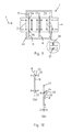
- FIG. 2 shown it is also possible, as in FIG. 2 shown to convey the boards substantially at an angle ⁇ through the furnace 1.
- mold apertures 9 are shown in more detail in FIG FIG. 3 ,
- FIG. 3 shows a mold panel 9 according to the invention in a plan view.
- the light metal component 2 passes in the transport direction 4, so based on the image plane in this, the mold aperture 9, wherein between the outer edge 10 of the light metal component 2 and the opening 11, a gap 12 remains to minimize it, so that as little as possible Air flow L can escape via the gap 12 from the temperature zones Z1, Z2 or from the inlet E or outlet A of the furnace 1.
- the light metal component 2 according to FIG. 3 has an asymmetric configuration, but it is also possible to lead large and small square boards by replacing the mold aperture 9 through the furnace 1.
- FIG. 4 represented in which a small light metal component 2 is detected by the mold plate 9, and indicated by the dashed line, by exchanging the mold plate 9 also in the geometrical dimensions larger light metal component 2 is conveyed through the kiln 1, wherein between the light metal component 2 and the mold plate 9, a small gap 12 remains ,
- FIG. 5 a cross-sectional view through the furnace installation 1 according to the invention, wherein the light metal component 2 is conveyed through the furnace installation 1 in the transport direction 4 and in the cross-sectional view is a plan view of a mold panel 9 is shown. It is for example shown a cross section through the temperature zone Z1.
- a circulating air fan 13 that generates the air circulation within the temperature zone Z1.
- the air flow L circulated by the circulating air blower 13 passes through a heating register 14 where it is heated and subsequently flows via the light metal component 2.
- the air flow L is collected and in turn fed to the circulating air blower 13.
- Shown here are also additional heating units 15, with which it is possible to heat the air flow L in addition to or also to heat exclusively, so that the heat source upstream of the circulating air blower 13 and not like the heating coil 14 is connected downstream.
- FIG. 6 shows a furnace installation 1 according to the invention in a second embodiment, wherein the furnace 1 in turn has a conveyor (4) in the form of a conveyor belt 3, which conveys light metal components 2 in the form of boards 2, 2a, 2b, 2c in the transport direction 4 through the furnace 1.
- the light metal components 2 are positioned on the conveyor belt 3 and enter through an inlet E in the transport direction 4 in the furnace 1 a.
- a partitions 16 are arranged on the conveyor belt 3, wherein in each case between two partitions 16 shown here two light metal components 2 are arranged.
- An inventive feature of the second embodiment according to FIG. 6 is that even light metal components 2 with different geometries compared to a board 2, 2 a, 2 b, 2 c are transported through the furnace 1. Thus, it is possible, for example, to transport longer boards 2 a relative to the light metal components 2 through the furnace 1. It is also possible to convey corrugated or corrugated blanks 2b or even three-dimensionally shaped components 2c through the furnace installation.
- the partition walls 16 a seal at each inlet E and outlet A and between the temperature zones T, Z1, Z2 is made.
- FIG. 7 shows an analogous embodiment FIG. 6 , in which case only one light metal component 2, 2b, 2c is arranged between the partitions 16.
- the partitions 16 according to FIG. 6 and FIG. 7 are preferably placed before the entry E in the furnace 1 on the conveyor belt 3 and after the exit A from the kiln 1 of the conveyor belt 3 can be removed. As a result, the return 17 of the conveyor belt 3 is to be provided only with a small height h.
- FIG. 8 shows a third embodiment of the furnace installation 1 according to the invention, in which case relatively movable bulkheads 18 are present at the inlet E as well as at the outlet A and also at crossover Ü between the individual temperature zones T, Z1, Z2.
- Ü between the individual temperature zones T, Z1, Z2.
- the boards 2a, 2b are arranged on respective connectors 8 substantially at a 90 ° angle to the transport direction 4 on the conveyor belt 3.
- the respective relatively movable bulkheads 18 are in FIG. 8 illustrated in relation to the transport direction 4 and the furnace 1 formed upwardly movable relative.
- FIG. 9 shows a further embodiment variant with relatively movable bulkheads 19a, 19b, wherein the bulkheads 19a, 19b are formed here in two parts and are also arranged relatively movable in the furnace 1.
- the two-part bulkhead 19a, 19b thus performs with a part 19a a relative movement R to one side and with the second part 19b a relative movement R to the opposite side.
- FIG. 9 shown view of an inventive furnace system 1 from above thus allows the light metal components 2 by opening the bulkhead 19a, 19b a passage in the transport direction 4.
- the furnace 1 has two different temperature zones Z1, Z2, in each of which not shown in detail Air flow is recirculated and convectively treated by the furnace 1 conveyed light metal components 2 thermally.
- FIG. 9 shown furnace 1 a shell 20 which surrounds the entire furnace 1, wherein the bulkheads 19 a, 19 b are relatively movable within the shell 20.
- the front side of the two-part bulkhead 19a, 19b is shown, wherein here various types of sealing labyrinths 21 may be formed, the one Violation of the circulated air flow L1, L2, L3 and / or the heat between the two different temperature zones Z1, Z2, Z3 or to prevent leakage of heat from the inlet E or outlet A.
- the sealing labyrinths can be U-shaped or C-shaped in cross-section.
- FIGS. 10a and 10b a further embodiment of the relatively movable bulkhead 18 is shown, wherein the bulkhead 18 here through a slot 22 in the shell 20 perform the relative movement R.
- the bulkhead 18 is further shown coupled to an actuator 23 which performs the relative movement R as linear movement with only one coupling rod 24 passing through the slot 22 in the shell 20 so that the possible escape of airflow L1, L2, L3 and / or heat from the interior of the oven space is avoided.
Abstract
Description
Die vorliegende Erfindung betrifft eine Ofenanlage zum thermischen Behandeln von Leichtmetallbauteilen gemäß den Merkmalen im Oberbegriff von Patentanspruch 1, 16.The present invention relates to a furnace for the thermal treatment of light metal components according to the features in the preamble of
Die vorliegende Erfindung betrifft weiterhin ein Verfahren zum thermischen Behandeln von Leichtmetallbauteilen gemäß den Merkmalen im Oberbegriff von Patentanspruch 11, 25.The present invention further relates to a method for the thermal treatment of light metal components according to the features in the preamble of
Zur Herstellung von Kraftfahrzeugbauteilen ist bereits seit vielen Jahrzehnten der Einsatz von Blechbauteilen bekannt. Die Blechbauteile werden zunächst umgeformt und dann zu einzelnen Baugruppen bzw. zu einer gesamten Karosserie zusammengefügt. Kraftfahrzeugkarosserien sind heutzutage überwiegend als selbsttragende Karosserien ausgebildet, weshalb die Blechbauteile nicht nur ästhetische oder formgebende Aufgaben übernehmen, sondern auch Steifigkeitseigenschaften besitzen müssen, um der Kraftfahrzeugkarosserie im Betrieb eine hinreichende Steifigkeit zu verleihen. Ebenfalls werden an die Kraftfahrzeugstrukturbauteile Anforderungen an das Crashverhalten gestellt. So müssen sie durch gezielte Formung in einem Aufprallfall Aufprallenergie in Umformenergie dissipieren.For the manufacture of motor vehicle components, the use of sheet metal components has been known for many decades. The sheet metal components are first formed and then assembled into individual modules or to an entire body. Motor vehicle bodies are nowadays predominantly designed as self-supporting bodies, which is why the sheet metal components not only have to assume aesthetic or shaping tasks, but also have to possess rigidity properties in order to be able to do so Vehicle body in operation to give sufficient rigidity. Demands on the crash behavior are also made to the motor vehicle structural components. So they have to dissipate impact energy in forming energy by targeted shaping in an impact case.
Als bevorzugter Werkstoff hat sich Stahl aufgrund seiner günstigen Herstellbarkeit bei gleichzeitig hoher Steifigkeit herausgestellt. Insbesondere die Warmumform- und Presshärtetechnologie verleiht dem Stahl hochfeste oder gar höchstfeste Eigenschaften, weshalb es weiterhin möglich war, das spezifische Eigengewicht der Bauteile zu senken, und gleichzeitig die Festigkeitswerte zu erhöhen.As a preferred material steel has been found due to its low producibility at the same time high rigidity. In particular, the hot forming and press-hardening technology gives the steel high-strength or even very high-strength properties, which is why it was still possible to reduce the specific weight of the components, and at the same time to increase the strength values.
Heutzutage werden jedoch an Kraftfahrzeuge nicht nur ästhetische und sicherheitsrelevante Erwartungen gestellt, es werden vielmehr auch ökologische und wirtschaftliche Aspekte zum Betreiben des Kraftfahrzeugs in den Vordergrund gestellt. So ist es insbesondere wichtig, dass das Kraftfahrzeug einen geringen Kraftstoffverbrauch bei gleichzeitig ebenfalls geringem CO2-Ausstoß besitzt. Hierzu gibt es verschiedenste Ansätze, beispielsweise die Verwendung neuer Antriebsmethoden wie dem Hybridantrieb oder aber eine besondere Formgebung, sodass das Kraftfahrzeug einen geringen Luftwiderstand besitzt.Today, however, not only are aesthetic and safety-related expectations placed on motor vehicles, but also ecological and economic aspects for operating the motor vehicle are given priority. So it is particularly important that the motor vehicle has a low fuel consumption while also low CO2 emissions. For this purpose, there are various approaches, such as the use of new drive methods such as the hybrid drive or a special shape, so that the motor vehicle has a low air resistance.
Ein weiterer Ansatz ist die Verwendung von Leichtmetallbauteilen zur Senkung des spezifischen Eigengewichts der Kraftfahrzeugkarosserie und somit des gesamten Kraftfahrzeugs. Hierbei werden insbesondere Leichtmetallbauteile aus Aluminiumlegierungen eingesetzt.Another approach is the use of light metal components to reduce the specific weight of the vehicle body and thus the entire motor vehicle. In this case, in particular light metal components made of aluminum alloys are used.
Für bestimmte Anwendungen, beispielsweise bei hohen Umformgraden oder bei der Einstellung gezielter Festigkeitswerte in Aluminiumbauteilen ist es notwendig, die Platinen vor der Umformung und/oder in Zwischenstufen während der Umformung und/oder Formteile nach der Umformung thermisch zu beeinflussen.For certain applications, for example at high degrees of deformation or when setting specific strength values in aluminum components, it is necessary to thermally influence the boards before forming and / or in intermediate stages during forming and / or molded parts after forming.
Aus dem Stand der Technik sind Durchlauföfen bekannt, beispielsweise aus der
Werden solche Ofenanlagen jedoch für Leichtmetalllegierungen verwendet, sind einige Verfahren ineffizient, da das Aluminium z.B. die Wärmestrahlung reflektiert oder technisch unpraktikabel, da sich z.B. Formplatinen oder -teile nur ungleichmäßig erwärmen lassen und sich stark verziehen häufig aber vor allem stark verlustbehaftet, da ein großer Teil der eingebrachten Energie nicht genutzt wird. Ein weiterer Nachteil ist der hohe Platzbedarf der meisten Anlagen.However, when such furnaces are used for light alloys, some methods are inefficient because the aluminum is e.g. the thermal radiation is reflected or technically impractical since e.g. Form boards or parts can be heated only unevenly and warp badly often but above all, very lossy, since a large part of the introduced energy is not used. Another disadvantage is the high space requirements of most systems.
Die Ofenanlagen können mithin nur uneffektiv betrieben werden, was die Produktionskosten des ohnehin gegenüber Stahl teureren Leichtmetallwerkstoffs weiter steigert.Consequently, the furnace systems can only be operated inefficiently, which further increases the production costs of the already more expensive light metal material compared to steel.
Aufgabe der vorliegenden Erfindung ist es daher, ausgehend vom Stand der Technik, eine Ofenanlage zum thermischen Behandeln von Leichtmetallbauteilen sowie ein Verfahren zum Betreiben der Ofenanlage bereitzustellen, mit dem eine effiziente Massenfertigung von Leichtmetallbauteilen durchführbar ist und die kostengünstig betreibbar ist.Object of the present invention is therefore, starting from the prior art, to provide a furnace for the thermal treatment of light metal components and a method for operating the furnace, with the efficient mass production of light metal components can be carried out and which is inexpensive to operate.
Die zuvor genannte Aufgabe wird erfindungsgemäß mit einer Ofenanlage zum thermischen Behandeln von Leichtmetallbauteilen gemäß den Merkmalen im Patentanspruch 1 und 16 gelöst.The aforementioned object is achieved with a furnace for the thermal treatment of light metal components according to the features in
Der verfahrenstechnische Teil der Aufgabe wird weiterhin mit einem Verfahren zum thermischen Behandeln von Leichtmetallbauteilen gemäß den Merkmalen im Patentanspruch 11 und 25 gelöst.The procedural part of the object is further achieved by a method for the thermal treatment of light metal components according to the features in
Vorteilhafte Ausführungsvarianten der vorliegenden Erfindung sind Bestandteil der abhängigen Patentansprüche.Advantageous embodiments of the present invention are part of the dependent claims.
Die erfindungsgemäße Ofenanlage zum thermischen Behandeln von Leichtmetallbauteilen, wobei die Leichtmetallbauteile kontinuierlich durch die Ofenanlage beförderbar sind und die Ofenanlage eine Wärmequelle aufweist ist dadurch gekennzeichnet, dass in der Ofenanlage ein Luftstrom umwälzbar ist und mithin nur die an die Platine oder das Bauteil sowie als Verlustströme auftretende Energie nachgesetzt werden muss, wobei die Leichtmetallbauteile in der Ofenanlage konvektiv durch den Luftstrom erwärmbar sind und ein jeweils in die Ofenanlage eintretendes Leichtmetallbauteil und ein jeweils aus der Ofenanlage austretendes Leichtmetallbauteil als Dichtschott den Luftstrom an einem Entweichen aus der Ofenanlage hindern.The furnace system according to the invention for the thermal treatment of light metal components, wherein the light metal components are continuously conveyed through the furnace and the furnace has a heat source is characterized in that in the furnace system, an air flow is recirculated and therefore only those occurring to the board or the component and as leakage currents Energy must be replenished, the light metal components in the furnace convection are heated by the air flow and each entering the furnace light metal component and each exiting the furnace light metal component as a sealing bulkhead prevent the air flow from escaping from the furnace.
Die erfindungsgemäße Ofenanlage nutzt zum thermischen Behandeln, insbesondere zum Erwärmen der Leichtmetallbauteile das Konvektionsprinzip. Bei einem Leichtmetallbauteil kann es sich im Rahmen der Erfindung um ein bereits fertig umgeformtes Bauteil handeln, aber auch um ein Bauteil in einem Zwischenformstadium oder gar um eine Platine, die im Anschluss an die thermische Behandlung umgeformt wird.The furnace installation according to the invention uses the convection principle for thermal treatment, in particular for heating the light metal components. In the context of the invention, a light metal component may be an already completely formed component, but also a component in an intermediate molding stage or even a printed circuit board, which is formed after the thermal treatment.
Bevorzugt werden mit der erfindungsgemäßen Ofenanlage Leichtmetallbauteile aus einer Aluminiumlegierung, insbesondere aus einer Aluminiumknetlegierung behandelt. Die jeweiligen Bauteile werden auf einem zeitlich getaktet oder kontinuierlich laufenden Förderer gestellt, und treten dann einzeln hintereinander in gleichmäßigem Abstand und bevorzugt in regelmäßigen Abständen durch zusätzliche Schottblenden separiert in die Ofenanlage ein. Die Ofenanlage ist dabei in einem Eintritt derart ausgebildet, dass ein jeweils in die Ofenanlage eintretendes Leichtmetallbauteil sowie an einem Austritt eines jeweils aus der Ofenanlage austretendes Leichtmetallbauteil als Dichtschott fungiert, so dass der innerhalb der Ofenanlage umgewälzte Luftstrom nicht aus der Ofenanlage entweicht. Jeweils bei einem Übergang von einem Bauteil im Eintrittsbereich zu dem nächsten in den Eintrittsbereich eintretenden Bauteil, und bei analogem Prinzip am Austritt der Ofenanlage kommt es zu Verlusten aufgrund des Abstands der einzelnen Bauteile untereinander. Darüber hinaus treten Überströmverluste auch an einem Spalt zwischen Bauteil oder Schott und den angrenzenden Abschlüssen auf. Aufgrund der Möglichkeit, eine Anzahl von Bauteilen auf einer kurzen Strecke getaktet oder kontinuierlich durch die Ofenanlage zu fördern, können besonders kurze Taktzeiten von wenigen Sekunden realisiert werden, so dass mit der Ofenanlage effektiv große Mengen von thermisch zu behandelnden Leichtmetallbauteilen gehandhabt werden können.Light metal components made of an aluminum alloy, in particular of an aluminum wrought alloy, are preferably treated with the furnace installation according to the invention. The respective components are placed on a temporally clocked or continuously running conveyor, and then occur one behind the other at a uniform distance and preferably at regular intervals by additional bulkheads separated into the furnace system. In this case, the furnace installation is formed in an inlet such that a light metal component entering the furnace system as well as an outlet of a light metal component exiting from the furnace system acts as a sealing bulkhead, so that the air flow circulated within the furnace system does not escape from the furnace system. Each at a transition from a component in the inlet region to the next component entering the inlet region, and with analogous principle at the outlet of the furnace there are losses due to the distance between the individual components. In addition, overflow losses also occur at a gap between the component or bulkhead and the adjacent terminations. Due to the ability to clocked or continuously promote a number of components over a short distance through the furnace, particularly short cycle times of a few seconds can be realized so that the furnace system can effectively handle large quantities of thermally treated light metal components.
Im Rahmen der Erfindung ist bei dieser und allen nachfolgend beschriebenen Ausführungsvarianten der Ofenanlage eine Förderung der zu erwärmenden Bauteile derart möglich, dass die Förderung kontinuierlich durchgeführt wird, so dass keine Unterbrechung erfolgt. Somit werden kontinuierlich Bauteile am Eintritt der Ofenanlage auf das Förderband aufgesetzt, durch die Ofenanalage transportiert und am Austritt der Ofenanlage von den Transportern wieder entnommen.In the context of the invention, in this and all variants of the furnace installation described below, a delivery of the components to be heated is possible in such a way that the delivery is carried out continuously so that there is no interruption. Thus, components are placed on the conveyor belt continuously at the entrance of the furnace, transported through the furnace and removed at the exit of the furnace from the transporters again.
Im Rahmen der Erfindung ist die kontinuierliche Förderung dennoch auch derart zu verstehen, dass sie im Takt der Produktion mit vorgeschalteten und nachgeschalteten Produktionsanlagen arbeitet. Beispielsweise kann das Förderband jeweils zum Aufsetzen eines neuen Bauteils und dann auch gegebenenfalls zur gleichzeitigen Entnahme am Austritt der Ofenanlage des erwärmten Bauteils kurz angehalten werden und so dann wieder anfahren, bis zum nächsten Bauteil.In the context of the invention, the continuous promotion is still to be understood in such a way that it operates in the cycle of production with upstream and downstream production equipment. For example, the conveyor belt can be stopped briefly each for placing a new component and then optionally for simultaneous removal at the outlet of the furnace system of the heated component and then start again, until the next component.
Im Rahmen der Erfindung ist es auch möglich, die Fördergeschwindigkeit der Bauteile durch die Ofenanlage nicht nur in Abhängigkeit der Verweildauer der Bauteile innerhalb der Ofenanlage selbst zu wählen, sondern auch derart an den Produktionsprozess anzupassen, dass immer in einer ausreichenden Menge wärmebehandelte Bauteile zur Weiterverarbeitung bereitgestellt werden.In the context of the invention, it is also possible to choose the conveying speed of the components through the furnace not only depending on the residence time of the components within the furnace itself, but also adapt to the production process so that always provided in a sufficient amount of heat-treated components for further processing become.
Innerhalb der erfindungsgemäßen Ofenanlage sind eine oder mehrere Wärmequellen angeordnet, die mindestens eine vorbestimmte Temperatur erzeugen. Bei der Temperatur handelt es sich bevorzugt um eine Temperatur zwischen 100°C und 600°C, die dann durch eine Umwälzeinrichtung, insbesondere durch eine innerhalb der Ofenanlage angeordneten Luftumwälzeinrichtung in Verbindung mit einem in der Ofenanlage ausgebildeten Kanalsystem eine Luftströmung erzeugt, die über durch die Ofenanlage beförderten Leichtmetallbauteile strömt. Der erwärmte Luftstrom tauscht dann aufgrund der erzwungen Konvektion mit der Oberfläche der Leichtmetallbauteile Wärme aus, so dass es zu einem Wärmeübergang von Luftstrom zu Leichtmetallbauteil kommt. Hierbei nutzt die erfindungsgemäße Ofenanlage die hohe Wärmeleitfähigkeit von Aluminium in Verbindung mit der relativ zur Masse des Leichtmetallbauteils selber großen Oberfläche, so dass innerhalb kürzester Zeit eine thermische Behandlung, insbesondere eine Erwärmung des Leichtmetallbauteils durchführbar ist.Within the furnace installation according to the invention, one or more heat sources are arranged which generate at least one predetermined temperature. The temperature is preferably a temperature between 100 ° C. and 600 ° C., which then generates a flow of air through a circulating device, in particular through an air circulation device arranged inside the furnace in conjunction with a channel system formed in the furnace system Furnace transported light metal components flows. The heated air flow then exchanges heat due to the forced convection with the surface of the light metal components, so that there is a heat transfer from air flow to light metal component. In this case, the furnace system according to the invention uses the high thermal conductivity of aluminum in conjunction with the relatively large surface relative to the mass of the light metal component, so that within a very short time a thermal treatment, in particular a heating of the light metal component is feasible.
Am Austritt der Ofenanlage ist dann wieder ein Austrittsbereich derart ausgebildet, dass der Luftstrom an einem Entweichen aus der Ofenanlage durch die aus der Ofenanlage austretenden Leichtmetallbauteile gehindert wird.At the outlet of the furnace then an exit region is again formed such that the air flow is prevented from escaping from the furnace by the emerging from the furnace light metal components.
Für die Konvektionsbeheizung können sowohl fremderwärmte Luft als auch heiße Abgasströme genutzt werden. Der Luftstrom kann im Rahmen der Erfindung jede Art von Gasstrom sein, beispielsweise auch der Strom eines Reaktionsgases.For the convection heating, both foreign-heated air and hot exhaust gas streams can be used. Within the scope of the invention, the air stream may be any type of gas stream, for example also the stream of a reaction gas.
Insgesamt bietet die erfindungsgemäße Ofenanlage den Vorteil, dass nicht die gesamte Anlage gerade bei einem Anfahren zu Produktionsbeginn zunächst aufgeheizt werden muss, sondern lediglich die in der Ofenanlage umgewälzte Luft muss entsprechend temperiert werden. Die erfindungsgemäße Ofenanlage kann somit mit einem effektiven Wirkungsgrad arbeiten, bei deutlich geringeren Energiekosten in Relation zu einer Erwärmungsanlage, die nach dem Wärmestrahlungs- oder aber auch dem Induktionsprinzip arbeitet. Gerade durch das Umwälzen des Luftstroms und das Verhindern des Entweichen des Luftstroms ist es in Verbindung mit einer thermischen Kapselung der Ofenanlage möglich, den einmal erwärmten Luftstrom durch die Wärmequelle beim Umwälzen immer wieder nur gering nachzuerwärmen, wodurch die Energiekosten beim Betreiben der erfindungsgemäßen Ofenanlage sehr gering sind.Overall, the furnace installation according to the invention has the advantage that the entire installation does not first have to be heated when it starts up at the start of production, but only the air circulated in the furnace installation has to be appropriately tempered. The furnace system according to the invention can thus work with an effective efficiency, at significantly lower energy costs in relation to a heating system that operates on the heat radiation or even the induction principle. Just By circulating the air flow and preventing the escape of the air flow, it is possible, in conjunction with a thermal encapsulation of the furnace, to reheat the once heated air flow through the heat source again and again only slightly, as a result of which the energy costs during operation of the furnace installation according to the invention are very low ,
Insbesondere ist die Wärmequelle als Elektroheizung ausgebildet und/oder als Brennstoffheizung. Die Wärmequelle ist innerhalb der Ofenanlage nach und/oder vor der Umwälzanlage eingerichtet. Der so erwärmte Luftstrom oder Gasstrom wird besonders bevorzugt direkt an die Leichtmetallbauteile weitergegeben, so dass keine Strömungsverluste zwischen direkt von der Wärmequelle erwärmtem Luftstrom und einem langen Strömungskanalsystem entstehen. Nach Passieren des Luftstroms der Leichtmetallbauteile trifft dieser auf ein Kanalsystem und wird wiederum der Umwälzeinrichtung zugeführt, wobei er kurz vor oder nach der Umwälzeinrichtung dann wiederum durch eine dort angeordnete Wärmquelle auf die gewünschte Temperatur nacherwärmt wird.In particular, the heat source is designed as an electric heater and / or as a fuel heater. The heat source is installed inside the furnace after and / or in front of the circulation system. The thus heated air flow or gas flow is particularly preferably passed directly to the light metal components, so that no flow losses between heated directly from the heat source air flow and a long flow channel system. After passing through the air flow of the light metal components, this meets a channel system and in turn is supplied to the circulation device, wherein it is reheated shortly before or after the circulation then again by a heat source arranged there to the desired temperature.
Die Wahl der Wärmequelle als Elektroheizung oder aber als Brennstoffheizung ist insbesondere von der Energieverfügbarkeit, den Energiekosten sowie der Größe der erfindungsgemäßen Ofenanlage abhängig. Bei kleineren Stückzahlen ist es sinnvoll, eine Elektroheizung zu verwenden. Im Rahmen der Erfindung können jedoch auch beide Heizungsarten kombiniert werden, so dass die Ofenanlage modular für verschiedene Einsatzzwecke nutzbar ist.The choice of the heat source as an electric heater or as a fuel heater is particularly dependent on the energy availability, the energy costs and the size of the furnace installation according to the invention. For smaller quantities, it makes sense to use an electric heater. In the context of the invention, however, both types of heating can be combined, so that the furnace system can be used modularly for various purposes.
Weiterhin bevorzugt sind die Umwälzeinrichtungen als Umluftgebläse innerhalb der Ofenanlage angeordnet. Je nach zu erzeugender Temperatur können die Umluftgebläse beispielsweise auch erst in dem Kanalsystem oder aber nach Passieren des Luftstroms der Leichtmetallbauteile angeordnet sein, so dass der zunächst mitunter bis zu 600° C heiße Luftstrom oder Gasstrom sich an den Leichtmetallbauteilen abgekühlt hat, bevor er die Umluftgebläse passiert. Die Umluftgebläse sind somit nicht den Temperaturmaxima von mehr als 400° C oder gar mehr als 500° C ausgesetzt, sondern können in einem warmen Luftstrom bei circa 100° C bis 400° C betrieben werden.Further preferably, the circulating means are arranged as circulating air blowers within the furnace. Depending on the temperature to be generated, the circulating air blowers may for example also be arranged in the duct system or after passing through the air flow of the light metal components, so that the initially sometimes up to 600 ° C hot air flow or gas flow has cooled to the light metal components, before he the circulating air blower happens. The circulating air fans are thus not the temperature maxima of more than 400 ° C or even more than 500 ° C exposed, but can be operated in a warm air flow at about 100 ° C to 400 ° C.
Im Rahmen der Erfindung sind die Umluftgebläse dann in verschiedenen Gebläsestufen nutzbar, so dass die Luft- oder Gasstromgeschwindigkeit, mit der der Luftstrom über die Leichtmetallbauteile strömt, einstellbar ist. Dieser erlaubt in Verbindung mit einer Temperaturregelung zwei Einstellparameter, so dass die Erwärmung der Leichtmetallbauteile durch die Strömungsgeschwindigkeit und/oder die Temperatur des Luftstroms einstellbar sind.In the context of the invention, the circulating air blower can then be used in different blower stages, so that the air or gas flow velocity with which the air flow flows over the light metal components is adjustable. This allows in conjunction with a temperature control two adjustment parameters, so that the heating of the light metal components by the flow velocity and / or the temperature of the air flow can be adjusted.
Weiterhin bevorzugt ist die Ofenanlage thermisch gekapselt, wobei weiterhin bevorzugt an dem Eintritt und/oder dem Austritt der Ofenanlage Dichtelemente angeordnet sind, wobei die Dichtelemente ganz besonders bevorzugt als austauschbare Formblenden ausgebildet sind. Die thermische Kapselung ist beispielsweise eine Mantelisolierung der Ofenanlage, so dass Restwärme nicht nach Passieren der Leichtmetallbauteile oder aber bei Passieren des Kanalsystems aus der Ofenanlage entweicht.Further preferably, the furnace system is thermally encapsulated, wherein further preferably at the inlet and / or outlet of the furnace sealing elements are arranged, wherein the sealing elements are very particularly preferably designed as exchangeable mold panels. The thermal encapsulation is, for example, a jacket insulation of the furnace, so that residual heat does not escape after passing through the light metal components or when passing the channel system from the furnace.
Weiterhin ist gerade bei der getakteten oder kontinuierlichen Massenförderung von Leichtmetallbauteilen in die Ofenanlage hinein und aus der Ofenanlage heraus der Eingangs- und der Ausgangsbereich, mithin der Eintritt und der Austritt, kritisch, da hier Wärme, aber auch aufgrund des Konvektionsprinzip der erfindungsgemäßen Ofenanlage der Luftstrom entweichen kann. Hierzu sind der Eintritt und der Austritt jeweils so ausgebildet, dass aufeinander folgende Leichtmetallbauteile, die kontinuierlich in die Ofenanlage eintreten bzw. aus dieser austreten, den Eintritt und/oder den Austritt derart abdichten, dass eine zu geringe Luftmenge des innerhalb der Ofenanlage zirkulierenden Luftstroms entweicht. Unvermeidbar durch Spalte an Ein- und Austritt nach außen übertretender heißer Luft-/Gasstrom kann durch übergreifende Hauben aufgefangen und der Umwälzung wieder zugeführt werden, wodurch sich der Wirkungsgrad weiter steigern lässt.Furthermore, especially in the pulsed or continuous mass production of light metal components in the furnace system and out of the furnace out the input and the output area, thus the inlet and the outlet, critical, since heat, but also due to the convection principle of the furnace system according to the invention the air flow can escape. For this purpose, the inlet and the outlet are each designed so that successive light metal components that continuously enter the furnace system or emerge from this, the inlet and / or the outlet seal such that too small an amount of air circulating within the furnace air flow escapes , Unavoidable hot air / gas flow passing through gaps at the inlet and outlet can be collected by means of overlapping hoods and returned to the circulation, whereby the efficiency can be further increased.
Bei Nutzung der Bauteilgeometrie zur Abdichtung zur Erhöhung der Dichtigkeit sind Dichtelemente an dem Eintritt und/oder an dem Austritt ausgebildet, wobei die Dichtelemente bevorzugt als Formblende ausgebildet sind. Bei Verwendung verschiedener Leichtmetallbauteile, insbesondere bei verschieden großen Platinen ist es somit durch Austausch der Formblenden möglich, dass jeweils die Querschnittsfläche bzw. die orthogonal zur Förderrichtung sich aufspannende Querspantfläche der Leichtmetallbauteile derart durch die Formblenden abzubilden, dass an einem umlaufenden Randbereich nur ein geringes Spaltmaß entsteht. Die erfindungsgemäße Ofenanlage ist somit optional für Leichtmetallbauteile mit verschiedenen geometrischen Abmessungen nutzbar.When using the component geometry for sealing to increase the tightness of sealing elements are formed at the inlet and / or at the outlet, wherein the sealing elements are preferably formed as a form of aperture. When using different light metal components, in particular with different sized boards, it is thus possible by replacing the mold apertures that each map the cross-sectional area or orthogonal to the conveying direction spanning transverse surface of the light metal components through the mold apertures such that only a small gap occurs at a peripheral edge region , The furnace system according to the invention is thus optionally available for light metal components with different geometric dimensions.
Weiterhin bevorzugt sind in der Ofenanlage mindestens zwei Temperaturzonen ausgebildet, wobei die Leichtmetallbauteile als Dichtschott zwischen den Zonen nutzbar sind, insbesondere sind an einem Übertritt zwischen den Zonen austauschbare Formblenden angeordnet. Im Rahmen der Erfindung ist somit bei einer Ofenanlage mit zwei voneinander verschiedenen Temperaturzonen eine erste Temperaturzone und eine zweite Temperaturzone derart ausgebildet, dass das jeweils von der einen Zone in die andere Zone übertretende Leichtmetallbauteil als Dichtschott eines Übertritts, analog dem Prinzip am Eintritt oder aber am Austritt der Ofenanlage fungiert. Auch hier sind austauschbare Formblenden angeordnet, so dass bei Leichtmetallbauteilen mit voneinander verschiedenen geometrischen Abmessungen eine hohe Luftdichtigkeit auch zwischen den Zonen ausgebildet ist.Furthermore, at least two temperature zones are preferably formed in the furnace installation, wherein the light metal components can be used as a sealing bulkhead between the zones, in particular interchangeable mold panels are arranged at a transition between the zones. In the context of the invention, a first temperature zone and a second temperature zone is thus formed in an oven with two different temperature zones such that each passing from one zone to the other zone light metal component as a sealing bulkhead of a crossing, analogous to the principle at the entrance or on Exit the furnace system acts. Again, interchangeable mold panels are arranged so that in light metal components with different geometric dimensions from each other high air tightness is also formed between the zones.
In den jeweiligen Temperaturzonen kann dann wiederum durch Wahl der Luftströmungsgeschwindigkeit und/oder der Lufttemperatur eine voneinander verschiedene thermische Wärmebehandlung erfolgen. Im Rahmen der Erfindung können dann beispielsweise auch zwei Umluftgebläse angeordnet sein, die in der jeweiligen Zone voneinander verschiedene Strömungsgeschwindigkeiten erzeugen. Ebenfalls können zwei Wärmequellen zur Erzeugung verschiedener Temperaturen innerhalb der Ofenanlage angeordnet sein. Im Rahmen der Erfindung kann die Ofenanlage auch 3, 4, 5 oder mehr Zonen aufweisen, wobei es wiederum möglich ist, entsprechend einer jeden Zone ein Umluftgebläse und eine Wärmequelle zuzuordnen. Im Rahmen der Erfindung ist es ebenfalls möglich, über veränderliche Querschnittsdüsen an den Zonen zugeordneten Luftdüsen die Strömungsgeschwindigkeit innerhalb einer jeweiligen Zone individuell einzustellen, so dass nur ein Umluftgebläse verwendet wird. Im Rahmen der Erfindung kann eine Temperaturzone auch als eine Abkühlzone ausgebildet sein, so dass hier ein in Relation zu der Wärmebehandlungszone kalter Luftstrom von beispielsweise nur 50° C oder aber auch von nur 10° C die Leichtmetallbauteile umströmt.In turn, in the respective temperature zones, a different thermal heat treatment can take place by selecting the air flow velocity and / or the air temperature. In the context of the invention, two circulating air fans can then also be arranged, for example, which generate different flow velocities in the respective zone. Also, two heat sources can be used to generate different temperatures within the furnace be arranged. In the context of the invention, the furnace installation can also have 3, 4, 5 or more zones, wherein it is again possible to assign a circulating-air blower and a heat source corresponding to each zone. In the context of the invention, it is likewise possible to adjust the flow velocity within a respective zone individually by way of variable cross-sectional nozzles at the zones associated with the zones, so that only one circulating-air blower is used. In the context of the invention, a temperature zone may also be formed as a cooling zone, so that here flows around in relation to the heat treatment zone cold air flow of, for example, only 50 ° C or even only 10 ° C, the light metal components.
Besonders bevorzugt weisen die Formblenden eine Öffnung auf, die im Wesentlichen einer orthogonal zu der Förderrichtung angeordneten Querspantfläche der Leichtmetallbauteile entsprechen. Hiermit wird sichergestellt, dass auch bei einer leicht schräg gestellten Leichtmetallplatine nur geringe Spaltmaße beim Durchtritt der Platine durch die Formblende gegeben sind, so dass eine Verlustströmung der Luft vermieden wird.Particularly preferably, the mold apertures on an opening, which correspond substantially to an orthogonal to the conveying direction arranged transverse surface of the light metal components. This ensures that even with a slightly inclined light metal plate only small gaps in the passage of the board through the mold aperture are given, so that a loss of air flow is avoided.
Weiterhin weist die Ofenanlage im Bereich ihres Eintritts eine Trocknungszone auf und/oder im Bereich ihres Austritts eine Abkühlzone. Hierdurch ist es möglich, in der Trocknungszone zunächst ein auf den Leichtmetallbauteilen befindliches Schmiermittel oder eine sonstige Beschichtung zu trocknen oder aber von den Leichtmetallbauteilen zu entfernen. Anschließend werden die Leichtmetallbauteile in der mindestens einen Temperaturzone thermisch behandelt und optional dann in einer am Austritt der Ofenanlage befindlichen Abkühlzone wiederum abgekühlt. Die Abkühlung kann dabei auf eine Bauteiltemperatur von 100° C oder gar 50° C oder auch auf Raumtemperatur erfolgen. Hierdurch kann z.B. eine thermische Behandlung, Lösungsglühung, Auslagerung, Rückglühung, kontrolliert abgeschlossen werden.Furthermore, the furnace installation has a drying zone in the region of its inlet and / or a cooling zone in the region of its outlet. This makes it possible to first dry in the drying zone located on the light metal components lubricant or other coating or to remove it from the light metal components. Subsequently, the light metal components are thermally treated in the at least one temperature zone and optionally then cooled again in a cooling zone located at the outlet of the furnace. The cooling can be carried out at a component temperature of 100 ° C or even 50 ° C or even at room temperature. As a result, e.g. a thermal treatment, solution annealing, aging, annealing, controlled to be completed.
Weiterhin bevorzugt wird der umgewälzte Luftstrom innerhalb der Ofenanlage beim Passieren der Leichtmetallbauteile flächig über diese geleitet, so dass der Luftstrom die Leichtmetallbauteile flächig überströmt. Während des Überströmens findet dabei ein Wärmeaustausch der erwärmten/kalten Luft oder des warmen Gases auf das in Relation hierzu kältere oder wärmere Leichtmetallbauteil statt. Im Rahmen der Erfindung wird insbesondere die Vorderseite, aber auch aufgrund des kontinuierlichen Passierens des Leichtmetallbauteils dessen Rückseite von dem Luftstrom überströmt, so dass eine gleichmäßige Erwärmung von beiden Seiten stattfindet. Die jeweils in dem Leichtmetallbauteil eingestellte Temperatur kann dann wiederum durch Wahl von voneinander verschiedenen Lufttemperaturen oder aber auch von voneinander verschiedenen Strömungsgeschwindigkeiten eingestellt werden. Dabei ist es möglich, bei nur einer Temperaturzone die Parameter Temperatur und Strömungsgeschwindigkeit zu verstellen, so dass verschiedene Bauteile auf der gleichen Ofenanlage thermisch behandelbar sind. Im Falle von zwei oder mehr Temperaturzonen ist es auch möglich, die Strömungsgeschwindigkeit sowie die Temperatur in jeder einzelnen Zone individuell einzustellen.Further preferably, the circulated air flow within the furnace system when passing the light metal components is guided over this area, so that the air flow flows over the light metal components areally. During the Overflow takes place in this case a heat exchange of the heated / cold air or the warm gas to the colder or warmer in this light metal component instead. In the context of the invention, in particular the front side, but also due to the continuous passing of the light metal component whose rear surface is overflowed by the air flow, so that a uniform heating takes place from both sides. The respectively set in the light metal component temperature can then be adjusted in turn by selecting mutually different air temperatures or else from different flow rates. It is possible to adjust the parameters of temperature and flow rate in only one temperature zone, so that different components on the same furnace system are thermally treated. In the case of two or more temperature zones, it is also possible to individually adjust the flow rate and the temperature in each individual zone.
Weiterhin bevorzugt werden die Leichtmetallbauteile auf einem Transportband, insbesondere auf einem Kettenförderer, durch die Ofenanlage transportiert. Im Rahmen der Erfindung weist das Transportband, insbesondere der Kettenförderer, Aufnahmen mit Fixierungen auf, in die die Leichtmetallbauteile, insbesondere in Form von Platinen im Wesentlichen vertikal orientiert lagerbar sind. Darüber hinaus wird die Anlage hierdurch kompakter. so dass die Luftströmung die Bauteile im Wesentlichen in die vertikale Orientierung von unten nach oben oder aber von oben nach unten überströmt. Die Transportrichtung erfolgt dann im Wesentlichen in horizontaler Richtung, so dass die vertikal orientierten Bauteile zwischen den Zonen und am Eintritt und am Austritt die jeweilige Strömungsleit- und Dichtfunktion übernehmen. Bauteile in einem Winkel anordnenbar.Furthermore, the light metal components are preferably transported on a conveyor belt, in particular on a chain conveyor, through the furnace system. In the context of the invention, the conveyor belt, in particular the chain conveyor, recordings with fixations, in which the light metal components, in particular in the form of boards are substantially vertically oriented storable. In addition, the system becomes more compact. so that the air flow flows over the components substantially in the vertical orientation from bottom to top or from top to bottom. The transport direction is then substantially in the horizontal direction, so that the vertically oriented components between the zones and at the inlet and at the outlet take over the respective Strömungsleit- and sealing function. Components can be arranged at an angle.
Bevorzugt sind die Leichtmetallbauteile selber auf eine Temperatur zwischen 200° und 450° C innerhalb der Ofenanlage erwärmbar. Hierbei finden dann metallurgische Prozesse der jeweils verwendeten Aluminiumlegierung, insbesondere Aluminiumknetlegierung statt, die später eine gute Umformbarkeit oder aber ein entsprechendes homogenes Gefüge mit den gewünschten Festigkeitseigenschaften erzeugt.Preferably, the light metal components themselves are heatable to a temperature between 200 ° and 450 ° C within the furnace. Here then find metallurgical processes of the aluminum alloy used in each case, in particular aluminum wrought alloy, which later produces a good formability or a corresponding homogeneous structure with the desired strength properties.
Die vorliegende Erfindung betrifft weiterhin ein Verfahren zum thermischen Behandeln von Leichtmetallbauteilen in einer Ofenanlage, wobei die Ofenanlage mindestens eines der zuvor genannten Merkmale aufweist und das Verfahren folgende Verfahrensschritte umfasst:
- Bestücken eines Transportbandes mit einer Vielzahl von hintereinander gereihten Leichtmetallbauteilen, insbesondere Leichtmetallplatinen
- Befördern der Leichtmetallbauteile durch die Ofenanlage, wobei an einem Eintritt der Ofenanlage die Eintrittsöffnung durch das jeweils die Eintrittsöffnung passierende Leichtmetallbauteil abgedichtet wird,
- Erzeugen eines kontinuierlich umgewälzten warmen Luftstromes und Überströmen der Leichtmetallbauteile in mindestens einer Temperaturzone innerhalb der Ofenanlage, während das Leichtmetallbauteil getaktet oder kontinuierlich weiter durch die Ofenanlage transportiert wird,
- Austreten der thermisch behandelten Leichtmetallbauteile aus der Ofenanlage, wobei an einem Austrittsbereich der Ofenanlage eine Austrittsöffnung durch das jeweils die Austrittsöffnung passierende Leichtmetallbauteil abgedichtet wird.
- Equipping a conveyor belt with a plurality of successively lined light metal components, in particular light metal blanks
- Conveying the light metal components through the furnace installation, the inlet opening being sealed by the light metal component passing through the inlet opening at each inlet of the furnace installation,
- Generating a continuously circulated warm air flow and overflow of the light metal components in at least one temperature zone within the furnace plant, while the light metal component is clocked or continuously transported through the furnace,
- Exiting the thermally treated light metal components from the furnace, wherein at an outlet region of the furnace system, an outlet opening is sealed by the respectively passing the outlet opening light metal component.
Mit dem erfindungsgemäßen Verfahren ist es möglich, insbesondere hintereinander gereihte Leichtmetallbauteile, ganz besonders bevorzugt Leichtmetallplatinen auf einem Transportband bereitzustellen und kontinuierlich durch eine Ofenanlage zu führen. Innerhalb der Ofenanlage wird dann ein warmer Luft- oder Gasstrom mit Hilfe einer Wärmequelle erzeugt und durch ein Umluftgebläse in Zirkulation versetzt, so dass der warme Luft- oder Gasstrom die Leichtmetallbauteile überströmt. Das Leichtmetallbauteil selber erwärmt sich dann aufgrund der an der Oberfläche des Leichtmetallbauteils, insbesondere an einer Oberseite und auch einer Unterseite des Leichtmetallbauteils erzwungenen Konvektion, wodurch sich das Leichtmetallbauteil, insbesondere bei Verwendung einer Aluminiumlegierung aufgrund der guten Wärmeleitfähigkeit in besonders kurzer Zeit von mitunter nur wenigen Sekunden erwärmen lässt.With the method according to the invention, it is possible, in particular light alloy components arranged one behind the other, very particularly preferably to provide light metal blanks on a conveyor belt and to guide them continuously through a furnace installation. Within the furnace, a warm air or gas stream is then generated by means of a heat source and circulated by a circulating air blower, so that the warm air or Gas stream overflows the light metal components. The light metal component itself then heats up due to convection forced on the surface of the light metal component, in particular on an upper side and also a lower side of the light metal component, whereby the light metal component, in particular when using an aluminum alloy due to the good thermal conductivity in a very short time of sometimes only a few seconds warm up.
Erfindungsgemäß ist vorgesehen, dass an einem Eintritt und auch an einem Austritt der Ofenanlage die jeweilige Eintrittsöffnung bzw. Austrittsöffnung durch das jeweilig passierende Leichtmetallbauteil abgedichtet wird, so dass der innerhalb der Ofenanlage erzeugte Luft- oder Gasstrom kaum an die die Ofenanlage umgebende Luft entweicht. Im Rahmen der Erfindung können dann auch jeweils zwei oder drei die Eintrittsöffnung nacheinander passierende Leichtmetallbauteile gleichsam eine Dichtfunktion übernehmen. Gleiches gilt für die Austrittsöffnung.According to the invention, the respective inlet opening or outlet opening is sealed by the respectively passing light metal component at an inlet and also at an outlet of the furnace system, so that the air or gas flow generated within the furnace system hardly escapes to the air surrounding the furnace. In the context of the invention, two or three light metal components passing successively through the inlet opening can then assume a sealing function, as it were. The same applies to the outlet opening.
Innerhalb der Ofenanlage selber ist es möglich, durch Wahl der Strömungsgeschwindigkeit des Luft- oder Gasstroms und/oder der Luft- oder Gastemperatur des Luft- oder Gasstroms die Erwärmung des Leichtmetallbauteils einzustellen. Auch können zwei, drei oder mehr Temperaturzonen innerhalb der Ofenanlage unterteilt sein, wobei in jeder Zone dann durch die Parameter Strömungsgeschwindigkeit des Luftstroms oder aber auch Temperatur des Luftstroms unterschiedliche Erwärmungseffekte an dem Leichtmetallbauteil ausgeführt werden.Within the furnace itself, it is possible to adjust the heating of the light metal component by selecting the flow rate of the air or gas stream and / or the air or gas temperature of the air or gas stream. Also, two, three or more temperature zones may be subdivided within the furnace system, wherein in each zone then different heating effects are carried out on the light metal component by the parameters flow velocity of the air flow or else the temperature of the air flow.
Die thermisch behandelten Leichtmetallbauteile können im Rahmen der Erfindung insbesondere in einer Taktzeit von weniger als 15 Sekunden pro Bauteil einem weiteren Verarbeitungsverfahren zugeführt werden.The thermally treated light metal components can be supplied in the context of the invention, in particular in a cycle time of less than 15 seconds per component to another processing method.
Weiterhin bevorzugt weist die Ofenanlage eine Trocknungszone sowie eine Abkühlzone auf, wobei in der Trocknungszone die die Trocknungszone passierenden Leichtmetallbauteile getrocknet werden, insbesondere wird ein auf den Leichtmetallbauteilen vorhandenes Schmiermittel abgetrocknet. Ferner kann in einer Abkühlzone das Leichtmetallbauteil auf eine Kaltauslagerungstemperatur abgekühlt werden. Im Rahmen der Erfindung ist besonders bevorzugt eine Abkühlzone am Ende der Ofenanlage angeordnet, es können jedoch auch zwischen den einzelnen Temperaturzonen eine oder mehrere Abkühlzonen angeordnet werden, so dass ein erwärmtes Bauteil abgekühlt wird und anschließend wieder erwärmt wird.Further preferably, the furnace has a drying zone and a cooling zone, wherein in the drying zone, the light metal components passing through the drying zone are dried, in particular a Dried on the light metal components existing lubricant. Furthermore, in a cooling zone, the light metal component can be cooled to a cold aging temperature. In the context of the invention, a cooling zone is particularly preferably arranged at the end of the furnace installation, however, one or more cooling zones can also be arranged between the individual temperature zones so that a heated component is cooled and subsequently reheated.
Weiterhin bevorzugt werden bei dem erfindungsgemäßen Verfahren die in der Ofenanlage, insbesondere im Eintritt und im Austritt, aber auch an einem Übertritt zwischen den Zonen im Falle einer Mehrzonenofenanlage angeordneten Formblenden in Abhängigkeit der zu behandelnden Leichtmetallbauteile ausgetauscht. Die Formblenden werden insbesondere derart gewählt, dass eine Querspantfläche, welche orthogonal zur Transportrichtung angeordnet ist, in Verbindung mit dem jeweils die Formblende passierenden Leichtmetallbauteil oder aber auch mit zwei oder drei passierenden Leichtmetallbauteilen bestmöglich abdichtet, so dass der Luftstrom nicht entweichen kann.Furthermore, in the method according to the invention, the mold apertures arranged in the furnace installation, in particular in the inlet and outlet, but also at a transition between the zones in the case of a multi-zone furnace installation, are preferably exchanged depending on the light metal components to be treated. The mold apertures are selected in particular such that a transverse cutting surface, which is arranged orthogonally to the transport direction, seals in the best possible manner in conjunction with the light metal component passing through the mold aperture or even with two or three passing light metal components, so that the air flow can not escape.
Die zuvor genannten Merkmale sind im Rahmen der Erfindung beliebig untereinander kombinierbar mit den damit einhergehenden Merkmalen, ohne deren Rahmen zu verlassen. Ebenfalls sind die zuvor beschriebenen Parameter auf die nachfolgend beschriebenen Ausführungsformen uneingeschränkt anwendbar.The aforementioned features can be combined with each other in the context of the invention with the associated features without departing from their scope. Also, the parameters described above are fully applicable to the embodiments described below.
In einer weiteren Ausführungsvariante wird die erfindungsgemäße Aufgabe mit einer Ofenanlage zum thermischen Behandeln von Leichtmetallbauteilen, wobei die Leichtmetallbauteile kontinuierlich durch die Ofenanlage beförderbar sind und die Ofenanlage eine Wärmequelle aufweist, dadurch gelöst, dass in der Ofenanlage ein Luftstrom umwälzbar ist, wobei die Leichtmetallbauteile in der Ofenanlage konvektiv durch den Luftstrom erwärmbar sind und die Leichtmetallbauteile auf einer Fördereinrichtung durch die Ofenanlage transportierbar sind, wobei in Abständen zueinander Trennwände auf der Fördereinrichtung angeordnet sind und mindestens ein Leichtmetallbauteil zwischen zwei Trennwänden anordnenbar ist.In a further embodiment, the object of the invention with a furnace for the thermal treatment of light metal components, wherein the light metal components are continuously conveyed through the furnace and the furnace has a heat source, achieved in that in the furnace system, an air flow is recirculated, wherein the light metal components in the Furnace convection are heated by the air flow and the light metal components can be transported on a conveyor through the furnace system, wherein at intervals to each other partitions on the Conveyor are arranged and at least one light metal component between two partitions can be arranged.
Die bereits zuvor genannten Merkmale bezüglich beispielsweise unterschiedlicher Temperaturzonen, der Wärmequelle selber, der Strömungsgeschwindigkeit oder Luftstromtemperatur oder aber auch der Dichtelemente in Form von Formblenden sind auch mit der zweiten Ausführungsvariante kombinierbar, ohne dabei den Rahmen der Erfindung zu verlassen. Im Unterschied zur ersten Ausführungsvariante, in der die Leichtmetallbauteile selber als Dichtschott angeordnet sind, werden in der zweiten Ausführungsvariante entsprechende Trennwände auf der Fördereinrichtung angeordnet. Im Rahmen der Erfindung ist es jedoch auch möglich, eine Mischform aus der ersten und der zweiten Ausführungsvariante auszubilden, wonach die Trennwände jeweils als größeres Leichtmetallbauteil in der Ofenanlage erwärmt werden und zwischen den Trennwänden, mithin zwischen den größeren Leichtmetallbauteilen, kleinere Leichtmetallbauteile oder aber auch komplex geformte Leichtmetallbauteile anordnenbar sind.The above-mentioned features with respect to, for example, different temperature zones, the heat source itself, the flow velocity or air flow temperature or even the sealing elements in the form of mold apertures can also be combined with the second embodiment, without departing from the scope of the invention. In contrast to the first embodiment, in which the light metal components themselves are arranged as a sealing bulkhead, corresponding partitions are arranged on the conveyor in the second embodiment. In the context of the invention, however, it is also possible to form a hybrid form of the first and the second embodiment, after which the partitions are each heated as a larger light metal component in the furnace and between the partitions, hence between the larger light metal components, smaller light metal components or even complex molded light metal components are arrangeable.
Gerade hierdurch ergibt sich auch der Vorteil der zweiten Ausführungsvariante, wonach zwischen den beiden Trennwänden jeweils Leichtmetallbauteile anordnenbar sind, die verschieden große Bauteilabmessungen aufweisen können, wobei die äußere Geometrie der Leichtmetallbauteile kleiner sein muss als die äußeren Abmessungen der Trennwände, so dass in einem kontinuierlichem Beförderungsprozess die Trennwände eine dichtende Funktion einnehmen und die Leichtmetallbauteile nicht über die Trennwände hinüberstehen.This is also the advantage of the second embodiment, according to which light metal components can be arranged between the two partitions, which may have different sized component dimensions, the outer geometry of the light metal components must be smaller than the outer dimensions of the partitions, so that in a continuous transport process the partitions occupy a sealing function and the light metal components do not protrude beyond the partitions.
Ferner ist es möglich, gleichzeitig zwei, drei oder auch vier oder mehr Leichtmetallbauteile zwischen zwei Trennwänden anzuordnen und gleichzeitig wärmezubehandeln, wobei die Leichtmetallbauteile auch dreidimensional komplex geformte Geometrien aufweisen können.Furthermore, it is possible to arrange at the same time two, three or even four or more light metal components between two partition walls and at the same time heat treat, wherein the light metal components can also have three-dimensional complex shaped geometries.
Im Rahmen der Erfindung kann die Ofenanlage bei dem Einsatz von Trennwänden und dem Anordnen von mindestens einem Leichtmetallbauteile jeweils zwischen zwei Trennwänden für verschiedene Produktionsserien genutzt werden, ohne dabei umgerüstet werden zu müssen. So ist es beispielsweise möglich, in ihren äußeren Abmessungen voneinander verschieden große Leichtmetallbauteile, insbesondere Leichtmetallplatinen, direkt nacheinander durch die erfindungsgemäße Ofenanlage zu befördern, wobei die Dichtfunktion durch die Trennwände übernommen wird und die Platinen einfach in Steck- oder Aufnahmevorrichtungen zwischen den Trennwänden einsetzbar sind. Hierdurch ist die erfindungsgemäße Ofenanlage flexibel einsetzbar, ohne dass Rüstzeiten zur Umrüstung der Ofenanlage auf eine neue Produktionsserie vonnöten sind. Dies spart Anschaffungs- und Unterhaltskosten der erfindungsgemäßen Ofenanlage.In the context of the invention, the furnace installation can be used in the use of partitions and arranging at least one light metal components between two partitions for different production series, without having to be retrofitted. Thus, it is possible, for example, in their outer dimensions different sized light metal components, in particular light metal boards to convey directly successively through the furnace installation according to the invention, wherein the sealing function is taken over by the partitions and the boards are easy to insert in plug-in or recording devices between the partitions. As a result, the furnace installation according to the invention can be used flexibly without the need for set-up times for retrofitting the furnace installation to a new production series. This saves acquisition and maintenance costs of the furnace installation according to the invention.
Ferner weist die Ofenanlage auch in der Ausführungsvariante mit Trennwänden optional mindestens zwei voneinander verschiedene Temperaturzonen auf, in denen die Bauteile auf voneinander verschiedene Temperaturen erwärmt werden. So ist es beispielsweise möglich, das Bauteil zunächst stufenweise zu erwärmen und/oder stufenweise abzukühlen.Furthermore, in the embodiment variant with partition walls, the furnace installation also optionally has at least two temperature zones which are different from one another, in which the components are heated to different temperatures from one another. It is thus possible, for example, first to heat the component in stages and / or to cool it in stages.
Im Rahmen der Erfindung sind die Trennwände insbesondere derart ausgebildet, dass sie als Dichtschott fungieren, wobei bei Passieren einer Trennwand eines Eintritts und/oder eines Austritts und/oder eines Übertritts eine Abdichtung erfolgt, so dass der Luftstrom an einem Entweichen aus der Ofenanlage gehindert ist, insbesondere erfolgt eine kontinuierliche Abdichtung durch zwei aufeinander folgende Trennwände an dem Eintritt und/oder dem Austritt und/oder dem Übertritt. Der Übertritt ist dabei im Rahmen der Erfindung zwischen zwei Temperaturzonen angeordnet, so dass das zu befördernde Bauteil von der einen Temperaturzone in die andere Temperaturzone übertritt.In the context of the invention, the partitions are in particular designed such that they act as a sealing bulkhead, wherein when passing through a partition wall of an inlet and / or outlet and / or a transfer occurs a seal, so that the air flow is prevented from escaping from the furnace , In particular, a continuous seal by two successive partitions at the inlet and / or the outlet and / or the crossing takes place. In the context of the invention, the crossing is arranged between two temperature zones, so that the component to be conveyed passes from one temperature zone into the other temperature zone.
Im Rahmen der Erfindung erfolgt somit bei im Wesentlichen in einem Winkel zwischen vorzugsweise 10° und 85° angeordneten Trennwänden zu der Förderrichtung eine Abdichtung durch zwei aufeinander folgende Trennwände.In the context of the invention, therefore, at at an angle between preferably 10 ° and 85 ° arranged partitions to the conveying direction takes place a seal by two successive partitions.
Die Trennwände sind bevorzugt im Rahmen der Erfindung derart angeordnet, dass durch ihre Winkellage grundsätzlich der Eintritt und/oder der Austritt und/oder der Übertritt durch zwei Trennwände im Wesentlichen abgedichtet ist, so dass ein jeweiliger Luftstrom an einem Entweichen aus der Ofenanlage oder aber an einem Übertritt von der einen Temperaturzone in die andere Temperaturzone gehindert ist.The dividing walls are preferably arranged within the scope of the invention such that, by virtue of their angular position, the inlet and / or the outlet and / or the passage is essentially sealed by two partition walls, so that a respective air flow is at the outlet from the furnace installation or else at is prevented from a transition from one temperature zone to the other temperature zone.
In einer weiteren bevorzugten Ausführungsvariante sind die Trennwände auf der Fördereinrichtung austauschbar angeordnet. Im Rahmen der Erfindung ist es somit möglich, voneinander verschieden große Trennwände auf der Fördereinrichtung selbst anzuordnen oder aber auch den Abstand zwischen zwei Trennwänden zu variieren. So können beispielsweise bei gleichzeitigem Erwärmen von zwei, drei, vier oder mehr Leichtmetallbauteilen die Trennwände in einem größeren Abstand auf der Fördereinrichtung angeordnet sein, wohingegen bei Erwärmen von nur einem Leichtmetallbauteil zwischen zwei Trennwänden die Trennwände in einem Abstand zueinander angeordnet werden können, der nur einen geringen Spalt zwischen Trennwand, Bauteil und Bauteil und nächster Trennwand belässt, so dass der Luftstrom über das Leichtmetallbauteil strömen kann.In a further preferred embodiment, the partitions are arranged interchangeably on the conveyor. In the context of the invention, it is thus possible to arrange differently sized partitions on the conveyor itself or to vary the distance between two partitions. Thus, for example, with simultaneous heating of two, three, four or more light metal components, the partitions can be arranged at a greater distance on the conveyor, whereas when heating only one light metal component between two partitions, the partitions can be arranged at a distance to each other, the only one small gap between partition, component and component and next partition leaves, so that the air flow can flow over the light metal component.
Im Rahmen der Erfindung ist die Fördereinrichtung insbesondere als Kettenförderer oder aber als Förderband ausgebildet. Hierdurch ist es möglich, die Fördereinrichtung kontinuierlich zu betreiben, wobei in einer weiteren bevorzugten Ausführungsvariante die Trennwände vor dem Eintritt auf den Kettenförderer anordnenbar sind und nach dem Austritt von dem Kettenförderer entnehmbar sind. Hierdurch wird erreicht, dass bei einem Rücklauf des Kettenförderers nur ein geringer Platzbedarf benötigt wird, der ansonsten durch gegenüber dem Kettenförderer abstehende Trennwände deutlich größer wäre. Es wird somit eine deutlich kleinere Rücklaufquerschnittsfläche benötigt in Relation zu der Querschnittsfläche der Fördereinrichtung durch die Ofenanlage, wobei auf die Fördereinrichtung entsprechende Trennwände aufgesetzt sind.In the context of the invention, the conveyor is designed in particular as a chain conveyor or as a conveyor belt. This makes it possible to operate the conveyor continuously, wherein in a further preferred embodiment, the partitions can be arranged before entering the chain conveyor and are removable after the exit of the chain conveyor. This ensures that in a return of the chain conveyor only a small footprint is needed, which would otherwise be significantly larger by opposite the chain conveyor projecting partitions. It is thus a much smaller return cross-sectional area required in relation to the cross-sectional area of the conveyor through the furnace, wherein on the conveyor corresponding partitions are placed.
Weiterhin bevorzugt ist der Luftstrom in der Ofenanlage von den Trennwänden selbst leitbar, insbesondere sind zwei voneinander verschiedene Luftströme in zwei voneinander verschiedenen Temperaturzonen durch eine Trennwand separierbar, wobei der Luftstrom die Leichtmetallbauteile flächig überströmt. Hierdurch ist es möglich, im Rahmen der Erfindung jeweils einen Luftstrom in einer separaten Temperaturzone aufgrund der sehr guten Wärmeeigenschaften des Werkstoffes Aluminiums derart gezielt auszunutzen, dass in der Temperaturzone durch Überströmen des Luftstromes des Leichtmetallbauteils in diesem gezielt die gewünschte Temperatur einstellbar ist.Further preferably, the air flow in the furnace system of the partitions itself is conducted, in particular two different air streams in two different temperature zones are separated by a partition wall, wherein the air flow flows over the light metal components areally. This makes it possible, in the context of the invention in each case specifically exploit an air flow in a separate temperature zone due to the very good thermal properties of the material aluminum, that in the temperature zone by selectively overflowing the air flow of the light metal component in this targeted the desired temperature is adjustable.
Durch die Trennwände ist es wiederum möglich, voneinander verschiedene Temperaturzonen zu separieren, wobei die einzelnen Luftströme durch die Trennwände derart geleitet werden, dass sie im Wesentlichen nicht in eine andere Temperaturzone übertreten. Im Rahmen der Erfindung können die Trennwände weiterhin bevorzugt isoliert ausgebildet sein, so dass durch die Trennwand selber die Wärmeleitung von einer Temperaturzone in die zweite Temperaturzone gering gehalten wird. Weiterhin können die Trennwände im Rahmen der Erfindung besonders bevorzugt beschichtet sein, so dass die Trennwände von dem ebenfalls die Trennwände überströmenden Luftstrom nur eine geringe Wärmeenergie aufnehmen. Insbesondere handelt es sich dabei um eine thermisch isolierende Beschichtung.By the partitions, it is again possible to separate different temperature zones from each other, wherein the individual air streams are passed through the partitions such that they do not substantially transgress into a different temperature zone. In the context of the invention, the partitions can furthermore preferably be designed as insulated, so that the heat conduction from a temperature zone into the second temperature zone is kept low by the partition wall itself. Furthermore, the partitions may be particularly preferably coated in the context of the invention, so that the partitions absorb only a small amount of heat energy from the air flow which also flows over the partitions. In particular, this is a thermally insulating coating.
Weiterhin bevorzugt sind die Trennwände in einem Winkel auf der Fördereinrichtung angeordnet, insbesondere in einem Winkel zwischen 10° und 80°, besonders bevorzugt in einem Winkel zwischen 20° und 70°, ganz besonders bevorzugt in einem Winkel zwischen 30° und 60° und vorzugsweise in einem Winkel zwischen 40° und 50°. Hierdurch ergeben sich im Rahmen der Erfindung zwei Vorteile. Zum einen ist es möglich, durch die Anordnung in einem Winkel durch zwei aufeinander folgende Trennwände in einem Eintritt und/oder Austritt und/oder Übertritt eine kontinuierliche Abdichtung zu gewährleisten. Ein zweiter Vorteil ist, dass durch die Winkelanordnung die Luftströme von voneinander verschiedenen Temperaturzonen ebenfalls voneinander separiert werden.Further preferably, the partitions are arranged at an angle on the conveyor, in particular at an angle between 10 ° and 80 °, more preferably at an angle between 20 ° and 70 °, most preferably at an angle between 30 ° and 60 ° and preferably at an angle between 40 ° and 50 °. This results in the context of the invention, two advantages. On the one hand, it is possible to ensure a continuous seal by the arrangement at an angle by two successive partitions in an inlet and / or outlet and / or crossing. A second advantage is that the angular arrangement Air flows from mutually different temperature zones are also separated from each other.
Weiterer Bestandteil der Erfindung ist ein Verfahren zum Betreiben einer Ofenanlage, wobei die Ofenanlage eine kontinuierliche Fördereinrichtung für Leichtmetallbauteile aufweist und auf der Fördereinrichtung mindestens zwei Trennwände angeordnet sind, wobei jeweils ein Leichtmetallbauteil zwischen zwei Trennwänden positioniert wird und anschließend die Ofenanlage durchläuft, wobei weiterhin insbesondere voneinander verschiedene Temperaturzonen durch die Trennwände separiert werden. Im Rahmen der Erfindung erfolgt somit eine Abdichtung des Innenraums der Ofenanlage durch die kontinuierlich auf der Fördereinrichtung laufenden Trennwände, wobei die zwischen den Trennwänden angeordneten Leichtmetallbauteile durch einen innerhalb der Ofenanlage umgewälzten Luftstrom thermisch behandelt werden.Another aspect of the invention is a method for operating a furnace, wherein the furnace system comprises a continuous conveyor for light metal components and at least two partitions are arranged on the conveyor, wherein in each case a light metal component is positioned between two partitions and then passes through the furnace system, wherein further in particular from each other different temperature zones are separated by the partitions. In the context of the invention, a sealing of the interior of the furnace system thus takes place by means of the partitions running continuously on the conveyor, wherein the light metal components arranged between the partitions are thermally treated by an air stream circulated within the furnace.
Hierzu dichten insbesondere jeweils zwei aufeinander folgende Trennwände den Eintrittsbereich und/oder den Austrittsbereich und/oder einen Übertrittsbereich ab, wobei der in der Ofenanlage umgewälzte Luftstrom, insbesondere in der jeweiligen Temperaturzone der Ofenanlage umgewälzte Luftstrom an einem Entweichen aus der Ofenanlage oder aber an einem Übertreten in eine andere Temperaturzone gehindert werden.For this purpose, two successive partitions in particular seal off the inlet region and / or the outlet region and / or a transition region, wherein the air flow circulated in the furnace system, in particular in the respective temperature zone of the furnace circulated air flow at an escape from the furnace or at a trespassing be prevented in a different temperature zone.
Die erfindungsgemäße Ofenanlage zum thermischen Behandeln von Leichtmetallbauteilen, wobei die Leichtmetallbauteile kontinuierlich durch die Ofenanlage beförderbar sind und die Ofenanlage eine Wärmequelle aufweist, ist in einer dritten Ausführungsvariante dadurch gekennzeichnet, dass in der Ofenanlage ein Luftstrom umwälzbar ist, wobei die Leichtmetallbauteile in der Ofenanlage konvektiv durch den Luftstrom erwärmbar sind und die Leichtmetallbauteile auf einer Fördereinrichtung durch die Ofenanlage transportierbar sind, wobei ein Eintritt und/oder ein Austritt der Ofenanlage durch relativbewegliche Schotte abgedichtet sind.The furnace system according to the invention for the thermal treatment of light metal components, wherein the light metal components are continuously conveyed through the furnace and the furnace has a heat source is characterized in a third embodiment, characterized in that in the furnace an air flow is circulated, wherein the light metal components in the furnace convection through the air flow can be heated and the light metal components can be transported on a conveyor through the furnace, wherein an inlet and / or outlet of the furnace are sealed by relatively movable bulkhead.
Die relativbeweglichen Schotts sind hierzu insbesondere als schnellöffnende und schnellschließende Schotts ausgebildet, wobei die Schotte als Relativbewegung besonders bevorzugt eine translatorische Bewegung ausführen. Mithin wird ein auf die Fördereinrichtung aufgesetztes Leichtmetallbauteil in Richtung der Ofenanlage befördert und kurz vor Eintritt in die Ofenanlage öffnet das Schott, sodann tritt das Leichtmetallbauteil in die Ofenanlage ein und unmittelbar nach Eintritt in die Ofenanlage schließt das Schott wiederum. Durch diese Ausführungsvariante ist es möglich, unabhängig von den äußeren Abmessungen Leichtmetallbauteile verschiedener Größe durch die Ofenanlage zu befördern.For this purpose, the relatively movable bulkheads are designed in particular as quick-opening and quick-closing bulkheads, the bulkheads, as a relative movement, particularly preferably performing a translational movement. Thus, a mounted on the conveyor light metal component is transported in the direction of the furnace and shortly before entering the furnace opens the bulkhead, then enters the light metal component in the furnace and immediately after entering the furnace closes the bulkhead again. By this embodiment, it is possible, regardless of the outer dimensions to transport light metal components of different sizes by the furnace.
Die bereits eingangs genannten Merkmale bezüglich der Wärmequelle, des Umluftgebläses sowie der einstellbaren Temperaturen und der voneinander verschiedenen Temperaturzonen gelten für die dritte Ausführungsvariante analog.The already mentioned features with respect to the heat source, the circulating air blower and the adjustable temperatures and the different temperature zones apply analogously to the third embodiment.
Weiterhin bevorzugt ist zwischen zwei voneinander verschiedenen Temperaturzonen ein relativbewegliches Schott angeordnet. Somit ist es im Rahmen der Erfindung vorstellbar, dass am Eintritt, an mindestens einem Übertritt zwischen zwei voneinander verschiedenen Temperaturzonen und an einem Austritt der erfindungsgemäßen Ofenanlage drei relativbewegliche Schotts anzuordnen, die jeweils bei Passieren eines Leichtmetallbauteils kurzzeitig öffnen und sofort wieder schließen. Die Schotts sind dabei im Rahmen der Erfindung zeitgleich ansteuerbar, insbesondere bietet sich diese Ausführungsform an bei in kontinuierlichen Abständen auf der Fördereinrichtung angeordneten Leichtmetallbauteilen. Alle Schotts öffnen dann gleichzeitig, es treten in der Ausführungsvariante mit drei Schotts sodann drei Leichtmetallbauteile in einen jeweils nächstliegenden Raum der Ofenanlage ein und die Schotts schließen darauf wiederum. Insbesondere bei einem Abschalten oder Herunterfahren des umgewälzten Luftstroms ist diese Ausführungsform von Vorteil. Im Rahmen der Erfindung kann aber auch jedes Schott einzeln und somit separat geöffnet und geschlossen werden. Insbesondere bei auf der Fördereinrichtung diskontinuierlich angeordneten Leichtmetallbauteilen ist ein individuelles Öffnen und Schließen eines jeden Schotts von Vorteil.Further preferably, a relatively movable bulkhead is arranged between two different temperature zones. Thus, it is conceivable within the scope of the invention that three relatively movable bulkhead to arrange at the entry, at least one transition between two different temperature zones and at an outlet of the furnace system according to the invention, each briefly open when passing a light metal component and immediately close again. The bulkheads can be actuated simultaneously within the scope of the invention; in particular, this embodiment offers itself at light metal components arranged on the conveyor at continuous intervals. All bulkheads then open at the same time, in the variant with three bulkheads, three light metal components then enter a respectively adjacent room of the kiln plant and the bulkheads close on top of it. In particular, when switching off or shutdown of the circulated air flow, this embodiment is advantageous. Within the scope of the invention, however, each bulkhead can also be opened and closed individually and thus separately. In particular, when discontinuously arranged on the conveyor light metal components an individual opening and closing of each bulkhead is advantageous.
Im Rahmen der Erfindung ist ein relativbewegliches, insbesondere schnell öffnendes Schott bevorzugt als Schiebetor ausgebildet, wobei das Schott bezogen auf die Förderrichtung der Leichtmetallbauteile nach oben oder aber zu einer Seite verfahrbar ist, wobei das Schott weiterhin bevorzugt insbesondere zweiteilig ausgebildet ist, so dass jeweils ein Teil des Schotts zu einer Seite der Ofenanlage verschiebbar ist. Insbesondere bei einer zweigeteilten Ausführungsvariante des relativbeweglichen Schotts wird ein zu langer Verfahrweg zum Öffnen gegenüber einem einteiligen Schott vermieden. So ist es selbst bei Öffnungsgrößen von 1 m oder mehr möglich durch die Zweiteilung des Schotts, dass jedes Schott in diesem Fall nur um 0,5 m geöffnet und sodann wieder geschlossen werden muss. Hierdurch verkürzt sich insbesondere bei Zweiteiligkeit des Schotts die Öffnungs- und Schließzeit.In the context of the invention, a relatively movable, in particular fast-opening bulkhead is preferably designed as a sliding gate, wherein the bulkhead with respect to the conveying direction of the light metal components is movable upwards or to one side, wherein the bulkhead is further preferably in two parts, so that in each case one Part of the bulkhead is slidable to one side of the furnace. In particular, in a two-part embodiment variant of the relatively movable bulkhead to a long travel path to open against a one-piece bulkhead is avoided. Thus, even with opening sizes of 1 m or more, it is possible by the division of the bulkhead that each bulkhead in this case only needs to be opened by 0.5 m and then closed again. As a result, the opening and closing time is shortened, especially in the case of two-part bulkheads.
Zum Öffnen und Schließen des Schotts ist insbesondere ein Aktuator an dieses angeschlossen, wobei der Aktuator weiterhin vorzugsweise eine lineare Bewegung ausführt und pneumatisch, hydraulisch oder elektrisch antreibbar ist. Auch ist ein elektromechanisch antreibbarer Aktuator im Rahmen der Erfindung möglich. Der Aktuator sollte selbst mechanisch robust und einfach ausgebildet sein, so dass er aufgrund der thermischen Belastungen der Ofenanlage gegenüber thermischen Ausdehnungen unanfällig ist und gegebenenfalls Steuerungselektronik möglichst im Randbereich oder aber außerhalb der Ofenanlage selbst angeordnet ist, wodurch hier aufgrund der thermischen Belastungen keine Defekte auftreten.For opening and closing the bulkhead in particular an actuator is connected to this, wherein the actuator further preferably performs a linear movement and is pneumatically, hydraulically or electrically driven. An electromechanically drivable actuator is also possible within the scope of the invention. The actuator itself should be mechanically robust and simple, so that it is not susceptible to thermal expansions due to the thermal stresses of the furnace system and possibly control electronics as possible in the edge region or outside the furnace itself is arranged, which here no defects occur due to the thermal loads.
Hierzu ist es im Rahmen der Erfindung insbesondere möglich, dass die Ofenanlage von einer Hülle umgeben ist, wobei die Schotte selbst insbesondere innerhalb der Hülle angeordnet sind oder aber dass die Schotte die Hülle durchgreifen und zum Öffnen und Schließen in einem Schlitz durch die Hülle bewegbar sind. In erster Ausführungsvariante wird insbesondere bei Schotts an einem Übertrittsbereich von einer Temperaturzone in eine zweite Temperaturzone, die innerhalb der Hülle angeordnet sind, ein Entweichen von Wärmeenergie durch Schlitze zum Öffnen und Schließen der Schotts vermieden. Dies ist jedoch nur bei kleineren Öffnungsweiten der Schotte praktikabel, um die äußeren Abmessungen der Hülle ebenfalls klein bzw. gering zu halten. Ist jedoch eine Öffnung der Schotts von 1 m oder mehr notwendig, ist es im Rahmen der Erfindung von Vorteil, wenn die Schotts durch einen jeweiligen Schlitz der Hülle bewegbar sind. Die Schotts verlassen dann zumindest teilweise beim Öffnen den Innenbereich der Ofenanlage und kehren beim Schließen wiederum in diesen zurück.For this purpose, it is possible in the invention in particular that the furnace is surrounded by a shell, the bulkhead themselves are arranged in particular within the shell or that the bulkhead pass through the shell and are movable to open and close in a slot through the shell , In the first embodiment is especially at Bulk at a transition area from a temperature zone to a second temperature zone, which are arranged within the shell, avoiding escape of heat energy through slots for opening and closing the bulkhead. However, this is only practicable with smaller opening widths of the bulkhead in order to keep the outer dimensions of the shell also small or low. However, if an opening of the bulkhead of 1 m or more is necessary, it is within the scope of the invention advantageous if the bulkheads are movable through a respective slot of the shell. The bulkheads then leave at least partially when opening the interior of the furnace and return when closing turn back into this.
Weiterhin bevorzugt sind zur Reduzierung des Wärmeverlusts durch den Schlitz thermische Isolierungsmaßnahmen im Schlitzbereich vorgesehen. Beispielsweise ist dies eine thermische Abdichtung. Weiterhin bevorzugt sind die Schotts selber beschichtet und/oder thermisch isoliert ausgebildet. Hierdurch ist es wiederum möglich, über das Schott selber zum einen den Wärmeeintrag aufgrund des über das Schott streifenden Luftstroms gering zu halten und zum anderen die Wärme an einem Austritt mittels Wärmeleitung durch das Schott am Eintritt und/oder Austritt zu hindern und die voneinander verschiedenen Temperaturzonen durch ein wärmeisoliertes Schott an einem Wärmeübergang von einer Temperaturzone in die nächste durch Wärmeleitung über das Schott ebenfalls zu hindern.Further preferably, thermal insulation measures are provided in the slot area to reduce heat loss through the slot. For example, this is a thermal seal. Further preferably, the bulkheads themselves are coated and / or thermally insulated. In this way, it is again possible, on the one hand, to keep low the heat input due to the air stream passing over the bulkhead and, on the other hand, to prevent the heat from escaping by heat conduction through the bulkhead at the inlet and / or outlet and the different temperature zones by a heat-insulated bulkhead at a heat transfer from one temperature zone to the next by heat conduction over the bulkhead also to prevent.
Weiterer Bestandteil der Erfindung ist ein Verfahren zum Betreiben der Ofenanlage mit relativbeweglichen Schotts, wobei die Fördereinrichtung mit einem Leichtmetallbauteil bestückt wird und das Leichtmetallbauteil in die Ofenanlage befördert wird, wobei das Schott am Eintritt der Ofenanlage kurz vor Eintreten des Leichtmetallbauteils geöffnet wird und direkt nach Eintreten des Leichtmetallbauteils geschlossen wird und/oder wobei das Schott am Austritt der Ofenanlage kurz vor Austreten des Leichtmetallbauteils geöffnet wird und direkt nach Austreten des Leichtmetallbauteils aus der Ofenanlage wieder geschlossen wird.Another part of the invention is a method for operating the furnace system with relatively movable bulkhead, wherein the conveyor is fitted with a light metal component and the light metal component is conveyed into the furnace, wherein the bulkhead is opened at the entrance of the furnace system shortly before the light metal component enters and directly after entering the light metal component is closed and / or wherein the bulkhead at the outlet of the furnace system is opened shortly before the light metal component exits and is closed again directly after the light metal component exits the furnace system.
Im Rahmen der Erfindung ist es weiterhin vorteilhaft, wenn der innerhalb der Ofenanlage umgewälzte Luftstrom beim Öffnen eines Schotts ausgesetzt oder reduziert wird und nach dem Schließen des Schotts wieder angefahren oder aber erhöht wird. Hierdurch wird verhindert, dass der Wärmeaustritt aus der Ofenanlage oder aber der Wärmeübertritt in voneinander verschiedene Temperaturzonen während des Öffnens und Schließens des Schotts auf ein Minimum reduziert wird. Die Energiekosten zum Betreiben der Anlage werden hierdurch reduziert.In the context of the invention, it is also advantageous if the circulating within the furnace air flow is exposed or reduced when opening a bulkhead and started again after the closing of the bulkhead or increased. This prevents that the heat leakage from the furnace or the heat transfer is reduced to different temperature zones during the opening and closing of the bulkhead to a minimum. The energy costs for operating the system are thereby reduced.
Weiterhin ist es im Rahmen der Erfindung auch möglich, dass bei Öffnen eines Schotts zwei oder auch mehr Leichtmetallbauteile das Schott passieren und nach dem Passieren der Leichtmetallbauteile das Schott wiederum geschlossen wird. Hierdurch ist die erfindungsgemäße Ofenanlage und das Verfahren zum Betreiben der Ofenanlage derart flexibel einsetzbar, dass verschiedene Produktionslinien an zu erwärmenden Metallbauteilen ohne lange Rüstzeiten mit der Ofenanlage thermisch behandelbar sind. So ist es beispielsweise möglich, Leichtmetallbauteile mit verschiedenen äußeren geometrischen Abmessungen, in Platinenform oder aber auch dreidimensional komplex geformte Metallbauteile mit der gleichen Ofenanlage thermisch zu behandeln, ohne dass die Ofenanlage umgerüstet oder modifiziert werden muss.Furthermore, it is within the scope of the invention also possible that when opening a bulkhead pass two or more light metal components the bulkhead and after passing through the light metal components, the bulkhead is closed again. As a result, the furnace installation according to the invention and the method for operating the furnace installation can be used so flexibly that different production lines of metal components to be heated can be thermally treated with the furnace installation without long set-up times. Thus, it is possible, for example, to thermally treat light metal components with different external geometrical dimensions, in the form of a circuit board or even three-dimensionally complex metal components with the same furnace installation, without the furnace installation having to be retrofitted or modified.
Im Rahmen der Erfindung ist es weiterhin vorteilhaft, dass die relativbeweglichen Schotts durch eine Steuerung nur so weit geöffnet werden, dass eine hinreichend große Öffnungsfläche zum Passieren des Bauteils mit seinen äußeren geometrischen Abmessungen geschaffen ist. Sodann wird nach Passieren des Bauteils das Schott bzw. die Schotts wieder geschlossen. Somit ist es möglich, beispielsweise bei einer 1 m2 großen Platine einen Öffnungsbereich freizugeben, der entsprechend geringfügig größer ist als 1 m2. Bei einer Platine, die jedoch nur 1/4 m2 groß ist, ist es möglich, die Schotts nur derart zu öffnen, dass ein Öffnungsbereich von etwas mehr als 1/4 m2 gegeben ist, so dass die Platine den Öffnungsbereich passieren kann und anschließend das Schott wieder geschlossen wird.In the context of the invention, it is furthermore advantageous that the relatively movable bulkheads are only opened so far by a control that a sufficiently large opening area for passing the component with its outer geometric dimensions is created. Then, after passing through the component, the bulkhead or bulkhead is closed again. Thus, it is possible to release, for example, in a 1 m 2 large board an opening area, which is correspondingly slightly larger than 1 m 2 . With a board, however, which is only 1/4 m 2 in size, it is possible to open the bulkhead only so that an opening area of slightly more than 1/4 m 2 given is, so that the board can pass through the opening area and then the bulkhead is closed again.
So ist es im Rahmen der Erfindung besonders bevorzugt möglich, ein in drei Richtungen öffnendes Schott zu wählen, so dass das Schott aus zwei zu jeder Seite der Fördereinrichtung fahrenden Schotts ausgebildet ist und einem senkrecht nach oben zur Fördereinrichtung verfahrbaren Schott ausgebildet ist, so dass die jeweiligen Öffnungsflächen individuell einstellbar sind. Der Energieaustritt über Spalte beim Passieren der Bauteile in die Ofenanlage wird hierdurch auf ein Minimum reduziert.Thus, in the context of the invention, it is particularly preferably possible to select a bulkhead which opens in three directions, so that the bulkhead is formed from two bulkheads running to each side of the conveyor and is designed to be movable vertically upwards to the conveyor, so that the bulkhead respective opening areas are individually adjustable. The energy leakage over column when passing the components in the furnace system is thereby reduced to a minimum.
Im Rahmen der Erfindung ist es bei allen drei zuvor beschriebenen Ausführungsvarianten erfindungsgemäß möglich, die Leichtmetallbauteile in einem Winkel auf der Fördereinrichtung anzuordnen, insbesondere in einem Winkel zwischen 30° und 90°, so dass viele Bauteile aufeinander folgend kontinuierlich durch die Ofenanlage beförderbar sind, wobei die äußere Längenausdehnung der Ofenanlage jedoch maximal einige Meter und nicht bei auf der Fördereinrichtung flächig aufgelegten Platinen, mithin Platinen oder aber Leichtmetallbauteilen, die in ihrer Längenausdehnung sich in Förderrichtung erstrecken, ein Platzbedarf von einer Ofenanlage von mithin bis zu mehreren Dutzend oder sogar mehreren hundert Metern benötigt wird. Der Luftstrom ist dann im Rahmen der Erfindung von unten nach oben oder aber von oben nach unten innerhalb der Ofenanlage umwälzbar und überströmt dabei die in einem Winkel zu der Fördereinrichtung die darauf angeordneten Platinen sowie gegebenenfalls die dazwischen angeordneten Trennwände. Insgesamt lässt sich hierdurch eine Ofenanlage mit kompakten Bauraumabmessungen und universeller Nutzung für die thermische Behandlung von Leichtmetallbauteilen mit verschiedenartigen geometrischen Abmessungen bereitstellen.In the context of the invention, it is possible according to the invention in all three embodiments described above to arrange the light metal components at an angle on the conveyor, in particular at an angle between 30 ° and 90 °, so that many components are continuously conveyed through the furnace continuously, wherein However, the outer longitudinal extent of the furnace but not more than a few meters and not on the conveyor surface mounted boards, and thus boards or light metal components that extend in their lengthwise extension in the conveying direction, a footprint of a furnace of up to several tens or even several hundred meters is needed. The air flow is then within the scope of the invention from bottom to top or from top to bottom within the furnace system circulated and flows over it at an angle to the conveyor the boards arranged thereon and optionally arranged therebetween partitions. Overall, this makes it possible to provide a furnace installation with compact installation space dimensions and universal use for the thermal treatment of light metal components with various geometric dimensions.
Weitere Vorteile, Merkmale, Eigenschaften und Aspekte der vorliegenden Erfindung sind Bestandteil der nachfolgenden Beschreibung. Bevorzugte Ausführungsvarianten werden in den schematischen Figuren dargestellt. Diese dienen dem einfachen Verständnis der Erfindung. Es zeigen:
Figur 1- die erfindungsgemäße Ofenanlage in einer Seitenansicht;
Figur 2- eine erfindungsgemäße Formblende in einer Draufsicht;
Figur 3- eine Stirnansicht auf den Eintrittsbereich einer Ofenanlage;
Figur 4- eine Stirnansicht bei verschieden großen Platinen;
Figur 5- eine Querschnittsansicht durch die Ofenanlage mit Kettenförderer und Wärmequelle;
Figur 6- eine erfindungsgemäße Ofenanlage in einer Seitenansicht mit mitlaufenden Trennwänden;
Figur 7- eine erfindungsgemäße Ofenanlage mit mitlaufenden Trennwänden;
- Figur 8
- eine erfindungsgemäße Ofenanlage mit relativbeweglichen Schotts;
Figur 9- eine erfindungsgemäße Ofenanlage in einer Draufsicht mit relativbeweglichen Schotts und
Figur 10a und b- relativbewegliche Schotts in einer erfindungsgemäßen Ofenanlage.
- FIG. 1
- the furnace installation according to the invention in a side view;
- FIG. 2
- a form of the invention in a plan view;
- FIG. 3
- an end view of the inlet region of a furnace system;
- FIG. 4
- an end view of different sized boards;
- FIG. 5
- a cross-sectional view through the furnace system with chain conveyor and heat source;
- FIG. 6
- an inventive furnace in a side view with rotating partitions;
- FIG. 7
- an inventive furnace with revolving partitions;
- FIG. 8
- an inventive furnace system with relatively movable bulkhead;
- FIG. 9
- an inventive furnace in a plan view with relatively movable bulkhead and
- FIGS. 10a and b
- relatively movable bulkhead in a furnace installation according to the invention.
In den Figuren werden für gleiche oder ähnliche Bauteile dieselben Bezugszeichen verwendet, auch wenn eine wiederholte Beschreibung aus Vereinfachungsgründen entfällt.In the figures, the same reference numerals are used for the same or similar components, even if a repeated description is omitted for reasons of simplicity.
Hierzu weist die Ofenanlage 1 einen Eintritt E auf, durch den die Leichtmetallbauteile 2 in die Ofenanlage 1 eintreten. Gleiches gilt für den Austritt A, hier weist die Ofenanlage 1 einen Austritt A auf.For this purpose, the
Innerhalb der Ofenanlage 1 trifft das Leichtmetallbauteil 2 dann zunächst auf eine Trocknungszone T, in der das Leichtmetallbauteil 2 von einem etwaigen Schmiermittel getrocknet wird. Innerhalb der Trocknungszone T zirkuliert ein Luftstrom L, der sowohl eine Vorderseite 5 als auch eine Rückseite 6 des Leichtmetallbauteils 2 umströmt. Von der Trocknungszone T tritt das Leichtmetallbauteil 2 in eine erste Temperaturzone Z1 über, in der wiederum ein Luftstrom L1 die Vorderseite 5 und die Rückseite 6 des Leichtmetallbauteils 2 umströmt. Der Luftstrom L1 in der ersten Temperaturzone Z1 weist dazu eine Strömungsgeschwindigkeit v1 sowie eine Temperatur T1 auf, mit der das Leichtmetallbauteil 2 umströmt wird und somit eine vorgegebene Bauteiltemperatur innerhalb der Temperaturzone Z1 erfährt.Within the
Anschließend tritt das Leichtmetallbauteil 2 in eine zweite Temperaturzone Z2 ein, in der es wiederum mit einem Luftstrom L2 an einer Vorderseite 5 und einer Rückseite 6 überströmt wird, wobei der Luftstrom L2 der zweiten Temperaturzone Z2 eine zweite Strömungsgeschwindigkeit v2 und eine zweite Temperatur T2 aufweist. Hierdurch wird eine Bauteiltemperatur des Leichtmetallbauteils 2 beim Passieren der zweiten Temperaturzone T2 eingestellt.Subsequently, the
Nach der zweiten Temperaturzone T2 tritt das Leichtmetallbauteil 2 in eine Abkühlzone Z3 über, wobei das Leichtmetallbauteil 2 in der Abkühlzone Z3 wiederum mit einem Luftstrom L3 an Vorderseite 5 und Rückseite 6 überströmt wird, der eine dritte Strömungsgeschwindigkeit v3 sowie eine dritte Temperatur T3 aufweist, wobei insbesondere die Temperatur T3 niedriger ist als die Temperatur T1 und T2 sowie die Strömungsgeschwindigkeit v3 höher ist als die Strömungsgeschwindigkeiten v1 und v2. Hierdurch wird das Bauteil in der hier dargestellten Variante in der Abkühlzone Z3 auf eine Abkühltemperatur abgekühlt. Danach tritt das Bauteil an einem Austritt A aus der Ofenanlage 1 aus und wird entnommen und somit als thermisch behandeltes Bauteil 7 einer nicht näher dargestellten Weiterverarbeitung zugeführt.After the second temperature zone T2, the
Die einzelnen Luftströme L können aus einem nicht näher dargestellten Umluftgebläse erzeugt werden und dann mittels Variation eines Querschnitts oder aber eines Ventils die Strömungsgeschwindigkeit v1, v2, v3 der jeweiligen Zone angepasst eingestellt werden. Im Rahmen der Erfindung ist es jedoch auch möglich, jeder Zone ein eigenes Umluftgebläse zuzuordnen. Gleiches gilt für die Temperatur. Diese kann von einer Wärmequelle erhitzt werden oder aber auch von verschiedenen Wärmquellen, beispielsweise ist jeder Temperaturzone Z1, Z2 eine separate Wärmequelle zugeordnet.The individual air streams L can be generated from a circulating air fan not shown in detail, and then the flow speed v1, v2, v3 of the respective zone can be adjusted by means of variation of a cross section or a valve. In the context of the invention, however, it is also possible to assign each zone its own circulating air blower. The same applies to the temperature. This can be heated by a heat source or else from different heat sources, for example, each temperature zone Z1, Z2 is assigned a separate heat source.
In der
Das Leichtmetallbauteil 2 gemäß
Ferner zeigt
Ein erfindungswesentlicher Vorteil der zweiten Ausführungsvariante gemäß
a ≠ a1 ≠ a2 angeordnet sein kann. Die Trennwände 16 gemäß
a ≠ a1 ≠ a2 can be arranged. The
In der in
In
Claims (26)
Applications Claiming Priority (1)
| Application Number | Priority Date | Filing Date | Title |
|---|---|---|---|
| DE102012104537A DE102012104537A1 (en) | 2012-05-25 | 2012-05-25 | Furnace plant and method for operating the furnace |
Publications (3)
| Publication Number | Publication Date |
|---|---|
| EP2667132A2 true EP2667132A2 (en) | 2013-11-27 |
| EP2667132A3 EP2667132A3 (en) | 2013-12-18 |
| EP2667132B1 EP2667132B1 (en) | 2019-02-27 |
Family
ID=48366212
Family Applications (1)
| Application Number | Title | Priority Date | Filing Date |
|---|---|---|---|
| EP13167263.6A Not-in-force EP2667132B1 (en) | 2012-05-25 | 2013-05-10 | Kiln assembly and method for operating the kiln assembly |
Country Status (3)
| Country | Link |
|---|---|
| US (1) | US20130313763A1 (en) |
| EP (1) | EP2667132B1 (en) |
| DE (1) | DE102012104537A1 (en) |
Cited By (1)
| Publication number | Priority date | Publication date | Assignee | Title |
|---|---|---|---|---|
| WO2016142025A1 (en) * | 2015-03-11 | 2016-09-15 | Mall Herlan Mb Gmbh | Temperature control device |
Families Citing this family (3)
| Publication number | Priority date | Publication date | Assignee | Title |
|---|---|---|---|---|
| DE102014110415B4 (en) | 2014-07-23 | 2016-10-20 | Voestalpine Stahl Gmbh | Method for heating steel sheets and apparatus for carrying out the method |
| US10335845B2 (en) | 2016-04-20 | 2019-07-02 | Ford Global Technologies, Llc | Hot-stamping furnace and method of hot stamping |
| US10350664B2 (en) | 2016-06-30 | 2019-07-16 | Ford Global Technologies, Llc | Furnace assembly and method for hot-stamping vehicle components |
Citations (1)
| Publication number | Priority date | Publication date | Assignee | Title |
|---|---|---|---|---|
| DE102010019215A1 (en) | 2010-05-04 | 2011-11-10 | Bsn Thermprozesstechnik Gmbh | Transportation system such as a conveyor is useful in a device for heating steel sheets to press-hardening |
Family Cites Families (15)
| Publication number | Priority date | Publication date | Assignee | Title |
|---|---|---|---|---|
| US1865954A (en) * | 1931-01-08 | 1932-07-05 | Thomas F Powers | Preheating furnace |
| US2139067A (en) * | 1937-02-11 | 1938-12-06 | Nat Tube Co | Continuous heating furnace |
| US2872175A (en) * | 1955-02-14 | 1959-02-03 | Cie De Pont A Mousson | Annealing furnace |
| EP0005940B1 (en) * | 1978-05-26 | 1982-10-20 | The Hepworth Iron Company Limited | Method and apparatus for firing ceramic products |
| DE3200582C1 (en) * | 1982-01-12 | 1983-04-07 | Heinrich, Emil, 7054 Korb | Process for removing lubricants from molded parts pressed from metal powder and device for carrying out the process |
| FR2647885B1 (en) * | 1989-05-31 | 1991-12-20 | Mustad Fils Sa O | FORGE TUNNEL WITH UNIT LOAD CHAIN CONVEYOR |
| US6036485A (en) * | 1999-05-21 | 2000-03-14 | Danieli Corporation | Annealing furnace |
| JP4305716B2 (en) * | 2002-02-12 | 2009-07-29 | Dowaホールディングス株式会社 | Heat treatment furnace |
| DE10256621B3 (en) * | 2002-12-03 | 2004-04-15 | Benteler Automobiltechnik Gmbh | Continuous furnace used in the production of vehicle components, e.g. B-columns, comprises two zones lying opposite each other and separated from each other by a thermal insulating separating wall |
| DE102005029780A1 (en) * | 2005-06-24 | 2006-12-28 | Otto Junker Gmbh | Furnace for heating long aluminum strands |
| SE530124C2 (en) * | 2005-11-08 | 2008-03-04 | Morphic Technologies Ab Publ | Arrangement and method of heating metal objects |
| DE102005057742B3 (en) * | 2005-12-02 | 2007-06-14 | Voestalpine Automotive Holding Gmbh | Method and device for heating steel components |
| CN102356458B (en) * | 2009-04-16 | 2014-10-15 | Tp太阳能公司 | Diffusion furnaces employing ultra low mass transport systems and methods of wafer rapid diffusion processing |
| FR2974788B1 (en) * | 2011-05-05 | 2013-05-24 | Sidel Participations | CARPETS FOR TRANSPORTING PRODUCTS IN A TUNNEL FURNACE |
| FR2984371B1 (en) * | 2011-12-20 | 2014-01-10 | Saint Gobain Isover | STOVE FOR THE PRODUCTION OF A MINERAL WOOL PRODUCT |
-
2012
- 2012-05-25 DE DE102012104537A patent/DE102012104537A1/en not_active Withdrawn
-
2013
- 2013-05-10 EP EP13167263.6A patent/EP2667132B1/en not_active Not-in-force
- 2013-05-24 US US13/901,828 patent/US20130313763A1/en not_active Abandoned
Patent Citations (1)
| Publication number | Priority date | Publication date | Assignee | Title |
|---|---|---|---|---|
| DE102010019215A1 (en) | 2010-05-04 | 2011-11-10 | Bsn Thermprozesstechnik Gmbh | Transportation system such as a conveyor is useful in a device for heating steel sheets to press-hardening |
Cited By (1)
| Publication number | Priority date | Publication date | Assignee | Title |
|---|---|---|---|---|
| WO2016142025A1 (en) * | 2015-03-11 | 2016-09-15 | Mall Herlan Mb Gmbh | Temperature control device |
Also Published As
| Publication number | Publication date |
|---|---|
| EP2667132B1 (en) | 2019-02-27 |
| DE102012104537A1 (en) | 2013-11-28 |
| EP2667132A3 (en) | 2013-12-18 |
| US20130313763A1 (en) | 2013-11-28 |
Similar Documents
| Publication | Publication Date | Title |
|---|---|---|
| EP2497840B1 (en) | Oven system and process for partially heating steel blanks | |
| EP2989220B1 (en) | Device for press hardening components | |
| DE102007012180B3 (en) | Heat treating method for semi-finished steel products is carried out in continuous furnace, semi-finished product being passed into first zone and then moved so that section of it is in second zone at a different temperature from first | |
| EP2955239B1 (en) | Method and heating plant for the heating of sheet metal circuit boards with the formation of different temperature zones in series | |
| EP2667132A2 (en) | Kiln assembly and method for operating the kiln assembly | |
| DE202016104191U1 (en) | Heat treatment device | |
| EP3282024A1 (en) | Batch furnace for annealing product and method for heat treatment | |
| EP3408416B1 (en) | Heat treatment method and heat treatment device | |
| DE102012102194A1 (en) | Furnace useful for thermal treatment of metallic components, comprises heat source, preferably radiant heat source provided in first temperature zone such that first portion of component is heated and/or maintained at specific temperature | |
| DE102011011258A1 (en) | Furnace system, useful for heat treatment, preferably for heat treatment of metal bolts, comprises a furnace inlet, a furnace outlet and a lifting beam comprising conveying device for transporting the metal bolt through the furnace | |
| WO2007054398A1 (en) | Installation for the dry transformation of a material microstructure of semi-finished products | |
| DD149383A5 (en) | METHOD AND DEVICE FOR CONTINUOUS HEAT-TREATING OF SINGLE-LONG, LONG-SLOTTED METALLIC GOOD | |
| EP2639536B1 (en) | Kiln assembly and method for operating the kiln assembly | |
| EP3420111B1 (en) | Process for targeted heat treatment of individual component zones | |
| WO2002000377A1 (en) | Method and device for sintering aluminium based sintered parts | |
| EP3285035B1 (en) | Tempering oven | |
| DE102016109095B4 (en) | Apparatus and method for partial hardening of sheet steel components | |
| DE102015112375A1 (en) | Continuous furnace and method for its operation | |
| DE10030514C1 (en) | Sintering aluminum-based sintered parts comprises removing binder from sintered parts, bringing to sintering temperature in inert gas atmosphere and holding at this temperature, and cooling in controlled manner | |
| EP0315590B1 (en) | Convection cooling vessel for materials exhibiting surfaces | |
| EP2138301A1 (en) | Double belt conveyor system with heating | |
| DE102008053893B4 (en) | Apparatus and method for cooling at least one cast component | |
| EP4015657A1 (en) | Thermal treatment of components | |
| DE102019122670A1 (en) | Device for transferring heat between a gas flow and a fiber composite resin system, equipment and manufacturing process | |
| EP3512646A1 (en) | Movable heat-insulating carriage in metal processing |
Legal Events
| Date | Code | Title | Description |
|---|---|---|---|
| PUAL | Search report despatched |
Free format text: ORIGINAL CODE: 0009013 |
|
| PUAI | Public reference made under article 153(3) epc to a published international application that has entered the european phase |
Free format text: ORIGINAL CODE: 0009012 |
|
| AK | Designated contracting states |
Kind code of ref document: A2 Designated state(s): AL AT BE BG CH CY CZ DE DK EE ES FI FR GB GR HR HU IE IS IT LI LT LU LV MC MK MT NL NO PL PT RO RS SE SI SK SM TR |
|
| AX | Request for extension of the european patent |
Extension state: BA ME |
|
| AK | Designated contracting states |
Kind code of ref document: A3 Designated state(s): AL AT BE BG CH CY CZ DE DK EE ES FI FR GB GR HR HU IE IS IT LI LT LU LV MC MK MT NL NO PL PT RO RS SE SI SK SM TR |
|
| AX | Request for extension of the european patent |
Extension state: BA ME |
|
| RIC1 | Information provided on ipc code assigned before grant |
Ipc: F27D 99/00 20100101ALI20131112BHEP Ipc: F27B 9/20 20060101AFI20131112BHEP Ipc: F27B 9/24 20060101ALI20131112BHEP Ipc: F27B 9/30 20060101ALI20131112BHEP |
|
| 17P | Request for examination filed |
Effective date: 20140618 |
|
| STAA | Information on the status of an ep patent application or granted ep patent |
Free format text: STATUS: EXAMINATION IS IN PROGRESS |
|
| 17Q | First examination report despatched |
Effective date: 20171012 |
|
| GRAP | Despatch of communication of intention to grant a patent |
Free format text: ORIGINAL CODE: EPIDOSNIGR1 |
|
| STAA | Information on the status of an ep patent application or granted ep patent |
Free format text: STATUS: GRANT OF PATENT IS INTENDED |
|
| INTG | Intention to grant announced |
Effective date: 20181018 |
|
| GRAJ | Information related to disapproval of communication of intention to grant by the applicant or resumption of examination proceedings by the epo deleted |
Free format text: ORIGINAL CODE: EPIDOSDIGR1 |
|
| STAA | Information on the status of an ep patent application or granted ep patent |
Free format text: STATUS: EXAMINATION IS IN PROGRESS |
|
| GRAP | Despatch of communication of intention to grant a patent |
Free format text: ORIGINAL CODE: EPIDOSNIGR1 |
|
| STAA | Information on the status of an ep patent application or granted ep patent |
Free format text: STATUS: GRANT OF PATENT IS INTENDED |
|
| INTC | Intention to grant announced (deleted) | ||
| GRAS | Grant fee paid |
Free format text: ORIGINAL CODE: EPIDOSNIGR3 |
|
| GRAA | (expected) grant |
Free format text: ORIGINAL CODE: 0009210 |
|
| STAA | Information on the status of an ep patent application or granted ep patent |
Free format text: STATUS: THE PATENT HAS BEEN GRANTED |
|
| INTG | Intention to grant announced |
Effective date: 20190109 |
|
| AK | Designated contracting states |
Kind code of ref document: B1 Designated state(s): AL AT BE BG CH CY CZ DE DK EE ES FI FR GB GR HR HU IE IS IT LI LT LU LV MC MK MT NL NO PL PT RO RS SE SI SK SM TR |
|
| REG | Reference to a national code |
Ref country code: GB Ref legal event code: FG4D Free format text: NOT ENGLISH |
|
| REG | Reference to a national code |
Ref country code: CH Ref legal event code: EP |
|
| REG | Reference to a national code |
Ref country code: DE Ref legal event code: R096 Ref document number: 502013012265 Country of ref document: DE |
|
| REG | Reference to a national code |
Ref country code: AT Ref legal event code: REF Ref document number: 1101977 Country of ref document: AT Kind code of ref document: T Effective date: 20190315 |
|
| REG | Reference to a national code |
Ref country code: IE Ref legal event code: FG4D Free format text: LANGUAGE OF EP DOCUMENT: GERMAN |
|
| REG | Reference to a national code |
Ref country code: NL Ref legal event code: MP Effective date: 20190227 |
|
| REG | Reference to a national code |
Ref country code: LT Ref legal event code: MG4D |
|
| PG25 | Lapsed in a contracting state [announced via postgrant information from national office to epo] |
Ref country code: NO Free format text: LAPSE BECAUSE OF FAILURE TO SUBMIT A TRANSLATION OF THE DESCRIPTION OR TO PAY THE FEE WITHIN THE PRESCRIBED TIME-LIMIT Effective date: 20190527 Ref country code: FI Free format text: LAPSE BECAUSE OF FAILURE TO SUBMIT A TRANSLATION OF THE DESCRIPTION OR TO PAY THE FEE WITHIN THE PRESCRIBED TIME-LIMIT Effective date: 20190227 Ref country code: LT Free format text: LAPSE BECAUSE OF FAILURE TO SUBMIT A TRANSLATION OF THE DESCRIPTION OR TO PAY THE FEE WITHIN THE PRESCRIBED TIME-LIMIT Effective date: 20190227 Ref country code: NL Free format text: LAPSE BECAUSE OF FAILURE TO SUBMIT A TRANSLATION OF THE DESCRIPTION OR TO PAY THE FEE WITHIN THE PRESCRIBED TIME-LIMIT Effective date: 20190227 Ref country code: PT Free format text: LAPSE BECAUSE OF FAILURE TO SUBMIT A TRANSLATION OF THE DESCRIPTION OR TO PAY THE FEE WITHIN THE PRESCRIBED TIME-LIMIT Effective date: 20190627 Ref country code: SE Free format text: LAPSE BECAUSE OF FAILURE TO SUBMIT A TRANSLATION OF THE DESCRIPTION OR TO PAY THE FEE WITHIN THE PRESCRIBED TIME-LIMIT Effective date: 20190227 |
|
| PG25 | Lapsed in a contracting state [announced via postgrant information from national office to epo] |
Ref country code: RS Free format text: LAPSE BECAUSE OF FAILURE TO SUBMIT A TRANSLATION OF THE DESCRIPTION OR TO PAY THE FEE WITHIN THE PRESCRIBED TIME-LIMIT Effective date: 20190227 Ref country code: HR Free format text: LAPSE BECAUSE OF FAILURE TO SUBMIT A TRANSLATION OF THE DESCRIPTION OR TO PAY THE FEE WITHIN THE PRESCRIBED TIME-LIMIT Effective date: 20190227 Ref country code: LV Free format text: LAPSE BECAUSE OF FAILURE TO SUBMIT A TRANSLATION OF THE DESCRIPTION OR TO PAY THE FEE WITHIN THE PRESCRIBED TIME-LIMIT Effective date: 20190227 Ref country code: IS Free format text: LAPSE BECAUSE OF FAILURE TO SUBMIT A TRANSLATION OF THE DESCRIPTION OR TO PAY THE FEE WITHIN THE PRESCRIBED TIME-LIMIT Effective date: 20190627 Ref country code: BG Free format text: LAPSE BECAUSE OF FAILURE TO SUBMIT A TRANSLATION OF THE DESCRIPTION OR TO PAY THE FEE WITHIN THE PRESCRIBED TIME-LIMIT Effective date: 20190527 Ref country code: GR Free format text: LAPSE BECAUSE OF FAILURE TO SUBMIT A TRANSLATION OF THE DESCRIPTION OR TO PAY THE FEE WITHIN THE PRESCRIBED TIME-LIMIT Effective date: 20190528 |
|
| PG25 | Lapsed in a contracting state [announced via postgrant information from national office to epo] |
Ref country code: ES Free format text: LAPSE BECAUSE OF FAILURE TO SUBMIT A TRANSLATION OF THE DESCRIPTION OR TO PAY THE FEE WITHIN THE PRESCRIBED TIME-LIMIT Effective date: 20190227 Ref country code: CZ Free format text: LAPSE BECAUSE OF FAILURE TO SUBMIT A TRANSLATION OF THE DESCRIPTION OR TO PAY THE FEE WITHIN THE PRESCRIBED TIME-LIMIT Effective date: 20190227 Ref country code: RO Free format text: LAPSE BECAUSE OF FAILURE TO SUBMIT A TRANSLATION OF THE DESCRIPTION OR TO PAY THE FEE WITHIN THE PRESCRIBED TIME-LIMIT Effective date: 20190227 Ref country code: SK Free format text: LAPSE BECAUSE OF FAILURE TO SUBMIT A TRANSLATION OF THE DESCRIPTION OR TO PAY THE FEE WITHIN THE PRESCRIBED TIME-LIMIT Effective date: 20190227 Ref country code: IT Free format text: LAPSE BECAUSE OF FAILURE TO SUBMIT A TRANSLATION OF THE DESCRIPTION OR TO PAY THE FEE WITHIN THE PRESCRIBED TIME-LIMIT Effective date: 20190227 Ref country code: EE Free format text: LAPSE BECAUSE OF FAILURE TO SUBMIT A TRANSLATION OF THE DESCRIPTION OR TO PAY THE FEE WITHIN THE PRESCRIBED TIME-LIMIT Effective date: 20190227 Ref country code: AL Free format text: LAPSE BECAUSE OF FAILURE TO SUBMIT A TRANSLATION OF THE DESCRIPTION OR TO PAY THE FEE WITHIN THE PRESCRIBED TIME-LIMIT Effective date: 20190227 Ref country code: DK Free format text: LAPSE BECAUSE OF FAILURE TO SUBMIT A TRANSLATION OF THE DESCRIPTION OR TO PAY THE FEE WITHIN THE PRESCRIBED TIME-LIMIT Effective date: 20190227 |
|
| REG | Reference to a national code |
Ref country code: DE Ref legal event code: R097 Ref document number: 502013012265 Country of ref document: DE |
|
| PG25 | Lapsed in a contracting state [announced via postgrant information from national office to epo] |
Ref country code: SM Free format text: LAPSE BECAUSE OF FAILURE TO SUBMIT A TRANSLATION OF THE DESCRIPTION OR TO PAY THE FEE WITHIN THE PRESCRIBED TIME-LIMIT Effective date: 20190227 Ref country code: PL Free format text: LAPSE BECAUSE OF FAILURE TO SUBMIT A TRANSLATION OF THE DESCRIPTION OR TO PAY THE FEE WITHIN THE PRESCRIBED TIME-LIMIT Effective date: 20190227 |
|
| REG | Reference to a national code |
Ref country code: CH Ref legal event code: PL |
|
| PLBE | No opposition filed within time limit |
Free format text: ORIGINAL CODE: 0009261 |
|
| STAA | Information on the status of an ep patent application or granted ep patent |
Free format text: STATUS: NO OPPOSITION FILED WITHIN TIME LIMIT |
|
| PG25 | Lapsed in a contracting state [announced via postgrant information from national office to epo] |
Ref country code: CH Free format text: LAPSE BECAUSE OF NON-PAYMENT OF DUE FEES Effective date: 20190531 Ref country code: MC Free format text: LAPSE BECAUSE OF FAILURE TO SUBMIT A TRANSLATION OF THE DESCRIPTION OR TO PAY THE FEE WITHIN THE PRESCRIBED TIME-LIMIT Effective date: 20190227 Ref country code: LI Free format text: LAPSE BECAUSE OF NON-PAYMENT OF DUE FEES Effective date: 20190531 |
|
| 26N | No opposition filed |
Effective date: 20191128 |
|
| REG | Reference to a national code |
Ref country code: BE Ref legal event code: MM Effective date: 20190531 |
|
| PG25 | Lapsed in a contracting state [announced via postgrant information from national office to epo] |
Ref country code: SI Free format text: LAPSE BECAUSE OF FAILURE TO SUBMIT A TRANSLATION OF THE DESCRIPTION OR TO PAY THE FEE WITHIN THE PRESCRIBED TIME-LIMIT Effective date: 20190227 Ref country code: LU Free format text: LAPSE BECAUSE OF NON-PAYMENT OF DUE FEES Effective date: 20190510 |
|
| PG25 | Lapsed in a contracting state [announced via postgrant information from national office to epo] |
Ref country code: TR Free format text: LAPSE BECAUSE OF FAILURE TO SUBMIT A TRANSLATION OF THE DESCRIPTION OR TO PAY THE FEE WITHIN THE PRESCRIBED TIME-LIMIT Effective date: 20190227 |
|
| PG25 | Lapsed in a contracting state [announced via postgrant information from national office to epo] |
Ref country code: IE Free format text: LAPSE BECAUSE OF NON-PAYMENT OF DUE FEES Effective date: 20190510 |
|
| PG25 | Lapsed in a contracting state [announced via postgrant information from national office to epo] |
Ref country code: BE Free format text: LAPSE BECAUSE OF NON-PAYMENT OF DUE FEES Effective date: 20190531 |
|
| PGFP | Annual fee paid to national office [announced via postgrant information from national office to epo] |
Ref country code: FR Payment date: 20200522 Year of fee payment: 8 Ref country code: DE Payment date: 20200529 Year of fee payment: 8 |
|
| REG | Reference to a national code |
Ref country code: AT Ref legal event code: MM01 Ref document number: 1101977 Country of ref document: AT Kind code of ref document: T Effective date: 20190510 |
|
| PGFP | Annual fee paid to national office [announced via postgrant information from national office to epo] |
Ref country code: GB Payment date: 20200603 Year of fee payment: 8 |
|
| PG25 | Lapsed in a contracting state [announced via postgrant information from national office to epo] |
Ref country code: AT Free format text: LAPSE BECAUSE OF NON-PAYMENT OF DUE FEES Effective date: 20190510 |
|
| PG25 | Lapsed in a contracting state [announced via postgrant information from national office to epo] |
Ref country code: CY Free format text: LAPSE BECAUSE OF FAILURE TO SUBMIT A TRANSLATION OF THE DESCRIPTION OR TO PAY THE FEE WITHIN THE PRESCRIBED TIME-LIMIT Effective date: 20190227 |
|
| PG25 | Lapsed in a contracting state [announced via postgrant information from national office to epo] |
Ref country code: HU Free format text: LAPSE BECAUSE OF FAILURE TO SUBMIT A TRANSLATION OF THE DESCRIPTION OR TO PAY THE FEE WITHIN THE PRESCRIBED TIME-LIMIT; INVALID AB INITIO Effective date: 20130510 Ref country code: MT Free format text: LAPSE BECAUSE OF FAILURE TO SUBMIT A TRANSLATION OF THE DESCRIPTION OR TO PAY THE FEE WITHIN THE PRESCRIBED TIME-LIMIT Effective date: 20190227 |
|
| REG | Reference to a national code |
Ref country code: DE Ref legal event code: R119 Ref document number: 502013012265 Country of ref document: DE |
|
| GBPC | Gb: european patent ceased through non-payment of renewal fee |
Effective date: 20210510 |
|
| PG25 | Lapsed in a contracting state [announced via postgrant information from national office to epo] |
Ref country code: GB Free format text: LAPSE BECAUSE OF NON-PAYMENT OF DUE FEES Effective date: 20210510 Ref country code: DE Free format text: LAPSE BECAUSE OF NON-PAYMENT OF DUE FEES Effective date: 20211201 |
|
| PG25 | Lapsed in a contracting state [announced via postgrant information from national office to epo] |
Ref country code: FR Free format text: LAPSE BECAUSE OF NON-PAYMENT OF DUE FEES Effective date: 20210531 |
|
| PG25 | Lapsed in a contracting state [announced via postgrant information from national office to epo] |
Ref country code: MK Free format text: LAPSE BECAUSE OF FAILURE TO SUBMIT A TRANSLATION OF THE DESCRIPTION OR TO PAY THE FEE WITHIN THE PRESCRIBED TIME-LIMIT Effective date: 20190227 |