EP2667109A1 - Air conditioner - Google Patents
Air conditioner Download PDFInfo
- Publication number
- EP2667109A1 EP2667109A1 EP12736171.5A EP12736171A EP2667109A1 EP 2667109 A1 EP2667109 A1 EP 2667109A1 EP 12736171 A EP12736171 A EP 12736171A EP 2667109 A1 EP2667109 A1 EP 2667109A1
- Authority
- EP
- European Patent Office
- Prior art keywords
- indoor
- heat exchanger
- temperature
- panel
- abnormality
- Prior art date
- Legal status (The legal status is an assumption and is not a legal conclusion. Google has not performed a legal analysis and makes no representation as to the accuracy of the status listed.)
- Granted
Links
Images



Classifications
-
- F—MECHANICAL ENGINEERING; LIGHTING; HEATING; WEAPONS; BLASTING
- F24—HEATING; RANGES; VENTILATING
- F24F—AIR-CONDITIONING; AIR-HUMIDIFICATION; VENTILATION; USE OF AIR CURRENTS FOR SCREENING
- F24F5/00—Air-conditioning systems or apparatus not covered by F24F1/00 or F24F3/00, e.g. using solar heat or combined with household units such as an oven or water heater
- F24F5/0089—Systems using radiation from walls or panels
-
- F—MECHANICAL ENGINEERING; LIGHTING; HEATING; WEAPONS; BLASTING
- F24—HEATING; RANGES; VENTILATING
- F24F—AIR-CONDITIONING; AIR-HUMIDIFICATION; VENTILATION; USE OF AIR CURRENTS FOR SCREENING
- F24F1/00—Room units for air-conditioning, e.g. separate or self-contained units or units receiving primary air from a central station
- F24F1/0007—Indoor units, e.g. fan coil units
- F24F1/0043—Indoor units, e.g. fan coil units characterised by mounting arrangements
- F24F1/0047—Indoor units, e.g. fan coil units characterised by mounting arrangements mounted in the ceiling or at the ceiling
-
- F—MECHANICAL ENGINEERING; LIGHTING; HEATING; WEAPONS; BLASTING
- F24—HEATING; RANGES; VENTILATING
- F24F—AIR-CONDITIONING; AIR-HUMIDIFICATION; VENTILATION; USE OF AIR CURRENTS FOR SCREENING
- F24F11/00—Control or safety arrangements
- F24F11/70—Control systems characterised by their outputs; Constructional details thereof
- F24F11/80—Control systems characterised by their outputs; Constructional details thereof for controlling the temperature of the supplied air
- F24F11/83—Control systems characterised by their outputs; Constructional details thereof for controlling the temperature of the supplied air by controlling the supply of heat-exchange fluids to heat-exchangers
-
- F—MECHANICAL ENGINEERING; LIGHTING; HEATING; WEAPONS; BLASTING
- F24—HEATING; RANGES; VENTILATING
- F24F—AIR-CONDITIONING; AIR-HUMIDIFICATION; VENTILATION; USE OF AIR CURRENTS FOR SCREENING
- F24F11/00—Control or safety arrangements
- F24F11/70—Control systems characterised by their outputs; Constructional details thereof
- F24F11/80—Control systems characterised by their outputs; Constructional details thereof for controlling the temperature of the supplied air
- F24F11/83—Control systems characterised by their outputs; Constructional details thereof for controlling the temperature of the supplied air by controlling the supply of heat-exchange fluids to heat-exchangers
- F24F11/84—Control systems characterised by their outputs; Constructional details thereof for controlling the temperature of the supplied air by controlling the supply of heat-exchange fluids to heat-exchangers using valves
-
- F—MECHANICAL ENGINEERING; LIGHTING; HEATING; WEAPONS; BLASTING
- F25—REFRIGERATION OR COOLING; COMBINED HEATING AND REFRIGERATION SYSTEMS; HEAT PUMP SYSTEMS; MANUFACTURE OR STORAGE OF ICE; LIQUEFACTION SOLIDIFICATION OF GASES
- F25B—REFRIGERATION MACHINES, PLANTS OR SYSTEMS; COMBINED HEATING AND REFRIGERATION SYSTEMS; HEAT PUMP SYSTEMS
- F25B13/00—Compression machines, plants or systems, with reversible cycle
-
- F—MECHANICAL ENGINEERING; LIGHTING; HEATING; WEAPONS; BLASTING
- F25—REFRIGERATION OR COOLING; COMBINED HEATING AND REFRIGERATION SYSTEMS; HEAT PUMP SYSTEMS; MANUFACTURE OR STORAGE OF ICE; LIQUEFACTION SOLIDIFICATION OF GASES
- F25B—REFRIGERATION MACHINES, PLANTS OR SYSTEMS; COMBINED HEATING AND REFRIGERATION SYSTEMS; HEAT PUMP SYSTEMS
- F25B41/00—Fluid-circulation arrangements
- F25B41/20—Disposition of valves, e.g. of on-off valves or flow control valves
-
- F—MECHANICAL ENGINEERING; LIGHTING; HEATING; WEAPONS; BLASTING
- F25—REFRIGERATION OR COOLING; COMBINED HEATING AND REFRIGERATION SYSTEMS; HEAT PUMP SYSTEMS; MANUFACTURE OR STORAGE OF ICE; LIQUEFACTION SOLIDIFICATION OF GASES
- F25B—REFRIGERATION MACHINES, PLANTS OR SYSTEMS; COMBINED HEATING AND REFRIGERATION SYSTEMS; HEAT PUMP SYSTEMS
- F25B41/00—Fluid-circulation arrangements
- F25B41/20—Disposition of valves, e.g. of on-off valves or flow control valves
- F25B41/24—Arrangement of shut-off valves for disconnecting a part of the refrigerant cycle, e.g. an outdoor part
-
- F—MECHANICAL ENGINEERING; LIGHTING; HEATING; WEAPONS; BLASTING
- F25—REFRIGERATION OR COOLING; COMBINED HEATING AND REFRIGERATION SYSTEMS; HEAT PUMP SYSTEMS; MANUFACTURE OR STORAGE OF ICE; LIQUEFACTION SOLIDIFICATION OF GASES
- F25B—REFRIGERATION MACHINES, PLANTS OR SYSTEMS; COMBINED HEATING AND REFRIGERATION SYSTEMS; HEAT PUMP SYSTEMS
- F25B49/00—Arrangement or mounting of control or safety devices
- F25B49/005—Arrangement or mounting of control or safety devices of safety devices
-
- F—MECHANICAL ENGINEERING; LIGHTING; HEATING; WEAPONS; BLASTING
- F25—REFRIGERATION OR COOLING; COMBINED HEATING AND REFRIGERATION SYSTEMS; HEAT PUMP SYSTEMS; MANUFACTURE OR STORAGE OF ICE; LIQUEFACTION SOLIDIFICATION OF GASES
- F25B—REFRIGERATION MACHINES, PLANTS OR SYSTEMS; COMBINED HEATING AND REFRIGERATION SYSTEMS; HEAT PUMP SYSTEMS
- F25B2313/00—Compression machines, plants or systems with reversible cycle not otherwise provided for
- F25B2313/006—Compression machines, plants or systems with reversible cycle not otherwise provided for two pipes connecting the outdoor side to the indoor side with multiple indoor units
-
- F—MECHANICAL ENGINEERING; LIGHTING; HEATING; WEAPONS; BLASTING
- F25—REFRIGERATION OR COOLING; COMBINED HEATING AND REFRIGERATION SYSTEMS; HEAT PUMP SYSTEMS; MANUFACTURE OR STORAGE OF ICE; LIQUEFACTION SOLIDIFICATION OF GASES
- F25B—REFRIGERATION MACHINES, PLANTS OR SYSTEMS; COMBINED HEATING AND REFRIGERATION SYSTEMS; HEAT PUMP SYSTEMS
- F25B2313/00—Compression machines, plants or systems with reversible cycle not otherwise provided for
- F25B2313/021—Indoor unit or outdoor unit with auxiliary heat exchanger not forming part of the indoor or outdoor unit
- F25B2313/0213—Indoor unit or outdoor unit with auxiliary heat exchanger not forming part of the indoor or outdoor unit the auxiliary heat exchanger being only used during heating
-
- F—MECHANICAL ENGINEERING; LIGHTING; HEATING; WEAPONS; BLASTING
- F25—REFRIGERATION OR COOLING; COMBINED HEATING AND REFRIGERATION SYSTEMS; HEAT PUMP SYSTEMS; MANUFACTURE OR STORAGE OF ICE; LIQUEFACTION SOLIDIFICATION OF GASES
- F25B—REFRIGERATION MACHINES, PLANTS OR SYSTEMS; COMBINED HEATING AND REFRIGERATION SYSTEMS; HEAT PUMP SYSTEMS
- F25B2313/00—Compression machines, plants or systems with reversible cycle not otherwise provided for
- F25B2313/027—Compression machines, plants or systems with reversible cycle not otherwise provided for characterised by the reversing means
- F25B2313/02741—Compression machines, plants or systems with reversible cycle not otherwise provided for characterised by the reversing means using one four-way valve
-
- F—MECHANICAL ENGINEERING; LIGHTING; HEATING; WEAPONS; BLASTING
- F25—REFRIGERATION OR COOLING; COMBINED HEATING AND REFRIGERATION SYSTEMS; HEAT PUMP SYSTEMS; MANUFACTURE OR STORAGE OF ICE; LIQUEFACTION SOLIDIFICATION OF GASES
- F25B—REFRIGERATION MACHINES, PLANTS OR SYSTEMS; COMBINED HEATING AND REFRIGERATION SYSTEMS; HEAT PUMP SYSTEMS
- F25B2313/00—Compression machines, plants or systems with reversible cycle not otherwise provided for
- F25B2313/031—Sensor arrangements
- F25B2313/0314—Temperature sensors near the indoor heat exchanger
Definitions
- the present invention relates to an air conditioner including an indoor unit having an indoor heat exchanger and a radiation panel.
- an air conditioner there has been known one which is connected to an outdoor unit through a refrigerant circuit, and which includes an indoor unit having therein an indoor heat exchanger, and a radiation panel provided to a surface of the indoor unit (e.g., see PTL 1).
- the indoor heat exchanger and the radiation panel are connected in parallel with each other.
- valve structure for adjusting the flow rate of a refrigerant supplied to the radiation panel, on a downstream side of the radiation panel, during a heating operation.
- the valve structure is closed during a cooling operation, so that the refrigerant does not flow in the radiation panel, but flows only in the indoor heat exchanger.
- the valve structure is closed so that the refrigerant does not flow in the radiation panel and flows only in the indoor heat exchanger.
- the valve structure is opened and the refrigerant flows both in the radiation panel and the indoor heat exchanger.
- various problems may take place when there is an abnormality in the valve structure. For example, during the cooling operation, if the refrigerant flows out of the valve structure which is supposed to be closed, a low-temperature refrigerant flows into the pipe fitting of the radiation panel and causes dew condensation on the radiation panel. Further, during the warm-air heating operation, if the refrigerant leaks from the valve structure which is supposed to be closed, a high-temperature refrigerant passes the pipe fitting of the radiation panel causing an increase in the temperature of the radiation panel which is not supposed to increase.
- valve structure is closed, or if the opening degree falls short of a required opening degree, the temperature of the radiation panel which is supposed to increase does not increase.
- an objective of the present invention is to provide an air conditioner capable of detecting occurrence of an abnormality in the valve structure.
- a first aspect of the present invention is an air conditioner, comprising a refrigerant circuit connecting an indoor unit with an outdoor unit, wherein the indoor unit has therein an indoor heat exchanger provided to oppose to a fan and a radiation panel provided on a surface of the indoor unit, and wherein the refrigerant circuit includes: a valve structure configured to perform switching over between a state where a refrigerant flows in the radiation panel and a state where the refrigerant does not flow in the radiation panel; and an abnormality detector configured to detect occurrence of an abnormality in the valve structure based on a temperature of the radiation panel.
- occurrence of an abnormality in the valve structure is detectable by the abnormality detector based on the temperature of the radiation panel. This restrains dew condensation on the radiation panel during the cooling operation and inappropriate radiation panel temperatures during the warm-air heating operation and the radiation heating operation, which are attributed to an abnormality in the valve structure.
- a second aspect of the present invention is the air conditioner of the first aspect, adapted so that the refrigerant circuit includes: a principal channel in which a decompression structure, an outdoor heat exchanger, and a compressor are provided in this order; a first channel provided with the indoor heat exchanger, which connects a branching section provided to the downstream side of the compressor in the principal channel with a merging section provided to the upstream side of the decompression structure during the heating operation; and a second channel provided with the radiation panel, which connects the branching section and the merging section with the first channel in parallel; and wherein the valve structure is provided between the radiation panel and the merging section in the refrigerant circuit.
- valve structure is provided between the radiation panel and the merging section in the refrigerant circuit.
- a third aspect of the present invention is the air conditioner of the first or the second invention, adapted so that the abnormality detector detects occurrence of an abnormality in the valve structure, if the refrigerant flows in the radiation panel while the valve structure is in a state in which the refrigerant does not flow in the radiation panel.
- occurrence of an abnormality in the valve structure is detectable by the abnormality detector, if the refrigerant flows in the radiation panel while the valve structure is in the state where the refrigerant does not flow in the radiation panel.
- a fourth aspect of the present invention is the air conditioner of the first to the third invention, further including: an indoor heat exchanger temperature sensor provided to the indoor heat exchanger; and a panel temperature sensor provided between a radiator of the radiation panel and the valve structure, wherein the abnormality detector detects occurrence of an abnormality in the valve structure, based on a temperature detected by the panel temperature sensor and a temperature detected by the indoor heat exchanger temperature sensor.
- the open/close state of the valve structure is detectable by comparing the temperature detected by the panel temperature sensor with the temperature detected by the indoor heat exchanger temperature sensor.
- occurrence of an abnormality in the valve structure is detectable, if the valve structure is opened and the refrigerant flows in the radiation panel while the valve structure is supposed to be in the state where the refrigerant does not flow in the radiation panel, or if the valve structure is closed and the refrigerant does not flow in the radiation panel while the valve structure is supposed to be in the state where the refrigerant flows in the radiation panel.
- a fifth aspect of the present invention is the air conditioner of the fourth aspect, adapted so that wherein, during the cooling operation, the abnormality detector detects occurrence of an abnormality in the valve structure, when a pressure in the indoor heat exchanger is at or lower than a predetermined value.
- This air conditioner brings about the following effect. Namely, when the pressure (low pressure) in the indoor heat exchanger is not sufficiently lowered during the cooling operation, the difference between the indoor temperature and the temperature detected by the indoor heat exchanger temperature sensor is small. In such a case, the temperature detected by the panel temperature sensor and the temperature detected by the indoor heat exchanger temperature sensor are close to each other, even when the valve structure is properly closed and the refrigerant does not flow in the radiation panel. Therefore, even though there is no abnormality in the valve structure, there is a possibility of misdetection that the refrigerant is flowing in the radiation panel due to an abnormality in the valve structure. In view of this, misdetection of abnormality in the valve structure is restrained by excluding such a case.
- a sixth aspect of the present invention is the air conditioner of the fourth or the fifth invention, further including an indoor temperature sensor configured to detect an indoor temperature, wherein the abnormality detector detects occurrence of an abnormality in the valve structure, when a difference between a temperature detected by the indoor temperature sensor and a temperature detected by the indoor heat exchanger temperature sensor is a predetermined value or greater.
- misdetection of an abnormality in the valve structure is restrained by excluding cases where the difference between the temperature detected by the indoor temperature sensor and the temperature detected by the indoor heat exchanger temperature sensor is small.
- occurrence of an abnormality in the valve structure is detectable by the abnormality detector based on the temperature of the radiation panel. This restrains problems such as dew condensation on the radiation panel during the cooling operation and inappropriate radiation panel temperatures during the warm-air heating operation and the radiation heating operation, which are attributed to an abnormality in the valve structure.
- occurrence of an abnormality in the valve structure is detectable in an air conditioner in which the first channel having the indoor heat exchanger and the second channel having the radiation panel are connected in parallel with each other.
- occurrence of an abnormality in the valve structure is detectable by the abnormality detector, if the refrigerant flows in the radiation panel while the valve structure is in the state where the refrigerant does not flow in the radiation panel.
- the open/close state of the valve structure is detectable by comparing the temperature detected by the panel temperature sensor with the temperature detected by the indoor heat exchanger temperature sensor.
- occurrence of an abnormality in the valve structure is detectable, if the valve structure is opened and the refrigerant flows in the radiation panel while the valve structure is supposed to be in the state where the refrigerant does not flow in the radiation panel, or if the valve structure is closed and the refrigerant does not flow in the radiation panel while the valve structure is supposed to be in the state where the refrigerant flows in the radiation panel.
- the fifth aspect of the present invention brings about the following effect. Namely, when the pressure (low pressure) in the indoor heat exchanger is not sufficiently lowered during the cooling operation, the difference between the indoor temperature and the temperature detected by the indoor heat exchanger temperature sensor is small. In such a case, the temperature detected by the panel temperature sensor and the temperature detected by the indoor heat exchanger temperature sensor are close to each other, even when the valve structure is properly closed and the refrigerant does not flow in the radiation panel. Therefore, even though there is no abnormality in the valve structure, there is a possibility of misdetection that the refrigerant is flowing in the radiation panel due to an abnormality in the valve structure. In view of this, misdetection of abnormality in the valve structure is restrained by excluding such a case.
- misdetection of an abnormality in the valve structure is restrained by excluding cases where the difference between the temperature detected by the indoor temperature sensor and the temperature detected by the indoor heat exchanger temperature sensor is small.
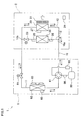
- the air conditioner 1 of the embodiment includes an indoor unit 2 that is installed in a room, an outdoor unit 6 that is installed out of the room, and a remote controller 9 (see FIG. 5 ).
- the indoor unit 2 includes an indoor heat exchanger 20 disposed to oppose to an indoor fan 21, a radiation panel 30, an indoor motor-operated valve 23, and an indoor temperature sensor 24 that detects an indoor temperature.
- the outdoor unit 6 includes a compressor 60, a four-way valve 61, an outdoor heat exchanger 62, an outdoor fan 63 that is disposed near the outdoor heat exchanger 62, and an outdoor motor-operated valve 64 (a decompression structure).
- the air conditioner 1 includes a refrigerant circuit 10 that connects the indoor unit 2 and the outdoor unit 6 to each other.
- the refrigerant circuit 10 includes a principal channel 11 in which the outdoor motor-operated valve 64, the outdoor heat exchanger 62, and the compressor 60 are provided in this order.
- An intake-side pipe fitting and a discharge-side pipe fitting of the compressor 60 are connected to the four-way valve 61.
- a branching section 10a is provided in a portion that becomes a downstream side of the compressor 60 in the principal channel 11 during a heating operation (as described later, when a refrigerant is flowing in a direction indicated by a solid-line arrow in FIG.
- the refrigerant circuit 10 also includes a first channel 12 and a second channel 13.
- the first channel 12 connects the branching section 10a and the merging section 10b to each other, and the indoor heat exchanger 20 is provided in the first channel 12.
- the second channel 13 is connected in parallel with the first channel 12 between the branching section 10a and merging section 10b, and the radiation panel 30 is provided in the second channel 13.
- An indoor motor-operated valve (valve structure) 23 is provided between the radiation panel 30 and the merging section 10b in the second channel 13.
- a panel incoming temperature sensor 25 and a panel outgoing temperature sensor 26 are attached to both sides of the radiation panel 30 in the second channel 13. More specifically, the panel incoming temperature sensor 25 is provided in a pipe fitting and is on the upstream side of a radiator 35, which will be described later, (see FIG. 4 ) of the radiation panel 30 during the heating operation.
- the panel outgoing temperature sensor 26 is provided in the pipe fitting and is on the downstream side of the radiator 35 of the radiation panel 30 and upstream side of the indoor motor-operated valve 23, during the heating operation.
- an accumulator 65 is interposed between an intake side of the compressor 60 and the four-way valve 61, and a discharge temperature sensor 66 is attached between a discharge side of the compressor 60 and the four-way valve 61.
- An outdoor heat exchanger temperature sensor 68 is attached to the outdoor heat exchanger 62.
- the indoor heat exchanger 20 includes the pipe fitting, which constitutes a part of the refrigerant circuit 10, and an indoor heat exchanger temperature sensor 27 is attached to the indoor heat exchanger 20.
- the indoor heat exchanger 20 is disposed on a windward side of the indoor fan 21. Air heated or cooled by heat exchange with the indoor heat exchanger 20 is blown as warm wind or cool wind into the room by the indoor fan 21, thereby performing warm-air heating or cooling.
- the radiation panel 30 is disposed on a surface side of the indoor unit 2, and includes a panel pipe fitting 36 which is a pipe fitting constituting a part of the refrigerant circuit 10. Heat of the refrigerant flowing in the panel pipe fitting 36 is radiated into the room to perform radiation heating.
- the indoor motor-operated valve 23 is provided in order to adjust a flow rate of the refrigerant supplied to the radiation panel 30. Controlling opening and closing of the indoor motor-operated valve 23 enables switching over between a state where the refrigerant flows in the panel pipe fitting 36 of the radiation panel 30 and a state where the refrigerant does not flow in the panel pipe fitting 36 of the radiation panel 30.
- the air conditioner 1 of the embodiment is capable of performing a cooling operation, a warm-air heating operation, and a radiation heating operation.
- the cooling operation is an operation which performs cooling by causing the refrigerant to flow not in the radiation panel 30, but in the indoor heat exchanger 20
- the warm-air heating operation is an operation which performs warm-air heating by causing the refrigerant to flow not in the radiation panel 30, but in the indoor heat exchanger 20.
- the radiation heating operation is an operation which performs radiation heating by causing the refrigerant to flow in the radiation panel 30, while performing warm-air heating by causing the refrigerant to flow in the indoor heat exchanger 20.
- FIG. 1 A flow of the refrigerant in the refrigerant circuit 10 during each operation will be described with reference to Figs. 1 and 2 .
- the indoor motor-operated valve 23 is closed, and the four-way valve 61 is switched to a state indicated by a broken line in FIG. 1 . Therefore, as indicated by a broken-line arrow in FIG. 1 , the high-temperature, high-pressure refrigerant discharged from the compressor 60 flows in the outdoor heat exchanger 62 through the four-way valve 61.
- the refrigerant condensed by the outdoor heat exchanger 62 flows in the indoor heat exchanger 20 after being decompressed by the outdoor motor-operated valve 64.
- the refrigerant vaporized by the indoor heat exchanger 20 flows in the compressor 60 through the four-way valve 61 and accumulator 65. Note that, with the indoor motor-operated valve 23 being closed, the refrigerant decompressed by the outdoor motor-operated valve 64 is kept from flowing towards the radiation panel 30 beyond the indoor motor-operated valve 23 in the second channel 13.
- the indoor motor-operated valve 23 is closed, and the four-way valve 61 is switched to the state indicated by the solid line in FIG. 1 . Therefore, as indicated by the solid-line arrow in FIG. 1 , the high-temperature, high-pressure refrigerant discharged from the compressor 60 flows in the indoor heat exchanger 20 through the four-way valve 61.
- the refrigerant condensed by the indoor heat exchanger 20 flows in the outdoor heat exchanger 62 after being decompressed by the outdoor motor-operated valve 64.
- the refrigerant vaporized by the outdoor heat exchanger 62 flows in the compressor 60 through the four-way valve 61 and accumulator 65.
- the refrigerant discharged from the compressor 60 does not flow onto the side of the merging section 10b beyond the indoor motor-operated valve 23 in the second channel 13. That is, in the second channel 13, the refrigerant is accumulated on the upstream side of the indoor motor-operated valve 23.
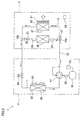
- the indoor motor-operated valve 23 is opened, and the four-way valve 61 is switched to a state indicated by a solid line in FIG. 2 . Therefore, as indicated by a solid-line arrow in FIG. 2 , the high-temperature, high-pressure refrigerant discharged from the compressor 60 flows in the indoor heat exchanger 20 and radiation panel 30 through the four-way valve 61.
- the refrigerant condensed by the indoor heat exchanger 20 and radiation panel 30 flows in the outdoor heat exchanger 62 after being decompressed by the outdoor motor-operated valve 64.
- the refrigerant vaporized by the outdoor heat exchanger 62 flows in the compressor 60 through the four-way valve 61 and accumulator 65.
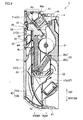
- the indoor unit 2 of the embodiment has a rectangular solid shape as a whole, and is installed near a floor surface in the room.
- the indoor unit 2 is attached to a wall surface while floating from the floor surface by about 10 cm.
- a direction in which the indoor unit 2 projects from the attached wall is referred to as a "front”, and the opposite direction is referred to as a "rear”.
- a right-left direction in FIG. 3 is simply referred to as a "horizontal direction”
- an up-down direction is simply referred to as a "vertical direction”.
- the indoor unit 2 mainly includes a casing 4, internal devices, such as the indoor fan 21, the indoor heat exchanger 20, an outlet unit 46, and an electric component unit 47, which are accommodated in the casing 4, and a front grill 42.
- the casing 4 includes a principal inlet 4a that is formed in a lower wall of the casing 4 and auxiliary inlets 4b and 4c that are formed in a front wall of the casing 4.
- An outlet 4d is formed in an upper wall of the casing 4.
- the indoor heat exchanger 20 heats or cools the drawn air to perform conditioning. Then the post-conditioning air is blown from the outlet 4d and returned to the room.
- the casing 4 includes a body frame 41, an outlet cover 51, the radiation panel 30, and an opening-closing panel 52.
- the outlet cover 51 includes a front panel section 51a
- the radiation panel 30 includes a radiation plate 31.
- the front panel section 51a of the outlet cover 51, the radiation plate 31 of the radiation panel 30, and the opening-closing panel 52 are disposed so as to be flush with one another in a front surface of the casing 4, and the front panel section 51a, the radiation plate 31, and the opening-closing panel 52 constitute a front panel 5.
- a power button 48 and an emission display section 49 that indicates an operation status are provided in an upper right end portion of the front panel 5, namely, a right end portion of the front panel section 51a of the outlet cover 51.
- the body frame 41 is one that is attached to a wall surface, and the body frame 41 supports various internal devices described above.
- the front grill 42, the outlet cover 51, the radiation panel 30, and the opening-closing panel 52 are attached to the front surface of the body frame 41 while the body frame 41 supports the internal devices.
- the outlet cover 51 is attached to an upper end portion of the body frame 41, and the outlet 4d that is of a horizontally long rectangular opening is formed on the upper wall of the outlet cover 51.
- the radiation panel 30 is attached below the outlet cover 51, and the opening-closing panel 52 is attached below the radiation panel 30.
- the principal inlet 4a that is the horizontally long opening is formed between a lower front end of the body frame 41 and a lower end of the opening-closing panel 52.
- the indoor fan 21 is disposed slightly above a central portion in a height direction of the casing 4 such that an axial direction of the indoor fan 21 is aligned with the horizontal direction.
- the indoor fan 21 draws the air from the lower front and flows the air to the upper rear.
- the indoor heat exchanger 20 is disposed in substantially parallel with the front panel 5.
- the indoor heat exchanger 20 includes a front heat exchanger 20a that is opposed to the rear surface of the front panel 5 and a rear heat exchanger 20b that is upwardly inclined toward the rear surface from a vicinity of the lower end portion of the front heat exchanger 20a.
- the front heat exchanger 20a is disposed in front of the indoor fan 21, and its upper half is opposed to the indoor fan 21.
- the rear heat exchanger 20b is disposed below the indoor fan 21 and is opposed to the indoor fan 21. That is, the indoor heat exchanger 20 as a whole has a substantially V-shape, and is disposed in such a manner as to oppose to the front and lower side of the indoor fan 21.
- a horizontally extending drain pan 22 is disposed below the indoor heat exchanger 20. Further, below the drain pan 22 is arranged an electric component unit 47.
- the outlet unit 46 is disposed above the indoor fan 21, and guides the air blown from the indoor fan 21 to the outlet 4d formed in the upper wall of the casing 4.
- the outlet unit 46 has a horizontal flap 46a disposed nearby the outlet 4d.
- the horizontal flap 46a changes the direction of an air flow from the outlet 4d relative to the vertical direction, and open or closes the outlet 4d.
- the front grill 42 is attached to the body frame 41 so as to cover the body frame 41 to which such internal devices as the indoor heat exchanger 20, the indoor fan 21, the outlet unit 46, and the electric component unit 47 are attached. More specifically, the front grill 42 is attached to the body frame 41 so as to cover a range from the substantially central portion in the vertical direction of the front heat exchanger 20a to the lower end of the body frame 41.
- the front grill 42 includes a filter retaining section 42a and an inlet grill 42b disposed in the principal inlet 4a.
- the lower filter 43 held by the filter retaining section 42a extends downward from substantially the central portion of the front heat exchanger 20a relative to the vertical direction, and its lower end portion is tilted in a direction obliquely backside.
- the lower end of the lower filter 43 is positioned nearby the rear end of the principal inlet 4a.
- the upper filter 44 extends upwards from the substantially central portion of the front heat exchanger 20a relative to the vertical direction.
- the outlet cover 51 covers the outlet unit 46. As described above, the outlet 4d is formed in the upper wall of the outlet cover 51.
- the front panel section 51a is provided in the front surface of the outlet cover 51.
- the front panel section 51a has the horizontally long rectangular shape.
- the radiation panel 30 has the horizontally long, substantially rectangular shape.
- the radiation panel 30 mainly includes an aluminum radiation plate 31 and a resin heat-insulating cover 32 attached to the rear surface of the radiation plate 31.
- the radiation plate 31 is positioned below the front panel section 51a of the outlet cover 51.
- the panel pipe fitting 36 that is of the part of the pipe fitting constituting the refrigerant circuit 10 is attached to the rear surface of the radiation plate 31.
- the portion of the radiation panel 30 where the radiation plate 31 and the panel pipe fitting 36 are in contact with each other, are the portions serving as the radiator 35.
- the opening-closing panel 52 is detachably attached to the lower portion of the radiation plate 31 of the radiation panel 30.
- the opening-closing panel 52 has the horizontally long rectangular shape. As illustrated in FIG. 4 , the vertical position at the upper end of the opening-closing panel 52 has the substantially same level as the upper end of the front grill 42. As described above, the lower end of the opening-closing panel 52 constitutes the part of the principal inlet 4a. Accordingly, the front grill 42 is exposed by detaching the opening-closing panel 52, so that the lower filter 43 and upper filter 44, which are attached to the filter retaining section 42a of the front grill 42, can be detached.
- a user is able to start or stop the operation of the air conditioner 1, set the operation mode, set the target indoor temperature (indoor setting temperature), or set the blowing air quantity, or the like.
- the controller 7 for controlling the air conditioner 1 is described with reference to FIG. 5 .
- the controller 7 has a storage 70, an indoor motor-operated valve controller 72, an abnormality detector 73, an indoor fan controller 74, a compressor controller 75, and an outdoor motor-operated valve controller 76.
- the storage 70 stores various operation settings related to the air conditioner 1, a control program, a data table necessary for running the control program, or the like.
- the operation settings include user-setting set by a user operating the remote controller 9, such as target indoor temperature (indoor setting temperature), and a presetting which is set in advance in the air conditioner 1.
- the target temperature range of the radiation panel 30 is set to a predetermined temperature range (e.g., 50 to 55°C).
- the target temperature range of the radiation panel 30 however may be set by operating the remote controller 9.
- the indoor motor-operated valve controller 72 controls the opening degree of the indoor motor-operated valve 23. During the cooling operation or the warm-air heating operation, the indoor motor-operated valve controller 72 closes the indoor motor-operated valve 23. Further, during the radiation heating operation, the indoor motor-operated valve controller 72 controls the opening degree of the indoor motor-operated valve 23 based on the temperature of the radiation panel 30. Specifically, a surface temperature (predicted value) of the radiation panel 30 is calculated based on a calculated value of temperatures detected by the panel incoming temperature sensor 25 and the panel outgoing temperature sensor 26.
- the opening degree of the indoor motor-operated valve 23 is controlled so that this surface temperature of the radiation panel 30 (hereinafter, simply referred to as radiation panel temperature) is within a panel target temperature range (e.g. 50 to 55°C). Note that when the value detected by the panel incoming temperature sensor 25 is a predetermined value (e.g. , 80°C) or more, the indoor motor-operated valve 23 is closed.
- the abnormality detector 73 detects occurrence of an abnormality in the indoor motor-operated valve 23, based on the temperature of the radiation panel 30. That is, during the cooling operation and during the warm-air heating operation, the abnormality detector 73 detects occurrence of an abnormality in the indoor motor-operated valve 23, if the refrigerant flows out of the indoor motor-operated valve 23 which is supposed to be closed and flows in the panel pipe fitting 36 of the radiation panel 30. Further, during the radiation heating operation, occurrence of an abnormality in the indoor motor-operated valve 23 is detected when the indoor motor-operated valve 23 is completely closed, and the refrigerant does not flow in the panel pipe fitting 36 of the radiation panel 30.
- the abnormality detector 73 detects occurrence of an abnormality in the indoor motor-operated valve 23, based on a temperature (hereinafter, simply referred to as indoor temperature Ta) detected by the indoor temperature sensor 24, a temperature (hereinafter, simply referred to as panel pipe fitting temperature TP) detected by the panel outgoing temperature sensor 26, and a temperature (hereinafter, simply referred to as indoor heat exchanger temperature Te) detected by the indoor heat exchanger temperature sensor 27. Further, during the warm-air heating operation and during the radiation heating operation, occurrence of an abnormality in the indoor motor-operated valve 23 is detected based on the panel pipe fitting temperature TP and the indoor heat exchanger temperature Te.
- the abnormality in the indoor motor-operated valve 23 is detected only in cases where the temperature of the refrigerant flowing out of the outdoor motor-operated valve 64 is sufficiently low and where such a refrigerant, when flowing into the pipe fitting of the radiation panel 30, may cause dew condensation on the radiation panel 30. Therefore, an abnormality in the indoor motor-operated valve 23 is detected by the abnormality detector 73 on condition that the following (Formula 2) and (Formula 3) are satisfied, in addition to (Formula 1). TP ⁇ 32 ⁇ °C Te ⁇ 32 ⁇ °C
- the outdoor unit 6 is a multi-connectable outdoor unit which is connectable with a plurality of indoor units
- the pressure (low pressure) in the indoor heat exchanger 20 may not sufficiently drop.
- the indoor temperature Ta, the panel pipe fitting temperature TP, and the indoor heat exchanger temperature Te are substantially the same temperature in such a case, the above (Formula 1) may be satisfied even though no abnormality takes place in the indoor motor-operated valve 23.
- the following (Formula 4) is added to the above (Formula 1) to (Formula 3) as a condition for the abnormality detector 73 to detect that the indoor motor-operated valve 23 is abnormal.
- Ta - Te ⁇ 5 deg .
- an abnormality detectable area of the indoor motor-operated valve 23 is only an area (I) shown in FIG. 6 . That is, an abnormality in the indoor motor-operated valve 23 is not detected in an area (an area indicated by (II) in the figure) where the indoor heat exchanger temperature Te is higher than the indoor temperature Ta (i.e., Ta-Te ⁇ 0 deg.) and where detection of abnormality in the indoor motor-operated valve 23 is not necessary, and in an area (area indicated by (III) in the figure) where the difference between the indoor temperature Ta and the indoor heat exchanger temperature Te is relatively small (i.e., 0 deg. ⁇ Ta-Te ⁇ 5 deg.) and misdetection of an abnormality in the indoor motor-operated valve 23 may take place.
- the abnormality detector 73 detects that the indoor motor-operated valve 23 is abnormal.
- the abnormality occurs in the indoor motor-operated valve 23 and the refrigerant flows out of the indoor motor-operated valve 23 which is supposed to be closed, the high-temperature refrigerant having flown from the branching section 10a into the second channel 13 flows out of the second channel 13 via the pipe fitting of the radiation panel 30 and the indoor motor-operated valve 23. Therefore, the panel pipe fitting temperature TP detected by the panel outgoing temperature sensor 26 increases and becomes equal to or higher than the indoor heat exchanger temperature Te detected by the indoor heat exchanger temperature sensor 27 provided in the indoor heat exchanger 20. That is, an abnormality in the indoor motor-operated valve 23 is detected by the abnormality detector 73 on condition that the following (Formula 5) is satisfied. Te - TP ⁇ 0 deg .
- an abnormality in the indoor motor-operated valve 23 is detected only in cases where the temperature of the refrigerant discharged from the compressor 60 is relatively high and where the radiation panel 30 has a high temperature of a certain extent as the refrigerant passes through the pipe fitting in the radiation panel 30. Therefore, an abnormality in the indoor motor-operated valve 23 is detected by the abnormality detector 73 on condition that the following (Formula 6) and (Formula 7) are satisfied, in addition to (Formula 5).
- an abnormality detectable area of the indoor motor-operated valve 23 is only an area (an area indicated by (I) in the figure) shown in FIG. 7 , where the panel temperature TPO is 40°C or higher and where the indoor heat exchanger temperature Te is 43°C or higher.
- an abnormality in the indoor motor-operated valve 23 is not detected in an area (an area indicated by (II) in the figure) which does not possibly occur in an actual operation, in which area the panel temperature TPO is 40°C or higher and the indoor heat exchanger temperature Te is lower than 43°C, or in an area (an area indicated by (III) in the figure) where the panel temperature TPO is lower than 40°C, in which case if an abnormality is to be detected, there would be a chance of misdetection of an abnormality in the indoor motor-operated valve 23.
- the abnormality detector 73 detects that the indoor motor-operated valve 23 is abnormal.
- the indoor temperature is 10°C
- the indoor heat exchanger temperature is 55°C
- the difference between the indoor heat exchanger temperature Te and the panel pipe fitting temperature TP is 35 deg.
- an abnormality in the indoor motor-operated valve 23 is not detected if the temperature of the radiation panel 30 shows a certain increase even though the indoor motor-operated valve 23 is closed.
- An abnormality in the indoor motor-operated valve 23 is detected only if there seems to be no increase in the temperature of the radiation panel 30. Therefore, an abnormality in the indoor motor-operated valve 23 is detected by the abnormality detector 73 on condition that the following (Formula 9) and (Formula 10) are satisfied, in addition to (Formula 8).
- an abnormality detectable area of the indoor motor-operated valve 23 is only an area (I) shown in FIG. 8 .
- an abnormality in the indoor motor-operated valve 23 is not detected in an area (an area indicated by (II) in the figure) which does not possibly occur in an actual operation, in which area the panel temperature TP0 is higher than the indoor heat exchanger temperature Te (i.e., Te - TPO ⁇ 0 deg.), or in an area (an area indicated by (III) in the figure) where the difference between the indoor heat exchanger temperature Te and the panel temperature TPO is relatively small (i.e., 0 deg. ⁇ Te - TPO ⁇ 35 deg.) and where an abnormality in the indoor motor-operated valve 23 is not detectable.
- the abnormality detector 73 detects that the indoor motor-operated valve 23 is abnormal.
- the indoor fan controller 74 controls the rotational frequency of the indoor fan 21 according to the operation mode, the indoor setting temperature, the blowing air quantity set by the remote controller 9, and the indoor temperature detected by the indoor temperature sensor 24.
- the compressor controller 75 controls the operation frequency of the compressor 60, based on the indoor temperature, the indoor setting temperature, the heat exchanger temperature detected by the indoor heat exchanger temperature sensor 27, and the like.
- the outdoor motor-operated valve controller 76 controls the opening degree of the outdoor motor-operated valve 64. More specifically, the outdoor motor-operated valve controller 76 controls the opening degree of the outdoor motor-operated valve 64 so that the temperature detected by the discharge temperature sensor 66 becomes an optimal temperature in the operation status.
- the optimal temperature is determined based on a calculated value using the indoor heat exchanger temperature and an outdoor heat exchanger temperature.
- the following describes the steps of an abnormality detecting process executed by the abnormality detector 73 for detecting an abnormality in the indoor motor-operated valve 23.
- step S11 the indoor temperature Ta detected by the indoor temperature sensor 24, the panel pipe fitting temperature TP detected by the panel outgoing temperature sensor 26, and the Te detected by the indoor heat exchanger temperature sensor 27 are first obtained (step S11).
- step S12 there is determined whether or not the difference between the indoor temperature Ta and the indoor heat exchanger temperature Te is 5 deg. or more (step S12).
- step S12 NO
- step S12 NO
- step S12 when the difference between the indoor temperature Ta and the indoor heat exchanger temperature Te is at least 5 deg. (step S12: YES), there is determined whether or not the difference between the panel pipe fitting temperature TP and the indoor heat exchanger temperature Te is at most 0 deg. (step S13).
- step S13 NO
- step S14 there is determined whether the panel pipe fitting temperature TP is at most 32°C, and there is determined in step S15 whether the indoor heat exchanger temperature Te is at most 32°C.
- step S14: NO the panel pipe fitting temperature TP is determined as to be higher than the 32°C in step S14
- step S15 the indoor heat exchanger temperature Te is determined as to be higher than 32°C in step S15
- step S16 when the panel pipe fitting temperature TP is determined as to be 32°C or lower in step S14 (step S14: YES), or when the indoor heat exchanger temperature Te is determined as to be 32°C or lower in step S15 (step S15: YES), occurrence of an abnormality in the indoor motor-operated valve 23 is detected (step S16).
- step S21 the panel pipe fitting temperature TP detected by the panel outgoing temperature sensor 26, the Te detected by the indoor heat exchanger temperature sensor 27 are first obtained (step S21).
- step S22 there is determined whether the difference between the indoor heat exchanger temperature Te and the panel pipe fitting temperature TP is at most 0 deg.
- step S22: NO it is considered that the indoor motor-operated valve 23 is properly closed, and there is no refrigerant flowing out. Therefore, the process does not proceed to the next step and returns to step S21.
- step S22 when the difference between the indoor heat exchanger temperature Te and the panel pipe fitting temperature TP is at most 0 deg. (step S22: YES), it is considered that the refrigerant is flowing out of the indoor motor-operated valve 23 which is supposed to be closed.
- step S23 there is determined whether the panel pipe fitting temperature TP is 43°C or higher in step S23, and there is determined whether the indoor heat exchanger temperature Te is 43°C or higher in step S24.
- step S23: NO When the panel pipe fitting temperature TP is determined as to be lower than 43°C in step S23 (step S23: NO), or when the indoor heat exchanger temperature Te is determined as to be lower than 43°C in step S24 (step S24: NO), it is considered that the temperature of the radiation panel 30 will not increase so much (that detection of an abnormality in the indoor motor-operated valve 23 is necessary). Therefore, the process does not proceed to the next step and returns to step S21.
- step S23 when the panel pipe fitting temperature TP is determined as to be 43°C or higher in step S23 (step S23: YES), or when the indoor heat exchanger temperature Te is determined as to be 43°C or higher in step S24 (step S24: YES), occurrence of an abnormality in the indoor motor-operated valve 23 is detected (step S25).
- step S31 the panel pipe fitting temperature TP detected by the panel outgoing temperature sensor 26, the Te detected by the indoor heat exchanger temperature sensor 27 are first obtained (step S31).
- step S32 there is determined whether the difference between the indoor heat exchanger temperature Te and the panel pipe fitting temperature TP is 35 deg. or greater (step S32).
- step S22: NO it is considered that the indoor motor-operated valve 23 is opened. Therefore, the process does not proceed to the next step and returns to step S31.
- step S32: YES when the difference between the indoor heat exchanger temperature Te and the panel pipe fitting temperature TP is 35 deg. or greater (step S32: YES), it is considered that the indoor motor-operated valve 23 which is supposed to be opened is closed.
- step S33: NO there is determined whether the panel pipe fitting temperature TP is at most 60°C in step S33, and there is determined whether the indoor heat exchanger temperature Te is at most 60°C or lower in step S34.
- step S33 NO
- step S34 NO
- step S33 when the panel pipe fitting temperature TP is determined as to be 60°C or lower in step S33 (step S33: YES), or when the indoor heat exchanger temperature Te is determined as to be 60°C or lower in step S34 (step S34: YES), occurrence of an abnormality in the indoor motor-operated valve 23 is detected (step S35).
- the occurrence of an abnormality in the indoor motor-operated valve 23 is detected in the abnormality detecting process, for example, the occurrence of an abnormality is reported to the user by means of indication on the emission display section 49 or the like.
- the controller 7 has the abnormality detector 73 which detects occurrence of an abnormality in the indoor motor-operated valve 23 which is configured to switch over between a state where the refrigerant flows in the panel pipe fitting 36 of the radiation panel 30 and a state where the refrigerant does not flow in the panel pipe fitting 36 of the radiation panel 30. Therefore, it is possible to detect occurrence of an abnormality in the indoor motor-operated valve 23 by the abnormality detector 73. This restrains dew condensation on the radiation panel 30 during the cooling operation, and an abnormality in the surface temperature of the radiation panel 30 during the indoor motor-operated valve 23 during the warm-air heating operation and radiation heating operation, which are attributed to the abnormality in the indoor motor-operated valve 23.
- the refrigerant circuit 10 has: the principal channel 11 in which the outdoor motor-operated valve 64, the outdoor heat exchanger 62, and the compressor 60 are provided in this order; the first channel 12 having the indoor heat exchanger 20, which, during the heating operation, connects the branching section 10a provided on the downstream side of the compressor 60 in the principal channel 11 with the merging section 10b provided on the upstream side of the outdoor motor-operated valve 64; and a second channel 13 having the radiation panel 30, which connects the branching section 10a and the merging section 10b in parallel with the first channel 12.
- the indoor motor-operated valve 23 is provided between the radiation panel 30 and the merging section 10b in the refrigerant circuit 10. Therefore, it is possible to detect occurrence of an abnormality in the indoor motor-operated valve 23 in the air conditioner 1 in which the first channel 12 having the indoor heat exchanger 20 and the second channel 13 having the radiation panel 30 are connected in parallel with each other.
- the abnormality detector 73 detects occurrence of an abnormality in the indoor motor-operated valve 23, based on the panel pipe fitting temperature TP detected by the panel outgoing temperature sensor 26 between the radiator 35 of the radiation panel 30 and the indoor motor-operated valve 23, and the indoor heat exchanger temperature Te detected by the indoor heat exchanger temperature sensor 27 provided to the indoor heat exchanger 20. Therefore, it is possible to detect the open/close state of the indoor motor-operated valve 23 by comparing the panel pipe fitting temperature TP with the indoor heat exchanger temperature Te.
- the abnormality detector 73 detects occurrence of an abnormality in the indoor motor-operated valve 23 only when the difference between the indoor temperature Ta detected by the indoor temperature sensor 24 and the indoor heat exchanger temperature Te is 5 deg. or greater. Excluding the cases where the difference between the indoor temperature Ta and the indoor heat exchanger temperature Te is small, misdetection of an abnormality in the indoor motor-operated valve 23 is restrained.
- the refrigerant circuit 10 that connects the indoor unit 2 and the outdoor unit 6 to each other includes the second channel 13 that is connected in parallel with the first channel 12 in which the indoor heat exchanger 20 is provided, and the radiation panel 30 is provided in the second channel 13.
- the indoor heat exchanger 20 and the radiation panel 30 may be connected in series with each other.
- a refrigerant circuit 110 of an air conditioner 101 includes a circular principal channel 111 in which the outdoor motor-operated valve 64, the outdoor heat exchanger 62, the compressor 60, the radiation panel 30, and the indoor heat exchanger 20 are connected in this order.
- the discharge-side pipe fitting and intake-side pipe fitting of the compressor 60 are connected to the four-way valve 61.
- Branching sections 101a and 101b are respectively provided on both sides of the radiation panel 30, and both ends of a branching channel 112 are connected to the branching sections 101a and 101b.
- the branching section 101a is located between the indoor heat exchanger 20 and the radiation panel 30, and the branching section 101b is located on the opposite side to the branching section 101a with respect to the radiation panel 30. Further, the branching section 101a is provided with a three-way valve 123.
- a panel incoming temperature sensor 25 Between the branching section 101b and the radiator 35 of the radiation panel 30 is a panel incoming temperature sensor 25. Between the branching section 101a and the radiator 35 of the radiation panel 30 is a panel outgoing temperature sensor 26.
- the four-way valve 61 is switched to a state indicated by a broken line in FIG. 12 during the cooling operation. Further, the three-way valve 123 is switched to a state in which the refrigerant from the indoor heat exchanger 20 flows in the branching channel 112 but not in the radiation panel 30. Therefore, as indicated by a broken-line arrow in FIG. 12 , the high-temperature, high-pressure refrigerant discharged from the compressor 60 flows in the outdoor heat exchanger 62 through the four-way valve 61. The refrigerant condensed by the outdoor heat exchanger 62 flows in the indoor heat exchanger 20 after being decompressed by the outdoor motor-operated valve 64. The refrigerant vaporized by the indoor heat exchanger 20 flows in the compressor 60 through the branching channel 112, four-way valve 61, and accumulator 65.
- the four-way valve 61 is switched to a state indicated by a solid line in FIG. 12 . Further, the three-way valve 123 is switched to a state in which the refrigerant ejected from the compressor 60 flows in the branching channel 112 but not in the radiation panel 30. Therefore, the high-temperature, high-pressure refrigerant discharged from the compressor 60 flows into the indoor heat exchanger 20, through the four-way valve 61 and the branching channel 112, as shown by the solid-line arrow in FIG. 12 .
- the refrigerant condensed by the indoor heat exchanger 20 flows in the outdoor heat exchanger 62 after being decompressed by the outdoor motor-operated valve 64.
- the refrigerant vaporized by the outdoor heat exchanger 62 flows in the compressor 60 through the four-way valve 61 and accumulator 65.
- the four-way valve 61 is switched to the state indicated by a solid line in FIG. 12 . Further, the three-way valve 123 is switched to a state in which the refrigerant discharged from the compressor 60 flows in the radiation panel 30 and in the branching channel 112. Therefore, the high-temperature, high-pressure refrigerant discharged from the compressor 60 flows into the radiation panel 30 through the four-way valve 61, and then flows into the indoor heat exchanger 20, as shown by the bold-line arrow in FIG. 12 .
- the refrigerant condensed by the radiation panel 30 and indoor heat exchanger 20 flows in the outdoor heat exchanger 62 after being decompressed by the outdoor motor-operated valve 64.
- the refrigerant vaporized by the outdoor heat exchanger 62 flows in the compressor 60 through the four-way valve 61 and accumulator 65.
- the abnormality detector 73 of the controller 7 detects occurrence of an abnormality in the three-way valve 123 configured to switch over between a state where the refrigerant flows in the panel pipe fitting 36 of the radiation panel 30 and a state where the refrigerant does not flow in the panel pipe fitting 36 of the radiation panel 30, as in the case of the embodiment described above.
- the outdoor motor-operated valve 64, the outdoor heat exchanger 62, the compressor 60, the radiation panel 30, and the indoor heat exchanger 20 are connected in this order in the annular principal channel 111 of the refrigerant circuit 110; however, the present invention is not limited to this. That is, the positions of the radiation panel 30 and the indoor heat exchanger 20 may be other way around; i.e., the outdoor motor-operated valve 64, the outdoor heat exchanger 62, the compressor 60, the indoor heat exchanger 20, and the radiation panel 30 may be connected in this order.
- the both ends of the branching channel 112 are connected to the branching sections provided to both ends of the radiation panel 30.0 Further, the three-way valve 123 configured to switch over between a state where the refrigerant flows in the panel pipe fitting 36 of the radiation panel 30 and a state where the refrigerant does not flow in the panel pipe fitting 36 of the radiation panel 30 may be provided to the branching section positioned on the opposite side of the indoor heat exchanger 20 over the radiation panel 30.
- the indoor motor-operated valve 23 is provided between the radiation panel 30 and the merging section 10b in the refrigerant circuit 10; however, the present invention is not limited to this.
- the three-way valve may be provided to the merging section 10b, and this three-way valve may be used as the indoor motor-operated valve 23.
- the abnormality detector 73 detects occurrence of an abnormality in the indoor motor-operated valve 23 based on the panel pipe fitting temperature TP detected by the panel outgoing temperature sensor 26 provided between the radiator 35 of the radiation panel 30 and the indoor motor-operated valve 23 and the indoor heat exchanger temperature Te; however, the present invention is not limited to this. That is, for example, it is possible to configure the abnormality detector 73 so as to detect occurrence of an abnormality in the indoor motor-operated valve 23 based on the temperature detected by the panel incoming temperature sensor 25 provided on the opposite side to the indoor motor-operated valve 23 over the radiator 35 of the radiation panel 30 and the indoor heat exchanger temperature Te.
- the abnormality detector 73 during the cooling operation detects occurrence of an abnormality in the indoor motor-operated valve 23, when the difference between the indoor temperature Ta and the indoor heat exchanger temperature Te is a predetermined value or greater; however, the present invention is not limited to this. Misdetection is prevented by having the abnormality detector 73 detect an abnormality in the indoor motor-operated valve 23 when the pressure (low pressure) in the indoor heat exchanger 20 is at a predetermined value or lower. Therefore, it is possible to configure the abnormality detector 73 so as to detect occurrence of an abnormality in the indoor motor-operated valve 23, when the difference between the indoor temperature Ta and the panel pipe fitting temperature TP is a predetermined difference or greater.
- the abnormality detector 73 during the radiation heating operation detects occurrence of an abnormality in the indoor motor-operated valve 23 when the indoor motor-operated valve 23 is completely closed; however, the present invention is not limited to this. That is, occurrence of an abnormality in the indoor motor-operated valve 23 may be detected, not only in cases where the indoor motor-operated valve 23 is completely closed, but also in cases where the opening degree of the indoor motor-operated valve 23 falls short of a required opening degree (an opening degree to cause the surface temperature of the radiation panel 30 to fall within a panel target temperature range).
- occurrence of an abnormality in the indoor motor-operated valve 23 is detected when (Formula 1) to (Formula 4) are all satisfied during the cooling operation, when (Formula 5) to (Formula 7) are all satisfied during the warm-air heating operation, and when (Formula 8) to (Formula 10) are all satisfied during the radiation heating operation; however, the present invention is not limited to this. That is, occurrence of an abnormality in the indoor motor-operated valve 23 may be detected when at least (Formula 1) is satisfied during the cooling operation, when at least (Formula 5) is satisfied during the warm-air heating operation, and when at least (Formula 8) is satisfied during the radiation heating operation. Further, numerical values given in (Formula 1) to (Formula 8) are no more than examples, and are variable as needed.
- the present invention allows detection of an abnormality in a valve structure.
Landscapes
- Engineering & Computer Science (AREA)
- Mechanical Engineering (AREA)
- General Engineering & Computer Science (AREA)
- Chemical & Material Sciences (AREA)
- Combustion & Propulsion (AREA)
- Physics & Mathematics (AREA)
- Thermal Sciences (AREA)
- Life Sciences & Earth Sciences (AREA)
- Sustainable Development (AREA)
- Air Conditioning Control Device (AREA)
- Devices For Blowing Cold Air, Devices For Blowing Warm Air, And Means For Preventing Water Condensation In Air Conditioning Units (AREA)
Abstract

Description
- The present invention relates to an air conditioner including an indoor unit having an indoor heat exchanger and a radiation panel.
- As an air conditioner, there has been known one which is connected to an outdoor unit through a refrigerant circuit, and which includes an indoor unit having therein an indoor heat exchanger, and a radiation panel provided to a surface of the indoor unit (e.g., see PTL 1). In the refrigerant circuit of the air conditioner disclosed in
PTL 1, the indoor heat exchanger and the radiation panel are connected in parallel with each other. - [PTL 1] Japanese Unexamined Patent Publication No.
280762/1993 - In the above described air conditioner, it is possible to provide a valve structure for adjusting the flow rate of a refrigerant supplied to the radiation panel, on a downstream side of the radiation panel, during a heating operation. In this air conditioner, the valve structure is closed during a cooling operation, so that the refrigerant does not flow in the radiation panel, but flows only in the indoor heat exchanger. During a warm-air heating operation, the valve structure is closed so that the refrigerant does not flow in the radiation panel and flows only in the indoor heat exchanger. During a radiation heating operation, the valve structure is opened and the refrigerant flows both in the radiation panel and the indoor heat exchanger.
- In the above described refrigerant circuit, various problems may take place when there is an abnormality in the valve structure. For example, during the cooling operation, if the refrigerant flows out of the valve structure which is supposed to be closed, a low-temperature refrigerant flows into the pipe fitting of the radiation panel and causes dew condensation on the radiation panel. Further, during the warm-air heating operation, if the refrigerant leaks from the valve structure which is supposed to be closed, a high-temperature refrigerant passes the pipe fitting of the radiation panel causing an increase in the temperature of the radiation panel which is not supposed to increase. Further, during the radiation heating operation, if the valve structure is closed, or if the opening degree falls short of a required opening degree, the temperature of the radiation panel which is supposed to increase does not increase. These problems attributed to an abnormality in the valve structure may also take place in a similar manner, in a circuit where the indoor heat exchanger and the radiation panel are serially connected.
- In view of the above problems, an objective of the present invention is to provide an air conditioner capable of detecting occurrence of an abnormality in the valve structure.
- A first aspect of the present invention is an air conditioner, comprising a refrigerant circuit connecting an indoor unit with an outdoor unit, wherein the indoor unit has therein an indoor heat exchanger provided to oppose to a fan and a radiation panel provided on a surface of the indoor unit, and wherein the refrigerant circuit includes: a valve structure configured to perform switching over between a state where a refrigerant flows in the radiation panel and a state where the refrigerant does not flow in the radiation panel; and an abnormality detector configured to detect occurrence of an abnormality in the valve structure based on a temperature of the radiation panel.
- In this air conditioner, occurrence of an abnormality in the valve structure is detectable by the abnormality detector based on the temperature of the radiation panel. This restrains dew condensation on the radiation panel during the cooling operation and inappropriate radiation panel temperatures during the warm-air heating operation and the radiation heating operation, which are attributed to an abnormality in the valve structure.
- A second aspect of the present invention is the air conditioner of the first aspect, adapted so that the refrigerant circuit includes: a principal channel in which a decompression structure, an outdoor heat exchanger, and a compressor are provided in this order; a first channel provided with the indoor heat exchanger, which connects a branching section provided to the downstream side of the compressor in the principal channel with a merging section provided to the upstream side of the decompression structure during the heating operation; and a second channel provided with the radiation panel, which connects the branching section and the merging section with the first channel in parallel; and wherein the valve structure is provided between the radiation panel and the merging section in the refrigerant circuit.
- Note that the "the valve structure is provided between the radiation panel and the merging section in the refrigerant circuit" encompasses cases where the valve structure is provided to the merging section.
- In this air conditioner in which the first channel having the indoor heat exchanger and the second channel having the radiation panel are connected in parallel with each other, occurrence of an abnormality in the valve structure is detectable.
- A third aspect of the present invention is the air conditioner of the first or the second invention, adapted so that the abnormality detector detects occurrence of an abnormality in the valve structure, if the refrigerant flows in the radiation panel while the valve structure is in a state in which the refrigerant does not flow in the radiation panel.
- In this air conditioner, occurrence of an abnormality in the valve structure is detectable by the abnormality detector, if the refrigerant flows in the radiation panel while the valve structure is in the state where the refrigerant does not flow in the radiation panel.
- A fourth aspect of the present invention is the air conditioner of the first to the third invention, further including: an indoor heat exchanger temperature sensor provided to the indoor heat exchanger; and a panel temperature sensor provided between a radiator of the radiation panel and the valve structure, wherein the abnormality detector detects occurrence of an abnormality in the valve structure, based on a temperature detected by the panel temperature sensor and a temperature detected by the indoor heat exchanger temperature sensor.
- In this air conditioner, the open/close state of the valve structure is detectable by comparing the temperature detected by the panel temperature sensor with the temperature detected by the indoor heat exchanger temperature sensor. Thus, occurrence of an abnormality in the valve structure is detectable, if the valve structure is opened and the refrigerant flows in the radiation panel while the valve structure is supposed to be in the state where the refrigerant does not flow in the radiation panel, or if the valve structure is closed and the refrigerant does not flow in the radiation panel while the valve structure is supposed to be in the state where the refrigerant flows in the radiation panel.
- A fifth aspect of the present invention is the air conditioner of the fourth aspect, adapted so that wherein, during the cooling operation, the abnormality detector detects occurrence of an abnormality in the valve structure, when a pressure in the indoor heat exchanger is at or lower than a predetermined value.
- This air conditioner brings about the following effect. Namely, when the pressure (low pressure) in the indoor heat exchanger is not sufficiently lowered during the cooling operation, the difference between the indoor temperature and the temperature detected by the indoor heat exchanger temperature sensor is small. In such a case, the temperature detected by the panel temperature sensor and the temperature detected by the indoor heat exchanger temperature sensor are close to each other, even when the valve structure is properly closed and the refrigerant does not flow in the radiation panel. Therefore, even though there is no abnormality in the valve structure, there is a possibility of misdetection that the refrigerant is flowing in the radiation panel due to an abnormality in the valve structure. In view of this, misdetection of abnormality in the valve structure is restrained by excluding such a case.
- A sixth aspect of the present invention is the air conditioner of the fourth or the fifth invention, further including an indoor temperature sensor configured to detect an indoor temperature, wherein the abnormality detector detects occurrence of an abnormality in the valve structure, when a difference between a temperature detected by the indoor temperature sensor and a temperature detected by the indoor heat exchanger temperature sensor is a predetermined value or greater.
- In this air conditioner, misdetection of an abnormality in the valve structure is restrained by excluding cases where the difference between the temperature detected by the indoor temperature sensor and the temperature detected by the indoor heat exchanger temperature sensor is small.
- As hereinabove described, the present invention brings about the following effects.
- In the first aspect of the present invention, occurrence of an abnormality in the valve structure is detectable by the abnormality detector based on the temperature of the radiation panel. This restrains problems such as dew condensation on the radiation panel during the cooling operation and inappropriate radiation panel temperatures during the warm-air heating operation and the radiation heating operation, which are attributed to an abnormality in the valve structure.
- With the second aspect of the present invention, occurrence of an abnormality in the valve structure is detectable in an air conditioner in which the first channel having the indoor heat exchanger and the second channel having the radiation panel are connected in parallel with each other.
- In the third aspect of the present invention, occurrence of an abnormality in the valve structure is detectable by the abnormality detector, if the refrigerant flows in the radiation panel while the valve structure is in the state where the refrigerant does not flow in the radiation panel.
- In the fourth aspect of the present invention, the open/close state of the valve structure is detectable by comparing the temperature detected by the panel temperature sensor with the temperature detected by the indoor heat exchanger temperature sensor. Thus, occurrence of an abnormality in the valve structure is detectable, if the valve structure is opened and the refrigerant flows in the radiation panel while the valve structure is supposed to be in the state where the refrigerant does not flow in the radiation panel, or if the valve structure is closed and the refrigerant does not flow in the radiation panel while the valve structure is supposed to be in the state where the refrigerant flows in the radiation panel.
- The fifth aspect of the present invention brings about the following effect. Namely, when the pressure (low pressure) in the indoor heat exchanger is not sufficiently lowered during the cooling operation, the difference between the indoor temperature and the temperature detected by the indoor heat exchanger temperature sensor is small. In such a case, the temperature detected by the panel temperature sensor and the temperature detected by the indoor heat exchanger temperature sensor are close to each other, even when the valve structure is properly closed and the refrigerant does not flow in the radiation panel. Therefore, even though there is no abnormality in the valve structure, there is a possibility of misdetection that the refrigerant is flowing in the radiation panel due to an abnormality in the valve structure. In view of this, misdetection of abnormality in the valve structure is restrained by excluding such a case.
- In the sixth aspect of the present invention, misdetection of an abnormality in the valve structure is restrained by excluding cases where the difference between the temperature detected by the indoor temperature sensor and the temperature detected by the indoor heat exchanger temperature sensor is small.
-
- [
FIG. 1] FIG. 1 is a circuit diagram illustrating a schematic configuration of an air conditioner related to an embodiment of the present invention, and shows a flow of a refrigerant during a cooling operation and a warm-air heating operation. - [
FIG. 2] FIG. 2 is a circuit diagram illustrating a schematic configuration of the air conditioner related to the embodiment of the present invention, and shows a flow of the refrigerant during the radiation heating operation. - [
FIG. 3] FIG. 3 is a perspective view of an indoor unit illustrated inFIG. 1 andFIG. 2 . - [
FIG. 4] FIG. 4 is a cross sectional view of the indoor unit taken along the line IV-IV inFIG. 3 . - [
FIG. 5] FIG. 5 is a block diagram illustrating a schematic configuration of a controller controlling the air conditioner. - [
FIG. 6] FIG. 6 is a graph explaining a condition for detecting an abnormality by an abnormality detector illustrated inFIG. 5 , during the cooling operation, taking into account prevention of misdetection. - [
FIG. 7] FIG. 7 is a graph explaining a condition for detecting an abnormality by the abnormality detector illustrated inFIG. 5 , during the warm-air heating operation. - [
FIG. 8] FIG. 8 is a graph explaining a condition for detecting an abnormality by the abnormality detector illustrated inFIG. 5 , during the radiation heating operation. - [
FIG. 9] FIG. 9 is a flowchart showing steps of an abnormality detecting process executed by the abnormality detector illustrated inFIG. 5 during the cooling operation. - [
FIG. 10] FIG. 10 is a flowchart showing steps of an abnormality detecting process executed by the abnormality detector illustrated inFIG. 5 during the warm-air heating operation. - [
FIG. 11] FIG. 11 is a flowchart showing steps of an abnormality detecting process executed by the abnormality detector illustrated inFIG. 5 during the radiation heating operation. - [
FIG. 12] FIG. 12 is a circuit diagram illustrating a schematic configuration of an air conditioner related to a modification of the embodiment. - Hereinafter, an
air conditioner 1 according to an embodiment of the present invention will be described. - As illustrated in
Figs. 1 and2 , theair conditioner 1 of the embodiment includes anindoor unit 2 that is installed in a room, anoutdoor unit 6 that is installed out of the room, and a remote controller 9 (seeFIG. 5 ). Theindoor unit 2 includes anindoor heat exchanger 20 disposed to oppose to anindoor fan 21, aradiation panel 30, an indoor motor-operatedvalve 23, and anindoor temperature sensor 24 that detects an indoor temperature. Theoutdoor unit 6 includes acompressor 60, a four-way valve 61, anoutdoor heat exchanger 62, anoutdoor fan 63 that is disposed near theoutdoor heat exchanger 62, and an outdoor motor-operated valve 64 (a decompression structure). - The
air conditioner 1 includes arefrigerant circuit 10 that connects theindoor unit 2 and theoutdoor unit 6 to each other. Therefrigerant circuit 10 includes aprincipal channel 11 in which the outdoor motor-operatedvalve 64, theoutdoor heat exchanger 62, and thecompressor 60 are provided in this order. An intake-side pipe fitting and a discharge-side pipe fitting of thecompressor 60 are connected to the four-way valve 61. A branchingsection 10a is provided in a portion that becomes a downstream side of thecompressor 60 in theprincipal channel 11 during a heating operation (as described later, when a refrigerant is flowing in a direction indicated by a solid-line arrow inFIG. 1 in the refrigerant circuit 10), and amerging section 10b is provided in a portion that becomes an upstream side of the outdoor motor-operatedvalve 64. Therefrigerant circuit 10 also includes afirst channel 12 and asecond channel 13. Thefirst channel 12 connects the branchingsection 10a and the mergingsection 10b to each other, and theindoor heat exchanger 20 is provided in thefirst channel 12. Thesecond channel 13 is connected in parallel with thefirst channel 12 between the branchingsection 10a and mergingsection 10b, and theradiation panel 30 is provided in thesecond channel 13. - An indoor motor-operated valve (valve structure) 23 is provided between the
radiation panel 30 and the mergingsection 10b in thesecond channel 13. A panelincoming temperature sensor 25 and a paneloutgoing temperature sensor 26 are attached to both sides of theradiation panel 30 in thesecond channel 13. More specifically, the panelincoming temperature sensor 25 is provided in a pipe fitting and is on the upstream side of aradiator 35, which will be described later, (seeFIG. 4 ) of theradiation panel 30 during the heating operation. The paneloutgoing temperature sensor 26 is provided in the pipe fitting and is on the downstream side of theradiator 35 of theradiation panel 30 and upstream side of the indoor motor-operatedvalve 23, during the heating operation. - In the
refrigerant circuit 10, anaccumulator 65 is interposed between an intake side of thecompressor 60 and the four-way valve 61, and adischarge temperature sensor 66 is attached between a discharge side of thecompressor 60 and the four-way valve 61. An outdoor heatexchanger temperature sensor 68 is attached to theoutdoor heat exchanger 62. - The
indoor heat exchanger 20 includes the pipe fitting, which constitutes a part of therefrigerant circuit 10, and an indoor heatexchanger temperature sensor 27 is attached to theindoor heat exchanger 20. Theindoor heat exchanger 20 is disposed on a windward side of theindoor fan 21. Air heated or cooled by heat exchange with theindoor heat exchanger 20 is blown as warm wind or cool wind into the room by theindoor fan 21, thereby performing warm-air heating or cooling. - The
radiation panel 30 is disposed on a surface side of theindoor unit 2, and includes a panel pipe fitting 36 which is a pipe fitting constituting a part of therefrigerant circuit 10. Heat of the refrigerant flowing in the panel pipe fitting 36 is radiated into the room to perform radiation heating. The indoor motor-operatedvalve 23 is provided in order to adjust a flow rate of the refrigerant supplied to theradiation panel 30. Controlling opening and closing of the indoor motor-operatedvalve 23 enables switching over between a state where the refrigerant flows in the panel pipe fitting 36 of theradiation panel 30 and a state where the refrigerant does not flow in the panel pipe fitting 36 of theradiation panel 30. - The
air conditioner 1 of the embodiment is capable of performing a cooling operation, a warm-air heating operation, and a radiation heating operation. The cooling operation is an operation which performs cooling by causing the refrigerant to flow not in theradiation panel 30, but in theindoor heat exchanger 20, whereas the warm-air heating operation is an operation which performs warm-air heating by causing the refrigerant to flow not in theradiation panel 30, but in theindoor heat exchanger 20. The radiation heating operation is an operation which performs radiation heating by causing the refrigerant to flow in theradiation panel 30, while performing warm-air heating by causing the refrigerant to flow in theindoor heat exchanger 20. - A flow of the refrigerant in the
refrigerant circuit 10 during each operation will be described with reference toFigs. 1 and2 .
During the cooling operation, the indoor motor-operatedvalve 23 is closed, and the four-way valve 61 is switched to a state indicated by a broken line inFIG. 1 . Therefore, as indicated by a broken-line arrow inFIG. 1 , the high-temperature, high-pressure refrigerant discharged from thecompressor 60 flows in theoutdoor heat exchanger 62 through the four-way valve 61. The refrigerant condensed by theoutdoor heat exchanger 62 flows in theindoor heat exchanger 20 after being decompressed by the outdoor motor-operatedvalve 64. The refrigerant vaporized by theindoor heat exchanger 20 flows in thecompressor 60 through the four-way valve 61 andaccumulator 65. Note that, with the indoor motor-operatedvalve 23 being closed, the refrigerant decompressed by the outdoor motor-operatedvalve 64 is kept from flowing towards theradiation panel 30 beyond the indoor motor-operatedvalve 23 in thesecond channel 13. - During the warm-air heating operation, the indoor motor-operated
valve 23 is closed, and the four-way valve 61 is switched to the state indicated by the solid line inFIG. 1 . Therefore, as indicated by the solid-line arrow inFIG. 1 , the high-temperature, high-pressure refrigerant discharged from thecompressor 60 flows in theindoor heat exchanger 20 through the four-way valve 61. The refrigerant condensed by theindoor heat exchanger 20 flows in theoutdoor heat exchanger 62 after being decompressed by the outdoor motor-operatedvalve 64. The refrigerant vaporized by theoutdoor heat exchanger 62 flows in thecompressor 60 through the four-way valve 61 andaccumulator 65. With the indoor motor-operatedvalve 23 being closed, the refrigerant discharged from thecompressor 60 does not flow onto the side of the mergingsection 10b beyond the indoor motor-operatedvalve 23 in thesecond channel 13. That is, in thesecond channel 13, the refrigerant is accumulated on the upstream side of the indoor motor-operatedvalve 23. - During the radiation heating operation, the indoor motor-operated
valve 23 is opened, and the four-way valve 61 is switched to a state indicated by a solid line inFIG. 2 . Therefore, as indicated by a solid-line arrow inFIG. 2 , the high-temperature, high-pressure refrigerant discharged from thecompressor 60 flows in theindoor heat exchanger 20 andradiation panel 30 through the four-way valve 61. The refrigerant condensed by theindoor heat exchanger 20 andradiation panel 30 flows in theoutdoor heat exchanger 62 after being decompressed by the outdoor motor-operatedvalve 64. The refrigerant vaporized by theoutdoor heat exchanger 62 flows in thecompressor 60 through the four-way valve 61 andaccumulator 65. - A configuration of the
indoor unit 2 will be described below. As illustrated inFIG. 3 , theindoor unit 2 of the embodiment has a rectangular solid shape as a whole, and is installed near a floor surface in the room. In the embodiment, theindoor unit 2 is attached to a wall surface while floating from the floor surface by about 10 cm. Hereinafter, a direction in which theindoor unit 2 projects from the attached wall is referred to as a "front", and the opposite direction is referred to as a "rear". A right-left direction inFIG. 3 is simply referred to as a "horizontal direction", and an up-down direction is simply referred to as a "vertical direction". - As illustrated in
FIG. 4 , theindoor unit 2 mainly includes acasing 4, internal devices, such as theindoor fan 21, theindoor heat exchanger 20, anoutlet unit 46, and anelectric component unit 47, which are accommodated in thecasing 4, and a front grill 42. As described in detail later, thecasing 4 includes aprincipal inlet 4a that is formed in a lower wall of thecasing 4 andauxiliary inlets casing 4. Anoutlet 4d is formed in an upper wall of thecasing 4. In theindoor unit 2, by driving theindoor fan 21, while the air near the floor surface is drawn through theprincipal inlet 4a, the air is also drawn through theauxiliary inlets indoor heat exchanger 20 heats or cools the drawn air to perform conditioning. Then the post-conditioning air is blown from theoutlet 4d and returned to the room. - The
casing 4 includes abody frame 41, anoutlet cover 51, theradiation panel 30, and an opening-closingpanel 52. As described in detail later, theoutlet cover 51 includes afront panel section 51a, and theradiation panel 30 includes aradiation plate 31. Thefront panel section 51a of theoutlet cover 51, theradiation plate 31 of theradiation panel 30, and the opening-closingpanel 52 are disposed so as to be flush with one another in a front surface of thecasing 4, and thefront panel section 51a, theradiation plate 31, and the opening-closingpanel 52 constitute afront panel 5. As illustrated inFIG. 3 , apower button 48 and anemission display section 49 that indicates an operation status are provided in an upper right end portion of thefront panel 5, namely, a right end portion of thefront panel section 51a of theoutlet cover 51. - The
body frame 41 is one that is attached to a wall surface, and thebody frame 41 supports various internal devices described above. The front grill 42, theoutlet cover 51, theradiation panel 30, and the opening-closingpanel 52 are attached to the front surface of thebody frame 41 while thebody frame 41 supports the internal devices. Theoutlet cover 51 is attached to an upper end portion of thebody frame 41, and theoutlet 4d that is of a horizontally long rectangular opening is formed on the upper wall of theoutlet cover 51. Theradiation panel 30 is attached below theoutlet cover 51, and the opening-closingpanel 52 is attached below theradiation panel 30. Theprincipal inlet 4a that is the horizontally long opening is formed between a lower front end of thebody frame 41 and a lower end of the opening-closingpanel 52. - Each internal device accommodated in the
casing 4 will be described below.
Theindoor fan 21 is disposed slightly above a central portion in a height direction of thecasing 4 such that an axial direction of theindoor fan 21 is aligned with the horizontal direction. Theindoor fan 21 draws the air from the lower front and flows the air to the upper rear. - The
indoor heat exchanger 20 is disposed in substantially parallel with thefront panel 5. Theindoor heat exchanger 20 includes afront heat exchanger 20a that is opposed to the rear surface of thefront panel 5 and arear heat exchanger 20b that is upwardly inclined toward the rear surface from a vicinity of the lower end portion of thefront heat exchanger 20a. Thefront heat exchanger 20a is disposed in front of theindoor fan 21, and its upper half is opposed to theindoor fan 21. Therear heat exchanger 20b is disposed below theindoor fan 21 and is opposed to theindoor fan 21. That is, theindoor heat exchanger 20 as a whole has a substantially V-shape, and is disposed in such a manner as to oppose to the front and lower side of theindoor fan 21. - A horizontally extending
drain pan 22 is disposed below theindoor heat exchanger 20. Further, below thedrain pan 22 is arranged anelectric component unit 47. - The
outlet unit 46 is disposed above theindoor fan 21, and guides the air blown from theindoor fan 21 to theoutlet 4d formed in the upper wall of thecasing 4. Theoutlet unit 46 has ahorizontal flap 46a disposed nearby theoutlet 4d. Thehorizontal flap 46a changes the direction of an air flow from theoutlet 4d relative to the vertical direction, and open or closes theoutlet 4d. - As described above, the front grill 42 is attached to the
body frame 41 so as to cover thebody frame 41 to which such internal devices as theindoor heat exchanger 20, theindoor fan 21, theoutlet unit 46, and theelectric component unit 47 are attached. More specifically, the front grill 42 is attached to thebody frame 41 so as to cover a range from the substantially central portion in the vertical direction of thefront heat exchanger 20a to the lower end of thebody frame 41. The front grill 42 includes afilter retaining section 42a and aninlet grill 42b disposed in theprincipal inlet 4a. - To the
filter retaining section 42a are attached alower filter 43 and anupper filter 44. As shown inFIG. 4 , thelower filter 43 held by thefilter retaining section 42a extends downward from substantially the central portion of thefront heat exchanger 20a relative to the vertical direction, and its lower end portion is tilted in a direction obliquely backside. The lower end of thelower filter 43 is positioned nearby the rear end of theprincipal inlet 4a. Further, theupper filter 44 extends upwards from the substantially central portion of thefront heat exchanger 20a relative to the vertical direction. With thelower filter 43 and theupper filter 44, the space between thefront heat exchanger 20a and thefront panel 5 is divided relative to the front-rear direction. - The
outlet cover 51 covers theoutlet unit 46. As described above, theoutlet 4d is formed in the upper wall of theoutlet cover 51. Thefront panel section 51a is provided in the front surface of theoutlet cover 51. Thefront panel section 51a has the horizontally long rectangular shape. - The
radiation panel 30 has the horizontally long, substantially rectangular shape. Theradiation panel 30 mainly includes analuminum radiation plate 31 and a resin heat-insulatingcover 32 attached to the rear surface of theradiation plate 31. Theradiation plate 31 is positioned below thefront panel section 51a of theoutlet cover 51. As illustrated inFIG. 4 , the panel pipe fitting 36 that is of the part of the pipe fitting constituting therefrigerant circuit 10 is attached to the rear surface of theradiation plate 31. The portion of theradiation panel 30 where theradiation plate 31 and the panel pipe fitting 36 are in contact with each other, are the portions serving as theradiator 35. - The opening-closing
panel 52 is detachably attached to the lower portion of theradiation plate 31 of theradiation panel 30. The opening-closingpanel 52 has the horizontally long rectangular shape. As illustrated inFIG. 4 , the vertical position at the upper end of the opening-closingpanel 52 has the substantially same level as the upper end of the front grill 42. As described above, the lower end of the opening-closingpanel 52 constitutes the part of theprincipal inlet 4a. Accordingly, the front grill 42 is exposed by detaching the opening-closingpanel 52, so that thelower filter 43 andupper filter 44, which are attached to thefilter retaining section 42a of the front grill 42, can be detached. - With the
remote controller 9, a user is able to start or stop the operation of theair conditioner 1, set the operation mode, set the target indoor temperature (indoor setting temperature), or set the blowing air quantity, or the like. - Next, the controller 7 for controlling the
air conditioner 1 is described with reference toFIG. 5 .
As shown inFIG. 5 , the controller 7 has astorage 70, an indoor motor-operatedvalve controller 72, anabnormality detector 73, anindoor fan controller 74, acompressor controller 75, and an outdoor motor-operatedvalve controller 76. - The
storage 70 stores various operation settings related to theair conditioner 1, a control program, a data table necessary for running the control program, or the like. The operation settings include user-setting set by a user operating theremote controller 9, such as target indoor temperature (indoor setting temperature), and a presetting which is set in advance in theair conditioner 1. In theair conditioner 1 of the embodiment, the target temperature range of theradiation panel 30 is set to a predetermined temperature range (e.g., 50 to 55°C). The target temperature range of theradiation panel 30 however may be set by operating theremote controller 9. - The indoor motor-operated
valve controller 72 controls the opening degree of the indoor motor-operatedvalve 23. During the cooling operation or the warm-air heating operation, the indoor motor-operatedvalve controller 72 closes the indoor motor-operatedvalve 23. Further, during the radiation heating operation, the indoor motor-operatedvalve controller 72 controls the opening degree of the indoor motor-operatedvalve 23 based on the temperature of theradiation panel 30. Specifically, a surface temperature (predicted value) of theradiation panel 30 is calculated based on a calculated value of temperatures detected by the panelincoming temperature sensor 25 and the paneloutgoing temperature sensor 26. The opening degree of the indoor motor-operatedvalve 23 is controlled so that this surface temperature of the radiation panel 30 (hereinafter, simply referred to as radiation panel temperature) is within a panel target temperature range (e.g. 50 to 55°C). Note that when the value detected by the panelincoming temperature sensor 25 is a predetermined value (e.g. , 80°C) or more, the indoor motor-operatedvalve 23 is closed. - The
abnormality detector 73 detects occurrence of an abnormality in the indoor motor-operatedvalve 23, based on the temperature of theradiation panel 30. That is, during the cooling operation and during the warm-air heating operation, theabnormality detector 73 detects occurrence of an abnormality in the indoor motor-operatedvalve 23, if the refrigerant flows out of the indoor motor-operatedvalve 23 which is supposed to be closed and flows in the panel pipe fitting 36 of theradiation panel 30. Further, during the radiation heating operation, occurrence of an abnormality in the indoor motor-operatedvalve 23 is detected when the indoor motor-operatedvalve 23 is completely closed, and the refrigerant does not flow in the panel pipe fitting 36 of theradiation panel 30. Specifically, during the cooling operation, theabnormality detector 73 detects occurrence of an abnormality in the indoor motor-operatedvalve 23, based on a temperature (hereinafter, simply referred to as indoor temperature Ta) detected by theindoor temperature sensor 24, a temperature (hereinafter, simply referred to as panel pipe fitting temperature TP) detected by the paneloutgoing temperature sensor 26, and a temperature (hereinafter, simply referred to as indoor heat exchanger temperature Te) detected by the indoor heatexchanger temperature sensor 27. Further, during the warm-air heating operation and during the radiation heating operation, occurrence of an abnormality in the indoor motor-operatedvalve 23 is detected based on the panel pipe fitting temperature TP and the indoor heat exchanger temperature Te. - When an abnormality occurs in the indoor motor-operated
valve 23 during the cooling operation, and the refrigerant flows out of the indoor motor-operatedvalve 23 which is supposed to be closed, the low-temperature refrigerant having flown from the mergingsection 10b into thesecond channel 13 flows into the pipe fitting on the downstream side (the side of radiation panel 30) of the indoor motor-operatedvalve 23. Therefore, the panel pipe fitting temperature TP detected by the paneloutgoing temperature sensor 26 drops to a temperature at or below the indoor heat exchanger temperature Te detected by the indoor heatexchanger temperature sensor 27 provided in theindoor heat exchanger 20 where heat exchanging takes place. In other words, an abnormality in the indoor motor-operatedvalve 23 is detected by theabnormality detector 73 on condition that the following (Formula 1) is satisfied.
- In the embodiment, the abnormality in the indoor motor-operated
valve 23 is detected only in cases where the temperature of the refrigerant flowing out of the outdoor motor-operatedvalve 64 is sufficiently low and where such a refrigerant, when flowing into the pipe fitting of theradiation panel 30, may cause dew condensation on theradiation panel 30. Therefore, an abnormality in the indoor motor-operatedvalve 23 is detected by theabnormality detector 73 on condition that the following (Formula 2) and (Formula 3) are satisfied, in addition to (Formula 1).

- Additionally, for example, when the
outdoor unit 6 is a multi-connectable outdoor unit which is connectable with a plurality of indoor units, and when the indoor units connected with theoutdoor unit 6 are operated at the same time, the pressure (low pressure) in theindoor heat exchanger 20 may not sufficiently drop. Since the indoor temperature Ta, the panel pipe fitting temperature TP, and the indoor heat exchanger temperature Te are substantially the same temperature in such a case, the above (Formula 1) may be satisfied even though no abnormality takes place in the indoor motor-operatedvalve 23. To prevent such a misdetection, the following (Formula 4) is added to the above (Formula 1) to (Formula 3) as a condition for theabnormality detector 73 to detect that the indoor motor-operatedvalve 23 is abnormal.
- Note that, when the difference between the indoor temperature Ta and the indoor heat exchanger temperature Te is less than 5 deg., dew condensation will not take place on the
radiation panel 30 as long as the relative humidity is not more than 80%, even if the refrigerant is flowing out due to an abnormality in the indoor motor-operatedvalve 23. - Based on the above (Formula 4), an abnormality detectable area of the indoor motor-operated
valve 23 is only an area (I) shown inFIG. 6 . That is, an abnormality in the indoor motor-operatedvalve 23 is not detected in an area (an area indicated by (II) in the figure) where the indoor heat exchanger temperature Te is higher than the indoor temperature Ta (i.e., Ta-Te < 0 deg.) and where detection of abnormality in the indoor motor-operatedvalve 23 is not necessary, and in an area (area indicated by (III) in the figure) where the difference between the indoor temperature Ta and the indoor heat exchanger temperature Te is relatively small (i.e., 0 deg. ≤ Ta-Te < 5 deg.) and misdetection of an abnormality in the indoor motor-operatedvalve 23 may take place. - Thus, when the indoor temperature Ta detected by the
indoor temperature sensor 24, the panel pipe fitting temperature TP detected by the paneloutgoing temperature sensor 26, and the indoor heat exchanger temperature Te detected by the indoor heatexchanger temperature sensor 27 satisfy all of the (Formula 1) to (Formula 4) during the cooling operation, theabnormality detector 73 detects that the indoor motor-operatedvalve 23 is abnormal. - During the warm-air heating operation, if the abnormality occurs in the indoor motor-operated
valve 23 and the refrigerant flows out of the indoor motor-operatedvalve 23 which is supposed to be closed, the high-temperature refrigerant having flown from the branchingsection 10a into thesecond channel 13 flows out of thesecond channel 13 via the pipe fitting of theradiation panel 30 and the indoor motor-operatedvalve 23. Therefore, the panel pipe fitting temperature TP detected by the paneloutgoing temperature sensor 26 increases and becomes equal to or higher than the indoor heat exchanger temperature Te detected by the indoor heatexchanger temperature sensor 27 provided in theindoor heat exchanger 20. That is, an abnormality in the indoor motor-operatedvalve 23 is detected by theabnormality detector 73 on condition that the following (Formula 5) is satisfied.
- Further, in the embodiment, an abnormality in the indoor motor-operated
valve 23 is detected only in cases where the temperature of the refrigerant discharged from thecompressor 60 is relatively high and where theradiation panel 30 has a high temperature of a certain extent as the refrigerant passes through the pipe fitting in theradiation panel 30. Therefore, an abnormality in the indoor motor-operatedvalve 23 is detected by theabnormality detector 73 on condition that the following (Formula 6) and (Formula 7) are satisfied, in addition to (Formula 5).

- Considering the relation between the surface temperature of the radiation panel 30 (hereinafter, simply referred to as panel temperature TPO) and the indoor heat exchanger temperature Te, an abnormality detectable area of the indoor motor-operated
valve 23 is only an area (an area indicated by (I) in the figure) shown inFIG. 7 , where the panel temperature TPO is 40°C or higher and where the indoor heat exchanger temperature Te is 43°C or higher. In other words, an abnormality in the indoor motor-operatedvalve 23 is not detected in an area (an area indicated by (II) in the figure) which does not possibly occur in an actual operation, in which area the panel temperature TPO is 40°C or higher and the indoor heat exchanger temperature Te is lower than 43°C, or in an area (an area indicated by (III) in the figure) where the panel temperature TPO is lower than 40°C, in which case if an abnormality is to be detected, there would be a chance of misdetection of an abnormality in the indoor motor-operatedvalve 23. - In other words, when the panel pipe fitting temperature TP detected by the panel
outgoing temperature sensor 26 and the indoor heat exchanger temperature Te detected by the indoor heatexchanger temperature sensor 27 satisfy all the above (Formula 5) to (Formula 7) during the warm-air heating operation, theabnormality detector 73 detects that the indoor motor-operatedvalve 23 is abnormal. - When the indoor motor-operated
valve 23 is closed, and there is an abnormality in the indoor motor-operatedvalve 23 during the radiation heating operation, the high-temperature refrigerant having flowing from the branchingsection 10a into thesecond channel 13 is accumulated in the pipe fitting on the upstream side (the side of the radiation panel 30) of the indoor motor-operatedvalve 23. Therefore, the panel pipe fitting temperature TP detected by the paneloutgoing temperature sensor 26 does not increase and the difference between the indoor heat exchanger temperature Te and the panel pipe fitting temperature TP is increased. That is, an abnormality in the indoor motor-operatedvalve 23 is detected by theabnormality detector 73 on condition that the following (Formula 8) is satisfied.
- Note that, when the indoor motor-operated
valve 23 is completely closed, the indoor temperature is 10°C, and the indoor heat exchanger temperature is 55°C, the difference between the indoor heat exchanger temperature Te and the panel pipe fitting temperature TP is 35 deg. - Further, in the embodiment, an abnormality in the indoor motor-operated
valve 23 is not detected if the temperature of theradiation panel 30 shows a certain increase even though the indoor motor-operatedvalve 23 is closed. An abnormality in the indoor motor-operatedvalve 23 is detected only if there seems to be no increase in the temperature of theradiation panel 30. Therefore, an abnormality in the indoor motor-operatedvalve 23 is detected by theabnormality detector 73 on condition that the following (Formula 9) and (Formula 10) are satisfied, in addition to (Formula 8).

- Considering the relation between the panel temperature TPO and the indoor heat exchanger temperature Te, an abnormality detectable area of the indoor motor-operated
valve 23 is only an area (I) shown inFIG. 8 . In other words, an abnormality in the indoor motor-operatedvalve 23 is not detected in an area (an area indicated by (II) in the figure) which does not possibly occur in an actual operation, in which area the panel temperature TP0 is higher than the indoor heat exchanger temperature Te (i.e., Te - TPO < 0 deg.), or in an area (an area indicated by (III) in the figure) where the difference between the indoor heat exchanger temperature Te and the panel temperature TPO is relatively small (i.e., 0 deg. ≤ Te - TPO < 35 deg.) and where an abnormality in the indoor motor-operatedvalve 23 is not detectable. - In other words, when the panel pipe fitting temperature TP detected by the panel
outgoing temperature sensor 26 and the indoor heat exchanger temperature Te detected by the indoor heatexchanger temperature sensor 27 satisfy all the above (Formula 8) to (Formula 10) during the radiation heating operation, theabnormality detector 73 detects that the indoor motor-operatedvalve 23 is abnormal. - The
indoor fan controller 74 controls the rotational frequency of theindoor fan 21 according to the operation mode, the indoor setting temperature, the blowing air quantity set by theremote controller 9, and the indoor temperature detected by theindoor temperature sensor 24. - The
compressor controller 75 controls the operation frequency of thecompressor 60, based on the indoor temperature, the indoor setting temperature, the heat exchanger temperature detected by the indoor heatexchanger temperature sensor 27, and the like. - The outdoor motor-operated
valve controller 76 controls the opening degree of the outdoor motor-operatedvalve 64. More specifically, the outdoor motor-operatedvalve controller 76 controls the opening degree of the outdoor motor-operatedvalve 64 so that the temperature detected by thedischarge temperature sensor 66 becomes an optimal temperature in the operation status. The optimal temperature is determined based on a calculated value using the indoor heat exchanger temperature and an outdoor heat exchanger temperature. - The following describes the steps of an abnormality detecting process executed by the
abnormality detector 73 for detecting an abnormality in the indoor motor-operatedvalve 23. - During the cooling operation, as shown in
FIG. 9 , the indoor temperature Ta detected by theindoor temperature sensor 24, the panel pipe fitting temperature TP detected by the paneloutgoing temperature sensor 26, and the Te detected by the indoor heatexchanger temperature sensor 27 are first obtained (step S11). Next, there is determined whether or not the difference between the indoor temperature Ta and the indoor heat exchanger temperature Te is 5 deg. or more (step S12). When the difference between the indoor temperature Ta and the indoor heat exchanger temperature Te is smaller than 5 deg. (step S12: NO), there is a possibility of misdetection of an abnormality in the indoor motor-operatedvalve 23. Therefore, the process does not proceed to the next step and returns to step S11. - On the other hand, when the difference between the indoor temperature Ta and the indoor heat exchanger temperature Te is at least 5 deg. (step S12: YES), there is determined whether or not the difference between the panel pipe fitting temperature TP and the indoor heat exchanger temperature Te is at most 0 deg. (step S13). When the difference between the panel pipe fitting temperature TP and the indoor heat exchanger temperature Te is higher than 0 deg. (step S13: NO), it is considered that the indoor motor-operated
valve 23 is properly closed, and there is no refrigerant flowing out. Therefore, the process does not proceed to the next step, and returns to step S11. - Further, when the difference between the panel pipe fitting temperature TP and the indoor heat exchanger temperature Te is 0 deg. or smaller (step S13: YES), it is considered that the refrigerant is flowing out of the indoor motor-operated
valve 23 which is supposed to be closed. Next, in step S14, there is determined whether the panel pipe fitting temperature TP is at most 32°C, and there is determined in step S15 whether the indoor heat exchanger temperature Te is at most 32°C. When the panel pipe fitting temperature TP is determined as to be higher than the 32°C in step S14 (step S14: NO), or when the indoor heat exchanger temperature Te is determined as to be higher than 32°C in step S15 (step S15: NO), it is considered that dew condensation will not take place on theradiation panel 30. Therefore, the process does not proceed to the next step and returns to step S11. - On the other hand, when the panel pipe fitting temperature TP is determined as to be 32°C or lower in step S14 (step S14: YES), or when the indoor heat exchanger temperature Te is determined as to be 32°C or lower in step S15 (step S15: YES), occurrence of an abnormality in the indoor motor-operated
valve 23 is detected (step S16). - During the warm-air heating operation, as shown in
FIG. 10 , the panel pipe fitting temperature TP detected by the paneloutgoing temperature sensor 26, the Te detected by the indoor heatexchanger temperature sensor 27 are first obtained (step S21). Next, there is determined whether the difference between the indoor heat exchanger temperature Te and the panel pipe fitting temperature TP is at most 0 deg. (step S22). Here, when the difference between the indoor heat exchanger temperature Te and the panel pipe fitting temperature TP is greater than 0 deg. (step S22: NO), it is considered that the indoor motor-operatedvalve 23 is properly closed, and there is no refrigerant flowing out. Therefore, the process does not proceed to the next step and returns to step S21. - Further, when the difference between the indoor heat exchanger temperature Te and the panel pipe fitting temperature TP is at most 0 deg. (step S22: YES), it is considered that the refrigerant is flowing out of the indoor motor-operated
valve 23 which is supposed to be closed. Next, there is determined whether the panel pipe fitting temperature TP is 43°C or higher in step S23, and there is determined whether the indoor heat exchanger temperature Te is 43°C or higher in step S24. When the panel pipe fitting temperature TP is determined as to be lower than 43°C in step S23 (step S23: NO), or when the indoor heat exchanger temperature Te is determined as to be lower than 43°C in step S24 (step S24: NO), it is considered that the temperature of theradiation panel 30 will not increase so much (that detection of an abnormality in the indoor motor-operatedvalve 23 is necessary). Therefore, the process does not proceed to the next step and returns to step S21. - On the other hand, when the panel pipe fitting temperature TP is determined as to be 43°C or higher in step S23 (step S23: YES), or when the indoor heat exchanger temperature Te is determined as to be 43°C or higher in step S24 (step S24: YES), occurrence of an abnormality in the indoor motor-operated
valve 23 is detected (step S25). - During the radiation heating operation, as shown in
FIG. 11 , the panel pipe fitting temperature TP detected by the paneloutgoing temperature sensor 26, the Te detected by the indoor heatexchanger temperature sensor 27 are first obtained (step S31). Next, there is determined whether the difference between the indoor heat exchanger temperature Te and the panel pipe fitting temperature TP is 35 deg. or greater (step S32). When the difference between the indoor heat exchanger temperature Te and the panel pipe fitting temperature TP is determined as to be smaller than 35 deg. (step S22: NO), it is considered that the indoor motor-operatedvalve 23 is opened. Therefore, the process does not proceed to the next step and returns to step S31. - Further, when the difference between the indoor heat exchanger temperature Te and the panel pipe fitting temperature TP is 35 deg. or greater (step S32: YES), it is considered that the indoor motor-operated
valve 23 which is supposed to be opened is closed. Next, there is determined whether the panel pipe fitting temperature TP is at most 60°C in step S33, and there is determined whether the indoor heat exchanger temperature Te is at most 60°C or lower in step S34. When the panel pipe fitting temperature TP is determined as to be higher than 60°C in step S33 (step S33 : NO), or when the indoor heat exchanger temperature Te is determined as to be higher than 60°C in step S34 (step S34: NO), the process does not proceed to the next step and returns to step S31. - On the other hand, when the panel pipe fitting temperature TP is determined as to be 60°C or lower in step S33 (step S33: YES), or when the indoor heat exchanger temperature Te is determined as to be 60°C or lower in step S34 (step S34: YES), occurrence of an abnormality in the indoor motor-operated
valve 23 is detected (step S35). - When occurrence of an abnormality in the indoor motor-operated
valve 23 is detected in the abnormality detecting process, for example, the occurrence of an abnormality is reported to the user by means of indication on theemission display section 49 or the like. - In the
air conditioner 1 of the embodiment, the controller 7 has theabnormality detector 73 which detects occurrence of an abnormality in the indoor motor-operatedvalve 23 which is configured to switch over between a state where the refrigerant flows in the panel pipe fitting 36 of theradiation panel 30 and a state where the refrigerant does not flow in the panel pipe fitting 36 of theradiation panel 30. Therefore, it is possible to detect occurrence of an abnormality in the indoor motor-operatedvalve 23 by theabnormality detector 73. This restrains dew condensation on theradiation panel 30 during the cooling operation, and an abnormality in the surface temperature of theradiation panel 30 during the indoor motor-operatedvalve 23 during the warm-air heating operation and radiation heating operation, which are attributed to the abnormality in the indoor motor-operatedvalve 23. - Further, in the
air conditioner 1 of the embodiment, therefrigerant circuit 10 has: theprincipal channel 11 in which the outdoor motor-operatedvalve 64, theoutdoor heat exchanger 62, and thecompressor 60 are provided in this order; thefirst channel 12 having theindoor heat exchanger 20, which, during the heating operation, connects the branchingsection 10a provided on the downstream side of thecompressor 60 in theprincipal channel 11 with the mergingsection 10b provided on the upstream side of the outdoor motor-operatedvalve 64; and asecond channel 13 having theradiation panel 30, which connects the branchingsection 10a and the mergingsection 10b in parallel with thefirst channel 12. The indoor motor-operatedvalve 23 is provided between theradiation panel 30 and the mergingsection 10b in therefrigerant circuit 10. Therefore, it is possible to detect occurrence of an abnormality in the indoor motor-operatedvalve 23 in theair conditioner 1 in which thefirst channel 12 having theindoor heat exchanger 20 and thesecond channel 13 having theradiation panel 30 are connected in parallel with each other. - Further, in the
air conditioner 1 of the embodiment, theabnormality detector 73 detects occurrence of an abnormality in the indoor motor-operatedvalve 23, based on the panel pipe fitting temperature TP detected by the paneloutgoing temperature sensor 26 between theradiator 35 of theradiation panel 30 and the indoor motor-operatedvalve 23, and the indoor heat exchanger temperature Te detected by the indoor heatexchanger temperature sensor 27 provided to theindoor heat exchanger 20. Therefore, it is possible to detect the open/close state of the indoor motor-operatedvalve 23 by comparing the panel pipe fitting temperature TP with the indoor heat exchanger temperature Te. Thus, it is possible to detect occurrence of an abnormality in the valve structure, if the refrigerant flows out of the indoor motor-operatedvalve 23 although the indoor motor-operatedvalve 23 is supposed to be closed, or if the indoor motor-operatedvalve 23 is closed although it is supposed to be opened. - Further, in an
air conditioner 1 of the embodiment during the cooling operation, theabnormality detector 73 detects occurrence of an abnormality in the indoor motor-operatedvalve 23 only when the difference between the indoor temperature Ta detected by theindoor temperature sensor 24 and the indoor heat exchanger temperature Te is 5 deg. or greater. Excluding the cases where the difference between the indoor temperature Ta and the indoor heat exchanger temperature Te is small, misdetection of an abnormality in the indoor motor-operatedvalve 23 is restrained. - The embodiment of the present invention is described above with reference to the drawings. However, it should be understood that the specific configuration is not limited to the embodiment. It is noted that the scope of the present invention is determined by not the description of the embodiment but claims of the present invention, and that all meanings equivalent to the claims and all modifications within the scope are included in the present invention.
- The above described embodiment deals with a case in which the
refrigerant circuit 10 that connects theindoor unit 2 and theoutdoor unit 6 to each other includes thesecond channel 13 that is connected in parallel with thefirst channel 12 in which theindoor heat exchanger 20 is provided, and theradiation panel 30 is provided in thesecond channel 13. Alternatively, theindoor heat exchanger 20 and theradiation panel 30 may be connected in series with each other. - As illustrated in
FIG. 12 , arefrigerant circuit 110 of anair conditioner 101 according to a modification of the embodiment includes a circular principal channel 111 in which the outdoor motor-operatedvalve 64, theoutdoor heat exchanger 62, thecompressor 60, theradiation panel 30, and theindoor heat exchanger 20 are connected in this order. The discharge-side pipe fitting and intake-side pipe fitting of thecompressor 60 are connected to the four-way valve 61. Branchingsections 101a and 101b are respectively provided on both sides of theradiation panel 30, and both ends of a branchingchannel 112 are connected to the branchingsections 101a and 101b. The branching section 101a is located between theindoor heat exchanger 20 and theradiation panel 30, and the branchingsection 101b is located on the opposite side to the branching section 101a with respect to theradiation panel 30. Further, the branching section 101a is provided with a three-way valve 123. - Between the branching
section 101b and theradiator 35 of theradiation panel 30 is a panelincoming temperature sensor 25. Between the branching section 101a and theradiator 35 of theradiation panel 30 is a paneloutgoing temperature sensor 26. - In the
refrigerant circuit 110, the four-way valve 61 is switched to a state indicated by a broken line inFIG. 12 during the cooling operation. Further, the three-way valve 123 is switched to a state in which the refrigerant from theindoor heat exchanger 20 flows in the branchingchannel 112 but not in theradiation panel 30. Therefore, as indicated by a broken-line arrow inFIG. 12 , the high-temperature, high-pressure refrigerant discharged from thecompressor 60 flows in theoutdoor heat exchanger 62 through the four-way valve 61. The refrigerant condensed by theoutdoor heat exchanger 62 flows in theindoor heat exchanger 20 after being decompressed by the outdoor motor-operatedvalve 64. The refrigerant vaporized by theindoor heat exchanger 20 flows in thecompressor 60 through the branchingchannel 112, four-way valve 61, andaccumulator 65. - During the warm-air heating operation, the four-
way valve 61 is switched to a state indicated by a solid line inFIG. 12 . Further, the three-way valve 123 is switched to a state in which the refrigerant ejected from thecompressor 60 flows in the branchingchannel 112 but not in theradiation panel 30. Therefore, the high-temperature, high-pressure refrigerant discharged from thecompressor 60 flows into theindoor heat exchanger 20, through the four-way valve 61 and the branchingchannel 112, as shown by the solid-line arrow inFIG. 12 . The refrigerant condensed by theindoor heat exchanger 20 flows in theoutdoor heat exchanger 62 after being decompressed by the outdoor motor-operatedvalve 64. The refrigerant vaporized by theoutdoor heat exchanger 62 flows in thecompressor 60 through the four-way valve 61 andaccumulator 65. - During the radiation heating operation, the four-
way valve 61 is switched to the state indicated by a solid line inFIG. 12 . Further, the three-way valve 123 is switched to a state in which the refrigerant discharged from thecompressor 60 flows in theradiation panel 30 and in the branchingchannel 112. Therefore, the high-temperature, high-pressure refrigerant discharged from thecompressor 60 flows into theradiation panel 30 through the four-way valve 61, and then flows into theindoor heat exchanger 20, as shown by the bold-line arrow inFIG. 12 . The refrigerant condensed by theradiation panel 30 andindoor heat exchanger 20 flows in theoutdoor heat exchanger 62 after being decompressed by the outdoor motor-operatedvalve 64. The refrigerant vaporized by theoutdoor heat exchanger 62 flows in thecompressor 60 through the four-way valve 61 andaccumulator 65. - In the
air conditioner 101 of the modification too, theabnormality detector 73 of the controller 7 detects occurrence of an abnormality in the three-way valve 123 configured to switch over between a state where the refrigerant flows in the panel pipe fitting 36 of theradiation panel 30 and a state where the refrigerant does not flow in the panel pipe fitting 36 of theradiation panel 30, as in the case of the embodiment described above. - In the above modification, the outdoor motor-operated
valve 64, theoutdoor heat exchanger 62, thecompressor 60, theradiation panel 30, and theindoor heat exchanger 20 are connected in this order in the annular principal channel 111 of therefrigerant circuit 110; however, the present invention is not limited to this. That is, the positions of theradiation panel 30 and theindoor heat exchanger 20 may be other way around; i.e., the outdoor motor-operatedvalve 64, theoutdoor heat exchanger 62, thecompressor 60, theindoor heat exchanger 20, and theradiation panel 30 may be connected in this order. In this case too, the both ends of the branchingchannel 112 are connected to the branching sections provided to both ends of the radiation panel 30.0 Further, the three-way valve 123 configured to switch over between a state where the refrigerant flows in the panel pipe fitting 36 of theradiation panel 30 and a state where the refrigerant does not flow in the panel pipe fitting 36 of theradiation panel 30 may be provided to the branching section positioned on the opposite side of theindoor heat exchanger 20 over theradiation panel 30. - Further, in the embodiment described above, the indoor motor-operated
valve 23 is provided between theradiation panel 30 and the mergingsection 10b in therefrigerant circuit 10; however, the present invention is not limited to this. For example, the three-way valve may be provided to themerging section 10b, and this three-way valve may be used as the indoor motor-operatedvalve 23. - Further, in the embodiment described above, the
abnormality detector 73 detects occurrence of an abnormality in the indoor motor-operatedvalve 23 based on the panel pipe fitting temperature TP detected by the paneloutgoing temperature sensor 26 provided between theradiator 35 of theradiation panel 30 and the indoor motor-operatedvalve 23 and the indoor heat exchanger temperature Te; however, the present invention is not limited to this. That is, for example, it is possible to configure theabnormality detector 73 so as to detect occurrence of an abnormality in the indoor motor-operatedvalve 23 based on the temperature detected by the panelincoming temperature sensor 25 provided on the opposite side to the indoor motor-operatedvalve 23 over theradiator 35 of theradiation panel 30 and the indoor heat exchanger temperature Te. - Additionally, in the embodiment described above, the
abnormality detector 73 during the cooling operation detects occurrence of an abnormality in the indoor motor-operatedvalve 23, when the difference between the indoor temperature Ta and the indoor heat exchanger temperature Te is a predetermined value or greater; however, the present invention is not limited to this. Misdetection is prevented by having theabnormality detector 73 detect an abnormality in the indoor motor-operatedvalve 23 when the pressure (low pressure) in theindoor heat exchanger 20 is at a predetermined value or lower. Therefore, it is possible to configure theabnormality detector 73 so as to detect occurrence of an abnormality in the indoor motor-operatedvalve 23, when the difference between the indoor temperature Ta and the panel pipe fitting temperature TP is a predetermined difference or greater. - Further, in the embodiment described above, the
abnormality detector 73 during the radiation heating operation detects occurrence of an abnormality in the indoor motor-operatedvalve 23 when the indoor motor-operatedvalve 23 is completely closed; however, the present invention is not limited to this. That is, occurrence of an abnormality in the indoor motor-operatedvalve 23 may be detected, not only in cases where the indoor motor-operatedvalve 23 is completely closed, but also in cases where the opening degree of the indoor motor-operatedvalve 23 falls short of a required opening degree (an opening degree to cause the surface temperature of theradiation panel 30 to fall within a panel target temperature range). - Further, in the embodiment described above, occurrence of an abnormality in the indoor motor-operated
valve 23 is detected when (Formula 1) to (Formula 4) are all satisfied during the cooling operation, when (Formula 5) to (Formula 7) are all satisfied during the warm-air heating operation, and when (Formula 8) to (Formula 10) are all satisfied during the radiation heating operation; however, the present invention is not limited to this. That is, occurrence of an abnormality in the indoor motor-operatedvalve 23 may be detected when at least (Formula 1) is satisfied during the cooling operation, when at least (Formula 5) is satisfied during the warm-air heating operation, and when at least (Formula 8) is satisfied during the radiation heating operation. Further, numerical values given in (Formula 1) to (Formula 8) are no more than examples, and are variable as needed. - The present invention allows detection of an abnormality in a valve structure.
-
- 1
- Air Conditioner
- 2
- Indoor Unit
- 6
- Outdoor Unit
- 10
- Refrigerant Circuit
- 10a
- Branching Section
- 10b
- Merging Section
- 11
- Principal Channel
- 12
- First Channel
- 13
- Second Channel
- 20
- Indoor Heat Exchanger
- 21
- Indoor Fan
- 23
- Indoor Motor-Operated Valve (Valve Structure)
- 24
- Indoor Temperature Sensor
- 26
- Panel Outgoing Temperature Sensor (Panel Temperature Sensor)
- 27
- Indoor Heat Exchanger Temperature Sensor
- 30
- Radiation Panel
- 35
- Radiator
- 60
- Compressor
- 62
- Outdoor Heat Exchanger
- 64
- Outdoor Motor-Operated Valve (Decompression Structure)
- 73
- Abnormality Detector (Abnormality Detector)
- 123
- Three-Way Valve (Valve Structure)
Claims (6)
- An air conditioner, comprising a refrigerant circuit connecting an indoor unit with an outdoor unit, wherein
the indoor unit has therein an indoor heat exchanger provided to oppose to a fan and a radiation panel provided on a surface of the indoor unit, and
the refrigerant circuit includes:a valve structure configured to perform switching over between a state where a refrigerant flows in the radiation panel and a state where the refrigerant does not flow in the radiation panel; andan abnormality detector configured to detect occurrence of an abnormality in the valve structure based on a temperature of the radiation panel. - The air conditioner according to claim 1, wherein
the refrigerant circuit includes:a principal channel in which a decompression structure, an outdoor heat exchanger, and a compressor are provided in this order;a first channel provided with the indoor heat exchanger, which connects a branching section provided to the downstream side of the compressor in the principal channel with a merging section provided to the upstream side of the decompression structure during the heating operation; anda second channel provided with the radiation panel, which connects the branching section and the merging section with the first channel in parallel, andwherein the valve structure is provided between the radiation panel and the merging section in the refrigerant circuit. - The air conditioner according to claim 1 or 2, wherein
the abnormality detector detects occurrence of an abnormality in the valve structure, if the refrigerant flows in the radiation panel while the valve structure is in a state in which the refrigerant does not flow in the radiation panel. - The air conditioner according to claim 1 or 3, further comprising:an indoor heat exchanger temperature sensor provided to the indoor heat exchanger; anda panel temperature sensor provided between a radiator of the radiation panel and the valve structure,wherein the abnormality detector detects occurrence of an abnormality in the valve structure, based on a temperature detected by the panel temperature sensor and a temperature detected by the indoor heat exchanger temperature sensor.
- The air conditioner according to claim 4, wherein
during the cooling operation, the abnormality detector detects occurrence of an abnormality in the valve structure, when a pressure in the indoor heat exchanger is at or lower than a predetermined value. - The air conditioner according to claim 4 or 5, further comprising:an indoor temperature sensor configured to detect an indoor temperature, whereinthe abnormality detector detects occurrence of an abnormality in the valve structure, when a difference between a temperature detected by the indoor temperature sensor and a temperature detected by the indoor heat exchanger temperature sensor is a predetermined value or greater.
Applications Claiming Priority (2)
| Application Number | Priority Date | Filing Date | Title |
|---|---|---|---|
| JP2011006806 | 2011-01-17 | ||
| PCT/JP2012/050871 WO2012099128A1 (en) | 2011-01-17 | 2012-01-17 | Air conditioner |
Publications (3)
| Publication Number | Publication Date |
|---|---|
| EP2667109A1 true EP2667109A1 (en) | 2013-11-27 |
| EP2667109A4 EP2667109A4 (en) | 2017-09-27 |
| EP2667109B1 EP2667109B1 (en) | 2020-05-06 |
Family
ID=46515751
Family Applications (1)
| Application Number | Title | Priority Date | Filing Date |
|---|---|---|---|
| EP12736171.5A Active EP2667109B1 (en) | 2011-01-17 | 2012-01-17 | Air conditioner |
Country Status (6)
| Country | Link |
|---|---|
| EP (1) | EP2667109B1 (en) |
| JP (1) | JP5115667B2 (en) |
| CN (1) | CN103314261B (en) |
| AU (1) | AU2012207956B2 (en) |
| ES (1) | ES2806647T3 (en) |
| WO (1) | WO2012099128A1 (en) |
Cited By (1)
| Publication number | Priority date | Publication date | Assignee | Title |
|---|---|---|---|---|
| FR3116594A1 (en) * | 2020-11-26 | 2022-05-27 | Muller Et Cie | One-piece climatic treatment unit with radiant panel |
Families Citing this family (7)
| Publication number | Priority date | Publication date | Assignee | Title |
|---|---|---|---|---|
| JP5927500B2 (en) * | 2012-10-02 | 2016-06-01 | パナソニックIpマネジメント株式会社 | Refrigeration cycle apparatus and air conditioner equipped with the same |
| JP5927502B2 (en) * | 2012-10-10 | 2016-06-01 | パナソニックIpマネジメント株式会社 | Refrigeration cycle apparatus and air conditioner equipped with the same |
| JP6604051B2 (en) * | 2015-06-26 | 2019-11-13 | ダイキン工業株式会社 | Air conditioning system |
| WO2018198688A1 (en) * | 2017-04-26 | 2018-11-01 | パナソニックIpマネジメント株式会社 | Air conditioner |
| CN107894121A (en) * | 2017-10-27 | 2018-04-10 | 广东美的暖通设备有限公司 | Detection method, compressor and the electric equipment of compressor temperature sensor |
| EP3712533B1 (en) * | 2017-11-16 | 2023-09-20 | Hitachi-Johnson Controls Air Conditioning, Inc. | Air conditioner |
| CN111473487B (en) * | 2020-04-07 | 2021-07-23 | 广东美的制冷设备有限公司 | Air conditioner, air conditioner control method and device and readable storage medium |
Family Cites Families (9)
| Publication number | Priority date | Publication date | Assignee | Title |
|---|---|---|---|---|
| CN87101888A (en) * | 1987-02-10 | 1988-08-24 | 密西西比电力公司 | The heat pump of three parts combination |
| JPH05280762A (en) * | 1992-03-30 | 1993-10-26 | Toshiba Corp | Indoor unit with radiant panel |
| JP2001090977A (en) * | 1999-09-24 | 2001-04-03 | Mitsubishi Electric Corp | Air conditioner |
| JP2002071188A (en) * | 2000-08-30 | 2002-03-08 | Mitsubishi Electric Building Techno Service Co Ltd | Heat medium supply abnormality detection device |
| JP2003322388A (en) * | 2002-05-02 | 2003-11-14 | Toshiba Kyaria Kk | Air conditioner |
| KR100546616B1 (en) * | 2004-01-19 | 2006-01-26 | 엘지전자 주식회사 | Control method of multi air conditioner |
| JP4762797B2 (en) * | 2006-06-12 | 2011-08-31 | 三菱電機ビルテクノサービス株式会社 | Multi-type air conditioning system |
| WO2009011197A1 (en) * | 2007-07-18 | 2009-01-22 | Mitsubishi Electric Corporation | Refrigerating cycle device and method for controlling operation of the same |
| JP5229031B2 (en) * | 2009-03-18 | 2013-07-03 | ダイキン工業株式会社 | air conditioner |
-
2012
- 2012-01-16 JP JP2012006500A patent/JP5115667B2/en not_active Expired - Fee Related
- 2012-01-17 CN CN201280005265.XA patent/CN103314261B/en active Active
- 2012-01-17 WO PCT/JP2012/050871 patent/WO2012099128A1/en not_active Ceased
- 2012-01-17 ES ES12736171T patent/ES2806647T3/en active Active
- 2012-01-17 AU AU2012207956A patent/AU2012207956B2/en active Active
- 2012-01-17 EP EP12736171.5A patent/EP2667109B1/en active Active
Non-Patent Citations (1)
| Title |
|---|
| See references of WO2012099128A1 * |
Cited By (1)
| Publication number | Priority date | Publication date | Assignee | Title |
|---|---|---|---|---|
| FR3116594A1 (en) * | 2020-11-26 | 2022-05-27 | Muller Et Cie | One-piece climatic treatment unit with radiant panel |
Also Published As
| Publication number | Publication date |
|---|---|
| AU2012207956B2 (en) | 2015-04-30 |
| AU2012207956A1 (en) | 2013-09-05 |
| CN103314261B (en) | 2015-12-09 |
| JP2012163314A (en) | 2012-08-30 |
| WO2012099128A1 (en) | 2012-07-26 |
| ES2806647T3 (en) | 2021-02-18 |
| EP2667109A4 (en) | 2017-09-27 |
| JP5115667B2 (en) | 2013-01-09 |
| CN103314261A (en) | 2013-09-18 |
| EP2667109B1 (en) | 2020-05-06 |
Similar Documents
| Publication | Publication Date | Title |
|---|---|---|
| AU2012207956B2 (en) | Air conditioner | |
| EP2636961B1 (en) | Air conditioner | |
| EP3214391B1 (en) | Air conditioner | |
| EP3214386B1 (en) | Air-conditioner indoor unit | |
| EP3249311B1 (en) | Air conditioner | |
| US20160238271A1 (en) | Air conditioner | |
| JP5341622B2 (en) | Air conditioner | |
| EP2667103B1 (en) | Air conditioner | |
| AU2011313172B2 (en) | Air conditioner | |
| KR20120010106A (en) | Air conditioner | |
| AU2012207969A1 (en) | Air conditioner | |
| EP2631560B1 (en) | Air conditioner | |
| JP2008039388A (en) | Multi-type air conditioner | |
| JP5989260B2 (en) | Outdoor unit | |
| JP6256280B2 (en) | Air conditioner | |
| JP5403078B2 (en) | Air conditioner | |
| KR20060048783A (en) | Engine driven air conditioner and control method thereof | |
| KR20090080176A (en) | Air conditioning system and control method | |
| JP3778646B2 (en) | Air conditioner outdoor unit | |
| JP2002228274A (en) | Refrigeration apparatus and air conditioner using this apparatus |
Legal Events
| Date | Code | Title | Description |
|---|---|---|---|
| PUAI | Public reference made under article 153(3) epc to a published international application that has entered the european phase |
Free format text: ORIGINAL CODE: 0009012 |
|
| 17P | Request for examination filed |
Effective date: 20130812 |
|
| AK | Designated contracting states |
Kind code of ref document: A1 Designated state(s): AL AT BE BG CH CY CZ DE DK EE ES FI FR GB GR HR HU IE IS IT LI LT LU LV MC MK MT NL NO PL PT RO RS SE SI SK SM TR |
|
| DAX | Request for extension of the european patent (deleted) | ||
| RA4 | Supplementary search report drawn up and despatched (corrected) |
Effective date: 20170829 |
|
| RIC1 | Information provided on ipc code assigned before grant |
Ipc: F25B 13/00 20060101ALI20170823BHEP Ipc: F25B 49/02 20060101ALI20170823BHEP Ipc: F24F 11/02 20060101AFI20170823BHEP Ipc: F24F 1/00 20110101ALI20170823BHEP |
|
| STAA | Information on the status of an ep patent application or granted ep patent |
Free format text: STATUS: EXAMINATION IS IN PROGRESS |
|
| 17Q | First examination report despatched |
Effective date: 20190219 |
|
| REG | Reference to a national code |
Ref country code: DE Ref legal event code: R079 Ref document number: 602012069895 Country of ref document: DE Free format text: PREVIOUS MAIN CLASS: F24F0011020000 Ipc: F24F0001000000 |
|
| GRAP | Despatch of communication of intention to grant a patent |
Free format text: ORIGINAL CODE: EPIDOSNIGR1 |
|
| STAA | Information on the status of an ep patent application or granted ep patent |
Free format text: STATUS: GRANT OF PATENT IS INTENDED |
|
| RIC1 | Information provided on ipc code assigned before grant |
Ipc: F25B 49/02 20060101ALI20191209BHEP Ipc: F24F 1/00 20190101AFI20191209BHEP Ipc: F25B 13/00 20060101ALI20191209BHEP |
|
| INTG | Intention to grant announced |
Effective date: 20200107 |
|
| GRAS | Grant fee paid |
Free format text: ORIGINAL CODE: EPIDOSNIGR3 |
|
| GRAA | (expected) grant |
Free format text: ORIGINAL CODE: 0009210 |
|
| STAA | Information on the status of an ep patent application or granted ep patent |
Free format text: STATUS: THE PATENT HAS BEEN GRANTED |
|
| AK | Designated contracting states |
Kind code of ref document: B1 Designated state(s): AL AT BE BG CH CY CZ DE DK EE ES FI FR GB GR HR HU IE IS IT LI LT LU LV MC MK MT NL NO PL PT RO RS SE SI SK SM TR |
|
| REG | Reference to a national code |
Ref country code: GB Ref legal event code: FG4D |
|
| REG | Reference to a national code |
Ref country code: AT Ref legal event code: REF Ref document number: 1267392 Country of ref document: AT Kind code of ref document: T Effective date: 20200515 Ref country code: CH Ref legal event code: EP |
|
| REG | Reference to a national code |
Ref country code: IE Ref legal event code: FG4D |
|
| REG | Reference to a national code |
Ref country code: DE Ref legal event code: R096 Ref document number: 602012069895 Country of ref document: DE |
|
| REG | Reference to a national code |
Ref country code: LT Ref legal event code: MG4D |
|
| REG | Reference to a national code |
Ref country code: NL Ref legal event code: MP Effective date: 20200506 |
|
| PG25 | Lapsed in a contracting state [announced via postgrant information from national office to epo] |
Ref country code: GR Free format text: LAPSE BECAUSE OF FAILURE TO SUBMIT A TRANSLATION OF THE DESCRIPTION OR TO PAY THE FEE WITHIN THE PRESCRIBED TIME-LIMIT Effective date: 20200807 Ref country code: SE Free format text: LAPSE BECAUSE OF FAILURE TO SUBMIT A TRANSLATION OF THE DESCRIPTION OR TO PAY THE FEE WITHIN THE PRESCRIBED TIME-LIMIT Effective date: 20200506 Ref country code: NO Free format text: LAPSE BECAUSE OF FAILURE TO SUBMIT A TRANSLATION OF THE DESCRIPTION OR TO PAY THE FEE WITHIN THE PRESCRIBED TIME-LIMIT Effective date: 20200806 Ref country code: LT Free format text: LAPSE BECAUSE OF FAILURE TO SUBMIT A TRANSLATION OF THE DESCRIPTION OR TO PAY THE FEE WITHIN THE PRESCRIBED TIME-LIMIT Effective date: 20200506 Ref country code: PT Free format text: LAPSE BECAUSE OF FAILURE TO SUBMIT A TRANSLATION OF THE DESCRIPTION OR TO PAY THE FEE WITHIN THE PRESCRIBED TIME-LIMIT Effective date: 20200907 Ref country code: FI Free format text: LAPSE BECAUSE OF FAILURE TO SUBMIT A TRANSLATION OF THE DESCRIPTION OR TO PAY THE FEE WITHIN THE PRESCRIBED TIME-LIMIT Effective date: 20200506 Ref country code: IS Free format text: LAPSE BECAUSE OF FAILURE TO SUBMIT A TRANSLATION OF THE DESCRIPTION OR TO PAY THE FEE WITHIN THE PRESCRIBED TIME-LIMIT Effective date: 20200906 |
|
| PG25 | Lapsed in a contracting state [announced via postgrant information from national office to epo] |
Ref country code: HR Free format text: LAPSE BECAUSE OF FAILURE TO SUBMIT A TRANSLATION OF THE DESCRIPTION OR TO PAY THE FEE WITHIN THE PRESCRIBED TIME-LIMIT Effective date: 20200506 Ref country code: LV Free format text: LAPSE BECAUSE OF FAILURE TO SUBMIT A TRANSLATION OF THE DESCRIPTION OR TO PAY THE FEE WITHIN THE PRESCRIBED TIME-LIMIT Effective date: 20200506 Ref country code: RS Free format text: LAPSE BECAUSE OF FAILURE TO SUBMIT A TRANSLATION OF THE DESCRIPTION OR TO PAY THE FEE WITHIN THE PRESCRIBED TIME-LIMIT Effective date: 20200506 Ref country code: BG Free format text: LAPSE BECAUSE OF FAILURE TO SUBMIT A TRANSLATION OF THE DESCRIPTION OR TO PAY THE FEE WITHIN THE PRESCRIBED TIME-LIMIT Effective date: 20200806 |
|
| REG | Reference to a national code |
Ref country code: AT Ref legal event code: MK05 Ref document number: 1267392 Country of ref document: AT Kind code of ref document: T Effective date: 20200506 |
|
| PG25 | Lapsed in a contracting state [announced via postgrant information from national office to epo] |
Ref country code: NL Free format text: LAPSE BECAUSE OF FAILURE TO SUBMIT A TRANSLATION OF THE DESCRIPTION OR TO PAY THE FEE WITHIN THE PRESCRIBED TIME-LIMIT Effective date: 20200506 Ref country code: AL Free format text: LAPSE BECAUSE OF FAILURE TO SUBMIT A TRANSLATION OF THE DESCRIPTION OR TO PAY THE FEE WITHIN THE PRESCRIBED TIME-LIMIT Effective date: 20200506 |
|
| PG25 | Lapsed in a contracting state [announced via postgrant information from national office to epo] |
Ref country code: CZ Free format text: LAPSE BECAUSE OF FAILURE TO SUBMIT A TRANSLATION OF THE DESCRIPTION OR TO PAY THE FEE WITHIN THE PRESCRIBED TIME-LIMIT Effective date: 20200506 Ref country code: RO Free format text: LAPSE BECAUSE OF FAILURE TO SUBMIT A TRANSLATION OF THE DESCRIPTION OR TO PAY THE FEE WITHIN THE PRESCRIBED TIME-LIMIT Effective date: 20200506 Ref country code: EE Free format text: LAPSE BECAUSE OF FAILURE TO SUBMIT A TRANSLATION OF THE DESCRIPTION OR TO PAY THE FEE WITHIN THE PRESCRIBED TIME-LIMIT Effective date: 20200506 Ref country code: SM Free format text: LAPSE BECAUSE OF FAILURE TO SUBMIT A TRANSLATION OF THE DESCRIPTION OR TO PAY THE FEE WITHIN THE PRESCRIBED TIME-LIMIT Effective date: 20200506 Ref country code: AT Free format text: LAPSE BECAUSE OF FAILURE TO SUBMIT A TRANSLATION OF THE DESCRIPTION OR TO PAY THE FEE WITHIN THE PRESCRIBED TIME-LIMIT Effective date: 20200506 Ref country code: DK Free format text: LAPSE BECAUSE OF FAILURE TO SUBMIT A TRANSLATION OF THE DESCRIPTION OR TO PAY THE FEE WITHIN THE PRESCRIBED TIME-LIMIT Effective date: 20200506 |
|
| REG | Reference to a national code |
Ref country code: DE Ref legal event code: R097 Ref document number: 602012069895 Country of ref document: DE |
|
| REG | Reference to a national code |
Ref country code: ES Ref legal event code: FG2A Ref document number: 2806647 Country of ref document: ES Kind code of ref document: T3 Effective date: 20210218 |
|
| PG25 | Lapsed in a contracting state [announced via postgrant information from national office to epo] |
Ref country code: SK Free format text: LAPSE BECAUSE OF FAILURE TO SUBMIT A TRANSLATION OF THE DESCRIPTION OR TO PAY THE FEE WITHIN THE PRESCRIBED TIME-LIMIT Effective date: 20200506 Ref country code: PL Free format text: LAPSE BECAUSE OF FAILURE TO SUBMIT A TRANSLATION OF THE DESCRIPTION OR TO PAY THE FEE WITHIN THE PRESCRIBED TIME-LIMIT Effective date: 20200506 |
|
| PLBE | No opposition filed within time limit |
Free format text: ORIGINAL CODE: 0009261 |
|
| STAA | Information on the status of an ep patent application or granted ep patent |
Free format text: STATUS: NO OPPOSITION FILED WITHIN TIME LIMIT |
|
| 26N | No opposition filed |
Effective date: 20210209 |
|
| PG25 | Lapsed in a contracting state [announced via postgrant information from national office to epo] |
Ref country code: SI Free format text: LAPSE BECAUSE OF FAILURE TO SUBMIT A TRANSLATION OF THE DESCRIPTION OR TO PAY THE FEE WITHIN THE PRESCRIBED TIME-LIMIT Effective date: 20200506 |
|
| PG25 | Lapsed in a contracting state [announced via postgrant information from national office to epo] |
Ref country code: MC Free format text: LAPSE BECAUSE OF FAILURE TO SUBMIT A TRANSLATION OF THE DESCRIPTION OR TO PAY THE FEE WITHIN THE PRESCRIBED TIME-LIMIT Effective date: 20200506 |
|
| REG | Reference to a national code |
Ref country code: CH Ref legal event code: PL |
|
| PG25 | Lapsed in a contracting state [announced via postgrant information from national office to epo] |
Ref country code: LU Free format text: LAPSE BECAUSE OF NON-PAYMENT OF DUE FEES Effective date: 20210117 |
|
| REG | Reference to a national code |
Ref country code: BE Ref legal event code: MM Effective date: 20210131 |
|
| PG25 | Lapsed in a contracting state [announced via postgrant information from national office to epo] |
Ref country code: CH Free format text: LAPSE BECAUSE OF NON-PAYMENT OF DUE FEES Effective date: 20210131 Ref country code: LI Free format text: LAPSE BECAUSE OF NON-PAYMENT OF DUE FEES Effective date: 20210131 |
|
| PG25 | Lapsed in a contracting state [announced via postgrant information from national office to epo] |
Ref country code: IE Free format text: LAPSE BECAUSE OF NON-PAYMENT OF DUE FEES Effective date: 20210117 |
|
| PG25 | Lapsed in a contracting state [announced via postgrant information from national office to epo] |
Ref country code: BE Free format text: LAPSE BECAUSE OF NON-PAYMENT OF DUE FEES Effective date: 20210131 |
|
| PG25 | Lapsed in a contracting state [announced via postgrant information from national office to epo] |
Ref country code: HU Free format text: LAPSE BECAUSE OF FAILURE TO SUBMIT A TRANSLATION OF THE DESCRIPTION OR TO PAY THE FEE WITHIN THE PRESCRIBED TIME-LIMIT; INVALID AB INITIO Effective date: 20120117 Ref country code: CY Free format text: LAPSE BECAUSE OF FAILURE TO SUBMIT A TRANSLATION OF THE DESCRIPTION OR TO PAY THE FEE WITHIN THE PRESCRIBED TIME-LIMIT Effective date: 20200506 |
|
| P01 | Opt-out of the competence of the unified patent court (upc) registered |
Effective date: 20230525 |
|
| PG25 | Lapsed in a contracting state [announced via postgrant information from national office to epo] |
Ref country code: MK Free format text: LAPSE BECAUSE OF FAILURE TO SUBMIT A TRANSLATION OF THE DESCRIPTION OR TO PAY THE FEE WITHIN THE PRESCRIBED TIME-LIMIT Effective date: 20200506 |
|
| PG25 | Lapsed in a contracting state [announced via postgrant information from national office to epo] |
Ref country code: TR Free format text: LAPSE BECAUSE OF FAILURE TO SUBMIT A TRANSLATION OF THE DESCRIPTION OR TO PAY THE FEE WITHIN THE PRESCRIBED TIME-LIMIT Effective date: 20200506 |
|
| PG25 | Lapsed in a contracting state [announced via postgrant information from national office to epo] |
Ref country code: MT Free format text: LAPSE BECAUSE OF FAILURE TO SUBMIT A TRANSLATION OF THE DESCRIPTION OR TO PAY THE FEE WITHIN THE PRESCRIBED TIME-LIMIT Effective date: 20200506 |
|
| PGFP | Annual fee paid to national office [announced via postgrant information from national office to epo] |
Ref country code: GB Payment date: 20251127 Year of fee payment: 15 |
|
| PGFP | Annual fee paid to national office [announced via postgrant information from national office to epo] |
Ref country code: FR Payment date: 20251128 Year of fee payment: 15 |
|
| PGFP | Annual fee paid to national office [announced via postgrant information from national office to epo] |
Ref country code: ES Payment date: 20260203 Year of fee payment: 15 |
|
| PGFP | Annual fee paid to national office [announced via postgrant information from national office to epo] |
Ref country code: DE Payment date: 20251203 Year of fee payment: 15 |
|
| PGFP | Annual fee paid to national office [announced via postgrant information from national office to epo] |
Ref country code: IT Payment date: 20251219 Year of fee payment: 15 |