EP2667075B1 - Connection system consisting of a connector and a media line - Google Patents
Connection system consisting of a connector and a media line Download PDFInfo
- Publication number
- EP2667075B1 EP2667075B1 EP13167477.2A EP13167477A EP2667075B1 EP 2667075 B1 EP2667075 B1 EP 2667075B1 EP 13167477 A EP13167477 A EP 13167477A EP 2667075 B1 EP2667075 B1 EP 2667075B1
- Authority
- EP
- European Patent Office
- Prior art keywords
- connector
- media line
- cylindrical section
- sealing cap
- aggregate according
- Prior art date
- Legal status (The legal status is an assumption and is not a legal conclusion. Google has not performed a legal analysis and makes no representation as to the accuracy of the status listed.)
- Active
Links
- 238000010438 heat treatment Methods 0.000 claims description 33
- 238000007789 sealing Methods 0.000 claims description 19
- XSQUKJJJFZCRTK-UHFFFAOYSA-N Urea Chemical compound NC(N)=O XSQUKJJJFZCRTK-UHFFFAOYSA-N 0.000 claims description 17
- 239000004202 carbamide Substances 0.000 claims description 17
- 239000004033 plastic Substances 0.000 claims description 14
- 229920002943 EPDM rubber Polymers 0.000 claims description 10
- 229920002725 thermoplastic elastomer Polymers 0.000 claims description 6
- 230000003197 catalytic effect Effects 0.000 claims description 5
- 230000000149 penetrating effect Effects 0.000 claims description 4
- 238000005266 casting Methods 0.000 claims description 3
- 238000005507 spraying Methods 0.000 claims 1
- 239000000243 solution Substances 0.000 description 14
- MWUXSHHQAYIFBG-UHFFFAOYSA-N nitrogen oxide Inorganic materials O=[N] MWUXSHHQAYIFBG-UHFFFAOYSA-N 0.000 description 6
- 239000012815 thermoplastic material Substances 0.000 description 5
- 239000002390 adhesive tape Substances 0.000 description 4
- 239000011888 foil Substances 0.000 description 4
- 239000007789 gas Substances 0.000 description 4
- 238000001746 injection moulding Methods 0.000 description 3
- 238000009413 insulation Methods 0.000 description 3
- 239000012530 fluid Substances 0.000 description 2
- 230000035515 penetration Effects 0.000 description 2
- 230000002411 adverse Effects 0.000 description 1
- 238000010531 catalytic reduction reaction Methods 0.000 description 1
- 238000001125 extrusion Methods 0.000 description 1
- 230000001771 impaired effect Effects 0.000 description 1
- 238000002347 injection Methods 0.000 description 1
- 239000007924 injection Substances 0.000 description 1
- 239000012778 molding material Substances 0.000 description 1
- 238000006722 reduction reaction Methods 0.000 description 1
Images

Classifications
-
- B—PERFORMING OPERATIONS; TRANSPORTING
- B29—WORKING OF PLASTICS; WORKING OF SUBSTANCES IN A PLASTIC STATE IN GENERAL
- B29C—SHAPING OR JOINING OF PLASTICS; SHAPING OF MATERIAL IN A PLASTIC STATE, NOT OTHERWISE PROVIDED FOR; AFTER-TREATMENT OF THE SHAPED PRODUCTS, e.g. REPAIRING
- B29C70/00—Shaping composites, i.e. plastics material comprising reinforcements, fillers or preformed parts, e.g. inserts
- B29C70/68—Shaping composites, i.e. plastics material comprising reinforcements, fillers or preformed parts, e.g. inserts by incorporating or moulding on preformed parts, e.g. inserts or layers, e.g. foam blocks
- B29C70/74—Moulding material on a relatively small portion of the preformed part, e.g. outsert moulding
- B29C70/76—Moulding on edges or extremities of the preformed part
- B29C70/766—Moulding on edges or extremities of the preformed part on the end part of a tubular article
-
- F—MECHANICAL ENGINEERING; LIGHTING; HEATING; WEAPONS; BLASTING
- F16—ENGINEERING ELEMENTS AND UNITS; GENERAL MEASURES FOR PRODUCING AND MAINTAINING EFFECTIVE FUNCTIONING OF MACHINES OR INSTALLATIONS; THERMAL INSULATION IN GENERAL
- F16L—PIPES; JOINTS OR FITTINGS FOR PIPES; SUPPORTS FOR PIPES, CABLES OR PROTECTIVE TUBING; MEANS FOR THERMAL INSULATION IN GENERAL
- F16L33/00—Arrangements for connecting hoses to rigid members; Rigid hose connectors, i.e. single members engaging both hoses
- F16L33/34—Arrangements for connecting hoses to rigid members; Rigid hose connectors, i.e. single members engaging both hoses with bonding obtained by vulcanisation, gluing, melting, or the like
-
- F—MECHANICAL ENGINEERING; LIGHTING; HEATING; WEAPONS; BLASTING
- F16—ENGINEERING ELEMENTS AND UNITS; GENERAL MEASURES FOR PRODUCING AND MAINTAINING EFFECTIVE FUNCTIONING OF MACHINES OR INSTALLATIONS; THERMAL INSULATION IN GENERAL
- F16L—PIPES; JOINTS OR FITTINGS FOR PIPES; SUPPORTS FOR PIPES, CABLES OR PROTECTIVE TUBING; MEANS FOR THERMAL INSULATION IN GENERAL
- F16L53/00—Heating of pipes or pipe systems; Cooling of pipes or pipe systems
- F16L53/30—Heating of pipes or pipe systems
- F16L53/35—Ohmic-resistance heating
- F16L53/38—Ohmic-resistance heating using elongate electric heating elements, e.g. wires or ribbons
Definitions
- the invention relates to an assembly comprising a connector - in particular a quick connector - and a media line connected to the connector, in particular a heatable media line connected to the connector.
- a connector of the unit according to the invention generally has at least two connection sections for connecting a media line or for connecting a tank or the like unit. With such a connector, in particular two media lines are connected to one another or a media line is connected to a tank or the like unit.
- Such a connector is normally equipped with an inner conduit for the passage of a fluid medium.
- quick connector means in particular a connector which has at least one connection section to which a connection can be implemented simply and quickly via a snap-in connection and / or plug-in connection and can usually also be released again.
- the media line of the unit according to the invention is preferably a heatable media line, in particular a heatable media line for the passage of an aqueous urea solution.
- Units of the type described above are also known, inter alia, in so-called SCR devices or SCR systems.
- SCR Selective Catalytic Reduction
- a urea solution is metered into the exhaust gas in front of an SCR catalytic converter.
- Such a urea solution or aqueous urea solution has the disadvantage that urea freezes at temperatures below minus 11 ° C. and partially crystallizes out.
- the feed lines or media lines for the urea solution are heated. It is also already known to heat a connector or quick connector connected to such a media line for the passage of a urea solution.
- the media line and / or the connector can be heated, for example, with electrically operated heating elements in the form of heating wires or heating foils.
- a connector with a media line connected to it is known.
- the media line has an outer tube and an inner tube.
- the side of the media line facing the connector is sealed with a sealing cap before being encapsulated with a molten plastic.
- a connector in particular a heatable connector or quick connector, has a cast or injection-molded jacket made of thermoplastic material.
- the molten plastic for this jacket is applied, however, components of the unit can be adversely affected or damaged. This applies in particular to the media line connected to the connector. Above all, the thermal insulation of the media line can be significantly affected by the influence of the molten plastic.
- the invention is based on the technical problem of specifying an assembly of the type mentioned at the outset in which the disadvantages described above can be effectively avoided.
- the invention teaches an assembly consisting of a connector - in particular a quick connector - and a media line connected to the connector, in particular a heatable media line, the connector having a cast and / or injection-molded jacket - in particular an outer jacket - made of thermoplastic material, and wherein the media line has a closure cap at an end or section facing the connector, which prevents the molten plastic from penetrating into the media line during the casting and / or injection molding of the jacket or outer jacket, the closure cap having a first cylindrical section and a second cylindrical section , wherein the first cylindrical section has a larger diameter than the second cylindrical section, the first cylindrical section of the closure cap directly adjoining the second cylindrical section, wherein the first cylindrical section of the closure cap overlaps an outer tube of the media line and the length of the closure cap in the longitudinal direction of the connector is less than that Length of the connector.
- an inner part of the connector or quick connector is cast or extrusion-coated with the molten thermoplastic material in order to realize the jacket or outer jacket.
- the sealing cap according to the invention effectively protects the media line from penetration of the molten plastic.
- the unit according to the invention is part of an SCR device or an SCR system of a vehicle / motor vehicle.
- an aqueous urea solution is fed to an SCR catalytic converter with the media line and that the media line is heated with at least one heating element.
- the heating element is preferably a heating wire and / or a heating foil.
- the connector connected to the media line has an inner line channel for the passage of the urea solution and that preferably the connector or the inner line channel of the connector is also heated with at least one heating element. According to an embodiment variant, this is a heating element separate from the heating element of the media line. It has proven useful that this heating element of the connector is designed as a heating wire and / or as a heating foil.
- a particularly preferred embodiment of the invention is characterized in that the media line has an inner tube for the passage of the urea solution and an outer tube surrounding the inner tube and that at least one heating element for heating the inner tube is arranged between the inner tube and the outer tube.
- the outer tube expediently surrounds the inner tube concentrically or the inner tube and outer tube are arranged coaxially to one another. It is within the scope of the invention that between the inner tube and an outer layer of air is provided for thermal insulation.
- the closure cap according to the invention in particular prevents the molten plastic from penetrating into the outer tube or into the space between the outer tube and the inner tube.
- the at least one heating element - preferably the heating wire and / or the heating foil - expediently surrounds the inner tube of the media line in a helical shape.
- the outer pipe of the media line is designed as a corrugated pipe and / or as an outer pipe with a smooth outer surface.
- the outer tube expediently consists of a thermoplastic elastomer and preferably of EPDM.
- an intermediate layer is provided between the inner tube and the outer tube of the media line and that the at least one heating element is arranged between the inner tube and the intermediate layer.
- the intermediate layer can in particular be an adhesive tape, which is preferably wound helically around the unit made of the inner tube and the at least one heating element.
- the intermediate layer or the adhesive tape serves in particular to fix the at least one heating element to the inner tube.
- the closure cap according to the invention engages over one end or an end face of the outer tube of the media line.
- the closure cap expediently overlaps the end of the outer tube by means of an annular flange.
- the closure cap or the annular flange is preferably at least partially positively on the outer tube or on the outer surface of the outer tube.
- the inner tube extends through the cap. This reaching through the cap is preferably carried out with the smallest possible distance or with the least possible play between the inner tube and the sealing cap.
- the inner tube expediently passes through the closure cap together with the at least one heating element applied.
- the closure cap has a first cylindrical section and a second cylindrical section and the first cylindrical section has a larger diameter than the second cylindrical section. It is within the scope of the invention that the first cylindrical section of the closure cap directly adjoins the second cylindrical section. In particular, the second cylindrical section with the smaller diameter can also have a shape that deviates from the cylindrical shape, in particular a conical shape.
- the closure cap according to the invention preferably consists only of the two cylindrical sections or essentially of the two cylindrical sections.
- the first cylindrical section of the closure cap according to the invention overlaps the outer pipe of the media line.
- the inner tube preferably extends through the second cylindrical section of the closure cap. It has proven to be advantageous that the inside diameter of the first cylindrical section is 6 to 14 mm and preferably 8 to 12 mm.
- the inner diameter of the second cylindrical section is expediently 2 to 6 mm, preferably 3 to 4.5 mm.
- a particularly recommended embodiment of the invention is characterized in that the closure cap according to the invention consists of a thermoplastic elastomer or essentially of a thermoplastic elastomer.
- the closure cap preferably consists of EPDM or essentially of EPDM.
- EPDM means ethylene-propylene-diene rubber.
- a closure cap according to the invention made of a thermoplastic elastomer or EPDM has proven particularly useful because it can be adjusted to be temperature-stable on the one hand and can be adjusted to be sufficiently soft on the other. Due to the relatively high degree of softness, the sealing cap can be easily and easily pushed onto the media line or onto the outer pipe of the media line.
- the connector of the assembly according to the invention has an inner part and that the outer jacket of the connector is cast and / or injection molded around the inner part.
- the inner part of the connector expediently has the inner line channel for the passage of a fluid medium or the passage of an aqueous urea solution.
- the closure cap according to the invention is covered at least in regions by the outer jacket.
- the invention is based on the finding that, due to the measures according to the invention, in particular the media line of the unit according to the invention can be protected against disadvantageous influences of the molten plastic which is applied during the casting and / or injection molding of the outer jacket of the connector.
- the sealing cap according to the invention With the sealing cap according to the invention, penetration of molten plastic into the media line or into an outer tube of the media line can be effectively and reliably avoided. In this way, the thermal insulation of the media line remains guaranteed.
- a closure cap according to the invention can be produced in a simple and inexpensive manner and that such a closure cap can also be easily and easily fitted to the media line. As a result, the invention is characterized by little effort and in particular also by low cost.
- Fig. 1 shows an assembly according to the invention consisting of a connector 1 designed as a quick connector and a heatable media line 2 connected to the connector 1.
- the assembly is preferably and in the exemplary embodiment part of an SCR device of a motor vehicle, not shown.
- an aqueous urea solution is fed to an SCR catalytic converter.
- the connector 1 has an inner part 3 with an inner conduit (not shown in more detail) for the passage of the aqueous urea solution.
- the connector 1 or the inner conduit of the connector 1 is preferred and, in the exemplary embodiment, heated with the aid of an electrically operated heating wire 4.
- the media line 2 has an inner tube 5 for the passage of the aqueous urea solution and an outer tube 6 surrounding the inner tube 5.
- a heating wire 7 surrounds the inner tube 5 for heating the media line 2.
- an intermediate layer provided in the form of an adhesive tape 8 wound helically around the assembly of inner tube 5 and heating wire 7. With the help of the adhesive tape 8, in particular the heating wire 7 is fixed to the inner tube 5.
- the connector 1 has a cast and / or tipped outer jacket 9 made of thermoplastic material.
- This outer jacket 9 is expediently realized by pouring and / or injecting molten thermoplastic material around the inner part 3 of the connector 1.
- the media line 2 has, at one end facing the connector 1, a closure cap 10 which prevents molten plastic from penetrating into the media line 2 when the outer jacket 9 is poured and / or sprayed.
- the closure cap 10 thus fulfills, as it were, a sealing function for the media line 2 against the molten plastic.
- the closure cap 10 overlaps an end 11 of the outer tube 6.
- the closure cap 10 has a first cylindrical section 12 in the form of an annular flange.
- the outer tube 6 is otherwise designed as a plastic tube with a smooth outer surface. This plastic tube may preferably consist of EPDM.
- the closure cap 10 also has a second cylindrical section 13 which has a smaller diameter than the first cylindrical section 12.
- the closure cap 10 consists only of the first cylindrical section 12 and the second cylindrical section 13, the sections 12, 13 directly adjoining one another.
- the second section of the closure cap 10 with a smaller diameter can also deviate from the cylindrical shape, for example be conical.
- the first cylindrical section 12 of the sealing cap 10 lies preferably and in the exemplary embodiment in a form-fitting manner on the outer surface of the outer pipe 6.
- the cap is preferably made of EPDM.
- the closure cap 10 is almost completely covered by the outer jacket 9.
Description
Die Erfindung betrifft ein Aggregat aus einem Verbinder - insbesondere einem Schnellverbinder - und einer an den Verbinder angeschlossenen Medienleitung, insbesondere einer an den Verbinder angeschlossenen beheizbaren Medienleitung. - Ein Verbinder des erfindungsgemäßen Aggregates weist in der Regel mindestens zwei Anschlussabschnitte für den Anschluss einer Medienleitung oder für den Anschluss eines Tanks oder dergleichen Aggregat auf. Mit einem solchen Verbinder werden insbesondere zwei Medienleitungen miteinander verbunden oder eine Medienleitung wird mit einem Tank oder dergleichen Aggregat verbunden. Normalerweise ist ein solcher Verbinder mit einem inneren Leitungskanal für die Durchleitung eines fluiden Mediums ausgestattet. Schnellverbinder meint im Rahmen der Erfindung insbesondere einen Verbinder, der zumindest einen Anschlussabschnitt aufweist, an dem über eine Rastverbindung und/oder Steckverbindung einfach und zügig ein Anschluss verwirklicht werden kann und in der Regel auch wieder gelöst werden kann. - Bei der Medienleitung des erfindungsgemäßen Aggregates handelt es sich vorzugsweise um eine beheizbare Medienleitung und zwar insbesondere um eine beheizbare Medienleitung für die Durchleitung einer wässrigen Harnstofflösung.The invention relates to an assembly comprising a connector - in particular a quick connector - and a media line connected to the connector, in particular a heatable media line connected to the connector. - A connector of the unit according to the invention generally has at least two connection sections for connecting a media line or for connecting a tank or the like unit. With such a connector, in particular two media lines are connected to one another or a media line is connected to a tank or the like unit. Such a connector is normally equipped with an inner conduit for the passage of a fluid medium. In the context of the invention, quick connector means in particular a connector which has at least one connection section to which a connection can be implemented simply and quickly via a snap-in connection and / or plug-in connection and can usually also be released again. - The media line of the unit according to the invention is preferably a heatable media line, in particular a heatable media line for the passage of an aqueous urea solution.
Aggregate der vorstehend beschriebenen Art sind unter anderem auch in sogenannten SCR-Einrichtungen bzw. SCR-Systemen bekannt. In Kraftfahrzeugen, insbesondere in Fahrzeugen mit Dieselmotor ist in der Regel ein solches SCR-System mit einem SCR-Katalysator für die Abgasbehandlung vorhanden (SCR: Selective Catalytic Reduction). Für eine effektive Reduzierung der im Abgas eines Kraftfahrzeuges enthaltenen Stickoxide wird dem Abgas vor einem SCR-Katalysator eine Harnstofflösung zudosiert. Eine solche Harnstofflösung bzw. wässrige Harnstofflösung hat den Nachteil, dass Harnstoff bei Temperaturen unter minus 11°C gefriert und teilweise auskristallisiert. Dadurch wird eine weitere funktionssichere Zufuhr der Harnstofflösung behindert oder vollständig blockiert und eine effektive Reduzierung der Stickoxide im Abgas beeinträchtigt bzw. verhindert. Um derartige Störungen zu vermeiden, werden die Zuführungsleitungen bzw. Medienleitungen für die Harnstofflösung beheizt. Es ist auch bereits bekannt, einen an eine solche Medienleitung angeschlossenen Verbinder bzw. Schnellverbinder für die Durchleitung einer Harnstofflösung zu beheizen. Die Beheizung der Medienleitung und/oder des Verbinders kann beispielsweise mit elektrisch betriebenen Heizelementen in Form von Heizdrähten oder Heizfolien erfolgen.Units of the type described above are also known, inter alia, in so-called SCR devices or SCR systems. Such an SCR system with an SCR catalytic converter for exhaust gas treatment is generally present in motor vehicles, in particular in vehicles with a diesel engine (SCR: Selective Catalytic Reduction). To effectively reduce the nitrogen oxides contained in the exhaust gas of a motor vehicle, a urea solution is metered into the exhaust gas in front of an SCR catalytic converter. Such a urea solution or aqueous urea solution has the disadvantage that urea freezes at temperatures below minus 11 ° C. and partially crystallizes out. This will make one further reliable supply of the urea solution is blocked or completely blocked and an effective reduction of the nitrogen oxides in the exhaust gas is impaired or prevented. In order to avoid such disturbances, the feed lines or media lines for the urea solution are heated. It is also already known to heat a connector or quick connector connected to such a media line for the passage of a urea solution. The media line and / or the connector can be heated, for example, with electrically operated heating elements in the form of heating wires or heating foils.
Aus
Aus
Aus der Praxis ist es auch bereits bekannt, dass ein Verbinder, insbesondere ein beheizbarer Verbinder bzw. Schnellverbinder einen gegossenen bzw. gespritzten Mantel aus thermoplastischem Kunststoff aufweist. Beim Aufbringen des schmelzflüssigen Kunststoffes für diesen Mantel können aber in nachteilhafter Weise Komponenten des Aggregates beeinträchtigt bzw. beschädigt werden. Das gilt insbesondere für die an den Verbinder angeschlossene Medienleitung. Vor allem kann die thermische Isolierung der Medienleitung durch den Einfluss des schmelzflüssigen Kunststoffes erheblich beeinträchtigt werden.It is also already known from practice that a connector, in particular a heatable connector or quick connector, has a cast or injection-molded jacket made of thermoplastic material. When the molten plastic for this jacket is applied, however, components of the unit can be adversely affected or damaged. This applies in particular to the media line connected to the connector. Above all, the thermal insulation of the media line can be significantly affected by the influence of the molten plastic.
Demgegenüber liegt der Erfindung das technische Problem zugrunde, ein Aggregat der eingangs genannten Art anzugeben, bei dem die vorstehend beschriebenen Nachteile effektiv vermieden werden können.In contrast, the invention is based on the technical problem of specifying an assembly of the type mentioned at the outset in which the disadvantages described above can be effectively avoided.
Zur Lösung dieses technischen Problems lehrt die Erfindung ein Aggregat aus einem Verbinder - insbesondere Schnellverbinder - und einer an den Verbinder angeschlossenen Medienleitung, insbesondere einer beheizbaren Medienleitung, wobei der Verbinder einen gegossenen und/oder gespritzten Mantel - insbesondere Außenmantel - aus thermoplastischem Kunststoff aufweist und wobei die Medienleitung an einem dem Verbinder zugewandten Ende bzw. Abschnitt eine Verschlusskappe aufweist, die ein Eindringen des schmelzflüssigen Kunststoffes in die Medienleitung beim Gießen und/oder Spritzen des Mantels bzw. Außenmantels verhindert, wobei die Verschlusskappe einen ersten zylinderförmigen Abschnitt und einen zweiten zylinderförmigen Abschnitt aufweist, wobei der erste zylinderförmige Abschnitt einen größeren Durchmesser als der zweite zylinderförmige Abschnitt hat, wobei der erste zylinderförmige Abschnitt der Verschlusskappe unmittelbar an den zweiten zylinderförmigen Abschnitt angrenzt, wobei der erste zylinderförmige Abschnitt der Verschlusskappe ein Außenrohr der Medienleitung übergreift und wobei die Länge der Verschlusskappe in Längsrichtung des Verbinders geringer ist als die Länge des Verbinders. - Es liegt im Rahmen der Erfindung, dass zur Realisierung des Mantels bzw. Außenmantels ein Innenteil des Verbinders bzw. Schnellverbinders mit dem schmelzflüssigen thermoplastischen Kunststoff umgossen bzw. umspritzt wird. Die erfindungsgemäße Verschlusskappe schützt die Medienleitung effektiv vor einem Eindringen des schmelzflüssigen Kunststoffes.To solve this technical problem, the invention teaches an assembly consisting of a connector - in particular a quick connector - and a media line connected to the connector, in particular a heatable media line, the connector having a cast and / or injection-molded jacket - in particular an outer jacket - made of thermoplastic material, and wherein the media line has a closure cap at an end or section facing the connector, which prevents the molten plastic from penetrating into the media line during the casting and / or injection molding of the jacket or outer jacket, the closure cap having a first cylindrical section and a second cylindrical section , wherein the first cylindrical section has a larger diameter than the second cylindrical section, the first cylindrical section of the closure cap directly adjoining the second cylindrical section, wherein the first cylindrical section of the closure cap overlaps an outer tube of the media line and the length of the closure cap in the longitudinal direction of the connector is less than that Length of the connector. - It is within the scope of the invention that an inner part of the connector or quick connector is cast or extrusion-coated with the molten thermoplastic material in order to realize the jacket or outer jacket. The sealing cap according to the invention effectively protects the media line from penetration of the molten plastic.
Es liegt weiterhin im Rahmen der Erfindung, dass das erfindungsgemäße Aggregat Bestandteil einer SCR-Einrichtung bzw. eines SCR-Systems eines Fahrzeuges/Kraftfahrzeuges ist. Fernerhin liegt es im Rahmen der Erfindung, dass mit der Medienleitung eine wässrige Harnstofflösung einem SCR-Katalysator zugeführt wird und dass die Medienleitung mit zumindest einem Heizelement beheizt wird. Bei dem Heizelement handelt es sich vorzugsweise um einen Heizdraht und/oder um eine Heizfolie. Es empfiehlt sich, dass der an die Medienleitung angeschlossene Verbinder einen inneren Leitungskanal zur Durchleitung der Harnstofflösung aufweist und dass bevorzugt auch der Verbinder bzw. der innere Leitungskanal des Verbinders mit zumindest einem Heizelement beheizt wird. Nach einer Ausführungsvariante handelt es sich dabei um ein von dem Heizelement der Medienleitung separates Heizelement. Es hat sich bewährt, dass dieses Heizelement des Verbinders als Heizdraht und/oder als Heizfolie ausgeführt ist.It is also within the scope of the invention that the unit according to the invention is part of an SCR device or an SCR system of a vehicle / motor vehicle. Furthermore, it is within the scope of the invention that an aqueous urea solution is fed to an SCR catalytic converter with the media line and that the media line is heated with at least one heating element. The heating element is preferably a heating wire and / or a heating foil. It is recommended that the connector connected to the media line has an inner line channel for the passage of the urea solution and that preferably the connector or the inner line channel of the connector is also heated with at least one heating element. According to an embodiment variant, this is a heating element separate from the heating element of the media line. It has proven useful that this heating element of the connector is designed as a heating wire and / or as a heating foil.
Eine besonders bevorzugte Ausführungsform der Erfindung ist dadurch gekennzeichnet, dass die Medienleitung ein Innenrohr zur Durchleitung der Harnstofflösung sowie ein das Innenrohr umgebendes Außenrohr aufweist und dass zwischen Innenrohr und Außenrohr zumindest ein Heizelement zur Beheizung des Innenrohres angeordnet ist. Zweckmäßigerweise umgibt das Außenrohr das Innenrohr konzentrisch bzw. sind Innenrohr und Außenrohr coaxial zueinander angeordnet. Es liegt im Rahmen der Erfindung, dass zwischen Innenrohr und Außenrohr eine Luftschicht zur thermischen Isolierung vorgesehen ist. Bei dieser besonders bevorzugten Ausführungsform verhindert die erfindungsgemäße Verschlusskappe insbesondere ein Eindringen des schmelzflüssigen Kunststoffes in das Außenrohr bzw. in den Zwischenraum zwischen Außenrohr und Innenrohr. Zweckmäßigerweise umgibt das zumindest eine Heizelement - bevorzugt der Heizdraht und/oder die Heizfolie - das Innenrohr der Medienleitung wendelförmig. Gemäß einer empfohlenen Ausführungsform der Erfindung ist das Außenrohr der Medienleitung als Wellrohr und/oder als Außenrohr mit glatter Außenoberfläche ausgebildet. Im letztgenannten Fall besteht das Außenrohr zweckmäßigerweise aus einem thermoplastischen Elastomer und bevorzugt aus EPDM.A particularly preferred embodiment of the invention is characterized in that the media line has an inner tube for the passage of the urea solution and an outer tube surrounding the inner tube and that at least one heating element for heating the inner tube is arranged between the inner tube and the outer tube. The outer tube expediently surrounds the inner tube concentrically or the inner tube and outer tube are arranged coaxially to one another. It is within the scope of the invention that between the inner tube and an outer layer of air is provided for thermal insulation. In this particularly preferred embodiment, the closure cap according to the invention in particular prevents the molten plastic from penetrating into the outer tube or into the space between the outer tube and the inner tube. The at least one heating element - preferably the heating wire and / or the heating foil - expediently surrounds the inner tube of the media line in a helical shape. According to a recommended embodiment of the invention, the outer pipe of the media line is designed as a corrugated pipe and / or as an outer pipe with a smooth outer surface. In the latter case, the outer tube expediently consists of a thermoplastic elastomer and preferably of EPDM.
Es empfiehlt sich, dass zwischen Innenrohr und Außenrohr der Medienleitung eine Zwischenschicht vorgesehen ist und dass das zumindest eine Heizelement zwischen dem Innenrohr und der Zwischenschicht angeordnet ist. Bei der Zwischenschicht kann es sich insbesondere um ein Klebeband handeln, das vorzugsweise wendelförmig um das Aggregat aus Innenrohr und dem zumindest einen Heizelement gewickelt ist. Die Zwischenschicht bzw. das Klebeband dient insbesondere zur Fixierung des zumindest einen Heizelementes an dem Innenrohr.It is recommended that an intermediate layer is provided between the inner tube and the outer tube of the media line and that the at least one heating element is arranged between the inner tube and the intermediate layer. The intermediate layer can in particular be an adhesive tape, which is preferably wound helically around the unit made of the inner tube and the at least one heating element. The intermediate layer or the adhesive tape serves in particular to fix the at least one heating element to the inner tube.
Es liegt im Rahmen der Erfindung, dass die erfindungsgemäße Verschlusskappe ein Ende bzw. ein stirnseitiges Ende des Außenrohres der Medienleitung übergreift. Zweckmäßigerweise übergreift die Verschlusskappe das stirnseitige Ende des Außenrohres mittels eines ringförmigen Flansches. Die Verschlusskappe bzw. der ringförmige Flansch liegt vorzugsweise zumindest bereichsweise formschlüssig an dem Außenrohr bzw. an der Außenoberfläche des Außenrohres an. - Nach empfohlener Ausführungsform der Erfindung durchgreift das Innenrohr die Verschlusskappe. Dieses Durchgreifen der Verschlusskappe erfolgt bevorzugt mit möglichst geringem Abstand bzw. mit möglichst geringem Spiel zwischen Innenrohr und Verschlusskappe. Zweckmäßigerweise durchgreift das Innenrohr mitsamt dem zumindest einen aufgebrachten Heizelement die Verschlusskappe.It is within the scope of the invention that the closure cap according to the invention engages over one end or an end face of the outer tube of the media line. The closure cap expediently overlaps the end of the outer tube by means of an annular flange. The closure cap or the annular flange is preferably at least partially positively on the outer tube or on the outer surface of the outer tube. - According to the recommended embodiment of the invention, the inner tube extends through the cap. This reaching through the cap is preferably carried out with the smallest possible distance or with the least possible play between the inner tube and the sealing cap. The inner tube expediently passes through the closure cap together with the at least one heating element applied.
Erfindungsgemäß weist die Verschlusskappe einen ersten zylinderförmigen Abschnitt und einen zweiten zylinderförmigen Abschnitt auf und der erste zylinderförmige Abschnitt hat einen größeren Durchmesser als der zweite zylinderförmige Abschnitt. Es liegt im Rahmen der Erfindung, dass der erste zylinderförmige Abschnitt der Verschlusskappe unmittelbar an den zweiten zylinderförmigen Abschnitt angrenzt. Insbesondere der zweite zylinderförmige Abschnitt mit dem geringeren Durchmesser kann auch eine von der Zylinderform abweichende Form, insbesondere eine konische Form aufweisen. Vorzugsweise besteht die erfindungsgemäße Verschlusskappe lediglich aus den beiden zylinderförmigen Abschnitten oder im Wesentlichen aus den beiden zylinderförmigen Abschnitten. Erfindungsgemäß übergreift der erste zylinderförmige Abschnitt der erfindungsgemäßen Verschlusskappe das Außenrohr der Medienleitung. Vorzugsweise durchgreift das Innenrohr den zweiten zylinderförmigen Abschnitt der Verschlusskappe. Es hat sich als vorteilhaft erwiesen, dass der Innendurchmesser des ersten zylinderförmigen Abschnittes 6 bis 14 mm und bevorzugt 8 bis 12 mm beträgt. Zweckmäßigerweise beträgt der Innendurchmesser des zweiten zylinderförmigen Abschnittes 2 bis 6 mm, bevorzugt 3 bis 4,5 mm.According to the invention, the closure cap has a first cylindrical section and a second cylindrical section and the first cylindrical section has a larger diameter than the second cylindrical section. It is within the scope of the invention that the first cylindrical section of the closure cap directly adjoins the second cylindrical section. In particular, the second cylindrical section with the smaller diameter can also have a shape that deviates from the cylindrical shape, in particular a conical shape. The closure cap according to the invention preferably consists only of the two cylindrical sections or essentially of the two cylindrical sections. According to the invention, the first cylindrical section of the closure cap according to the invention overlaps the outer pipe of the media line. The inner tube preferably extends through the second cylindrical section of the closure cap. It has proven to be advantageous that the inside diameter of the first cylindrical section is 6 to 14 mm and preferably 8 to 12 mm. The inner diameter of the second cylindrical section is expediently 2 to 6 mm, preferably 3 to 4.5 mm.
Eine besonders empfohlene Ausführungsform der Erfindung ist dadurch gekennzeichnet, dass die erfindungsgemäße Verschlusskappe aus einem thermoplastischem Elastomer bzw. im Wesentlichen aus einem thermoplastischem Elastomer besteht. Vorzugsweise besteht die Verschlusskappe aus EPDM bzw. im Wesentlichen aus EPDM. EPDM meint Ethylen-Propylen-Dien-Kautschuk.A particularly recommended embodiment of the invention is characterized in that the closure cap according to the invention consists of a thermoplastic elastomer or essentially of a thermoplastic elastomer. The closure cap preferably consists of EPDM or essentially of EPDM. EPDM means ethylene-propylene-diene rubber.
Eine erfindungsgemäße Verschlusskappe aus einem thermoplastischem Elastomer bzw. aus EPDM hat sich besonders bewährt, weil sie zum einen temperaturstabil eingestellt werden kann und zum anderen ausreichend weich eingestellt werden kann. Aufgrund der relativ hohen Weichheit kann die Verschlusskappe einfach und problemlos auf die Medienleitung bzw. auf das Außenrohr der Medienleitung aufgeschoben werden.A closure cap according to the invention made of a thermoplastic elastomer or EPDM has proven particularly useful because it can be adjusted to be temperature-stable on the one hand and can be adjusted to be sufficiently soft on the other. Due to the relatively high degree of softness, the sealing cap can be easily and easily pushed onto the media line or onto the outer pipe of the media line.
Es liegt im Rahmen der Erfindung, dass der Verbinder des erfindungsgemäßen Aggregates ein Innenteil aufweist und dass der Außenmantel des Verbinders um das Innenteil herum gegossen und/oder gespritzt ist/wurde. Zweckmäßigerweise weist das Innenteil des Verbinders den inneren Leitungskanal zur Durchleitung eines fluiden Mediums bzw. Durchleitung einer wässrigen Harnstofflösung auf. Es liegt fernerhin im Rahmen der Erfindung, dass die erfindungsgemäße Verschlusskappe zumindest bereichsweise von dem Außenmantel abgedeckt ist.It is within the scope of the invention that the connector of the assembly according to the invention has an inner part and that the outer jacket of the connector is cast and / or injection molded around the inner part. The inner part of the connector expediently has the inner line channel for the passage of a fluid medium or the passage of an aqueous urea solution. It is also within the scope of the invention that the closure cap according to the invention is covered at least in regions by the outer jacket.
Der Erfindung liegt die Erkenntnis zugrunde, dass aufgrund der erfindungsgemäßen Maßnahmen insbesondere die Medienleitung des erfindungsgemäßen Aggregates vor nachteilhaften Einflüssen des schmelzflüssigen Kunststoffes geschützt werden kann, der beim Gießen und/oder Spritzen des Außenmantels des Verbinders aufgebracht wird. Mit der erfindungsgemäßen Verschlusskappe kann effektiv und funktionssicher ein Eindringen von schmelzflüssigem Kunststoff in die Medienleitung bzw. in ein Außenrohr der Medienleitung vermieden werden. Auf diese Weise bleibt vor allem auch die thermische Isolierung der Medienleitung gewährleistet. Hervorzuheben ist, dass sich eine erfindungsgemäße Verschlusskappe auf einfache und kostengünstige Weise herstellen lässt und dass eine solche Verschlusskappe auch einfach und problemlos an der Medienleitung montierbar ist. Im Ergebnis zeichnet sich die Erfindung durch geringen Aufwand und insbesondere auch durch geringen Kostenaufwand auf.The invention is based on the finding that, due to the measures according to the invention, in particular the media line of the unit according to the invention can be protected against disadvantageous influences of the molten plastic which is applied during the casting and / or injection molding of the outer jacket of the connector. With the sealing cap according to the invention, penetration of molten plastic into the media line or into an outer tube of the media line can be effectively and reliably avoided. In this way, the thermal insulation of the media line remains guaranteed. It should be emphasized that a closure cap according to the invention can be produced in a simple and inexpensive manner and that such a closure cap can also be easily and easily fitted to the media line. As a result, the invention is characterized by little effort and in particular also by low cost.
Nachfolgend wird die Erfindung anhand einer lediglich ein Ausführungsbeispiel darstellenden Zeichnung näher erläutert. Es zeigen in schematischer Darstellung:
- Fig. 1
- eine Ansicht eines erfindungsgemäßen Aggregates aus einem Verbinder und einer daran angeschlossenen Medienleitung und
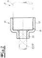
- Fig. 2
- einen Schnitt durch eine erfindungsgemäße Verschlusskappe.
- Fig. 1
- a view of an assembly according to the invention from a connector and a media line connected to it and
- Fig. 2
- a section through a closure cap according to the invention.
Der Verbinder 1 weist ein Innenteil 3 mit einem nicht näher dargestellten inneren Leitungskanal zur Durchleitung der wässrigen Harnstofflösung auf. Der Verbinder 1 bzw. der innere Leitungskanal des Verbinders 1 wird bevorzugt und im Ausführungsbeispiel mit Hilfe eines elektrisch betriebenen Heizdrahtes 4 beheizt.The connector 1 has an
Im Ausführungsbeispiel und nach bevorzugter Ausführungsform der Erfindung weist die Medienleitung 2 ein Innenrohr 5 zur Durchleitung der wässrigen Harnstofflösung auf sowie ein das Innenrohr 5 umgebendes Außenrohr 6. Vorzugsweise und im Ausführungsbeispiel umgibt ein Heizdraht 7 zur Beheizung der Medienleitung 2 das Innenrohr 5 wendelförmig. Zwischen Innenrohr 5 und Außenrohr 6 ist bevorzugt und im Ausführungsbeispiel fernerhin eine Zwischenschicht in Form eines wendelförmig um das Aggregat aus Innenrohr 5 und Heizdraht 7 gewickeltes Klebeband 8 vorgesehen. Mit Hilfe des Klebebandes 8 wird insbesondere der Heizdraht 7 an dem Innenrohr 5 fixiert.In the exemplary embodiment and according to a preferred embodiment of the invention, the
Der Verbinder 1 weist einen gegossenen und/oder gespitzten Außenmantel 9 aus thermoplastischem Kunststoff auf. Dieser Außenmantel 9 wird zweckmäßigerweise realisiert, indem schmelzflüssiger thermoplastischer Kunststoff um das Innenteil 3 des Verbinders 1 gegossen und/oder gespritzt wird. Erfindungsgemäß weist die Medienleitung 2 an einem dem Verbinder 1 zugewandten Ende eine Verschlusskappe 10 auf, die ein Eindringen von schmelzflüssigem Kunststoff in die Medienleitung 2 beim Gießen und/oder Spritzen des Außenmantels 9 verhindert. Die erfindungsgemäße Verschlusskappe 10 erfüllt also gleichsam eine Abdichtfunktion für die Medienleitung 2 gegenüber dem schmelzflüssigen Kunststoff.The connector 1 has a cast and / or tipped outer jacket 9 made of thermoplastic material. This outer jacket 9 is expediently realized by pouring and / or injecting molten thermoplastic material around the
Zweckmäßigerweise und im Ausführungsbeispiel übergreift die erfindungsgemäße Verschlusskappe 10 ein stirnseitiges Ende 11 des Außenrohres 6. Dazu weist die Verschlusskappe 10 einen ersten zylinderförmigen Abschnitt 12 in Form eines ringförmigen Flansches auf. In der in
Claims (11)
- An aggregate comprised of a connector (1)-in particular a quick connector-and a media line (2) hooked up to the connector (1), in particular a heatable media line (2), wherein the connector (1) has a cast and/or sprayed jacket, in particular an outer jacket (9) made out of plastic, and wherein an end of the media line (2) facing the connector (1) has a sealing cap (10), which prevents molten plastic from penetrating into the media line (2) while casting and/or spraying the jacket, wherein the sealing cap (10) has a first cylindrical section (12) and a second cylindrical section (13), wherein the first cylindrical section has a larger diameter than the second cylindrical section, wherein the first cylindrical section of the sealing cap (10) directly adjoins the second cylindrical section, wherein the first cylindrical section of the sealing cap (10) overlaps an outer pipe of the media line, and wherein the length of the sealing cap (10) is less than the length of the connector (1) in the longitudinal direction of the connector (1).
- The aggregate according to claim 1, wherein the aggregate is part of an SCR system for a vehicle, wherein a urea solution can be supplied to the SCR catalytic converter with the media line (2), and wherein the media line (2) can be heated with at least one heating element.
- The aggregate according to claim 2, wherein the connector (1) has an inner line channel for conducting the urea solution, and wherein the connector (1) or inner line channel can preferably be heated with at least one heating element.
- The aggregate according to one of claims 1 to 3, wherein the media line (2) has an inner pipe (5) and an outer pipe (6) that envelops the inner pipe (5), and wherein at least one heating element for heating the inner pipe (5) is arranged between the inner pipe (5) and outer pipe (6).
- The aggregate according to claim 4, wherein an intermediate layer is provided between the inner pipe (5) and outer pipe (6), and wherein the at least one heating element is arranged between the inner pipe (5) and intermediate layer.
- The aggregate according to one of claims 4 or 5, wherein the sealing cap (10) overlaps a front end (11) of the outer pipe (6).
- The aggregate according to one of claims 4 to 6, wherein the inner pipe (5) passes through the sealing cap (10).
- The aggregate according to one of claims 1 to 7, wherein the sealing cap (10) consists of a thermoplastic elastomer or essentially of a thermoplastic elastomer.
- The aggregate according to one of claims 1 to 8, wherein the sealing cap consists of EPDM or essentially of EPDM.
- The aggregate according to one of claims 1 to 9, wherein the connector (1) has an inner part (3), and wherein the outer jacket (9) is cast and/or sprayed around the inner part.
- The aggregate according to one of claims 1 to 10, wherein at least areas of the sealing cap (10) are covered by the outer jacket (9).
Applications Claiming Priority (1)
| Application Number | Priority Date | Filing Date | Title |
|---|---|---|---|
| DE202012101885U DE202012101885U1 (en) | 2012-05-23 | 2012-05-23 | Aggregate of a connector and a media line |
Publications (3)
| Publication Number | Publication Date |
|---|---|
| EP2667075A2 EP2667075A2 (en) | 2013-11-27 |
| EP2667075A3 EP2667075A3 (en) | 2016-07-06 |
| EP2667075B1 true EP2667075B1 (en) | 2020-02-19 |
Family
ID=46547421
Family Applications (1)
| Application Number | Title | Priority Date | Filing Date |
|---|---|---|---|
| EP13167477.2A Active EP2667075B1 (en) | 2012-05-23 | 2013-05-13 | Connection system consisting of a connector and a media line |
Country Status (2)
| Country | Link |
|---|---|
| EP (1) | EP2667075B1 (en) |
| DE (1) | DE202012101885U1 (en) |
Family Cites Families (3)
| Publication number | Priority date | Publication date | Assignee | Title |
|---|---|---|---|---|
| SE0401557D0 (en) * | 2004-06-15 | 2004-06-15 | Volvo Lastvagnar Ab | Electric heating coupler and enclosed liquid hose with electrically heated coupler |
| DE102006006211B3 (en) * | 2006-02-09 | 2007-09-20 | Rehau Ag + Co | Assembly for conducting and tempering a urea-water solution and method for the production thereof |
| DE102010026827A1 (en) * | 2010-07-12 | 2012-01-12 | Daimler Ag | Device for connecting a line element to a component |
-
2012
- 2012-05-23 DE DE202012101885U patent/DE202012101885U1/en not_active Expired - Lifetime
-
2013
- 2013-05-13 EP EP13167477.2A patent/EP2667075B1/en active Active
Non-Patent Citations (1)
| Title |
|---|
| None * |
Also Published As
| Publication number | Publication date |
|---|---|
| EP2667075A2 (en) | 2013-11-27 |
| EP2667075A3 (en) | 2016-07-06 |
| DE202012101885U1 (en) | 2012-06-15 |
Similar Documents
| Publication | Publication Date | Title |
|---|---|---|
| EP2910835B1 (en) | Heatable fluid line | |
| EP1818588B1 (en) | Hose arrangement and its production method | |
| EP3276243B1 (en) | Fluid line for motor vehicle | |
| EP2653770B1 (en) | Connector, in particular quick connector | |
| EP2527703B1 (en) | Fluid conduit | |
| WO2011032709A1 (en) | Heating arrangement | |
| DE202007010502U1 (en) | Ready-made media line | |
| EP2653765B1 (en) | Pipe for a fluid to be warmed up | |
| DE102008041723A1 (en) | Tank for storing a liquid agent | |
| WO2015185453A1 (en) | Heating module and tank system | |
| WO2009052849A1 (en) | Method for producing a system for guiding and controlling the temperature of a urea/water solution, and apparatus for carrying out the method | |
| EP3211190A1 (en) | Connector assembly with at least one connector and at least one fluid line | |
| WO2012143135A2 (en) | Media line | |
| WO2010046152A1 (en) | Dosing system for a liquid medium, particularly a urea-water solution | |
| EP2667075B1 (en) | Connection system consisting of a connector and a media line | |
| EP2420715A2 (en) | Insulation and/or protective covering for heatable connectors | |
| DE102009047334A1 (en) | Tank for storing urea water solution in exhaust gas post-treating system of internal-combustion engine, has two walls, where heating element is integrated into one of walls of tank, and tank is made of plastic | |
| EP2662606B1 (en) | Protective corrugated tubes for a pipe with a medium to be tempered, pipe module thereof | |
| DE102009040930B4 (en) | Heatable liquid container made of plastic material and process for its production | |
| DE202008007392U1 (en) | Fluid line and pipe connector for guiding and heating a medium | |
| WO2016142107A1 (en) | Container for a liquid working fluid of a motor vehicle and motor vehicle comprising such a container | |
| DE202014103393U1 (en) | Connector and connector assembly made of connector and piping | |
| EP2295888B1 (en) | Water heater | |
| DE102008042096A1 (en) | Extraction element for use as insert for inserting into container, has recess formed such that suction line is brought into ribs in two different angle positions relative to concave surface area | |
| DE20320585U1 (en) | A method for winding a heating wire over a fluid heating plastic tube has a first winding covered by an adhesive ribbon beneath a second winding |
Legal Events
| Date | Code | Title | Description |
|---|---|---|---|
| PUAI | Public reference made under article 153(3) epc to a published international application that has entered the european phase |
Free format text: ORIGINAL CODE: 0009012 |
|
| AK | Designated contracting states |
Kind code of ref document: A2 Designated state(s): AL AT BE BG CH CY CZ DE DK EE ES FI FR GB GR HR HU IE IS IT LI LT LU LV MC MK MT NL NO PL PT RO RS SE SI SK SM TR |
|
| AX | Request for extension of the european patent |
Extension state: BA ME |
|
| PUAL | Search report despatched |
Free format text: ORIGINAL CODE: 0009013 |
|
| AK | Designated contracting states |
Kind code of ref document: A3 Designated state(s): AL AT BE BG CH CY CZ DE DK EE ES FI FR GB GR HR HU IE IS IT LI LT LU LV MC MK MT NL NO PL PT RO RS SE SI SK SM TR |
|
| AX | Request for extension of the european patent |
Extension state: BA ME |
|
| RIC1 | Information provided on ipc code assigned before grant |
Ipc: F16L 33/34 20060101AFI20160527BHEP Ipc: F16L 53/00 20060101ALI20160527BHEP |
|
| 17P | Request for examination filed |
Effective date: 20160923 |
|
| RBV | Designated contracting states (corrected) |
Designated state(s): AL AT BE BG CH CY CZ DE DK EE ES FI FR GB GR HR HU IE IS IT LI LT LU LV MC MK MT NL NO PL PT RO RS SE SI SK SM TR |
|
| STAA | Information on the status of an ep patent application or granted ep patent |
Free format text: STATUS: EXAMINATION IS IN PROGRESS |
|
| 17Q | First examination report despatched |
Effective date: 20180426 |
|
| RIC1 | Information provided on ipc code assigned before grant |
Ipc: F16L 33/34 20060101AFI20190822BHEP Ipc: F16L 53/38 20180101ALI20190822BHEP Ipc: B29C 70/76 20060101ALI20190822BHEP |
|
| GRAP | Despatch of communication of intention to grant a patent |
Free format text: ORIGINAL CODE: EPIDOSNIGR1 |
|
| STAA | Information on the status of an ep patent application or granted ep patent |
Free format text: STATUS: GRANT OF PATENT IS INTENDED |
|
| INTG | Intention to grant announced |
Effective date: 20190927 |
|
| GRAS | Grant fee paid |
Free format text: ORIGINAL CODE: EPIDOSNIGR3 |
|
| GRAA | (expected) grant |
Free format text: ORIGINAL CODE: 0009210 |
|
| STAA | Information on the status of an ep patent application or granted ep patent |
Free format text: STATUS: THE PATENT HAS BEEN GRANTED |
|
| AK | Designated contracting states |
Kind code of ref document: B1 Designated state(s): AL AT BE BG CH CY CZ DE DK EE ES FI FR GB GR HR HU IE IS IT LI LT LU LV MC MK MT NL NO PL PT RO RS SE SI SK SM TR |
|
| REG | Reference to a national code |
Ref country code: GB Ref legal event code: FG4D Free format text: NOT ENGLISH |
|
| REG | Reference to a national code |
Ref country code: CH Ref legal event code: EP |
|
| REG | Reference to a national code |
Ref country code: DE Ref legal event code: R096 Ref document number: 502013014303 Country of ref document: DE |
|
| REG | Reference to a national code |
Ref country code: AT Ref legal event code: REF Ref document number: 1235365 Country of ref document: AT Kind code of ref document: T Effective date: 20200315 |
|
| REG | Reference to a national code |
Ref country code: IE Ref legal event code: FG4D Free format text: LANGUAGE OF EP DOCUMENT: GERMAN |
|
| REG | Reference to a national code |
Ref country code: NL Ref legal event code: MP Effective date: 20200219 |
|
| PG25 | Lapsed in a contracting state [announced via postgrant information from national office to epo] |
Ref country code: RS Free format text: LAPSE BECAUSE OF FAILURE TO SUBMIT A TRANSLATION OF THE DESCRIPTION OR TO PAY THE FEE WITHIN THE PRESCRIBED TIME-LIMIT Effective date: 20200219 Ref country code: FI Free format text: LAPSE BECAUSE OF FAILURE TO SUBMIT A TRANSLATION OF THE DESCRIPTION OR TO PAY THE FEE WITHIN THE PRESCRIBED TIME-LIMIT Effective date: 20200219 Ref country code: NO Free format text: LAPSE BECAUSE OF FAILURE TO SUBMIT A TRANSLATION OF THE DESCRIPTION OR TO PAY THE FEE WITHIN THE PRESCRIBED TIME-LIMIT Effective date: 20200519 |
|
| REG | Reference to a national code |
Ref country code: LT Ref legal event code: MG4D |
|
| PG25 | Lapsed in a contracting state [announced via postgrant information from national office to epo] |
Ref country code: SE Free format text: LAPSE BECAUSE OF FAILURE TO SUBMIT A TRANSLATION OF THE DESCRIPTION OR TO PAY THE FEE WITHIN THE PRESCRIBED TIME-LIMIT Effective date: 20200219 Ref country code: LV Free format text: LAPSE BECAUSE OF FAILURE TO SUBMIT A TRANSLATION OF THE DESCRIPTION OR TO PAY THE FEE WITHIN THE PRESCRIBED TIME-LIMIT Effective date: 20200219 Ref country code: HR Free format text: LAPSE BECAUSE OF FAILURE TO SUBMIT A TRANSLATION OF THE DESCRIPTION OR TO PAY THE FEE WITHIN THE PRESCRIBED TIME-LIMIT Effective date: 20200219 Ref country code: IS Free format text: LAPSE BECAUSE OF FAILURE TO SUBMIT A TRANSLATION OF THE DESCRIPTION OR TO PAY THE FEE WITHIN THE PRESCRIBED TIME-LIMIT Effective date: 20200619 Ref country code: GR Free format text: LAPSE BECAUSE OF FAILURE TO SUBMIT A TRANSLATION OF THE DESCRIPTION OR TO PAY THE FEE WITHIN THE PRESCRIBED TIME-LIMIT Effective date: 20200520 Ref country code: BG Free format text: LAPSE BECAUSE OF FAILURE TO SUBMIT A TRANSLATION OF THE DESCRIPTION OR TO PAY THE FEE WITHIN THE PRESCRIBED TIME-LIMIT Effective date: 20200519 |
|
| PG25 | Lapsed in a contracting state [announced via postgrant information from national office to epo] |
Ref country code: NL Free format text: LAPSE BECAUSE OF FAILURE TO SUBMIT A TRANSLATION OF THE DESCRIPTION OR TO PAY THE FEE WITHIN THE PRESCRIBED TIME-LIMIT Effective date: 20200219 |
|
| PG25 | Lapsed in a contracting state [announced via postgrant information from national office to epo] |
Ref country code: RO Free format text: LAPSE BECAUSE OF FAILURE TO SUBMIT A TRANSLATION OF THE DESCRIPTION OR TO PAY THE FEE WITHIN THE PRESCRIBED TIME-LIMIT Effective date: 20200219 Ref country code: CZ Free format text: LAPSE BECAUSE OF FAILURE TO SUBMIT A TRANSLATION OF THE DESCRIPTION OR TO PAY THE FEE WITHIN THE PRESCRIBED TIME-LIMIT Effective date: 20200219 Ref country code: PT Free format text: LAPSE BECAUSE OF FAILURE TO SUBMIT A TRANSLATION OF THE DESCRIPTION OR TO PAY THE FEE WITHIN THE PRESCRIBED TIME-LIMIT Effective date: 20200712 Ref country code: SM Free format text: LAPSE BECAUSE OF FAILURE TO SUBMIT A TRANSLATION OF THE DESCRIPTION OR TO PAY THE FEE WITHIN THE PRESCRIBED TIME-LIMIT Effective date: 20200219 Ref country code: EE Free format text: LAPSE BECAUSE OF FAILURE TO SUBMIT A TRANSLATION OF THE DESCRIPTION OR TO PAY THE FEE WITHIN THE PRESCRIBED TIME-LIMIT Effective date: 20200219 Ref country code: ES Free format text: LAPSE BECAUSE OF FAILURE TO SUBMIT A TRANSLATION OF THE DESCRIPTION OR TO PAY THE FEE WITHIN THE PRESCRIBED TIME-LIMIT Effective date: 20200219 Ref country code: LT Free format text: LAPSE BECAUSE OF FAILURE TO SUBMIT A TRANSLATION OF THE DESCRIPTION OR TO PAY THE FEE WITHIN THE PRESCRIBED TIME-LIMIT Effective date: 20200219 Ref country code: DK Free format text: LAPSE BECAUSE OF FAILURE TO SUBMIT A TRANSLATION OF THE DESCRIPTION OR TO PAY THE FEE WITHIN THE PRESCRIBED TIME-LIMIT Effective date: 20200219 Ref country code: SK Free format text: LAPSE BECAUSE OF FAILURE TO SUBMIT A TRANSLATION OF THE DESCRIPTION OR TO PAY THE FEE WITHIN THE PRESCRIBED TIME-LIMIT Effective date: 20200219 |
|
| REG | Reference to a national code |
Ref country code: DE Ref legal event code: R097 Ref document number: 502013014303 Country of ref document: DE |
|
| PLBE | No opposition filed within time limit |
Free format text: ORIGINAL CODE: 0009261 |
|
| STAA | Information on the status of an ep patent application or granted ep patent |
Free format text: STATUS: NO OPPOSITION FILED WITHIN TIME LIMIT |
|
| 26N | No opposition filed |
Effective date: 20201120 |
|
| PG25 | Lapsed in a contracting state [announced via postgrant information from national office to epo] |
Ref country code: LI Free format text: LAPSE BECAUSE OF NON-PAYMENT OF DUE FEES Effective date: 20200531 Ref country code: IT Free format text: LAPSE BECAUSE OF FAILURE TO SUBMIT A TRANSLATION OF THE DESCRIPTION OR TO PAY THE FEE WITHIN THE PRESCRIBED TIME-LIMIT Effective date: 20200219 Ref country code: CH Free format text: LAPSE BECAUSE OF NON-PAYMENT OF DUE FEES Effective date: 20200531 Ref country code: MC Free format text: LAPSE BECAUSE OF FAILURE TO SUBMIT A TRANSLATION OF THE DESCRIPTION OR TO PAY THE FEE WITHIN THE PRESCRIBED TIME-LIMIT Effective date: 20200219 |
|
| PG25 | Lapsed in a contracting state [announced via postgrant information from national office to epo] |
Ref country code: PL Free format text: LAPSE BECAUSE OF FAILURE TO SUBMIT A TRANSLATION OF THE DESCRIPTION OR TO PAY THE FEE WITHIN THE PRESCRIBED TIME-LIMIT Effective date: 20200219 Ref country code: SI Free format text: LAPSE BECAUSE OF FAILURE TO SUBMIT A TRANSLATION OF THE DESCRIPTION OR TO PAY THE FEE WITHIN THE PRESCRIBED TIME-LIMIT Effective date: 20200219 |
|
| REG | Reference to a national code |
Ref country code: BE Ref legal event code: MM Effective date: 20200531 |
|
| GBPC | Gb: european patent ceased through non-payment of renewal fee |
Effective date: 20200519 |
|
| PG25 | Lapsed in a contracting state [announced via postgrant information from national office to epo] |
Ref country code: LU Free format text: LAPSE BECAUSE OF NON-PAYMENT OF DUE FEES Effective date: 20200513 |
|
| PG25 | Lapsed in a contracting state [announced via postgrant information from national office to epo] |
Ref country code: GB Free format text: LAPSE BECAUSE OF NON-PAYMENT OF DUE FEES Effective date: 20200519 Ref country code: IE Free format text: LAPSE BECAUSE OF NON-PAYMENT OF DUE FEES Effective date: 20200513 |
|
| PG25 | Lapsed in a contracting state [announced via postgrant information from national office to epo] |
Ref country code: BE Free format text: LAPSE BECAUSE OF NON-PAYMENT OF DUE FEES Effective date: 20200531 |
|
| REG | Reference to a national code |
Ref country code: AT Ref legal event code: MM01 Ref document number: 1235365 Country of ref document: AT Kind code of ref document: T Effective date: 20200513 |
|
| PG25 | Lapsed in a contracting state [announced via postgrant information from national office to epo] |
Ref country code: AT Free format text: LAPSE BECAUSE OF NON-PAYMENT OF DUE FEES Effective date: 20200513 |
|
| PG25 | Lapsed in a contracting state [announced via postgrant information from national office to epo] |
Ref country code: TR Free format text: LAPSE BECAUSE OF FAILURE TO SUBMIT A TRANSLATION OF THE DESCRIPTION OR TO PAY THE FEE WITHIN THE PRESCRIBED TIME-LIMIT Effective date: 20200219 Ref country code: MT Free format text: LAPSE BECAUSE OF FAILURE TO SUBMIT A TRANSLATION OF THE DESCRIPTION OR TO PAY THE FEE WITHIN THE PRESCRIBED TIME-LIMIT Effective date: 20200219 Ref country code: CY Free format text: LAPSE BECAUSE OF FAILURE TO SUBMIT A TRANSLATION OF THE DESCRIPTION OR TO PAY THE FEE WITHIN THE PRESCRIBED TIME-LIMIT Effective date: 20200219 |
|
| PG25 | Lapsed in a contracting state [announced via postgrant information from national office to epo] |
Ref country code: MK Free format text: LAPSE BECAUSE OF FAILURE TO SUBMIT A TRANSLATION OF THE DESCRIPTION OR TO PAY THE FEE WITHIN THE PRESCRIBED TIME-LIMIT Effective date: 20200219 Ref country code: AL Free format text: LAPSE BECAUSE OF FAILURE TO SUBMIT A TRANSLATION OF THE DESCRIPTION OR TO PAY THE FEE WITHIN THE PRESCRIBED TIME-LIMIT Effective date: 20200219 |
|
| PGFP | Annual fee paid to national office [announced via postgrant information from national office to epo] |
Ref country code: FR Payment date: 20220524 Year of fee payment: 10 Ref country code: DE Payment date: 20220519 Year of fee payment: 10 |
|
| P01 | Opt-out of the competence of the unified patent court (upc) registered |
Effective date: 20230524 |
|
| REG | Reference to a national code |
Ref country code: DE Ref legal event code: R119 Ref document number: 502013014303 Country of ref document: DE |
|
| PG25 | Lapsed in a contracting state [announced via postgrant information from national office to epo] |
Ref country code: DE Free format text: LAPSE BECAUSE OF NON-PAYMENT OF DUE FEES Effective date: 20231201 |