EP2653770B1 - Connector, in particular quick connector - Google Patents
Connector, in particular quick connector Download PDFInfo
- Publication number
- EP2653770B1 EP2653770B1 EP12164969.3A EP12164969A EP2653770B1 EP 2653770 B1 EP2653770 B1 EP 2653770B1 EP 12164969 A EP12164969 A EP 12164969A EP 2653770 B1 EP2653770 B1 EP 2653770B1
- Authority
- EP
- European Patent Office
- Prior art keywords
- pipe
- connector
- webs
- outer tube
- connector according
- Prior art date
- Legal status (The legal status is an assumption and is not a legal conclusion. Google has not performed a legal analysis and makes no representation as to the accuracy of the status listed.)
- Not-in-force
Links
Images


Classifications
-
- F—MECHANICAL ENGINEERING; LIGHTING; HEATING; WEAPONS; BLASTING
- F16—ENGINEERING ELEMENTS AND UNITS; GENERAL MEASURES FOR PRODUCING AND MAINTAINING EFFECTIVE FUNCTIONING OF MACHINES OR INSTALLATIONS; THERMAL INSULATION IN GENERAL
- F16L—PIPES; JOINTS OR FITTINGS FOR PIPES; SUPPORTS FOR PIPES, CABLES OR PROTECTIVE TUBING; MEANS FOR THERMAL INSULATION IN GENERAL
- F16L53/00—Heating of pipes or pipe systems; Cooling of pipes or pipe systems
- F16L53/30—Heating of pipes or pipe systems
- F16L53/32—Heating of pipes or pipe systems using hot fluids
-
- F—MECHANICAL ENGINEERING; LIGHTING; HEATING; WEAPONS; BLASTING
- F01—MACHINES OR ENGINES IN GENERAL; ENGINE PLANTS IN GENERAL; STEAM ENGINES
- F01N—GAS-FLOW SILENCERS OR EXHAUST APPARATUS FOR MACHINES OR ENGINES IN GENERAL; GAS-FLOW SILENCERS OR EXHAUST APPARATUS FOR INTERNAL-COMBUSTION ENGINES
- F01N3/00—Exhaust or silencing apparatus having means for purifying, rendering innocuous, or otherwise treating exhaust
- F01N3/08—Exhaust or silencing apparatus having means for purifying, rendering innocuous, or otherwise treating exhaust for rendering innocuous
- F01N3/10—Exhaust or silencing apparatus having means for purifying, rendering innocuous, or otherwise treating exhaust for rendering innocuous by thermal or catalytic conversion of noxious components of exhaust
-
- F—MECHANICAL ENGINEERING; LIGHTING; HEATING; WEAPONS; BLASTING
- F16—ENGINEERING ELEMENTS AND UNITS; GENERAL MEASURES FOR PRODUCING AND MAINTAINING EFFECTIVE FUNCTIONING OF MACHINES OR INSTALLATIONS; THERMAL INSULATION IN GENERAL
- F16L—PIPES; JOINTS OR FITTINGS FOR PIPES; SUPPORTS FOR PIPES, CABLES OR PROTECTIVE TUBING; MEANS FOR THERMAL INSULATION IN GENERAL
- F16L11/00—Hoses, i.e. flexible pipes
- F16L11/04—Hoses, i.e. flexible pipes made of rubber or flexible plastics
- F16L11/12—Hoses, i.e. flexible pipes made of rubber or flexible plastics with arrangements for particular purposes, e.g. specially profiled, with protecting layer, heated, electrically conducting
-
- F—MECHANICAL ENGINEERING; LIGHTING; HEATING; WEAPONS; BLASTING
- F16—ENGINEERING ELEMENTS AND UNITS; GENERAL MEASURES FOR PRODUCING AND MAINTAINING EFFECTIVE FUNCTIONING OF MACHINES OR INSTALLATIONS; THERMAL INSULATION IN GENERAL
- F16L—PIPES; JOINTS OR FITTINGS FOR PIPES; SUPPORTS FOR PIPES, CABLES OR PROTECTIVE TUBING; MEANS FOR THERMAL INSULATION IN GENERAL
- F16L37/00—Couplings of the quick-acting type
- F16L37/56—Couplings of the quick-acting type for double-walled or multi-channel pipes or pipe assemblies
- F16L37/565—Concentric pipes
-
- F—MECHANICAL ENGINEERING; LIGHTING; HEATING; WEAPONS; BLASTING
- F16—ENGINEERING ELEMENTS AND UNITS; GENERAL MEASURES FOR PRODUCING AND MAINTAINING EFFECTIVE FUNCTIONING OF MACHINES OR INSTALLATIONS; THERMAL INSULATION IN GENERAL
- F16L—PIPES; JOINTS OR FITTINGS FOR PIPES; SUPPORTS FOR PIPES, CABLES OR PROTECTIVE TUBING; MEANS FOR THERMAL INSULATION IN GENERAL
- F16L9/00—Rigid pipes
- F16L9/18—Double-walled pipes; Multi-channel pipes or pipe assemblies
-
- F—MECHANICAL ENGINEERING; LIGHTING; HEATING; WEAPONS; BLASTING
- F28—HEAT EXCHANGE IN GENERAL
- F28D—HEAT-EXCHANGE APPARATUS, NOT PROVIDED FOR IN ANOTHER SUBCLASS, IN WHICH THE HEAT-EXCHANGE MEDIA DO NOT COME INTO DIRECT CONTACT
- F28D7/00—Heat-exchange apparatus having stationary tubular conduit assemblies for both heat-exchange media, the media being in contact with different sides of a conduit wall
- F28D7/10—Heat-exchange apparatus having stationary tubular conduit assemblies for both heat-exchange media, the media being in contact with different sides of a conduit wall the conduits being arranged one within the other, e.g. concentrically
- F28D7/103—Heat-exchange apparatus having stationary tubular conduit assemblies for both heat-exchange media, the media being in contact with different sides of a conduit wall the conduits being arranged one within the other, e.g. concentrically consisting of more than two coaxial conduits or modules of more than two coaxial conduits
Definitions
- the invention relates to a connector, in particular a quick connector for the connection of at least one, a fluid medium to be tempered, in particular leading to tempering urea solution pipeline.
- the pipeline can be connected to another pipeline or to another component, for example to a tank for a fluid medium or the like.
- the connector or quick connector according to the invention is designed according to a particularly preferred embodiment for a detachable connection with another component or pipe.
- to be tempered fluid medium is meant in particular a liquid medium to be tempered.
- GB 2 290 848 A discloses a multi-duct piping for transporting fluid media which may be considered as a connector. It is also already known to guide a urea solution to be tempered in the context of an SCR system through such a connector or quick connector.
- SCR Selective Catalytic Reduction
- a urea solution is metered into the exhaust gas upstream of an SCR catalytic converter.
- Such a urea solution or aqueous urea solution has the disadvantage that urea freezes at temperatures below -11 ° C and partially crystallized. As a result, a further functionally reliable supply of urea solution is hindered or completely blocked and impairs or prevents effective reduction of the nitrogen oxides in the exhaust gas.
- the supply lines or pipes for the urea solution are heated. It is already known, one to such To heat pipe connected connector or quick connector. The heating is performed as an electrical heating and for this purpose one or more heating wires are arranged on the connector or quick connector. In principle, it is already known to carry out heating of fluid-carrying systems with the aid of heated liquid media. The most known measures have the disadvantage that they are expensive or expensive to implement and / or sufficiently effective temperature control or heating of the fluid medium to be tempered or the urea solution to be tempered is not guaranteed.
- the invention is the technical problem of specifying a connector and in particular a quick connector of the type mentioned, which can be produced in a simple and inexpensive manner and with the same time a very effective temperature control of a fluid medium or a urea solution is possible.
- the invention teaches a connector, in particular a quick connector for the connection of at least one, a fluid medium to be tempered, in particular leading to tempering urea solution pipeline, according to claim 1.
- the connector or quick connector according to the invention is connected to a pipe or to another pipeline and then expediently serves to connect two pipes or at least two pipes. It is within the scope of the invention that the connector or quick connector according to the invention is connected to a further connector. A plug element of a connector according to the invention can then be plugged into a socket element of the further connector or vice versa.
- the connector according to the invention can also be used for connecting a pipeline to another component, for example to a tank or to an injection nozzle or the like.
- a quick connector is meant, which can be used in particular for a releasable connection with another component.
- the fluid medium to be tempered is preferably a liquid medium to be tempered, in particular a liquid medium to be heated. It is within the scope of the invention that the fluid medium to be tempered is a urea solution or an aqueous urea solution.
- a connector according to the invention for the passage of the urea solution to be tempered or heated is part of an SCR system in a motor vehicle.
- the fluid temperature control medium serves for tempering or for heating the fluid medium to be tempered. It is within the scope of the invention that the fluid temperature control medium is a heated liquid temperature control medium.
- a recommended embodiment of the invention is characterized in that in the inner tube to be tempered fluid medium is received or flows and that in the at least one duct between the inner tube and outer tube, the fluid temperature control medium is received or flows.
- the inner wall of the outer tube is connected via a plurality of webs with the outer wall of the inner tube.
- the webs extend parallel to the longitudinal center axis M of the inner tube.
- the webs are integrally formed on the inner wall of the outer tube and on the outer wall of the inner tube. The webs run over the length of the aggregate of inner tube and outer tube.
- the space between the inner tube and outer tube is divided into a plurality of ducts.
- the webs are arranged distributed uniformly over the circumference of the inner tube or over the circumference of the outer tube. It is within the scope of the invention that the webs run parallel to each other along the pipe.
- the cross section of the inner tube, the outer tube and the webs limited conduit is the same size or substantially the same size. It is recommended that all ducts have the same cross-sectional shape or substantially the same cross-sectional shape.
- the inner wall of the outer tube is connected to the outer wall of the inner tube via at least two webs and preferably via at least three webs.
- the webs made of thermoplastic material or substantially of thermoplastic material.
- the assembly of inner tube, outer tube and webs is produced by injection molding or is produced as an injection molded part.
- An outer tube is provided.
- a preferred embodiment of the connector is characterized in that the assembly of inner tube and outer tube is disposed in the outer tube and is surrounded by the outer tube, in particular over the entire circumference of the unit is surrounded and that the outer tube parallel or in the Substantially extends parallel to the longitudinal center axis M of the inner tube. It is within the scope of the invention that between the outer tube and the outer tube at least one outer conduit is arranged, which is preferably flowed through by the fluid temperature control medium.
- outer tube, outer tube and inner tube and possibly with the webs is produced by injection molding or is produced as an injection molded part. It is also within the scope of the invention that this entire unit consists of a thermoplastic material or substantially of a thermoplastic material.
- a preferred embodiment of the invention is characterized in that in the inner tube, the fluid medium to be tempered is received or flows, that in the at least one duct between inner tube and outer tube, the fluid temperature control medium is received or flows and that in the at least one outer conduit between the outer tube and outer tube also the fluid temperature control medium is received or flows.
- Another embodiment of the invention is characterized in that in the inner tube, the fluid temperature control is received or flows, that in the at least one conduit between the inner tube and outer tube, the fluid to be tempered fluid is received or flows and that in the at least one outer conduit between the outer tube and outer tube, the fluid temperature control medium is received or flows.
- the inner wall of the outer tube is connected via a plurality of outer webs with the outer wall of the outer tube.
- the outer webs preferably extend parallel to the longitudinal center axis M of the inner tube. It is within the scope of the invention that the outer webs extend in the longitudinal direction of the connector. It is also within the scope of the invention that the outer webs are integrally formed on the inner wall of the outer tube and on the outer wall of the outer tube. Conveniently, the outer webs extend over the length of the outer tube or over the length of the outer tube without interruption or without gaps. It is within the scope of the invention that the outer webs subdivide the space between the outer tube and the outer tube into a plurality of outer conduit channels, wherein the outer conduit channels are preferably flowed through by the fluid temperature control medium.
- the outer webs are distributed uniformly over the circumference of the outer tube or over the circumference of the outer tube.
- the outer ducts separated by the outer webs have an equal cross section or a substantially equal cross section and preferably the same cross sectional shape.
- the inner wall of the outer tube via at least two outer webs, preferably at least three outer webs and preferably at least four outer webs connected to the outer wall of the outer tube.
- the outer webs consist of thermoplastic material or consist essentially of thermoplastic material.
- the entire assembly of outer tube, outer tube, inner tube and outer webs as well as possibly webs is produced by injection molding or produced as an injection molded part.
- the webs and / or the outer webs have a trapezoidal cross-section.
- the trapezoids are recommended to taper towards the middle of the connector.
- Center of the connector means here in particular the longitudinal center axis M of the inner tube.
- the webs are arranged offset relative to the outer webs with respect to the circumference of the outer tube.
- a web is arranged in relation to the circumference of the outer tube in the middle or approximately in the middle between two outer webs.
- the wall thickness of the inner tube and / or the wall thickness of the outer tube and / or the wall thickness of the outer tube is 0.6 to 3 mm, preferably 0.8 to 2.5 mm, preferably 0.9 to 2, 2 mm and more preferably 1 to 2 mm.
- the inner tube and / or the outer tube and / or the outer tube is cylindrical or substantially cylindrical in shape / are. It is also within the scope of the invention that the inner tube is arranged concentrically within the outer tube and / or that the outer tube or the assembly of inner tube and outer tube is arranged concentrically within the outer tube.
- a coaxial arrangement of inner tube and outer tube and / or outer tube and outer tube has proven itself within the scope of the invention.
- the radial width r i of a duct and / or the radial width r a of an outer duct is 0.5 to 3.0 mm, preferably 0.6 to 2.0 mm, preferably 0.8 to 1.5 mm and more preferably 0.8 to 1.2 mm.
- the connector according to the invention is part of a motor vehicle and that the temperature control medium is preferably heated coolant or heated cooling water and / or fuel or recirculated fuel.
- heated cooling water diverted from the cooling water circuit of the motor vehicle is used as the temperature control medium.
- fuel returned from the engine of the motor vehicle to the fuel tank is used as the temperature control medium.
- a preferred embodiment of the invention is characterized in that the tempering medium initially flows through the at least one duct between inner tube and outer tube in a first direction along the connector, that a deflection is provided for deflecting the temperature control in the at least one outer conduit between outer tube and outer tube and that the tempering medium flows through the at least one outer duct in a direction opposite to the first direction of the second direction along the connector.
- the temperature control medium is thus between the inner tube and outer tube on the one hand and between outer tube and outer tube on the other hand, as it were, conducted in countercurrent.
- the temperature control medium preferably flows through a plurality of ducts separated by the webs and through a plurality of outer ducts separated by the outer webs.
- the connector according to the invention has at least one connection piece for the supply of the fluid temperature control medium and / or at least one connection piece for the discharge of the fluid temperature control medium.
- the connector is equipped both with a connection piece for supplying the fluid temperature control medium and with a connecting piece for discharging the fluid temperature control medium.
- a connecting piece is designed as a plug element or sleeve element for the connection of a matching sleeve element or plug element. It is recommended that the connecting piece or the connecting piece are arranged perpendicular or substantially perpendicular to the longitudinal axis of the connector.
- the term longitudinal axis of the connector refers to the connector portion to which the connection piece or to which the connection piece is / are /. It is within the scope of the invention that the at least one connecting piece for supplying the fluid tempering medium to the ducts between the inner tube and outer tube is connected and / or that the at least one connecting piece for discharging the fluid temperature control medium is connected to the outer conduit between outer tube and outer tube.
- the connector according to the invention and in particular the aggregate of outer tube, outer tube, inner tube, webs and outer webs of thermoplastic material or substantially of thermoplastic material.
- the connector or the aforementioned aggregate consists of a polyamide or substantially of a polyamide.
- the polyamide may in particular be polyamide 12.
- the invention uses high-temperature-resistant plastics for the connector according to the invention. - It is within the scope of the invention that the connector according to the invention or in particular the aggregate of outer tube, outer tube, inner tube, webs and outer webs is produced by injection molding.
- the unit of inner tube, outer tube and outer tube is surrounded by at least one other outer tube and that inner tube, outer tube, outer tube and the at least one further outer tube are arranged concentrically to each other or coaxially.
- the other outer tube is connected via further outer webs with the outer tube. It is recommended that also flows through the gap or through the channels between the outer tube and further outer tube, the fluid temperature control medium, preferably in a direction opposite to the flow direction, with the tempering through the outer ducts between the outer tube and outer tube flows.
- the invention is based on the finding that a surprisingly effective temperature control of a fluid medium, in particular a urea solution, is possible with the connector according to the invention.
- a urea solution passed through the connector of the present invention can be effectively protected from freezing or crystallization in a simple and trouble-free manner.
- the connector according to the invention can be produced with relatively simple and inexpensive means. In a complex electrical heating with heating wires or the like can be dispensed with in an advantageous manner. It is possible to make use of the energy resources already present or already present in the motor vehicle without requiring an additional energy supply.
- One inventive connector can be realized or produced relatively inexpensively.
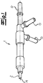
- the figures show a designed as a quick connector according to the invention connector 1 for the connection of a pipe to be tempered urea solution leading pipe 2 with another component, not shown, for example, with another connector or with another pipe.
- the pipe 2 is connected to the left end side of the connector 1.
- the connector 1 At the other front end or at the in the Fig. 1 and 2 right front end, the connector 1, a male member 4 for connection to a sleeve member, not shown, of a further component.
- the connector 1 in the embodiment of the Fig. 1 and 2 equipped with a connection piece 5 for the supply of a fluid temperature control medium and with a connection piece 6 for the discharge of the fluid temperature control medium.
- the Connecting pieces 5, 6 are formed as plug elements analogous to the plug element 4 at the one end face of the connector 1.
- the connector 1 has an inner tube 3 for the passage of the aqueous urea solution. This urea solution is fed to a SCR catalytic converter, not shown, of a motor vehicle.
- the inner tube 3 is surrounded by an outer tube 7, so that inner tube 3 and outer tube 7 are arranged concentrically or coaxially to each other (see in particular Fig. 3 ).
- the outer tube 7 or the aggregate of inner tube 3 and outer tube 7 is surrounded by an outer tube 8, so that the inner tube 3, the outer tube 7 and the outer tube 8 are arranged concentrically or coaxially to each other.
- Fig. 2 is very schematically the flow or the flow direction of the urea solution on the one hand and the fluid temperature control for the heating of the urea solution on the other hand indicated by arrows.
- the connector 1 shown in the figures is preferred and in the embodiment part of a motor vehicle and the fluid temperature control is in one embodiment to the cooling water circuit of the motor vehicle branched heated cooling water.
- the urea solution flows from the right to the left through the inner tube 3.
- the supplied via the connecting piece 5 fluid temperature control medium flows in the same direction as the urea solution through the space between the inner tube 3 and outer tube 7 and up to a deflection 9.
- the temperature control is in the deflection region 9 in the space between the outer tube 7 and the outer tube. 8 deflected and flows in the exemplary embodiment Fig. 2 in the opposite direction from left to right. Due to this configuration, a very effective temperature control of the urea solution in the inner tube 3 is achieved.
- the tempering then flows in the space between the outer tube 7 and outer tube 8 to the connecting piece 6 and is discharged there again.
- the connecting piece 6 is arranged at right angles to the connecting piece 5. Therefore, the connecting piece 6 in Fig. 2 obscured by the connector 1 and thus is not visible.
- the Fig. 3 shows a section through the connector 1 according to Fig. 2 , It can be seen that the inner wall of the outer tube 7 is connected in the embodiment via four webs 10 with the outer wall of the inner tube 3.
- the webs 10 preferably extend without interruption in the longitudinal direction of the aggregate of inner tube 3 and outer tube 7 or parallel to the longitudinal center axis M of the connector 1. In this way, the space between the inner tube 3 and the outer tube 7 in the embodiment in four ducts 11 for the divided by the fluid temperature control medium.
- the inner wall of the outer tube 8 is connected in the embodiment via four outer webs 12 with the outer wall of the outer tube 7.
- the outer webs 12 extend without interruption over the length of the aggregate of outer tube 7 and outer tube 8 in the longitudinal direction of the connector 1 and parallel to the longitudinal center axis M of the connector 1.
- the webs 10 and the outer webs 12 are arranged parallel to each other.
- the webs 10 and the outer webs 12 have a trapezoidal cross-section.
- the trapezoids preferably taper towards the center of the connector 1 or to the longitudinal central axis M down.
- the webs 10 are arranged offset with respect to the circumference of the outer tube 7 to the outer webs 12.
- a web 10 is arranged in the central region of the adjacent outer duct 13 and an outer web 12 is arranged in the central region of the adjacent duct 11.
- a comparative analysis of Fig. 2 and 3 takes it that, according to a preferred embodiment and in the embodiment, both the inner tube 3 and the outer tube 7 and also the outer tube 8 are formed cylindrical with a circular cross-section.
- the inner tube 3 is arranged concentrically within the outer tube 7 in the embodiment and the aggregate of inner tube 3 and outer tube 7 is arranged concentrically within the outer tube 8 in the embodiment.
- the inner diameter d of the inner tube 3 is preferably 2 to 6 mm.
- the radial width r i of a duct 11 is expediently 0.8 to 1.5 mm.
- the radial width r a of an outer conduit 13 is 0.8 to 1.5 mm.
- Empfohlene the wall thickness of the inner tube 3 and the wall thickness of the outer tube 7 and the wall thickness of the outer tube 8 is 0.9 to 2.2 mm.
- the fluid medium to be tempered or the urea solution can also flow through the conduit channels 11 between the inner tube 3 and the outer tube 7.
- the fluid temperature-control medium expediently flows through the inner tube 3 on the one hand and through the outer-passage channels 13 between the outer tube 7 and the outer tube 8 on the other hand.
Landscapes
- Engineering & Computer Science (AREA)
- General Engineering & Computer Science (AREA)
- Mechanical Engineering (AREA)
- Physics & Mathematics (AREA)
- Thermal Sciences (AREA)
- Chemical & Material Sciences (AREA)
- Toxicology (AREA)
- Chemical Kinetics & Catalysis (AREA)
- Health & Medical Sciences (AREA)
- Combustion & Propulsion (AREA)
- Exhaust Gas After Treatment (AREA)
- Rigid Pipes And Flexible Pipes (AREA)
- Joints With Sleeves (AREA)
- Pipe Accessories (AREA)
- Quick-Acting Or Multi-Walled Pipe Joints (AREA)
- Exhaust Gas Treatment By Means Of Catalyst (AREA)
Description
Die Erfindung betrifft einen Verbinder, insbesondere einen Schnellverbinder für die Verbindung zumindest einer, ein zu temperierendes fluides Medium, insbesondere eine zu temperierende Harnstofflösung führenden Rohrleitung. Mit dem Verbinder kann die Rohrleitung an eine weitere Rohrleitung angeschlossen werden oder an eine andere Komponente, beispielsweise an einen Tank für ein fluides Medium oder dergleichen. Der erfindungsgemäße Verbinder bzw. Schnellverbinder ist nach besonders bevorzugter Ausführungsform für eine lösbare Verbindung mit einer weiteren Komponente bzw. Rohrleitung ausgelegt. - Mit dem Begriff zu temperierendes fluides Medium ist insbesondere ein zu temperierendes flüssiges Medium gemeint.The invention relates to a connector, in particular a quick connector for the connection of at least one, a fluid medium to be tempered, in particular leading to tempering urea solution pipeline. With the connector, the pipeline can be connected to another pipeline or to another component, for example to a tank for a fluid medium or the like. The connector or quick connector according to the invention is designed according to a particularly preferred embodiment for a detachable connection with another component or pipe. - By the term to be tempered fluid medium is meant in particular a liquid medium to be tempered.
Verbinder bzw. Schnellverbinder der eingangs genannten Art sind aus der Praxis in verschiedenen Ausführungsformen bekannt.
Demgegenüber liegt der Erfindung das technische Problem zugrunde, einen Verbinder und insbesondere einen Schnellverbinder der eingangs genannten Art anzugeben, der auf einfache und wenig aufwendige Weise herstellbar ist und mit dem zugleich eine sehr effektive Temperierung eines fluiden Mediums bzw. einer Harnstofflösung möglich ist.In contrast, the invention is the technical problem of specifying a connector and in particular a quick connector of the type mentioned, which can be produced in a simple and inexpensive manner and with the same time a very effective temperature control of a fluid medium or a urea solution is possible.
Zur Lösung dieses technischen Problems lehrt die Erfindung einen Verbinder, insbesondere einen Schnellverbinder für die Verbindung zumindest einer, ein zu temperierendes fluides Medium, insbesondere eine zu temperierende Harnstofflösung führenden Rohrleitung, nach dem Anspruch 1. Nach einer Ausführungsform der Erfindung wird der erfindungsgemäße Verbinder bzw. Schnellverbinder mit einer Rohrleitung bzw. mit einer weiteren Rohrleitung verbunden und dient dann zweckmäßigerweise zur Verbindung von zwei Rohrleitungen oder von zumindest zwei Rohrleitungen. Es liegt im Rahmen der Erfindung, dass der erfindungsgemäße Verbinder bzw. Schnellverbinder mit einem weiteren Verbinder verbunden wird. Ein Steckerelement eines erfindungsgemäßen Verbinders kann dann in ein Muffenelement des weiteren Verbinders eingesteckt werden oder umgekehrt. Der erfindungsgemäße Verbinder kann auch zum Anschluss einer Rohrleitung an eine andere Komponente, beispielsweise an einen Tank oder an eine Einspritzdüse oder dergleichen eingesetzt werden. Soweit hier und nachfolgend von Verbinder die Rede ist, ist vorzugsweise ein Schnellverbinder gemeint, der insbesondere für eine lösbare Verbindung mit einer weiteren Komponente eingesetzt werden kann.To solve this technical problem, the invention teaches a connector, in particular a quick connector for the connection of at least one, a fluid medium to be tempered, in particular leading to tempering urea solution pipeline, according to
Bei dem zu temperierenden fluiden Medium handelt es sich bevorzugt um ein zu temperierendes flüssiges Medium und zwar insbesondere um ein zu erwärmendes flüssiges Medium. Es liegt im Rahmen der Erfindung, dass es sich bei dem zu temperierenden fluiden Medium um eine Harnstofflösung bzw. um eine wässrige Harnstofflösung handelt. Zweckmäßigerweise ist ein erfindungsgemäßer Verbinder für die Durchleitung der zu temperierenden bzw. zu erwärmenden Harnstofflösung Bestandteil eines SCR-Systems in einem Kraftfahrzeug.The fluid medium to be tempered is preferably a liquid medium to be tempered, in particular a liquid medium to be heated. It is within the scope of the invention that the fluid medium to be tempered is a urea solution or an aqueous urea solution. Appropriately, a connector according to the invention for the passage of the urea solution to be tempered or heated is part of an SCR system in a motor vehicle.
Das fluide Temperiermedium dient zur Temperierung bzw. zur Erwärmung des zu temperierenden fluiden Mediums. Es liegt im Rahmen der Erfindung, dass es sich bei dem fluiden Temperiermedium um ein erwärmtes flüssiges Temperiermedium handelt. - Eine empfohlene Ausführungsform der Erfindung zeichnet sich dadurch aus, dass in dem Innenrohr das zu temperierende fluide Medium aufgenommen ist bzw. strömt und dass in dem zumindest einen Leitungskanal zwischen Innenrohr und Außenrohr das fluide Temperiermedium aufgenommen ist bzw. strömt. Die Innenwand des Außenrohres ist über eine Mehrzahl von Stegen mit der Außenwand des Innenrohres verbunden. Bevorzugt erstrecken sich die Stege parallel zur Längsmittelachse M des Innenrohres. Die Stege sind an die Innenwand des Außenrohres und an die Außenwand des Innenrohres einstückig angeformt. Die Stege verlaufen über die Länge des Aggregates aus Innenrohr und Außenrohr. Durch die Stege wird der Raum zwischen Innenrohr und Außenrohr in eine Mehrzahl von Leitungskanälen unterteilt. Zweckmäßigerweise sind die Stege gleichmäßig über den Umfang des Innenrohres bzw. über den Umfang des Außenrohres verteilt angeordnet. Es liegt im Rahmen der Erfindung, dass die Stege parallel zueinander entlang der Rohrleitung verlaufen. Vorzugsweise ist der Querschnitt der vom Innenrohr, vom Außenrohr und den Stegen begrenzten Leitungskanäle gleich groß bzw. im Wesentlichen gleich groß. Es empfiehlt sich, dass alle Leitungskanäle die gleiche Querschnittsform bzw. im Wesentlichen die gleiche Querschnittsform aufweisen. Zweckmäßigerweise ist die Innenwand des Außenrohres mit der Außenwand des Innenrohres über zumindest zwei Stege und bevorzugt über zumindest drei Stege verbunden. - Vorzugsweise bestehen die Stege aus thermoplastischem Kunststoff bzw. im Wesentlichen aus thermoplastischem Kunststoff. Es liegt im Rahmen der Erfindung, dass das Aggregat aus Innenrohr, Außenrohr und Stegen durch Spritzgießen hergestellt wird bzw. als Spritzgussteil hergestellt wird. Ein äußeres Rohr ist vorgesehen. Eine bevorzugte Ausführungsform des Verbinders ist dadurch gekennzeichnet, dass das Aggregat aus Innenrohr und Außenrohr in dem äußeren Rohr angeordnet ist bzw. von dem äußeren Rohr umgeben wird, insbesondere über den gesamten Umfang des Aggregates umgeben wird und dass sich das äußere Rohr parallel bzw. im Wesentlichen parallel zur Längsmittelachse M des Innenrohres erstreckt. Es liegt im Rahmen der Erfindung, dass zwischen dem Außenrohr und dem äußeren Rohr zumindest ein Außenleitungskanal angeordnet ist, der bevorzugt von dem fluiden Temperiermedium durchströmt wird. - Es empfiehlt sich, dass das gesamte Aggregat aus äußerem Rohr, Außenrohr und Innenrohr sowie gegebenenfalls mit den Stegen durch Spritzgießen hergestellt wird bzw. als Spritzgussteil hergestellt wird. Es liegt fernerhin im Rahmen der Erfindung, dass dieses gesamte Aggregat aus einem thermoplastischen Kunststoff bzw. im Wesentlichen aus einem thermoplastischen Kunststoff besteht.The fluid temperature control medium serves for tempering or for heating the fluid medium to be tempered. It is within the scope of the invention that the fluid temperature control medium is a heated liquid temperature control medium. A recommended embodiment of the invention is characterized in that in the inner tube to be tempered fluid medium is received or flows and that in the at least one duct between the inner tube and outer tube, the fluid temperature control medium is received or flows. The inner wall of the outer tube is connected via a plurality of webs with the outer wall of the inner tube. Preferably, the webs extend parallel to the longitudinal center axis M of the inner tube. The webs are integrally formed on the inner wall of the outer tube and on the outer wall of the inner tube. The webs run over the length of the aggregate of inner tube and outer tube. By the webs, the space between the inner tube and outer tube is divided into a plurality of ducts. Conveniently, the webs are arranged distributed uniformly over the circumference of the inner tube or over the circumference of the outer tube. It is within the scope of the invention that the webs run parallel to each other along the pipe. Preferably, the cross section of the inner tube, the outer tube and the webs limited conduit is the same size or substantially the same size. It is recommended that all ducts have the same cross-sectional shape or substantially the same cross-sectional shape. Conveniently, the inner wall of the outer tube is connected to the outer wall of the inner tube via at least two webs and preferably via at least three webs. - Preferably, the webs made of thermoplastic material or substantially of thermoplastic material. It is within the scope of the invention that the assembly of inner tube, outer tube and webs is produced by injection molding or is produced as an injection molded part. An outer tube is provided. A preferred embodiment of the connector is characterized in that the assembly of inner tube and outer tube is disposed in the outer tube and is surrounded by the outer tube, in particular over the entire circumference of the unit is surrounded and that the outer tube parallel or in the Substantially extends parallel to the longitudinal center axis M of the inner tube. It is within the scope of the invention that between the outer tube and the outer tube at least one outer conduit is arranged, which is preferably flowed through by the fluid temperature control medium. - It is recommended that the entire assembly of outer tube, outer tube and inner tube and possibly with the webs is produced by injection molding or is produced as an injection molded part. It is also within the scope of the invention that this entire unit consists of a thermoplastic material or substantially of a thermoplastic material.
Eine bevorzugte Ausführungsform der Erfindung zeichnet sich dadurch aus, dass in dem Innenrohr das zu temperierende fluide Medium aufgenommen ist bzw. strömt, dass in dem zumindest einen Leitungskanal zwischen Innenrohr und Außenrohr das fluide Temperiermedium aufgenommen ist bzw. strömt und dass in dem zumindest einen Außenleitungskanal zwischen Außenrohr und äußerem Rohr ebenfalls das fluide Temperiermedium aufgenommen ist bzw. strömt. - Eine andere Ausführungsform der Erfindung ist dadurch gekennzeichnet, dass in dem Innenrohr das fluide Temperiermedium aufgenommen ist bzw. strömt, dass in dem zumindest einem Leitungskanal zwischen Innenrohr und Außenrohr das zu temperierende fluide Medium aufgenommen ist bzw. strömt und dass in dem zumindest einen Außenleitungskanal zwischen Außenrohr und äußerem Rohr das fluide Temperiermedium aufgenommen ist bzw. strömt. Die Innenwand des äußeren Rohres ist über eine Mehrzahl von Außenstegen mit der Außenwand des Außenrohres verbunden. Die Außenstege erstrecken sich bevorzugt parallel zur Längsmittelachse M des Innenrohres. Es liegt im Rahmen der Erfindung, dass sich die Außenstege in Längsrichtung des Verbinders erstrecken. Es liegt fernerhin im Rahmen der Erfindung, dass die Außenstege an die Innenwand des äußeren Rohres und an die Außenwand des Außenrohres einstückig angeformt sind. Zweckmäßigerweise verlaufen die Außenstege über die Länge des äußeren Rohres bzw. über die Länge des Außenrohres ohne Unterbrechung bzw. ohne Lücken. Es liegt im Rahmen der Erfindung, dass die Außenstege den Raum zwischen dem Außenrohr und dem äußeren Rohr in eine Mehrzahl von Außenleitungskanälen unterteilen, wobei die Außenleitungskanäle vorzugsweise von dem fluiden Temperiermedium durchströmt werden. Es empfiehlt sich, dass die Außenstege gleichmäßig über den Umfang des äußeren Rohres bzw. über den Umfang des Außenrohres verteilt angeordnet sind. Vorteilhafterweise haben die durch die Außenstege getrennten Außenleitungskanäle einen gleichgroßen Querschnitt bzw. einen im Wesentlichen gleich großen Querschnitt und bevorzugt die gleiche Querschnittsform. Zweckmäßigerweise ist die Innenwand des äußeren Rohres über zumindest zwei Außenstege, vorzugsweise zumindest drei Außenstege und bevorzugt zumindest vier Außenstege mit der Außenwand des Außenrohres verbunden. - Es liegt im Rahmen der Erfindung, dass die Außenstege aus thermoplastischem Kunststoff bestehen bzw. im Wesentlichen aus thermoplastischem Kunststoff bestehen. Vorzugsweise wird das gesamte Aggregat aus äußerem Rohr, Außenrohr, Innenrohr und Außenstegen so wie gegebenenfalls Stegen durch Spritzgießen hergestellt bzw. als Spritzgussteil hergestellt. Die Stege und/oder die Außenstege weisen einen trapezförmigen Querschnitt auf. Dabei verjüngen sich die Trapeze empfohlenermaßen zur Mitte des Verbinders hin. Mitte des Verbinders meint hier insbesondere die Längsmittelachse M des Innenrohres. In vorteilhafter Ausgestaltung der Erfindung ist vorgesehen, dass die Stege in Bezug auf den Umfang des Außenrohres versetzt zu den Außenstegen angeordnet sind. Zweckmäßigerweise ist ein Steg in Bezug auf den Umfang des Außenrohres in der Mitte oder etwa in der Mitte zwischen zwei Außenstegen angeordnet.A preferred embodiment of the invention is characterized in that in the inner tube, the fluid medium to be tempered is received or flows, that in the at least one duct between inner tube and outer tube, the fluid temperature control medium is received or flows and that in the at least one outer conduit between the outer tube and outer tube also the fluid temperature control medium is received or flows. - Another embodiment of the invention is characterized in that in the inner tube, the fluid temperature control is received or flows, that in the at least one conduit between the inner tube and outer tube, the fluid to be tempered fluid is received or flows and that in the at least one outer conduit between the outer tube and outer tube, the fluid temperature control medium is received or flows. The inner wall of the outer tube is connected via a plurality of outer webs with the outer wall of the outer tube. The outer webs preferably extend parallel to the longitudinal center axis M of the inner tube. It is within the scope of the invention that the outer webs extend in the longitudinal direction of the connector. It is also within the scope of the invention that the outer webs are integrally formed on the inner wall of the outer tube and on the outer wall of the outer tube. Conveniently, the outer webs extend over the length of the outer tube or over the length of the outer tube without interruption or without gaps. It is within the scope of the invention that the outer webs subdivide the space between the outer tube and the outer tube into a plurality of outer conduit channels, wherein the outer conduit channels are preferably flowed through by the fluid temperature control medium. It is recommended that the outer webs are distributed uniformly over the circumference of the outer tube or over the circumference of the outer tube. Advantageously, the outer ducts separated by the outer webs have an equal cross section or a substantially equal cross section and preferably the same cross sectional shape. Conveniently, the inner wall of the outer tube via at least two outer webs, preferably at least three outer webs and preferably at least four outer webs connected to the outer wall of the outer tube. It is within the scope of the invention that the outer webs consist of thermoplastic material or consist essentially of thermoplastic material. Preferably, the entire assembly of outer tube, outer tube, inner tube and outer webs as well as possibly webs is produced by injection molding or produced as an injection molded part. The webs and / or the outer webs have a trapezoidal cross-section. The trapezoids are recommended to taper towards the middle of the connector. Center of the connector means here in particular the longitudinal center axis M of the inner tube. In an advantageous embodiment of the invention it is provided that the webs are arranged offset relative to the outer webs with respect to the circumference of the outer tube. Conveniently, a web is arranged in relation to the circumference of the outer tube in the middle or approximately in the middle between two outer webs.
Nach einer empfohlenen Ausführungsform der Erfindung beträgt die Wandstärke des Innenrohres und/oder die Wandstärke des Außenrohres und/oder die Wandstärke des äußeren Rohres 0,6 bis 3 mm, vorzugsweise 0,8 bis 2,5 mm, bevorzugt 0,9 bis 2,2 mm und besonders bevorzugt 1 bis 2 mm. - Es liegt im Rahmen der Erfindung, dass das Innenrohr und/oder das Außenrohr und/oder das äußere Rohr zylinderförmig bzw. im Wesentlichen zylinderförmig ausgebildet ist/sind. Es liegt weiterhin im Rahmen der Erfindung, dass das Innenrohr konzentrisch innerhalb des Außenrohres angeordnet ist und/oder dass das Außenrohr bzw. das Aggregat aus Innenrohr und Außenrohr konzentrisch innerhalb des äußeren Rohres angeordnet ist. Eine koaxiale Anordnung von Innenrohr und Außenrohr und/oder von Außenrohr und äußerem Rohr hat sich im Rahmen der Erfindung bewährt.According to a recommended embodiment of the invention, the wall thickness of the inner tube and / or the wall thickness of the outer tube and / or the wall thickness of the outer tube is 0.6 to 3 mm, preferably 0.8 to 2.5 mm, preferably 0.9 to 2, 2 mm and more preferably 1 to 2 mm. - It is within the scope of the invention that the inner tube and / or the outer tube and / or the outer tube is cylindrical or substantially cylindrical in shape / are. It is also within the scope of the invention that the inner tube is arranged concentrically within the outer tube and / or that the outer tube or the assembly of inner tube and outer tube is arranged concentrically within the outer tube. A coaxial arrangement of inner tube and outer tube and / or outer tube and outer tube has proven itself within the scope of the invention.
Gemäß empfohlener Ausführungsform der Erfindung beträgt das Verhältnis des Innendurchmessers d des Innenrohres zur radialen Weite ri eines Leitungskanals zwischen Innenrohr und Außenrohr und/oder beträgt das Verhältnis des Innendurchmessers d des Innenrohres zur radialen Weite ra eines Außenleitungskanals zwischen Außenrohr und äußerem Rohr 3 bis 15, vorzugsweise 4 bis 14 und bevorzugte 4 bis 12. Es hat sich als vorteilhaft erwiesen, dass der Innendurchmesser d des Innenrohres 1 bis 10 mm, vorzugsweise 1,5 bis 8 mm und bevorzugt 2 bis 6 mm beträgt. Empfohlenermaßen beträgt die radiale Weite ri eines Leitungskanals und/oder die radiale Weite ra eines Außenleitungskanals 0,5 bis 3,0 mm, vorzugsweise 0,6 bis 2,0 mm, bevorzugt 0,8 bis 1,5 mm und besonders bevorzugt 0,8 bis 1,2 mm.According to the recommended embodiment of the invention, the ratio of the inner diameter d of the inner tube to the radial width r i of a duct between inner tube and outer tube and / or the ratio of the inner diameter d of the inner tube to the radial width r a of an outer conduit between outer tube and
Es liegt im Rahmen der Erfindung, dass der erfindungsgemäße Verbinder Bestandteil eines Kraftfahrzeuges ist und dass das Temperiermedium vorzugsweise erwärmte Kühlflüssigkeit bzw. erwärmtes Kühlwasser ist und/oder Kraftstoff bzw. zurückgeführter Kraftstoff ist. Nach einer Ausführungsform wird aus dem Kühlwasserkreislauf des Kraftfahrzeuges abgezweigtes erwärmtes Kühlwasser als Temperiermedium eingesetzt. Gemäß einer anderen Ausführungsvariante wird vom Motor des Kraftfahrzeuges zum Kraftstofftank zurückgeführter Kraftstoff als Temperiermedium verwendet.It is within the scope of the invention that the connector according to the invention is part of a motor vehicle and that the temperature control medium is preferably heated coolant or heated cooling water and / or fuel or recirculated fuel. According to one embodiment, heated cooling water diverted from the cooling water circuit of the motor vehicle is used as the temperature control medium. According to another embodiment variant, fuel returned from the engine of the motor vehicle to the fuel tank is used as the temperature control medium.
Eine bevorzugte Ausführungsform der Erfindung ist dadurch gekennzeichnet, dass das Temperiermedium zunächst durch den zumindest einen Leitungskanal zwischen Innenrohr und Außenrohr in eine erste Richtung längs des Verbinders strömt, dass ein Umlenkbereich zur Umlenkung des Temperiermediums in den zumindest einen Außenleitungskanal zwischen Außenrohr und äußerem Rohr vorgesehen ist und dass das Temperiermedium durch den zumindest einen Außenleitungskanal in eine zu der ersten Richtung entgegengesetzten zweiten Richtung längs des Verbinders strömt. Zweckmäßigerweise wird das Temperiermedium somit zwischen Innenrohr und Außenrohr einerseits und zwischen Außenrohr und äußerem Rohr andererseits gleichsam im Gegenstrom geführt. Dabei strömt das Temperiermedium vorzugsweise durch eine Mehrzahl von durch die Stege getrennten Leitungskanälen sowie durch eine Mehrzahl von durch die Außenstege getrennten Außenleitungskanälen.A preferred embodiment of the invention is characterized in that the tempering medium initially flows through the at least one duct between inner tube and outer tube in a first direction along the connector, that a deflection is provided for deflecting the temperature control in the at least one outer conduit between outer tube and outer tube and that the tempering medium flows through the at least one outer duct in a direction opposite to the first direction of the second direction along the connector. Conveniently, the temperature control medium is thus between the inner tube and outer tube on the one hand and between outer tube and outer tube on the other hand, as it were, conducted in countercurrent. In this case, the temperature control medium preferably flows through a plurality of ducts separated by the webs and through a plurality of outer ducts separated by the outer webs.
Es liegt im Rahmen der Erfindung, dass der erfindungsgemäße Verbinder zumindest einen Anschlussstutzen für die Zuführung des fluiden Temperiermediums aufweist und/oder zumindest einen Anschlussstutzen zur Abführung des fluiden Temperiermediums aufweist. Vorzugsweise ist der Verbinder sowohl mit einem Anschlussstutzen zur Zuführung des fluiden Temperiermediums als auch mit einem Anschlussstutzen zur Abführung des fluiden Temperiermediums ausgestattet. Zweckmäßigerweise ist ein solcher Anschlussstutzen als Steckerelement oder Muffenelement für den Anschluss eines passenden Muffenelementes bzw. Steckerelementes ausgeführt. Es empfiehlt sich, dass der Anschlussstutzen bzw. das die Anschlussstutzen senkrecht bzw. im Wesentlichen senkrecht zur Längsachse des Verbinders angeordnet sind. Wenn der Verbinder nach einer Ausführungsform - wie weiter unten noch erläutert - als abgewinkelter Verbinder ausgebildet ist, bezieht sich der Begriff Längsachse des Verbinders auf den Verbinderabschnitt an den der Anschlussstutzen bzw. an den die Anschlussstutzen angeschlossen ist/sind. Es liegt im Rahmen der Erfindung, dass der zumindest eine Anschlussstutzen zur Zuführung des fluiden Temperiermediums an die Leitungskanäle zwischen Innenrohr und Außenrohr angeschlossen ist und/oder dass der zumindest eine Anschlussstutzen zur Abführung des fluiden Temperiermediums an die Außenleitungskanäle zwischen Außenrohr und äußerem Rohr angeschlossen ist.It is within the scope of the invention that the connector according to the invention has at least one connection piece for the supply of the fluid temperature control medium and / or at least one connection piece for the discharge of the fluid temperature control medium. Preferably, the connector is equipped both with a connection piece for supplying the fluid temperature control medium and with a connecting piece for discharging the fluid temperature control medium. Conveniently, such a connecting piece is designed as a plug element or sleeve element for the connection of a matching sleeve element or plug element. It is recommended that the connecting piece or the connecting piece are arranged perpendicular or substantially perpendicular to the longitudinal axis of the connector. If the connector according to an embodiment - as explained below - is formed as an angled connector, the term longitudinal axis of the connector refers to the connector portion to which the connection piece or to which the connection piece is / are /. It is within the scope of the invention that the at least one connecting piece for supplying the fluid tempering medium to the ducts between the inner tube and outer tube is connected and / or that the at least one connecting piece for discharging the fluid temperature control medium is connected to the outer conduit between outer tube and outer tube.
Zweckmäßigerweise besteht der erfindungsgemäße Verbinder und insbesondere das Aggregat aus äußerem Rohr, Außenrohr, Innenrohr, Stegen und Außenstegen aus thermoplastischem Kunststoff bzw. im Wesentlichen aus thermoplastischem Kunststoff. Nach einer Ausführungsform besteht der Verbinder bzw. das vorgenannte Aggregat aus einem Polyamid bzw. im Wesentlichen aus einem Polyamid. Bei dem Polyamid kann es sich insbesondere um Polyamid 12 handeln. Nach einer anderen Ausführungsform der Erfindung werden hochtemperaturfeste Kunststoffe für den erfindungsgemäßen Verbinder eingesetzt. - Es liegt im Rahmen der Erfindung, dass der erfindungsgemäße Verbinder bzw. insbesondere das Aggregat aus äußerem Rohr, Außenrohr, Innenrohr, Stegen und Außenstegen durch Spritzgießen hergestellt wird.Conveniently, the connector according to the invention and in particular the aggregate of outer tube, outer tube, inner tube, webs and outer webs of thermoplastic material or substantially of thermoplastic material. According to one embodiment, the connector or the aforementioned aggregate consists of a polyamide or substantially of a polyamide. The polyamide may in particular be polyamide 12. According to another embodiment The invention uses high-temperature-resistant plastics for the connector according to the invention. - It is within the scope of the invention that the connector according to the invention or in particular the aggregate of outer tube, outer tube, inner tube, webs and outer webs is produced by injection molding.
Es liegt weiterhin im Rahmen der Erfindung, dass das Aggregat aus Innenrohr, Außenrohr und äußerem Rohr von zumindest einem weiteren äußeren Rohr umgeben wird und dass Innenrohr, Außenrohr, äußeres Rohr und das zumindest eine weitere äußere Rohr konzentrisch zueinander bzw. koaxial angeordnet sind. Zweckmäßigerweise ist auch das weitere äußere Rohr über weitere äußere Stege mit dem äußeren Rohr verbunden. Es empfiehlt sich, dass auch durch den Zwischenraum bzw. durch die Kanäle zwischen äußerem Rohr und weiterem äußeren Rohr das fluide Temperiermedium strömt, und zwar vorzugsweise in eine Richtung, die entgegengesetzt zu der Strömungsrichtung ist, mit der das Temperiermedium durch die Außenleitungskanäle zwischen Außenrohr und äußerem Rohr strömt.It is also within the scope of the invention that the unit of inner tube, outer tube and outer tube is surrounded by at least one other outer tube and that inner tube, outer tube, outer tube and the at least one further outer tube are arranged concentrically to each other or coaxially. Conveniently, the other outer tube is connected via further outer webs with the outer tube. It is recommended that also flows through the gap or through the channels between the outer tube and further outer tube, the fluid temperature control medium, preferably in a direction opposite to the flow direction, with the tempering through the outer ducts between the outer tube and outer tube flows.
Der Erfindung liegt die Erkenntnis zugrunde, dass mit dem erfindungsgemäßen Verbinder eine überraschend effektive Temperierung eines fluiden Mediums, insbesondere einer Harnstofflösung möglich ist. Eine durch den erfindungsgemäßen Verbinder geführte Harnstofflösung kann auf einfache und problemlose Weise vor dem Einfrieren bzw. Auskristallisieren wirksam geschützt werden. Weiterhin kann der erfindungsgemäße Verbinder mit verhältnismäßig einfachen und wenig aufwendigen Mitteln hergestellt werden. Auf eine aufwendige elektrische Beheizung mit Heizdrähten oder dergleichen kann in vorteilhafter Weise verzichtet werden. Es kann auf die ohnehin vorhandenen bzw. ohnehin im Kraftfahrzeug vorhandenen Energieressourcen zurückgegriffen werden, ohne dass eine zusätzliche Energiezufuhr erforderlich ist. Ein erfindungsgemäßer Verbinder kann relativ kostengünstig verwirklicht bzw. hergestellt werden.The invention is based on the finding that a surprisingly effective temperature control of a fluid medium, in particular a urea solution, is possible with the connector according to the invention. A urea solution passed through the connector of the present invention can be effectively protected from freezing or crystallization in a simple and trouble-free manner. Furthermore, the connector according to the invention can be produced with relatively simple and inexpensive means. In a complex electrical heating with heating wires or the like can be dispensed with in an advantageous manner. It is possible to make use of the energy resources already present or already present in the motor vehicle without requiring an additional energy supply. One inventive connector can be realized or produced relatively inexpensively.
Nachfolgend wird die Erfindung anhand einer lediglich ein Ausführungsbeispiel darstellenden Zeichnung näher erläutert. Es zeigen in schematischer Darstellung:
- Fig. 1
- eine perspektivische Darstellung eines erfindungsgemäßen Verbinders,
- Fig. 2
- ganz schematisch die Strömungsrichtungen der fluiden Medien in dem erfindungsgemäßen Verbinder und
- Fig. 3
- einen Schnitt A-A durch den Gegenstand nach
Fig. 2 .
- Fig. 1
- a perspective view of a connector according to the invention,
- Fig. 2
- very schematically the flow directions of the fluid media in the connector according to the invention and
- Fig. 3
- a section AA through the object after
Fig. 2 ,
Die Figuren zeigen einen als Schnellverbinder ausgebildeten erfindungsgemäßen Verbinder 1 für die Verbindung einer eine zu temperierende Harnstofflösung führenden Rohrleitung 2 mit einer weiteren nicht dargestellten Komponente, beispielsweise mit einem weiteren Verbinder bzw. mit einer weiteren Rohrleitung. In den
Der Verbinder 1 weist ein Innenrohr 3 für die Durchleitung der wässrigen Harnstofflösung auf. Diese Harnstofflösung wird einem nicht dargestellten SCR-Katalysator eines Kraftfahrzeuges zugeführt. Das Innenrohr 3 wird von einem Außenrohr 7 umgeben, so dass Innenrohr 3 und Außenrohr 7 konzentrisch bzw. koaxial zueinander angeordnet sind (siehe insbesondere
In der
Im Ausführungsbeispiel gemäß
Die
Insbesondere einer vergleichenden Betrachtung der
Nach einer alternativen Ausführungsform der Erfindung kann das zu temperierende fluide Medium bzw. die Harnstofflösung auch durch die Leitungskanäle 11 zwischen Innenrohr 3 und Außenrohr 7 strömen. In diesem Fall strömt das fluide Temperiermedium zweckmäßigerweise zum einen durch das Innenrohr 3 und zum anderen durch die Außenleitungskanäle 13 zwischen Außenrohr 7 und äußerem Rohr 8.According to an alternative embodiment of the invention, the fluid medium to be tempered or the urea solution can also flow through the
Claims (14)
- A connector (1), in particular a quick connector for connecting at least one pipe (2) carrying a fluid medium to be tempered, in particular a urea solution to be tempered, wherein at least one plug element (4) and/or sleeve element is provided and arranged at least at one end of the connector (1), wherein the connector (1) has an inner pipe (3) for the medium to be tempered or for a fluid tempering medium, wherein the inner pipe (3) is enveloped at least over a portion of the length of the inner pipe (3) by an outer pipe (7) or is completely enveloped, and wherein the inner pipe (3) runs parallel or essentially parallel to the outer pipe, and wherein ducts (11) for the tempering medium or medium to be tempered are arranged between the inner pipe (3) and outer pipe (7),
wherein the inner wall of the outer pipe (7) is connected with the outer wall of the inner pipe (3) by a plurality of webs (10),
wherein the webs (10) are integrally molded to the inner wall of the outer pipe (7) and to the outer wall of the inner pipe (3),
wherein the webs (10) run over the length of the aggregate comprised of the inner pipe (3) and outer pipe (7), wherein the webs (10) divide the space between the inner pipe (3) and outer pipe (7) into a plurality of ducts (11),
and
wherein at least one exterior pipe (8) is provided, wherein the inner wall of the exterior pipe (8) is connected with the outer wall of the outer pipe (7), characterized in that the webs (10) and/or outer webs (12) have a trapezoidal cross section. - The connector according to claim 1, wherein the inner wall of the exterior pipe (8) is connected with the outer wall of the outer pipe (7) by a plurality of outer webs (12) .
- The connector according to one of claims 1 or 2, wherein the aggregate comprised of an inner pipe (3) and outer pipe (7) is arranged in the exterior pipe (8) or is enveloped by the exterior pipe (8), in particular enveloped over the entire periphery of the aggregate, wherein the exterior pipe (8) extends parallel or essentially parallel to the central longitudinal axis M of the inner pipe (3), and wherein at least one outer duct (13) is arranged between the outer pipe (7) and exterior pipe (8).
- The connector according to one of claims 1 to 3, wherein the outer webs (12) preferably extend parallel to the central longitudinal axis M of the inner pipe (3).
- The connector according to one of claims 1 to 4, wherein the wall thickness of the inner pipe (3) and/or the outer pipe (7) and/or the exterior pipe (8) measures 0.6 to 3 mm, preferably 0.8 to 2.5 mm, and primarily 0.9 to 2.2 mm
- The connector according to one of claims 1 to 5, wherein the inner pipe (3) and/or outer pipe (7) and/or exterior pipe (8) are cylindrical or essentially cylindrical in design.
- The connector according to one of claims 1 to 6, wherein the inner pipe (3) is concentrically arranged inside of the outer pipe (7) and/or wherein the outer pipe (7) or the aggregate comprised of the inner pipe (3) and outer pipe (7) is concentrically arranged inside of the exterior pipe (8).
- The connector according to one of claims 1 or 7, wherein the ratio of the inner diameter d of the inner pipe (3) to the radial width ri of a duct (11) between the inner pipe (3) and outer pipe (7) and/or to the radial width ra of an outer duct (13) between the outer pipe (7) and exterior pipe (8) measures 3 to 15, preferably 4 to 14, and primarily 4 to 12.
- The connector according to one of claims 1 to 8, wherein the inner diameter d of the inner pipe (3) measures 1 to 10 mm, preferably 1.5 to 8 mm, and primarily 2 to 6 mm.
- The connector according to one of claims 1 to 9, wherein the radial width ri of a duct (11) and/or the radial width Ra of an outer duct (13) measures 0.5 to 3.5 mm, preferably 0.6 to 2.0 mm, and primarily 0.8 to 1.5 mm.
- The connector according to one of claims 1 to 10, wherein the connector (1) is a component of a motor vehicle, and wherein the tempering medium is preferably heated coolant or heated cooling water and/or fuel or returned fuel.
- The connector according to one of claims 3 to 11, wherein the tempering medium initially flows through the ducts (11) between the inner pipe (3) and outer pipe (7) in a first direction along the connector or a connector section, wherein a deflection area for deflecting the tempering medium is provided in the at least one outer duct (13) between the outer pipe (7) and exterior pipe (8), and wherein the tempering medium flows through the at least one outer duct (13) in a second direction opposite the first direction along the connector (1) or a connector section.
- The connector according to one of claims 1 to 12, wherein the connector (1) has at least one connecting piece (6) for supplying the fluid tempering medium and/or at least one connecting piece (6) for removing the fluid tempering medium.
- The connector according to one of claims 1 to 13, wherein the connector or the aggregate comprised of the exterior pipe, outer pipe, inner pipe and outer webs as well as webs is manufactured via injection molding.
Priority Applications (5)
| Application Number | Priority Date | Filing Date | Title |
|---|---|---|---|
| EP12164969.3A EP2653770B1 (en) | 2012-04-20 | 2012-04-20 | Connector, in particular quick connector |
| US13/865,613 US10018296B2 (en) | 2012-04-20 | 2013-04-18 | Connector |
| JP2013087344A JP6137925B2 (en) | 2012-04-20 | 2013-04-18 | Fittings, especially quick fittings |
| CN201310282019.5A CN103375656B (en) | 2012-04-20 | 2013-04-19 | Connector particularly quick connector |
| KR1020130043308A KR102076371B1 (en) | 2012-04-20 | 2013-04-19 | Connector, in particular a quick connector |
Applications Claiming Priority (1)
| Application Number | Priority Date | Filing Date | Title |
|---|---|---|---|
| EP12164969.3A EP2653770B1 (en) | 2012-04-20 | 2012-04-20 | Connector, in particular quick connector |
Publications (2)
| Publication Number | Publication Date |
|---|---|
| EP2653770A1 EP2653770A1 (en) | 2013-10-23 |
| EP2653770B1 true EP2653770B1 (en) | 2018-07-25 |
Family
ID=46000970
Family Applications (1)
| Application Number | Title | Priority Date | Filing Date |
|---|---|---|---|
| EP12164969.3A Not-in-force EP2653770B1 (en) | 2012-04-20 | 2012-04-20 | Connector, in particular quick connector |
Country Status (5)
| Country | Link |
|---|---|
| US (1) | US10018296B2 (en) |
| EP (1) | EP2653770B1 (en) |
| JP (1) | JP6137925B2 (en) |
| KR (1) | KR102076371B1 (en) |
| CN (1) | CN103375656B (en) |
Families Citing this family (21)
| Publication number | Priority date | Publication date | Assignee | Title |
|---|---|---|---|---|
| JP3069110B2 (en) | 1989-09-21 | 2000-07-24 | オリンパス光学工業株式会社 | Endoscope |
| US9310023B2 (en) * | 2013-06-20 | 2016-04-12 | The Boeing Company | Methods and systems for distributing inert gas in an aircraft |
| US20160305712A1 (en) * | 2013-12-12 | 2016-10-20 | United Technologies Corporation | Heat-shielded conduit |
| KR101479878B1 (en) * | 2013-12-27 | 2015-01-13 | 한국해양과학기술원 | Experimental device for safety analysis of by-pass pipeline transport process in co_2 marine geological storage |
| KR101479879B1 (en) * | 2013-12-27 | 2015-01-23 | 한국해양과학기술원 | Co_2 dry-ice clogging prevent method by utilizing the atmospheric air heat source in the blow down system of transport pipeline for co_2 capture and storage |
| KR200477153Y1 (en) * | 2014-02-05 | 2015-05-12 | 대우조선해양 주식회사 | Hot water circulation system for subsea pipeline insulation |
| EP3276243B2 (en) * | 2016-07-28 | 2021-11-10 | TI Automotive (Fuldabrück) GmbH | Fluid line for motor vehicle |
| DE102016215455A1 (en) | 2016-08-18 | 2018-02-22 | Bayerische Motoren Werke Aktiengesellschaft | Temperable line in particular for a reducing agent of an exhaust aftertreatment device of a motor vehicle internal combustion engine |
| US10514117B2 (en) * | 2016-10-05 | 2019-12-24 | Waters Technologies Corporation | Fluidic fitting with integral face seal |
| JP6737689B2 (en) * | 2016-11-11 | 2020-08-12 | トヨタ自動車株式会社 | Pull-up type continuous casting equipment |
| SE541586C2 (en) * | 2016-12-22 | 2019-11-12 | Scania Cv Ab | An arrangement for heating and providing a reducing agent to an exhaust treatment device |
| IT201800006074A1 (en) * | 2018-06-06 | 2019-12-06 | DUCT FOR A FLUID TO BE TRANSPORTED, PARTICULARLY IN A MOTOR VEHICLE. | |
| EP3856642B1 (en) * | 2018-09-28 | 2024-05-08 | TWG Supply, LLC | Parallel flow and counterflow insulated preconditioned air delivery system |
| CN109379828B (en) * | 2018-11-29 | 2023-05-09 | 烟台海灵健康科技有限公司 | Double-layer cooling device for thermal plasma |
| CN112443181B (en) * | 2019-09-03 | 2024-12-24 | 东辉休闲运动用品(上海)有限公司 | Water circulation pipeline, control box and massage pool |
| US11441850B2 (en) * | 2020-01-24 | 2022-09-13 | Hamilton Sundstrand Corporation | Integral mounting arm for heat exchanger |
| US11453160B2 (en) | 2020-01-24 | 2022-09-27 | Hamilton Sundstrand Corporation | Method of building a heat exchanger |
| US11460252B2 (en) | 2020-01-24 | 2022-10-04 | Hamilton Sundstrand Corporation | Header arrangement for additively manufactured heat exchanger |
| US11703283B2 (en) | 2020-01-24 | 2023-07-18 | Hamilton Sundstrand Corporation | Radial configuration for heat exchanger core |
| US12222168B2 (en) * | 2021-07-14 | 2025-02-11 | Massachusetts Institute Of Technology | Drawn polymer fibers for use in thermal applications |
| WO2025091062A1 (en) * | 2023-11-01 | 2025-05-08 | Hive Chilling IP Pty Ltd | Fluid vessel system |
Citations (2)
| Publication number | Priority date | Publication date | Assignee | Title |
|---|---|---|---|---|
| GB2290848A (en) * | 1994-07-01 | 1996-01-10 | Draftex Ind Ltd | Multi channel pipes |
| EP1790931A2 (en) * | 2005-11-25 | 2007-05-30 | Behr GmbH & Co. KG | Coaxial or pipe in pipe assembly, in particular for a heat exchanger |
Family Cites Families (27)
| Publication number | Priority date | Publication date | Assignee | Title |
|---|---|---|---|---|
| US2054859A (en) * | 1934-08-27 | 1936-09-22 | Roy E Kitching | Drill stem |
| US2325464A (en) * | 1940-09-03 | 1943-07-27 | Clyde E Bannister | Hose |
| US4157194A (en) * | 1976-05-27 | 1979-06-05 | Tokan Kogyo Co., Ltd. | Thermoplastic multi-walled pipes |
| US4315408A (en) * | 1980-12-18 | 1982-02-16 | Amtel, Inc. | Offshore liquified gas transfer system |
| JPS581886U (en) * | 1981-06-26 | 1983-01-07 | 清水建設株式会社 | duct |
| JPS58132280U (en) * | 1982-03-02 | 1983-09-06 | 東横化学株式会社 | double pipe |
| JPS62113984A (en) * | 1985-11-12 | 1987-05-25 | 日本ピラ−工業株式会社 | Double pipe made of plastic |
| DE3815608A1 (en) * | 1988-05-04 | 1988-12-01 | Siegfried Pusch | Universal pipe with partition-wall pipe |
| GB8918844D0 (en) * | 1989-08-18 | 1989-09-27 | Shell Int Research | Wellhead assembly |
| JP2901089B2 (en) * | 1990-09-05 | 1999-06-02 | 東京エレクトロン株式会社 | Liquid supply device |
| DE4206096A1 (en) * | 1992-02-27 | 1993-09-02 | Wolf Woco & Co Franz J | COAXIAL TUBE |
| US5239964A (en) * | 1992-05-11 | 1993-08-31 | Illinois Tool Works Inc. | Concentric fuel line system |
| US5265652A (en) * | 1992-05-29 | 1993-11-30 | Couple-Up, Inc. | Multiaxial fuel transfer pipe system |
| US6623516B2 (en) * | 1992-08-13 | 2003-09-23 | Mark A. Saab | Method for changing the temperature of a selected body region |
| US5687993A (en) * | 1994-10-31 | 1997-11-18 | Hyclone Laboratories | Dual containment system for transferring sterile fluids to and from a container |
| US5611373A (en) * | 1995-04-27 | 1997-03-18 | Handy & Harman Automotive Group, Inc. | Laminated fuel line and connector |
| US6032699A (en) * | 1997-05-19 | 2000-03-07 | Furon Company | Fluid delivery pipe with leak detection |
| SE525007C2 (en) * | 2003-03-17 | 2004-11-09 | Vattenfall Ab | Method and apparatus for braking and disintegrating a fluid plug in a conduit channel |
| US7156125B2 (en) * | 2003-09-15 | 2007-01-02 | Teleflex Fluid Systems, Inc. | Coaxial hose assembly and method of making same |
| EP1705050B1 (en) * | 2005-03-24 | 2010-10-27 | Ems-Chemie Ag | Use of a conduit system for fluids including volatile components |
| DE102006006211B3 (en) * | 2006-02-09 | 2007-09-20 | Rehau Ag + Co | Assembly for conducting and tempering a urea-water solution and method for the production thereof |
| DE102006017816B4 (en) * | 2006-04-13 | 2008-04-24 | Eaton Fluid Power Gmbh | Inner chiller heat exchanger |
| DE102007044980A1 (en) * | 2006-09-19 | 2008-03-27 | Behr Gmbh & Co. Kg | Heat exchanger for an internal combustion engine |
| JP2009068348A (en) * | 2007-09-10 | 2009-04-02 | Usui Kokusai Sangyo Kaisha Ltd | Urea water piping structure for exhaust emission control device of internal combustion engine |
| DE202007015036U1 (en) * | 2007-10-26 | 2009-03-12 | Voss Automotive Gmbh | Cable connector and cable set for fluidic media |
| CN101545565A (en) * | 2008-03-28 | 2009-09-30 | 王广武 | Phase-transition energy-storage constant-temperature compound infusion tube |
| CN102278547A (en) * | 2011-06-17 | 2011-12-14 | 黄中南 | Polyamide alloy nano composite heat insulation sleeve |
-
2012
- 2012-04-20 EP EP12164969.3A patent/EP2653770B1/en not_active Not-in-force
-
2013
- 2013-04-18 JP JP2013087344A patent/JP6137925B2/en not_active Expired - Fee Related
- 2013-04-18 US US13/865,613 patent/US10018296B2/en active Active
- 2013-04-19 KR KR1020130043308A patent/KR102076371B1/en active Active
- 2013-04-19 CN CN201310282019.5A patent/CN103375656B/en active Active
Patent Citations (2)
| Publication number | Priority date | Publication date | Assignee | Title |
|---|---|---|---|---|
| GB2290848A (en) * | 1994-07-01 | 1996-01-10 | Draftex Ind Ltd | Multi channel pipes |
| EP1790931A2 (en) * | 2005-11-25 | 2007-05-30 | Behr GmbH & Co. KG | Coaxial or pipe in pipe assembly, in particular for a heat exchanger |
Also Published As
| Publication number | Publication date |
|---|---|
| KR20130118807A (en) | 2013-10-30 |
| KR102076371B1 (en) | 2020-02-11 |
| JP6137925B2 (en) | 2017-05-31 |
| CN103375656B (en) | 2017-09-22 |
| EP2653770A1 (en) | 2013-10-23 |
| US20130277959A1 (en) | 2013-10-24 |
| JP2013224738A (en) | 2013-10-31 |
| CN103375656A (en) | 2013-10-30 |
| US10018296B2 (en) | 2018-07-10 |
Similar Documents
| Publication | Publication Date | Title |
|---|---|---|
| EP2653770B1 (en) | Connector, in particular quick connector | |
| EP2653765B1 (en) | Pipe for a fluid to be warmed up | |
| EP1214514B1 (en) | Fluid inlet for a hot fluid into a hollow structure | |
| EP2820260B1 (en) | Device for exhaust gas purification | |
| EP2802754B1 (en) | Cylinder block arrangement with an exhaust gas system | |
| EP2910835B1 (en) | Heatable fluid line | |
| EP3276243B1 (en) | Fluid line for motor vehicle | |
| EP3553290B1 (en) | Gas/gas mixer for introducing gas into the waste gas flow of a combustion engine | |
| DE102011083636B4 (en) | Mixing and / or evaporation device | |
| EP3495707B1 (en) | Fluid line, use of same for transporting a urea solution and method for preventing the risk of damage to an injection device of diesel engine by freezing urea solution | |
| EP0109097B2 (en) | Plate-shaped heat exchanger | |
| EP3489603A1 (en) | Heat exchanger | |
| WO2013000640A1 (en) | Device and method for introducing a reducing agent into an exhaust train | |
| DE102010045751A1 (en) | Exhaust system for treating exhaust emission regulations for e.g. diesel engine to reduce nitrogen oxide in exhaust gas, has injector nozzle opening into injection portion, where gas flows into injection portion to mediate impulse to gas | |
| DE102006017399A1 (en) | Heated hose line system for exhaust aftertreatment systems of internal combustion engines | |
| DE102012014528A1 (en) | Mixing- or evaporation device for exhaust system of internal combustion engine, particularly of motor vehicle, has guide blade that protrudes in direction towards long side wall, where additional guide blade protrudes in acute angle | |
| DE202005019499U1 (en) | Heating system for a vehicle tank, containing a solution of urea and water, has a tube to take a heat carrier flow pressed into a serpentine groove at the outer side of a tank wall | |
| AT521002B1 (en) | MIXING DEVICE | |
| EP2662606B1 (en) | Protective corrugated tubes for a pipe with a medium to be tempered, pipe module thereof | |
| EP4089357B1 (en) | Heat exchanger | |
| DE102016014966A1 (en) | Exhaust after-treatment device for a motor vehicle | |
| WO2015193305A1 (en) | Heatable fluid line | |
| EP3172425B1 (en) | Intake module having integrated exhaust gas recirculation for an internal combustion engine | |
| DE112020003595B4 (en) | COOLING CHANNEL STRUCTURE AND BURNER | |
| AT518758B1 (en) | EXHAUST GAS TREATMENT DEVICE FOR AN INTERNAL COMBUSTION ENGINE |
Legal Events
| Date | Code | Title | Description |
|---|---|---|---|
| PUAI | Public reference made under article 153(3) epc to a published international application that has entered the european phase |
Free format text: ORIGINAL CODE: 0009012 |
|
| AK | Designated contracting states |
Kind code of ref document: A1 Designated state(s): AL AT BE BG CH CY CZ DE DK EE ES FI FR GB GR HR HU IE IS IT LI LT LU LV MC MK MT NL NO PL PT RO RS SE SI SK SM TR |
|
| AX | Request for extension of the european patent |
Extension state: BA ME |
|
| 17P | Request for examination filed |
Effective date: 20140422 |
|
| RBV | Designated contracting states (corrected) |
Designated state(s): AL AT BE BG CH CY CZ DE DK EE ES FI FR GB GR HR HU IE IS IT LI LT LU LV MC MK MT NL NO PL PT RO RS SE SI SK SM TR |
|
| STAA | Information on the status of an ep patent application or granted ep patent |
Free format text: STATUS: EXAMINATION IS IN PROGRESS |
|
| 17Q | First examination report despatched |
Effective date: 20170523 |
|
| REG | Reference to a national code |
Ref country code: DE Ref legal event code: R079 Ref document number: 502012013091 Country of ref document: DE Free format text: PREVIOUS MAIN CLASS: F16L0053000000 Ipc: F16L0009180000 |
|
| GRAP | Despatch of communication of intention to grant a patent |
Free format text: ORIGINAL CODE: EPIDOSNIGR1 |
|
| STAA | Information on the status of an ep patent application or granted ep patent |
Free format text: STATUS: GRANT OF PATENT IS INTENDED |
|
| RIC1 | Information provided on ipc code assigned before grant |
Ipc: F16L 37/56 20060101ALI20180131BHEP Ipc: F16L 9/18 20060101AFI20180131BHEP Ipc: F16L 53/32 20180101ALI20180131BHEP Ipc: F28D 7/10 20060101ALI20180131BHEP |
|
| INTG | Intention to grant announced |
Effective date: 20180216 |
|
| GRAS | Grant fee paid |
Free format text: ORIGINAL CODE: EPIDOSNIGR3 |
|
| GRAA | (expected) grant |
Free format text: ORIGINAL CODE: 0009210 |
|
| STAA | Information on the status of an ep patent application or granted ep patent |
Free format text: STATUS: THE PATENT HAS BEEN GRANTED |
|
| AK | Designated contracting states |
Kind code of ref document: B1 Designated state(s): AL AT BE BG CH CY CZ DE DK EE ES FI FR GB GR HR HU IE IS IT LI LT LU LV MC MK MT NL NO PL PT RO RS SE SI SK SM TR |
|
| REG | Reference to a national code |
Ref country code: GB Ref legal event code: FG4D Free format text: NOT ENGLISH |
|
| REG | Reference to a national code |
Ref country code: CH Ref legal event code: EP |
|
| REG | Reference to a national code |
Ref country code: AT Ref legal event code: REF Ref document number: 1022137 Country of ref document: AT Kind code of ref document: T Effective date: 20180815 |
|
| REG | Reference to a national code |
Ref country code: IE Ref legal event code: FG4D Free format text: LANGUAGE OF EP DOCUMENT: GERMAN |
|
| REG | Reference to a national code |
Ref country code: DE Ref legal event code: R096 Ref document number: 502012013091 Country of ref document: DE |
|
| REG | Reference to a national code |
Ref country code: NL Ref legal event code: MP Effective date: 20180725 |
|
| REG | Reference to a national code |
Ref country code: LT Ref legal event code: MG4D |
|
| PG25 | Lapsed in a contracting state [announced via postgrant information from national office to epo] |
Ref country code: NL Free format text: LAPSE BECAUSE OF FAILURE TO SUBMIT A TRANSLATION OF THE DESCRIPTION OR TO PAY THE FEE WITHIN THE PRESCRIBED TIME-LIMIT Effective date: 20180725 |
|
| PG25 | Lapsed in a contracting state [announced via postgrant information from national office to epo] |
Ref country code: GR Free format text: LAPSE BECAUSE OF FAILURE TO SUBMIT A TRANSLATION OF THE DESCRIPTION OR TO PAY THE FEE WITHIN THE PRESCRIBED TIME-LIMIT Effective date: 20181026 Ref country code: NO Free format text: LAPSE BECAUSE OF FAILURE TO SUBMIT A TRANSLATION OF THE DESCRIPTION OR TO PAY THE FEE WITHIN THE PRESCRIBED TIME-LIMIT Effective date: 20181025 Ref country code: RS Free format text: LAPSE BECAUSE OF FAILURE TO SUBMIT A TRANSLATION OF THE DESCRIPTION OR TO PAY THE FEE WITHIN THE PRESCRIBED TIME-LIMIT Effective date: 20180725 Ref country code: SE Free format text: LAPSE BECAUSE OF FAILURE TO SUBMIT A TRANSLATION OF THE DESCRIPTION OR TO PAY THE FEE WITHIN THE PRESCRIBED TIME-LIMIT Effective date: 20180725 Ref country code: FI Free format text: LAPSE BECAUSE OF FAILURE TO SUBMIT A TRANSLATION OF THE DESCRIPTION OR TO PAY THE FEE WITHIN THE PRESCRIBED TIME-LIMIT Effective date: 20180725 Ref country code: PL Free format text: LAPSE BECAUSE OF FAILURE TO SUBMIT A TRANSLATION OF THE DESCRIPTION OR TO PAY THE FEE WITHIN THE PRESCRIBED TIME-LIMIT Effective date: 20180725 Ref country code: IS Free format text: LAPSE BECAUSE OF FAILURE TO SUBMIT A TRANSLATION OF THE DESCRIPTION OR TO PAY THE FEE WITHIN THE PRESCRIBED TIME-LIMIT Effective date: 20181125 Ref country code: LT Free format text: LAPSE BECAUSE OF FAILURE TO SUBMIT A TRANSLATION OF THE DESCRIPTION OR TO PAY THE FEE WITHIN THE PRESCRIBED TIME-LIMIT Effective date: 20180725 Ref country code: BG Free format text: LAPSE BECAUSE OF FAILURE TO SUBMIT A TRANSLATION OF THE DESCRIPTION OR TO PAY THE FEE WITHIN THE PRESCRIBED TIME-LIMIT Effective date: 20181025 |
|
| REG | Reference to a national code |
Ref country code: CH Ref legal event code: PK Free format text: BERICHTIGUNGEN |
|
| RIC2 | Information provided on ipc code assigned after grant |
Ipc: F16L 37/56 20060101ALI20180131BHEP Ipc: F16L 53/32 20180101ALI20180131BHEP Ipc: F28D 7/10 20060101ALI20180131BHEP Ipc: F16L 9/18 20060101AFI20180131BHEP |
|
| PG25 | Lapsed in a contracting state [announced via postgrant information from national office to epo] |
Ref country code: AL Free format text: LAPSE BECAUSE OF FAILURE TO SUBMIT A TRANSLATION OF THE DESCRIPTION OR TO PAY THE FEE WITHIN THE PRESCRIBED TIME-LIMIT Effective date: 20180725 Ref country code: LV Free format text: LAPSE BECAUSE OF FAILURE TO SUBMIT A TRANSLATION OF THE DESCRIPTION OR TO PAY THE FEE WITHIN THE PRESCRIBED TIME-LIMIT Effective date: 20180725 Ref country code: HR Free format text: LAPSE BECAUSE OF FAILURE TO SUBMIT A TRANSLATION OF THE DESCRIPTION OR TO PAY THE FEE WITHIN THE PRESCRIBED TIME-LIMIT Effective date: 20180725 |
|
| REG | Reference to a national code |
Ref country code: DE Ref legal event code: R097 Ref document number: 502012013091 Country of ref document: DE |
|
| PG25 | Lapsed in a contracting state [announced via postgrant information from national office to epo] |
Ref country code: EE Free format text: LAPSE BECAUSE OF FAILURE TO SUBMIT A TRANSLATION OF THE DESCRIPTION OR TO PAY THE FEE WITHIN THE PRESCRIBED TIME-LIMIT Effective date: 20180725 Ref country code: RO Free format text: LAPSE BECAUSE OF FAILURE TO SUBMIT A TRANSLATION OF THE DESCRIPTION OR TO PAY THE FEE WITHIN THE PRESCRIBED TIME-LIMIT Effective date: 20180725 Ref country code: CZ Free format text: LAPSE BECAUSE OF FAILURE TO SUBMIT A TRANSLATION OF THE DESCRIPTION OR TO PAY THE FEE WITHIN THE PRESCRIBED TIME-LIMIT Effective date: 20180725 Ref country code: ES Free format text: LAPSE BECAUSE OF FAILURE TO SUBMIT A TRANSLATION OF THE DESCRIPTION OR TO PAY THE FEE WITHIN THE PRESCRIBED TIME-LIMIT Effective date: 20180725 Ref country code: IT Free format text: LAPSE BECAUSE OF FAILURE TO SUBMIT A TRANSLATION OF THE DESCRIPTION OR TO PAY THE FEE WITHIN THE PRESCRIBED TIME-LIMIT Effective date: 20180725 |
|
| PG25 | Lapsed in a contracting state [announced via postgrant information from national office to epo] |
Ref country code: SK Free format text: LAPSE BECAUSE OF FAILURE TO SUBMIT A TRANSLATION OF THE DESCRIPTION OR TO PAY THE FEE WITHIN THE PRESCRIBED TIME-LIMIT Effective date: 20180725 Ref country code: SM Free format text: LAPSE BECAUSE OF FAILURE TO SUBMIT A TRANSLATION OF THE DESCRIPTION OR TO PAY THE FEE WITHIN THE PRESCRIBED TIME-LIMIT Effective date: 20180725 Ref country code: DK Free format text: LAPSE BECAUSE OF FAILURE TO SUBMIT A TRANSLATION OF THE DESCRIPTION OR TO PAY THE FEE WITHIN THE PRESCRIBED TIME-LIMIT Effective date: 20180725 |
|
| PLBE | No opposition filed within time limit |
Free format text: ORIGINAL CODE: 0009261 |
|
| STAA | Information on the status of an ep patent application or granted ep patent |
Free format text: STATUS: NO OPPOSITION FILED WITHIN TIME LIMIT |
|
| 26N | No opposition filed |
Effective date: 20190426 |
|
| PG25 | Lapsed in a contracting state [announced via postgrant information from national office to epo] |
Ref country code: SI Free format text: LAPSE BECAUSE OF FAILURE TO SUBMIT A TRANSLATION OF THE DESCRIPTION OR TO PAY THE FEE WITHIN THE PRESCRIBED TIME-LIMIT Effective date: 20180725 |
|
| REG | Reference to a national code |
Ref country code: CH Ref legal event code: PL |
|
| REG | Reference to a national code |
Ref country code: BE Ref legal event code: MM Effective date: 20190430 |
|
| GBPC | Gb: european patent ceased through non-payment of renewal fee |
Effective date: 20190420 |
|
| PG25 | Lapsed in a contracting state [announced via postgrant information from national office to epo] |
Ref country code: MC Free format text: LAPSE BECAUSE OF FAILURE TO SUBMIT A TRANSLATION OF THE DESCRIPTION OR TO PAY THE FEE WITHIN THE PRESCRIBED TIME-LIMIT Effective date: 20180725 Ref country code: LU Free format text: LAPSE BECAUSE OF NON-PAYMENT OF DUE FEES Effective date: 20190420 |
|
| PG25 | Lapsed in a contracting state [announced via postgrant information from national office to epo] |
Ref country code: CH Free format text: LAPSE BECAUSE OF NON-PAYMENT OF DUE FEES Effective date: 20190430 Ref country code: LI Free format text: LAPSE BECAUSE OF NON-PAYMENT OF DUE FEES Effective date: 20190430 Ref country code: GB Free format text: LAPSE BECAUSE OF NON-PAYMENT OF DUE FEES Effective date: 20190420 |
|
| PG25 | Lapsed in a contracting state [announced via postgrant information from national office to epo] |
Ref country code: BE Free format text: LAPSE BECAUSE OF NON-PAYMENT OF DUE FEES Effective date: 20190430 |
|
| PG25 | Lapsed in a contracting state [announced via postgrant information from national office to epo] |
Ref country code: TR Free format text: LAPSE BECAUSE OF FAILURE TO SUBMIT A TRANSLATION OF THE DESCRIPTION OR TO PAY THE FEE WITHIN THE PRESCRIBED TIME-LIMIT Effective date: 20180725 |
|
| PG25 | Lapsed in a contracting state [announced via postgrant information from national office to epo] |
Ref country code: IE Free format text: LAPSE BECAUSE OF NON-PAYMENT OF DUE FEES Effective date: 20190420 |
|
| PG25 | Lapsed in a contracting state [announced via postgrant information from national office to epo] |
Ref country code: PT Free format text: LAPSE BECAUSE OF FAILURE TO SUBMIT A TRANSLATION OF THE DESCRIPTION OR TO PAY THE FEE WITHIN THE PRESCRIBED TIME-LIMIT Effective date: 20181125 |
|
| REG | Reference to a national code |
Ref country code: AT Ref legal event code: MM01 Ref document number: 1022137 Country of ref document: AT Kind code of ref document: T Effective date: 20190420 |
|
| PG25 | Lapsed in a contracting state [announced via postgrant information from national office to epo] |
Ref country code: AT Free format text: LAPSE BECAUSE OF NON-PAYMENT OF DUE FEES Effective date: 20190420 |
|
| PG25 | Lapsed in a contracting state [announced via postgrant information from national office to epo] |
Ref country code: CY Free format text: LAPSE BECAUSE OF FAILURE TO SUBMIT A TRANSLATION OF THE DESCRIPTION OR TO PAY THE FEE WITHIN THE PRESCRIBED TIME-LIMIT Effective date: 20180725 |
|
| PG25 | Lapsed in a contracting state [announced via postgrant information from national office to epo] |
Ref country code: MT Free format text: LAPSE BECAUSE OF FAILURE TO SUBMIT A TRANSLATION OF THE DESCRIPTION OR TO PAY THE FEE WITHIN THE PRESCRIBED TIME-LIMIT Effective date: 20180725 Ref country code: HU Free format text: LAPSE BECAUSE OF FAILURE TO SUBMIT A TRANSLATION OF THE DESCRIPTION OR TO PAY THE FEE WITHIN THE PRESCRIBED TIME-LIMIT; INVALID AB INITIO Effective date: 20120420 |
|
| PG25 | Lapsed in a contracting state [announced via postgrant information from national office to epo] |
Ref country code: MK Free format text: LAPSE BECAUSE OF FAILURE TO SUBMIT A TRANSLATION OF THE DESCRIPTION OR TO PAY THE FEE WITHIN THE PRESCRIBED TIME-LIMIT Effective date: 20180725 |
|
| P01 | Opt-out of the competence of the unified patent court (upc) registered |
Effective date: 20230524 |
|
| PGFP | Annual fee paid to national office [announced via postgrant information from national office to epo] |
Ref country code: DE Payment date: 20240418 Year of fee payment: 13 |
|
| PGFP | Annual fee paid to national office [announced via postgrant information from national office to epo] |
Ref country code: FR Payment date: 20240422 Year of fee payment: 13 |
|
| REG | Reference to a national code |
Ref country code: DE Ref legal event code: R119 Ref document number: 502012013091 Country of ref document: DE |
|
| PG25 | Lapsed in a contracting state [announced via postgrant information from national office to epo] |
Ref country code: DE Free format text: LAPSE BECAUSE OF NON-PAYMENT OF DUE FEES Effective date: 20251104 |
|
| PG25 | Lapsed in a contracting state [announced via postgrant information from national office to epo] |
Ref country code: FR Free format text: LAPSE BECAUSE OF NON-PAYMENT OF DUE FEES Effective date: 20250430 |