EP2666714A2 - Luftfahrzeug, Luftfahrzeugzelle und zugehörige Methoden - Google Patents
Luftfahrzeug, Luftfahrzeugzelle und zugehörige Methoden Download PDFInfo
- Publication number
- EP2666714A2 EP2666714A2 EP13160610.5A EP13160610A EP2666714A2 EP 2666714 A2 EP2666714 A2 EP 2666714A2 EP 13160610 A EP13160610 A EP 13160610A EP 2666714 A2 EP2666714 A2 EP 2666714A2
- Authority
- EP
- European Patent Office
- Prior art keywords
- skin
- region
- reinforcement member
- structural reinforcement
- airframe
- Prior art date
- Legal status (The legal status is an assumption and is not a legal conclusion. Google has not performed a legal analysis and makes no representation as to the accuracy of the status listed.)
- Granted
Links
Images

Classifications
-
- B—PERFORMING OPERATIONS; TRANSPORTING
- B64—AIRCRAFT; AVIATION; COSMONAUTICS
- B64C—AEROPLANES; HELICOPTERS
- B64C1/00—Fuselages; Constructional features common to fuselages, wings, stabilising surfaces or the like
- B64C1/06—Frames; Stringers; Longerons ; Fuselage sections
- B64C1/12—Construction or attachment of skin panels
-
- B—PERFORMING OPERATIONS; TRANSPORTING
- B64—AIRCRAFT; AVIATION; COSMONAUTICS
- B64C—AEROPLANES; HELICOPTERS
- B64C1/00—Fuselages; Constructional features common to fuselages, wings, stabilising surfaces or the like
- B64C2001/0054—Fuselage structures substantially made from particular materials
- B64C2001/0072—Fuselage structures substantially made from particular materials from composite materials
-
- B—PERFORMING OPERATIONS; TRANSPORTING
- B64—AIRCRAFT; AVIATION; COSMONAUTICS
- B64C—AEROPLANES; HELICOPTERS
- B64C1/00—Fuselages; Constructional features common to fuselages, wings, stabilising surfaces or the like
- B64C2001/0054—Fuselage structures substantially made from particular materials
- B64C2001/0081—Fuselage structures substantially made from particular materials from metallic materials
-
- Y—GENERAL TAGGING OF NEW TECHNOLOGICAL DEVELOPMENTS; GENERAL TAGGING OF CROSS-SECTIONAL TECHNOLOGIES SPANNING OVER SEVERAL SECTIONS OF THE IPC; TECHNICAL SUBJECTS COVERED BY FORMER USPC CROSS-REFERENCE ART COLLECTIONS [XRACs] AND DIGESTS
- Y02—TECHNOLOGIES OR APPLICATIONS FOR MITIGATION OR ADAPTATION AGAINST CLIMATE CHANGE
- Y02T—CLIMATE CHANGE MITIGATION TECHNOLOGIES RELATED TO TRANSPORTATION
- Y02T50/00—Aeronautics or air transport
- Y02T50/40—Weight reduction
-
- Y—GENERAL TAGGING OF NEW TECHNOLOGICAL DEVELOPMENTS; GENERAL TAGGING OF CROSS-SECTIONAL TECHNOLOGIES SPANNING OVER SEVERAL SECTIONS OF THE IPC; TECHNICAL SUBJECTS COVERED BY FORMER USPC CROSS-REFERENCE ART COLLECTIONS [XRACs] AND DIGESTS
- Y10—TECHNICAL SUBJECTS COVERED BY FORMER USPC
- Y10T—TECHNICAL SUBJECTS COVERED BY FORMER US CLASSIFICATION
- Y10T29/00—Metal working
- Y10T29/49—Method of mechanical manufacture
- Y10T29/49616—Structural member making
- Y10T29/49622—Vehicular structural member making
Definitions
- the present disclosure relates to aircraft airframes.
- Aircraft airframes typically utilize a semi-monocoque (or stiffened shell) construction.
- a skin is coupled to a series of stiffening members that define the overall shape of the airframe.
- stiffening member may terminate, at which point the joint between the skin and the stiffening member is susceptible to failure due to the increased bending stresses within the region of the stiffening member's termination, such as due to flexing of the shell structure within that region.
- Aircraft and airframes include a structural reinforcement member and a skin that is operatively coupled to the structural reinforcement member.
- the structural reinforcement member has a terminal end region, and the skin and the structural reinforcement member collectively define a run-out region that encompasses the terminal end region of the structural reinforcement member and a portion of the skin adjacent to the terminal end region of the structural reinforcement member. Within the run-out region, the skin is more flexible than in adjacent portions of the skin.
- Methods of constructing an airframe according to the present disclosure include defining a region of increased flexibility of an airframe's skin relative to adjacent portions of the skin, and operatively coupling the skin to a structural reinforcement member so that the region of increased flexibility is within a run-out region.
- the run-out region encompasses a terminal end region of the structural reinforcement member and a portion of the skin that is adjacent to the terminal end region of the structural reinforcement member.
- Aircraft, airframes of aircraft, and methods of constructing airframes and aircraft are disclosed herein.
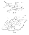
- Fig. 1 an example of an aircraft 10 is generically and generally schematically illustrated.
- Aircraft 10 may take any suitable form, including commercial aircraft, military aircraft, or any other suitable aircraft. While Fig. 1 illustrates an aircraft 10 in the form of a fixed wing aircraft, other types and configurations of aircraft are within the scope of the present disclosure.
- Aircraft 10 include airframes 12, which may define, or at least partially define, such illustrative, non-exclusive components as a fuselage 14, wings 16, vertical stabilizer 18, horizontal stabilizers 20, etc.
- Airframes 12 include a skin 22 that is operatively coupled to a series of structural reinforcement members 24.
- the skin 22 of an aircraft 10 at least partially defines the outer surface 26 of the aircraft 10.
- Skins 22 may be constructed of any suitable material including metals and composite materials.
- aluminum alloys and carbon fiber reinforced composite materials may be used to construct skins 22.
- a carbon fiber reinforced composite material should be understood to include at least an epoxy or other polymer or binding material together with carbon fibers.
- Other fibers (e.g., boron and Kevlar) other than carbon fibers also are within the scope of carbon fiber reinforced composite materials, as used herein.
- Carbon fiber reinforced composite materials additionally or alternatively may be described as or referred to as carbon fiber reinforced polymers.
- Structural reinforcement members 24 give stability to the skins 22 of an airframe 12 and provide a frame, on which the skin 22 is operatively coupled, such as illustrated somewhat schematically in Fig. 2 .
- Structural reinforcement members 24 may take any suitable form, and the fragmented example schematically represented in Fig. 2 does not limit the scope of structural reinforcement members 24 according to the present disclosure.
- structural reinforcement members 24 generally may have an I-shaped, H-shaped, T-shaped, L-shaped, or hat-shaped cross-sectional profile or any other suitable shape or shapes of cross-sectional profiles, depending on the particular region of the airframe 12 including a structural reinforcement member 24, depending on the specific application of the structural reinforcement member 24, etc.
- Structural reinforcement members are not required to have a uniform cross-sectional profile.
- Structural reinforcement members 24 additionally or alternatively may be described as or referred to as stiffeners 24, panel stiffeners 24, skin stiffeners 24, stringers 24, and/or frame members 24.
- Structural reinforcement members 24 may be described in terms of a longitudinal direction and a lateral direction, with the longitudinal direction referring to the longer dimension 28 of a structural reinforcement member 24, and with the lateral direction referring to the shorter dimension 30 of a structural reinforcement member.
- the longer dimension 28 additionally or alternatively may be described as or referred to as the longitudinal dimension 28 or as the length 28 of the structural reinforcement member 24, and the shorter dimension 30 additionally or alternatively may be described as or referred to as the lateral dimension 30 or as the width 30 of the structural reinforcement member 24.
- airframes 12 may be described in terms of relative relationships between such other aspects or components and a structural reinforcement member 24. Accordingly, an aspect or component that is described as extending longitudinally relative to a structural reinforcement member 24 is interpreted to extend in a direction that is parallel to the longitudinal dimension 28 of the structural reinforcement member 24, and an aspect or component that is described as extending laterally relative to a structural reinforcement member 24 is interpreted to extend in a direction that is parallel to the lateral dimension 30 of the structural reinforcement member 24.
- an aspect or component of an airframe 12 that is described as being longitudinally spaced away from another aspect or component of an airframe 12 is interpreted to be spaced away from such other aspect or component in a direction that is parallel to the longitudinal dimension 28 of the structural reinforcement member 24, and an aspect or component of an airframe 12 that is described as being laterally spaced away from another aspect or component of an airframe 12 is interpreted to be spaced away from such other aspect or component in a direction that is parallel to the lateral dimension 30 of the structural reinforcement member 24.
- structural reinforcement members 24 may include a base flange 32 and a leg 34 that extends from the base flange 32.
- the base flange 32 extends laterally on both sides of the leg 34; however, such a configuration is not required, and as discussed herein, other configurations of structural reinforcement members 24 are within the scope of the present disclosure.
- Structural reinforcement members 24 may be described as including a terminal end region 36 that includes a terminal edge 38 of the structural reinforcement member 24.
- the skin 22 is operatively coupled to the base flange 32 opposite the leg 34, and the skin 22 extends longitudinally beyond the terminal edge 38. That is, the skin 22 does not include a corresponding edge that coincides with the terminal edge 38 of the structural reinforcement member 24 that is illustrated in Fig. 2 .
- Airframes 12 according to the present disclosure include at least one such structural reinforcement member 24, whose terminal edge 38 does not coincide with a corresponding edge of the skin 22, or at least a portion thereof.
- the skin 22 and the structural reinforcement member 24 collectively define a run-out region 48 of the airframe 12, which encompasses the terminal end region 36 of the structural reinforcement member 24 and a portion of the skin 22 that is adjacent to the terminal end region 36.
- the skin 22 defines a region 39 that is more flexible than adjacent regions of the skin 22.
- a region 39 additionally or alternatively may be referred to or described as a region of increased flexibility 39 or region of increased transverse flexibility 39 relative to adjacent portions of the skin 22, or as a region of decreased stiffness 39 or region of decreased transverse stiffness 39 that is less stiff than adjacent regions of the skin 22.
- the flexibility and/or stiffness of the region 39 may be described in terms of a flexibility and/or stiffness in the direction of, or through, the thickness 41 of the skin 22.
- the region 39 may help to restrict or even prevent separation of the skin 22 from the structural reinforcement member 24 in the run-out region 48, when the run-out region 48 of the airframe 12 is under a bending stress, such as a tensile bending stress or a compressive bending stress.
- a bending stress such as a tensile bending stress or a compressive bending stress.
- the region of increased flexibility 39 may reduce the likelihood of or even prevent the separation of the adhesive between the skin 22 and the structural reinforcement member 24 within the run-out region 48.
- the region 39 may reduce the likelihood of or even prevent a separation of the adhesive between the skin 22 and the structural reinforcement member 24 within the run-out region 48 from propagating along the length 28 of the structural reinforcement member 24.
- the run-out region 48 of an airframe 12 may be described in terms of a size and/or position relative to the structural reinforcement member 24.
- the run-out region 48 may extend longitudinally relative to and extensive with the structural reinforcement member 24 from the terminal edge 38 for a longitudinal distance along the structural reinforcement member 24.
- a run-out region 48 may run from the terminal edge 38 along the structural reinforcement member 24 for a distance that is less than five times the lateral width 30, for a distance that is less than four times the lateral width 30, for a distance that is less than three times the lateral width 30, for a distance that is less than two times the lateral width 30, or for a distance that is less than the lateral width 30.
- the run-out region 48 also may extend longitudinally relative to and away from the structural reinforcement member 24.
- a run-out region 48 may extend longitudinally away from the structural reinforcement member 24 for a distance measured from the terminal edge 38 that is less than five times the lateral width 30, for a distance measured from the terminal edge 38 that is less than four times the lateral width 30, for a distance measured from the terminal edge 38 that is less than three times the lateral width 30, for a distance measured from the terminal edge 38 that is less than two times the lateral width 30, or for a distance measured from the terminal edge 38 that is less than the lateral width 30.
- the run-out region 48 may not extend the full longitudinal length 28 of the structural reinforcement member 24.
- the run-out region 48 additionally or alternatively may extend laterally relative to the structural reinforcement member 24.
- the run-out region 48 may extend laterally relative to the structural reinforcement member 24 for a distance that is less than the width 30.
- the region of increased flexibility 39 may include and/or define a region of reduced cross-sectional area 40.
- the region of reduced cross-sectional area 40 of the skin 22 additionally or alternatively may be referred to or described as a region of reduced volume 40 of the material from which the skin 22 is constructed.
- reduced it is meant that the region of reduced cross-sectional area 40 includes less volume of material from which the skin 22 is constructed relative to a similarly sized region of the skin 22 that is not a region of reduced cross-sectional area 40.
- the region of reduced cross-sectional area 40 may facilitate the increased flexibility and/or the decreased stiffness associated with the region of increased flexibility 39.
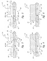
- the airframes 12 schematically represented in Figs. 3-7 include illustrative, non-exclusive examples of regions of reduced cross-sectional area 40.
- regions of reduced cross-sectional area 40 may be described as defining a void 42, and/or the skins 22 may be described as defining a void 42 within a region of reduced cross-sectional area 40.
- Figs. 3-4 illustrate examples of voids 42 that may be described as open voids 44, because the open voids 44 are not bound on all sides by the material from which the skin 22 is constructed. Figs.
- voids 42 that may be described as closed voids 46, because the closed voids 46 are bound on all sides by the material from which the skin 22 is constructed.
- An open void 44 additionally or alternatively may be described as a recess 44, and a closed void 46 additionally or alternatively may be described as a pocket 46.
- an open void 44 may face away from the structural reinforcement member 24. However, in some embodiments, as schematically and optionally illustrated in dash-dot lines in Fig. 3 , an open void 44 may face toward the structural reinforcement member 24.
- Figs. 3-6 schematically illustrate in solid lines the regions of reduced cross-sectional area 40 with generally rectangular boxes, this representation is schematic in nature and is interpreted to indicate that regions of reduced cross-sectional area 40 may have any suitable cross-sectional profiles.
- regions of reduced cross-sectional areas 40 and voids 42 may have cross-sectional profiles that have curved portions and/or that do not have sharp edges or corners.
- voids 42 may be free of sharp edges or corners.
- Fig. 7 schematically illustrates a plan view of an airframe 12, schematically illustrating non-exclusive examples of regions of reduced cross-sectional area 40.
- the region of reduced cross-sectional area 40 may be longitudinally aligned with the structural reinforcement member 24, including the leg 34 thereof.
- the region of reduced cross-sectional area 40 may extend adjacent to the terminal end region 36 of the structural reinforcement member 24.
- the region of reduced cross-sectional area 40 may extend longitudinally beyond the terminal end region 36.
- the skin 22 may be adhered to or co-bonded with the base flange 32 of the structural reinforcement member 24.
- suitable adhesives and resins include (but are not limited to) epoxies, unsaturated polyesters, polyetherkeytone, and other materials.
- the base flange 32 is adhered to the skin 22 within an entirety of the interface between the base flange 32 and the skin 22 within the run-out region 48. In some embodiments, the base flange 32 is adhered to the skin 22 within the run-out region 48. In some embodiments, the base flange 32 is adhered to the skin 22 within an entirety of the interface between the base flange 32 and the skin 22.
- the base flange 32 is not adhered to the skin 22 within at least a portion of the interface between the base flange 32 and the skin 22 within the run-out region 48. In some such embodiments, the portion of the interface between the base flange 32 and the skin 22 within the run-out region 48 in which adhesive is not used is aligned with and optionally is coextensive with the optional region of reduced cross-sectional area 40.
- an airframe 12 additionally or alternatively may include one or more fasteners 50 that extend through and that operatively couple, or at least assist in operatively coupling, the structural reinforcement member 24 and the skin 22.
- the optional fasteners 50 may be in addition to or as an alternative to the optional adhesive discussed herein.
- an airframe 12 may include one or more fasteners 50 that extend within the run-out region 48. Additionally or alternatively, in some embodiments, an airframe 12 may include at least one fastener 50 that is outside of and adjacent to the run-out region 48. Additionally or alternatively, in embodiments that include a region of reduced cross-sectional area 40, an airframe 12 may include at least one fastener 50 that is positioned laterally adjacent to the region of reduced cross-sectional area 40 within the run-out region 48.
- an airframe 12 may include at least one fastener 50 that is positioned laterally adjacent to the void 42. Additionally or alternatively, in embodiments that include a region of reduced cross-sectional area 40, an airframe 12 may include one or more fasteners 50 that do not extend through the region of reduced cross-sectional area 40. Additionally or alternatively, in embodiments that include a void 42, an airframe 12 may include one or more fasteners 50 that do not extend through the void 42. In some embodiments, an airframe 12 may be free of fasteners 50 that extend through the structural reinforcement member 24 and the skin 22 within the run-out region 48.
- airframes 12 optionally may include a splice plate 52 coupled to the skin 22 opposite the structural reinforcement member 24, including within the run-out region 48.
- Splice plates 52 when present, may be used to interconnect adjacent portions of an airframe 12.
- Methods 100 include defining a region of increased flexibility 39 of a skin 22, as indicated at 102, and operatively coupling the skin 22 to a structural reinforcement member 24, as indicated at 104.
- the operative coupling 104 includes positioning the region of increased flexibility 39 within the run-out region 48.
- the defining 102 includes defining the region of reduced cross-sectional area 40 of the skin 22.
- the defining 102 includes layering a plurality of layers 106 of carbon fiber reinforced composite material so that edges 108 of a subset of the layers 106 at least partially define a void 42 that defines the region of reduced cross-sectional area 40 of the skin 22. Examples of such skins 22 are schematically represented in Figs. 9-10 , with Fig. 9 representing an example that defines an open void 44 and with Fig. 10 representing an example that defines a closed void 46.
- the defining 102 may include molding carbon fiber reinforced composite material to form the skin.
- the molding may include utilizing a mold 110 that includes a protrusion 112 that defines an open void 44 in the skin 22.
- the molding may include molding carbon fiber reinforced composite material around an insert 114, and optionally a hollow insert 114, so that the insert 114 defines a closed void 46 within the skin 22.
- the coupling 104 may include adhering the skin 22 to the structural reinforcement member 24.
- the adhering may include adhering the skin 22 to the structural reinforcement member 24 within the run-out region 48. Additionally or alternatively, in some such methods, the adhering may include adhering the skin 22 to the structural reinforcement member 24 only within a portion of the interface between the structural reinforcement member 24 and the skin 22 within the run-out region 48. Additionally or alternatively, in some such methods, the adhering may include adhering the skin 22 to the structural reinforcement member 24 within an entirety of the interface between the structural reinforcement member 24 and the skin 22. In other of such methods, the adhering may not include adhering the skin 22 to the structural reinforcement member 24 within the run-out region 48.
- the coupling 104 additionally or alternatively may include fastening the structural reinforcement member 24 to the skin 22 with one or more fasteners 50 that extend through the structural reinforcement member 24 and the skin 22 outside of and adjacent to the run-out region 48.
- the coupling 104 additionally or alternatively may include fastening the structural reinforcement member 24 to the skin 22 with one or more fasteners 50 that extend through the structural reinforcement member 24 and the skin 22 within the run-out region 48.
- the one or more fasteners 50 may extend through the structural reinforcement member 24 and the skin 22 laterally adjacent to the region of reduced cross-sectional area 40.
Landscapes
- Engineering & Computer Science (AREA)
- Mechanical Engineering (AREA)
- Aviation & Aerospace Engineering (AREA)
- Moulding By Coating Moulds (AREA)
- Tires In General (AREA)
- Laminated Bodies (AREA)
Applications Claiming Priority (1)
| Application Number | Priority Date | Filing Date | Title |
|---|---|---|---|
| US13/480,918 US9180958B2 (en) | 2012-05-25 | 2012-05-25 | Aircraft, airframes and associated methods |
Publications (3)
| Publication Number | Publication Date |
|---|---|
| EP2666714A2 true EP2666714A2 (de) | 2013-11-27 |
| EP2666714A3 EP2666714A3 (de) | 2015-02-25 |
| EP2666714B1 EP2666714B1 (de) | 2017-02-15 |
Family
ID=48141733
Family Applications (1)
| Application Number | Title | Priority Date | Filing Date |
|---|---|---|---|
| EP13160610.5A Active EP2666714B1 (de) | 2012-05-25 | 2013-03-22 | Luftfahrzeug, Luftfahrzeugzelle und zugehörige Methoden |
Country Status (4)
| Country | Link |
|---|---|
| US (1) | US9180958B2 (de) |
| EP (1) | EP2666714B1 (de) |
| JP (1) | JP6215571B2 (de) |
| ES (1) | ES2624987T3 (de) |
Cited By (1)
| Publication number | Priority date | Publication date | Assignee | Title |
|---|---|---|---|---|
| US20240158068A1 (en) * | 2021-01-26 | 2024-05-16 | Airspace Experience Technologies Inc. | Method of manufacturing composite aircraft structures |
Families Citing this family (2)
| Publication number | Priority date | Publication date | Assignee | Title |
|---|---|---|---|---|
| US9708065B2 (en) | 2015-04-07 | 2017-07-18 | The Boeing Company | Crown cabin configuration for an aircraft |
| FI127614B (en) * | 2017-04-07 | 2018-10-15 | Patria Aerostructures Oy | COMPOSITE ELEMENT AND METHOD FOR MANUFACTURING IT |
Family Cites Families (28)
| Publication number | Priority date | Publication date | Assignee | Title |
|---|---|---|---|---|
| US2261558A (en) * | 1939-02-28 | 1941-11-04 | Orloff Benjamin | Fluid supported vehicle and method of producing the same |
| US4019699A (en) * | 1974-04-30 | 1977-04-26 | Teledyne Ryan Aeronautical A Division Of Teledyne Industries, Inc. | Aircraft of low observability |
| CH610069A5 (de) * | 1976-04-21 | 1979-03-30 | Rb Corp | |
| US4966802A (en) * | 1985-05-10 | 1990-10-30 | The Boeing Company | Composites made of fiber reinforced resin elements joined by adhesive |
| DE3614618A1 (de) * | 1986-04-30 | 1987-11-05 | Messerschmitt Boelkow Blohm | Schalenstruktur aus faserverstaerktem kunststoff |
| US4861643A (en) * | 1987-03-13 | 1989-08-29 | The Boeing Company | Aerospace structure having a cast-in-place noncompressible void filler |
| US4858853A (en) * | 1988-02-17 | 1989-08-22 | The Boeing Company | Bolted repair for curved surfaces |
| US5171623A (en) * | 1990-12-27 | 1992-12-15 | Yee Norman D | Drag reducing surface depressions |
| US5378524A (en) * | 1991-05-28 | 1995-01-03 | Blood; Charles L. | Friction reducing surface and devices employing such surfaces |
| US5518208A (en) * | 1993-12-28 | 1996-05-21 | The Boeing Company | Optimum aircraft body frame to body skin shear tie installation pattern for body skin/stringer circumferential splices |
| US6638466B1 (en) | 2000-12-28 | 2003-10-28 | Raytheon Aircraft Company | Methods of manufacturing separable structures |
| WO2002081210A1 (en) | 2001-04-06 | 2002-10-17 | Marion Composites, A Division Of Advanced Technical Products, Inc. | Method of manufacturing a hollow section, grid stiffened panel |
| ES2213422B1 (es) * | 2001-07-23 | 2005-06-01 | Gamesa Desarrollos Aeronatuticos, S.A. | Placa cortafuegos para tapar motores de aeronaves. |
| US7197852B2 (en) * | 2002-09-20 | 2007-04-03 | The Boeing Company | Internally stiffened composite panels and methods for their manufacture |
| US8104158B2 (en) * | 2004-08-26 | 2012-01-31 | The Boeing Company | Detecting and reworking inconsistencies proximate aircraft splice joints |
| US7837147B2 (en) * | 2005-03-18 | 2010-11-23 | The Boeing Company | Systems and methods for reducing noise in aircraft fuselages and other structures |
| US20060248854A1 (en) * | 2005-05-05 | 2006-11-09 | Bartley-Cho Jonathan D | Thermally insulated structure - tapered joint concept |
| DE102005026010B4 (de) * | 2005-06-07 | 2010-12-30 | Airbus Deutschland Gmbh | Verfahren zur Herstellung einer verstärkten Schale zur Bildung von Teilkomponenten für Luftfahrzeuge |
| US7871040B2 (en) * | 2006-11-10 | 2011-01-18 | The Boeing Company | Composite aircraft structures with hat stiffeners |
| US7635106B2 (en) * | 2006-11-30 | 2009-12-22 | The Boeing Company | Composite shear tie |
| GB0708333D0 (en) * | 2007-04-30 | 2007-06-06 | Airbus Uk Ltd | Composite structure |
| US7861969B2 (en) * | 2007-05-24 | 2011-01-04 | The Boeing Company | Shaped composite stringers and methods of making |
| US7851048B2 (en) * | 2008-02-12 | 2010-12-14 | Milliken & Co. | Fiber reinforced core panel |
| US8128025B2 (en) * | 2008-03-21 | 2012-03-06 | The Boeing Company | Providing skins for aircraft fuselages |
| GB0819159D0 (en) | 2008-10-20 | 2008-11-26 | Airbus Uk Ltd | Joint between aircraft components |
| US8316544B2 (en) * | 2009-06-01 | 2012-11-27 | Lockheed Martin Corporation | Expandable precured joint filler |
| US8282042B2 (en) * | 2009-06-22 | 2012-10-09 | The Boeing Company | Skin panel joint for improved airflow |
| DE102010013370B8 (de) * | 2010-03-30 | 2013-12-12 | Eads Deutschland Gmbh | Wandbauteil für ein Luftfahrzeug |
-
2012
- 2012-05-25 US US13/480,918 patent/US9180958B2/en active Active
-
2013
- 2013-03-22 ES ES13160610.5T patent/ES2624987T3/es active Active
- 2013-03-22 EP EP13160610.5A patent/EP2666714B1/de active Active
- 2013-05-21 JP JP2013106894A patent/JP6215571B2/ja active Active
Non-Patent Citations (1)
| Title |
|---|
| None |
Cited By (2)
| Publication number | Priority date | Publication date | Assignee | Title |
|---|---|---|---|---|
| US20240158068A1 (en) * | 2021-01-26 | 2024-05-16 | Airspace Experience Technologies Inc. | Method of manufacturing composite aircraft structures |
| US12358607B2 (en) * | 2021-01-26 | 2025-07-15 | Airspace Experience Technologies, Inc. (ASX) | Method of manufacturing composite aircraft structures |
Also Published As
| Publication number | Publication date |
|---|---|
| ES2624987T3 (es) | 2017-07-18 |
| EP2666714A3 (de) | 2015-02-25 |
| US9180958B2 (en) | 2015-11-10 |
| JP2013244960A (ja) | 2013-12-09 |
| EP2666714B1 (de) | 2017-02-15 |
| US20130313368A1 (en) | 2013-11-28 |
| JP6215571B2 (ja) | 2017-10-18 |
Similar Documents
| Publication | Publication Date | Title |
|---|---|---|
| US10308345B2 (en) | Structure | |
| KR101513845B1 (ko) | 패널의 리세스에 삽입된 패드를 갖는 스트링거를 포함하는 복합 구조체 및 힘 전달 방법 | |
| JP6930876B2 (ja) | 航空機翼及び当該航空機翼を含む航空機 | |
| JP5808111B2 (ja) | 航空機用複合材構造体、これを備えた航空機主翼および航空機胴体 | |
| US9862477B2 (en) | Aircraft structure | |
| US8985512B1 (en) | Aircraft, fuselages, and associated methods | |
| EP3029339B1 (de) | Verbindung und luftfahrzeugstruktur | |
| US20170001707A1 (en) | Upper joints between outboard wing boxes and wing center sections of aircraft wing assemblies | |
| US9227718B2 (en) | Lower joints between outboard wing boxes and center wing sections of aircraft wing assemblies | |
| EP3015721B1 (de) | Verbindung und luftfahrzeugstruktur | |
| US8434719B2 (en) | Leading edge element of aircraft, method for manufacturing one, wing and stabilizer | |
| EP2671795B1 (de) | Verbundmaterialstruktur und flugzeugflügel damit | |
| WO2013133880A1 (en) | Bonded splice joint | |
| JP2012162147A5 (de) | ||
| JP7202194B2 (ja) | 共通の基礎支持部を通るストリンガ移行部 | |
| US9180958B2 (en) | Aircraft, airframes and associated methods | |
| EP2977313A1 (de) | Rippenfuss | |
| EP3530452B1 (de) | Verbundstrukturelement | |
| US20200130807A1 (en) | Primary structural element | |
| CN102756480A (zh) | 一种用于复合材料壁板的ω型的加强筋 | |
| US11518495B2 (en) | Composite structural elements | |
| CN214566116U (zh) | 一种飞机整体翼面壁板结构 |
Legal Events
| Date | Code | Title | Description |
|---|---|---|---|
| PUAI | Public reference made under article 153(3) epc to a published international application that has entered the european phase |
Free format text: ORIGINAL CODE: 0009012 |
|
| AK | Designated contracting states |
Kind code of ref document: A2 Designated state(s): AL AT BE BG CH CY CZ DE DK EE ES FI FR GB GR HR HU IE IS IT LI LT LU LV MC MK MT NL NO PL PT RO RS SE SI SK SM TR |
|
| AX | Request for extension of the european patent |
Extension state: BA ME |
|
| PUAL | Search report despatched |
Free format text: ORIGINAL CODE: 0009013 |
|
| AK | Designated contracting states |
Kind code of ref document: A3 Designated state(s): AL AT BE BG CH CY CZ DE DK EE ES FI FR GB GR HR HU IE IS IT LI LT LU LV MC MK MT NL NO PL PT RO RS SE SI SK SM TR |
|
| AX | Request for extension of the european patent |
Extension state: BA ME |
|
| RIC1 | Information provided on ipc code assigned before grant |
Ipc: B64C 1/00 20060101ALI20150119BHEP Ipc: B64C 1/12 20060101ALI20150119BHEP Ipc: B64C 1/06 20060101AFI20150119BHEP |
|
| 17P | Request for examination filed |
Effective date: 20150821 |
|
| RBV | Designated contracting states (corrected) |
Designated state(s): AL AT BE BG CH CY CZ DE DK EE ES FI FR GB GR HR HU IE IS IT LI LT LU LV MC MK MT NL NO PL PT RO RS SE SI SK SM TR |
|
| GRAP | Despatch of communication of intention to grant a patent |
Free format text: ORIGINAL CODE: EPIDOSNIGR1 |
|
| RIC1 | Information provided on ipc code assigned before grant |
Ipc: B64C 1/06 20060101AFI20160114BHEP Ipc: B64C 1/00 20060101ALI20160114BHEP Ipc: B64C 1/12 20060101ALI20160114BHEP |
|
| INTG | Intention to grant announced |
Effective date: 20160210 |
|
| 17Q | First examination report despatched |
Effective date: 20160405 |
|
| INTC | Intention to grant announced (deleted) | ||
| GRAP | Despatch of communication of intention to grant a patent |
Free format text: ORIGINAL CODE: EPIDOSNIGR1 |
|
| INTG | Intention to grant announced |
Effective date: 20160908 |
|
| GRAS | Grant fee paid |
Free format text: ORIGINAL CODE: EPIDOSNIGR3 |
|
| GRAA | (expected) grant |
Free format text: ORIGINAL CODE: 0009210 |
|
| AK | Designated contracting states |
Kind code of ref document: B1 Designated state(s): AL AT BE BG CH CY CZ DE DK EE ES FI FR GB GR HR HU IE IS IT LI LT LU LV MC MK MT NL NO PL PT RO RS SE SI SK SM TR |
|
| REG | Reference to a national code |
Ref country code: CH Ref legal event code: EP Ref country code: GB Ref legal event code: FG4D |
|
| REG | Reference to a national code |
Ref country code: IE Ref legal event code: FG4D |
|
| REG | Reference to a national code |
Ref country code: AT Ref legal event code: REF Ref document number: 867728 Country of ref document: AT Kind code of ref document: T Effective date: 20170315 |
|
| REG | Reference to a national code |
Ref country code: FR Ref legal event code: PLFP Year of fee payment: 5 |
|
| REG | Reference to a national code |
Ref country code: DE Ref legal event code: R096 Ref document number: 602013017428 Country of ref document: DE |
|
| REG | Reference to a national code |
Ref country code: NL Ref legal event code: MP Effective date: 20170215 |
|
| REG | Reference to a national code |
Ref country code: LT Ref legal event code: MG4D |
|
| REG | Reference to a national code |
Ref country code: AT Ref legal event code: MK05 Ref document number: 867728 Country of ref document: AT Kind code of ref document: T Effective date: 20170215 |
|
| REG | Reference to a national code |
Ref country code: ES Ref legal event code: FG2A Ref document number: 2624987 Country of ref document: ES Kind code of ref document: T3 Effective date: 20170718 |
|
| PG25 | Lapsed in a contracting state [announced via postgrant information from national office to epo] |
Ref country code: LT Free format text: LAPSE BECAUSE OF FAILURE TO SUBMIT A TRANSLATION OF THE DESCRIPTION OR TO PAY THE FEE WITHIN THE PRESCRIBED TIME-LIMIT Effective date: 20170215 Ref country code: GR Free format text: LAPSE BECAUSE OF FAILURE TO SUBMIT A TRANSLATION OF THE DESCRIPTION OR TO PAY THE FEE WITHIN THE PRESCRIBED TIME-LIMIT Effective date: 20170516 Ref country code: HR Free format text: LAPSE BECAUSE OF FAILURE TO SUBMIT A TRANSLATION OF THE DESCRIPTION OR TO PAY THE FEE WITHIN THE PRESCRIBED TIME-LIMIT Effective date: 20170215 Ref country code: NO Free format text: LAPSE BECAUSE OF FAILURE TO SUBMIT A TRANSLATION OF THE DESCRIPTION OR TO PAY THE FEE WITHIN THE PRESCRIBED TIME-LIMIT Effective date: 20170515 Ref country code: FI Free format text: LAPSE BECAUSE OF FAILURE TO SUBMIT A TRANSLATION OF THE DESCRIPTION OR TO PAY THE FEE WITHIN THE PRESCRIBED TIME-LIMIT Effective date: 20170215 |
|
| PG25 | Lapsed in a contracting state [announced via postgrant information from national office to epo] |
Ref country code: RS Free format text: LAPSE BECAUSE OF FAILURE TO SUBMIT A TRANSLATION OF THE DESCRIPTION OR TO PAY THE FEE WITHIN THE PRESCRIBED TIME-LIMIT Effective date: 20170215 Ref country code: AT Free format text: LAPSE BECAUSE OF FAILURE TO SUBMIT A TRANSLATION OF THE DESCRIPTION OR TO PAY THE FEE WITHIN THE PRESCRIBED TIME-LIMIT Effective date: 20170215 Ref country code: PT Free format text: LAPSE BECAUSE OF FAILURE TO SUBMIT A TRANSLATION OF THE DESCRIPTION OR TO PAY THE FEE WITHIN THE PRESCRIBED TIME-LIMIT Effective date: 20170615 Ref country code: SE Free format text: LAPSE BECAUSE OF FAILURE TO SUBMIT A TRANSLATION OF THE DESCRIPTION OR TO PAY THE FEE WITHIN THE PRESCRIBED TIME-LIMIT Effective date: 20170215 Ref country code: LV Free format text: LAPSE BECAUSE OF FAILURE TO SUBMIT A TRANSLATION OF THE DESCRIPTION OR TO PAY THE FEE WITHIN THE PRESCRIBED TIME-LIMIT Effective date: 20170215 Ref country code: NL Free format text: LAPSE BECAUSE OF FAILURE TO SUBMIT A TRANSLATION OF THE DESCRIPTION OR TO PAY THE FEE WITHIN THE PRESCRIBED TIME-LIMIT Effective date: 20170215 Ref country code: BG Free format text: LAPSE BECAUSE OF FAILURE TO SUBMIT A TRANSLATION OF THE DESCRIPTION OR TO PAY THE FEE WITHIN THE PRESCRIBED TIME-LIMIT Effective date: 20170515 |
|
| PG25 | Lapsed in a contracting state [announced via postgrant information from national office to epo] |
Ref country code: EE Free format text: LAPSE BECAUSE OF FAILURE TO SUBMIT A TRANSLATION OF THE DESCRIPTION OR TO PAY THE FEE WITHIN THE PRESCRIBED TIME-LIMIT Effective date: 20170215 Ref country code: CZ Free format text: LAPSE BECAUSE OF FAILURE TO SUBMIT A TRANSLATION OF THE DESCRIPTION OR TO PAY THE FEE WITHIN THE PRESCRIBED TIME-LIMIT Effective date: 20170215 Ref country code: RO Free format text: LAPSE BECAUSE OF FAILURE TO SUBMIT A TRANSLATION OF THE DESCRIPTION OR TO PAY THE FEE WITHIN THE PRESCRIBED TIME-LIMIT Effective date: 20170215 Ref country code: IT Free format text: LAPSE BECAUSE OF FAILURE TO SUBMIT A TRANSLATION OF THE DESCRIPTION OR TO PAY THE FEE WITHIN THE PRESCRIBED TIME-LIMIT Effective date: 20170215 Ref country code: SK Free format text: LAPSE BECAUSE OF FAILURE TO SUBMIT A TRANSLATION OF THE DESCRIPTION OR TO PAY THE FEE WITHIN THE PRESCRIBED TIME-LIMIT Effective date: 20170215 |
|
| REG | Reference to a national code |
Ref country code: CH Ref legal event code: PL |
|
| REG | Reference to a national code |
Ref country code: DE Ref legal event code: R097 Ref document number: 602013017428 Country of ref document: DE |
|
| PG25 | Lapsed in a contracting state [announced via postgrant information from national office to epo] |
Ref country code: DK Free format text: LAPSE BECAUSE OF FAILURE TO SUBMIT A TRANSLATION OF THE DESCRIPTION OR TO PAY THE FEE WITHIN THE PRESCRIBED TIME-LIMIT Effective date: 20170215 Ref country code: MC Free format text: LAPSE BECAUSE OF FAILURE TO SUBMIT A TRANSLATION OF THE DESCRIPTION OR TO PAY THE FEE WITHIN THE PRESCRIBED TIME-LIMIT Effective date: 20170215 Ref country code: SM Free format text: LAPSE BECAUSE OF FAILURE TO SUBMIT A TRANSLATION OF THE DESCRIPTION OR TO PAY THE FEE WITHIN THE PRESCRIBED TIME-LIMIT Effective date: 20170215 Ref country code: PL Free format text: LAPSE BECAUSE OF FAILURE TO SUBMIT A TRANSLATION OF THE DESCRIPTION OR TO PAY THE FEE WITHIN THE PRESCRIBED TIME-LIMIT Effective date: 20170215 |
|
| PLBE | No opposition filed within time limit |
Free format text: ORIGINAL CODE: 0009261 |
|
| STAA | Information on the status of an ep patent application or granted ep patent |
Free format text: STATUS: NO OPPOSITION FILED WITHIN TIME LIMIT |
|
| REG | Reference to a national code |
Ref country code: IE Ref legal event code: MM4A |
|
| 26N | No opposition filed |
Effective date: 20171116 |
|
| PG25 | Lapsed in a contracting state [announced via postgrant information from national office to epo] |
Ref country code: LU Free format text: LAPSE BECAUSE OF NON-PAYMENT OF DUE FEES Effective date: 20170322 |
|
| PG25 | Lapsed in a contracting state [announced via postgrant information from national office to epo] |
Ref country code: CH Free format text: LAPSE BECAUSE OF NON-PAYMENT OF DUE FEES Effective date: 20170331 Ref country code: LI Free format text: LAPSE BECAUSE OF NON-PAYMENT OF DUE FEES Effective date: 20170331 Ref country code: IE Free format text: LAPSE BECAUSE OF NON-PAYMENT OF DUE FEES Effective date: 20170322 Ref country code: SI Free format text: LAPSE BECAUSE OF FAILURE TO SUBMIT A TRANSLATION OF THE DESCRIPTION OR TO PAY THE FEE WITHIN THE PRESCRIBED TIME-LIMIT Effective date: 20170215 |
|
| REG | Reference to a national code |
Ref country code: BE Ref legal event code: MM Effective date: 20170331 |
|
| REG | Reference to a national code |
Ref country code: FR Ref legal event code: PLFP Year of fee payment: 6 |
|
| PG25 | Lapsed in a contracting state [announced via postgrant information from national office to epo] |
Ref country code: BE Free format text: LAPSE BECAUSE OF NON-PAYMENT OF DUE FEES Effective date: 20170331 |
|
| PG25 | Lapsed in a contracting state [announced via postgrant information from national office to epo] |
Ref country code: MT Free format text: LAPSE BECAUSE OF NON-PAYMENT OF DUE FEES Effective date: 20170322 |
|
| PG25 | Lapsed in a contracting state [announced via postgrant information from national office to epo] |
Ref country code: HU Free format text: LAPSE BECAUSE OF FAILURE TO SUBMIT A TRANSLATION OF THE DESCRIPTION OR TO PAY THE FEE WITHIN THE PRESCRIBED TIME-LIMIT; INVALID AB INITIO Effective date: 20130322 |
|
| PG25 | Lapsed in a contracting state [announced via postgrant information from national office to epo] |
Ref country code: CY Free format text: LAPSE BECAUSE OF NON-PAYMENT OF DUE FEES Effective date: 20170215 |
|
| PG25 | Lapsed in a contracting state [announced via postgrant information from national office to epo] |
Ref country code: MK Free format text: LAPSE BECAUSE OF FAILURE TO SUBMIT A TRANSLATION OF THE DESCRIPTION OR TO PAY THE FEE WITHIN THE PRESCRIBED TIME-LIMIT Effective date: 20170215 |
|
| PG25 | Lapsed in a contracting state [announced via postgrant information from national office to epo] |
Ref country code: TR Free format text: LAPSE BECAUSE OF FAILURE TO SUBMIT A TRANSLATION OF THE DESCRIPTION OR TO PAY THE FEE WITHIN THE PRESCRIBED TIME-LIMIT Effective date: 20170215 |
|
| PG25 | Lapsed in a contracting state [announced via postgrant information from national office to epo] |
Ref country code: AL Free format text: LAPSE BECAUSE OF FAILURE TO SUBMIT A TRANSLATION OF THE DESCRIPTION OR TO PAY THE FEE WITHIN THE PRESCRIBED TIME-LIMIT Effective date: 20170215 Ref country code: IS Free format text: LAPSE BECAUSE OF FAILURE TO SUBMIT A TRANSLATION OF THE DESCRIPTION OR TO PAY THE FEE WITHIN THE PRESCRIBED TIME-LIMIT Effective date: 20170615 |
|
| P01 | Opt-out of the competence of the unified patent court (upc) registered |
Effective date: 20230516 |
|
| PGFP | Annual fee paid to national office [announced via postgrant information from national office to epo] |
Ref country code: GB Payment date: 20260327 Year of fee payment: 14 |
|
| PGFP | Annual fee paid to national office [announced via postgrant information from national office to epo] |
Ref country code: DE Payment date: 20260327 Year of fee payment: 14 |
|
| PGFP | Annual fee paid to national office [announced via postgrant information from national office to epo] |
Ref country code: FR Payment date: 20260325 Year of fee payment: 14 |
|
| PGFP | Annual fee paid to national office [announced via postgrant information from national office to epo] |
Ref country code: ES Payment date: 20260401 Year of fee payment: 14 |