EP2666620A1 - Plastics optical component and method for manufacturing the same - Google Patents
Plastics optical component and method for manufacturing the same Download PDFInfo
- Publication number
- EP2666620A1 EP2666620A1 EP13166173.8A EP13166173A EP2666620A1 EP 2666620 A1 EP2666620 A1 EP 2666620A1 EP 13166173 A EP13166173 A EP 13166173A EP 2666620 A1 EP2666620 A1 EP 2666620A1
- Authority
- EP
- European Patent Office
- Prior art keywords
- plastic
- optical component
- base member
- covering
- plastic optical
- Prior art date
- Legal status (The legal status is an assumption and is not a legal conclusion. Google has not performed a legal analysis and makes no representation as to the accuracy of the status listed.)
- Granted
Links
Images




Classifications
-
- G—PHYSICS
- G02—OPTICS
- G02B—OPTICAL ELEMENTS, SYSTEMS OR APPARATUS
- G02B1/00—Optical elements characterised by the material of which they are made; Optical coatings for optical elements
- G02B1/04—Optical elements characterised by the material of which they are made; Optical coatings for optical elements made of organic materials, e.g. plastics
- G02B1/041—Lenses
-
- B—PERFORMING OPERATIONS; TRANSPORTING
- B29—WORKING OF PLASTICS; WORKING OF SUBSTANCES IN A PLASTIC STATE IN GENERAL
- B29C—SHAPING OR JOINING OF PLASTICS; SHAPING OF MATERIAL IN A PLASTIC STATE, NOT OTHERWISE PROVIDED FOR; AFTER-TREATMENT OF THE SHAPED PRODUCTS, e.g. REPAIRING
- B29C45/00—Injection moulding, i.e. forcing the required volume of moulding material through a nozzle into a closed mould; Apparatus therefor
- B29C45/16—Making multilayered or multicoloured articles
-
- B—PERFORMING OPERATIONS; TRANSPORTING
- B29—WORKING OF PLASTICS; WORKING OF SUBSTANCES IN A PLASTIC STATE IN GENERAL
- B29D—PRODUCING PARTICULAR ARTICLES FROM PLASTICS OR FROM SUBSTANCES IN A PLASTIC STATE
- B29D11/00—Producing optical elements, e.g. lenses or prisms
- B29D11/00009—Production of simple or compound lenses
-
- B—PERFORMING OPERATIONS; TRANSPORTING
- B29—WORKING OF PLASTICS; WORKING OF SUBSTANCES IN A PLASTIC STATE IN GENERAL
- B29D—PRODUCING PARTICULAR ARTICLES FROM PLASTICS OR FROM SUBSTANCES IN A PLASTIC STATE
- B29D11/00—Producing optical elements, e.g. lenses or prisms
- B29D11/00009—Production of simple or compound lenses
- B29D11/00038—Production of contact lenses
- B29D11/00048—Production of contact lenses composed of parts with dissimilar composition
-
- B—PERFORMING OPERATIONS; TRANSPORTING
- B29—WORKING OF PLASTICS; WORKING OF SUBSTANCES IN A PLASTIC STATE IN GENERAL
- B29D—PRODUCING PARTICULAR ARTICLES FROM PLASTICS OR FROM SUBSTANCES IN A PLASTIC STATE
- B29D11/00—Producing optical elements, e.g. lenses or prisms
- B29D11/0073—Optical laminates
-
- G—PHYSICS
- G02—OPTICS
- G02B—OPTICAL ELEMENTS, SYSTEMS OR APPARATUS
- G02B27/00—Optical systems or apparatus not provided for by any of the groups G02B1/00 - G02B26/00, G02B30/00
-
- B—PERFORMING OPERATIONS; TRANSPORTING
- B29—WORKING OF PLASTICS; WORKING OF SUBSTANCES IN A PLASTIC STATE IN GENERAL
- B29C—SHAPING OR JOINING OF PLASTICS; SHAPING OF MATERIAL IN A PLASTIC STATE, NOT OTHERWISE PROVIDED FOR; AFTER-TREATMENT OF THE SHAPED PRODUCTS, e.g. REPAIRING
- B29C45/00—Injection moulding, i.e. forcing the required volume of moulding material through a nozzle into a closed mould; Apparatus therefor
- B29C45/16—Making multilayered or multicoloured articles
- B29C45/1676—Making multilayered or multicoloured articles using a soft material and a rigid material, e.g. making articles with a sealing part
-
- B—PERFORMING OPERATIONS; TRANSPORTING
- B29—WORKING OF PLASTICS; WORKING OF SUBSTANCES IN A PLASTIC STATE IN GENERAL
- B29C—SHAPING OR JOINING OF PLASTICS; SHAPING OF MATERIAL IN A PLASTIC STATE, NOT OTHERWISE PROVIDED FOR; AFTER-TREATMENT OF THE SHAPED PRODUCTS, e.g. REPAIRING
- B29C45/00—Injection moulding, i.e. forcing the required volume of moulding material through a nozzle into a closed mould; Apparatus therefor
- B29C45/17—Component parts, details or accessories; Auxiliary operations
- B29C45/26—Moulds
- B29C45/27—Sprue channels ; Runner channels or runner nozzles
- B29C45/2701—Details not specific to hot or cold runner channels
- B29C45/2708—Gates
-
- B—PERFORMING OPERATIONS; TRANSPORTING
- B29—WORKING OF PLASTICS; WORKING OF SUBSTANCES IN A PLASTIC STATE IN GENERAL
- B29K—INDEXING SCHEME ASSOCIATED WITH SUBCLASSES B29B, B29C OR B29D, RELATING TO MOULDING MATERIALS OR TO MATERIALS FOR MOULDS, REINFORCEMENTS, FILLERS OR PREFORMED PARTS, e.g. INSERTS
- B29K2025/00—Use of polymers of vinyl-aromatic compounds or derivatives thereof as moulding material
- B29K2025/04—Polymers of styrene
- B29K2025/06—PS, i.e. polystyrene
-
- B—PERFORMING OPERATIONS; TRANSPORTING
- B29—WORKING OF PLASTICS; WORKING OF SUBSTANCES IN A PLASTIC STATE IN GENERAL
- B29K—INDEXING SCHEME ASSOCIATED WITH SUBCLASSES B29B, B29C OR B29D, RELATING TO MOULDING MATERIALS OR TO MATERIALS FOR MOULDS, REINFORCEMENTS, FILLERS OR PREFORMED PARTS, e.g. INSERTS
- B29K2033/00—Use of polymers of unsaturated acids or derivatives thereof as moulding material
- B29K2033/04—Polymers of esters
- B29K2033/12—Polymers of methacrylic acid esters, e.g. PMMA, i.e. polymethylmethacrylate
-
- B—PERFORMING OPERATIONS; TRANSPORTING
- B29—WORKING OF PLASTICS; WORKING OF SUBSTANCES IN A PLASTIC STATE IN GENERAL
- B29K—INDEXING SCHEME ASSOCIATED WITH SUBCLASSES B29B, B29C OR B29D, RELATING TO MOULDING MATERIALS OR TO MATERIALS FOR MOULDS, REINFORCEMENTS, FILLERS OR PREFORMED PARTS, e.g. INSERTS
- B29K2069/00—Use of PC, i.e. polycarbonates or derivatives thereof, as moulding material
-
- B—PERFORMING OPERATIONS; TRANSPORTING
- B29—WORKING OF PLASTICS; WORKING OF SUBSTANCES IN A PLASTIC STATE IN GENERAL
- B29K—INDEXING SCHEME ASSOCIATED WITH SUBCLASSES B29B, B29C OR B29D, RELATING TO MOULDING MATERIALS OR TO MATERIALS FOR MOULDS, REINFORCEMENTS, FILLERS OR PREFORMED PARTS, e.g. INSERTS
- B29K2995/00—Properties of moulding materials, reinforcements, fillers, preformed parts or moulds
- B29K2995/0037—Other properties
- B29K2995/0068—Permeability to liquids; Adsorption
- B29K2995/0069—Permeability to liquids; Adsorption non-permeable
-
- B—PERFORMING OPERATIONS; TRANSPORTING
- B29—WORKING OF PLASTICS; WORKING OF SUBSTANCES IN A PLASTIC STATE IN GENERAL
- B29K—INDEXING SCHEME ASSOCIATED WITH SUBCLASSES B29B, B29C OR B29D, RELATING TO MOULDING MATERIALS OR TO MATERIALS FOR MOULDS, REINFORCEMENTS, FILLERS OR PREFORMED PARTS, e.g. INSERTS
- B29K2995/00—Properties of moulding materials, reinforcements, fillers, preformed parts or moulds
- B29K2995/0037—Other properties
- B29K2995/007—Hardness
-
- Y—GENERAL TAGGING OF NEW TECHNOLOGICAL DEVELOPMENTS; GENERAL TAGGING OF CROSS-SECTIONAL TECHNOLOGIES SPANNING OVER SEVERAL SECTIONS OF THE IPC; TECHNICAL SUBJECTS COVERED BY FORMER USPC CROSS-REFERENCE ART COLLECTIONS [XRACs] AND DIGESTS
- Y10—TECHNICAL SUBJECTS COVERED BY FORMER USPC
- Y10T—TECHNICAL SUBJECTS COVERED BY FORMER US CLASSIFICATION
- Y10T428/00—Stock material or miscellaneous articles
- Y10T428/24—Structurally defined web or sheet [e.g., overall dimension, etc.]
- Y10T428/24479—Structurally defined web or sheet [e.g., overall dimension, etc.] including variation in thickness
- Y10T428/24521—Structurally defined web or sheet [e.g., overall dimension, etc.] including variation in thickness with component conforming to contour of nonplanar surface
-
- Y—GENERAL TAGGING OF NEW TECHNOLOGICAL DEVELOPMENTS; GENERAL TAGGING OF CROSS-SECTIONAL TECHNOLOGIES SPANNING OVER SEVERAL SECTIONS OF THE IPC; TECHNICAL SUBJECTS COVERED BY FORMER USPC CROSS-REFERENCE ART COLLECTIONS [XRACs] AND DIGESTS
- Y10—TECHNICAL SUBJECTS COVERED BY FORMER USPC
- Y10T—TECHNICAL SUBJECTS COVERED BY FORMER US CLASSIFICATION
- Y10T428/00—Stock material or miscellaneous articles
- Y10T428/24—Structurally defined web or sheet [e.g., overall dimension, etc.]
- Y10T428/24942—Structurally defined web or sheet [e.g., overall dimension, etc.] including components having same physical characteristic in differing degree
- Y10T428/24983—Hardness
Definitions
- the present invention relates to a plastic optical component used in optical apparatuses such as digital cameras and copy machines, and to a method for manufacturing the plastic optical component.
- Japanese Patent Laid-Open No. 8-187793 proposes that a base member be integrated with plastic covering portions so that first and second surfaces of the base member are covered with the covering portions.
- a thick plastic optical component must allow for a deformation resulting from the moisture absorption of the plastic thereof, and is accordingly formed of a plastic whose water absorption is low small. Otherwise, the surface of the optical component is likely to be deformed by moisture absorption and, consequently, the focus position may be displaced or other optical properties may be degraded.
- the surface hardnesses of low-water-absorption plastics used for injection molding are generally low. Thus, low-water-absorption plastics may not be able to satisfy the abrasion resistance required for use for an exposed portion of a digital camera. In use in a copy machine, a thick plastic optical component may be damaged during manufacture or maintenance. Even the above-cited Japanese Patent Laid-Open No. 8-187793 cannot solve this issue because the base member and the plastic covering member are made of the same material.
- the present invention provides a thick abrasion-resistant plastic optical component that is not much deformed by moisture absorption, and provides a method for manufacturing the plastic optical component.
- the present invention in its first aspect provides a plastic optical component as specified in claims 1 to 13.
- the present invention in its second aspect provides a method for manufacturing a plastic optical component as specified in claims 14 to 18.
- Fig. 1 is a representation of a plastic optical component according to a first embodiment of the present invention.
- Figs. 2A and 2B are representations of the plastic optical component of the first embodiment.
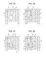
- Figs. 3A to 3D are representations of dies used in the first embodiment.
- Figs. 4A to 4D are representations of dies used in the first embodiment.
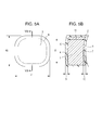
- Figs. 5A and 5B are representations of a plastic optical component prepared in an Example of the present invention.
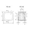
- Figs. 6A and 6B are representations of a plastic optical component prepared in an Example of the present invention.
- Figs. 7A and 7B are representations of a plastic optical component according to a second embodiment of the present invention.
- Figs. 8A and 8B are representations of a plastic optical component according to a third embodiment of the present invention.
- Figs. 9A to 9D are representations of dies used in an embodiment of the present invention.
- Figs. 10A to 10C are representations of a plastic optical component prepared in an Example of the present invention.
- Figs. 11A to 11C are representations of exemplary base members made of a first plastic, according to a fourth embodiment of the present invention.
- Figs. 12A to 12C are representations of a plastic optical component according to the fourth embodiment of the present invention.
- Fig. 1 is a sectional view of a plastic optical component 3 according to a first embodiment of the present invention.
- the plastic optical component 3 includes a base member 1 made of a first plastic, and a covering member 2 made of a second plastic.
- the base member 1 has a first surface 4 and a second surface 5.
- the plastic optical component 3 has a first surface 6 and a second surface 7.
- the first plastic of the base member 1 has a lower water absorption than the second plastic of the covering member 2.
- the second plastic has a higher hardness than the first plastic.
- the base member 1 may be a lens.
- the hardness of a plastic mentioned herein refers a pencil hardness measured in accordance with JIS K5401, and "a hard plastic" means the plastic has a high pencil hardness.
- a hard plastic means the plastic has a high pencil hardness.
- One of the surfaces 4 and 5 of the base member 1 is a first surface, and the other is a second surface. Either can be the first or second surface without particular limitation.
- one of the surfaces 6 and 7 of the plastic optical component 3 is a first surface, and the other is a second surface. Either can be the first or second surface without particular limitation.
- the base member 1 is a lens
- the lens may be a meniscus lens, a double-convex lens, a concave-concave lens, a plano-convex lens, or a plano-concave lens, and the shape of the lens is not particularly limited.
- the surface of the lens may be spherical, aspherical, or free-form, and the shape of the surface is not particularly limited.
- the term "pencil hardness” mentioned herein is a value measured in accordance with JIS K5401.
- the term “water absorption” mentioned herein is a value determined in accordance with JIS K7209.
- the first plastic and the second plastic may be transparent.
- the transparent plastics may be colored without being limited to colorless, and plastics having a visible light transmittance of 80% or more are advantageous.
- the first plastic may have a water absorption in the range of 0.01% to 0.2%.
- the second plastic may have a pencil hardness of 2H or higher.
- the difference in water absorption is preferably 0.3% or less between the first plastic and the second plastic.
- the first plastic may be a resin containing polycarbonate, a cycloolefin polymer, a copolymer of cycloolefin and ⁇ -olefin, styrene, polystyrene, a copolymer of styrene and methyl methacrylate, or fluorene polyester.
- the first plastic is not particularly limited as long as its water absorption is 0.2% or less.
- the second plastic may be a poly(methyl methacrylate) or hard silicone resin.
- the second plastic is not particularly limited as long as its pencil hardness is 2H or higher.
- One or more additives that can absorb UV light may be added to the second plastic. Such a plastic optical component is also resistant to UV light even though it is thick.
- additives that can absorb UV light include, but are not limited to, benzotriazole compounds, benzophenone compounds and triazine compounds.
- the additive content can be such that the additives do not affect the physical properties of the covering member 2, and may be in the range of 0.1 to 5 parts by weight.
- the thickness of the covering member 2 is preferably in the range of 0.5 to 3 mm.
- Fig. 2 shows the structure of the plastic optical component 3. The same parts as in Fig. 1 are designated by the same reference numerals, and thus description thereof is omitted.
- reference numeral 8 designates an optically effective portion of the plastic optical component 3
- reference numeral 9 designates a first thickness of the covering member 2 made of the second plastic
- reference numeral 10 designates a second thickness of the covering member 2
- reference numeral 11 designates the thickness of the base member 1.
- the first thickness 9 and second thickness 10 of the covering member 2 are each in the range of 0.5 to 3 mm.
- the plastic optical component is resistant to abrasion and is less deformed by moisture absorption even though it is thick. If the first thickness 9 and second thickness 10 of the covering member 2 are less than 0.5 mm, stress applied when a melt of the second plastic is fed into a die is increased, and thus a sink mark or residual stress may be undesirably increased. In contrast, if the first thickness 9 and second thickness 10 of the covering member 2 are larger than 3 mm, the covering member 2 may be deformed by the moisture absorption of the second plastic.
- the first thickness 9 of the covering member 2 refers to the average distance from the first surface 6 of the plastic optical component 3 to the first surface 4 of the base member 1 in the optically effective portion 8.
- the second thickness 10 of the covering member 2 refers to the average distance from the second surface 7 of the plastic optical component 3 to the second surface 5 of the base member 1 in the optically effective portion 8.
- the thickness 11 of a base member 1 refers to the maximum thickness thereof in the optically effective portion 8.
- the first surface 4 of the base member 1 and the first surface 6 of the plastic optical component 3 can be substantially homothetic to each other, and the second surface 5 of the base member 1 and the second surface 7 of the plastic optical component 3 can be substantially homothetic to each other.
- the first thickness 9 of the covering member 2 desirably does not much vary.
- the second thickness 10 of the covering member 2 (distance between the second surface 7 of the plastic optical component 3 and the second surface 5 of the base member 1 in the optically effective portion 8) desirably does not much vary.
- the first thickness 9 of the covering member 2 can be substantially the same as the second thickness 10 of the covering member 2.
- a method for manufacturing the plastic optical component of the present embodiment will now be described below.
- a first and a second plastic are selected such that the second plastic has a higher pencil hardness than the first plastic, and such that the first plastic has a lower water absorption than the second plastic.
- the base member 1 may be formed of the first plastic by injection molding, extrusion, or pressing. The resulting base member 1 is placed in a mold cavity of an injection die, and the second plastic is fed onto the first and second surfaces 4 and 5 of the base member 1 to cover the base member 1, thus being integrated with the base member 1.
- FIG. 3A to 3D An exemplary process of the method for manufacturing the plastic optical component is shown in Figs. 3A to 3D.
- Figs. 3A to 3D are sectional views of the dies used in the method of the present embodiment.
- the same parts as in Figs. 1 and 2A and 2B are designated by the same reference numerals, and thus description thereof is omitted.
- Reference numeral 20 designates a base member die having a mold cavity 21.
- Reference numeral 30 designates a plastic optical component die having a mold cavity 31 in which the covering member 2 is formed.
- the base member 1 is formed by injecting a first plastic 27 having a lower water absorption than the second plastic into the mold cavity 21 of the base member die 20 through a sprue 22, a runner 23, and a gate 24, as shown in Fig. 3B . Then, the resulting base member 1 is inserted into the mold cavity 31 of the plastic optical component die 30, as shown in Fig. 3C . A second plastic 29 having a higher pencil hardness than the first plastic is injected into the mold cavity 31 through a sprue 32, a runner 33, and a gate 34, as shown in Fig. 3D . Thus, the covering member 2 is formed to complete the plastic optical component 3.
- the plastic optical component 3 is resistant to abrasion and is not much deformed by moisture absorption even though it is thick.
- the first surface 4 and/or the second surface 5 of the base member 1 may be irradiated with a high energy beam.
- the high energy beam may be, but is not limited to, UV radiation, corona discharge, or plasma discharge.
- a base member 1 integrated with a core member may be formed. More specifically, a core member is inserted into the base member die 20, and a first plastic is fed onto a first and a second surface of the core member to cover the core member.
- the core member and the base member 1 may be lenses integrated together.
- FIGs. 4A to 4D A process for the formation of such a lens is shown in Figs. 4A to 4D.
- Figs. 4A to 4D are sectional views showing the process for forming the lens used in the present embodiment.
- the same parts as in Figs. 1 to 3D are designated by the same reference numerals, and thus description thereof is omitted.
- reference numeral 45 designates a lens that will be enclosed in the base member 1.
- the lens 45 has a first surface 46 and a second surface 47.
- the lens 45 is formed with a lens die 50 having a mold cavity 51.
- Reference numeral 60 designates a base member die having a mold cavity 61.
- the lens 45 is formed by injecting a first plastic 57 into the mold cavity 51 of the lens die 50 through a sprue 54, a runner 55 and a gate 56, as shown in Fig. 4B .
- the lens 45 is inserted into the mold cavity 61 of the base member die 60, as shown in Fig. 4C .
- the base member 1 is formed by injecting the first plastic 67 into the mold cavity 61 of the base member die 60 through a sprue 64, a runner 65 and a gate 66. This process can prevent stress from being increased by the difference, which increases as the thickness of the base member 1 is increased, in curing shrinkage between the surface plastic layer that is first cured in the molding process and the inner plastic portion that is cured late.
- One of the surfaces 46 and 47 of the lens 45 is a first surface, and the other is a second surface. Either can be the first or second surface without particular limitation.
- the lens 45 may be a meniscus lens, a double-convex lens, a concave-concave lens, a plano-convex lens, or a plano-concave lens, and the shape of the lens is not particularly limited.
- the surfaces of the lens 45 may be spherical, aspherical, or free-form, and the shapes of the surfaces are not particularly limited.
- the surfaces of the base member 1 and the surfaces of the lens 45 can be substantially homothetic to each other. It is advantageous that the distances between the first surface 4 of the base member 1 and the first surface 46 of the lens 45 and between the second surface 5 of the base member 1 and the second surface 47 of the lens 45 are each constant in the optically effective portion.
- the covering member includes a first covering portion and a second covering portion, and either the first covering portion or the second covering portion is made of a third plastic.
- the first plastic has a lower water absorption than the third plastic.
- Figs. 7A and 7B are schematic representations of the plastic optical component of the second embodiment.
- Fig. 7A is a top view of the plastic optical component
- Fig. 7B is a sectional view of the plastic optical component.
- the plastic optical component 3 includes a base member 1 made of a first plastic, and a first covering portion 121 made of a second plastic, and a second covering portion 122 made of a third plastic.
- the base member 1 has a first surface 4 and a second surface 5.
- the plastic optical component 3 has a first surface 6 and a second surface 7.
- the base member 1 may be a lens.
- the first plastic of the base member 1 has a lower water absorption than the second and third plastics, and the pencil hardnesses of the second and third plastics are higher than the pencil hardness of the first plastic.
- the water absorptions of the second plastic and the third plastic can be the same.
- the moisture deformation of the base member 1 made of the first plastic can be reduced.
- the pencil hardness of the second and third plastics By increasing the pencil hardness of the second and third plastics, the abrasion resistance of the first and second surfaces 6 and 7 of the plastic optical component 3 is increased.
- the plastic optical component 3 is prevented from being bent due to the difference in moisture absorption between these plastics.
- the side surface 71 of the base member 1 is not covered with the covering member (second plastic or the third plastic). This reduces the moisture deformation of the periphery of the plastic optical component 3.
- a plastic optical component 3 is resistant to abrasion and is not much deformed by moisture absorption even though it is thick.
- one of the surfaces 4 and 5 of the base member 1 is a first surface, and the other is a second surface. Either can be the first or second surface without particular limitation.
- one of the surfaces 6 and 7 of the plastic optical component 3 is a first surface, and the other is a second surface. Either can be the first or second surface without particular limitation.
- one of the covering portions 121 and 122 is a first covering portion, and the other is a second covering portion. Either can be the first or second covering portion without particular limitation.
- the base member 1 is a lens
- the lens may be a meniscus lens, a double-convex lens, a concave-concave lens, a plano-convex lens, or a plano-concave lens, and the shape of the lens is not particularly limited.
- the first, second and third plastics can be transparent.
- the transparent plastics may be colored without being limited to colorless, and plastics having a visible light transmittance of 80% or more are advantageous.
- the water absorption of the base member 1 is preferably in the range of 0.01% to 0.2%, and the second and third plastics preferably have pencil hardnesses of 2H or higher.
- the differences in water absorption between the first plastic and the second plastic and between the first plastic and the third plastic are preferably 0.3% or less.
- Such a plastic optical component 3 is resistant to abrasion and is less deformed by moisture absorption even though it is thick. If the water absorption of the base member 1 is higher than 0.2%, the moisture deformation of the base member 1 is increased by its own moisture absorption. If the pencil hardness of the second and third plastics is reduced to lower than 2H, the abrasion resistance of the surface of the plastic optical component is not satisfactory.
- the first plastic examples include polycarbonate, cycloolefin polymer, copolymers of cycloolefin and ⁇ -olefin, styrene, polystyrene, copolymers of styrene and methyl methacrylate, and fluorene polyesters.
- the first plastic is not particularly limited as long as its water absorption is 0.2% or less.
- the second and third plastics may each be a poly(methyl methacrylate) or hard silicone resin.
- the second and third plastics are not particularly limited as long as their pencil hardnesses are 2H or higher.
- the second plastic and the third plastic can be the same material.
- One or more additives that can absorb UV light may be added to the second and third plastics of the second and third covering portions 121 and 122.
- Such a plastic optical component 3 is also resistant to UV light even though it is thick.
- the additives that can absorb UV light include, but are not limited to, benzotriazole compounds, benzophenone compounds and triazine compounds.
- the additive content can be such that the additives do not affect the physical properties of the second and third plastics, and may be in the range of 0.1 to 5 parts by weight.
- the thicknesses of the covering portions 121 and 122 are preferably in the range of 0.5 to 3 mm.
- reference numeral 8 designates an optically effective portion of the plastic optical component 3;
- reference numeral 9 designates the thickness of the first covering portion 121 made of the second plastic;
- reference numeral 10 designates the thickness of the second covering portion 122 made of the third plastic;
- reference numeral 11 designates the thickness of the base member 1.
- the thickness 9 of the first covering portion 121 and the thickness 10 of the second covering portion 122 are each in the range of 0.5 to 3 mm.
- Such a plastic optical component 3 is resistant to abrasion and is less deformed by moisture absorption even though it is thick.
- the thicknesses 9 and 10 of the first and second covering portions 121 and 122 are smaller than 0.5 mm, stress applied when a melt of the second or third plastic is fed into a die is increased. Consequently, a sink mark or residual stress may be undesirably increased.
- the thicknesses 9 and 10 of the first and second covering portions 121 and 122 are larger than 3 mm, the first covering portion 121 or the second covering portion 122 may be deformed by the moisture absorption of the second or the third plastic.
- the thickness 9 of the first covering portion 121 refers to the average distance from the first surface 6 of the plastic optical component 3 to the first surface 4 of the base member 1 in the optically effective portion 8.
- the thickness 10 of the second covering portion 122 refers to the average distance from the second surface 7 of the plastic optical component 3 to the second surface 5 of the base member 1 in the optically effective portion 8.
- the thickness 11 of the base member 1 refers to the maximum thickness thereof in the optically effective portion 8.
- the surfaces 4 and 5 of the base member 1 can be substantially homothetic to the surfaces 6 and 7 of the plastic optical component 3, respectively.
- the variation in the distance between the first surface 6 of the plastic optical component 3 and the first surface 4 of the base member 1 is desirably small in the optically effective portion 8.
- the variation in the distance between the second surface 7 of the plastic optical component 3 and the second surface 5 of the base member 1 is desirably small in the optically effective portion 8.
- the thickness 9 of the first covering portion 121 can be substantially the same as the thickness 10 of the second covering portion 122.
- a method for manufacturing the plastic optical component 3 of the present embodiment will be described below.
- a first, a second and a third plastic are selected such that the second and third plastics have a higher pencil hardness than the first plastic, and such that the first plastic has a lower water absorption than the second and third plastics.
- Plastics having the same water absorption are selected as the second and third plastics.
- the base member 1 may be formed of the first plastic by injection molding, extrusion, or pressing. The resulting base member 1 is placed in a mold cavity of an injection die, and the second plastic and the third plastic are fed onto the first and second surfaces 4 and 5 of the base member 1, respectively, to form the covering portions 121 and 122.
- Fig. 9A is a sectional view of an exemplary plastic optical component die used for manufacturing the plastic optical component 3 of the present embodiment.
- the plastic optical component die 130 has a mold cavity 131.
- the base member 1 is inserted into the mold cavity 131 of the plastic optical component die 130.
- the second and third plastics having a higher pencil hardness than the first plastic are injected into the mold cavity 131 through respective sprues 132 and 135, runners 133 and 136, and gates 134 and 137.
- the first covering potion 121 and the second covering portion 122 are thus formed to complete the plastic optical component 3.
- Fig. 9B shows another plastic optical component die.
- This plastic optical component die 140 has a mold cavity 141.
- the base member 1 is inserted into the mold cavity 141 of the plastic optical component die 140. Then, the second or third plastic having a higher pencil hardness than the first plastic of the base member 1 is injected from a sprue 142 into the mold cavity 141 through runners 143 and 145 diverging from the sprue 142, and gates 144 and 146, thus forming the covering portions 121 and 122 to complete the plastic optical component 3.
- the plastic optical component 3 is resistant to abrasion and is not much deformed by moisture absorption even though it is thick. In this process, the second plastic and the third plastic are the same material (second plastic).
- the first and second surfaces 4 and 5 of the base member 1 may be irradiated with a high energy beam.
- the high energy beam may be, but is not limited to, UV radiation, corona discharge, or plasma discharge.
- the base member 1 may be integrated with a lens. Such a base member 1 can be formed by feeding a first plastic onto surfaces of a lens placed in a base member die. This process will be described with reference to Fig. 9C .
- Reference numeral 170 designates the lens in the base member 1.
- the lens 170 has a first surface 173 and a second surface 174.
- Reference numeral 160 designates the base member die.
- the lens 170 is inserted into the mold cavity of the base member die 160. Then, a first plastic is injected into the mold cavity of the base member die 60 from a sprue 162 through runners 163 and 165 diverging from the sprue 162, and gates 164 and 166, thus forming the base member 1.
- This process can prevent stress from being increased by the difference, which increases as the thickness of the base member 1 is increased, in curing shrinkage between the surface plastic layers 171 and 172 that is first cured in the molding process and the inner plastic portion that is cured late.
- One of the surfaces 173 and 174 of the lens 170 is a first surface, and the other is a second surface. Either can be the first or second surface without particular limitation.
- the lens 170 may be a meniscus lens, a double-convex lens, a concave-concave lens, a plano-convex lens, or a plano-concave lens, and the shape of the lens is not particularly limited.
- the surfaces of the lens 170 may be spherical, aspherical, or free-form, and the shapes of the surfaces are not particularly limited.
- the surfaces 4 and 5 of the base member 1 and the surfaces 173 and 174 of the lens 170 can be substantially homothetic to each other. It is advantageous that the distances between the first surface 4 of the base member 1 and the first surface 173 of the lens 170 and between the second surface 5 of the base member 1 and the second surface 174 of the lens 45 are each constant in the optically effective portion.
- a plastic optical component and a method for manufacturing the plastic optical component will be described according to a third embodiment of the present invention.
- the same parts as in the first or second embodiment are designated by the same reference numerals, and thus description thereof is omitted.
- the plastic optical component of the third embodiment has a rib coupling the first covering portion and the second covering portion.
- Figs. 8A and 8B are schematic representations of the plastic optical component of the third embodiment.
- the plastic optical component 3 has a rib 115.
- the rib 115 has a gate (not shown) through which the second plastic is introduced.
- This structure reduces the number of cylinders of an injection molding machine used for forming the first covering portion 121 and the second covering portion 122 and allows the use of a die having a simple structure.
- the side surface, other than the region in which the rib is formed, of the base member 1 is not covered with the covering member or second plastic. This can reduce the moisture deformation of the periphery of the plastic optical component 3.
- the ratio of the width 215 of the rib 115 to the length of the periphery 214 of the covering member can is preferably in the range of 1/12 to 4/12. More specifically, the ratio of the width 215 of the rib 115 at the portion in contact with the first covering portion 121 to the length of the periphery of the first covering portion 121 (equal to the length of the periphery of the base member 1 adjacent to the first covering portion 121) is set in the range of 1/12 to 4/12.
- the ratio of the width 215 of the rib 115 at the portion in contact with the second covering portion 122 to the length of the periphery of the second covering portion 122 is set in the range of 1/12 to 4/12.
- Such a plastic optical component 3 is resistant to abrasion and is less deformed by moisture absorption, and, in addition, does not exhibit abnormality in appearance, even though it is thick.
- a die which has a rib-shaped portion having a shape corresponding to the rib 115 coupling the covering portions 121 and 122 is used.
- Fig. 9D shows the structure of the die.
- Fig. 9D is a sectional view of the die.
- the base member 1 is inserted into the mold cavity of the die (plastic optical component die) 180.
- a second plastic having a higher pencil hardness than the first plastic of the base member 1 is injected into the mold cavity from a sprue 182 through a runner 183, a gate 184 and the rib-shaped portion 187 to from the first and second covering portions 121 and 122, and thus the plastic optical component 3 is completed.
- the rib-shaped portion 187 may have a gate 184 through which the second plastic is introduced. Consequently, the number of cylinders of an injection molding machine used for forming the first covering portion 121 and the second covering portion 122 is reduced, and the stricture of the die is simplified. Thus, a thick, abrasion-resistant plastic optical component 3 that is not much deformed by moisture absorption can be manufactured at a low cost.
- the base member 1 may be integrated with a lens. Such a base member 1 can be formed by feeding a first plastic onto surfaces of a lens placed in a base member die. In this instance, the lens may have a recessed portion that facilitates the feeding of the first plastic onto the surfaces of the lens.
- the base member has a flanged portion that will divide the rib 115 of the third embodiment.
- the rib 115 coupling the first and second covering portions may be deformed at the root thereof in some cases by moisture absorption.
- Figs. 11A and 11B show exemplary base members made of a first plastic.
- Each base member 91 has a flanged portion (in a flange shape) including portions 913 and 914. After the covering member is formed, portion 913 is cut off so as to leave portion 914. Thus, the flanged portion is exposed at the rib 915.
- the rib 915 of the covering member made of the second plastic is thus divided, and the deformation that may occur at the root of the rib can be prevented.
- the base member 91 is provided with the flanged portion (portions 913 and 914) to divide the rib 915 coupling the first covering portion and the second covering portion.
- the flanged portion is designated by two portions 913 and 914 for the sake of simplifying the description, the flanged portion is desirably formed in one body.
- Figs. 12A to 12C show a plastic optical component 3 of the fourth embodiment.
- the rib 915 is at least partially cut off to expose a part of the flanged portion of the base member 91.
- the plastic optical component of the present embodiment is manufactured by substantially the same method as in the third embodiment. Deferent steps will be described below.
- the base member 1 is placed in the cavity of a plastic optical component die 180 as shown in Fig. 9D in such a manner that the flanged portion is located at the gate 184.
- the gate 184 is formed at the rib-shaped portion 187, and through which the second plastic is introduced to form the first covering portion 121 and the second covering portion 122.
- the portion formed in the gate 184 is cut off.
- at least part of the rib of the second plastic is cut off together to expose a part of the flanged portion of the base member 1.
- at least part of the rib 915 is easily cut off to expose a part of the flanged portion at the rib.
- Figs. 5A and 5B show the structure of the plastic optical components prepared in Examples 1 to 6 and Comparative Examples 1 and 2.
- Fig. 5A is a plan view of the structure
- Fig. 5B is a sectional view of the structure.
- Reference numeral 40 designates the external height of each plastic optical component
- reference numeral 41 designates the external width of the plastic optical component 3.
- the plastic optical components were each an oval meniscus lens of 16 mm in height 40 and 18 mm in width 61 and had an optically effective oval portion 8 of 12 mm in height and 14 mm in width, and whose side surface had a draft angle (not shown).
- the thickness 11 of the base member 1 was 6 mm, and the first thickness 9 and the second thickness 10 of the covering member 2 were each 1 mm.
- the base member 1 was formed of the corresponding first plastic shown in Table 1.
- the second plastic of the covering members 2 of Examples 1 to 6 and Comparative Example 1 was poly(methyl methacrylate) containing 1.0 part by weight of 1,2-hydroxy-5-methyl-1-benzotriazole, which can absorb UV light.
- polycarbonate was used as the second plastic of the covering member 2.
- the base members 1 of Examples 1, 2, 3 and 6 were irradiated with corona discharge. Then, plastic optical components were prepared in the die shown in Figs. 3C and 3D .
- Example 1 to 6 The results of examinations for Examples 1 to 6 and Comparative Examples 1 and 2 are shown in Table 1.
- the results show that Examples 1 to 6 can achieve thick plastic optical components having high pencil hardnesses and exhibiting small moisture deformation.
- the plastic optical components 3 of these Examples were thick and resistant to abrasion and were not much deformed by moisture absorption.
- the optical component of Comparative Example 1 exhibited a large moisture deformation, and the optical component of Comparative Example 2 exhibited a low hardness. Thus these optical components did not satisfy desired properties.
- the surface profile of the plastic optical component was measured with a surface profile analyzer, and subsequently, the plastic optical component was allowed to stand in an atmosphere of 95% in humidity for 240 hours.
- Figs. 6A and 6B show the structure of the plastic optical components prepared in Examples 7 to 14 and Comparative Examples 3 and 4.
- the same parts as in Figs. 1 and 2A and 2B are designated by the same reference numerals, and thus description thereof is omitted.
- reference numeral 48 designates the maximum thickness in the optically effective portion 8 of a lens 45.
- the plastic optical components were each an oval meniscus lens of 16 mm in height 40 and 18 mm in width 41 and had an optically effective oval portion 8 of 12 mm in height and 14 mm in width, and whose side surface had a draft angle (not shown).
- Each base member was integrated with a lens 46 made of a first plastic by covering the lens 46 with the first plastic in the die shown in Figs.
- the thickness 11 of the base member 1 was 12 mm, and the thickness 48 of the lens 45 was 6 mm.
- the lens had a first surface 46 and a second surface 47.
- the first plastics used in Examples 7 to 14 and Comparative Examples 3 and 4 are shown in Table 2.
- the second plastic used in Examples 7 to 14 and Comparative Example 3 was poly(methyl methacrylate). In Comparative Example 4, polycarbonate was used as the second plastic.
- the base members of Examples 7, 8, 9, 12 and 13 were irradiated with corona discharge. After forming the base member 1 in the die shown in Figs. 4C and 4D , the plastic optical component 3 was prepared in the die shown in Figs.
- Table 2 shows the material of the first plastic, the thickness and pencil hardness of the covering member, and the moisture deformation, for each of the Examples and Comparative Examples.
- the results show that the combinations of Examples 7 to 14 can achieve thick plastic optical components having high pencil hardnesses and exhibiting small moisture deformation.
- the plastic optical components 3 of these Examples were thick and resistant to abrasion and were not much deformed by moisture absorption.
- the optical component of Comparative Example 3 exhibited a large moisture deformation, and the optical component of Comparative Example 4 exhibited a low hardness. Thus these optical components did not satisfy desired properties.
- the plastic optical components prepared in Examples 15 to 20 and Comparative Examples 5 and 6 were each an oval meniscus lens 16 mm in height and 18 mm in width and had an optically effective oval portion of 12 mm in height and 14 mm in width, and whose side surface had a draft angle.
- Each plastic optical component includes a 6 mm thick base member 1 made of a first plastic, a 1 mm thick first covering portion made of a second plastic, and a 1 mm thick second covering portion made of a third plastic.
- the first plastics used are shown in Table 3.
- the second and third plastics used in Examples 15 to 20 and Comparative Example 5 were each poly(methyl methacrylate) containing 1.0 part by weight of 1,2-hydroxy-5-methyl-1-benzotriazole, which can absorb UV light.
- Comparative Example 6 polycarbonate was used as the second and third plastics.
- the base members of Examples 15, 16, 17 and 18 were irradiated with corona discharge.
- plastic optical components were prepared in the die shown in Fig. 9B .
- Table 3 shows the pencil hardness and moisture deformation of each plastic optical component. The results show that Examples 15 to 20 can achieve thick plastic optical components having high pencil hardnesses and exhibiting small moisture deformation.
- the plastic optical components 3 of these Examples were thick and resistant to abrasion and were not much deformed by moisture absorption.
- the optical component of Comparative Example 5 exhibited a large moisture deformation
- the optical component of Comparative Example 6 exhibited a low hardness.
- the plastic optical components prepared in Examples 21 to 24 and Comparative Examples 7 to 10 were each an oval meniscus lens of 16 mm in height and 18 mm in width and had an optically effective oval portion of 12 mm in height and 14 mm in width, and whose side surface had a draft angle (not shown).
- the base member which was integrated with a lens, was prepared by feeding a first plastic onto a first surface and a second surface of the lens placed in a base member die, as shown in Fig. 9C .
- Each plastic optical component included the base member having a thickness of 6 mm and containing the lens having a thickness of 6 mm, a first covering portion made of a second plastic, and a second covering portion made of a third plastic.
- the thicknesses of the first covering portion and the second covering portion were the same.
- the first plastics used are shown in Table 4.
- the second and third plastics used in Examples 21 to 24 and Comparative Examples 7 and 9 were each poly(methyl methacrylate).
- Comparative Examples 8 and 10 a cycloolefin polymer was used as the second and third plastics.
- the base members of Examples 21 and 23 were irradiated with corona discharge.
- plastic optical components were prepared in the die shown in Fig. 9B . Table 4 shows the water absorption, the thickness of the first and second covering portions, the pencil hardness and the moisture deformation of each sample.
- Examples 21 to 24 can achieve thick plastic optical components having high pencil hardnesses and exhibiting small moisture deformation.
- the plastic optical components of these Examples were thick and resistant to abrasion and were not much deformed by moisture absorption.
- the optical components of Comparative Examples 7 and 9 exhibited large moisture deformation, and the optical components of Comparative Examples 8 and 10 exhibited low hardnesses. Thus these optical components did not satisfy desired properties.
- Plastic optical components were prepared according to the third embodiment. Each optical component had an oval shape of 16 mm in height and 18 mm in width and was provided with a rib having a width of 9 mm.
- the plastic optical component was a meniscus lens having an optically effective oval portion of 12 mm in height and 14 mm in width, and whose side surface had a draft angle.
- the plastic optical component included the base member having a thickness of 12 mm and containing a lens having a thickness of 6 mm, a first covering portion having a thickness of 1 mm, and a second covering portion having a thickness of 1 mm.
- the first plastics used are shown in Table 5.
- the second plastics used in Examples 25 to 30 and Comparative Example 11 were each poly(methyl methacrylate).
- Comparative Example 12 polycarbonate was used as the second plastic.
- the base members of Examples 25, 26, 27 and 30 were irradiated with corona discharge.
- plastic optical components were prepared in the die shown in Fig. 9D .
- Table 5 shows the water absorption, the pencil hardness and the moisture deformation of each sample.
- the results show that Examples 25 to 30 can achieve thick plastic optical components having high pencil hardnesses and exhibiting small moisture deformation.
- the plastic optical components of these Examples were thick and resistant to abrasion and were not much deformed by moisture absorption.
- the optical component of Comparative Example 11 exhibited a large moisture deformation
- the optical component of Comparative Example 12 exhibited a low hardness.
- Plastic optical components shown in Figs. 10A to 10C were prepared.
- Reference numeral 516 designates the periphery of the first covering portion
- reference numeral 517 designates the width of the rib at the portion in contact with the first covering portion
- reference numeral 518 designates the periphery of the second covering portion
- reference numeral 519 designates the width of the rib at the portion in contact with the second covering portion
- reference numeral 520 designates the height of the rib that was 1 mm.
- the second plastic of the covering member was poly(methyl methacrylate) containing 1.0 part by weight of 1,2-hydroxy-5-methyl-1-benzotriazole, which can absorb UV light.
- the first plastic of the base member 1 was a styrene-methyl methacrylate copolymer having a lower glass transition temperature Tg than poly(methyl methacrylate).
- Tg glass transition temperature
- Examples 39 and 40 and Comparative Examples 15 and 16 styrene, which has a lower glass transition temperature than poly(methyl methacrylate), was used as the first plastic.
- Table 6 shows the thicknesses 510 and 511 of the first and second covering portions and the thickness 512 of the base member.
- Table 6 also show the length of the periphery 516 of the first covering portion, the width 517 of the rib at the portion in contact with the first covering portion, the length of the periphery 518 of the second covering portion, the width 519 of the rib at the portion in contact with the second covering portion, and the ratios of the widths of the rib to the lengths of the peripheries.
- the results of examinations for abnormality in appearance and moisture deformation are also shown in Table 6. The results show that Examples 31 to 40 can achieve thick plastic optical components having high pencil hardnesses and exhibiting small moisture deformation, and, in addition, having good appearance. On the other hand, in Comparative Examples 13 and 15, abnormality in appearance was observed at the rib. In Figs.
- reference numerals 600 and 601 designate portions at which the second plastic extending from the rib is curved to reach the surfaces of the plastic optical component.
- the plastic optical component is formed by feeding a melt of the second plastic onto the base member 1 through a portion where the rib will be formed, and solidifying the second plastic.
- the melt of the second plastic is solidified, the highest stress occurs at portions 600 and 601 at which the plastic fed from the rib portion is curved to reach the surfaces of the optical component. Consequently, the base member is deformed at the portions 600 and 601. Probably, this is the cause of appearance abnormality. In Comparative examples 14 and 16, abnormality in appearance was not observed at the rib, but the moisture deformation was large.
- Table 7 shows the results of environmental test performed for adhesion strength on the samples of Examples 31 and 39.
- a small separation was observed in Environmental Test B, but was acceptable.
- the results suggest that the material combination of Example 31 can achieve a plastic optical component having higher adhesion.
- Environmental Test A the samples were allowed to stand at a temperature of 80°C for 240 hours.
- Environmental Test B the samples were allowed to stand at a temperature of 80°C and a humidity of 95% for 240 hours.
- Example 31 1 mm 72 mm 6 mm 1/12 None 0.5 ⁇ m
- Example 32 1 mm 72 mm 9 mm 1.5/12 None 0.5 ⁇ m
- Example 33 1 mm 36 mm 8 mm 2.7/12 None 0.7 ⁇ m
- Example 34 1 mm 36 mm 12 mm 4/12 None 0.7 ⁇ m
- Example 35 3mm 72 mm 6 mm 1/12 None 0.8 ⁇ m
- Example 36 3mm 36 mm 12 mm 4/12 None 0.9 ⁇ m
- Example 37 0.5 mm 72 mm 6 mm 1/12 None 0.5 ⁇ m
- Example 38 0.5 mm 36 mm 12 mm 4/12 None 0.7 ⁇ m
- Example 39 1 mm 72 mm 6 mm 1/12 None 0.3 ⁇ m
- an embodiment of the present invention provides a thick abrasion-resistant plastic optical component that is not much deformed by moisture absorption, and a method for manufacturing such a plastic optical component.
- a plastic optical component includes a base member (1) made of a first plastic, and a covering member (2) disposed over a surface of the plastic member.
- the covering member is made of a second plastic. The water absorption of the first plastic is lower than the water absorption of the second plastic.
Landscapes
- Engineering & Computer Science (AREA)
- Manufacturing & Machinery (AREA)
- Mechanical Engineering (AREA)
- Physics & Mathematics (AREA)
- Health & Medical Sciences (AREA)
- Ophthalmology & Optometry (AREA)
- General Physics & Mathematics (AREA)
- Optics & Photonics (AREA)
- Surface Treatment Of Optical Elements (AREA)
- Lenses (AREA)
- Moulds For Moulding Plastics Or The Like (AREA)
- Injection Moulding Of Plastics Or The Like (AREA)
Abstract
Description
- The present invention relates to a plastic optical component used in optical apparatuses such as digital cameras and copy machines, and to a method for manufacturing the plastic optical component.
- There is a growing demand for the manufacture of thick optical components by an injection molding process. However, as the thickness of an optical component is increased, a difference in curing shrinkage occurs between the surface plastic layer that is first cured in the molding process and the inner plastic portion that is cured later and thus stress is increased in the optical component. This undesirably causes voids to be formed within the optical component or the internal stress to remain. The time for cooling such a thick optical component in a die is sharply increased due to the increase in the thickness of the optical component, and accordingly, the molding cycle increases remarkably.
- In order to solve these issues, Japanese Patent Laid-Open No.
8-187793 - A thick plastic optical component must allow for a deformation resulting from the moisture absorption of the plastic thereof, and is accordingly formed of a plastic whose water absorption is low small. Otherwise, the surface of the optical component is likely to be deformed by moisture absorption and, consequently, the focus position may be displaced or other optical properties may be degraded. Unfortunately, the surface hardnesses of low-water-absorption plastics used for injection molding are generally low. Thus, low-water-absorption plastics may not be able to satisfy the abrasion resistance required for use for an exposed portion of a digital camera. In use in a copy machine, a thick plastic optical component may be damaged during manufacture or maintenance. Even the above-cited Japanese Patent Laid-Open No.
8-187793 - The present invention provides a thick abrasion-resistant plastic optical component that is not much deformed by moisture absorption, and provides a method for manufacturing the plastic optical component.
- The present invention in its first aspect provides a plastic optical component as specified in
claims 1 to 13. - The present invention in its second aspect provides a method for manufacturing a plastic optical component as specified in claims 14 to 18.
- Further features of the present invention will become apparent from the following description of exemplary embodiments with reference to the attached drawings.
-
Fig. 1 is a representation of a plastic optical component according to a first embodiment of the present invention. -
Figs. 2A and 2B are representations of the plastic optical component of the first embodiment. -
Figs. 3A to 3D are representations of dies used in the first embodiment. -
Figs. 4A to 4D are representations of dies used in the first embodiment. -
Figs. 5A and 5B are representations of a plastic optical component prepared in an Example of the present invention. -
Figs. 6A and 6B are representations of a plastic optical component prepared in an Example of the present invention. -
Figs. 7A and 7B are representations of a plastic optical component according to a second embodiment of the present invention. -
Figs. 8A and 8B are representations of a plastic optical component according to a third embodiment of the present invention. -
Figs. 9A to 9D are representations of dies used in an embodiment of the present invention. -
Figs. 10A to 10C are representations of a plastic optical component prepared in an Example of the present invention. -
Figs. 11A to 11C are representations of exemplary base members made of a first plastic, according to a fourth embodiment of the present invention. -
Figs. 12A to 12C are representations of a plastic optical component according to the fourth embodiment of the present invention. -
Fig. 1 is a sectional view of a plasticoptical component 3 according to a first embodiment of the present invention. InFig. 1 , the plasticoptical component 3 includes abase member 1 made of a first plastic, and a coveringmember 2 made of a second plastic. Thebase member 1 has afirst surface 4 and asecond surface 5. Also, the plasticoptical component 3 has afirst surface 6 and asecond surface 7. The first plastic of thebase member 1 has a lower water absorption than the second plastic of the coveringmember 2. The second plastic has a higher hardness than the first plastic. Thebase member 1 may be a lens. The hardness of a plastic mentioned herein refers a pencil hardness measured in accordance with JIS K5401, and "a hard plastic" means the plastic has a high pencil hardness. By increasing the hardness of the second plastic, the abrasion resistance of the first andsecond surfaces optical component 3 is enhanced. By reducing the water absorption of the first plastic, the deformation of thebase member 1 resulting from its own moisture absorption is reduced. Deformation resulting from moisture absorption hereinafter may be referred to as moisture deformation. In addition, by covering the first andsecond surfaces base member 1 with the coveringmember 2 of the second plastic, moisture deformation caused by the difference in water absorption between the first plastic and the second plastic can be reduced. Thus, a thick, abrasion-resistant plastic optical component that is not much deformed by moisture absorption can be achieved. One of thesurfaces base member 1 is a first surface, and the other is a second surface. Either can be the first or second surface without particular limitation. Also, one of thesurfaces optical component 3 is a first surface, and the other is a second surface. Either can be the first or second surface without particular limitation. If thebase member 1 is a lens, the lens may be a meniscus lens, a double-convex lens, a concave-concave lens, a plano-convex lens, or a plano-concave lens, and the shape of the lens is not particularly limited. Also, the surface of the lens may be spherical, aspherical, or free-form, and the shape of the surface is not particularly limited. The term "pencil hardness" mentioned herein is a value measured in accordance with JIS K5401. The term "water absorption" mentioned herein is a value determined in accordance with JIS K7209. The first plastic and the second plastic may be transparent. The transparent plastics may be colored without being limited to colorless, and plastics having a visible light transmittance of 80% or more are advantageous. - The first plastic may have a water absorption in the range of 0.01% to 0.2%. The second plastic may have a pencil hardness of 2H or higher. The difference in water absorption is preferably 0.3% or less between the first plastic and the second plastic. By using plastics having these properties, a thick, abrasion-resistant plastic optical component that is less deformed by moisture absorption can be achieved. If the water absorption of the first plastic is higher than 0.2%, the moisture deformation of the
base member 1 is likely to increase. Consequently, the surface of thebase member 1 is seriously deformed, and the optical properties are degraded. If the pencil hardness of the second plastic is lower than 2H, the surface of the second plastic is easily scratched, and thus the abrasion resistance may not be satisfactory. The first plastic may be a resin containing polycarbonate, a cycloolefin polymer, a copolymer of cycloolefin and α-olefin, styrene, polystyrene, a copolymer of styrene and methyl methacrylate, or fluorene polyester. However, the first plastic is not particularly limited as long as its water absorption is 0.2% or less. The second plastic may be a poly(methyl methacrylate) or hard silicone resin. However, the second plastic is not particularly limited as long as its pencil hardness is 2H or higher. One or more additives that can absorb UV light may be added to the second plastic. Such a plastic optical component is also resistant to UV light even though it is thick. Examples of the additives that can absorb UV light include, but are not limited to, benzotriazole compounds, benzophenone compounds and triazine compounds. The additive content can be such that the additives do not affect the physical properties of the coveringmember 2, and may be in the range of 0.1 to 5 parts by weight. - The thickness of the covering
member 2 is preferably in the range of 0.5 to 3 mm.Fig. 2 shows the structure of the plasticoptical component 3. The same parts as inFig. 1 are designated by the same reference numerals, and thus description thereof is omitted. InFig. 2 ,reference numeral 8 designates an optically effective portion of the plasticoptical component 3;reference numeral 9 designates a first thickness of the coveringmember 2 made of the second plastic;reference numeral 10 designates a second thickness of the coveringmember 2; andreference numeral 11 designates the thickness of thebase member 1. In the present embodiment, thefirst thickness 9 andsecond thickness 10 of the coveringmember 2 are each in the range of 0.5 to 3 mm. The plastic optical component is resistant to abrasion and is less deformed by moisture absorption even though it is thick. If thefirst thickness 9 andsecond thickness 10 of the coveringmember 2 are less than 0.5 mm, stress applied when a melt of the second plastic is fed into a die is increased, and thus a sink mark or residual stress may be undesirably increased. In contrast, if thefirst thickness 9 andsecond thickness 10 of the coveringmember 2 are larger than 3 mm, the coveringmember 2 may be deformed by the moisture absorption of the second plastic. Thefirst thickness 9 of the coveringmember 2 refers to the average distance from thefirst surface 6 of the plasticoptical component 3 to thefirst surface 4 of thebase member 1 in the opticallyeffective portion 8. Thesecond thickness 10 of the coveringmember 2 refers to the average distance from thesecond surface 7 of the plasticoptical component 3 to thesecond surface 5 of thebase member 1 in the opticallyeffective portion 8. Thethickness 11 of abase member 1 refers to the maximum thickness thereof in the opticallyeffective portion 8.
Thefirst surface 4 of thebase member 1 and thefirst surface 6 of the plasticoptical component 3 can be substantially homothetic to each other, and thesecond surface 5 of thebase member 1 and thesecond surface 7 of the plasticoptical component 3 can be substantially homothetic to each other. Thefirst thickness 9 of the covering member 2 (distance between thefirst surface 6 of the plasticoptical component 3 and thefirst surface 4 of thebase member 1 in the optically effective portion 8) desirably does not much vary. Also, thesecond thickness 10 of the covering member 2 (distance between thesecond surface 7 of the plasticoptical component 3 and thesecond surface 5 of thebase member 1 in the optically effective portion 8) desirably does not much vary. Also, thefirst thickness 9 of the coveringmember 2 can be substantially the same as thesecond thickness 10 of the coveringmember 2. - A method for manufacturing the plastic optical component of the present embodiment will now be described below. A first and a second plastic are selected such that the second plastic has a higher pencil hardness than the first plastic, and such that the first plastic has a lower water absorption than the second plastic. The
base member 1 may be formed of the first plastic by injection molding, extrusion, or pressing. The resultingbase member 1 is placed in a mold cavity of an injection die, and the second plastic is fed onto the first andsecond surfaces base member 1 to cover thebase member 1, thus being integrated with thebase member 1. - An exemplary process of the method for manufacturing the plastic optical component is shown in
Figs. 3A to 3D. Figs. 3A to 3D are sectional views of the dies used in the method of the present embodiment. The same parts as inFigs. 1 and 2A and 2B are designated by the same reference numerals, and thus description thereof is omitted.Reference numeral 20 designates a base member die having amold cavity 21.Reference numeral 30 designates a plastic optical component die having amold cavity 31 in which the coveringmember 2 is formed. In this process, first, thebase member 1 is formed by injecting a first plastic 27 having a lower water absorption than the second plastic into themold cavity 21 of the base member die 20 through asprue 22, arunner 23, and agate 24, as shown inFig. 3B . Then, the resultingbase member 1 is inserted into themold cavity 31 of the plastic optical component die 30, as shown inFig. 3C . Asecond plastic 29 having a higher pencil hardness than the first plastic is injected into themold cavity 31 through asprue 32, arunner 33, and agate 34, as shown inFig. 3D . Thus, the coveringmember 2 is formed to complete the plasticoptical component 3. The plasticoptical component 3 is resistant to abrasion and is not much deformed by moisture absorption even though it is thick. In order to increase the adhesion between thebase member 1 and thesecond plastic 29, thefirst surface 4 and/or thesecond surface 5 of thebase member 1 may be irradiated with a high energy beam. The high energy beam may be, but is not limited to, UV radiation, corona discharge, or plasma discharge. In this process, abase member 1 integrated with a core member may be formed. More specifically, a core member is inserted into the base member die 20, and a first plastic is fed onto a first and a second surface of the core member to cover the core member. The core member and thebase member 1 may be lenses integrated together. A process for the formation of such a lens is shown inFigs. 4A to 4D. Figs. 4A to 4D are sectional views showing the process for forming the lens used in the present embodiment. The same parts as inFigs. 1 to 3D are designated by the same reference numerals, and thus description thereof is omitted. InFigs. 4A to 4D ,reference numeral 45 designates a lens that will be enclosed in thebase member 1. Thelens 45 has afirst surface 46 and asecond surface 47. Thelens 45 is formed with a lens die 50 having amold cavity 51.Reference numeral 60 designates a base member die having amold cavity 61. First, thelens 45 is formed by injecting a first plastic 57 into themold cavity 51 of the lens die 50 through asprue 54, arunner 55 and agate 56, as shown inFig. 4B . Thelens 45 is inserted into themold cavity 61 of the base member die 60, as shown inFig. 4C . Then, thebase member 1 is formed by injecting the first plastic 67 into themold cavity 61 of the base member die 60 through asprue 64, arunner 65 and agate 66. This process can prevent stress from being increased by the difference, which increases as the thickness of thebase member 1 is increased, in curing shrinkage between the surface plastic layer that is first cured in the molding process and the inner plastic portion that is cured late. - One of the
surfaces lens 45 is a first surface, and the other is a second surface. Either can be the first or second surface without particular limitation. Thelens 45 may be a meniscus lens, a double-convex lens, a concave-concave lens, a plano-convex lens, or a plano-concave lens, and the shape of the lens is not particularly limited. Also, the surfaces of thelens 45 may be spherical, aspherical, or free-form, and the shapes of the surfaces are not particularly limited. The surfaces of thebase member 1 and the surfaces of thelens 45 can be substantially homothetic to each other. It is advantageous that the distances between thefirst surface 4 of thebase member 1 and thefirst surface 46 of thelens 45 and between thesecond surface 5 of thebase member 1 and thesecond surface 47 of thelens 45 are each constant in the optically effective portion. - A plastic optical component and a method for manufacturing the optical component will be described according to a second embodiment of the present invention. In the following description, the same parts as in the first embodiment are designated by the same reference numerals, and thus description thereof is omitted. In the second embodiment, the covering member includes a first covering portion and a second covering portion, and either the first covering portion or the second covering portion is made of a third plastic. The first plastic has a lower water absorption than the third plastic.
-
Figs. 7A and 7B are schematic representations of the plastic optical component of the second embodiment.Fig. 7A is a top view of the plastic optical component, andFig. 7B is a sectional view of the plastic optical component. The plasticoptical component 3 includes abase member 1 made of a first plastic, and afirst covering portion 121 made of a second plastic, and asecond covering portion 122 made of a third plastic. Thebase member 1 has afirst surface 4 and asecond surface 5. Also, the plasticoptical component 3 has afirst surface 6 and asecond surface 7. Thebase member 1 may be a lens. In the second embodiment, the first plastic of thebase member 1 has a lower water absorption than the second and third plastics, and the pencil hardnesses of the second and third plastics are higher than the pencil hardness of the first plastic. The water absorptions of the second plastic and the third plastic can be the same. By reducing the water absorption of the first plastic, the moisture deformation of thebase member 1 made of the first plastic can be reduced. By increasing the pencil hardness of the second and third plastics, the abrasion resistance of the first andsecond surfaces optical component 3 is increased. By setting the water absorption of the second and third plastics to the same value, the plasticoptical component 3 is prevented from being bent due to the difference in moisture absorption between these plastics. Also, theside surface 71 of thebase member 1 is not covered with the covering member (second plastic or the third plastic). This reduces the moisture deformation of the periphery of the plasticoptical component 3. Such a plasticoptical component 3 is resistant to abrasion and is not much deformed by moisture absorption even though it is thick. In the plasticoptical component 3, one of thesurfaces base member 1 is a first surface, and the other is a second surface. Either can be the first or second surface without particular limitation. Also, one of thesurfaces optical component 3 is a first surface, and the other is a second surface.
Either can be the first or second surface without particular limitation. Similarly, one of the coveringportions base member 1 is a lens, the lens may be a meniscus lens, a double-convex lens, a concave-concave lens, a plano-convex lens, or a plano-concave lens, and the shape of the lens is not particularly limited. The first, second and third plastics can be transparent. The transparent plastics may be colored without being limited to colorless, and plastics having a visible light transmittance of 80% or more are advantageous. - The water absorption of the
base member 1 is preferably in the range of 0.01% to 0.2%, and the second and third plastics preferably have pencil hardnesses of 2H or higher. The differences in water absorption between the first plastic and the second plastic and between the first plastic and the third plastic are preferably 0.3% or less. Such a plasticoptical component 3 is resistant to abrasion and is less deformed by moisture absorption even though it is thick. If the water absorption of thebase member 1 is higher than 0.2%, the moisture deformation of thebase member 1 is increased by its own moisture absorption. If the pencil hardness of the second and third plastics is reduced to lower than 2H, the abrasion resistance of the surface of the plastic optical component is not satisfactory. Examples of the first plastic include polycarbonate, cycloolefin polymer, copolymers of cycloolefin and α-olefin, styrene, polystyrene, copolymers of styrene and methyl methacrylate, and fluorene polyesters. However, the first plastic is not particularly limited as long as its water absorption is 0.2% or less. The second and third plastics may each be a poly(methyl methacrylate) or hard silicone resin. However, the second and third plastics are not particularly limited as long as their pencil hardnesses are 2H or higher. The second plastic and the third plastic can be the same material. One or more additives that can absorb UV light may be added to the second and third plastics of the second andthird covering portions optical component 3 is also resistant to UV light even though it is thick. Examples of the additives that can absorb UV light include, but are not limited to, benzotriazole compounds, benzophenone compounds and triazine compounds. The additive content can be such that the additives do not affect the physical properties of the second and third plastics, and may be in the range of 0.1 to 5 parts by weight. - The thicknesses of the covering
portions Figs. 7A and 7B ,reference numeral 8 designates an optically effective portion of the plasticoptical component 3;reference numeral 9 designates the thickness of thefirst covering portion 121 made of the second plastic;reference numeral 10 designates the thickness of thesecond covering portion 122 made of the third plastic; andreference numeral 11 designates the thickness of thebase member 1. In the present embodiment, thethickness 9 of thefirst covering portion 121 and thethickness 10 of thesecond covering portion 122 are each in the range of 0.5 to 3 mm. Such a plasticoptical component 3 is resistant to abrasion and is less deformed by moisture absorption even though it is thick. If thethicknesses portions thicknesses portions first covering portion 121 or thesecond covering portion 122 may be deformed by the moisture absorption of the second or the third plastic. Thethickness 9 of thefirst covering portion 121 refers to the average distance from thefirst surface 6 of the plasticoptical component 3 to thefirst surface 4 of thebase member 1 in the opticallyeffective portion 8. Thethickness 10 of thesecond covering portion 122 refers to the average distance from thesecond surface 7 of the plasticoptical component 3 to thesecond surface 5 of thebase member 1 in the opticallyeffective portion 8. Thethickness 11 of thebase member 1 refers to the maximum thickness thereof in the opticallyeffective portion 8. Thesurfaces base member 1 can be substantially homothetic to thesurfaces optical component 3, respectively. The variation in the distance between thefirst surface 6 of the plasticoptical component 3 and thefirst surface 4 of thebase member 1 is desirably small in the opticallyeffective portion 8. Similarly, the variation in the distance between thesecond surface 7 of the plasticoptical component 3 and thesecond surface 5 of thebase member 1 is desirably small in the opticallyeffective portion 8. Thethickness 9 of thefirst covering portion 121 can be substantially the same as thethickness 10 of thesecond covering portion 122. - A method for manufacturing the plastic
optical component 3 of the present embodiment will be described below. A first, a second and a third plastic are selected such that the second and third plastics have a higher pencil hardness than the first plastic, and such that the first plastic has a lower water absorption than the second and third plastics. Plastics having the same water absorption are selected as the second and third plastics. Thebase member 1 may be formed of the first plastic by injection molding, extrusion, or pressing. The resultingbase member 1 is placed in a mold cavity of an injection die, and the second plastic and the third plastic are fed onto the first andsecond surfaces base member 1, respectively, to form the coveringportions -
Fig. 9A is a sectional view of an exemplary plastic optical component die used for manufacturing the plasticoptical component 3 of the present embodiment. The plastic optical component die 130 has amold cavity 131. Thebase member 1 is inserted into themold cavity 131 of the plastic optical component die 130. Then, the second and third plastics having a higher pencil hardness than the first plastic are injected into themold cavity 131 throughrespective sprues runners gates first covering potion 121 and thesecond covering portion 122 are thus formed to complete the plasticoptical component 3.Fig. 9B shows another plastic optical component die. This plastic optical component die 140 has amold cavity 141. Thebase member 1 is inserted into themold cavity 141 of the plastic optical component die 140. Then, the second or third plastic having a higher pencil hardness than the first plastic of thebase member 1 is injected from asprue 142 into themold cavity 141 throughrunners sprue 142, andgates portions optical component 3. The plasticoptical component 3 is resistant to abrasion and is not much deformed by moisture absorption even though it is thick. In this process, the second plastic and the third plastic are the same material (second plastic). In order to increase the adhesion between thebase member 1 and the first and second coveringportions second surfaces base member 1 may be irradiated with a high energy beam. The high energy beam may be, but is not limited to, UV radiation, corona discharge, or plasma discharge. Thebase member 1 may be integrated with a lens. Such abase member 1 can be formed by feeding a first plastic onto surfaces of a lens placed in a base member die. This process will be described with reference toFig. 9C .Reference numeral 170 designates the lens in thebase member 1. Thelens 170 has afirst surface 173 and asecond surface 174.Reference numeral 160 designates the base member die. Thelens 170 is inserted into the mold cavity of the base member die 160. Then, a first plastic is injected into the mold cavity of the base member die 60 from asprue 162 throughrunners sprue 162, andgates base member 1. This process can prevent stress from being increased by the difference, which increases as the thickness of thebase member 1 is increased, in curing shrinkage between the surface plastic layers 171 and 172 that is first cured in the molding process and the inner plastic portion that is cured late. - One of the
surfaces lens 170 is a first surface, and the other is a second surface. Either can be the first or second surface without particular limitation. Thelens 170 may be a meniscus lens, a double-convex lens, a concave-concave lens, a plano-convex lens, or a plano-concave lens, and the shape of the lens is not particularly limited. Also, the surfaces of thelens 170 may be spherical, aspherical, or free-form, and the shapes of the surfaces are not particularly limited. Thesurfaces base member 1 and thesurfaces lens 170 can be substantially homothetic to each other. It is advantageous that the distances between thefirst surface 4 of thebase member 1 and thefirst surface 173 of thelens 170 and between thesecond surface 5 of thebase member 1 and thesecond surface 174 of thelens 45 are each constant in the optically effective portion. - A plastic optical component and a method for manufacturing the plastic optical component will be described according to a third embodiment of the present invention. In the following description, the same parts as in the first or second embodiment are designated by the same reference numerals, and thus description thereof is omitted.
- The plastic optical component of the third embodiment has a rib coupling the first covering portion and the second covering portion.
Figs. 8A and 8B are schematic representations of the plastic optical component of the third embodiment. The plasticoptical component 3 has arib 115. Therib 115 has a gate (not shown) through which the second plastic is introduced. This structure reduces the number of cylinders of an injection molding machine used for forming thefirst covering portion 121 and thesecond covering portion 122 and allows the use of a die having a simple structure. The side surface, other than the region in which the rib is formed, of thebase member 1 is not covered with the covering member or second plastic. This can reduce the moisture deformation of the periphery of the plasticoptical component 3. Such a plasticoptical component 3 is resistant to abrasion and is not much deformed by moisture absorption even though it is thick.
In addition, the plastic optical component can be manufactured at a lower cost. The ratio of thewidth 215 of therib 115 to the length of theperiphery 214 of the covering member can is preferably in the range of 1/12 to 4/12. More specifically, the ratio of thewidth 215 of therib 115 at the portion in contact with thefirst covering portion 121 to the length of the periphery of the first covering portion 121 (equal to the length of the periphery of thebase member 1 adjacent to the first covering portion 121) is set in the range of 1/12 to 4/12. Also, the ratio of thewidth 215 of therib 115 at the portion in contact with thesecond covering portion 122 to the length of the periphery of the second covering portion 122 (equal to the length of the periphery of thebase member 1 adjacent to the second covering portion 122) is set in the range of 1/12 to 4/12. By setting this rib/periphery ratio to 1/12 or more, the stress placed on the rib from the covering portions can be reduced even if the first plastic of thebase member 1 has a lower glass transition temperature Tg than the second plastic and is thus inferior in heat resistance. Thus, abnormality in appearance can be suppressed. By setting the rib/periphery ratio to 4/12 or less, moisture deformation resulting from the increase in thewidth 215 of therib 115 can be suppressed. Such a plasticoptical component 3 is resistant to abrasion and is less deformed by moisture absorption, and, in addition, does not exhibit abnormality in appearance, even though it is thick. - In the method for manufacturing the plastic
optical component 3 of the third embodiment, a die is used which has a rib-shaped portion having a shape corresponding to therib 115 coupling the coveringportions Fig. 9D shows the structure of the die.Fig. 9D is a sectional view of the die. Thebase member 1 is inserted into the mold cavity of the die (plastic optical component die) 180. Then, a second plastic having a higher pencil hardness than the first plastic of thebase member 1 is injected into the mold cavity from asprue 182 through arunner 183, agate 184 and the rib-shapedportion 187 to from the first and second coveringportions optical component 3 is completed. The rib-shapedportion 187 may have agate 184 through which the second plastic is introduced. Consequently, the number of cylinders of an injection molding machine used for forming thefirst covering portion 121 and thesecond covering portion 122 is reduced, and the stricture of the die is simplified. Thus, a thick, abrasion-resistant plasticoptical component 3 that is not much deformed by moisture absorption can be manufactured at a low cost. Thebase member 1 may be integrated with a lens. Such abase member 1 can be formed by feeding a first plastic onto surfaces of a lens placed in a base member die. In this instance, the lens may have a recessed portion that facilitates the feeding of the first plastic onto the surfaces of the lens. - A plastic optical component and a method for manufacturing the plastic optical component will be described according to a fourth embodiment of the present invention. In the following description, the same parts as in the third embodiment are designated by the same reference numerals, and thus description thereof is omitted. In the fourth embodiment, the base member has a flanged portion that will divide the
rib 115 of the third embodiment. In the structure of the third embodiment, therib 115 coupling the first and second covering portions may be deformed at the root thereof in some cases by moisture absorption. - Accordingly, in the fourth embodiment, at least part of the rib is cut off so that the base member made of the first plastic is exposed to separate the first covering portion and the second covering portion. Thus, the deformation that may occur at the root of the rib can be prevented.
Figs. 11A and 11B show exemplary base members made of a first plastic. Eachbase member 91 has a flanged portion (in a flange shape) includingportions portion 913 is cut off so as to leaveportion 914. Thus, the flanged portion is exposed at therib 915. Therib 915 of the covering member made of the second plastic is thus divided, and the deformation that may occur at the root of the rib can be prevented. Accordingly, thebase member 91 is provided with the flanged portion (portions 913 and 914) to divide therib 915 coupling the first covering portion and the second covering portion. Although the flanged portion is designated by twoportions Figs. 12A to 12C show a plasticoptical component 3 of the fourth embodiment. Therib 915 is at least partially cut off to expose a part of the flanged portion of thebase member 91. Thus, the moisture deformation that may occur around the rib can be reduced. The plastic optical component of the present embodiment is manufactured by substantially the same method as in the third embodiment. Deferent steps will be described below. Thebase member 1 is placed in the cavity of a plastic optical component die 180 as shown inFig. 9D in such a manner that the flanged portion is located at thegate 184. Thegate 184 is formed at the rib-shapedportion 187, and through which the second plastic is introduced to form thefirst covering portion 121 and thesecond covering portion 122. After the second plastic is fed through thegate 184, the portion formed in thegate 184 is cut off.
At this time, at least part of the rib of the second plastic is cut off together to expose a part of the flanged portion of thebase member 1. Thus at least part of therib 915 is easily cut off to expose a part of the flanged portion at the rib. -
Figs. 5A and 5B show the structure of the plastic optical components prepared in Examples 1 to 6 and Comparative Examples 1 and 2.Fig. 5A is a plan view of the structure, andFig. 5B is a sectional view of the structure. The same parts as inFigs. 1 and 2A and 2B are designated by the same reference numerals, and thus description thereof is omitted.Reference numeral 40 designates the external height of each plasticoptical component 3, andreference numeral 41 designates the external width of the plasticoptical component 3. The plastic optical components were each an oval meniscus lens of 16 mm inheight 40 and 18 mm inwidth 61 and had an optically effectiveoval portion 8 of 12 mm in height and 14 mm in width, and whose side surface had a draft angle (not shown). Thethickness 11 of thebase member 1 was 6 mm, and thefirst thickness 9 and thesecond thickness 10 of the coveringmember 2 were each 1 mm. Thebase member 1 was formed of the corresponding first plastic shown in Table 1. The second plastic of the coveringmembers 2 of Examples 1 to 6 and Comparative Example 1 was poly(methyl methacrylate) containing 1.0 part by weight of 1,2-hydroxy-5-methyl-1-benzotriazole, which can absorb UV light. In Comparative Example 2, polycarbonate was used as the second plastic of the coveringmember 2. In order to enhance the adhesion between thebase member 1 and the coveringmember 2, thebase members 1 of Examples 1, 2, 3 and 6 were irradiated with corona discharge. Then, plastic optical components were prepared in the die shown inFigs. 3C and 3D . The results of examinations for Examples 1 to 6 and Comparative Examples 1 and 2 are shown in Table 1. The results show that Examples 1 to 6 can achieve thick plastic optical components having high pencil hardnesses and exhibiting small moisture deformation. The plasticoptical components 3 of these Examples were thick and resistant to abrasion and were not much deformed by moisture absorption. On the other hand, the optical component of Comparative Example 1 exhibited a large moisture deformation, and the optical component of Comparative Example 2 exhibited a low hardness. Thus these optical components did not satisfy desired properties. For determining the moisture deformation, the surface profile of the plastic optical component was measured with a surface profile analyzer, and subsequently, the plastic optical component was allowed to stand in an atmosphere of 95% in humidity for 240 hours. Then, immediately after the optical component was taken out, the surface profile was measured again. The difference between these surface profiles was defined as the amount of moisture deformation.Table 1 First plastic Pencil hardness Moisture deformation Example 1 Polycarbonate 2H 0.8 µm Example 2 Cycloolefin polymer 2H 0.2 µm Example 3 Cycloolefin-α-olefin copolymer 2H 0.2 µm Example 4 Polystyrene 2H 0.3 µm Example 5 Polystyrene-methyl methacrylate copolymer 2H 0.4 µm Example 6 Fluorene polyester 2H 0.8 µm Comparative Example 1 Poly(methyl methacrylate) 2H 1.6 µm Comparative Example 1 Polycarbonate 2B 0.7 µm -
Figs. 6A and 6B show the structure of the plastic optical components prepared in Examples 7 to 14 and Comparative Examples 3 and 4. The same parts as inFigs. 1 and 2A and 2B are designated by the same reference numerals, and thus description thereof is omitted. In the figures,reference numeral 48 designates the maximum thickness in the opticallyeffective portion 8 of alens 45. The plastic optical components were each an oval meniscus lens of 16 mm inheight 40 and 18 mm inwidth 41 and had an optically effectiveoval portion 8 of 12 mm in height and 14 mm in width, and whose side surface had a draft angle (not shown). Each base member was integrated with a lens
46 made of a first plastic by covering thelens 46 with the first plastic in the die shown inFigs. 4C and 4D . Thethickness 11 of thebase member 1 was 12 mm, and thethickness 48 of thelens 45 was 6 mm. The lens had afirst surface 46 and asecond surface 47. The first plastics used in Examples 7 to 14 and Comparative Examples 3 and 4 are shown in Table 2. The second plastic used in Examples 7 to 14 and Comparative Example 3 was poly(methyl methacrylate). In Comparative Example 4, polycarbonate was used as the second plastic. In order to enhance the adhesion between thebase member 1 and the covering member, the base members of Examples 7, 8, 9, 12 and 13 were irradiated with corona discharge. After forming thebase member 1 in the die shown inFigs. 4C and 4D , the plasticoptical component 3 was prepared in the die shown inFigs. 3C and 3D . Table 2 shows the material of the first plastic, the thickness and pencil hardness of the covering member, and the moisture deformation, for each of the Examples and Comparative Examples. The results show that the combinations of Examples 7 to 14 can achieve thick plastic optical components having high pencil hardnesses and exhibiting small moisture deformation. The plasticoptical components 3 of these Examples were thick and resistant to abrasion and were not much deformed by moisture absorption. On the other hand, the optical component of Comparative Example 3 exhibited a large moisture deformation, and the optical component of Comparative Example 4 exhibited a low hardness. Thus these optical components did not satisfy desired properties.Table 2 First plastic Thickness 9, 10 Pencil hardness Moisture deformation Example 7 Polycarbonate 1 mm 2H 0.9 µm Example 8 Cycloolefin polymer 1 mm 2H 0.1 µm Example 9 Cycloolefin-α- olefin copolymer 1 mm 2H 0.1 µm Example 10 Polystyrene 1 mm 2H 0.1 µm Example 11 Polystyrene- methyl methacrylate copolymer 1 mm 2H 0.3 µm Example 12 Fluorene polyester 1 mm 2H 0.9 µm Example 13 Cycloolefin polymer 3 mm 2H 0.2 µm Example 14 Polystyrene- methyl methacrylate copolymer 3 mm 2H 0.5 µm Comparative Example 3 Poly(methyl methacrylate) 1 mm 2H 3.1 µm Comparative Example 4 Polycarbonate 1 mm 2B 0.9 µm - The plastic optical components prepared in Examples 15 to 20 and Comparative Examples 5 and 6 were each an oval meniscus lens 16 mm in height and 18 mm in width and had an optically effective oval portion of 12 mm in height and 14 mm in width, and whose side surface had a draft angle. Each plastic optical component includes a 6 mm
thick base member 1 made of a first plastic, a 1 mm thick first covering portion made of a second plastic, and a 1 mm thick second covering portion made of a third plastic. The first plastics used are shown in Table 3.
The second and third plastics used in Examples 15 to 20 and Comparative Example 5 were each poly(methyl methacrylate) containing 1.0 part by weight of 1,2-hydroxy-5-methyl-1-benzotriazole, which can absorb UV light. In Comparative Example 6, polycarbonate was used as the second and third plastics. In order to enhance the adhesion between thebase member 1 and the covering member, the base members of Examples 15, 16, 17 and 18 were irradiated with corona discharge. Then, plastic optical components were prepared in the die shown inFig. 9B . Table 3 shows the pencil hardness and moisture deformation of each plastic optical component. The results show that Examples 15 to 20 can achieve thick plastic optical components having high pencil hardnesses and exhibiting small moisture deformation. The plasticoptical components 3 of these Examples were thick and resistant to abrasion and were not much deformed by moisture absorption. On the other hand, the optical component of Comparative Example 5 exhibited a large moisture deformation, and the optical component of Comparative Example 6 exhibited a low hardness. Thus these optical components did not satisfy desired properties.Table 3 First plastic Water absorption Pencil hardness Moisture deformation Example 15 Polycarbonate 0.2% 2H 0.8 µm Example 16 Cycloolefin polymer 0.01% 2H 0.2 µm Example 17 Cycloolefin-α-olefin copolymer 0.01% 2H 0.2 µm Example 18 Polystyrene 0.04% 2H 0.3 µm Example 19 Polystyrene-methyl methacrylate copolymer 0.1% 2H 0.5 µm Example 20 Fluorene polyester 0.2% 2H 0.8 µm Comparative Example 5 Poly(methyl methacrylate) 0.3% 2H 1.6 µm Comparative Example 6 Polycarbonate 0.2% 2B 0.7 µm - The plastic optical components prepared in Examples 21 to 24 and Comparative Examples 7 to 10 were each an oval meniscus lens of 16 mm in height and 18 mm in width and had an optically effective oval portion of 12 mm in height and 14 mm in width, and whose side surface had a draft angle (not shown). The base member, which was integrated with a lens, was prepared by feeding a first plastic onto a first surface and a second surface of the lens placed in a base member die, as shown in
Fig. 9C . Each plastic optical component included the base member having a thickness of 6 mm and containing the lens having a thickness of 6 mm, a first covering portion made of a second plastic, and a second covering portion made of a third plastic. The thicknesses of the first covering portion and the second covering portion were the same. The first plastics used are shown in Table 4. The second and third plastics used in Examples 21 to 24 and Comparative Examples 7 and 9 were each poly(methyl methacrylate). In Comparative Examples 8 and 10, a cycloolefin polymer was used as the second and third plastics. In order to enhance the adhesion between the base member and the covering member, the base members of Examples 21 and 23 were irradiated with corona discharge. Then, plastic optical components were prepared in the die shown inFig. 9B . Table 4 shows the water absorption, the thickness of the first and second covering portions, the pencil hardness and the moisture deformation of each sample. The results show that Examples 21 to 24 can achieve thick plastic optical components having high pencil hardnesses and exhibiting small moisture deformation. The plastic optical components of these Examples were thick and resistant to abrasion and were not much deformed by moisture absorption. On the other hand, the optical components of Comparative Examples 7 and 9 exhibited large moisture deformation, and the optical components of Comparative Examples 8 and 10 exhibited low hardnesses. Thus these optical components did not satisfy desired properties.Table 4 First plastic Water absorption Thickness Pencil hardness Moisture deformation Example 21 Cycloolefin polymer 0.01% 0.5 mm 2H 0.1 µm Example 22 Polystyrene-methyl methacrylate copolymer 0.1% 0.5 mm 2H 0.5 µm Example 23 Cycloolefin polymer 0.01% 3.0 mm 2H 0.3 µm Example 24 Polystyrene-methyl methacrylate copolymer 0.1% 3.0 mm 2H 0.6 µm Comparative Example 7 Poly(methyl methacrylate) 0.3% 0.5 mm 2H 2.5 µm Comparative Example 8 Cycloolefin polymer 0.01% 0.5 mm F 0.1 µm Comparative Example 9 Poly(methyl methacrylate) 0.3% 3.0 mm 2H 3.3 µm Comparative Example 10 Cycloolefin polymer 0.01% 3.0 mm F 0.1 µm - Plastic optical components were prepared according to the third embodiment. Each optical component had an oval shape of 16 mm in height and 18 mm in width and was provided with a rib having a width of 9 mm. The plastic optical component was a meniscus lens having an optically effective oval portion of 12 mm in height and 14 mm in width, and whose side surface had a draft angle. The plastic optical component included the base member having a thickness of 12 mm and containing a lens having a thickness of 6 mm, a first covering portion having a thickness of 1 mm, and a second covering portion having a thickness of 1 mm. The first plastics used are shown in Table 5. The second plastics used in Examples 25 to 30 and Comparative Example 11 were each poly(methyl methacrylate). In Comparative Example 12, polycarbonate was used as the second plastic. In order to enhance the adhesion between the
base member 1 and the covering member, the base members of Examples 25, 26, 27 and 30 were irradiated with corona discharge. Then, plastic optical components were prepared in the die shown inFig. 9D . Table 5 shows the water absorption, the pencil hardness and the moisture deformation of each sample. The results show that Examples 25 to 30 can achieve thick plastic optical components having high pencil hardnesses and exhibiting small moisture deformation. The plastic optical components of these Examples were thick and resistant to abrasion and were not much deformed by moisture absorption. On the other hand, the optical component of Comparative Example 11 exhibited a large moisture deformation, and the optical component of Comparative Example 12 exhibited a low hardness. Thus these optical components did not satisfy desired properties.Table 5 First plastic Water absorption Pencil hardness Moisture deformation Example 25 Polycarbonate 0.2% 2H 0.9 µm Example 66 Cycloolefin polymer 0.01% 2H 0.1 µm Example 27 Cycloolefin-α-olefin copolymer 0.01% 2H 0.1 µm Example 28 Polystyrene 0.04% 2H 0.3 µm Example 29 Polystyrene-methyl methacrylate copolymer 0.1% 2H 0.5 µm Example 30 Fluorene polyester 0.2% 2H 0.9 µm Comparative Example 11 Poly(methyl methacrylate) 0.3% 2H 2.7 µm Comparative Example 12 Polycarbonate 0.2% 2B 0.9 µm - Plastic optical components shown in
Figs. 10A to 10C were prepared.Reference numeral 516 designates the periphery of the first covering portion,reference numeral 517 designates the width of the rib at the portion in contact with the first covering portion,reference numeral 518 designates the periphery of the second covering portion, andreference numeral 519 designates the width of the rib at the portion in contact with the second covering portion. Also,reference numeral 520 designates the height of the rib that was 1 mm. The second plastic of the covering member (first covering portion and second covering portion) was poly(methyl methacrylate) containing 1.0 part by weight of 1,2-hydroxy-5-methyl-1-benzotriazole, which can absorb UV light. In Examples 31 to 38 and Comparative Examples 13 and 14, the first plastic of thebase member 1 was a styrene-methyl methacrylate copolymer having a lower glass transition temperature Tg than poly(methyl methacrylate). In Examples 39 and 40 and Comparative Examples 15 and 16, styrene, which has a lower glass transition temperature than poly(methyl methacrylate), was used as the first plastic. Table 6 shows thethicknesses thickness 512 of the base member. Table 6 also show the length of theperiphery 516 of the first covering portion, thewidth 517 of the rib at the portion in contact with the first covering portion, the length of theperiphery 518 of the second covering portion, thewidth 519 of the rib at the portion in contact with the second covering portion, and the ratios of the widths of the rib to the lengths of the peripheries. The results of examinations for abnormality in appearance and moisture deformation are also shown in Table 6. The results show that Examples 31 to 40 can achieve thick plastic optical components having high pencil hardnesses and exhibiting small moisture deformation, and, in addition, having good appearance. On the other hand, in Comparative Examples 13 and 15, abnormality in appearance was observed at the rib. InFigs. 10A to 10C ,reference numerals base member 1 through a portion where the rib will be formed, and solidifying the second plastic. When the melt of the second plastic is solidified, the highest stress occurs atportions portions Table 6 Thickness Periphery 516,518 Width Width/Periphery ratio Appearance abnormality Moisture deformation Example 31 1 mm 72 mm 6 mm 1/12 None 0.5 µm Example 32 1 mm 72 mm 9 mm 1.5/12 None 0.5 µm Example 33 1 mm 36 mm 8 mm 2.7/12 None 0.7 µm Example 34 1 mm 36 mm 12 mm 4/12 None 0.7 µm Example 35 3mm 72 mm 6 mm 1/12 None 0.8 µm Example 36 3mm 36 mm 12 mm 4/12 None 0.9 µm Example 37 0.5 mm 72 mm 6 mm 1/12 None 0.5 µm Example 38 0.5 mm 36 mm 12 mm 4/12 None 0.7 µm Example 39 1 mm 72 mm 6 mm 1/12 None 0.3 µm Example 40 1 mm 36 mm 12 mm 4/12 None 0.6 µm Comparative Example 13 1 mm 72 mm 3 mm 0.5/12 Occurred 0.5 µm Comparative Example 14 1 mm 36 mm 15 mm 5/12 None 1.9 µm Comparative Example 15 1 mm 72mm 3 mm 0.5/12 Occurred 0.3 µm Comparative Example 16 1 mm 36 mm 15 mm 5/12 None 1.5 µm Table 7 Separation after Environmental Test A Separation after Environmental Test B Example 31 None None Example 39 None Occurred - Thus, an embodiment of the present invention provides a thick abrasion-resistant plastic optical component that is not much deformed by moisture absorption, and a method for manufacturing such a plastic optical component.
- While the present invention has been described with reference to exemplary embodiments, it is to be understood that the invention is not limited to the disclosed exemplary embodiments. The scope of the following claims is to be accorded the broadest interpretation so as to encompass all such modifications and equivalent structures and functions.
A plastic optical component includes a base member (1) made of a first plastic, and a covering member (2) disposed over a surface of the plastic member. The covering member is made of a second plastic. The water absorption of the first plastic is lower than the water absorption of the second plastic.
Claims (15)
- A plastic optical component comprising:a base member (1) made of a first plastic;a covering member (2) disposed on a surface of the first base member, the covering member including a portion made of a second plastic,wherein the first plastic has a lower water absorption than the second plastic, and the second plastic has a higher hardness than the first plastic.
- The plastic optical component according to Claim 1, wherein the second plastic is poly(methyl methacrylate).
- The plastic optical component according to Claim 1 or 2, wherein the base member has a first surface (4) and a second surface (5), and the covering member includes a first covering portion (121) disposed on the first surface and a second covering portion (122) disposed on the second surface.
- The plastic optical component according to Claim 3, wherein one of the first covering portion and the second covering portion is made of a third plastic, and wherein the water absorption of the firs plastic is lower than the water absorption of the third plastic.
- The plastic optical component according Claim 3 or 4, further comprising a rib (115) coupling the first covering portion and the second covering portion.
- The plastic optical component according Claim 5,
wherein the rib has widths at a portion in contact with the first covering portion and a portion in contact with the second covering portion, the width at the portion in contact with the first covering portion being in the range of 1/12 to 4/12 relative to the length of the periphery of the first covering portion, the width at the portion in contact with the second covering portion being in the range of 1/12 to 4/12 relative to the length of the periphery of the second covering portion. - The plastic optical component according to Claim 5 or 6, wherein the base member has a flanged portion.
- The plastic optical component according to Claim 7, wherein at least part of the flanged portion is exposed at the rib.
- The plastic optical component according to any one of Claim 1 to 8, wherein the first plastic is a copolymer of styrene and methyl methacrylate.
- The plastic optical component according to any one of Claims 1 to 9, wherein the water absorption of the first plastic is in the range of 0.01% to 0.2%.
- The plastic optical component according to any one of Claims 1 to 10, wherein the difference in water absorption between the first plastic and the second plastic is 0.3% or less.
- The plastic optical component according to any one of Claims 1 to 11, wherein the covering member has a thickness in the range of 0.5 to 3 mm.
- A method for manufacturing a plastic optical component (3), the method comprising:forming a covering member (2) by feeding a melt of a second plastic onto a surface of a base member (1) placed in a die (30), the base member being made of a first plastic, the first plastic having a lower water absorption than the second plastic, the second plastic having a higher pencil hardness than the first plastic.
- The method according to Claim 13, wherein the base member has a first surface and a second surface, and the second plastic is fed from a gate onto the first surface and the second surface to form a first covering portion and a second covering portion respectively so that the first covering portion and the second covering portion are coupled with a rib (115).
- The method according to Claim 14, wherein the base member has a flanged portion, and wherein after the feeding of the second plastic, the portion of the second plastic formed in the gate is cut off together with part of the rib so that part of the flanged portion is exposed.
Applications Claiming Priority (2)
| Application Number | Priority Date | Filing Date | Title |
|---|---|---|---|
| JP2012117751 | 2012-05-23 | ||
| JP2013091425A JP6429434B2 (en) | 2012-05-23 | 2013-04-24 | Plastic optical member and manufacturing method thereof |
Publications (2)
| Publication Number | Publication Date |
|---|---|
| EP2666620A1 true EP2666620A1 (en) | 2013-11-27 |
| EP2666620B1 EP2666620B1 (en) | 2019-09-18 |
Family
ID=48227022
Family Applications (1)
| Application Number | Title | Priority Date | Filing Date |
|---|---|---|---|
| EP13166173.8A Active EP2666620B1 (en) | 2012-05-23 | 2013-05-02 | Plastics optical component and method for manufacturing the same |
Country Status (4)
| Country | Link |
|---|---|
| US (2) | US9360666B2 (en) |
| EP (1) | EP2666620B1 (en) |
| JP (1) | JP6429434B2 (en) |
| CN (1) | CN103424786B (en) |
Cited By (12)
| Publication number | Priority date | Publication date | Assignee | Title |
|---|---|---|---|---|
| CN106660244A (en) * | 2014-07-28 | 2017-05-10 | 奥林巴斯株式会社 | Device for producing composite optical element and method for producing composite optical element |
| WO2021143981A1 (en) * | 2020-01-15 | 2021-07-22 | Docter Optics Se | Method for producing an optical element from plastic |
| US11708289B2 (en) | 2020-12-03 | 2023-07-25 | Docter Optics Se | Process for the production of an optical element from glass |
| US11826935B2 (en) | 2018-03-20 | 2023-11-28 | Docter Optics Se | Method for producing a lens element |
| US11884570B2 (en) | 2021-02-01 | 2024-01-30 | Docter Optics Se | Process for manufacturing an optical element from glass |
| US11932566B2 (en) | 2021-03-08 | 2024-03-19 | Docter Optics Se | Process for manufacturing an optical element from glass |
| US12103254B2 (en) | 2019-10-09 | 2024-10-01 | Docter Optics Se | Method for producing an optical element, for example a headlight lens for a motor vehicle headlight |
| US12234174B2 (en) | 2019-07-13 | 2025-02-25 | Docter Optics Se | Method for producing an optical element from glass |
| US12319605B2 (en) | 2019-07-13 | 2025-06-03 | Docter Optics Se | Method for producing a headlight lens for a vehicle headlight |
| US12325161B2 (en) | 2020-11-04 | 2025-06-10 | Docter Optics Se | Method for producing an optical element from plastic |
| US12552116B2 (en) | 2020-02-17 | 2026-02-17 | Docter Optics Se | Method of manufacturing a lens element |
| US12565439B2 (en) | 2022-06-23 | 2026-03-03 | Docter Optics Se | Method for producing an optical element of glass |
Families Citing this family (11)
| Publication number | Priority date | Publication date | Assignee | Title |
|---|---|---|---|---|
| JP6429434B2 (en) * | 2012-05-23 | 2018-11-28 | キヤノン株式会社 | Plastic optical member and manufacturing method thereof |
| CN104552747B (en) * | 2013-10-14 | 2017-02-01 | 玉晶光电(厦门)有限公司 | Manufacturing method for optical component |
| CN106457622B (en) * | 2014-05-09 | 2019-03-08 | 柯尼卡美能达株式会社 | Optical element molding method, molding die, and optical element |
| JP2016065949A (en) * | 2014-09-24 | 2016-04-28 | キヤノン株式会社 | Plastic optical member and manufacturing method |
| US10335986B2 (en) * | 2016-03-07 | 2019-07-02 | Panasonic Intellectual Property Management Co., Ltd. | Reflective display device, injection mold, and method for manufacturing reflective display device |
| DE102016210636A1 (en) * | 2016-06-15 | 2017-12-21 | Osram Gmbh | Optics for a headlight, optics arrangement and headlights |
| EP3418042B1 (en) * | 2017-06-19 | 2026-03-04 | Essilor International | Optical part and method of producing an optical part |
| JP2020055196A (en) * | 2018-10-01 | 2020-04-09 | 株式会社日本製鋼所 | Molding method and molding die for resin lens with flange around |
| TWI689750B (en) | 2019-03-20 | 2020-04-01 | 大立光電股份有限公司 | Optical lens assembly and electronic device |
| JP7557297B2 (en) * | 2020-07-15 | 2024-09-27 | 株式会社小糸製作所 | Method for manufacturing a vehicle module and a vehicle module |
| KR102540575B1 (en) * | 2021-01-28 | 2023-06-08 | 주식회사 알토 | Manufacturing method of the reflector |
Citations (8)
| Publication number | Priority date | Publication date | Assignee | Title |
|---|---|---|---|---|
| JPS6054822A (en) * | 1983-09-05 | 1985-03-29 | Mitsubishi Monsanto Chem Co | Manufacture of plastic convex lens |
| US4785053A (en) * | 1984-11-02 | 1988-11-15 | Sumitomo Chemical Company, Limited | Optical resin material having improved birefringence |
| JPH04185105A (en) * | 1990-11-20 | 1992-07-02 | Murata Mfg Co Ltd | Lens antenna |
| JPH06335939A (en) * | 1993-05-28 | 1994-12-06 | Sumitomo Chem Co Ltd | Manufacture of face light source panel with optical diffusion layer |
| JPH08187793A (en) | 1995-01-09 | 1996-07-23 | Nisshin Koki Kk | Plastic optical member and production thereof |
| US6327415B1 (en) * | 1999-08-26 | 2001-12-04 | Oki Electric Industry Co., Ltd. | Optical waveguide made of polymer material and a method of fabricating the same |
| US20070160831A1 (en) * | 2006-01-12 | 2007-07-12 | Shan-Er Hsieh | Optical thin film with high hardness made by insert mold technology and manufacturing processes thereof |
| US20080100921A1 (en) * | 2006-10-27 | 2008-05-01 | Matsushita Electric Industrial Co., Ltd. | Method of manufacturing composite optical component and the composite optical component |
Family Cites Families (26)
| Publication number | Priority date | Publication date | Assignee | Title |
|---|---|---|---|---|
| JPS56123501A (en) * | 1979-12-06 | 1981-09-28 | Seiko Epson Corp | Fog-resistant plastic lens |
| JPS5772822A (en) | 1980-10-27 | 1982-05-07 | Hitachi Ltd | Production of plastic lens |
| JPS6097301A (en) | 1983-10-31 | 1985-05-31 | Konishiroku Photo Ind Co Ltd | Resin optical element and method for producing said element |
| JPS63315216A (en) | 1987-06-18 | 1988-12-22 | Ishida Koki Seisakusho:Kk | Manufacture of lens |
| JPH06143339A (en) * | 1992-06-19 | 1994-05-24 | Kazuatsu Kanemitsu | Composite resin molded body and manufacturing method thereof |
| US5405557A (en) * | 1993-04-21 | 1995-04-11 | Sola Group Ltd. | Method of making a moulded photochromic lens |
| US5350822A (en) * | 1993-06-16 | 1994-09-27 | Industrial Technology Research Institute | High refractive index plastic lens composition |
| JPH08190004A (en) | 1995-01-10 | 1996-07-23 | Nisshin Koki Kk | Composite optical lens |
| US6144500A (en) * | 1997-03-05 | 2000-11-07 | Asahi Kogaku Kogyo Kabushiki Kaisha | Plastic lens |
| JP4273378B2 (en) * | 1999-12-24 | 2009-06-03 | コニカミノルタホールディングス株式会社 | Plastic lens and manufacturing method thereof |
| US6638450B2 (en) * | 2000-11-02 | 2003-10-28 | Vtec Technologies, Inc. | Method for manufacturing an injection molded thermoplastic ophthalmic lens having an encapsulated light polarizing element |
| WO2005070978A1 (en) * | 2004-01-26 | 2005-08-04 | Nippon Steel Chemical Co., Ltd. | Optical resin material and optical prism or lens prepared from the same |
| JP2005300967A (en) * | 2004-04-13 | 2005-10-27 | Mitsubishi Gas Chem Co Inc | Rear projection screen |
| JP4910311B2 (en) * | 2004-05-31 | 2012-04-04 | 三菱瓦斯化学株式会社 | Thermoplastic transparent resin |
| JP2009133883A (en) * | 2006-06-30 | 2009-06-18 | Toyo Ink Mfg Co Ltd | Resin composition |
| WO2008123504A1 (en) * | 2007-03-30 | 2008-10-16 | Fujifilm Corporation | Ultraviolet ray absorber composition |
| JP2009026646A (en) * | 2007-07-20 | 2009-02-05 | Stanley Electric Co Ltd | Vehicle lighting |
| JP5422393B2 (en) * | 2007-12-17 | 2014-02-19 | 三井化学株式会社 | Polymerizable composition, transparent member obtained from the polymerizable composition and use thereof |
| DE102008034153C5 (en) * | 2008-07-22 | 2023-07-06 | Engel Austria Gmbh | Method of manufacturing optical lenses |
| KR20120085817A (en) * | 2009-10-21 | 2012-08-01 | 엠지시 휠시트 가부시키가이샤 | Functional sheet and lens using same |
| DE102010033902A1 (en) | 2010-06-30 | 2012-01-05 | Automotive Lighting Reutlingen Gmbh | Method for producing a plastic lens of a motor vehicle lighting device, plastic lens produced according to the method and tool for producing the plastic lens |
| CN102444860B (en) * | 2010-09-30 | 2016-12-07 | 欧司朗股份有限公司 | Lens, has the manufacture method of lensed illuminator and illuminator |
| US20120099052A1 (en) | 2010-10-21 | 2012-04-26 | Crysoptix Kk | Retarder and liquid crystal display comprising the same |
| JP5804692B2 (en) | 2010-11-24 | 2015-11-04 | キヤノン株式会社 | Plastic optical member and method for manufacturing plastic optical member |
| JP6429434B2 (en) * | 2012-05-23 | 2018-11-28 | キヤノン株式会社 | Plastic optical member and manufacturing method thereof |
| JP6029319B2 (en) | 2012-05-23 | 2016-11-24 | キヤノン株式会社 | Plastic optical member, method of manufacturing plastic optical member, and lens |
-
2013
- 2013-04-24 JP JP2013091425A patent/JP6429434B2/en active Active
- 2013-05-02 EP EP13166173.8A patent/EP2666620B1/en active Active
- 2013-05-20 US US13/898,274 patent/US9360666B2/en not_active Expired - Fee Related
- 2013-05-23 CN CN201310193447.0A patent/CN103424786B/en active Active
-
2016
- 2016-05-13 US US15/154,666 patent/US9989674B2/en active Active
Patent Citations (8)
| Publication number | Priority date | Publication date | Assignee | Title |
|---|---|---|---|---|
| JPS6054822A (en) * | 1983-09-05 | 1985-03-29 | Mitsubishi Monsanto Chem Co | Manufacture of plastic convex lens |
| US4785053A (en) * | 1984-11-02 | 1988-11-15 | Sumitomo Chemical Company, Limited | Optical resin material having improved birefringence |
| JPH04185105A (en) * | 1990-11-20 | 1992-07-02 | Murata Mfg Co Ltd | Lens antenna |
| JPH06335939A (en) * | 1993-05-28 | 1994-12-06 | Sumitomo Chem Co Ltd | Manufacture of face light source panel with optical diffusion layer |
| JPH08187793A (en) | 1995-01-09 | 1996-07-23 | Nisshin Koki Kk | Plastic optical member and production thereof |
| US6327415B1 (en) * | 1999-08-26 | 2001-12-04 | Oki Electric Industry Co., Ltd. | Optical waveguide made of polymer material and a method of fabricating the same |
| US20070160831A1 (en) * | 2006-01-12 | 2007-07-12 | Shan-Er Hsieh | Optical thin film with high hardness made by insert mold technology and manufacturing processes thereof |
| US20080100921A1 (en) * | 2006-10-27 | 2008-05-01 | Matsushita Electric Industrial Co., Ltd. | Method of manufacturing composite optical component and the composite optical component |
Cited By (13)
| Publication number | Priority date | Publication date | Assignee | Title |
|---|---|---|---|---|
| CN106660244A (en) * | 2014-07-28 | 2017-05-10 | 奥林巴斯株式会社 | Device for producing composite optical element and method for producing composite optical element |
| US11826935B2 (en) | 2018-03-20 | 2023-11-28 | Docter Optics Se | Method for producing a lens element |
| US12319605B2 (en) | 2019-07-13 | 2025-06-03 | Docter Optics Se | Method for producing a headlight lens for a vehicle headlight |
| US12234174B2 (en) | 2019-07-13 | 2025-02-25 | Docter Optics Se | Method for producing an optical element from glass |
| US12103254B2 (en) | 2019-10-09 | 2024-10-01 | Docter Optics Se | Method for producing an optical element, for example a headlight lens for a motor vehicle headlight |
| WO2021143981A1 (en) * | 2020-01-15 | 2021-07-22 | Docter Optics Se | Method for producing an optical element from plastic |
| US12377585B2 (en) | 2020-01-15 | 2025-08-05 | Docter Optics Se | Method for producing an optical element from plastic |
| US12552116B2 (en) | 2020-02-17 | 2026-02-17 | Docter Optics Se | Method of manufacturing a lens element |
| US12325161B2 (en) | 2020-11-04 | 2025-06-10 | Docter Optics Se | Method for producing an optical element from plastic |
| US11708289B2 (en) | 2020-12-03 | 2023-07-25 | Docter Optics Se | Process for the production of an optical element from glass |
| US11884570B2 (en) | 2021-02-01 | 2024-01-30 | Docter Optics Se | Process for manufacturing an optical element from glass |
| US11932566B2 (en) | 2021-03-08 | 2024-03-19 | Docter Optics Se | Process for manufacturing an optical element from glass |
| US12565439B2 (en) | 2022-06-23 | 2026-03-03 | Docter Optics Se | Method for producing an optical element of glass |
Also Published As
| Publication number | Publication date |
|---|---|
| JP6429434B2 (en) | 2018-11-28 |
| JP2014002362A (en) | 2014-01-09 |
| US9360666B2 (en) | 2016-06-07 |
| CN103424786A (en) | 2013-12-04 |
| CN103424786B (en) | 2017-06-13 |
| US20160252654A1 (en) | 2016-09-01 |
| US20130316144A1 (en) | 2013-11-28 |
| EP2666620B1 (en) | 2019-09-18 |
| US9989674B2 (en) | 2018-06-05 |
Similar Documents
| Publication | Publication Date | Title |
|---|---|---|
| EP2666620B1 (en) | Plastics optical component and method for manufacturing the same | |
| EP2495096B1 (en) | Optical component and method of making the same | |
| CN112912789B (en) | Optical products including encapsulated microlenses and methods of manufacturing the same | |
| JP5804692B2 (en) | Plastic optical member and method for manufacturing plastic optical member | |
| US7794643B2 (en) | Apparatus and method for molding object with enhanced transferability of transfer face and object made by the same | |
| US8947795B2 (en) | Plastic optical element and method of manufacturing the same | |
| WO1999054112A1 (en) | Injection compression molding method for optically formed product | |
| EP3000588B1 (en) | Plastic optical component and method for producing the same | |
| CN101266307A (en) | Composite plastic lens and manufacturing method thereof | |
| JP2004341048A (en) | Optical reflection mirror | |
| WO2004097488A1 (en) | Method of manufacturing hybrid aspherical lens | |
| US20050018315A1 (en) | Method of manufacturing hybrid aspherical lens | |
| KR20120068178A (en) | Mold for forming lens and lens forming method | |
| KR102104313B1 (en) | Lens | |
| KR102933563B1 (en) | Molding apparatus for manufacturing plastic lens | |
| KR20150105728A (en) | Plastic achromatic lens and producing apparatus thereof | |
| WO2020137379A1 (en) | Resin component and method for manufacturing same | |
| US10989891B2 (en) | Optical lens | |
| JP6245930B2 (en) | Manufacturing method of plastic optical member | |
| CN110225810A (en) | Method for injection molding a weldless negative power lens element | |
| JP2018109658A (en) | Plastic optical member and manufacturing method therefor | |
| JP2004177574A (en) | Composite optical element using light energy curable resin | |
| CN101833123A (en) | compound lens | |
| JP2003311792A (en) | Mold for molding optical element, method for producing optical element, and optical element |
Legal Events
| Date | Code | Title | Description |
|---|---|---|---|
| PUAI | Public reference made under article 153(3) epc to a published international application that has entered the european phase |
Free format text: ORIGINAL CODE: 0009012 |
|
| AK | Designated contracting states |
Kind code of ref document: A1 Designated state(s): AL AT BE BG CH CY CZ DE DK EE ES FI FR GB GR HR HU IE IS IT LI LT LU LV MC MK MT NL NO PL PT RO RS SE SI SK SM TR |
|
| AX | Request for extension of the european patent |
Extension state: BA ME |
|
| 17P | Request for examination filed |
Effective date: 20140318 |
|
| RBV | Designated contracting states (corrected) |
Designated state(s): AL AT BE BG CH CY CZ DE DK EE ES FI FR GB GR HR HU IE IS IT LI LT LU LV MC MK MT NL NO PL PT RO RS SE SI SK SM TR |
|
| 17Q | First examination report despatched |
Effective date: 20160831 |
|
| STAA | Information on the status of an ep patent application or granted ep patent |
Free format text: STATUS: EXAMINATION IS IN PROGRESS |
|
| GRAP | Despatch of communication of intention to grant a patent |
Free format text: ORIGINAL CODE: EPIDOSNIGR1 |
|
| STAA | Information on the status of an ep patent application or granted ep patent |
Free format text: STATUS: GRANT OF PATENT IS INTENDED |
|
| RIC1 | Information provided on ipc code assigned before grant |
Ipc: G02B 1/04 20060101ALI20190305BHEP Ipc: B29D 11/00 20060101AFI20190305BHEP Ipc: B29C 45/27 20060101ALN20190305BHEP Ipc: B29D 11/02 20060101ALI20190305BHEP Ipc: B29C 45/16 20060101ALI20190305BHEP Ipc: B29C 45/14 20060101ALI20190305BHEP Ipc: B29K 33/00 20060101ALN20190305BHEP |
|
| RIC1 | Information provided on ipc code assigned before grant |
Ipc: B29C 45/27 20060101ALN20190308BHEP Ipc: G02B 1/04 20060101ALI20190308BHEP Ipc: B29C 45/14 20060101ALI20190308BHEP Ipc: B29K 33/00 20060101ALN20190308BHEP Ipc: B29C 45/16 20060101ALI20190308BHEP Ipc: B29D 11/00 20060101AFI20190308BHEP Ipc: B29D 11/02 20060101ALI20190308BHEP |
|
| RIC1 | Information provided on ipc code assigned before grant |
Ipc: G02B 1/04 20060101ALI20190320BHEP Ipc: B29D 11/02 20060101ALI20190320BHEP Ipc: B29C 45/27 20060101ALN20190320BHEP Ipc: B29C 45/16 20060101ALI20190320BHEP Ipc: B29D 11/00 20060101AFI20190320BHEP Ipc: B29K 33/00 20060101ALN20190320BHEP Ipc: B29C 45/14 20060101ALI20190320BHEP |
|
| INTG | Intention to grant announced |
Effective date: 20190401 |
|
| RIN1 | Information on inventor provided before grant (corrected) |
Inventor name: MIYOSHI, YUICHI Inventor name: KOBAYASHI, DAIGO Inventor name: KIKUCHI, WATARU |
|
| GRAS | Grant fee paid |
Free format text: ORIGINAL CODE: EPIDOSNIGR3 |
|
| GRAA | (expected) grant |
Free format text: ORIGINAL CODE: 0009210 |
|
| STAA | Information on the status of an ep patent application or granted ep patent |
Free format text: STATUS: THE PATENT HAS BEEN GRANTED |
|
| AK | Designated contracting states |
Kind code of ref document: B1 Designated state(s): AL AT BE BG CH CY CZ DE DK EE ES FI FR GB GR HR HU IE IS IT LI LT LU LV MC MK MT NL NO PL PT RO RS SE SI SK SM TR |
|
| REG | Reference to a national code |
Ref country code: GB Ref legal event code: FG4D |
|
| REG | Reference to a national code |
Ref country code: CH Ref legal event code: EP |
|
| REG | Reference to a national code |
Ref country code: DE Ref legal event code: R096 Ref document number: 602013060599 Country of ref document: DE |
|
| REG | Reference to a national code |
Ref country code: AT Ref legal event code: REF Ref document number: 1180780 Country of ref document: AT Kind code of ref document: T Effective date: 20191015 |
|
| REG | Reference to a national code |
Ref country code: IE Ref legal event code: FG4D |
|
| REG | Reference to a national code |
Ref country code: NL Ref legal event code: MP Effective date: 20190918 |
|
| PG25 | Lapsed in a contracting state [announced via postgrant information from national office to epo] |
Ref country code: HR Free format text: LAPSE BECAUSE OF FAILURE TO SUBMIT A TRANSLATION OF THE DESCRIPTION OR TO PAY THE FEE WITHIN THE PRESCRIBED TIME-LIMIT Effective date: 20190918 Ref country code: NO Free format text: LAPSE BECAUSE OF FAILURE TO SUBMIT A TRANSLATION OF THE DESCRIPTION OR TO PAY THE FEE WITHIN THE PRESCRIBED TIME-LIMIT Effective date: 20191218 Ref country code: SE Free format text: LAPSE BECAUSE OF FAILURE TO SUBMIT A TRANSLATION OF THE DESCRIPTION OR TO PAY THE FEE WITHIN THE PRESCRIBED TIME-LIMIT Effective date: 20190918 Ref country code: FI Free format text: LAPSE BECAUSE OF FAILURE TO SUBMIT A TRANSLATION OF THE DESCRIPTION OR TO PAY THE FEE WITHIN THE PRESCRIBED TIME-LIMIT Effective date: 20190918 Ref country code: BG Free format text: LAPSE BECAUSE OF FAILURE TO SUBMIT A TRANSLATION OF THE DESCRIPTION OR TO PAY THE FEE WITHIN THE PRESCRIBED TIME-LIMIT Effective date: 20191218 Ref country code: LT Free format text: LAPSE BECAUSE OF FAILURE TO SUBMIT A TRANSLATION OF THE DESCRIPTION OR TO PAY THE FEE WITHIN THE PRESCRIBED TIME-LIMIT Effective date: 20190918 |
|
| REG | Reference to a national code |
Ref country code: LT Ref legal event code: MG4D |
|
| PG25 | Lapsed in a contracting state [announced via postgrant information from national office to epo] |
Ref country code: RS Free format text: LAPSE BECAUSE OF FAILURE TO SUBMIT A TRANSLATION OF THE DESCRIPTION OR TO PAY THE FEE WITHIN THE PRESCRIBED TIME-LIMIT Effective date: 20190918 Ref country code: GR Free format text: LAPSE BECAUSE OF FAILURE TO SUBMIT A TRANSLATION OF THE DESCRIPTION OR TO PAY THE FEE WITHIN THE PRESCRIBED TIME-LIMIT Effective date: 20191219 Ref country code: AL Free format text: LAPSE BECAUSE OF FAILURE TO SUBMIT A TRANSLATION OF THE DESCRIPTION OR TO PAY THE FEE WITHIN THE PRESCRIBED TIME-LIMIT Effective date: 20190918 Ref country code: LV Free format text: LAPSE BECAUSE OF FAILURE TO SUBMIT A TRANSLATION OF THE DESCRIPTION OR TO PAY THE FEE WITHIN THE PRESCRIBED TIME-LIMIT Effective date: 20190918 |
|
| REG | Reference to a national code |
Ref country code: AT Ref legal event code: MK05 Ref document number: 1180780 Country of ref document: AT Kind code of ref document: T Effective date: 20190918 |
|
| PG25 | Lapsed in a contracting state [announced via postgrant information from national office to epo] |
Ref country code: AT Free format text: LAPSE BECAUSE OF FAILURE TO SUBMIT A TRANSLATION OF THE DESCRIPTION OR TO PAY THE FEE WITHIN THE PRESCRIBED TIME-LIMIT Effective date: 20190918 Ref country code: NL Free format text: LAPSE BECAUSE OF FAILURE TO SUBMIT A TRANSLATION OF THE DESCRIPTION OR TO PAY THE FEE WITHIN THE PRESCRIBED TIME-LIMIT Effective date: 20190918 Ref country code: ES Free format text: LAPSE BECAUSE OF FAILURE TO SUBMIT A TRANSLATION OF THE DESCRIPTION OR TO PAY THE FEE WITHIN THE PRESCRIBED TIME-LIMIT Effective date: 20190918 Ref country code: PT Free format text: LAPSE BECAUSE OF FAILURE TO SUBMIT A TRANSLATION OF THE DESCRIPTION OR TO PAY THE FEE WITHIN THE PRESCRIBED TIME-LIMIT Effective date: 20200120 Ref country code: PL Free format text: LAPSE BECAUSE OF FAILURE TO SUBMIT A TRANSLATION OF THE DESCRIPTION OR TO PAY THE FEE WITHIN THE PRESCRIBED TIME-LIMIT Effective date: 20190918 Ref country code: RO Free format text: LAPSE BECAUSE OF FAILURE TO SUBMIT A TRANSLATION OF THE DESCRIPTION OR TO PAY THE FEE WITHIN THE PRESCRIBED TIME-LIMIT Effective date: 20190918 Ref country code: IT Free format text: LAPSE BECAUSE OF FAILURE TO SUBMIT A TRANSLATION OF THE DESCRIPTION OR TO PAY THE FEE WITHIN THE PRESCRIBED TIME-LIMIT Effective date: 20190918 Ref country code: EE Free format text: LAPSE BECAUSE OF FAILURE TO SUBMIT A TRANSLATION OF THE DESCRIPTION OR TO PAY THE FEE WITHIN THE PRESCRIBED TIME-LIMIT Effective date: 20190918 |
|
| PG25 | Lapsed in a contracting state [announced via postgrant information from national office to epo] |
Ref country code: SM Free format text: LAPSE BECAUSE OF FAILURE TO SUBMIT A TRANSLATION OF THE DESCRIPTION OR TO PAY THE FEE WITHIN THE PRESCRIBED TIME-LIMIT Effective date: 20190918 Ref country code: CZ Free format text: LAPSE BECAUSE OF FAILURE TO SUBMIT A TRANSLATION OF THE DESCRIPTION OR TO PAY THE FEE WITHIN THE PRESCRIBED TIME-LIMIT Effective date: 20190918 Ref country code: IS Free format text: LAPSE BECAUSE OF FAILURE TO SUBMIT A TRANSLATION OF THE DESCRIPTION OR TO PAY THE FEE WITHIN THE PRESCRIBED TIME-LIMIT Effective date: 20200224 Ref country code: SK Free format text: LAPSE BECAUSE OF FAILURE TO SUBMIT A TRANSLATION OF THE DESCRIPTION OR TO PAY THE FEE WITHIN THE PRESCRIBED TIME-LIMIT Effective date: 20190918 |
|
| REG | Reference to a national code |
Ref country code: DE Ref legal event code: R097 Ref document number: 602013060599 Country of ref document: DE |
|
| PLBE | No opposition filed within time limit |
Free format text: ORIGINAL CODE: 0009261 |
|
| STAA | Information on the status of an ep patent application or granted ep patent |
Free format text: STATUS: NO OPPOSITION FILED WITHIN TIME LIMIT |
|
| PG2D | Information on lapse in contracting state deleted |
Ref country code: IS |
|
| PG25 | Lapsed in a contracting state [announced via postgrant information from national office to epo] |
Ref country code: DK Free format text: LAPSE BECAUSE OF FAILURE TO SUBMIT A TRANSLATION OF THE DESCRIPTION OR TO PAY THE FEE WITHIN THE PRESCRIBED TIME-LIMIT Effective date: 20190918 Ref country code: IS Free format text: LAPSE BECAUSE OF FAILURE TO SUBMIT A TRANSLATION OF THE DESCRIPTION OR TO PAY THE FEE WITHIN THE PRESCRIBED TIME-LIMIT Effective date: 20200119 |
|
| 26N | No opposition filed |
Effective date: 20200619 |
|
| PG25 | Lapsed in a contracting state [announced via postgrant information from national office to epo] |
Ref country code: SI Free format text: LAPSE BECAUSE OF FAILURE TO SUBMIT A TRANSLATION OF THE DESCRIPTION OR TO PAY THE FEE WITHIN THE PRESCRIBED TIME-LIMIT Effective date: 20190918 |
|
| PG25 | Lapsed in a contracting state [announced via postgrant information from national office to epo] |
Ref country code: LI Free format text: LAPSE BECAUSE OF NON-PAYMENT OF DUE FEES Effective date: 20200531 Ref country code: CH Free format text: LAPSE BECAUSE OF NON-PAYMENT OF DUE FEES Effective date: 20200531 Ref country code: MC Free format text: LAPSE BECAUSE OF FAILURE TO SUBMIT A TRANSLATION OF THE DESCRIPTION OR TO PAY THE FEE WITHIN THE PRESCRIBED TIME-LIMIT Effective date: 20190918 |
|
| REG | Reference to a national code |
Ref country code: BE Ref legal event code: MM Effective date: 20200531 |
|
| GBPC | Gb: european patent ceased through non-payment of renewal fee |
Effective date: 20200502 |
|
| PG25 | Lapsed in a contracting state [announced via postgrant information from national office to epo] |
Ref country code: LU Free format text: LAPSE BECAUSE OF NON-PAYMENT OF DUE FEES Effective date: 20200502 |
|
| PG25 | Lapsed in a contracting state [announced via postgrant information from national office to epo] |
Ref country code: IE Free format text: LAPSE BECAUSE OF NON-PAYMENT OF DUE FEES Effective date: 20200502 Ref country code: FR Free format text: LAPSE BECAUSE OF NON-PAYMENT OF DUE FEES Effective date: 20200531 Ref country code: GB Free format text: LAPSE BECAUSE OF NON-PAYMENT OF DUE FEES Effective date: 20200502 |
|
| PG25 | Lapsed in a contracting state [announced via postgrant information from national office to epo] |
Ref country code: BE Free format text: LAPSE BECAUSE OF NON-PAYMENT OF DUE FEES Effective date: 20200531 |
|
| PG25 | Lapsed in a contracting state [announced via postgrant information from national office to epo] |
Ref country code: TR Free format text: LAPSE BECAUSE OF FAILURE TO SUBMIT A TRANSLATION OF THE DESCRIPTION OR TO PAY THE FEE WITHIN THE PRESCRIBED TIME-LIMIT Effective date: 20190918 Ref country code: MT Free format text: LAPSE BECAUSE OF FAILURE TO SUBMIT A TRANSLATION OF THE DESCRIPTION OR TO PAY THE FEE WITHIN THE PRESCRIBED TIME-LIMIT Effective date: 20190918 Ref country code: CY Free format text: LAPSE BECAUSE OF FAILURE TO SUBMIT A TRANSLATION OF THE DESCRIPTION OR TO PAY THE FEE WITHIN THE PRESCRIBED TIME-LIMIT Effective date: 20190918 |
|
| PG25 | Lapsed in a contracting state [announced via postgrant information from national office to epo] |
Ref country code: MK Free format text: LAPSE BECAUSE OF FAILURE TO SUBMIT A TRANSLATION OF THE DESCRIPTION OR TO PAY THE FEE WITHIN THE PRESCRIBED TIME-LIMIT Effective date: 20190918 |
|
| PGFP | Annual fee paid to national office [announced via postgrant information from national office to epo] |
Ref country code: DE Payment date: 20250423 Year of fee payment: 13 |