EP2666583A1 - Motion unit of a machine tool and machine tool with such a motion unit - Google Patents
Motion unit of a machine tool and machine tool with such a motion unit Download PDFInfo
- Publication number
- EP2666583A1 EP2666583A1 EP12169323.8A EP12169323A EP2666583A1 EP 2666583 A1 EP2666583 A1 EP 2666583A1 EP 12169323 A EP12169323 A EP 12169323A EP 2666583 A1 EP2666583 A1 EP 2666583A1
- Authority
- EP
- European Patent Office
- Prior art keywords
- feed direction
- bearing
- projection
- wall
- guide
- Prior art date
- Legal status (The legal status is an assumption and is not a legal conclusion. Google has not performed a legal analysis and makes no representation as to the accuracy of the status listed.)
- Granted
Links
Images


Classifications
-
- B—PERFORMING OPERATIONS; TRANSPORTING
- B23—MACHINE TOOLS; METAL-WORKING NOT OTHERWISE PROVIDED FOR
- B23Q—DETAILS, COMPONENTS, OR ACCESSORIES FOR MACHINE TOOLS, e.g. ARRANGEMENTS FOR COPYING OR CONTROLLING; MACHINE TOOLS IN GENERAL CHARACTERISED BY THE CONSTRUCTION OF PARTICULAR DETAILS OR COMPONENTS; COMBINATIONS OR ASSOCIATIONS OF METAL-WORKING MACHINES, NOT DIRECTED TO A PARTICULAR RESULT
- B23Q1/00—Members which are comprised in the general build-up of a form of machine, particularly relatively large fixed members
- B23Q1/25—Movable or adjustable work or tool supports
- B23Q1/44—Movable or adjustable work or tool supports using particular mechanisms
- B23Q1/56—Movable or adjustable work or tool supports using particular mechanisms with sliding pairs only, the sliding pairs being the first two elements of the mechanism
- B23Q1/58—Movable or adjustable work or tool supports using particular mechanisms with sliding pairs only, the sliding pairs being the first two elements of the mechanism a single sliding pair
-
- B—PERFORMING OPERATIONS; TRANSPORTING
- B23—MACHINE TOOLS; METAL-WORKING NOT OTHERWISE PROVIDED FOR
- B23Q—DETAILS, COMPONENTS, OR ACCESSORIES FOR MACHINE TOOLS, e.g. ARRANGEMENTS FOR COPYING OR CONTROLLING; MACHINE TOOLS IN GENERAL CHARACTERISED BY THE CONSTRUCTION OF PARTICULAR DETAILS OR COMPONENTS; COMBINATIONS OR ASSOCIATIONS OF METAL-WORKING MACHINES, NOT DIRECTED TO A PARTICULAR RESULT
- B23Q1/00—Members which are comprised in the general build-up of a form of machine, particularly relatively large fixed members
- B23Q1/01—Frames, beds, pillars or like members; Arrangement of ways
- B23Q1/012—Portals
-
- B—PERFORMING OPERATIONS; TRANSPORTING
- B23—MACHINE TOOLS; METAL-WORKING NOT OTHERWISE PROVIDED FOR
- B23Q—DETAILS, COMPONENTS, OR ACCESSORIES FOR MACHINE TOOLS, e.g. ARRANGEMENTS FOR COPYING OR CONTROLLING; MACHINE TOOLS IN GENERAL CHARACTERISED BY THE CONSTRUCTION OF PARTICULAR DETAILS OR COMPONENTS; COMBINATIONS OR ASSOCIATIONS OF METAL-WORKING MACHINES, NOT DIRECTED TO A PARTICULAR RESULT
- B23Q1/00—Members which are comprised in the general build-up of a form of machine, particularly relatively large fixed members
- B23Q1/01—Frames, beds, pillars or like members; Arrangement of ways
- B23Q1/017—Arrangements of ways
-
- F—MECHANICAL ENGINEERING; LIGHTING; HEATING; WEAPONS; BLASTING
- F16—ENGINEERING ELEMENTS AND UNITS; GENERAL MEASURES FOR PRODUCING AND MAINTAINING EFFECTIVE FUNCTIONING OF MACHINES OR INSTALLATIONS; THERMAL INSULATION IN GENERAL
- F16C—SHAFTS; FLEXIBLE SHAFTS; ELEMENTS OR CRANKSHAFT MECHANISMS; ROTARY BODIES OTHER THAN GEARING ELEMENTS; BEARINGS
- F16C29/00—Bearings for parts moving only linearly
- F16C29/004—Fixing of a carriage or rail, e.g. rigid mounting to a support structure or a movable part
-
- F—MECHANICAL ENGINEERING; LIGHTING; HEATING; WEAPONS; BLASTING
- F16—ENGINEERING ELEMENTS AND UNITS; GENERAL MEASURES FOR PRODUCING AND MAINTAINING EFFECTIVE FUNCTIONING OF MACHINES OR INSTALLATIONS; THERMAL INSULATION IN GENERAL
- F16C—SHAFTS; FLEXIBLE SHAFTS; ELEMENTS OR CRANKSHAFT MECHANISMS; ROTARY BODIES OTHER THAN GEARING ELEMENTS; BEARINGS
- F16C29/00—Bearings for parts moving only linearly
- F16C29/02—Sliding-contact bearings
-
- F—MECHANICAL ENGINEERING; LIGHTING; HEATING; WEAPONS; BLASTING
- F16—ENGINEERING ELEMENTS AND UNITS; GENERAL MEASURES FOR PRODUCING AND MAINTAINING EFFECTIVE FUNCTIONING OF MACHINES OR INSTALLATIONS; THERMAL INSULATION IN GENERAL
- F16C—SHAFTS; FLEXIBLE SHAFTS; ELEMENTS OR CRANKSHAFT MECHANISMS; ROTARY BODIES OTHER THAN GEARING ELEMENTS; BEARINGS
- F16C29/00—Bearings for parts moving only linearly
- F16C29/12—Arrangements for adjusting play
- F16C29/126—Arrangements for adjusting play using tapered surfaces or wedges
-
- F—MECHANICAL ENGINEERING; LIGHTING; HEATING; WEAPONS; BLASTING
- F16—ENGINEERING ELEMENTS AND UNITS; GENERAL MEASURES FOR PRODUCING AND MAINTAINING EFFECTIVE FUNCTIONING OF MACHINES OR INSTALLATIONS; THERMAL INSULATION IN GENERAL
- F16C—SHAFTS; FLEXIBLE SHAFTS; ELEMENTS OR CRANKSHAFT MECHANISMS; ROTARY BODIES OTHER THAN GEARING ELEMENTS; BEARINGS
- F16C2322/00—Apparatus used in shaping articles
- F16C2322/39—General build up of machine tools, e.g. spindles, slides, actuators
Definitions
- the invention also relates to a machine tool having a moving unit of the above type.
- a generic movement unit and a generic machine tool are disclosed in EP 0 935 511 A1 ,
- the prior art relates to a machine tool having a support structure in the form of a machine gantry which is driven by two linear motors at the longitudinal ends of the machine gantry in a feed direction.
- the machine portal is mounted with its longitudinal ends to a respective feed slide, which in turn is connected to the movable in the feed direction part of the respective linear motor.
- To guide the machine portal in the feed direction extending longitudinal guides are provided for the feed slide in the feed direction, wherein the longitudinal guide for a feed carriage is spaced transversely to the feed direction of the longitudinal guide of the other feed slide.
- the storage of the machine portal on the one feed carriage is free of play transversely to the feed direction.
- the play bearing which forms a movable bearing for the transverse direction of the feed direction, comprises a with its longitudinal axis transverse to the feed direction extending slot on the machine portal and engaging in the slot pin on the relevant feed slide.
- the provided on the feed slide bolt is fitted in the feed direction without play in the slot on the machine portal.
- the bearing projection and the receiving wall of the bearing receiver acting in the guide transverse direction as a floating bearing in the feed direction are biased against each other and under the effect of this bias against each other in the feed direction nachsetzbar. Due to the features of the invention acting in the feed direction as a fixed bearing storage automatically after. As a result, a play-free mutual support of the bearing projection and the receiving wall of the bearing support in the feed direction is permanently ensured. The play-free storage in the feed direction is not affected in particular by wear on the bearing projection and / or on the receiving wall of the bearing support.
- a multi-part design is provided in a preferred embodiment of the invention for the bearing projection and / or for the receiving wall of the bearing support.
- the play-free mutual support of the bearing projection and the receiving wall of the bearing support is realized by means of a clamping element which is supported on an associated base.
- This multi-part also opens up the possibility of that machine element that ultimately ensures the play-free mutual storage of bearing projection and receiving wall of the bearing support, namely the clamping element to adapt to the needs of the respective Anwenclungsfalls and if necessary, such as wear, to replace it with a spare part.
- the support of the clamping element on the associated base is formed in a further embodiment of the invention in the manner of a wedge gear (claim 3).
- a wedge surface inclined in the feed direction is provided on the tensioning element and / or on the associated base.
- the clamping element is acted upon by a biasing means. Regardless of a space-saving design of the wedge gear, the wedge surface (s) can be effective in the feed direction Loads are removed.
- the clamping element moves under the action of the biasing means along the wedge or surfaces relative to the associated base perpendicular to the feed direction.
- a movement of the clamping element in the opposite direction and thus an undesirable loosening of the play-free mutual support of bearing projection and receiving wall of the bearing support in the feed direction is prevented in the case of Erfindungsbauart according to claim 4 characterized in that the clamping element on the associated base against a along the wedge surface (s) Relative to the base executed movement is self-locking supported.
- the self-locking support can be realized by appropriate choice of the wedge angle of the wedge surface on the clamping element and / or the wedge surface on the base associated with the clamping element.
- the clamping elements which are provided on opposite sides of the associated base in the feed direction, are mechanically coupled together (claim 6). Due to the mechanical coupling, the clamping elements perform movements for adjusting the mutual support of the bearing projection and the receiving wall of stocktaking collectively and with a matching amount.
- claim 7 allows the play in the feed direction and loose in the guide transverse direction loose support structure on the guide unit pivotal movements of the support structure relative to the guide unit about an axis which is perpendicular to the plane defined by the feed direction and the guide transverse direction plane.
- Such pivoting movements of the support structure are carried out, for example, when undesirably an offset in the feed direction also occurs at the guide units offset from each other in the guide transverse direction.
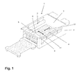
- FIG. 1 In the working area 3, a workpiece support 4 of conventional design is arranged, which serves for the storage of a sheet to be processed and also for the storage of the products of sheet metal processing. For the sake of simplicity, in FIG. 1 to be processed sheets and produced by the sheet metal processing products not shown.
- the laser cutting heads 5, 6 form functional units of the laser cutting machine and are moved by means of a moving unit 7 of the laser cutting machine 1.
- the movement unit 7 comprises a support structure in the form of a workpiece support 4 spanning machine portal 8 and a in FIG. 2 guide device 9 shown in detail, which guides the machine portal 8 in a feed direction 10 illustrated by a double arrow.
- the laser cutting heads 5, 6 by means not shown drive motors in a likewise symbolized by a double arrow guide transverse direction 11 movable.
- the machine portal 8 is moved jointly with the laser cutting heads 5, 6.
- a linear motor of conventional design is provided at each of the longitudinal ends of the machine gantry 8.
- the linear motors of the machine portal 8 are in the FIGS. 1 to 6 for the sake of simplicity not shown.
- the moving in the feed direction 10 part of each linear motor of the machine portal 8 is connected to a guide unit of the guide device 9.
- the guide units of the guide device 9 are formed as feed carriages 12, 13, which in FIG. 2 are shown very schematically.
- the feed slides 12, 13 are guided on stationary longitudinal guides 14, 15 of the guide device 9 in the feed direction 10 movable.
- the longitudinal guides 14, 15 are spaced apart in the guide transverse direction 11 and thereby form a gap in which the workpiece support 4 of the laser cutting machine 1 is arranged.
- the feed carriages 12, 13 are mounted without play on the longitudinal guides 14, 15 in the guide transverse direction 11.
- the feed carriages 12, 13 in turn support the machine gantry 8.
- a first bearing device 16 provided for supporting the machine gantry 8 on the feed carriage 12 permits exclusively a pivotal movement of the machine gantry 8 relative to the feed carriage 12.
- An axis 17, about which the machine portal 8 can pivot relative to the feed slide 12, runs perpendicular to the plane defined by the feed direction 10 and the guide transverse direction 11 horizontal plane.
- the pivoting mobility of the machine portal 8 about the axis 17 is in FIG. 2 indicated by a curved double arrow.
- the first bearing means 16 forms a fixed bearing, which accordingly supports the feed slide 12 and the machine gantry 8 in the feed direction 10 as well as in the guide transverse direction 11 without play.
- a second bearing device 18 at the opposite longitudinal end of the machine gantry 8 differs from the first bearing device 16 in that, in contrast to the first bearing device 16 in the guide transverse direction 11, it permits movements of the machine gantry 8 relative to the feed carriage 13.
- the second bearing device 18 thus forms a floating bearing for the machine gantry 8.
- the second bearing device 18 as well as the first bearing 16 acts as a fixed bearing in the feed direction 10.
- the second bearing means 18 permits Pivoting movements of the machine portal 8 relative to the associated guide unit of the guide device 9.
- An axis 19 about which the machine portal 8 can pivot relative to the feed carriage 13 is in FIG. 2 indicated. Also, the axis 19 is perpendicular to the plane defined by the feed direction 10 and the guide transverse direction 11 horizontal plane.
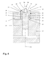
- the second bearing device 18 as bearing structure side bearing part provided on the machine portal 8 bearing receptacle in the form of a cam groove 20 with a receiving wall forming groove wall 21.
- a bearing projection in the form of a driver 22 is provided on the feed carriage 13.
- the driver 22 is fitted with a circular cylindrical bearing pin 23 without play in the feed carriage 13.
- the circular cylindrical bearing pin 23 is rotatably mounted on the feed carriage 13 with the formation of the axis 19.
- the portal-side part 24 of the driver 22 comprises a projection base 25 with wedge surfaces 26, 27 on opposite sides of the projection base 25 in the feed direction 10.
- the projection base 25 is associated with projection clamping elements in the form of clamping wedges 28, 29.
- the clamping wedge 28 lies with a wedge surface 30 on the wedge surface 26, the clamping wedge 29 with a wedge surface 31 on the wedge surface 27 of the projection base 25 at. Perpendicular to the feed direction 10, the clamping wedges 28, 29 acted upon by a pressure spring 32 acting as a biasing means.
- the pressure spring 32 is clamped between a resting on the clamping wedges 28, 29 pressure plate 33 and the underside of a screw head 34 a dowel screw 35. With its thread, the fitting screw 35 is screwed into an internal thread on the projection base 25.
- the clamping wedges 28, 29 and the two-sided wedge-shaped projection base 25 form a wedge gear. Under the action of the application of the pressure spring 32, the clamping wedges 28, 29 endeavor to move with their wedge surfaces 30, 31 along the wedge surfaces 26, 27 of the projection base 25. Due to the wedge effect, the clamping wedges 28, 29 are biased against the groove wall 21 of the cam groove 20. On its side facing the groove wall 21, the clamping wedges 28, 29 are provided with sliding linings 36, 37.
- the bias of the clamping wedges 28, 29 against the groove wall 21 is dimensioned such that in the feed direction 10 backlash-free support of the driver 22 on the groove wall 21 and thus in the feed direction 10 play-free storage of the machine portal 8 is secured to the feed carriage 13.
- the clamping wedges 28, 29 by the pressure spring 32 ensures that the bias of the clamping wedges 28, 29 against the groove wall 21 and consequently also the backlash-free support of the machine portal 8 on the feed slide 13 in the feed direction 10 in particular also when worn on the Clamping wedges 28, 29, approximately at the sliding linings 36, 37, maintained.
- the clamping wedges 28, 29 under the action of the pressure spring 32 with its wedge surfaces 30, 31 along the wedge surfaces 26, 27 of the projection base 25 is moved and added due to the wedge effect occurring in the feed direction 10 against the groove wall 21 of the slide groove 20.
- the size of the wedge angle on the clamping wedges 28, 29 and on the projection base 25 is selected such that the clamping wedges 28, 29 in case of need sufficiently far can be readjusted in the feed direction 10 and that at the same time adjusts the self-locking of the clamping wedges 28, 29 against movements relative to the projection base 25 at the contact surfaces located wedge surfaces 26, 30 and 27, 31, otherwise by in the feed direction 10 between the Machine portal 8 and the feed carriage 13 causes acting forces and would run against the action of the pressure spring 32.
- FIG. 5 are the clamping wedges 28, 29 differing from the conditions according to Figures 3 and 4 mechanically coupled with each other.
- the mechanical connection between the clamping wedges 28, 29 is made by means of a connecting bolt 38 which engages with its ends longitudinally movable in bores 39, 40 on the clamping wedges 28, 29 and on the projection base 25 in a slot 41 of the projection base 25 in the direction of Axis 19 is movably guided.
- the mechanical connection between the clamping wedges 28, 29, which is produced by means of the connecting bolt 38, ensures, in addition to the pressure wedges 28, 29, that the clamping wedges 28, 29 cover matching path lengths during adjustment movements in the direction of the axis 19.
- the centering of the driver 22 in the interior of the sliding groove 20 is thereby additionally secured.
- FIG. 6 shows the second bearing means 18 in an embodiment in which a projection base 45 of the driver 22 is provided only at one of its lying in the feed direction 10 sides with a wedge surface 46 and makes only a single clamping wedge 48 with a wedge surface 50 use.
- An adjusting movement is accordingly carried out only at one of the sides of the driver 22 located in the feed direction 10.
- At the clamping wedge 48 in the feed direction 10 opposite side of the driver 22 is supported without the interposition of a clamping element with the projection base 45 on the machine portal 8.
- the projection base 45 also has a sliding lining on the machine portal side.
Abstract
Description
Die Erfindung betrifft eine Bewegungseinheit einer Werkzeugmaschine
- mit einer in einer Vorschubrichtung bewegbaren Tragstruktur zur Lagerung einer Funktionseinheit der Werkzeugmaschine,
- mit einer Führungseinrichtung für die Tragstruktur, die zwei in der Vorschubrichtung verlaufende und quer dazu in einer Führungs-Querrichtung gegeneinander versetzt angeordnete Längsführungen aufweist, an denen jeweils eine Führungseinheit der Führungseinrichtung in der Vorschubrichtung bewegbar und in der Führungs-Querrichtung spielfrei gelagert ist sowie
- mit einer Lagereinrichtung, mittels derer die Tragstruktur an wenigstens einer der Führungseinheiten in der Vorschubrichtung spielfrei und in der Führungs-Querrichtung lose gelagert ist, indem die Lagereinrichtung einen der Tragstruktur zugeordneten tragstrukturseitigen Lagerteil sowie einen der Führungseinheit zugeordnetenen führungsseitigen Lagerteil umfasst, von denen der eine als sich in der Führungs-Querrichtung erstreckende Lageraufnahme mit einer Aufnahmewand und der andere als in die Lageraufnahme eingreifender Lagervorsprung ausgebildet ist, wobei der Lagervorsprung und die Aufnahmewand der Lageraufnahme in der Vorschubrichtung spielfrei aneinander gelagert sind und die Lageraufnahme in der Führungs-Querrichtung ein Übermaß gegenüber dem in die Lageraufnahme eingreifenden Lagervorsprung besitzt.
- with a support structure movable in a feed direction for supporting a functional unit of the machine tool,
- with a guide device for the support structure which has two longitudinal guides extending in the feed direction and offset transversely relative to one another in a guide transverse direction, on each of which a guide unit of the guide device is movable in the feed direction and is mounted free of play in the guide transverse direction and
- with a bearing device, by means of which the support structure is loosely mounted on at least one of the guide units in the feed direction and loosely in the guide transverse direction by the bearing means comprises a supporting structure associated support structure side bearing part and a guide unit associated guide side bearing part, one of which extending in the guide transverse direction bearing mount is formed with a receiving wall and the other as engaging in the bearing receptacle bearing projection, wherein the bearing projection and the receiving wall of the bearing support are stored in the feed direction without play together and the bearing receptacle in the Guide transverse direction has an oversize relative to the bearing receptacle engaging in the bearing projection.
Die Erfindung betrifft außerdem eine Werkzeugmaschine mit einer Bewegungseinheit der vorstehenden Art.The invention also relates to a machine tool having a moving unit of the above type.
Eine gattungsgemäße Bewegungseinheit sowie eine gattungsgemäße Werkzeugmaschine sind offenbart in
An dem Loslager einer Tragstruktur der vorstehenden Art eine dauerhaft spielfreie Lagerung der Tragstruktur in Vorschubrichtung sicherzustellen, ist Aufgabe der vorliegenden Erfindung.At the floating bearing of a support structure of the above type to ensure a permanently backlash-free storage of the support structure in the feed direction, is an object of the present invention.
Erfindungsgemäß gelöst wird diese Aufgabe durch die Bewegungseinheit gemäß Patentanspruch 1 sowie durch die Werkzeugmaschine gemäß Patentanspruch 10.This object is achieved according to the invention by the movement unit according to
Im Falle der Erfindung sind der Lagervorsprung und die Aufnahmewand der Lageraufnahme der in der Führungs-Querrichtung als Loslager wirkenden Lagerung in der Vorschubrichtung gegeneinander vorgespannt und unter der Wirkung dieser Vorspannung gegeneinander in der Vorschubrichtung nachsetzbar. Aufgrund der erfindungsgemäßen Merkmale stellt sich die in der Vorschubrichtung als Festlager wirkende Lagerung selbsttätig nach. Dadurch wird eine spielfreie gegenseitige Abstützung des Lagervorsprungs und der Aufnahmewand der Lageraufnahme in der Vorschubrichtung dauerhaft sichergestellt. Die spielfreie Lagerung in der Vorschubrichtung wird insbesondere auch durch Verschleiß an dem Lagervorsprung und/oder an der Aufnahmewand der Lageraufnahme nicht beeinträchtigt.In the case of the invention, the bearing projection and the receiving wall of the bearing receiver acting in the guide transverse direction as a floating bearing in the feed direction are biased against each other and under the effect of this bias against each other in the feed direction nachsetzbar. Due to the features of the invention acting in the feed direction as a fixed bearing storage automatically after. As a result, a play-free mutual support of the bearing projection and the receiving wall of the bearing support in the feed direction is permanently ensured. The play-free storage in the feed direction is not affected in particular by wear on the bearing projection and / or on the receiving wall of the bearing support.
Besondere Ausführungsarten der Bewegungseinheit nach Patentanspruch 1 und der Werkzeugmaschine nach Patentanspruch 10 ergeben sich aus den abhängigen Patentansprüchen 2 bis 9.Particular embodiments of the movement unit according to
Ausweislich Patentanspruch 2 ist in bevorzugter Ausgestaltung der Erfindung für den Lagervorsprung und/oder für die Aufnahmewand der Lageraufnahme eine mehrteilige Ausbildung vorgesehen. Die spielfreie gegenseitige Abstützung des Lagervorsprungs und der Aufnahmewand der Lageraufnahme wird mittels eines Spannelementes realisiert, das sich an einer zugehörigen Basis abstützt. Diese Mehrteiligkeit eröffnet auch die Möglichkeit, dasjenige Maschinenelement, das letztlich für die spielfreie gegenseitige Lagerung von Lagervorsprung und Aufnahmewand der Lageraufnahme sorgt, nämlich das Spannelement, an die Erfordernisse des jeweiligen Anwenclungsfalls anzupassen und bei Bedarf, etwa verschleißbedingt, gegen ein Ersatzteil auszutauschen.As shown in
Die Abstützung des Spannelementes an der zugeordneten Basis ist in weiterer Ausgestaltung der Erfindung nach Art eines Keilgetriebes ausgebildet (Patentanspruch 3). An dem Spannelement und/oder an der zugeordneten Basis ist eine in der Vorschubrichtung geneigte Keilfläche vorgesehen. Das Spannelement wird durch ein Vorspannmittel beaufschlagt. Über die Keilfläche(n) können ungeachtet einer platzsparenden Bauweise des Keilgetriebes große in Vorschubrichtung wirksame Belastungen abgetragen werden. Zum gegenseitigen Nachstellen des Lagervorsprungs und der Aufnahmewand der Lageraufnahme in der Vorschubrichtung bewegt sich das Spannelement unter der Wirkung des Vorspannmittels längs der oder den Keilflächen relativ zu der zugeordneten Basis senkrecht zu der Vorschubrichtung.The support of the clamping element on the associated base is formed in a further embodiment of the invention in the manner of a wedge gear (claim 3). On the tensioning element and / or on the associated base, a wedge surface inclined in the feed direction is provided. The clamping element is acted upon by a biasing means. Regardless of a space-saving design of the wedge gear, the wedge surface (s) can be effective in the feed direction Loads are removed. For mutual adjustment of the bearing projection and the receiving wall of the bearing receptacle in the feed direction, the clamping element moves under the action of the biasing means along the wedge or surfaces relative to the associated base perpendicular to the feed direction.
Eine Bewegung des Spannelementes in Gegenrichtung und somit eine unerwünschte Lockerung der spielfreien gegenseitigen Abstützung von Lagervorsprung und Aufnahmewand der Lageraufnahme in der Vorschubrichtung wird im Falle der Erfindungsbauart gemäß Patentanspruch 4 dadurch verhindert, dass das Spannelement an der zugehörigen Basis gegen eine entlang der Keilfläche(n) relativ zu der Basis ausgeführte Bewegung selbsthemmend abgestützt ist. Die selbsthemmende Abstützung kann durch entsprechende Wahl des Keilwinkels der Keilfläche an dem Spannelement und/oder der Keilfläche an der dem Spannelement zugeordneten Basis realisiert werden.A movement of the clamping element in the opposite direction and thus an undesirable loosening of the play-free mutual support of bearing projection and receiving wall of the bearing support in the feed direction is prevented in the case of Erfindungsbauart according to
Gemäß Patentanspruch 5 sind an dem Lagervorsprung und/oder an der Aufnahmewand der Lageraufnahme zwei an einer zugeordneten Basis abgestützte und in Vorschubrichtung gegenüber dem jeweils anderen Lagerteil nachsetzbare Spannelemente vorgesehen, die einander an der betreffenden Basis in der Vorschubrichtung gegenüberliegen. Das gegenseitige Nachstellen des Lagervorsprungs und der Aufnahmewand der Lageraufnahme wird demnach auf zwei Spannelemente aufgeteilt. Insbesondere ist folglich von einem der Spannelemente jeweils nur ein Teil des insgesamt erforderlichen Nachstellweges bereitzustellen.According to
Damit an beiden Spannelementen einheitliche Verhältnisse herrschen, ist in Weiterbildung der Erfindung vorgesehen, dass die Spannelemente, die an einander in der Vorschubrichtung gegenüberliegenden Seiten der zugeordneten Basis vorgesehen sind, mechanisch miteinander gekoppelt sind (Patentanspruch 6). Aufgrund der mechanischen Kopplung führen die Spannelemente Bewegungen zum Nachstellen der gegenseitigen Abstützung des Lagervorsprungs und der Aufnahmewand der Lageraufnahme gemeinschaftlich und mit einem übereinstimmenden Betrag aus.In order that uniform conditions prevail on the two clamping elements, it is provided in a development of the invention that the clamping elements, which are provided on opposite sides of the associated base in the feed direction, are mechanically coupled together (claim 6). Due to the mechanical coupling, the clamping elements perform movements for adjusting the mutual support of the bearing projection and the receiving wall of stocktaking collectively and with a matching amount.
Gemäß Patentanspruch 7 lässt die in der Vorschubrichtung spielfreie und in der Führungs-Querrichtung lose Lagerung der Tragstruktur an der Führungseinheit Schwenkbewegungen der Tragstruktur relativ zu der Führungseinheit um eine Achse zu, die senkrecht zu der von der Vorschubrichtung und der Führungs-Querrichtung aufgespannten Ebene verläuft. Derartige Schwenkbewegungen der Tragstruktur werden beispielsweise dann ausgeführt, wenn an den in der Führungs-Querrichtung gegeneinander versetzten Führungseinheiten unerwünschterweise auch ein Versatz in der Vorschubrichtung auftritt.According to
Ein derartiger gegenseitiger Versatz der in Führungs-Querrichtung voneinander beabstandeten Führungseinheiten kann sich insbesondere in dem für die betriebliche Praxis bedeutsamen Fall gemäß Patentanspruch 8 ergeben, in dem jede der beiden Führungseinheiten mittels eines eigenen Antriebsmotors in Vorschubrichtung bewegt wird und die Antriebsmotoren der Führungseinheiten nicht mechanisch miteinander verbunden sind.Such a mutual offset of the spaced apart in the guide transverse direction guide units may result in particular in the significant case for operational practice according to
Eine weitere in der Praxis häufig genutzte Ausführung der erfindungsgemäßen Bewegungseinheit ergibt sich aus Patentanspruch 9. Als Tragstruktur ist in diesem Fall ein Maschinenportal der Werkzeugmaschine vorgesehen.Another frequently used in practice embodiment of the movement unit according to the invention results from
Nachfolgend wird die Erfindung anhand beispielhafter schematischer Darstellungen näher erläutert. Es zeigen:
Figur 1- den grundsätzlichen Aufbau einer Laser-Schneidmaschine mit einer Bewegungseinheit,
Figur 2- die Bewegungseinheit der Laser-Schneidmaschine gemäß
Figur 1 Figur 3- das Detail III in
Figur 2 Figur 4- eine Schnittdarstellung der Anordnung gemäß
Figur 3Figur 3 Figuren 5 und 6- Alternativen zu der Anordnung gemäß den
Figuren 34 .
- FIG. 1
- the basic structure of a laser cutting machine with a moving unit,
- FIG. 2
- the moving unit of the laser cutting machine according to
FIG. 1 in the highly schematic plan view, - FIG. 3
- the detail III in
FIG. 2 in an enlarged view, - FIG. 4
- a sectional view of the arrangement according to
FIG. 3 in a sectional plane, the inFIG. 3 runs perpendicular to the plane along the line IV-IV and - FIGS. 5 and 6
- Alternatives to the arrangement according to the
Figures 3 and4 ,
Ausweislich
Zur schneidenden Bearbeitung wird ein auf der Werkstückauflage 4 gelagertes Blech von Laser-Schneidköpfen 5, 6 überfahren. Die Laser-Schneidköpfe 5, 6 bilden Funktionseinheiten der Laser-Schneidmaschine und werden mit Hilfe einer Bewegungseinheit 7 der Laser-Schneidmaschine 1 bewegt. Die Bewegungseinheit 7 umfasst eine Tragstruktur in Form eines die Werkstückauflage 4 überspannenden Maschinenportals 8 sowie eine in
An dem Maschinenportal 8 sind die Laser-Schneidköpfe 5, 6 mittels nicht dargestellter Antriebsmotoren in einer gleichfalls durch einen Doppelpfeil symbolisierten Führungs-Querrichtung 11 verfahrbar. In der Vorschubrichtung 10 wird das Maschinenportal 8 gemeinschaftlich mit den Laser-Schneidköpfen 5, 6 bewegt. Zu diesem Zweck ist an jedem der Längsenden des Maschinenportals 8 ein Linearmotor herkömmlicher Bauart vorgesehen. Auch die Linearmotoren des Maschinenportals 8 sind in den
Die Vorschubschlitten 12, 13 ihrerseits lagern das Maschinenportal 8. Dabei lässt eine zur Lagerung des Maschinenportals 8 an dem Vorschubschlitten 12 vorgesehene erste Lagereinrichtung 16 ausschließlich eine Schwenkbewegung des Maschinenportals 8 relativ zu dem Vorschubschlitten 12 zu. Eine Achse 17, um welche das Maschinenportal 8 relativ zu dem Vorschubschlitten 12 schwenken kann, verläuft senkrecht zu der von der Vorschubrichtung 10 und der Führungs-Querrichtung 11 aufgespannten Horizontalebene. Die Schwenkbeweglichkeit des Maschinenportals 8 um die Achse 17 ist in
Eine zweite Lagereinrichtung 18 an dem gegenüberliegenden Längsende des Maschinenportals 8 unterscheidet sich von der ersten Lagereinrichtung 16 insofern, als sie im Gegensatz zu der ersten Lagereinrichtung 16 in der Führungs-Querrichtung 11 Bewegungen des Maschinenportals 8 relativ zu dem Vorschubschlitten 13 erlaubt. In der Führungs-Querrichtung 11 bildet die zweite Lagereinrichtung 18 folglich ein Loslager für das Maschinenportal 8. Im Übrigen wirkt die zweite Lagereinrichtung 18 ebenso wie die erste Lagereinrichtung 16 als Festlager in der Vorschubrichtung 10. Und auch die zweite Lagereinrichtung 18 gestattet Schwenkbewegungen des Maschinenportals 8 relativ zu der zugeordneten Führungseinheit der Führungseinrichtung 9. Eine Achse 19, um welche das Maschinenportal 8 relativ zu dem Vorschubschlitten 13 schwenken kann, ist in
Wie an der zweiten Lagereinrichtung 18 die Festlagerfunktion in der Vorschubrichtung 10 und die Loslagerfunktion in der Führungs-Querrichtung 11 konstruktiv miteinander kombiniert sind, ergibt sich aus den
Gemäß den
Mit einem portalseitigen Teil 24 greift der mit dem Vorschubschlitten 13 verbundene Mitnehmer 22 in die Kulissennut 20 an dem Maschinenportal 8 ein. Im Einzelnen umfasst der portalseitige Teil 24 des Mitnehmers 22 eine Vorsprungbasis 25 mit Keilflächen 26, 27 an einander in der Vorschubrichtung 10 gegenüberliegenden Seiten der Vorsprungbasis 25. Der Vorsprungbasis 25 zugeordnet sind Vorsprung-Spannelemente in Form von Spannkeilen 28, 29. Der Spannkeil 28 liegt mit einer Keilfläche 30 an der Keilfläche 26, der Spannkeil 29 mit einer Keilfläche 31 an der Keilfläche 27 der Vorsprungbasis 25 an. Senkrecht zu der Vorschubrichtung 10 werden die Spannkeile 28, 29 durch eine als Vorspannmittel dienende Andruckfeder 32 beaufschlagt. Die Andruckfeder 32 ist zwischen einer auf den Spannkeilen 28, 29 aufliegenden Druckplatte 33 und der Unterseite eines Schraubenkopfes 34 einer Passschraube 35 verspannt. Mit ihrem Gewinde ist die Passschraube 35 in ein Innengewinde an der Vorsprungbasis 25 eingeschraubt. Die Spannkeile 28, 29 und die zweiseitig keilförmige Vorsprungbasis 25 bilden ein Keilgetriebe. Unter der Wirkung der Beaufschlagung durch die Andruckfeder 32 sind die Spannkeile 28, 29 bestrebt, sich mit ihren Keilflächen 30, 31 längs der Keilflächen 26, 27 der Vorsprungbasis 25 zu verlagern. Durch die Keilwirkung werden die Spannkeile 28, 29 gegen die Nutwand 21 der Kulissennut 20 vorgespannt. An ihrer der Nutwand 21 zugewandten Seite sind die Spannkeile 28, 29 mit Gleitbelägen 36, 37 versehen.With a portal-
Die Vorspannung der Spannkeile 28, 29 gegen die Nutwand 21 ist derart bemessen, dass in der Vorschubrichtung 10 eine spielfreie Abstützung des Mitnehmers 22 an der Nutwand 21 und somit eine in der Vorschubrichtung 10 spielfreie Lagerung des Maschinenportals 8 an dem Vorschubschlitten 13 sichergestellt ist. Gleichzeitig lässt die Vorspannung der Spannkeile 28, 29 gegen die Nutwand 21 in der Führungs-Querrichtung 11 Bewegungen der Nutwand 21 gegenüber den Spannkeilen 28, 29 und somit Bewegungen des Maschinenportals 8 relativ zu dem Vorschubschlitten 13 zu. Erleichtert werden in der Führungs-Querrichtung 11 ausgeführte Bewegungen des Maschinenportals 8 relativ zu dem Vorschubschlitten 13 durch die Gleitbeläge 36, 37 der Spannkeile 28, 29.The bias of the clamping
Aufgrund der Beaufschlagung der Spannkeile 28, 29 durch die Andruckfeder 32 ist gewährleistet, dass die Vorspannung der Spannkeile 28, 29 gegen die Nutwand 21 und folglich auch die spielfreie Abstützung des Maschinenportals 8 an dem Vorschubschlitten 13 in der Vorschubrichtung 10 insbesondere auch bei Verschleiß an den Spannkeilen 28, 29, etwa an den Gleitbelägen 36, 37, aufrechterhalten bleibt. In derartigen Fällen werden die Spannkeile 28, 29 unter der Wirkung der Andruckfeder 32 mit ihren Keilflächen 30, 31 längs der Keilflächen 26, 27 der Vorsprungbasis 25 bewegt und aufgrund der dabei auftretenden Keilwirkung in der Vorschubrichtung 10 gegen die Nutwand 21 der Kulissennut 20 nachgesetzt.Due to the action of the clamping
Die Größe der Keilwinkel an den Spannkeilen 28, 29 und an der Vorsprungbasis 25 ist derart gewählt, dass die Spannkeile 28, 29 im Bedarfsfall hinreichend weit in der Vorschubrichtung 10 nachgestellt werden können und dass sich gleichzeitig an den miteinander in Kontakt befindlichen Keilflächen 26, 30 und 27, 31 eine Selbsthemmung der Spannkeile 28, 29 gegen Bewegungen relativ zu der Vorsprungbasis 25 einstellt, die ansonsten durch in der Vorschubrichtung 10 zwischen dem Maschinenportal 8 und dem Vorschubschlitten 13 wirkende Kräfte verursacht und die gegen die Wirkung der Andruckfeder 32 ausgeführt würden.The size of the wedge angle on the clamping
Anstelle der in den
In
Claims (10)
der Lagervorsprung (22) und die Aufnahmewand (21) der Lageraufnahme (20) in der Vorschubrichtung (10) spielfrei aneinander gelagert sind, indem der Lagervorsprung (22) und die Aufnahmewand (21) der Lageraufnahme (20) in der Vorschubrichtung (10) gegeneinander vorgespannt und unter der Wirkung der Vorspannung in der Vorschubrichtung (10) gegeneinander nachsetzbar sind.
the bearing projection (22) and the receiving wall (21) of the bearing receiver (20) are mounted without play in the feed direction (10) by the bearing projection (22) and the receiving wall (21) of the bearing receiver (20) in the feed direction (10) biased against each other and under the action of the bias in the feed direction (10) against each other are nachsetzbar.
Priority Applications (2)
| Application Number | Priority Date | Filing Date | Title |
|---|---|---|---|
| EP12169323.8A EP2666583B1 (en) | 2012-05-24 | 2012-05-24 | Motion unit of a machine tool and machine tool with such a motion unit |
| US13/901,701 US8944685B2 (en) | 2012-05-24 | 2013-05-24 | Movement unit for a machine tool and machine tool with such a movement unit |
Applications Claiming Priority (1)
| Application Number | Priority Date | Filing Date | Title |
|---|---|---|---|
| EP12169323.8A EP2666583B1 (en) | 2012-05-24 | 2012-05-24 | Motion unit of a machine tool and machine tool with such a motion unit |
Publications (2)
| Publication Number | Publication Date |
|---|---|
| EP2666583A1 true EP2666583A1 (en) | 2013-11-27 |
| EP2666583B1 EP2666583B1 (en) | 2015-01-21 |
Family
ID=46168260
Family Applications (1)
| Application Number | Title | Priority Date | Filing Date |
|---|---|---|---|
| EP12169323.8A Active EP2666583B1 (en) | 2012-05-24 | 2012-05-24 | Motion unit of a machine tool and machine tool with such a motion unit |
Country Status (2)
| Country | Link |
|---|---|
| US (1) | US8944685B2 (en) |
| EP (1) | EP2666583B1 (en) |
Cited By (3)
| Publication number | Priority date | Publication date | Assignee | Title |
|---|---|---|---|---|
| EP3112083A1 (en) | 2015-07-03 | 2017-01-04 | TRUMPF Werkzeugmaschinen GmbH + Co. KG | Portal assembly of a machine tool and machine tool with such a portal assembly |
| WO2017199268A1 (en) * | 2016-05-19 | 2017-11-23 | IMI STI S.r.l. | Device for a valve shutter displacement |
| DE202020103429U1 (en) | 2020-06-16 | 2020-06-23 | Trumpf Werkzeugmaschinen Gmbh + Co. Kg | Movement unit of a machine tool for machining workpieces and machine tool with such a movement unit |
Families Citing this family (1)
| Publication number | Priority date | Publication date | Assignee | Title |
|---|---|---|---|---|
| DE202015105035U1 (en) | 2015-09-23 | 2015-10-12 | Igus Gmbh | Linear guide with self-adjusting clearance reduction |
Citations (5)
| Publication number | Priority date | Publication date | Assignee | Title |
|---|---|---|---|---|
| US3790233A (en) * | 1971-11-10 | 1974-02-05 | Automation Gages Inc | Antifriction slide assembly |
| GB2218121A (en) * | 1988-04-30 | 1989-11-08 | Voith Gmbh J M | Roll displacing equipment |
| EP0935511A1 (en) | 1997-08-28 | 1999-08-18 | SÄCHSISCHE WERKZEUG UND SONDERMASCHINEN GmbH | Support for a machine tool portal driven by linear motors on both sides |
| US6372179B1 (en) * | 1999-07-27 | 2002-04-16 | Promotec S.R.L. | Metal plate cutting machine |
| US20090110336A1 (en) * | 2006-05-16 | 2009-04-30 | Niedermeyer John F | Adjustable Linear Slide and Method of Assembly |
Family Cites Families (3)
| Publication number | Priority date | Publication date | Assignee | Title |
|---|---|---|---|---|
| DE20013363U1 (en) * | 2000-08-03 | 2000-12-21 | Igus Gmbh | Floating bearing |
| JP3810269B2 (en) * | 2000-11-22 | 2006-08-16 | アイダエンジニアリング株式会社 | Slide guide device for press machine |
| US6842961B2 (en) * | 2001-05-31 | 2005-01-18 | Murray Forlong | Methods and apparatus for a linear guiding device |
-
2012
- 2012-05-24 EP EP12169323.8A patent/EP2666583B1/en active Active
-
2013
- 2013-05-24 US US13/901,701 patent/US8944685B2/en active Active
Patent Citations (5)
| Publication number | Priority date | Publication date | Assignee | Title |
|---|---|---|---|---|
| US3790233A (en) * | 1971-11-10 | 1974-02-05 | Automation Gages Inc | Antifriction slide assembly |
| GB2218121A (en) * | 1988-04-30 | 1989-11-08 | Voith Gmbh J M | Roll displacing equipment |
| EP0935511A1 (en) | 1997-08-28 | 1999-08-18 | SÄCHSISCHE WERKZEUG UND SONDERMASCHINEN GmbH | Support for a machine tool portal driven by linear motors on both sides |
| US6372179B1 (en) * | 1999-07-27 | 2002-04-16 | Promotec S.R.L. | Metal plate cutting machine |
| US20090110336A1 (en) * | 2006-05-16 | 2009-04-30 | Niedermeyer John F | Adjustable Linear Slide and Method of Assembly |
Cited By (4)
| Publication number | Priority date | Publication date | Assignee | Title |
|---|---|---|---|---|
| EP3112083A1 (en) | 2015-07-03 | 2017-01-04 | TRUMPF Werkzeugmaschinen GmbH + Co. KG | Portal assembly of a machine tool and machine tool with such a portal assembly |
| WO2017199268A1 (en) * | 2016-05-19 | 2017-11-23 | IMI STI S.r.l. | Device for a valve shutter displacement |
| CN109312833A (en) * | 2016-05-19 | 2019-02-05 | 伊米斯蒂有限责任公司 | Device for the displacement of valve valve |
| DE202020103429U1 (en) | 2020-06-16 | 2020-06-23 | Trumpf Werkzeugmaschinen Gmbh + Co. Kg | Movement unit of a machine tool for machining workpieces and machine tool with such a movement unit |
Also Published As
| Publication number | Publication date |
|---|---|
| EP2666583B1 (en) | 2015-01-21 |
| US20140332654A1 (en) | 2014-11-13 |
| US8944685B2 (en) | 2015-02-03 |
Similar Documents
| Publication | Publication Date | Title |
|---|---|---|
| EP2197660B1 (en) | movable slide element for a wedge drive and wedge drive with such movable slide element | |
| EP2392438B1 (en) | Processing device | |
| EP2666583B1 (en) | Motion unit of a machine tool and machine tool with such a motion unit | |
| EP3563959A1 (en) | Sawing device | |
| EP1990160A2 (en) | Through feed drilling machine | |
| EP3238848B1 (en) | Method for compensating for a production-induced offset in a tool slide | |
| EP2314393B1 (en) | Press with tool changing device | |
| EP1878534B1 (en) | Device for tilting a working spindle comprising a hinge | |
| DE102008051378B4 (en) | Bending tool, apparatus and method for bending electrical pin contacts | |
| EP2046545B1 (en) | Apparatus for producing and/or processing panels | |
| WO2013166539A1 (en) | Transfer centre for machining at least one workpiece, with a position compensation system | |
| DE102013206159B4 (en) | Panel sizing machine | |
| EP2885108B1 (en) | Lifting apparatus having a toggle lever mechanism | |
| EP3254804A2 (en) | Device and method for the trimming of glass tables | |
| DE4440754C1 (en) | Cutter for sheet materials in stacks e.g. paper or cardboard | |
| EP2845663B1 (en) | Bending press with a bending tool comprising a plurality of tool parts | |
| DE2951355A1 (en) | ROLLING TABLE FOR WOODWORKING MACHINES | |
| EP2928680B1 (en) | Press brake | |
| WO2019052856A1 (en) | Steady rest for supporting a workpiece being machined | |
| EP1837145B1 (en) | Machining apparatus for plate-like workpieces | |
| AT516718B1 (en) | bending machine | |
| DE3331905C2 (en) | Laser beam processing machine | |
| DE102020124126B3 (en) | Sheet metal bending machine with stop system | |
| DE10345846B4 (en) | Long scooter for rolling long pieces of dough | |
| EP0764508A2 (en) | Tie bar-less mould clamping device for an injection moulding machine |
Legal Events
| Date | Code | Title | Description |
|---|---|---|---|
| PUAI | Public reference made under article 153(3) epc to a published international application that has entered the european phase |
Free format text: ORIGINAL CODE: 0009012 |
|
| AK | Designated contracting states |
Kind code of ref document: A1 Designated state(s): AL AT BE BG CH CY CZ DE DK EE ES FI FR GB GR HR HU IE IS IT LI LT LU LV MC MK MT NL NO PL PT RO RS SE SI SK SM TR |
|
| AX | Request for extension of the european patent |
Extension state: BA ME |
|
| 17P | Request for examination filed |
Effective date: 20140527 |
|
| RBV | Designated contracting states (corrected) |
Designated state(s): AL AT BE BG CH CY CZ DE DK EE ES FI FR GB GR HR HU IE IS IT LI LT LU LV MC MK MT NL NO PL PT RO RS SE SI SK SM TR |
|
| RIC1 | Information provided on ipc code assigned before grant |
Ipc: F16C 29/12 20060101ALI20140627BHEP Ipc: B23Q 1/01 20060101AFI20140627BHEP |
|
| GRAP | Despatch of communication of intention to grant a patent |
Free format text: ORIGINAL CODE: EPIDOSNIGR1 |
|
| INTG | Intention to grant announced |
Effective date: 20140825 |
|
| GRAS | Grant fee paid |
Free format text: ORIGINAL CODE: EPIDOSNIGR3 |
|
| GRAA | (expected) grant |
Free format text: ORIGINAL CODE: 0009210 |
|
| AK | Designated contracting states |
Kind code of ref document: B1 Designated state(s): AL AT BE BG CH CY CZ DE DK EE ES FI FR GB GR HR HU IE IS IT LI LT LU LV MC MK MT NL NO PL PT RO RS SE SI SK SM TR |
|
| REG | Reference to a national code |
Ref country code: GB Ref legal event code: FG4D Free format text: NOT ENGLISH |
|
| REG | Reference to a national code |
Ref country code: CH Ref legal event code: EP |
|
| REG | Reference to a national code |
Ref country code: IE Ref legal event code: FG4D Free format text: LANGUAGE OF EP DOCUMENT: GERMAN |
|
| REG | Reference to a national code |
Ref country code: DE Ref legal event code: R096 Ref document number: 502012002152 Country of ref document: DE Effective date: 20150305 |
|
| REG | Reference to a national code |
Ref country code: AT Ref legal event code: REF Ref document number: 708927 Country of ref document: AT Kind code of ref document: T Effective date: 20150315 |
|
| REG | Reference to a national code |
Ref country code: NL Ref legal event code: VDEP Effective date: 20150121 |
|
| REG | Reference to a national code |
Ref country code: LT Ref legal event code: MG4D |
|
| PG25 | Lapsed in a contracting state [announced via postgrant information from national office to epo] |
Ref country code: BG Free format text: LAPSE BECAUSE OF FAILURE TO SUBMIT A TRANSLATION OF THE DESCRIPTION OR TO PAY THE FEE WITHIN THE PRESCRIBED TIME-LIMIT Effective date: 20150421 Ref country code: LT Free format text: LAPSE BECAUSE OF FAILURE TO SUBMIT A TRANSLATION OF THE DESCRIPTION OR TO PAY THE FEE WITHIN THE PRESCRIBED TIME-LIMIT Effective date: 20150121 Ref country code: ES Free format text: LAPSE BECAUSE OF FAILURE TO SUBMIT A TRANSLATION OF THE DESCRIPTION OR TO PAY THE FEE WITHIN THE PRESCRIBED TIME-LIMIT Effective date: 20150121 Ref country code: NO Free format text: LAPSE BECAUSE OF FAILURE TO SUBMIT A TRANSLATION OF THE DESCRIPTION OR TO PAY THE FEE WITHIN THE PRESCRIBED TIME-LIMIT Effective date: 20150421 Ref country code: SE Free format text: LAPSE BECAUSE OF FAILURE TO SUBMIT A TRANSLATION OF THE DESCRIPTION OR TO PAY THE FEE WITHIN THE PRESCRIBED TIME-LIMIT Effective date: 20150121 Ref country code: HR Free format text: LAPSE BECAUSE OF FAILURE TO SUBMIT A TRANSLATION OF THE DESCRIPTION OR TO PAY THE FEE WITHIN THE PRESCRIBED TIME-LIMIT Effective date: 20150121 |
|
| PG25 | Lapsed in a contracting state [announced via postgrant information from national office to epo] |
Ref country code: LV Free format text: LAPSE BECAUSE OF FAILURE TO SUBMIT A TRANSLATION OF THE DESCRIPTION OR TO PAY THE FEE WITHIN THE PRESCRIBED TIME-LIMIT Effective date: 20150121 Ref country code: NL Free format text: LAPSE BECAUSE OF FAILURE TO SUBMIT A TRANSLATION OF THE DESCRIPTION OR TO PAY THE FEE WITHIN THE PRESCRIBED TIME-LIMIT Effective date: 20150121 Ref country code: RS Free format text: LAPSE BECAUSE OF FAILURE TO SUBMIT A TRANSLATION OF THE DESCRIPTION OR TO PAY THE FEE WITHIN THE PRESCRIBED TIME-LIMIT Effective date: 20150121 Ref country code: IS Free format text: LAPSE BECAUSE OF FAILURE TO SUBMIT A TRANSLATION OF THE DESCRIPTION OR TO PAY THE FEE WITHIN THE PRESCRIBED TIME-LIMIT Effective date: 20150521 Ref country code: PL Free format text: LAPSE BECAUSE OF FAILURE TO SUBMIT A TRANSLATION OF THE DESCRIPTION OR TO PAY THE FEE WITHIN THE PRESCRIBED TIME-LIMIT Effective date: 20150121 Ref country code: GR Free format text: LAPSE BECAUSE OF FAILURE TO SUBMIT A TRANSLATION OF THE DESCRIPTION OR TO PAY THE FEE WITHIN THE PRESCRIBED TIME-LIMIT Effective date: 20150422 |
|
| REG | Reference to a national code |
Ref country code: DE Ref legal event code: R097 Ref document number: 502012002152 Country of ref document: DE |
|
| PG25 | Lapsed in a contracting state [announced via postgrant information from national office to epo] |
Ref country code: RO Free format text: LAPSE BECAUSE OF FAILURE TO SUBMIT A TRANSLATION OF THE DESCRIPTION OR TO PAY THE FEE WITHIN THE PRESCRIBED TIME-LIMIT Effective date: 20150121 Ref country code: SK Free format text: LAPSE BECAUSE OF FAILURE TO SUBMIT A TRANSLATION OF THE DESCRIPTION OR TO PAY THE FEE WITHIN THE PRESCRIBED TIME-LIMIT Effective date: 20150121 Ref country code: EE Free format text: LAPSE BECAUSE OF FAILURE TO SUBMIT A TRANSLATION OF THE DESCRIPTION OR TO PAY THE FEE WITHIN THE PRESCRIBED TIME-LIMIT Effective date: 20150121 Ref country code: DK Free format text: LAPSE BECAUSE OF FAILURE TO SUBMIT A TRANSLATION OF THE DESCRIPTION OR TO PAY THE FEE WITHIN THE PRESCRIBED TIME-LIMIT Effective date: 20150121 Ref country code: CZ Free format text: LAPSE BECAUSE OF FAILURE TO SUBMIT A TRANSLATION OF THE DESCRIPTION OR TO PAY THE FEE WITHIN THE PRESCRIBED TIME-LIMIT Effective date: 20150121 |
|
| PLBE | No opposition filed within time limit |
Free format text: ORIGINAL CODE: 0009261 |
|
| STAA | Information on the status of an ep patent application or granted ep patent |
Free format text: STATUS: NO OPPOSITION FILED WITHIN TIME LIMIT |
|
| 26N | No opposition filed |
Effective date: 20151022 |
|
| PG25 | Lapsed in a contracting state [announced via postgrant information from national office to epo] |
Ref country code: MC Free format text: LAPSE BECAUSE OF FAILURE TO SUBMIT A TRANSLATION OF THE DESCRIPTION OR TO PAY THE FEE WITHIN THE PRESCRIBED TIME-LIMIT Effective date: 20150121 Ref country code: LU Free format text: LAPSE BECAUSE OF FAILURE TO SUBMIT A TRANSLATION OF THE DESCRIPTION OR TO PAY THE FEE WITHIN THE PRESCRIBED TIME-LIMIT Effective date: 20150524 |
|
| REG | Reference to a national code |
Ref country code: IE Ref legal event code: MM4A |
|
| REG | Reference to a national code |
Ref country code: FR Ref legal event code: ST Effective date: 20160129 |
|
| PG25 | Lapsed in a contracting state [announced via postgrant information from national office to epo] |
Ref country code: SI Free format text: LAPSE BECAUSE OF FAILURE TO SUBMIT A TRANSLATION OF THE DESCRIPTION OR TO PAY THE FEE WITHIN THE PRESCRIBED TIME-LIMIT Effective date: 20150121 |
|
| PG25 | Lapsed in a contracting state [announced via postgrant information from national office to epo] |
Ref country code: IE Free format text: LAPSE BECAUSE OF NON-PAYMENT OF DUE FEES Effective date: 20150524 |
|
| PG25 | Lapsed in a contracting state [announced via postgrant information from national office to epo] |
Ref country code: FR Free format text: LAPSE BECAUSE OF NON-PAYMENT OF DUE FEES Effective date: 20150601 |
|
| PG25 | Lapsed in a contracting state [announced via postgrant information from national office to epo] |
Ref country code: MT Free format text: LAPSE BECAUSE OF FAILURE TO SUBMIT A TRANSLATION OF THE DESCRIPTION OR TO PAY THE FEE WITHIN THE PRESCRIBED TIME-LIMIT Effective date: 20150121 |
|
| GBPC | Gb: european patent ceased through non-payment of renewal fee |
Effective date: 20160524 |
|
| PG25 | Lapsed in a contracting state [announced via postgrant information from national office to epo] |
Ref country code: SM Free format text: LAPSE BECAUSE OF FAILURE TO SUBMIT A TRANSLATION OF THE DESCRIPTION OR TO PAY THE FEE WITHIN THE PRESCRIBED TIME-LIMIT Effective date: 20150121 Ref country code: GB Free format text: LAPSE BECAUSE OF NON-PAYMENT OF DUE FEES Effective date: 20160524 Ref country code: HU Free format text: LAPSE BECAUSE OF FAILURE TO SUBMIT A TRANSLATION OF THE DESCRIPTION OR TO PAY THE FEE WITHIN THE PRESCRIBED TIME-LIMIT; INVALID AB INITIO Effective date: 20120524 |
|
| PG25 | Lapsed in a contracting state [announced via postgrant information from national office to epo] |
Ref country code: CY Free format text: LAPSE BECAUSE OF FAILURE TO SUBMIT A TRANSLATION OF THE DESCRIPTION OR TO PAY THE FEE WITHIN THE PRESCRIBED TIME-LIMIT Effective date: 20150121 |
|
| PG25 | Lapsed in a contracting state [announced via postgrant information from national office to epo] |
Ref country code: BE Free format text: LAPSE BECAUSE OF NON-PAYMENT OF DUE FEES Effective date: 20150531 |
|
| PG25 | Lapsed in a contracting state [announced via postgrant information from national office to epo] |
Ref country code: TR Free format text: LAPSE BECAUSE OF FAILURE TO SUBMIT A TRANSLATION OF THE DESCRIPTION OR TO PAY THE FEE WITHIN THE PRESCRIBED TIME-LIMIT Effective date: 20150121 |
|
| PG25 | Lapsed in a contracting state [announced via postgrant information from national office to epo] |
Ref country code: MK Free format text: LAPSE BECAUSE OF FAILURE TO SUBMIT A TRANSLATION OF THE DESCRIPTION OR TO PAY THE FEE WITHIN THE PRESCRIBED TIME-LIMIT Effective date: 20150121 Ref country code: PT Free format text: LAPSE BECAUSE OF FAILURE TO SUBMIT A TRANSLATION OF THE DESCRIPTION OR TO PAY THE FEE WITHIN THE PRESCRIBED TIME-LIMIT Effective date: 20150121 |
|
| PG25 | Lapsed in a contracting state [announced via postgrant information from national office to epo] |
Ref country code: AL Free format text: LAPSE BECAUSE OF FAILURE TO SUBMIT A TRANSLATION OF THE DESCRIPTION OR TO PAY THE FEE WITHIN THE PRESCRIBED TIME-LIMIT Effective date: 20150121 |
|
| PGFP | Annual fee paid to national office [announced via postgrant information from national office to epo] |
Ref country code: IT Payment date: 20230526 Year of fee payment: 12 Ref country code: DE Payment date: 20230519 Year of fee payment: 12 Ref country code: CH Payment date: 20230605 Year of fee payment: 12 |
|
| PGFP | Annual fee paid to national office [announced via postgrant information from national office to epo] |
Ref country code: FI Payment date: 20230523 Year of fee payment: 12 Ref country code: AT Payment date: 20230522 Year of fee payment: 12 |