EP2666397A1 - Kitchen appliance with a mixing bowl and method for installing the same - Google Patents
Kitchen appliance with a mixing bowl and method for installing the same Download PDFInfo
- Publication number
- EP2666397A1 EP2666397A1 EP13167279.2A EP13167279A EP2666397A1 EP 2666397 A1 EP2666397 A1 EP 2666397A1 EP 13167279 A EP13167279 A EP 13167279A EP 2666397 A1 EP2666397 A1 EP 2666397A1
- Authority
- EP
- European Patent Office
- Prior art keywords
- receiving part
- food processor
- housing
- weighing modules
- chassis
- Prior art date
- Legal status (The legal status is an assumption and is not a legal conclusion. Google has not performed a legal analysis and makes no representation as to the accuracy of the status listed.)
- Granted
Links
Images


Classifications
-
- A—HUMAN NECESSITIES
- A47—FURNITURE; DOMESTIC ARTICLES OR APPLIANCES; COFFEE MILLS; SPICE MILLS; SUCTION CLEANERS IN GENERAL
- A47J—KITCHEN EQUIPMENT; COFFEE MILLS; SPICE MILLS; APPARATUS FOR MAKING BEVERAGES
- A47J43/00—Implements for preparing or holding food, not provided for in other groups of this subclass
- A47J43/04—Machines for domestic use not covered elsewhere, e.g. for grinding, mixing, stirring, kneading, emulsifying, whipping or beating foodstuffs, e.g. power-driven
- A47J43/07—Parts or details, e.g. mixing tools, whipping tools
- A47J43/0716—Parts or details, e.g. mixing tools, whipping tools for machines with tools driven from the lower side
-
- A—HUMAN NECESSITIES
- A47—FURNITURE; DOMESTIC ARTICLES OR APPLIANCES; COFFEE MILLS; SPICE MILLS; SUCTION CLEANERS IN GENERAL
- A47J—KITCHEN EQUIPMENT; COFFEE MILLS; SPICE MILLS; APPARATUS FOR MAKING BEVERAGES
- A47J27/00—Cooking-vessels
- A47J27/004—Cooking-vessels with integral electrical heating means
Definitions
- the invention relates firstly to a food processor with a mixing vessel and a stirrer in the mixing vessel, further comprising an electrically driven motor for driving the agitator, with a chassis formed as a supporting housing part and a bottom forming the housing pan, wherein further device feet are provided with Weighing modules are connected.
- Food processors of the type in question are known. It is for example on the DE 10219 442 A1 directed. Such kitchen machines are used, in particular in the household sector, for the processing of foods, and more preferably for the preparation of meals in the mixing vessel.
- the mixing vessel is preferably liftable from a machine-side vessel receptacle.
- An agitator which is preferably provided in the mixing vessel, more preferably on the bottom side, is driven in the arrangement of the mixing vessel in the vessel receptacle via an electric motor arranged in the food processor.
- the machine chassis is designed to receive the over the machine itself, further on the mixing vessel and the contents in the mixing vessel acting weights, further the housing part directly supporting, the chassis training is designed, or at least with the housing enclosed by the chassis connected is.
- a housing pan shapes the bottom of the food processor. Further bottom side feet are provided for parking the kitchen machine, for example, on a work surface. These preferably carry the entire weight of the food processor, more preferably in the operation of the same including the removable parts such as mixing vessel, lid for the mixing vessel, etc., beyond the contents of the mixing vessel.
- the determined and displayed weight is preferably the weight of the mixing vessel contents, so that the other weights, in particular that of the food processor itself, are excluded from the evaluation.
- a possible solution to the problem is given according to a first inventive concept in a food processor, which is geared to the fact that the weighing modules are connected to a common receiving part, which has the necessary wiring for the weighing modules, the device tub even with mounted feet with the chassis connectable and / or detachable from the chassis.
- a food processor of the type in question is given, which proves to be favorable in particular with regard to the assembly or disassembly.
- the weighing modules are preferably prefabricated arranged on a common receiving part, which receiving part is quasi a collection module.
- the necessary wiring for the weighing modules in the receiving part arranged in advance, so that in a preferred embodiment for mounting the food processor with respect to the weighing modules alone the insertion of the receiving part is required, which hereafter also the weigh modules are arranged in their predetermined position with respect to the food processor ,
- a complex arrangement of individual weighing modules in the course of device assembly and accordingly also the complex wiring of the weighing modules is preferably eliminated in the course of machine assembly.
- the device feet are already arranged on the weigh modules connected to the receiving part.
- the arrangement is further selected such that the device feet mounted on the receiving part, more preferably on the weighing modules, enforce the appliance pan for supporting the food processor on a work surface or the like.
- the device tub can also be connected to the chassis of the food processor, in particular by means of the device pan, by means of device bases, in particular by lifting the device tub and fixing it to the chassis, for example by screwing or gluing.
- a release of the device tub from the chassis through the device trough sweeping device feet allows this further, in particular after removal of a connection between the device tub and chassis according to lowering the device tub in a preferred storage position, in which the device tub more preferably on the same surface rests on which also support the device feet.
- the device tray in a preferred embodiment of the device feet interspersed openings. These openings are further preferred in terms of their floor plan opening areas adapted to the largest footprint of the device feet, so that the latter can completely enforce the device tub or the bottom portion of the device tub.
- the proposed solution allows a mounting of the food processor alone from above by preferably on the appliance pan all components, preferably starting with the weighing modules and preferably the device feet having receiving part are placed in more preferably final lifting the device tub and fixing the same on the Chassis.
- a disassembly is preferably in reverse order, wherein Alone by lowering the device tub in a further preferred embodiment already allows access to the wiring of the weighing modules.
- a food processor which is geared to that the weighing modules are connected to a common receiving part and that the receiving part is also designed to hold the engine and / or forms an air duct for engine cooling ,
- the receiving part is designed in the manner of a collecting module, which already carries the weigh modules in the course of machine assembly and preferably also forms the holder of the electric motor for the agitator. Accordingly, this achieves a reduction of the assembly steps in the course of food processor assembly, this further preferably also additionally or alternatively according to the design of the air duct for engine cooling in the receiving part.
- the receiving part forms an upwardly open groove in which the wiring is received.
- the cables are held in the groove, for example, clamped.
- the laying of cables, in particular for connecting the weighing modules is preferably dispensed with during the kitchen machine assembly. Rather, it is preferably only necessary to connect the cables connected to the weighing modules.
- the upwardly open groove also offers the possibility of changing the wiring, as it is still accessible. In addition, additional cables can be inserted easily accessible in this groove if necessary.
- the receiving part is formed in a preferred embodiment substantially annular, so more preferably in particular the area of the motor mount and / or the groove for receiving the wiring regarding. Deviating from this circular shape are provided in a further preferred embodiment with respect to the annulus substantially radially outwardly projecting portions, at which portions more preferably the weighing modules are pre-assembled with the feet arranged therein.
- the food processor has a plurality of weighing modules with device feet arranged thereon, for example four, five or six weigh modules / appliance feet.
- three device feet are provided with three associated weighing modules. These are preferably arranged with reference to a floor plan, in particular of the receiving part, further also with regard to the floor plan of the ready-assembled food processor in the corner regions of a raised, geometric triangle.
- a geometric connecting line of two device feet here represents a possible tilting axis, wherein preferably each tilting axis between the device feet to a device center of gravity has the same distance.
- the arrangement of the measuring points is chosen accordingly preferred regardless of the shape of the preferably resulting triangle in the arrangement of three feet. This provides a secure state of the food processor even in the same operation, in particular in Rlickwerk yoga. In a preferred embodiment, this leads to the arrangement of the device feet in the corners of a non-isosceles triangle.
- the weighing modules are formed in a further preferred embodiment as a balance beam.
- the basic form of such a balance beam corresponds to the mechanical model of a square beam, which is clamped on one side and loaded at its free end by force. In this case, stresses and strains preferably occur over the entire beam surface, which are further preferably detected by way of a strain gauge or the like which is to be electrically tapped off.
- Such a balance beam is for example from the DE 10 2009 059294 A1 known.
- the content of this patent application is hereby incorporated in full into the disclosure of the present invention, also for the purpose of including features of this patent application in claims of the present invention.
- each weighing module is preferably already pre-wired in the upwardly open slot forming a stranded channel.
- the wiring is here further preferred at defined locations provided with strain reliefs.
- the receiving part has a collective plug, in which all electrical connections the weigh modules are merged. This also offers a favorable installation while reducing the assembly steps.
- Wiring of further electrical components may also be performed through the upwardly open groove, such as, for example, wiring for connection of the electric motor, which is preferably also to be accommodated in the receiving part.
- the receiving part is formed so that necessary for mounting device openings are covered in particular in the field of equipment tub by the receiving part, so on, especially in the raised connection position of the receiving part to the chassis. Accordingly, no subsequent covering necessary device openings in particular in the field of equipment tub is necessary through which openings dirt or even small animals could penetrate.
- the receiving part has in a preferred embodiment, no fixation to the chassis. Rather, the receiving part is supported in the mounted position on the underside of the receiving part receiving the device tub, which device tub is connected to the chassis. From vertically above the receiving part is charged in particular by the housed in the housing to be weighed components, more preferably a direct power flow is achieved by the device feet on the weighing modules by the receiving part in the elements to be weighed and supporting. As a result of this configuration, the receiving part remains from the power flow and thus does not have to fulfill any essential strength requirements.
- the invention further relates to a method for assembling a food processor with a mixing vessel and a stirrer in the mixing vessel, further with an electrically operated motor for driving the agitator, with a as Chassis formed, supporting housing part and a bottom forming the device tub, further device feet are provided, which are connected to weighing modules.
- a possible solution of the problem is given according to a first inventive concept in a method in which it is geared to that the housing is first provided that in the housing tub from above a device feet, the weighing module and the wiring exhibiting receiving part is used and that then the engine and the chassis are put on or put on.
- a mounting of a food processor is preferably solely from one direction, namely more preferably made possible from above.
- a complex turning of the food processor, for example, to set feet or the like on the underside, is not necessary. Rather, the housing pan is provided quasi as a basic element initially, on which from the top to and after all other components of the food processor are placed.
- the receiving part is preferably present as a prefabricated and prefabricated component, preferably comprising all weighing modules with preferably arranged thereon feet and more preferably the wiring of the weighing modules.
- the feet of the device which project after completion of the installation on the underside of the housing floor freely above this for supporting the food processor, for example, on a work surface, dive through appropriately sized openings the device bottom, which in a preferred embodiment, for example, a final lifting of the housing bottom substantially vertically above to connect the housing bottom to the chassis or to the other housing part.
- the ranges or value ranges or multiple ranges given above and below also include all intermediate values, in particular in 1/10 increments of the respective dimension, if necessary also dimensionless, in particular 1.01-fold, etc., on the one hand, to limit the mentioned range boundaries from below and / or above, alternatively or additionally but also with regard to the disclosure of one or more singular values from the respective specified area.
- an electrically operated food processor 1 This first has a control panel 2 with preferably a plurality of controllers 3 and / or buttons 4, and preferably a display 5 for displaying the particular to be set via the controller 3 and / or button 4 parameters.
- a agitator speed is adjustable via the controller 3 and the temperature of a heating device via the or the buttons 4.
- the food processor 1 has a mixing vessel receptacle 6.
- a stirring vessel 7, in particular in the foot region of the same, can be received in a form-fitting manner and can be held in it.
- the mixing vessel 7 is preferably formed substantially rotationally symmetrical, with a central vertical axis x.
- the mixing vessel 7 preferably has an agitator 8. This is in the assignment position of the mixing vessel 7 in the receptacle 6 positive fit coupled with a provided in the kitchen machine 1 motor 9, in particular electric motor.
- the electrical supply of the electric motor 9 and a further preferred container bottom side provided heating and beyond the electrical control of the entire kitchen machine 1 is achieved via a power cord 10.
- the agitating vessel 7 is more preferably closed by a cover 11, in particular during operation of the agitator 8 and / or the heating device.
- the electric motor 9 is preferably a reluctance motor, more preferably an electric motor EP 1 656 724 B1 , With regard to the design of the engine, the content of this patent is hereby incorporated in full in the disclosure of the present invention, also for the purpose of including features of this patent in claims of the present invention.
- the electric motor 9 essentially has a rotor attachable to a rotor axle body 12 with a rotor axis.
- the rotor axis is recorded in the operating position of the food processor 1 of the vertical axis x.
- stator 14 with a preferably two-part Statorabdeck Economics for receiving stator coils, a donor disc and two sides of the stator 14 attached to this, the ends of the Rotorachs stressess 12 overlapping bridges 15, 16.
- the stator 14 includes the Rotor completely.
- the stator core of the stator 14 is substantially annular, polygonal in plan, so in the illustrated embodiment, preferably substantially in the form of an octagon.
- the electric motor 9 is arranged essentially on the bottom side in the food processor 1, more preferably in particular within a device housing 17.
- the device housing 17 is preferably designed in several parts, thus essentially in two parts, in this case comprising a housing pan 18 forming the base and a housing part designed as a chassis 19.
- the chassis 19 further preferably also includes the mixing vessel receptacle 6.
- the electric motor 9 is supported in a receiving part 13.
- This receiving part 13 is preferably not fixed in the fully assembled position of the food processor 1 by separate measures on the inwardly facing bottom 20 of the housing pan 18.
- the receiving part 13 is with respect to a plan according to Fig. 6
- the opening 21 is in this case formed with respect to the floor plan surface so that the electric motor 9 is preferably included without play with its stator 14.
- the receiving part 13 is covered by a lid-like housing portion 22, this essentially a horizontally oriented in operating position, the stator 14 covering blanket forming.
- the ceiling of the housing section 22 is penetrated by a projecting from the stator 14 in the operating position vertically above free end of the Rotorachs stressess 12, wherein further this free end is externally profiled outer wall for positive engagement of a corresponding coupling portion of the vessel side agitator 8.
- a central component 23 In the receiving part 13 inside a central component 23 is retracted. This extends with reference to a floor plan according to Fig. 6 essentially over the entire free inner extent of the receiving part 13 in the region of the opening 21, correspondingly forms a separation of the receiving part 13 in total in a vertically upper and a lower vertical area.
- a floor 20 vertically spaced, more preferably parallel to this extending bottom 24 of the component 23 which is adapted to the circumferential contour of the associated bridge 15 of the electric motor 9 opening 21 is provided.
- This is interspersed by the associated, vertically lower bridge 15, wherein the electric motor 9 is supported on the upper side 24 with the interposition of a circumferential seal 25 by means of the stator 14.
- the electric motor 9 is mounted in total in the receiving part 13, preferably by means of in FIG. 5 shown screws, the portions of the stator 14 axially parallel passing through with appropriately positioned screw receptacles of the receiving part 13 cooperate.
- the arrangement is further selected so that the vertical lower bridge 15 extends vertically above the device housing floor 20, which vertical distance preferably corresponds to about half the vertical distance between the device housing bottom 20 and bottom 24 of the receiving part 13.
- the vertically upwardly facing ceiling of the opposite bridge 16 is vertically spaced from the ceiling of the upper housing portion 22 wherein preferably here a vertical distance is selected, which corresponds to the vertical distance between the lower bridge 15 and the device housing bottom 20 substantially.
- the base 24 of the central component 23 merges into a vertically annular wall 26 surrounding the stator 14, preferably extending over the entire vertical height of the stator 14 starting from the base 24.
- the central component 23 preferably extends and substantially with respect to the rotor axis radially outward, in particular aligned parallel to the bottom 24, wherein the partition wall 27 thus formed approximately completely circumferentially attached to the vertical outer wall 28 of the receiving part 13, more preferably formed.
- the ceiling of the upper housing section 22, and more preferably the Genosuseau touchwandung 28 are inside wall, i. the electric motor 9 and the flow channels described in more detail below with a sound absorber material 29.
- This is preferably an open-cell foam, which is further preferably attached to the wall sections, for example glued.
- a vertically directed flow baffle 30 is more preferably formed. This is formed by a preferably perpendicular to the bottom 20 and thus in the operating position vertically oriented wall, which is further preferably integrally formed and the same material with the bottom 20.
- This flow baffle 30 completely encloses the vertical wall 26 of the central component 23, leaving a radial distance with respect to the rotor axis.
- the vertical height of the flow baffle 30 is in this case selected so that a radially upwardly facing edge edge of the same approximately at the level of half the vertical extent of the stator 14 extends. Accordingly, in addition to the radial spacing to the wall 28, a vertical distance between the pointing to vertical top free edge of the flow baffle 30 and the underside of the partition wall 27 a.
- the vertically superimposed areas open by the central component 23 in an anteroom preferably over the diameter of the annular portion of the receiving part 13.
- the lower region of the receiving part 13 formed by the central component 23 here forms an inflow channel 31 with a width considered transversely to the rotor axis which substantially corresponds to the internal transverse extension or diameter dimension of the outer wall 28, more preferably approximately 1.1 to 1, 5 times the largest transverse dimension of the stator 14.
- the inflow channel 31 extends from an inflow opening 32 provided at the rear in the wall of the chassis 19 to form a radial air path at least in axial overlap with the stator 16.
- a ski-like elevation 33 is shaped out of the bottom 20 in the region of the bottom 20.
- the partition wall 27 of the central component 23 is directed in this antechamber region to form the inflow channel 31 directed substantially downwards in the direction of the bottom 20, in this case preferably an acute angle of 5 to 15 degrees to the vertical enclosing, wherein the partition wall 27 further in Area of the downwardly facing end of the bend forms a preferably parallel to the bottom 20 extending bottom portion 34.
- This bottom portion 34 is in the further course towards the back of the case again in a sloping vertically upward, above the inflow opening 32 against the facing wall of the chassis 19 subsequent section.
- annular flow passage 35 left correspondingly also to the anteroom out in the section of the inflow channel formed there 31 opens.
- outflow channel 36 which is essentially the same and correspondingly extends above the inflow channel 31, further preferably horizontally and substantially vertically overlapping it Flow channel 35.
- a flow baffle 37 is also preferably provided here.
- This is preferably formed by a mounted on the receiving part 13, substantially vertically and thus in a plane parallel to the rotor axis extending board 38.
- This board 38 preferably carries electronic components, in particular for controlling and regulating the electric motor 9.
- the flow baffle 37 by a preferred formed in the vertical direction extending wall portion of the housing portion 22.
- the thus formed flow baffle 37 extends correspondingly preferably from the ceiling of the housing portion 22 vertically down to the formed by the S-shaped configuration of the partition wall 27 bead area, leaving a flow path.
- the flow baffle 37 in the outflow channel 36 is correspondingly preferably offset radially to the flow baffle 30 in the inflow channel 31, this more preferably in the direction of the rear of the device.
- the partition wall 27 between the inflow channel 31 and the outflow channel 36 correspondingly forms the ceiling of the inflow channel 31 and at the same time the bottom of the outflow channel 36.
- Associated with the partition 27 is formed radially outwardly of the wall 26 between this and the outer wall 28 has an upwardly open groove 39.
- a radially outwardly extending arm 40 is integrally formed on the outer wall 28.
- Two further arms 40 are formed substantially on both sides of the flow baffle 30.
- the boom 40 of the same material and integrally formed on the receiving part 13.
- the three arms 40 are further preferably arranged so that they in a plan according to Fig. 6 essentially raise a triangle.
- Each boom 40 has a preferably approximately half the vertical height of the outer wall 28 extending footprint 41. This preferably extends in parallel alignment with the bottom 24 of the receiving part 13.
- Each footprint 41 is further preferably adjacent to the outer wall 28 additionally bounded by walls 42 circumferentially.
- a weighing module 43 is attached at each boom 40.
- This weighing module 43 initially has a balance beam 44, which is designed as a so-called half-beam.
- the balance beam 44 is elongated, rod-shaped with a preferably approximately square cross-section.
- this is provided between two attachment areas with two notches 45.
- These notches 45 are each projected in a vertical plane of the balance beam 44, designed semicircular, wherein further the thus achieved, vault-shaped notches 45 preferably merge into one another such that the thus created semi-disc-shaped notched surfaces partially overlap.
- the balance beam 44 is further preferably provided with a lower plate portion 46. This is preferably a rigid plate part, preferably a metal sheet metal part. On the upper side, a strain gauge 53 is arranged on the balance beam 44.
- a spacer 47 is provided on the upper side of the balance beam 44.
- the associated mounting area is penetrated by a vertical bore through which a screw 48 for fixing the balance beam 44 to the, the footprint 41 forming portion of the receiving part side arm 40 occurs.
- the opposite, cantilevered region of the balance beam 44 is provided with a vertical bore. This is used to throughput of another screw 49 for fixing a device base 50.
- the device base 50 extends from the balance beam 44, starting from down vertically.
- each geometric connecting line a between two feet 50, in particular between vertical body axes of the feet 50, which connecting line a is a tilt axis, to a device center point S has the same distance , As a result, a tilt-safe installation of the food processor 1 on a work surface 51 is possible.
- the device center of gravity S is not necessarily on the vertical axis x, but may be offset to this particular radially.
- the device feet 50 pass through apertures 52 in the bottom 20 of the housing trough 18, which apertures 52 have at least one adapted to the largest diameter of a device base 50 opening cross section, so that the device 50 feet in particular in the vertical direction freely permeate the housing trough 18.
- the housing pan 18 is at a distance from the working surface 51 or at a distance from that through the shelves of the device feet 50 given installation level of the food processor 1 attached to the chassis 19 and at the above the housing tray 18 extending housing portion, so for example clipped or screwed with this.
- the chassis 19 forms, inter alia, preferably also the mixing vessel receptacle 6.
- the entire chassis 19, together with the housing trough 18, is supported on the bearing surfaces 41 of the receiving part-side arms 40 by shaped, load-bearing elements 54, the receiving part 13 in turn receiving support on a working surface 51 or the like via the weighing modules 43 and the device feet 50 connected thereto ,
- the weight of the chassis 19 and the housing pan 18 is detected via the weighing modules 43, moreover, as preferred, during operation of the food processor 1, also the weight of the mixing vessel 7, the content received in the mixing vessel 7 and further, in particular with the mixing vessel 7
- the mixing vessel 7 For example, to be connected components, such as the lid 11 or the agitator. 8
- the weight values recorded via the weighing modules 43 are displayed in the display 5, preferably taking the intrinsic weight of the components acting on the weighing modules 43 into account.
- the device power flow preferably moves from the device feet 50 via the associated weighing modules 43 directly through the load-bearing elements 54 of the chassis 19.
- the receiving part 13 remains out of the power flow and accordingly does not need to meet any special strength requirements.
- the weighing modules 43 and the device feet 50 connected thereto are already in a preferred embodiment for mounting the food processor 1 on the Receiving part 13 set.
- the electrical connections of the wiring 55 of all weighing modules 43 are combined in a collective plug 56.
- the collective plug 56 is further preferably attached to the receiving part 13, so for example. In the region of the groove 39
- the so preferably designed receiving part 13 accordingly constitutes a weighing collection module, which further preferably at the same time serves to hold the motor 9 and / or an air duct for cooling the motor 9 is formed.
- the housing pan 18 is initially deposited, for example, on a work surface 51.
- the further assembly of the individual device components is preferably carried out basically from above, i. towards the tub interior.
- the prepared receiving part 13 is preferably first inserted into the housing trough 18, while the receptacle-side device feet 50 penetrate through the openings 52 of the housing trough 18, which device feet 50 are supported on the same working surface 51 as the housing trough 18.
- the housing trough 18 preferably raised with parallel spacing of the bottom 20 of the housing trough 18 to the working surface 51, which lift the correspondingly formed apertures 52 allow. In the raised position, the housing pan 18 is connected to the chassis 19.
- Disassembly of the food processor 1 is preferably carried out in the reverse order, more preferably starting with a detachment of the housing trough 18 from the chassis 19 and lowering the housing trough 18 on the work surface 51st
- any necessary mounting openings in the housing trough 18 are closed by the receiving part 13, in particular by sections of the receiving part 13.
Abstract
Description
Die Erfindung betrifft zunächst eine Küchenmaschine mit einem Rührgefäß und einem Rührwerk in dem Rührgefäß, weiter mit einem elektrisch betriebenen Motor zum Antrieb des Rührwerks, mit einem als Chassis ausgebildeten, tragenden Gehäuseteil und einer den Boden bildenden Gehäusewanne, wobei weiter Gerätefüße vorgesehen sind, die mit Wägemodulen verbunden sind.The invention relates firstly to a food processor with a mixing vessel and a stirrer in the mixing vessel, further comprising an electrically driven motor for driving the agitator, with a chassis formed as a supporting housing part and a bottom forming the housing pan, wherein further device feet are provided with Weighing modules are connected.
Küchenmaschinen der in Rede stehenden Art sind bekannt. Es wird beispielsweise auf die
Im Hinblick auf den vorbeschriebenen Stand der Technik wird eine technische Problematik der Erfindung darin gesehen, eine Küchenmaschine der in Rede stehenden Art insbesondere hinsichtlich einer günstigen Montage beziehungsweise Demontage weiter zu verbessern.In view of the above-described prior art, a technical problem of the invention is seen in a kitchen appliance of the type in question, in particular with regard to a favorable assembly or disassembly to improve.
Eine mögliche Lösung der Aufgabe ist nach einem ersten Erfindungsgedanken bei einer Küchenmaschine gegeben, bei welcher darauf abgestellt ist, dass die Wägemodule an einem gemeinsamen Aufnahmeteil angebunden sind, das die notwendige Verkabelung für die Wägemodule aufweist, wobei die Gerätewanne auch bei montierten Gerätefüßen mit dem Chassis verbindbar und/oder von dem Chassis lösbar ist. Zufolge dieser Ausgestaltung ist eine Küchenmaschine der in Rede stehenden Art angegeben, welche sich insbesondere hinsichtlich der Montage beziehungsweise der Demontage als günstig erweist. Die Wägemodule sind bevorzugt vorkonfektioniert an einem gemeinsamen Aufnahmeteil angeordnet, welches Aufnahmeteil quasi ein Sammelmodul darstellt. Auch ist hierbei bevorzugt die notwendige Verkabelung für die Wägemodule in dem Aufnahmeteil vorverlegt angeordnet, so dass in bevorzugter Ausgestaltung zur Montage der Küchenmaschine hinsichtlich der Wägemodule allein das Einsetzen des Aufnahmeteiles erforderlich ist, womit hiernach auch die Wägemodule in ihrer vorbestimmten Position hinsichtlich der Küchenmaschine angeordnet sind. Eine aufwendige Anordnung einzelner Wägemodule im Zuge der Gerätemontage sowie entsprechend auch die aufwendige Verkabelung der Wägemodule entfällt bevorzugt im Zuge der Maschinenmontage.A possible solution to the problem is given according to a first inventive concept in a food processor, which is geared to the fact that the weighing modules are connected to a common receiving part, which has the necessary wiring for the weighing modules, the device tub even with mounted feet with the chassis connectable and / or detachable from the chassis. According to this embodiment, a food processor of the type in question is given, which proves to be favorable in particular with regard to the assembly or disassembly. The weighing modules are preferably prefabricated arranged on a common receiving part, which receiving part is quasi a collection module. Also, in this case preferably the necessary wiring for the weighing modules in the receiving part arranged in advance, so that in a preferred embodiment for mounting the food processor with respect to the weighing modules alone the insertion of the receiving part is required, which hereafter also the weigh modules are arranged in their predetermined position with respect to the food processor , A complex arrangement of individual weighing modules in the course of device assembly and accordingly also the complex wiring of the weighing modules is preferably eliminated in the course of machine assembly.
In weiter bevorzugter Ausgestaltung sind an den an dem Aufnahmeteil angebundenen Wägemodulen bereits auch die Gerätefüße angeordnet. Die Anordnung ist weiter so gewählt, dass die insbesondere durch die an dem Aufnahmeteil, weiter bevorzugt an den Wägemodulen montierten Gerätefüße die Gerätewanne zur Abstützung der Küchenmaschine auf einer Arbeitsfläche oder dergleichen durchsetzen. Die Gerätewanne ist auch bei insbesondere durch die Gerätewanne durchgreifenden Gerätefüßen mit dem Chassis der Küchenmaschine verbindbar, dies weiter insbesondere zufolge Anheben der Gerätewanne und Festlegung derselben an dem Chassis, beispielsweise durch Verschraubung oder Verklipsung. Entsprechend ist in weiter bevorzugter Ausgestaltung auch ein Lösen der Gerätewanne vom Chassis bei durch die Gerätewanne durchgreifenden Gerätefüßen ermöglicht, dies weiter insbesondere nach Aufhebung einer Verbindung zwischen Gerätewanne und Chassis zufolge Absenken der Gerätewanne in eine bevorzugte Ablageposition, in welcher die Gerätewanne weiter bevorzugt auf derselben Fläche aufliegt, auf der sich auch die Gerätefüße abstützen.In a further preferred embodiment, the device feet are already arranged on the weigh modules connected to the receiving part. The arrangement is further selected such that the device feet mounted on the receiving part, more preferably on the weighing modules, enforce the appliance pan for supporting the food processor on a work surface or the like. The device tub can also be connected to the chassis of the food processor, in particular by means of the device pan, by means of device bases, in particular by lifting the device tub and fixing it to the chassis, for example by screwing or gluing. Accordingly, in a further preferred embodiment, a release of the device tub from the chassis through the device trough sweeping device feet allows this further, in particular after removal of a connection between the device tub and chassis according to lowering the device tub in a preferred storage position, in which the device tub more preferably on the same surface rests on which also support the device feet.
Hierzu weist die Gerätewanne in bevorzugter Ausgestaltung von den Gerätefüßen durchsetzte Durchbrechungen auf. Diese Durchbrechungen sind weiter bevorzugt hinsichtlich ihrer grundrissmäßigen Öffnungsflächen angepasst an die größte Grundrissfläche der Gerätefüße, so dass letztere die Gerätewanne beziehungsweise den Bodenabschnitt der Gerätewanne vollständig durchsetzen können.For this purpose, the device tray in a preferred embodiment of the device feet interspersed openings. These openings are further preferred in terms of their floor plan opening areas adapted to the largest footprint of the device feet, so that the latter can completely enforce the device tub or the bottom portion of the device tub.
Weiter ist durch die vorgeschlagene Lösung eine Montage der Küchenmaschine allein von oben ermöglicht, indem bevorzugt auf der Gerätewanne sämtliche Bauteile, bevorzugt beginnend mit dem die Wägemodule und bevorzugt die Gerätefüße aufweisenden Aufnahmeteil aufgesetzt werden, bei weiter bevorzugt abschließendem Anheben der Gerätewanne und Festlegung derselben an dem Chassis. Hierdurch ist eine günstige Montage der Küchenmaschine ermöglicht. Eine Demontage erfolgt bevorzugt in umgekehrter Reihenfolge, wobei allein durch Absenken der Gerätewanne in weiter bevorzugter Ausgestaltung bereits ein Zugriff auf die Verkabelung der Wägemodule ermöglicht ist.Next, the proposed solution allows a mounting of the food processor alone from above by preferably on the appliance pan all components, preferably starting with the weighing modules and preferably the device feet having receiving part are placed in more preferably final lifting the device tub and fixing the same on the Chassis. As a result, a cheap installation of the food processor is possible. A disassembly is preferably in reverse order, wherein Alone by lowering the device tub in a further preferred embodiment already allows access to the wiring of the weighing modules.
Eine weitere mögliche Lösung der Aufgabe ist nach einem weiteren Erfindungsgedanken bei einer Küchenmaschine gegeben, bei welcher darauf abgestellt ist, dass die Wägemodule an einem gemeinsamen Aufnahmeteil angebunden sind und dass das Aufnahmeteil zugleich zur Halterung des Motors ausgebildet ist und/oder eine Luftführung zur Motorkühlung ausbildet. Auch hierdurch ist in vorteilhafter Weise eine günstige Montage beziehungsweise Demontage der Küchenmaschine erreicht. Das Aufnahmeteil ist in Art eines Sammelmoduls ausgebildet, welches im Zuge der Maschinenmontage bereits die Wägemodule trägt und bevorzugt zudem die Halterung des Elektromotors für das Rührwerk ausbildet. Entsprechend ist hierdurch eine Reduzierung der Montageschritte im Zuge der Küchenmaschinen-Montage erreicht, dies weiter bevorzugt auch zusätzlich oder alternativ zufolge Ausbildung der Luftführung zur Motorkühlung in dem Aufnahmeteil.Another possible solution of the problem is given according to a further inventive idea in a food processor, which is geared to that the weighing modules are connected to a common receiving part and that the receiving part is also designed to hold the engine and / or forms an air duct for engine cooling , This also advantageously a cheap assembly or disassembly of the food processor is achieved. The receiving part is designed in the manner of a collecting module, which already carries the weigh modules in the course of machine assembly and preferably also forms the holder of the electric motor for the agitator. Accordingly, this achieves a reduction of the assembly steps in the course of food processor assembly, this further preferably also additionally or alternatively according to the design of the air duct for engine cooling in the receiving part.
Die Merkmale der vorbeschriebenen, unabhängigen Ansprüche sind sowohl jeweils für sich wesentlich, als auch in jeder Kombination miteinander, wobei weiter Merkmale eines unabhängigen Anspruches mit den Merkmalen eines weiteren unabhängigen Anspruches kombinierbar sind, weiter auch mit nur einzelnen Merkmalen des einen weiteren unabhängigen Anspruchs.The features of the above-described, independent claims are both in each case substantially, as well as in any combination with each other, further features of an independent claim with the features of another independent claim can be combined, further with only individual features of a further independent claim.
Weitere Merkmale der Erfindung sind nachstehend, auch in der Figurenbeschreibung, oftmals in ihrer bevorzugten Zuordnung zum Gegenstand des Anspruches 1 und/oder des weiteren unabhängigen Anspruches 2 oder zu Merkmalen weiterer Ansprüche erläutert. Sie können aber auch in einer Zuordnung zu nur einzelnen Merkmalen des Anspruches 1 und/oder des weiteren unabhängigen Anspruches 2 oder des jeweiligen weiteren Anspruches oder jeweils unabhängig von Bedeutung sein.Further features of the invention are explained below, also in the description of the figures, often in their preferred association with the subject matter of
So ist in einer bevorzugten Ausgestaltung weiter vorgesehen, dass das Aufnahmeteil eine nach oben offene Nut ausbildet, in der die Verkabelung aufgenommen ist. In dieser nach oben und hierdurch entsprechend bevorzugt im Zuge der Maschinenmontage von oben zugänglichen Nut des Aufnahmeteils ist insbesondere die Verkabelung der Wägemodule verlegt. Bevorzugt sind hierbei die Kabel in der Nut gehaltert, beispielsweise klemmgehaltert. Zufolge dieser Ausgestaltung entfällt während der Küchenmaschinen-Montage bevorzugt die Verlegung von Kabeln insbesondere zum Anschluss der Wägemodule. Vielmehr ist bevorzugt lediglich ein Anschließen der mit den Wägemodulen verbundenen Kabel abschließend nötig. Die nach oben offene Nut bietet darüber hinaus die Möglichkeit eines Wechsels der Verkabelung, da diese weiterhin zugänglich ist. Zudem können in dieser Nut gegebenenfalls weitere Kabel gut zugänglich eingelegt werden.Thus, in a preferred embodiment, further provided that the receiving part forms an upwardly open groove in which the wiring is received. In this upward and thus correspondingly preferred in the course of machine assembly from above accessible groove of the receiving part in particular the wiring of the weighing modules is laid. Preferably, in this case, the cables are held in the groove, for example, clamped. As a result of this embodiment, the laying of cables, in particular for connecting the weighing modules, is preferably dispensed with during the kitchen machine assembly. Rather, it is preferably only necessary to connect the cables connected to the weighing modules. The upwardly open groove also offers the possibility of changing the wiring, as it is still accessible. In addition, additional cables can be inserted easily accessible in this groove if necessary.
Das Aufnahmeteil ist in bevorzugter Ausgestaltung im Wesentlichen kreisringförmig ausgebildet, so weiter bevorzugt insbesondere den Bereich der Motorhalterung und/oder die Nut zur Aufnahme der Verkabelung betreffend. Von dieser Kreisringform abweichend sind in weiter bevorzugter Ausgestaltung mit Bezug zu dem Kreisring im Wesentlichen nach radial außen vorspringende Abschnitte vorgesehen, an welchen Abschnitten weiter bevorzugt die Wägemodule mit den darin angeordneten Gerätefüßen vormontiert sind.The receiving part is formed in a preferred embodiment substantially annular, so more preferably in particular the area of the motor mount and / or the groove for receiving the wiring regarding. Deviating from this circular shape are provided in a further preferred embodiment with respect to the annulus substantially radially outwardly projecting portions, at which portions more preferably the weighing modules are pre-assembled with the feet arranged therein.
Die Küchenmaschine weist in bevorzugter Ausgestaltung mehrere Wägemodule mit hieran angeordneten Gerätefüßen auf, so beispielsweise vier, fünf oder sechs Wägemodule/Gerätefüße. In bevorzugter Ausgestaltung sind drei Gerätefüße vorgesehen mit drei zugeordneten Wägemodulen. Diese sind bevorzugt mit Bezug auf einen Grundriss insbesondere des Aufnahmeteils, weiter auch hinsichtlich des Grundrisses der fertig montierten Küchenmaschine in den Eckbereichen eines aufgezogenen, geometrischen Dreiecks angeordnet.In a preferred embodiment, the food processor has a plurality of weighing modules with device feet arranged thereon, for example four, five or six weigh modules / appliance feet. In a preferred embodiment, three device feet are provided with three associated weighing modules. These are preferably arranged with reference to a floor plan, in particular of the receiving part, further also with regard to the floor plan of the ready-assembled food processor in the corner regions of a raised, geometric triangle.
Eine geometrische Verbindungslinie zweier Gerätefüße stellt hierbei eine mögliche Kippachse dar, wobei bevorzugt jede Kippachse zwischen den Gerätefüßen zu einem Geräteschwerpunkt einen gleichen Abstand aufweist. Die Anordnung der Messpunkte ist entsprechend bevorzugt ungeachtet der Formgebung des bevorzugt entstehenden Dreiecks bei Anordnung von drei Gerätefüßen gewählt. Dies bietet einen sicheren Stand der Küchenmaschine auch im Betrieb derselben, insbesondere im Rührwerkbetrieb. In einer bevorzugten Ausgestaltung führt dies zur Anordnung der Gerätefüße in den Eckbereichen eines nicht gleichschenkligen Dreiecks.A geometric connecting line of two device feet here represents a possible tilting axis, wherein preferably each tilting axis between the device feet to a device center of gravity has the same distance. The arrangement of the measuring points is chosen accordingly preferred regardless of the shape of the preferably resulting triangle in the arrangement of three feet. This provides a secure state of the food processor even in the same operation, in particular in Rührwerkbetrieb. In a preferred embodiment, this leads to the arrangement of the device feet in the corners of a non-isosceles triangle.
Die Wägemodule sind in weiter bevorzugter Ausgestaltung als Waagebalken ausgebildet. Die Grundform eines solchen Waagebalkens entspricht dem mechanischen Modell eines Vierkant-Balkens, der an einer Seite eingespannt ist und an seinem freien Ende durch Kraft belastet wird. Hierbei treten Spannungen und Dehnungen bevorzugt über die gesamte Balkenfläche auf, welche weiter bevorzugt über einen elektrisch abzugreifenden Dehnungsmessstreifen oder dergleichen erfasst werden. Ein derartiger Waagebalken ist beispielsweise aus der
Die bevorzugt an jedem Wägemodul angeschlagene Verkabelung liegt bevorzugt bereits vorverdrahtet in der nach oben offenen, einen Litzenkanal bildenden Nut ein. Die Verkabelung ist hierbei weiter bevorzugt an definierten Stellen mit Zugentlastungen versehen.The wiring preferably attached to each weighing module is preferably already pre-wired in the upwardly open slot forming a stranded channel. The wiring is here further preferred at defined locations provided with strain reliefs.
In diesem Zusammenhang ist weiter bevorzugt vorgesehen, dass das Aufnahmeteil einen Sammelstecker aufweist, in den sämtliche elektrische Anschlüsse der Wägemodule zusammengeführt sind. Auch dies bietet eine günstige Montage unter Reduzierung der Montageschritte.In this context, it is further preferred that the receiving part has a collective plug, in which all electrical connections the weigh modules are merged. This also offers a favorable installation while reducing the assembly steps.
Durch die nach oben offene Nut können auch Verkabelungen weiterer elektrischer Komponenten geführt sein, so beispielsweise eine Verkabelung zum Anschluss des bevorzugt auch in dem Aufnahmeteil aufzunehmenden Elektromotors.Wiring of further electrical components may also be performed through the upwardly open groove, such as, for example, wiring for connection of the electric motor, which is preferably also to be accommodated in the receiving part.
In weiter bevorzugter Ausgestaltung ist das Aufnahmeteil so ausgebildet, dass für die Montage notwendige Geräteöffnungen insbesondere im Bereich der Gerätewanne durch das Aufnahmeteil abgedeckt sind, so weiter insbesondere in der angehobenen Verbindungsstellung des Aufnahmeteiles zum Chassis. Entsprechend ist kein nachträgliches Abdecken notwendiger Geräteöffnungen insbesondere im Bereich der Gerätewanne nötig, durch welche Öffnungen Schmutz oder auch Kleinsttiere eindringen könnten.In a further preferred embodiment, the receiving part is formed so that necessary for mounting device openings are covered in particular in the field of equipment tub by the receiving part, so on, especially in the raised connection position of the receiving part to the chassis. Accordingly, no subsequent covering necessary device openings in particular in the field of equipment tub is necessary through which openings dirt or even small animals could penetrate.
Das Aufnahmeteil weist in bevorzugter Ausgestaltung keine Fixierung zum Chassis auf. Vielmehr stützt sich das Aufnahmeteil in der montierten Stellung unterseitig auf der das Aufnahmeteil aufnehmenden Gerätewanne ab, welche Gerätewanne mit dem Chassis verbunden ist. Von vertikal oben wird das Aufnahmeteil belastet insbesondere durch die in dem Gehäuse aufgenommenen, zu wiegenden Komponenten, wobei weiter bevorzugt ein direkter Kraftfluss von den Gerätefüßen über die Wägemodule durch das Aufnahmeteil in die zu wiegenden und tragenden Elemente erreicht wird. Zufolge dieser Ausgestaltung bleibt das Aufnahmeteil aus dem Kraftfluss und muss somit keine wesentlichen Festigkeitsanforderungen erfüllen.The receiving part has in a preferred embodiment, no fixation to the chassis. Rather, the receiving part is supported in the mounted position on the underside of the receiving part receiving the device tub, which device tub is connected to the chassis. From vertically above the receiving part is charged in particular by the housed in the housing to be weighed components, more preferably a direct power flow is achieved by the device feet on the weighing modules by the receiving part in the elements to be weighed and supporting. As a result of this configuration, the receiving part remains from the power flow and thus does not have to fulfill any essential strength requirements.
Die Erfindung betrifft weiter ein Verfahren zur Montage einer Küchenmaschine mit einem Rührgefäß und einem Rührwerk in dem Rührgefäß, weiter mit einem elektrisch betriebenen Motor zum Antrieb des Rührwerks, mit einem als Chassis ausgebildeten, tragenden Gehäuseteil und einer den Boden bildenden Gerätewanne, wobei weiter Gerätefüße vorgesehen sind, die mit Wägemodulen verbunden sind.The invention further relates to a method for assembling a food processor with a mixing vessel and a stirrer in the mixing vessel, further with an electrically operated motor for driving the agitator, with a as Chassis formed, supporting housing part and a bottom forming the device tub, further device feet are provided, which are connected to weighing modules.
Verfahren zur Montage einer Küchenmaschine der in Rede stehenden Art sind bekannt. Bezüglich der Ausgestaltung und Nutzung einer solchen Küchenmaschine wird auf die Ausführungen bezüglich Anspruch 1 verwiesen.Method for assembling a food processor of the type in question are known. With regard to the configuration and use of such a food processor, reference is made to the statements relating to
Im Hinblick auf den bekannten Stand der Technik wird eine technische Problematik der Erfindung darin gesehen, ein Verfahren der in Rede stehenden Art insbesondere hinsichtlich einer günstigen Montage weiter zu verbessern.In view of the known prior art, a technical problem of the invention is seen in a method of the type in question, in particular with regard to a favorable assembly to further improve.
Eine mögliche Lösung der Aufgabe ist nach einem ersten Erfindungsgedanken bei einem Verfahren gegeben, bei welchem darauf abgestellt ist, dass zunächst die Gehäusewanne vorgesehen wird, dass in die Gehäusewanne von oben ein die Gerätefüße, die Wägemodule und die Verkabelung aufweisendes Aufnahmeteil eingesetzt wird und dass sodann der Motor und das Chassis ein- bzw. aufgesetzt wird. Zufolge des vorgeschlagenen Verfahrens ist eine Montage einer Küchenmaschine bevorzugt allein aus einer Richtung, nämlich weiter bevorzugt allein von oben ermöglicht. Ein aufwendiges Wenden der Küchenmaschine, um beispielsweise Gerätefüße oder dergleichen unterseitig anzusetzen, ist nicht nötig. Vielmehr wird die Gehäusewanne quasi als Grundelement zunächst vorgesehen, auf welchem von oben nach und nach sämtliche weiteren Komponenten der Küchenmaschine aufgesetzt werden. Das Aufnahmeteil liegt hierbei bevorzugt als vorgefertigtes und vorkonfektioniertes Bauteil vor, bevorzugt aufweisend sämtliche Wägemodule mit bevorzugt hieran angeordneten Gerätefüßen und weiter bevorzugt die Verkabelung der Wägemodule. Die Gerätefüße, welche nach Fertigstellung der Montage unterseitig des Gehäusebodens frei über diesen zur Abstützung der Küchenmaschine beispielsweise auf einer Arbeitsfläche vorragen, tauchen durch entsprechend dimensionierte Öffnungen des Gerätebodens, was in bevorzugter Ausgestaltung ein beispielsweise abschließendes Anheben des Gehäusebodens im Wesentlichen nach vertikal oben, um den Gehäuseboden mit dem Chassis beziehungsweise mit dem weiteren Gehäuseteil zu verbinden.A possible solution of the problem is given according to a first inventive concept in a method in which it is geared to that the housing is first provided that in the housing tub from above a device feet, the weighing module and the wiring exhibiting receiving part is used and that then the engine and the chassis are put on or put on. According to the proposed method, a mounting of a food processor is preferably solely from one direction, namely more preferably made possible from above. A complex turning of the food processor, for example, to set feet or the like on the underside, is not necessary. Rather, the housing pan is provided quasi as a basic element initially, on which from the top to and after all other components of the food processor are placed. The receiving part is preferably present as a prefabricated and prefabricated component, preferably comprising all weighing modules with preferably arranged thereon feet and more preferably the wiring of the weighing modules. The feet of the device, which project after completion of the installation on the underside of the housing floor freely above this for supporting the food processor, for example, on a work surface, dive through appropriately sized openings the device bottom, which in a preferred embodiment, for example, a final lifting of the housing bottom substantially vertically above to connect the housing bottom to the chassis or to the other housing part.
In vorteilhafter Weise ist durch das vorgeschlagene Verfahren auch eine Demontage der Küchenmaschine in umgekehrter Reihenfolge allein durch Abheben der einzelnen Bauteile beziehungsweise Komponenten nach oben erreichbar.Advantageously, by the proposed method, a disassembly of the food processor in reverse order only by lifting the individual components or components upwards reachable.
Die vor- und nachstehend angegebenen Bereiche bzw. Wertebereiche oder Mehrfachbereiche schließen hinsichtlich der Offenbarung auch sämtliche Zwischenwerte ein, insbesondere in 1/10- Schritten der jeweiligen Dimension, ggf. also auch dimensionslos, insbesondere 1,01-Fach etc. einerseits zur Eingrenzung der genannten Bereichsgrenzen von unten und/oder oben, alternativ oder ergänzend aber auch im Hinblick auf die Offenbarung eines oder mehrerer singulärer Werte aus dem jeweils angegebenen Bereich.With regard to the disclosure, the ranges or value ranges or multiple ranges given above and below also include all intermediate values, in particular in 1/10 increments of the respective dimension, if necessary also dimensionless, in particular 1.01-fold, etc., on the one hand, to limit the mentioned range boundaries from below and / or above, alternatively or additionally but also with regard to the disclosure of one or more singular values from the respective specified area.
Nachstehend ist die Erfindung anhand der beigefügten Zeichnung erläutert, die aber lediglich ein Ausführungsbeispiel darstellt. Auf der Zeichnung zeigt:
- Fig. 1
- in Ansicht eine Küchenmaschine mit einem Elektromotor zum Antrieb eines Rührwerks in einem Rührgefäß der Küchenmaschine;
- Fig. 2
- den, den Elektromotor aufnehmenden Bodenbereich der Küchenmaschine in partieller Vertikalschnittdarstellung;
- Fig. 3
- die Herausvergrößerung des Bereiches III in
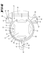
Fig. 2 ; - Fig. 4
- die Draufsicht auf eine Gerätewanne der Küchenmaschine mit hierauf aufgesetztem Aufnahmeteil, unter anderem zur Halterung des Elektromotors;
- Fig. 5
- das Aufnahmeteil mit zuordbarem Elektromotor in perspektivischer Einzeldarstellung;
- Fig. 6
- die Draufsicht auf das Aufnahmeteil;
- Fig. 7
- die Unteransicht gegen das Aufnahmeteil;
- Fig. 8
- eine schematische Perspektivdarstellung eines, ein Wägemodul mit einem Gerätefuß halternden Abschnitts des Aufnahmeteils.
- Fig. 1
- in view of a food processor with an electric motor for driving an agitator in a mixing vessel of the food processor;
- Fig. 2
- the, the electric motor receiving bottom portion of the food processor in partial vertical sectional view;
- Fig. 3
- the enlargement of the area III in
Fig. 2 ; - Fig. 4
- the top view of a device tray of the food processor with attached thereto receiving part, inter alia for holding the electric motor;
- Fig. 5
- the receiving part with assignable electric motor in perspective detail view;
- Fig. 6
- the top view of the receiving part;
- Fig. 7
- the bottom view against the receiving part;
- Fig. 8
- a schematic perspective view of a, a weighing module with a device foot halternden portion of the receiving part.
Dargestellt und beschrieben ist zunächst mit Bezug zu
Des Weiteren verfügt die Küchenmaschine 1 über eine Rührgefäßaufnahme 6. In diese ist ein Rührgefäß 7 insbesondere bevorzugt im Fußbereich desselben formschlüssig aufnehmbar und halterbar. Das Rührgefäß 7 ist bevorzugt im Wesentlichen rotationssymmetrisch ausgebildet, mit einer zentralen Vertikalachse x.Furthermore, the
Im Bodenbereich weist das Rührgefäß 7 bevorzugt ein Rührwerk 8 auf. Dieses ist in der Zuordnungsstellung des Rührgefäßes 7 in der Gefäßaufnahme 6 formschlüssig gekoppelt mit einem in der Küchenmaschine 1 vorgesehenen Motor 9, insbesondere Elektromotor.In the bottom region, the mixing
Die Elektroversorgung des Elektromotors 9 sowie einer weiter bevorzugt behälterbodenseitig vorgesehenen Aufheizeinrichtung und darüber hinaus auch der elektrischen Steuerung der gesamten Küchenmaschine 1 ist über ein Netzanschlusskabel 10 erreicht.The electrical supply of the
Das Rührgefäß 7 ist weiter bevorzugt insbesondere im Betrieb des Rührwerks 8 und/oder der Aufheizeinrichtung durch einen Deckel 11 verschlossen.The agitating
Bei dem Elektromotor 9 handelt es sich bevorzugt um einen Reluktanzmotor, weiter bevorzugt um einen Elektromotor gemäß
Der Elektromotor 9 weist im Wesentlichen einen auf einem Rotorachskörper 12 mit einer Rotorachse aufsteckbaren Rotor auf. Die Rotorachse wird in der Betriebsstellung der Küchenmaschine 1 von deren Vertikalachse x aufgenommen.The
An den Rotorachskörper 12 ist in Betriebsstellung im Bereich eines vertikal unteren Endes ein Lüfterrad drehfest angeordnet, insbesondere an dem Rotor bzw. dem Rotorachskörper 12 angeflanscht. Weiter ist im Wesentlichen Bestandteil des Elektromotors 9 ein Stator 14 mit einem bevorzugt zweiteiligen Statorabdeckkörper zur Aufnahme von Statorspulen, eine Geberscheibe und zwei beidseitig endseitig des Stators 14 an diesem befestigte, die Enden des Rotorachskörpers 12 lagernde Brücken 15, 16. Der Stator 14 umfasst den Rotor vollständig.At the
Der Statorkern des Stators 14 ist im Wesentlichen ringförmig, im Grundriss mehreckig ausgebildet, so in dem dargestellten Ausführungsbeispiel bevorzugt im Wesentlichen in Form eines Achtecks.The stator core of the
Der Elektromotor 9 ist im Wesentlichen bodenseitig in der Küchenmaschine 1 angeordnet, weiter bevorzugt insbesondere innerhalb eines Gerätegehäuses 17.The
Das Gerätegehäuse 17 ist bevorzugt mehrteilig ausgebildet, so im Wesentlichen zweiteilig, hierbei eine den Boden bildende Gehäusewanne 18 und ein als Chassis 19 ausgebildetes, tragendes Gehäuseteil aufweisend.The
Das Chassis 19 umfasst weiter bevorzugt auch die Rührgefäßaufnahme 6.The
Weiter bevorzugt ist der Elektromotor 9 in einem Aufnahmeteil 13 gehaltert. Dieses Aufnahmeteil 13 sitzt in der fertig montierten Stellung der Küchenmaschine 1 bevorzugt nicht durch gesonderte Maßnahmen fixiert auf dem nach innen weisenden Boden 20 der Gehäusewanne 18 auf.More preferably, the
Das Aufnahmeteil 13 ist mit Bezug auf einen Grundriss gemäß
In fertig montierter Stellung der Küchenmaschine 1 ist das Aufnahmeteil 13 von einem deckelartigen Gehäuseabschnitt 22 überfangen, hierbei im Wesentlichen eine in Betriebsstellung horizontal ausgerichtete, den Stator 14 überdeckende Decke ausbildend.In the assembled position of the
Die Decke des Gehäuseabschnittes 22 ist durchsetzt von einem aus dem Stator 14 in Betriebsstellung nach vertikal oben abragenden freien Ende des Rotorachskörpers 12, wobei weiter dieses freie Ende wandungsaußenseitig zur Formschlussmitnahme eines entsprechenden Kupplungsabschnittes des gefäßseitigen Rührwerks 8 profiliert ist.The ceiling of the
In dem Aufnahmeteil 13 ist innenseitig ein zentrales Bauelement 23 eingezogen. Dieses erstreckt sich mit Bezug auf einen Grundriss gemäß
In einem zum Boden 20 vertikal beabstandeten, weiter bevorzugt parallel zu diesem verlaufenden Boden 24 des Bauelements 23 ist die an die umlaufende Kontur der zugeordneten Brücke 15 des Elektromotors 9 angepasste Durchbrechung 21 vorgesehen. Diese ist durchsetzt von der zugeordneten, vertikal unteren Brücke 15, wobei sich der Elektromotor 9 oberseitig unter Zwischenschaltung einer umlaufenden Dichtung 25 mittels des Stators 14 auf dem Boden 24 abstützt. Es ergibt sich entsprechend nur eine strömungsmäßige Verbindung zwischen dem durch das Aufnahmeteil 13 getrennten oberen und unteren Bereich durch das Motorinnere, entsprechend durch den, den Rotorachskörper 12, den Rotor sowie im Wesentlichen das Lüfterrad und vom Stator 14 umgebenden Bereich. Der Elektromotor 9 ist insgesamt in dem Aufnahmeteil 13 befestigt, bevorzugt mittels in
Die Anordnung ist weiter so gewählt, dass die vertikal untere Brücke 15 mit vertikalem Abstand oberhalb des Gerätegehäusebodens 20 sich erstreckt, welcher vertikale Abstand bevorzugt etwa dem halben vertikalen Abstand zwischen Gerätegehäuseboden 20 und Boden 24 des Aufnahmeteils 13 entspricht.The arrangement is further selected so that the vertical
Auch die vertikal nach oben weisende Decke der gegenüberliegenden Brücke 16 ist vertikal beabstandet zu der Decke des oberen Gehäuseabschnittes 22 wobei bevorzugt hier ein vertikaler Abstand gewählt ist, der dem vertikalen Abstand zwischen der unteren Brücke 15 und dem Gerätegehäuseboden 20 im Wesentlichen entspricht.Also, the vertically upwardly facing ceiling of the
Der Boden 24 des zentralen Bauelements 23 geht über in eine den Stator 14 bevorzugt kreisringförmig umgebende, vertikal ausgerichtete Wandung 26. Diese erstreckt sich von dem Boden 24 ausgehend bevorzugt über die gesamte vertikale Höhe des Stators 14. Hieran anschließend erstreckt sich das zentrale Bauelement 23 bevorzugt und im Wesentlichen mit Bezug zu der Rotorachse nach radial außen, insbesondere parallel ausgerichtet zum Boden 24, wobei die so gebildete Trennwand 27 annähernd vollständig umlaufend an der vertikalen Außenwandung 28 des Aufnahmeteiles 13 befestigt, weiter bevorzugt angeformt ist.The
Die Decke des oberen Gehäuseabschnittes 22 sowie weiter bevorzugt die Gehäuseaußenwandung 28 sind wandungsinnenseitig, d.h. dem Elektromotor 9 beziehungsweise dem nachstehend näher beschriebenen Strömungskanälen zugewandt mit einem Schallabsorber-Material 29 versehen. Hierbei handelt es sich bevorzugt um einen offenporigen Schaumstoff, der weiter bevorzugt an den Wandungsabschnitten befestigt, beispielsweise geklebt ist.The ceiling of the
Bevorzugt ausgehend von dem Boden 20 der Gehäusewanne 18 ist weiter bevorzugt eine vertikal gerichtete Strömungsschikane 30 ausgebildet. Diese ist ausgeformt durch eine bevorzugt senkrecht zu dem Boden 20 und somit in Betriebsstellung vertikal ausgerichtete Wandung, welche weiter bevorzugt einstückig und materialeinheitlich mit dem Boden 20 ausgebildet ist.Preferably, starting from the bottom 20 of the
Diese Strömungsschikane 30 umfasst die Vertikalwandung 26 des zentralen Bauelements 23 unter Belassung eines mit Bezug zu der Rotorachse radialen Abstandes vollständig. Die vertikale Höhe der Strömungsschikane 30 ist hierbei so gewählt, dass eine nach radial oben weisende Randkante derselben etwa auf Höhe der halben Vertikalenerstreckung des Stators 14 verläuft. Entsprechend stellt sich neben der radialen Beabstandung zu der Wandung 28 ein vertikaler Abstand zwischen der nach vertikal oben weisenden freien Randkante der Strömungsschikane 30 und der Unterseite der Trennwand 27 ein.This flow baffle 30 completely encloses the
Bevorzugt zu der dem Bedienfeld 2 der Küchenmaschine 1 abgewandten Rückseite der Küchenmaschine 1 hin öffnen sich die durch das zentrale Bauelement 23 getrennten, vertikal übereinanderliegenden Bereiche in einen sich bevorzugt über das Durchmessermaß des kreisringförmigen Abschnitts des Aufnahmeteils 13 erstreckenden Vorraum.Preferably, to the back of the
Der durch das zentrale Bauelement 23 gebildete untere Bereich des Aufnahmeteils 13 formt hier einen Zuströmkanal 31 mit einer quer zur Rotorachse betrachteten Breite, die im Wesentlichen dem Innen-Querstreckungsmaß beziehungsweise Durchmessermaß der Außenwandung 28 entspricht, weiter bevorzugt etwa dem 1,1- bis 1,5-Fachen des größten Quererstreckungsmaßes des Stators 14.The lower region of the receiving
Der Zuströmkanal 31 erstreckt sich ausgehend von einer rückwärtig in der Wandung des Chassis 19 vorgesehenen Einströmöffnung 32 unter Bildung eines radialen Luftweges bis zumindest in axialer Überdeckung zu dem Stator 16.The
In Strömungsrichtung vor der Strömungsschikane 30 ist im Bereich des Bodens 20 eine schanzenartige Erhebung 33 aus dem Boden 20 herausgeformt.In the flow direction in front of the
Die Trennwand 27 des zentralen Bauelements 23 ist in diesem Vorraumbereich unter Bildung des Zuströmkanals 31 im Wesentlichen nach unten in Richtung auf den Boden 20 gerichtet abgewinkelt, hierbei bevorzugt einen spitzen Winkel von 5 bis 15 Grad zu der Vertikalen einschließend, wobei die Trennwand 27 weiter im Bereich des nach unten weisenden Endes der Abwinklung einen bevorzugt parallel zum Boden 20 verlaufenden Bodenabschnitt 34 ausformt. Dieser Bodenabschnitt 34 geht im weiteren Verlauf Richtung Gehäuserückseite wiederum über in einen schräg nach vertikal oben ansteigenden, oberhalb der Einströmöffnung 32 gegen die zugewandte Wandung des Chassis 19 anschließenden Abschnitt.The
Es ergibt sich insgesamt mit Bezug auf die Strömungsrichtung vor der Strömungsschikane 30 ein S-förmig ausgebildeter Abschnitt des Zuströmkanals 31.Overall, with reference to the flow direction upstream of the
Zwischen der bevorzugt konzentrisch zur Rotorachse angeordneten Strömungsschikane 30 und der bevorzugt mit Schallabsorber-Material 29 versehenen, weiter bevorzugt im Wesentlichen umlaufenden Außenwandung 28 des Aufnahmeteiles 13 ist ein ringförmiger Strömungskanal 35 belassen, der sich entsprechend gleichfalls zum Vorraum hin in den dort gebildeten Abschnitt des Zuströmkanals 31 öffnet.Between the preferably arranged concentric to the rotor
Der nach vertikal oben durch die Decke des Gehäuseabschnittes 22 und nach vertikal unten durch die Trennwand 27 begrenzte Bereich formt einen Ausströmkanal 36, der im Wesentlichen gleich gerichtet und entsprechend oberhalb des Zuströmkanals 31 verläuft, weiter entsprechend bevorzugt horizontal und im Wesentlichen in vertikaler Überdeckung zu dem Strömungskanal 35.The region bounded vertically upwards through the ceiling of the
In Strömungsrichtung hinter dem Elektromotor 9, weiter bevorzugt dem Vorraumbereich des Zuströmkanals 31 und entsprechend der Rückseite des Gerätes zugewandt, ist auch hier bevorzugt eine Strömungsschikane 37 vorgesehen.In the flow direction behind the
Diese ist bevorzugt gebildet durch eine am Aufnahmeteil 13 befestigte, im Wesentlichen sich vertikal und somit in einer Parallelebene zur Rotorachse erstreckende Platine 38. Diese Platine 38 trägt bevorzugt Elektronikbauteile, insbesondere zur Steuerung und Regelung des Elektromotors 9. Alternativ ist die Strömungsschikane 37 durch einen bevorzugt in Vertikalrichtung sich erstreckenden Wandungsabschnitt des Gehäuseabschnittes 22 gebildet.This is preferably formed by a mounted on the receiving
Die so gebildete Strömungsschikane 37 erstreckt sich entsprechend bevorzugt ausgehend von der Decke des Gehäuseabschnittes 22 nach vertikal unten bis in den durch die S-förmige Ausgestaltung der Trennwand 27 gebildeten Sickenbereich, dies unter Belassung eines Strömungsweges. Die Strömungsschikane 37 im Ausströmkanal 36 ist entsprechend bevorzugt radial versetzt zu der Strömungsschikane 30 im Zuströmkanal 31, dies weiter bevorzugt in Richtung auf die Geräterückseite.The thus formed
Die Trennwand 27 zwischen dem Zuströmkanal 31 und dem Ausströmkanal 36 bildet entsprechend die Decke des Zuströmkanals 31 und zugleich den Boden des Ausströmkanals 36.The
Zugeordnet der Trennwand 27 ist radial außerhalb der Wandung 26 zwischen dieser und der Außenwandung 28 eine nach oben offene Nut 39 ausgebildet.Associated with the
Im Wesentlichen mit Bezug auf einen Grundriss gemäß
Die drei Ausleger 40 sind weiter bevorzugt so angeordnet, dass diese in einem Grundriss gemäß
Jeder Ausleger 40 weist eine bevorzugt etwa auf halber vertikaler Höhe der Außenwandung 28 sich erstreckende Stellfläche 41 auf. Diese erstreckt sich bevorzugt in Parallelausrichtung zu dem Boden 24 des Aufnahmeteiles 13.Each
Jede Stellfläche 41 ist weiter bevorzugt neben der Außenwandung 28 zusätzlich durch Wandungen 42 umlaufend begrenzt.Each
An jedem Ausleger 40 ist ein Wägemodul 43 befestigt. Dieses Wägemodul 43 weist zunächst einen Waagebalken 44 auf, welcher als sogenannter Halbbalken gestaltet ist. Im Wesentlichen ist der Waagebalken 44 langgestreckt, stabartig ausgeformt mit einem bevorzugt annähernd quadratischen Querschnitt.At each
Bezüglich der weiteren Ausgestaltung des Wägemoduls 43 wird auf die eingangs genannte
In Längserstreckung des Waagebalkens 44 ist dieser zwischen zwei Befestigungsbereichen mit zwei Kerbungen 45 versehen. Diese Kerbungen 45 sind jeweils in eine Vertikalebene des Waagebalkens 44 projiziert, halbkreisförmig gestaltet, wobei weiter die so erreichten, gewölbeförmigen Kerbungen 45 bevorzugt ineinander übergehen derart, dass die so geschaffenen halbscheibenförmigen Kerbungsflächen sich teilweise überlappen.In the longitudinal extension of the
Der Waagebalken 44 ist weiter bevorzugt mit einem unterzugartigen Plattenteil 46 versehen. Hierbei handelt es sich bevorzugt um ein starres Plattenteil, bevorzugt ein Metall-Blechteil. Oberseitig ist ein Dehnungsmessstreifen 53 auf dem Waagebalken 44 angeordnet.The
In vertikaler Überdeckung zu einem Befestigungsbereich des Waagebalkens 44 ist oberseitig des Waagebalkens 44 ein Abstandsteil 47 vorgesehen. Der zugeordnete Befestigungsbereich ist durchsetzt von einer Vertikalbohrung, durch welche eine Schraube 48 zur Festlegung des Waagebalkens 44 an den, die Stellfläche 41 ausbildenden Abschnitt des aufnahmeteilseitigen Auslegers 40 tritt.In vertical overlap to a mounting region of the
Auch der gegenüberliegende, frei auskragende Bereich des Waagebalkens 44 ist mit einer Vertikalbohrung versehen. Diese dient zum Durchsatz einer weiteren Schraube 49 zur Festlegung eines Gerätefußes 50. Der Gerätefuß 50 erstreckt sich hierbei von dem Waagebalken 44 ausgehend nach vertikal unten.Also, the opposite, cantilevered region of the
Die Anordnung der entsprechend der Zahl der Ausleger 40 vorgesehenen drei Gerätefüße 50 ist so gewählt, dass jede geometrische Verbindungslinie a zwischen zwei Gerätefüßen 50, insbesondere zwischen vertikalen Körperachsen der Gerätefüße 50, welche Verbindungslinie a eine Kippachse darstellt, zu einem Geräteschwerpunkt S den gleichen Abstand aufweist. Hierdurch ist ein kippsicheres Aufstellen der Küchenmaschine 1 auf einer Arbeitsfläche 51 ermöglicht.The arrangement of the corresponding number of
Wie insbesondere aus der Darstellung in den
Die Gerätefüße 50 durchsetzen Durchbrechungen 52 im Boden 20 der Gehäusewanne 18, welche Durchbrechungen 52 zumindest einen an dem größten Durchmesser eines Gerätefußes 50 angepassten Öffnungsquerschnitt aufweisen, so dass der Gerätefuß 50 insbesondere in vertikaler Richtung freibeweglich die Gehäusewanne 18 durchsetzen kann.The
Die Gehäusewanne 18 ist unter Beabstandung zu der Arbeitsfläche 51 beziehungsweise unter Beabstandung zu der durch die Stellflächen der Gerätefüße 50 gegebenen Aufstellebene der Küchenmaschine 1 an dem Chassis 19 beziehungsweise an dem sich oberhalb der Gehäusewanne 18 erstreckenden Gehäuseabschnitt angebunden, so beispielsweise mit diesem verklipst oder verschraubt. Das Chassis 19 bildet hierbei unter anderem bevorzugt auch die Rührgefäßaufnahme 6.The
Das gesamte Chassis 19 mitsamt der Gehäusewanne 18 stützt sich über ausgeformte, tragende Elemente 54 auf den Stellflächen 41 der aufnahmeteilseitigen Ausleger 40 ab, wobei das Aufnahmeteil 13 wiederum eine Abstützung auf einer Arbeitsfläche 51 oder dergleichen über die Wägemodule 43 und die hieran angeschlossenen Gerätefüße 50 erfährt.The
Entsprechend wird zumindest das Gewicht des Chassis 19 und der Gehäusewanne 18 über die Wägemodule 43 erfasst, darüber hinaus, wie bevorzugt, im Betrieb der Küchenmaschine 1 auch das Gewicht des Rührgefäßes 7, des in dem Rührgefäß 7 aufgenommenen Inhalts sowie weiterer insbesondere mit dem Rührgefäß 7 beispielsweise zu verbindender Komponenten, wie der Deckel 11 oder auch das Rührwerk 8.Accordingly, at least the weight of the
Die über die Wägemodule 43 erfassten Gewichtswerte werden, bevorzugt unter Herausrechnen des Eigengewichts der auf die Wägemodule 43 einwirkenden Komponenten, in dem Display 5 angezeigt.The weight values recorded via the weighing
Der Gerätekraftfluss wandert von den Gerätefüßen 50 über die zugeordneten Wägemodule 43 bevorzugt direkt durch die tragenden Elemente 54 des Chassis 19. Somit bleibt das Aufnahmeteil 13 aus dem Kraftfluss, braucht entsprechend keine gesonderten Festigkeitsanforderungen erfüllen.The device power flow preferably moves from the
Die Wägemodule 43 sowie die hieran angeschlossenen Gerätefüße 50 sind in bevorzugter Ausgestaltung zur Montage der Küchenmaschine 1 bereits an dem Aufnahmeteil 13 festgelegt. Darüber hinaus auch eine Verkabelung 55 der Wägemodule 43, welche Verkabelung 55 weiter bevorzugt in der Nut 39 des Aufnahmeteiles 13 aufgenommen ist.The weighing
Bevorzugt sind die elektrischen Anschlüsse der Verkabelung 55 aller Wägemodule 43 in einem Sammelstecker 56 zusammengeführt. Der Sammelstecker 56 ist weiter bevorzugt an dem Aufnahmeteil 13 befestigt, so bspw. im Bereich der Nut 39.Preferably, the electrical connections of the
Wie schematisch insbesondere in
Das so bevorzugt gestaltete Aufnahmeteil 13 stellt entsprechend ein Wäge-Sammelmodul dar, welches weiter bevorzugt zugleich der Halterung des Motors 9 dient und/oder eine Luftführung zur Kühlung des Motors 9 ausbildet.The so preferably designed receiving
Zur Montage der Küchenmaschine 1 wird in bevorzugter Ausgestaltung zunächst die Gehäusewanne 18 beispielsweise auf einer Arbeitsfläche 51 abgelegt. Die weitere Montage der einzelnen Gerätekomponenten erfolgt bevorzugt grundsätzlich von oben, d.h. in Richtung auf das Wanneninnere.For mounting the
So wird bevorzugt zunächst das vorbereitete Aufnahmeteil 13 in die Gehäusewanne 18 eingesetzt, dies unter Durchtauchen der aufnahmeteilseitigen Gerätefüße 50 durch die Durchbrechungen 52 der Gehäusewanne 18, welche Gerätefüße 50 entsprechend sich auf derselben Arbeitsfläche 51 abstützen wie die Gehäusewanne 18.Thus, the prepared receiving
Hiernach erfolgt bevorzugt die Anordnung der weiteren Gerätekomponenten, insbesondere des Motors 9 und des Chassis 19, wobei weiter im Zuge dieses Aufsetzens der weiteren Komponenten bevorzugt auch die elektrische Kontaktierung insbesondere des Motors 9, darüber hinaus auch bevorzugt des Wäge-Sammelsteckers 56 erfolgt.Thereafter, preferably the arrangement of the other device components, in particular of the
Sodann wird - gegebenenfalls abschließend - die Gehäusewanne 18, bevorzugt unter paralleler Beabstandung des Bodens 20 der Gehäusewanne 18 zur Arbeitsfläche 51 angehoben, welches Anheben die entsprechend ausgebildeten Durchbrechungen 52 erlauben. In der angehobenen Stellung wird die Gehäusewanne 18 mit dem Chassis 19 verbunden.Then - if necessary finally - the
Eine Demontage der Küchenmaschine 1 erfolgt bevorzugt in umgekehrter Reihenfolge, weiter bevorzugt beginnend mit einem Lösen der Gehäusewanne 18 vom Chassis 19 und Absenken der Gehäusewanne 18 auf die Arbeitsfläche 51.Disassembly of the
Insbesondere durch die Anordnung des Aufnahmeteiles 13 von oben in die Gehäusewanne 18 werden durch das Aufnahmeteil 13, insbesondere durch Abschnitte des Aufnahmeteiles 13, gegebenenfalls notwendige Montageöffnungen in der Gehäusewanne 18 verschlossen.In particular, by the arrangement of the receiving
Alle offenbarten Merkmale sind (für sich) erfindungswesentlich. In die Offenbarung der Anmeldung wird hiermit auch der Offenbarungsinhalt der zugehörigen/beigefügten Prioritätsunterlagen (Abschrift der Voranmeldung) vollinhaltlich mit einbezogen, auch zu dem Zweck, Merkmale dieser Unterlagen in Ansprüche vorliegender Anmeldung mit aufzunehmen. Die Unteransprüche charakterisieren in ihrer fakultativ nebengeordneten Fassung eigenständige erfinderische Weiterbildungen des Standes der Technik, insbesondere um auf Basis dieser Ansprüche Teilanmeldungen vorzunehmen.
Claims (9)
Applications Claiming Priority (1)
| Application Number | Priority Date | Filing Date | Title |
|---|---|---|---|
| DE102012104495A DE102012104495A1 (en) | 2012-05-24 | 2012-05-24 | Food processor with a mixing vessel and method for assembling a food processor |
Publications (2)
| Publication Number | Publication Date |
|---|---|
| EP2666397A1 true EP2666397A1 (en) | 2013-11-27 |
| EP2666397B1 EP2666397B1 (en) | 2016-06-22 |
Family
ID=48366213
Family Applications (1)
| Application Number | Title | Priority Date | Filing Date |
|---|---|---|---|
| EP13167279.2A Active EP2666397B1 (en) | 2012-05-24 | 2013-05-10 | Kitchen appliance with a mixing bowl and method for installing the same |
Country Status (6)
| Country | Link |
|---|---|
| EP (1) | EP2666397B1 (en) |
| CN (1) | CN103417138B (en) |
| DE (1) | DE102012104495A1 (en) |
| ES (1) | ES2586834T3 (en) |
| PL (1) | PL2666397T3 (en) |
| PT (1) | PT2666397T (en) |
Cited By (1)
| Publication number | Priority date | Publication date | Assignee | Title |
|---|---|---|---|---|
| EP3170433A1 (en) * | 2015-11-18 | 2017-05-24 | Whirlpool Corporation | Coffee grinder with integrated scale |
Families Citing this family (2)
| Publication number | Priority date | Publication date | Assignee | Title |
|---|---|---|---|---|
| CN107836980A (en) * | 2016-09-20 | 2018-03-27 | 深圳市联创三金电器有限公司 | Multifunctional food processing unit |
| DE102017123690A1 (en) * | 2017-10-11 | 2019-04-11 | Vorwerk & Co. Interholding Gmbh | Electromotive operated food processor and mixing vessel and agitator for it |
Citations (9)
| Publication number | Priority date | Publication date | Assignee | Title |
|---|---|---|---|---|
| EP0561259A1 (en) * | 1992-03-16 | 1993-09-22 | Braun Aktiengesellschaft | Food processor with weighing device |
| DE10219442A1 (en) | 2002-05-02 | 2003-11-20 | Mann & Hummel Filter | connector |
| DE102008040741A1 (en) * | 2008-07-25 | 2010-01-28 | BSH Bosch und Siemens Hausgeräte GmbH | Food processor with a trained base with several feet |
| DE102008040740A1 (en) * | 2008-07-25 | 2010-01-28 | BSH Bosch und Siemens Hausgeräte GmbH | Kitchen appliance, has bases arranged at base part for positioning appliance on subsurface, and weighing device comprising weighing modules, where modules comprise weight sensor partially arranged in bases |
| EP1656724B1 (en) | 2003-08-18 | 2011-04-20 | Vorwerk & Co. Interholding GmbH | Reluctance motor |
| DE102010060650A1 (en) * | 2009-11-25 | 2011-05-26 | Vorwerk & Co. Interholding Gmbh | food processor |
| DE102009058258A1 (en) * | 2009-12-10 | 2011-06-16 | Vorwerk & Co. Interholding Gmbh | food processor |
| DE102009059242A1 (en) | 2009-12-21 | 2011-06-22 | Vorwerk & Co. Interholding GmbH, 42275 | Weighing cell for use in kitchen balance of food processor utilized for preparing food, has plate part attached to scale beams at notch side and provided with constant thickness over length between fastening areas |
| DE102009059294A1 (en) | 2009-12-23 | 2011-06-30 | ACO Severin Ahlmann GmbH & Co. KG, 24768 | Device and method for insulating a component wall and insulated wall structure |
Family Cites Families (1)
| Publication number | Priority date | Publication date | Assignee | Title |
|---|---|---|---|---|
| DE102008027353A1 (en) * | 2008-06-07 | 2009-12-10 | Vorwerk & Co. Interholding Gmbh | Food processor with a mixing vessel |
-
2012
- 2012-05-24 DE DE102012104495A patent/DE102012104495A1/en not_active Withdrawn
-
2013
- 2013-05-10 EP EP13167279.2A patent/EP2666397B1/en active Active
- 2013-05-10 PT PT131672792T patent/PT2666397T/en unknown
- 2013-05-10 PL PL13167279.2T patent/PL2666397T3/en unknown
- 2013-05-10 ES ES13167279.2T patent/ES2586834T3/en active Active
- 2013-05-24 CN CN201310323030.1A patent/CN103417138B/en active Active
Patent Citations (9)
| Publication number | Priority date | Publication date | Assignee | Title |
|---|---|---|---|---|
| EP0561259A1 (en) * | 1992-03-16 | 1993-09-22 | Braun Aktiengesellschaft | Food processor with weighing device |
| DE10219442A1 (en) | 2002-05-02 | 2003-11-20 | Mann & Hummel Filter | connector |
| EP1656724B1 (en) | 2003-08-18 | 2011-04-20 | Vorwerk & Co. Interholding GmbH | Reluctance motor |
| DE102008040741A1 (en) * | 2008-07-25 | 2010-01-28 | BSH Bosch und Siemens Hausgeräte GmbH | Food processor with a trained base with several feet |
| DE102008040740A1 (en) * | 2008-07-25 | 2010-01-28 | BSH Bosch und Siemens Hausgeräte GmbH | Kitchen appliance, has bases arranged at base part for positioning appliance on subsurface, and weighing device comprising weighing modules, where modules comprise weight sensor partially arranged in bases |
| DE102010060650A1 (en) * | 2009-11-25 | 2011-05-26 | Vorwerk & Co. Interholding Gmbh | food processor |
| DE102009058258A1 (en) * | 2009-12-10 | 2011-06-16 | Vorwerk & Co. Interholding Gmbh | food processor |
| DE102009059242A1 (en) | 2009-12-21 | 2011-06-22 | Vorwerk & Co. Interholding GmbH, 42275 | Weighing cell for use in kitchen balance of food processor utilized for preparing food, has plate part attached to scale beams at notch side and provided with constant thickness over length between fastening areas |
| DE102009059294A1 (en) | 2009-12-23 | 2011-06-30 | ACO Severin Ahlmann GmbH & Co. KG, 24768 | Device and method for insulating a component wall and insulated wall structure |
Cited By (2)
| Publication number | Priority date | Publication date | Assignee | Title |
|---|---|---|---|---|
| EP3170433A1 (en) * | 2015-11-18 | 2017-05-24 | Whirlpool Corporation | Coffee grinder with integrated scale |
| US10317274B2 (en) | 2015-11-18 | 2019-06-11 | Whirlpool Corporation | Coffee grinder with integrated scale |
Also Published As
| Publication number | Publication date |
|---|---|
| EP2666397B1 (en) | 2016-06-22 |
| DE102012104495A1 (en) | 2013-11-28 |
| PL2666397T3 (en) | 2016-10-31 |
| CN103417138A (en) | 2013-12-04 |
| ES2586834T3 (en) | 2016-10-19 |
| PT2666397T (en) | 2016-08-26 |
| CN103417138B (en) | 2017-07-21 |
Similar Documents
| Publication | Publication Date | Title |
|---|---|---|
| EP2666397B1 (en) | Kitchen appliance with a mixing bowl and method for installing the same | |
| DE102010017335A1 (en) | Food processor with a mixing vessel and method for operating such a food processor | |
| DE102008055017B4 (en) | dishwasher | |
| DE2053861A1 (en) | Drive unit for household appliances for mixing food | |
| DE102004056708A1 (en) | Seat drive motor and seat drive system | |
| EP3092936B1 (en) | Dishwasher | |
| DE102017101168A1 (en) | Hob with integrated accessories for the preparation of food | |
| CH680617A5 (en) | ||
| EP2818742A2 (en) | Built-in part, for example of a kitchen appliance and kitchen appliance with a mixing vessel | |
| DE202021104355U1 (en) | Leg structure of an electric table | |
| DE102007034818A1 (en) | Platform system to operate as a rotating/navigable device adapts to a wide range of uses as a piece of furniture, a desk, an office tool or a piece of kitchen furniture | |
| EP2754824A2 (en) | Revolving door with a drive unit fixed to a glass cover element | |
| DE102009031990A1 (en) | Device, in particular food processor | |
| DE102013203261A1 (en) | Electric slicing machine for cutting slices of e.g. strand-like food, with cutting device, has machine housing including tower-shaped portion provided with opening to storage area, and central tray system suspended in machine housing | |
| DE2144372A1 (en) | Magnetically driven stirrer - with easily inserted heater between drive and stirrer | |
| DE202019104969U1 (en) | Cooking appliance | |
| DE102012101757A1 (en) | Electric motor for use in electrically operated food processor, has stator, where air flows through motor interior on stator inner side in flow direction and radially and outwardly disperses above stator and/or rotor | |
| DE202005000557U1 (en) | Mobile garden grill has two box elements with connecting elements opening out at front to provide access to cooking units on top side | |
| EP1080677A1 (en) | Electric grill | |
| DE202008011881U1 (en) | Breadmaker with hidden heating element | |
| EP3943817B1 (en) | Range | |
| DE60006732T2 (en) | Rotating knife | |
| DE102014100515A1 (en) | Electric motor driven food processor | |
| EP3481513A1 (en) | Device body for a strength training device, for flexible use | |
| DE3931548C2 (en) |
Legal Events
| Date | Code | Title | Description |
|---|---|---|---|
| PUAI | Public reference made under article 153(3) epc to a published international application that has entered the european phase |
Free format text: ORIGINAL CODE: 0009012 |
|
| AK | Designated contracting states |
Kind code of ref document: A1 Designated state(s): AL AT BE BG CH CY CZ DE DK EE ES FI FR GB GR HR HU IE IS IT LI LT LU LV MC MK MT NL NO PL PT RO RS SE SI SK SM TR |
|
| AX | Request for extension of the european patent |
Extension state: BA ME |
|
| 17P | Request for examination filed |
Effective date: 20140509 |
|
| RBV | Designated contracting states (corrected) |
Designated state(s): AL AT BE BG CH CY CZ DE DK EE ES FI FR GB GR HR HU IE IS IT LI LT LU LV MC MK MT NL NO PL PT RO RS SE SI SK SM TR |
|
| RIC1 | Information provided on ipc code assigned before grant |
Ipc: A47J 43/04 20060101AFI20141105BHEP Ipc: A47J 43/07 20060101ALI20141105BHEP Ipc: A47J 43/046 20060101ALI20141105BHEP |
|
| 17Q | First examination report despatched |
Effective date: 20141117 |
|
| GRAP | Despatch of communication of intention to grant a patent |
Free format text: ORIGINAL CODE: EPIDOSNIGR1 |
|
| INTG | Intention to grant announced |
Effective date: 20160127 |
|
| GRAS | Grant fee paid |
Free format text: ORIGINAL CODE: EPIDOSNIGR3 |
|
| GRAA | (expected) grant |
Free format text: ORIGINAL CODE: 0009210 |
|
| STAA | Information on the status of an ep patent application or granted ep patent |
Free format text: STATUS: THE PATENT HAS BEEN GRANTED |
|
| AK | Designated contracting states |
Kind code of ref document: B1 Designated state(s): AL AT BE BG CH CY CZ DE DK EE ES FI FR GB GR HR HU IE IS IT LI LT LU LV MC MK MT NL NO PL PT RO RS SE SI SK SM TR |
|
| REG | Reference to a national code |
Ref country code: GB Ref legal event code: FG4D Free format text: NOT ENGLISH |
|
| REG | Reference to a national code |
Ref country code: CH Ref legal event code: EP |
|
| REG | Reference to a national code |
Ref country code: IE Ref legal event code: FG4D Free format text: LANGUAGE OF EP DOCUMENT: GERMAN |
|
| REG | Reference to a national code |
Ref country code: AT Ref legal event code: REF Ref document number: 807152 Country of ref document: AT Kind code of ref document: T Effective date: 20160715 |
|
| REG | Reference to a national code |
Ref country code: DE Ref legal event code: R096 Ref document number: 502013003442 Country of ref document: DE |
|
| REG | Reference to a national code |
Ref country code: PT Ref legal event code: SC4A Ref document number: 2666397 Country of ref document: PT Date of ref document: 20160826 Kind code of ref document: T Free format text: AVAILABILITY OF NATIONAL TRANSLATION Effective date: 20160819 |
|
| REG | Reference to a national code |
Ref country code: ES Ref legal event code: FG2A Ref document number: 2586834 Country of ref document: ES Kind code of ref document: T3 Effective date: 20161019 |
|
| REG | Reference to a national code |
Ref country code: LT Ref legal event code: MG4D |
|
| REG | Reference to a national code |
Ref country code: NL Ref legal event code: MP Effective date: 20160622 |
|
| PG25 | Lapsed in a contracting state [announced via postgrant information from national office to epo] |
Ref country code: FI Free format text: LAPSE BECAUSE OF FAILURE TO SUBMIT A TRANSLATION OF THE DESCRIPTION OR TO PAY THE FEE WITHIN THE PRESCRIBED TIME-LIMIT Effective date: 20160622 Ref country code: LT Free format text: LAPSE BECAUSE OF FAILURE TO SUBMIT A TRANSLATION OF THE DESCRIPTION OR TO PAY THE FEE WITHIN THE PRESCRIBED TIME-LIMIT Effective date: 20160622 Ref country code: NO Free format text: LAPSE BECAUSE OF FAILURE TO SUBMIT A TRANSLATION OF THE DESCRIPTION OR TO PAY THE FEE WITHIN THE PRESCRIBED TIME-LIMIT Effective date: 20160922 |
|
| PG25 | Lapsed in a contracting state [announced via postgrant information from national office to epo] |
Ref country code: SE Free format text: LAPSE BECAUSE OF FAILURE TO SUBMIT A TRANSLATION OF THE DESCRIPTION OR TO PAY THE FEE WITHIN THE PRESCRIBED TIME-LIMIT Effective date: 20160622 Ref country code: HR Free format text: LAPSE BECAUSE OF FAILURE TO SUBMIT A TRANSLATION OF THE DESCRIPTION OR TO PAY THE FEE WITHIN THE PRESCRIBED TIME-LIMIT Effective date: 20160622 Ref country code: RS Free format text: LAPSE BECAUSE OF FAILURE TO SUBMIT A TRANSLATION OF THE DESCRIPTION OR TO PAY THE FEE WITHIN THE PRESCRIBED TIME-LIMIT Effective date: 20160622 Ref country code: GR Free format text: LAPSE BECAUSE OF FAILURE TO SUBMIT A TRANSLATION OF THE DESCRIPTION OR TO PAY THE FEE WITHIN THE PRESCRIBED TIME-LIMIT Effective date: 20160923 Ref country code: NL Free format text: LAPSE BECAUSE OF FAILURE TO SUBMIT A TRANSLATION OF THE DESCRIPTION OR TO PAY THE FEE WITHIN THE PRESCRIBED TIME-LIMIT Effective date: 20160622 Ref country code: LV Free format text: LAPSE BECAUSE OF FAILURE TO SUBMIT A TRANSLATION OF THE DESCRIPTION OR TO PAY THE FEE WITHIN THE PRESCRIBED TIME-LIMIT Effective date: 20160622 |
|
| PG25 | Lapsed in a contracting state [announced via postgrant information from national office to epo] |
Ref country code: SK Free format text: LAPSE BECAUSE OF FAILURE TO SUBMIT A TRANSLATION OF THE DESCRIPTION OR TO PAY THE FEE WITHIN THE PRESCRIBED TIME-LIMIT Effective date: 20160622 Ref country code: EE Free format text: LAPSE BECAUSE OF FAILURE TO SUBMIT A TRANSLATION OF THE DESCRIPTION OR TO PAY THE FEE WITHIN THE PRESCRIBED TIME-LIMIT Effective date: 20160622 Ref country code: CZ Free format text: LAPSE BECAUSE OF FAILURE TO SUBMIT A TRANSLATION OF THE DESCRIPTION OR TO PAY THE FEE WITHIN THE PRESCRIBED TIME-LIMIT Effective date: 20160622 Ref country code: RO Free format text: LAPSE BECAUSE OF FAILURE TO SUBMIT A TRANSLATION OF THE DESCRIPTION OR TO PAY THE FEE WITHIN THE PRESCRIBED TIME-LIMIT Effective date: 20160622 Ref country code: IS Free format text: LAPSE BECAUSE OF FAILURE TO SUBMIT A TRANSLATION OF THE DESCRIPTION OR TO PAY THE FEE WITHIN THE PRESCRIBED TIME-LIMIT Effective date: 20161022 |
|
| PG25 | Lapsed in a contracting state [announced via postgrant information from national office to epo] |
Ref country code: SM Free format text: LAPSE BECAUSE OF FAILURE TO SUBMIT A TRANSLATION OF THE DESCRIPTION OR TO PAY THE FEE WITHIN THE PRESCRIBED TIME-LIMIT Effective date: 20160622 |
|
| REG | Reference to a national code |
Ref country code: DE Ref legal event code: R097 Ref document number: 502013003442 Country of ref document: DE |
|
| PLBE | No opposition filed within time limit |
Free format text: ORIGINAL CODE: 0009261 |
|
| STAA | Information on the status of an ep patent application or granted ep patent |
Free format text: STATUS: NO OPPOSITION FILED WITHIN TIME LIMIT |
|
| REG | Reference to a national code |
Ref country code: FR Ref legal event code: PLFP Year of fee payment: 5 |
|
| 26N | No opposition filed |
Effective date: 20170323 |
|
| PG25 | Lapsed in a contracting state [announced via postgrant information from national office to epo] |
Ref country code: DK Free format text: LAPSE BECAUSE OF FAILURE TO SUBMIT A TRANSLATION OF THE DESCRIPTION OR TO PAY THE FEE WITHIN THE PRESCRIBED TIME-LIMIT Effective date: 20160622 |
|
| PG25 | Lapsed in a contracting state [announced via postgrant information from national office to epo] |
Ref country code: SI Free format text: LAPSE BECAUSE OF FAILURE TO SUBMIT A TRANSLATION OF THE DESCRIPTION OR TO PAY THE FEE WITHIN THE PRESCRIBED TIME-LIMIT Effective date: 20160622 Ref country code: LU Free format text: LAPSE BECAUSE OF NON-PAYMENT OF DUE FEES Effective date: 20170531 |
|
| REG | Reference to a national code |
Ref country code: CH Ref legal event code: PL |
|
| PG25 | Lapsed in a contracting state [announced via postgrant information from national office to epo] |
Ref country code: MC Free format text: LAPSE BECAUSE OF FAILURE TO SUBMIT A TRANSLATION OF THE DESCRIPTION OR TO PAY THE FEE WITHIN THE PRESCRIBED TIME-LIMIT Effective date: 20160622 |
|
| REG | Reference to a national code |
Ref country code: IE Ref legal event code: MM4A |
|
| PG25 | Lapsed in a contracting state [announced via postgrant information from national office to epo] |
Ref country code: LI Free format text: LAPSE BECAUSE OF NON-PAYMENT OF DUE FEES Effective date: 20170531 Ref country code: CH Free format text: LAPSE BECAUSE OF NON-PAYMENT OF DUE FEES Effective date: 20170531 |
|
| PG25 | Lapsed in a contracting state [announced via postgrant information from national office to epo] |
Ref country code: LU Free format text: LAPSE BECAUSE OF NON-PAYMENT OF DUE FEES Effective date: 20170510 |
|
| REG | Reference to a national code |
Ref country code: BE Ref legal event code: MM Effective date: 20170531 |
|
| PG25 | Lapsed in a contracting state [announced via postgrant information from national office to epo] |
Ref country code: IE Free format text: LAPSE BECAUSE OF NON-PAYMENT OF DUE FEES Effective date: 20170510 |
|
| REG | Reference to a national code |
Ref country code: FR Ref legal event code: PLFP Year of fee payment: 6 |
|
| PG25 | Lapsed in a contracting state [announced via postgrant information from national office to epo] |
Ref country code: BE Free format text: LAPSE BECAUSE OF NON-PAYMENT OF DUE FEES Effective date: 20170531 |
|
| PG25 | Lapsed in a contracting state [announced via postgrant information from national office to epo] |
Ref country code: MT Free format text: LAPSE BECAUSE OF FAILURE TO SUBMIT A TRANSLATION OF THE DESCRIPTION OR TO PAY THE FEE WITHIN THE PRESCRIBED TIME-LIMIT Effective date: 20160622 |
|
| PG25 | Lapsed in a contracting state [announced via postgrant information from national office to epo] |
Ref country code: AL Free format text: LAPSE BECAUSE OF FAILURE TO SUBMIT A TRANSLATION OF THE DESCRIPTION OR TO PAY THE FEE WITHIN THE PRESCRIBED TIME-LIMIT Effective date: 20160622 |
|
| PG25 | Lapsed in a contracting state [announced via postgrant information from national office to epo] |
Ref country code: HU Free format text: LAPSE BECAUSE OF FAILURE TO SUBMIT A TRANSLATION OF THE DESCRIPTION OR TO PAY THE FEE WITHIN THE PRESCRIBED TIME-LIMIT; INVALID AB INITIO Effective date: 20130510 |
|
| REG | Reference to a national code |
Ref country code: AT Ref legal event code: MM01 Ref document number: 807152 Country of ref document: AT Kind code of ref document: T Effective date: 20180510 |
|
| PG25 | Lapsed in a contracting state [announced via postgrant information from national office to epo] |
Ref country code: BG Free format text: LAPSE BECAUSE OF FAILURE TO SUBMIT A TRANSLATION OF THE DESCRIPTION OR TO PAY THE FEE WITHIN THE PRESCRIBED TIME-LIMIT Effective date: 20160622 |
|
| PG25 | Lapsed in a contracting state [announced via postgrant information from national office to epo] |
Ref country code: CY Free format text: LAPSE BECAUSE OF NON-PAYMENT OF DUE FEES Effective date: 20160622 Ref country code: AT Free format text: LAPSE BECAUSE OF NON-PAYMENT OF DUE FEES Effective date: 20180510 |
|
| PG25 | Lapsed in a contracting state [announced via postgrant information from national office to epo] |
Ref country code: MK Free format text: LAPSE BECAUSE OF FAILURE TO SUBMIT A TRANSLATION OF THE DESCRIPTION OR TO PAY THE FEE WITHIN THE PRESCRIBED TIME-LIMIT Effective date: 20160622 |
|
| PGFP | Annual fee paid to national office [announced via postgrant information from national office to epo] |
Ref country code: TR Payment date: 20200508 Year of fee payment: 8 |
|
| P01 | Opt-out of the competence of the unified patent court (upc) registered |
Effective date: 20230517 |
|
| PGFP | Annual fee paid to national office [announced via postgrant information from national office to epo] |
Ref country code: PT Payment date: 20230503 Year of fee payment: 11 Ref country code: IT Payment date: 20230531 Year of fee payment: 11 Ref country code: FR Payment date: 20230517 Year of fee payment: 11 Ref country code: ES Payment date: 20230621 Year of fee payment: 11 Ref country code: DE Payment date: 20230519 Year of fee payment: 11 |
|
| PGFP | Annual fee paid to national office [announced via postgrant information from national office to epo] |
Ref country code: PL Payment date: 20230504 Year of fee payment: 11 |
|
| PGFP | Annual fee paid to national office [announced via postgrant information from national office to epo] |
Ref country code: GB Payment date: 20230522 Year of fee payment: 11 |