DE102009059242A1 - Weighing cell for use in kitchen balance of food processor utilized for preparing food, has plate part attached to scale beams at notch side and provided with constant thickness over length between fastening areas - Google Patents
Weighing cell for use in kitchen balance of food processor utilized for preparing food, has plate part attached to scale beams at notch side and provided with constant thickness over length between fastening areas Download PDFInfo
- Publication number
- DE102009059242A1 DE102009059242A1 DE102009059242A DE102009059242A DE102009059242A1 DE 102009059242 A1 DE102009059242 A1 DE 102009059242A1 DE 102009059242 A DE102009059242 A DE 102009059242A DE 102009059242 A DE102009059242 A DE 102009059242A DE 102009059242 A1 DE102009059242 A1 DE 102009059242A1
- Authority
- DE
- Germany
- Prior art keywords
- balance beam
- plate part
- load cell
- notches
- balance
- Prior art date
- Legal status (The legal status is an assumption and is not a legal conclusion. Google has not performed a legal analysis and makes no representation as to the accuracy of the status listed.)
- Withdrawn
Links
Images


Classifications
-
- G—PHYSICS
- G01—MEASURING; TESTING
- G01G—WEIGHING
- G01G19/00—Weighing apparatus or methods adapted for special purposes not provided for in the preceding groups
- G01G19/52—Weighing apparatus combined with other objects, e.g. furniture
- G01G19/56—Weighing apparatus combined with other objects, e.g. furniture combined with handles of tools or household implements
-
- G—PHYSICS
- G01—MEASURING; TESTING
- G01G—WEIGHING
- G01G3/00—Weighing apparatus characterised by the use of elastically-deformable members, e.g. spring balances
- G01G3/12—Weighing apparatus characterised by the use of elastically-deformable members, e.g. spring balances wherein the weighing element is in the form of a solid body stressed by pressure or tension during weighing
- G01G3/14—Weighing apparatus characterised by the use of elastically-deformable members, e.g. spring balances wherein the weighing element is in the form of a solid body stressed by pressure or tension during weighing measuring variations of electrical resistance
- G01G3/1402—Special supports with preselected places to mount the resistance strain gauges; Mounting of supports
Abstract
Description
Die Erfindung betrifft eine Wägezelle für eine elektrische Waage, mit einem Waagebalken, der beidseitig zur Befestigung oder Anordnung an gegeneinander beweglichen Teilen einer Vorrichtung ausgebildet ist und zwischen den Befestigungsbereichen eine oder mehrere Kerbungen aufweist, zur Erzielung vergleichsweise hoher Verformung bei Belastung.The invention relates to a load cell for an electrical balance, with a balance beam, which is formed on both sides for attachment or arrangement of mutually movable parts of a device and between the attachment regions has one or more notches, to achieve relatively high deformation under load.
Die Ausgestaltung von Waagebalken für Wägezellen ist vielfältig und grundsätzlich den Erfordernissen der Messaufgabe und dem zur Verfügung stehenden Bauraum angepasst. Die Grundform des Balkens entspricht dem mechanischen Modell eines Vierkant-Balkens, der an einer Seite eingespannt ist und an seinem freien Ende durch Kraft belastet wird. Dementsprechend verbiegt sich der Balken in direkter Abhängigkeit des wirksamen Hebelarmes zwischen Einspannung und Kraftangriffspunkt. Mit wachsendem Abstand zur Einspannung nimmt die Verbiegung zu. In einem regulären Vollmaterialbalken verteilen sich die Spannungen und Dehnungen über die gesamte Balkenfläche. Durch vorgesehene Kerbungen, bevorzugt zwei große, parallele Kerbungen des Balkens in Querrichtung, können die Spannungen lokalisiert werden, d. h. an den gewünschten Messstellen konzentriert werden. Dies erhöht das Messsignal im Kerbbereich signifikant, da im Bereich der Kerbung zufolge Materialschwächung des Waagebalkens im Vergleich zum nicht geschwächten, gleichfalls frei auskragenden Balkenbereich außerhalb der Kerbzonen eine erhöhte Verformung erreicht wird. Gleichzeitig ist der Biegeweg des Balkens allerdings von der verbleibenden minimalen Wandstärke über den Einkerbungen abhängig. Eine weitere Verbesserung der Wägezelle stellt ein Kraftrückführungsarm dar. Dieser wird am freien Ende des Balkens angebunden und führt die Krafteinleitung parallel zum Balken zurück bis unter die Messstelle. Auf diese Weise wird durch den verkleinerten Hebelarm die Verbiegung reduziert und zusätzlich die Spannungsverteilung positiv beeinflusst. Hat der freie Balken eine reine Verteilung von Zug- oder Druckspannungen auf einer Seite, so ergeben sich zu beiden Seiten der Krafteinleitung abwechselnd Zug- und Druckspannungen. Alternativ zur Anbindung eines separaten Kraftrückführungsarms ist es weiter bekannt, diesen in die Geometrie des Balkens zu integrieren, so dass sich eine einteilige Ausgestaltung ohne Fügestellen und Materialübergänge ergibt. Eine weitere, verbreitete Ausgestaltung des Waagebalkens ist der Doppelbalken mit Parallelogrammlenker. Dieser ist im Allgemeinen höher als der einfache Waagebalken und ist anstatt mit ausgeprägten Kerbungen in Querrichtung mit Bohrungen versehen. Auf diese Weise entstehen am höchsten und am tiefsten Punkt der Bohrungen erneut Lokalisierungen der Spannungen und Dehnungen. Ähnlich wie durch den Kraftrückführungsarm wird durch den Parallelogrammlenker keine reine Verbiegung des Balkens in einer Parabelkurve erzeugt, sondern eine S-förmige Verformung, die erneut eine Mischung aus Zug- und Druckspannungen in den Messstellen erzeugt. Der Doppelbiegebalken kombiniert eine geringe Verformung mit einem hohen Ausgangssignal, ist aber verhältnismäßig aufwändig und kostenintensiv in der Herstellung.The design of balance beam for load cells is diverse and basically adapted to the requirements of the measurement task and the available space. The basic form of the beam corresponds to the mechanical model of a square beam, which is clamped on one side and loaded at its free end by force. Accordingly, the beam bends in direct dependence of the effective lever arm between restraint and force application point. With increasing distance to the clamping, the bending increases. In a regular solid material beam, the stresses and strains spread over the entire beam surface. By provided notches, preferably two large, parallel notches of the beam in the transverse direction, the stresses can be localized, i. H. be concentrated at the desired measuring points. This significantly increases the measuring signal in the notch area, since in the region of the notch, material weakening of the balance beam results in increased deformation compared to the undeflected, likewise cantilevered beam area outside the notch zones. At the same time, however, the bending path of the beam depends on the remaining minimum wall thickness above the notches. A further improvement in the load cell is a force return arm. This is connected to the free end of the beam and returns the force parallel to the beam back to below the measuring point. In this way, the reduced lever arm reduces the bending and additionally positively influences the stress distribution. If the free beam has a pure distribution of tensile or compressive stresses on one side, tensile and compressive stresses occur alternately on both sides of the force introduction. As an alternative to the connection of a separate force return arm, it is also known to integrate this in the geometry of the beam, so that there is a one-piece design without joints and material transitions. Another widespread embodiment of the balance beam is the double beam with parallelogram link. This is generally higher than the simple balance beam and has holes in the transverse direction instead of pronounced notches. In this way, localizations of stresses and strains occur again at the highest and lowest point of the holes. Similar to the force feedback arm, the parallelogram link does not produce a pure bending of the beam in a parabolic curve, but rather an S-shaped deformation which again produces a mixture of tensile and compressive stresses in the measuring points. The double bending beam combines a low deformation with a high output signal, but is relatively expensive and expensive to manufacture.
Bei einem einfachen Waagebalken erweist sich die sehr hohe längenbezogene Verformung als nachteilig. Dies führt zu einer hohen Materialbelastung. Hinzu kommt die starke Hebelarmabhängigkeit der Krafteinleitung, die das Messergebnis bereits bei geringen Abweichungen der Position der Krafteinleitung verändert, sowie die verbleibende Empfindlichkeit gegen Querkräfte. Erst der Einsatz eines Kraftrückführungsarmes verringert diese Einflüsse. Die Verformung wird durch den zurückgesetzten Krafteinleitungspunkt gesenkt. Das Ausgangssignal wird durch die Kombination aus Zug- und Druckspannungen verstärkt und die Hebelarmabhängigkeit wird durch eine Verschiebung des Verhältnisses aus Zug- und Druckspannung abgefangen, die sich nicht auf das Messergebnis auswirkt. Diese Verbesserungen werden allerdings durch eine wesentlich komplexere Balkengeometrie hervorgerufen, die zusätzlich den Kraftrückführungsarm abbilden muss. Die Komplexität und der Herstellungsaufwand erhöhen sich dementsprechend. Wird auf eine einteilige Ausführung verzichtet, kann der Kraftrückführungsarm mechanisch angebunden werden. Dies führt zu unerwünschten Kraftnebenschlüssen und Spannungsverzerrungen an der Fügestelle. Wird zusätzlich ein Kunststoffarm mit dem Metallbalken verbunden, so müssen die Eigenschaften der unterschiedlichen Materialien und des Übergangs zusätzlich berücksichtigt werden. Der Doppelbiegebalken beinhaltet den grundsätzlichen Nachteil des höheren Material- und Bauraumaufwands sowie der Endbearbeitung. Zusätzlich zu Fertigungsschritten der Formgebung und der Oberflächenbearbeitung (Stanzen, Fräsen, Schleifen) muss der Balken separat durchbohrt werden, im Normalfall sogar in mehreren Achsen, um Kerb- und Befestigungsbohrungen zu erzeugen.In a simple balance beam, the very high length-related deformation proves to be disadvantageous. This leads to a high material load. In addition, there is the strong lever arm dependence of the force introduction, which changes the measurement result even with small deviations of the position of the force introduction, as well as the remaining sensitivity against lateral forces. Only the use of a force return arm reduces these influences. The deformation is lowered by the reset force application point. The output signal is amplified by the combination of tensile and compressive stresses and the lever arm dependence is intercepted by a shift in the ratio of tensile and compressive stress, which does not affect the measurement result. These improvements, however, are caused by a much more complex beam geometry, which additionally has to map the force feedback arm. The complexity and the production costs increase accordingly. If a one-piece design is dispensed with, the force return arm can be mechanically connected. This leads to undesirable force shunts and voltage distortions at the joint. If, in addition, a plastic arm is connected to the metal beam, the properties of the different materials and of the transition must also be taken into account. The double bending beam contains the fundamental disadvantage of the higher material and space expenditure as well as the finishing. In addition to forming and surface finishing operations (stamping, milling, grinding), the beam must be drilled separately, usually even in multiple axes, to create notch and mounting holes.
Im Hinblick auf den vorbeschriebenen Stand der Technik wird eine technische Problematik der Erfindung darin gesehen, eine Wägezelle der in Rede stehenden Art insbesondere hinsichtlich der Ausgestaltung des Waagebalkens zu verbessern.In view of the above-described prior art, a technical problem of the invention is seen in improving a load cell of the type in question, in particular with regard to the design of the balance beam.
Diese Problematik ist zunächst und im Wesentlichen durch den Gegenstand des Anspruches 1 gelöst, wobei darauf abgestellt ist, dass dem Waagebalken, angeordnet auf der Kerbseite des Waagebalkens, ein Plattenteil zugeordnet ist und dass das Plattenteil über eine Länge, jedenfalls zwischen den Befestigungsbereichen des Waagebalkens, mit einer konstanten Dicke versehen ist. Der Waagebalken liegt entsprechend in üblicher Halbbalkenausgestaltung vor, mit mehreren, bevorzugt zwei parallel zueinander verlaufenden Einkerbungen. Diese sind in einem Querschnitt betrachtet bevorzugt kreis- bzw. kreisabschnittförmig gestaltet. Die im Zenitbereich der Einkerbungen verbleibende Wandstärke des Waagebalkens beeinflusst die Stärke der Spannungslokalisation und bestimmt in Abhängigkeit von der zu messenden Belastung des freien Balkenendes die Verformung und das Ausgangssignal eines vorgesehenen Sensors. Ein schwächer ausgelegter Waagebalken mit dünnerer (Rest-)Wandstärke liefert höhere Ausgangssignale, vergrößert dabei jedoch auch seinen Biegeweg erheblich und nähert sich weiter an die Festigkeitsgrenze des Materials an. Die Deformation wird zufolge der vorgeschlagenen Lösung begrenzt, indem der Halbbalken durch ein Plattenteil, welches sich zwischen den Befestigungsbereichen des Waagebalkens erstreckt, zu einem Parallelogrammlenker ergänzt wird. Damit ergibt sich das Biegeverhalten eines Doppelbiegebalkens ohne dessen vorbeschriebenen Nachteile, insbesondere Bauraum bezogene Nachteile. Es treten an den Kerbstellen abwechselnd Zugspannungen und Druckspannungen auf. Der Biegeweg bleibt zufolge der Anordnung des Plattenteils begrenzt. Das Plattenteil ist starr ausgebildet, weist entsprechend keine oder keine den zu schaffenden Parallelogrammlenker negativ beeinflussende Elastizität auf. Das Plattenteil ist weiter auf der Balkenseite angeordnet, zu welcher sich die balkenseitigen Kerbungen hin öffnen, so dass entsprechend das Plattenteil die Kerböffnungen überspannt. Hierbei weist weiter das Plattenteil bevorzugt über die gesamte Länge desselben, weiter bevorzugt zumindest über die gesamte Länge zwischen den Befestigungsbereichen des Waagebalkens und somit weiter über den die Kerbungen überspannenden Bereich eine konstante, d. h. gleichbleibende Dicke auf. Quer hierzu betrachtet, d. h. in Breiterrichtung, ist das Plattenteil gleichfalls bevorzugt mit einer konstanten Dicke versehen, kann jedoch alternativ quer zur Längserstreckung Zonen unterschiedlicher Materialstärken aufweisen.This problem is initially and essentially solved by the subject matter of claim 1, wherein it is aimed that the balance beam, disposed on the notch side of the balance beam, a plate member is assigned and that the plate member over a length, at least between the mounting portions of the balance beam, provided with a constant thickness. Of the Balance beam is correspondingly in the usual half-beam design, with several, preferably two mutually parallel notches. These are viewed in a cross-section preferably designed circular or circular section. The wall thickness of the balance beam remaining in the zenith region of the notches influences the magnitude of the stress localization and determines the deformation and the output signal of a sensor provided as a function of the load to be measured on the free end of the beam. A weaker balance beam with thinner (residual) wall thickness provides higher output signals, but also significantly increases its bending travel and continues to approach the strength limit of the material. The deformation is limited according to the proposed solution by the half-beam is supplemented by a plate member which extends between the mounting portions of the balance beam, to a parallelogram link. This results in the bending behavior of a double bending beam without the disadvantages described above, in particular space related disadvantages. There are alternating tensile stresses and compressive stresses at the notch points. The bending path remains limited due to the arrangement of the plate member. The plate member is rigid, correspondingly has no or no elasticity to be created to be created parallelogram linkage. The plate part is further arranged on the bar side, to which the bar-side notches open, so that correspondingly the plate part spans the notch openings. Here, furthermore, the plate part preferably has the same over the entire length, more preferably at least over the entire length between the attachment areas of the balance beam and thus further over the notch spanning area a constant, ie constant thickness. Viewed transversely thereto, ie in the width direction, the plate part is likewise preferably provided with a constant thickness, but may alternatively have zones of different material thicknesses transversely to the longitudinal extent.
Das Plattenteil ersetzt die Eigenschaften eines Kraftrückführungsarmes oder eines Doppelbiegebalkens mit einem Bauteil, das in einem einzigen Fertigungsschritt, bspw. durch Stanzen, hergestellt werden kann und mit minimalem Montageaufwand in die Wägezelle integriert werden kann. Der Aufwand für die Bereitstellung der Funktionen verringert sich gegenüber der Fertigung eines Doppelbiegebalkens, einer Wägezelle mit integriertem Kraftrückführungsarm und einem geometrisch aufwändigeren externen Kraftrückführungsarm, der an die Zelle montiert wird. In vorteilhafter Weise wird weiter Bauraum in der die Wägezelle aufnehmenden Vorrichtung eingespart. Die Herstellung eines derart gestalteten Waagebalkens mit zugeordnetem Plattenteil zur Bildung eines Parallelogrammlenkers ist vereinfacht und somit kostengünstiger durchzuführen als es die Fertigung eines Doppelbiegebalkens oder eines Halbbalkens mit Kraftrückführarm in seinen unterschiedlichen Varianten (integriert oder separat) ermöglicht. So kann der Waagebalken als solcher bspw. durch Strangpressen hergestellt werden, unter gleichzeitiger Formung der Kerbungen, so dass entsprechende Bohrungen zur Bildung der Kerbungen entfallen. Weiter bevorzugt ist der Waagebalken als Aluminium-Strangpressteil gebildet.The plate part replaces the properties of a force feedback arm or a double bending beam with a component that can be produced in a single manufacturing step, for example by punching, and can be integrated into the weighing cell with minimal assembly effort. The expense of providing the functions is reduced compared to the fabrication of a double bending beam, a load cell with integrated force feedback arm, and a geometrically more sophisticated external force return arm mounted to the cell. Advantageously, further space in the load cell receiving device is saved. The production of such a designed balance beam with associated plate member to form a parallelogram is simpler and thus cheaper to perform than it allows the production of a double bending beam or a half beam with power return arm in its different variants (integrated or separate). Thus, the balance beam can be produced as such, for example, by extrusion, with simultaneous shaping of the notches, so that corresponding holes for forming the notches omitted. More preferably, the balance beam is formed as an aluminum extrusion.
Weitere Merkmale der Erfindung sind nachstehend, auch in der Figurenbeschreibung, oftmals in ihrer bevorzugten Zuordnung zum Gegenstand des Anspruches 1 oder zu Merkmalen weiterer Ansprüche erläutert. Sie können aber auch in einer Zuordnung zu nur einzelnen Merkmalen des Anspruches 1 oder des jeweiligen weiteren Anspruches oder jeweils unabhängig von Bedeutung sein.Further features of the invention are explained below, also in the description of the figures, often in their preferred association with the subject matter of claim 1 or with features of further claims. But they can also be in an assignment to only individual features of claim 1 or the respective further claim or each independently of importance.
So ist in einer weiter bevorzugten Ausgestaltung vorgesehen, dass das Plattenteil im Bereich der Befestigungsbereiche von Befestigungsschrauben durchsetzt ist, die zugleich der Halterung des Waagebalkens an der Vorrichtung und/oder der Halterung eines von der Vorrichtung gesonderten Einwirkungsteils an dem Waagebalken dienen. Entsprechend ist eine montagegünstige Lösung gefunden. Die der Befestigung des Waagebalkens innerhalb der Vorrichtung dienenden Befestigungsmittel, insbesondere Schrauben, sind zugleich genutzt zur Festlegung des Plattenteiles an dem Waagebalken. Hierdurch ist weiter die Anzahl der für die vorbeschriebene Befestigung notwendigen Bohrungen innerhalb des Waagebalkens minimiert, weiter insbesondere auf zwei Bohrungen. Weiter sind hierdurch auch die nötigen Montageschritte minimiert. In diesem Zusammenhang ist weiter bevorzugt, dass eine Befestigungsschraube das Plattenteil zwischen dem Waagebalken und einem von der Vorrichtung gesonderten Sockelteil und/oder Einwirkungsteil einspannt. Bevorzugt sind diesbezüglich Schraubbefestigungen in beiden Befestigungsbereichen des Waagebalkens, wozu das Plattenteil in bevorzugter Ausgestaltung als Stanzteil ausgelegt ist und mit Durchbohrungen passend zu den Befestigungen des Waagebalkens versehen ist. Im Zuge der Balkenmontage wird das Plattenteil in eine Aufnahme eingelegt und durch die Verschraubung des Waagebalkens einerends mit der Vorrichtung oder mit einem gesonderten Sockelteil und andernends mit dem Einwirkungsteil (Lastaufnahme) mit diesem verspannt. Hierbei ist eine derart feste Verschraubung vorgesehen, welche einen guten Kraftschluss gewährleistet und laterale Verschiebungen der beiden Bauteile unter Last verhindert. So ist weiter in einer bevorzugten Ausgestaltung eine Schraubvorspannung von jeweils 30 bis 70 N, weiter bevorzugt 50 N vorgesehen. Bevorzugt ist die Schraubvorspannung angepasst an die, weiter bevorzugt maximale, Nennlast, so weiter bevorzugt dieser etwa gleichgesetzt. In alternativer Ausgestaltung sind auch unlösbare Verbindungen wie Verkleben möglich.Thus, it is provided in a further preferred embodiment that the plate part is penetrated in the region of the attachment areas of fastening screws, which also serve to support the balance beam on the device and / or the holder of a separate from the device action part on the balance beam. Accordingly, a low installation solution is found. The attachment of the balance beam within the device serving fastening means, in particular screws, are also used for fixing the plate member to the balance beam. As a result, further minimizes the number of necessary for the above-described mounting holes within the balance beam, more particularly two holes. Furthermore, this also minimizes the necessary assembly steps. In this context, it is further preferred that a fastening screw clamps the plate part between the balance beam and a separate from the device base part and / or action part. Preferred in this regard are Schraubbefestigungen in both mounting areas of the balance beam, including the plate member is designed in a preferred embodiment as a stamped part and is provided with through holes matching the fortifications of the balance beam. In the course of beam assembly, the plate member is inserted into a receptacle and clamped by the screw of the balance beam at one end with the device or with a separate base part and the other end with the action part (load bearing) with this. Here, such a solid screw is provided, which ensures a good adhesion and prevents lateral displacement of the two components under load. Thus, further in a preferred embodiment, a Schraubvorspannung of 30 to 70 N, more preferably 50 N is provided. Preferably, the Schraubvorspannung is adapted to the, more preferably maximum, rated load, so more preferred this equates approximately. In an alternative embodiment, non-detachable connections such as gluing are possible.
Die Messung an der Wägezelle erfolgt in bevorzugter Ausgestaltung mittels eines Dehnungsmessstreifens, bevorzugt eines Folien-Dehnungsmessstreifens.The measurement at the load cell takes place in a preferred embodiment by means of a strain gauge, preferably a foil strain gauge.
Bei derartigen Dehnungsmessstreifen verändert sich der elektrische Widerstand bereits bei geringen Verformungen. In bevorzugter Ausgestaltung ist ein Dehnungsmessstreifen an dem Waagebalken vorgesehen, weiter bevorzugt zugeordnet den im Bereich der parallelen Kerbungen sich einstellenden Dehn- bzw. Druckzonen. Der Dehnungsmessstreifen wertet hierbei die lokale Dehnung des Materials, die in direktem Kontakt zu seinen Messwiderständen stehen, über Widerstandsänderungen von Messdrähten an vier Punkten (bevorzugt angeordnet im Viereck, bspw. im Rechteck) auf der Balkenfläche aus, wobei weiter bevorzugt der Dehnungsmessstreifen auf der der Kerbseite des Waagebalkens abgewandten Seite vorgesehen ist, d. h. weiter auf der dem Plattenteil gegenüberliegenden Oberfläche des Waagebalkens bevorzugt vollflächig aufliegt. Die Messwiderstände des Dehnungsmessstreifens sind bevorzugt in einer Wheatstoneschen Brücke verschaltet, so dass Spannungsänderungen an den deformierten Widerstandselementen zu einem gesamten Ausgangssignal des Sensors verrechnet werden. Die Aufteilung in Zug- und Druckspannungen erhöht das Ausgangssignal durch die Auswertung der Vorzeichen.In such strain gauges, the electrical resistance changes even at low deformations. In a preferred embodiment, a strain gauge is provided on the balance beam, more preferably assigned to the expansion in the region of the parallel notches or pressure zones. The strain gauge here evaluates the local strain of the material, which are in direct contact with its measuring resistors, via changes in resistance of measuring wires at four points (preferably arranged in the square, for example. In the rectangle) on the beam surface, more preferably, the strain gauge on the Notched side of the balance beam side is provided, d. H. further preferably rests over the entire surface on the surface of the balance beam opposite the plate part. The measuring resistors of the strain gauge are preferably connected in a Wheatstone bridge, so that voltage changes to the deformed resistive elements are offset to a total output signal of the sensor. The division into tensile and compressive stresses increases the output signal by evaluating the signs.
Das in sich starre Plattenteil ist in einer bevorzugten Ausgestaltung ein Metall-Blechteil, weiter bspw. ein Aluminium-Blechteil, welches bspw. durch Laserschnitt, weiter bspw. zufolge Stanzen in herstellungstechnisch einfacher Weise geformt ist und weiter bevorzugt mit Löchern zum Durchtritt von Befestigungsschrauben versehen ist. Das Plattenteil weist hierbei bevorzugt eine Dicke auf, die der Hälfte oder weniger der Dicke des Waagebalkens entspricht, dies weiter mit Bezug auf die Plattenteildicke im die Kerbungen frei überspannenden Bereich. Weiter ist bevorzugt, dass das Plattenteil eine Dicke aufweist, die einem Hundertstel oder mehr der Dicke des Waagebalkens entspricht, dies weiter wie vorbeschrieben bevorzugt sich beziehend auf den die Kerbungen frei überspannenden Bereich des Plattenteiles. Es ist bevorzugt eine Plattenteildicke vorgesehen, die einem Zehntel, drei Zehntel, zwei Fünftel oder einem Drittel der Waagebalkendicke entspricht. Unabhängig von der Dicke des Waagebalkens weist das Plattenteil in bevorzugter Ausgestaltung eine Dicke von 0,2 bis 5 mm, weiter bevorzugt eine Dicke von 0,5 bis 1 mm auf.The inherently rigid plate member is in a preferred embodiment, a metal sheet metal part, further example. An aluminum sheet metal part, which, for example. By laser cutting, further example. According to punching is formed in manufacturing technology simple manner and more preferably provided with holes for the passage of mounting screws is. In this case, the plate part preferably has a thickness which corresponds to half or less of the thickness of the balance beam, this further with respect to the plate part thickness in the region freely spanning the notches. Further, it is preferable that the plate member has a thickness equal to one-hundredth or more of the thickness of the balance beam, further as described above, preferably referring to the portion of the plate member which freely spans the serrations. It is preferred that a plate part thickness is provided which corresponds to one tenth, three tenths, two fifths or one third of the balance beam thickness. Regardless of the thickness of the balance beam, the plate member in a preferred embodiment, a thickness of 0.2 to 5 mm, more preferably a thickness of 0.5 to 1 mm.
Das zugankerartig wirkende Plattenteil ist mit einer quer zur Längserstreckung betrachteten Breite versehen, die in bevorzugter Ausgestaltung über die Länge des Plattenteiles, jedenfalls über die Länge zwischen den Befestigungsbereichen des Waagebalkens, gleich ist, so dass weiter bevorzugt sich zumindest in dem Bereich zwischen den Befestigungsbereichen des Waagebalkens und somit im die Kerbungen überspannenden Bereich ein langgestreckt rechteckiger Grundriss des Plattenteils einstellt. Im unimittelbaren Befestigungsbereich des Waagebalkens, d. h. in dem Bereich des Plattenteiles, welcher in Überdeckung zu den Befestigungsbereichen des Waagebalkens liegt, kann die Breite hingegen gegenüber der Breite zwischen den Befestigungsbereichen größer oder kleiner sein, wenngleich bevorzugt auch hier dieselbe Breite vorgesehen ist. Weiter wird vorgeschlagen, dass die Breite des Plattenteils der Breite des Waagebalkens, jedenfalls über die Länge zwischen den Befestigungsbereichen des Waagebalkens, entspricht, so dass das Plattenteil zumindest im Bereich zwischen den Befestigungsbereichen des Waagebalkens in einer Projektion auf den Waagebalken mit diesem randabschließend in Überdeckung liegt.The zugankerartig acting plate member is provided with a width considered transversely to the longitudinal extent, which is in a preferred embodiment over the length of the plate member, at least over the length between the mounting portions of the balance beam, the same, so that more preferably at least in the area between the mounting portions of the Balance beam and thus in the notches spanning area an elongated rectangular floor plan of the plate part sets. In the unimittelbaren mounting area of the balance beam, d. H. in the region of the plate part which overlaps the attachment areas of the balance beam, the width can be greater or smaller than the width between the attachment areas, although preferably the same width is also provided here. It is further proposed that the width of the plate part of the width of the balance beam, at least over the length between the mounting portions of the balance beam, corresponds, so that the plate part lies at least in the area between the mounting portions of the balance beam in a projection on the balance beam with this edge-covering in coverage ,
Zudem ist weiter bevorzugt, dass das Plattenteil mit Ausnahme des Bereiches der Kerbungen unmittelbar an dem Waagebalken anliegt. Die Kerbungen sind entsprechend frei durch das Plattenteil überspannt, wobei sich zufolge der Anlage des Plattenteiles an den Randkanten der balkenseitigen Kerbungen im die Kerbungen übergreifenden Bereich ein Spanneffekt insbesondere bei Biegebeanspruchung einstellt, weiter in Art einer Trommelfellwirkung. Bevorzugt liegt das Plattenteil vollflächig an dem Waagebalken an.In addition, it is further preferred that the plate part rests directly on the balance beam, with the exception of the area of the notches. The notches are correspondingly freely spanned by the plate part, whereby according to the system of the plate member adjusts to the marginal edges of the bar-side notches in the notches overlapping area a tensioning effect especially at bending stress, further in the manner of an eardrum effect. Preferably, the plate part is located on the entire surface of the balance beam.
Vergleichsmessungen haben ergeben, dass sich der Effekt des zusätzlichen Plattenteils in Bezug auf das Ausgangssignal und die Verbiegung des Waagebalkens als vergleichbar zu den herkömmlichen Ausgestaltungen als freier Halbbalken bzw. als freier Halbbalken mit Kraftrückführungsarm erweist. Hierbei ergibt sich der weitere Vorteil, dass zufolge der vorgeschlagenen Lösung die verbleibende Rest-Wandstärke des Waagebalkens im Bereich der Kerbungszenite geringer gewählt werden kann als bei den herkömmlichen Halbbiegebalken, was in vorteilhafter Weise weiter zu einem stärkeren Signal seitens des Dehnungsmessstreifens führt. Weiter ergaben Vergleichsmessungen, dass bei gleicher Scheitelstärke (Rest-Wandungsdicke im Kerbungszenit) und bei gleichen Belastungen gegenüber einem freien Halbbalken die Biegung wesentlich geringer ausfällt, so weiter im Mittel etwa entsprechend einem Zehntel bis einem Fünftel der Biegung eines freien Halbbalkens.Comparative measurements have shown that the effect of the additional plate part with respect to the output signal and the deflection of the balance beam proves to be comparable to the conventional embodiments as a free half-beam or as a free half-beam with force return arm. This results in the further advantage that, according to the proposed solution, the remaining residual wall thickness of the balance beam can be chosen to be lower in the region of the notch centers than in the conventional half-beam, which advantageously further leads to a stronger signal from the strain gauge. Further, comparative measurements showed that at the same peak thickness (residual wall thickness in the notch) and at the same loads compared to a free half-beam bending significantly less, so on average about one-tenth to one-fifth of the bend of a free half-beam.
Der vertikale Querschnitt der Kerbung kann mit Bezug zur Balkenoberseite spitzwinklig gewählt sein, wobei weiter ein teilscheibenförmiger Querschnitt bevorzugt wird. Bei einer bevorzugten Ausbildung sind mehrere, weiter bevorzugt zwei Kerbungen vorgesehen. Diese sind hinsichtlich ihres Querschnittes gleich gestaltet, so dass weiter bevorzugt gleiche Restbalkenstärken in den Kerbbereichen vorliegen. Alternativ können die Querschnitte auch unterschiedlich gewählt sein, so bspw. zufolge unterschiedlicher Radien oder unterschiedlicher Eindringtiefen der Kerbungen bei ggf. gleichen Radien. Entsprechend stellen sich hierbei bevorzugt unterschiedliche Restbalkenstärken in den Kerbbereichen ein.The vertical cross-section of the notch may be selected at an acute angle with respect to the top of the bar, wherein further a teilscheibenförmiger Cross-section is preferred. In a preferred embodiment, several, more preferably two notches are provided. These are designed the same in terms of their cross section, so that more preferably the same rest bar thicknesses are present in the notch areas. Alternatively, the cross sections may also be chosen differently, for example, according to different radii or different penetration depths of the notches in possibly the same radii. Accordingly, in this case, preferably different rest bar thicknesses are established in the notch areas.
Zudem ist in einer Weiterbildung bevorzugt, dass das Plattenteil mit einer entgegen der auf die Wägezelle einwirkenden Kraft gerichteten Vorspannung an dem Waagebalken festgelegt ist. Entsprechend ist zufolge dieser Weiterbildung der Messbereich um das Vorspannungsmaß vergrößert. Zudem ist hierdurch die Möglichkeit gegeben, an der Wägezelle in Abhängigkeit eines ggf. auf dieses zusätzlich einwirkenden Gerätegewichts die Nulllage einzustellen, wobei weiter bevorzugt das Vorspannungsmaß angepasst ist an das zu nivellierende Gerätegewicht.In addition, it is preferred in a development that the plate part is fixed with a counter to the force acting on the load cell bias on the balance beam. Accordingly, according to this development, the measuring range is increased by the preload. In addition, this makes it possible to adjust the zero position on the load cell as a function of a possibly acting on this additional device weight, more preferably, the Vorspannungsmaß is adapted to the device weight to be leveled.
Zufolge der vorgeschlagenen Lösung werden die Spannungen im Material auf Druck- und Zugspannungen auf der Balkenoberseite aufgeteilt, weiter die Möglichkeit geschaffen, den Balken für ein höheres Ausgangssignal auszulegen, da die verbleibende Rest-Wandungsdicke im Bereich der Kerbungszenite kleiner ausfallen kann. Der Biegeweg des Waagebalkens ist bei gleicher Belastung gegenüber einem freien Balken verringert.According to the proposed solution, the stresses in the material are divided into compressive and tensile stresses on the top of the beam, further provided the opportunity to interpret the bar for a higher output, since the remaining wall thickness can be smaller in the region of the notch centers. The bending path of the balance beam is reduced with the same load compared to a free beam.
Die vorgeschlagene Wägezelle findet bevorzugt Anwendung in Küchen- oder Personenwaagen oder Feinwaagen, weiter in Geräten, die ggf. zusätzlich zu weiteren Funktionen eine Waageeinrichtung anbieten, so bspw. Küchenmaschinen zur Zubereitung von Speisen.The proposed load cell is preferably used in kitchen or personal scales or fine scales, further in devices that may offer in addition to other functions a weighing device, so for example. Food processors for the preparation of food.
Nachstehend ist die Erfindung anhand der beigefügten Zeichnung, welche lediglich Ausführungsbeispiele darstellt, näher erläutert. Es zeigt:Below, the invention with reference to the accompanying drawings, which illustrates only exemplary embodiments, explained in more detail. It shows:
Dargestellt und beschrieben ist zunächst mit Bezug zu
Zur Lagerung eines Rührgefäßes
In dem Gehäuse
Die Wägezelle
Das Wägeergebnis wird in einem Display
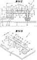
In
Jeweils längsendseitig formt der Waagebalken
In Längserstreckung des Waagebalkens
Die Kerbungen
Zufolge der Anordnung der Kerbungen
Die beiden Zonen geringster Balkenstärke sind in Längserstreckung des Waagebalkens
Der so gestaltete Waagebalken
Der Waagebalken
Das Plattenteil
Weiter ist das Plattenteil
Das Plattenteil
In vertikaler Überdeckung zu einem Befestigungsbereich
Der Befestigungsbereich
Auch der gegenüberliegende Befestigungsbereich
Das Einwirkungsteil
Die vorbeschriebenen Bohrungen sind durchsetzt von einer weiteren Befestigung
Zufolge der Verschraubung mittels der Befestigungsschrauben
Zur Messung der Zug- und Druckspannungen auf der Balkenoberseite ist auf dieser Oberseite
Der Dehnungsmessstreifen
Eine zusätzliche Belastung des Chassis
Zufolge der vollflächigen Anlage des Plattenteils
In
Alle offenbarten Merkmale sind (für sich) erfindungswesentlich. In die Offenbarung der Anmeldung wird hiermit auch der Offenbarungsinhalt der zugehörigen/beigefügten Prioritätsunterlagen (Abschrift der Voranmeldung) vollinhaltlich mit einbezogen, auch zu dem Zweck, Merkmale dieser Unterlagen in Ansprüche vorliegender Anmeldung mit aufzunehmen. Die Unteransprüche charakterisieren in ihrer fakultativ nebengeordneten Fassung eigenständige erfinderische Weiterbildung des Standes der Technik, insbesondere um auf Basis dieser Ansprüche Teilanmeldungen vorzunehmen.All disclosed features are essential to the invention. The disclosure of the associated / attached priority documents (copy of the prior application) is hereby also incorporated in full in the disclosure of the application, also for the purpose of including features of these documents in claims of the present application. The subclaims characterize in their optional sibling version independent inventive development of the prior art, in particular to make on the basis of these claims divisional applications.
BezugszeichenlisteLIST OF REFERENCE NUMBERS
- 11
- Küchenmaschinefood processor
- 22
- Gehäusecasing
- 33
- Wägezelleload cell
- 44
- Rührgefäßmixing vessel
- 55
- Aufnahmeadmission
- 66
- Rührwerkagitator
- 77
- Schalterswitch
- 88th
- Chassischassis
- 99
- Gehäusebodencaseback
- 1010
- Displaydisplay
- 1111
- Waagebalkenbalance beam
- 1212
- Befestigungsbereichfastening area
- 1313
- Befestigungsbereichfastening area
- 1414
- Kerbungnotching
- 1515
- Kerbungnotching
- 1616
- BreitseitenflächeBroadside surface
- 1717
- BreitseitenflächeBroadside surface
- 1818
- Oberseitetop
- 1919
- Unterseitebottom
- 2020
- KerbungsrandkanteKerbungsrandkante
- 2121
- KerbungsrandkanteKerbungsrandkante
- 2222
- Plattenteilplate part
- 2323
- Sockelteilbase part
- 2424
- Vertikalbohrungvertical drilling
- 2525
- DurchgangsbohrungThrough Hole
- 2626
- DurchgangsbohrungThrough Hole
- 2727
- Befestigungsschraubefixing screw
- 2828
- Gewindebohrungthreaded hole
- 2929
- Schraubenkopfscrew head
- 3030
- Vertikalbohrungvertical drilling
- 3131
- DurchgangsbohrungThrough Hole
- 3232
- Einwirkungsteilexposure part
- 3333
- DurchgangsbohrungThrough Hole
- 3434
- Befestigungsschraubefixing screw
- 3535
- Schraubenkopfscrew head
- 3636
- Fußteilfootboard
- 3737
- DehnungsmessstreifenStrain gauges
- aa
- Balkenstärkebeam thickness
- a'a '
- Balkenstärkebeam thickness
- bb
- Breitewidth
- b'b '
- Breitewidth
- cc
- Höheheight
- c'c '
- Dickethickness
- ll
- Längelength
- K1 K 1
- Kerbstellenotch place
- K2 K 2
- Kerbstellenotch place
Claims (10)
Priority Applications (1)
| Application Number | Priority Date | Filing Date | Title |
|---|---|---|---|
| DE102009059242A DE102009059242A1 (en) | 2009-12-21 | 2009-12-21 | Weighing cell for use in kitchen balance of food processor utilized for preparing food, has plate part attached to scale beams at notch side and provided with constant thickness over length between fastening areas |
Applications Claiming Priority (1)
| Application Number | Priority Date | Filing Date | Title |
|---|---|---|---|
| DE102009059242A DE102009059242A1 (en) | 2009-12-21 | 2009-12-21 | Weighing cell for use in kitchen balance of food processor utilized for preparing food, has plate part attached to scale beams at notch side and provided with constant thickness over length between fastening areas |
Publications (1)
| Publication Number | Publication Date |
|---|---|
| DE102009059242A1 true DE102009059242A1 (en) | 2011-06-22 |
Family
ID=44311231
Family Applications (1)
| Application Number | Title | Priority Date | Filing Date |
|---|---|---|---|
| DE102009059242A Withdrawn DE102009059242A1 (en) | 2009-12-21 | 2009-12-21 | Weighing cell for use in kitchen balance of food processor utilized for preparing food, has plate part attached to scale beams at notch side and provided with constant thickness over length between fastening areas |
Country Status (1)
| Country | Link |
|---|---|
| DE (1) | DE102009059242A1 (en) |
Cited By (6)
| Publication number | Priority date | Publication date | Assignee | Title |
|---|---|---|---|---|
| DE202011000995U1 (en) | 2011-04-28 | 2011-06-14 | Vorwerk & Co. Interholding GmbH, 42275 | Stand, especially for a table-top food processor |
| DE202012100743U1 (en) | 2012-03-02 | 2013-06-04 | Vorwerk & Co. Interholding Gmbh | Electric motor driven food processor |
| EP2600239A2 (en) | 2011-12-01 | 2013-06-05 | Vorwerk & Co. Interholding GmbH | Method for generating a display value for a weight measurement |
| EP2666397A1 (en) | 2012-05-24 | 2013-11-27 | Vorwerk & Co. Interholding GmbH | Kitchen appliance with a mixing bowl and method for installing the same |
| EP3398495A1 (en) | 2017-05-04 | 2018-11-07 | Vorwerk & Co. Interholding GmbH | Method for operating a kitchen appliance |
| DE102017114408A1 (en) | 2017-06-28 | 2019-01-03 | Vorwerk & Co. Interholding Gmbh | Kitchen appliance with a touch and pressure sensitive control panel |
-
2009
- 2009-12-21 DE DE102009059242A patent/DE102009059242A1/en not_active Withdrawn
Cited By (8)
| Publication number | Priority date | Publication date | Assignee | Title |
|---|---|---|---|---|
| DE202011000995U1 (en) | 2011-04-28 | 2011-06-14 | Vorwerk & Co. Interholding GmbH, 42275 | Stand, especially for a table-top food processor |
| EP2600239A2 (en) | 2011-12-01 | 2013-06-05 | Vorwerk & Co. Interholding GmbH | Method for generating a display value for a weight measurement |
| DE102011055932A1 (en) | 2011-12-01 | 2013-06-06 | Vorwerk & Co. Interholding Gmbh | Method for generating a display reading |
| DE202012100743U1 (en) | 2012-03-02 | 2013-06-04 | Vorwerk & Co. Interholding Gmbh | Electric motor driven food processor |
| EP2666397A1 (en) | 2012-05-24 | 2013-11-27 | Vorwerk & Co. Interholding GmbH | Kitchen appliance with a mixing bowl and method for installing the same |
| DE102012104495A1 (en) | 2012-05-24 | 2013-11-28 | Vorwerk & Co. Interholding Gmbh | Food processor with a mixing vessel and method for assembling a food processor |
| EP3398495A1 (en) | 2017-05-04 | 2018-11-07 | Vorwerk & Co. Interholding GmbH | Method for operating a kitchen appliance |
| DE102017114408A1 (en) | 2017-06-28 | 2019-01-03 | Vorwerk & Co. Interholding Gmbh | Kitchen appliance with a touch and pressure sensitive control panel |
Similar Documents
| Publication | Publication Date | Title |
|---|---|---|
| DE102009059242A1 (en) | Weighing cell for use in kitchen balance of food processor utilized for preparing food, has plate part attached to scale beams at notch side and provided with constant thickness over length between fastening areas | |
| EP2120023B1 (en) | Capsuled load cell with eccentric load calibration | |
| EP0034656B1 (en) | Platform scales and method of producing such platform scales | |
| EP0326017B1 (en) | Force measuring element for a weighing apparatus | |
| DE102008056715B4 (en) | Force plate | |
| WO2015010684A1 (en) | Rod-shaped force transducer with improved deformation behavior | |
| DE60008304T2 (en) | Shear load cell | |
| DE10224199A1 (en) | Power Load Cell | |
| DE3812860A1 (en) | RING TORSION FORCE MEASURING DEVICE | |
| EP1345015A2 (en) | Force measuring element for a weighing device and weighing device | |
| DE2341486A1 (en) | LOAD MEASURING ELEMENT | |
| CH353555A (en) | Force measuring device | |
| DE102016110577B4 (en) | Key for determining a transmitted torque | |
| EP1382562B2 (en) | Load measuring device | |
| DE2129214A1 (en) | MEASURING CONVERTER, IN PARTICULAR FOR FORCE MEASUREMENT | |
| WO2010054743A1 (en) | Top-pan electronic balance with corner load sensor system | |
| DE19838371C2 (en) | Libra | |
| DE10308803A1 (en) | Weighing scales in which the weighing cell or cells are inserted between the base and load plates to yield more compact scales with a reduced number of components | |
| DE10260577A1 (en) | Strain gauge for load cell, has resistance tracks, whose thickness can be altered e.g. by etching or abrasive techniques | |
| DE3336069A1 (en) | FORCE MEASURING LOAD CELL FOR ELECTRONIC SCALES AND THE LIKE | |
| EP1124118B1 (en) | Weighing apparatus | |
| DE3120162C2 (en) | ||
| DE10029742C2 (en) | Device for measuring force by detecting slight changes in length | |
| DE2810412C2 (en) | Electromechanical transducer with a force introduction | |
| EP1200807B1 (en) | Load-measuring device for a load-bearing element of an elevator |
Legal Events
| Date | Code | Title | Description |
|---|---|---|---|
| R119 | Application deemed withdrawn, or ip right lapsed, due to non-payment of renewal fee |