EP2665352B1 - Working apparatus for component or board - Google Patents
Working apparatus for component or board Download PDFInfo
- Publication number
- EP2665352B1 EP2665352B1 EP13001803.9A EP13001803A EP2665352B1 EP 2665352 B1 EP2665352 B1 EP 2665352B1 EP 13001803 A EP13001803 A EP 13001803A EP 2665352 B1 EP2665352 B1 EP 2665352B1
- Authority
- EP
- European Patent Office
- Prior art keywords
- displacement
- amount
- center
- rotation
- induced
- Prior art date
- Legal status (The legal status is an assumption and is not a legal conclusion. Google has not performed a legal analysis and makes no representation as to the accuracy of the status listed.)
- Active
Links
Images


Classifications
-
- G—PHYSICS
- G05—CONTROLLING; REGULATING
- G05B—CONTROL OR REGULATING SYSTEMS IN GENERAL; FUNCTIONAL ELEMENTS OF SUCH SYSTEMS; MONITORING OR TESTING ARRANGEMENTS FOR SUCH SYSTEMS OR ELEMENTS
- G05B13/00—Adaptive control systems, i.e. systems automatically adjusting themselves to have a performance which is optimum according to some preassigned criterion
- G05B13/02—Adaptive control systems, i.e. systems automatically adjusting themselves to have a performance which is optimum according to some preassigned criterion electric
- G05B13/0205—Adaptive control systems, i.e. systems automatically adjusting themselves to have a performance which is optimum according to some preassigned criterion electric not using a model or a simulator of the controlled system
- G05B13/021—Adaptive control systems, i.e. systems automatically adjusting themselves to have a performance which is optimum according to some preassigned criterion electric not using a model or a simulator of the controlled system in which a variable is automatically adjusted to optimise the performance
-
- B—PERFORMING OPERATIONS; TRANSPORTING
- B25—HAND TOOLS; PORTABLE POWER-DRIVEN TOOLS; MANIPULATORS
- B25J—MANIPULATORS; CHAMBERS PROVIDED WITH MANIPULATION DEVICES
- B25J9/00—Programme-controlled manipulators
- B25J9/16—Programme controls
-
- H—ELECTRICITY
- H05—ELECTRIC TECHNIQUES NOT OTHERWISE PROVIDED FOR
- H05K—PRINTED CIRCUITS; CASINGS OR CONSTRUCTIONAL DETAILS OF ELECTRIC APPARATUS; MANUFACTURE OF ASSEMBLAGES OF ELECTRICAL COMPONENTS
- H05K13/00—Apparatus or processes specially adapted for manufacturing or adjusting assemblages of electric components
- H05K13/04—Mounting of components, e.g. of leadless components
- H05K13/0404—Pick-and-place heads or apparatus, e.g. with jaws
- H05K13/0408—Incorporating a pick-up tool
- H05K13/041—Incorporating a pick-up tool having multiple pick-up tools
-
- H—ELECTRICITY
- H05—ELECTRIC TECHNIQUES NOT OTHERWISE PROVIDED FOR
- H05K—PRINTED CIRCUITS; CASINGS OR CONSTRUCTIONAL DETAILS OF ELECTRIC APPARATUS; MANUFACTURE OF ASSEMBLAGES OF ELECTRICAL COMPONENTS
- H05K13/00—Apparatus or processes specially adapted for manufacturing or adjusting assemblages of electric components
- H05K13/08—Monitoring manufacture of assemblages
- H05K13/081—Integration of optical monitoring devices in assembly lines; Processes using optical monitoring devices specially adapted for controlling devices or machines in assembly lines
- H05K13/0812—Integration of optical monitoring devices in assembly lines; Processes using optical monitoring devices specially adapted for controlling devices or machines in assembly lines the monitoring devices being integrated in the mounting machine, e.g. for monitoring components, leads, component placement
-
- H—ELECTRICITY
- H05—ELECTRIC TECHNIQUES NOT OTHERWISE PROVIDED FOR
- H05K—PRINTED CIRCUITS; CASINGS OR CONSTRUCTIONAL DETAILS OF ELECTRIC APPARATUS; MANUFACTURE OF ASSEMBLAGES OF ELECTRICAL COMPONENTS
- H05K13/00—Apparatus or processes specially adapted for manufacturing or adjusting assemblages of electric components
- H05K13/08—Monitoring manufacture of assemblages
- H05K13/089—Calibration, teaching or correction of mechanical systems, e.g. of the mounting head
Definitions
- the present invention relates to a working apparatus for a component or a board, and more particularly, it relates to a working apparatus for a component or a board including a head unit with imaging portions.
- a component mounting apparatus or the like including a head unit with imaging portions is known in general, as disclosed in Japanese Patent Laying-Open No. 2005-347555 , for example.
- Japanese Patent Laying-Open No. 2005-347555 discloses a component mounting apparatus including a component placing head with two cameras (imaging portions) and component suction nozzles (working mechanism portions) arranged between these cameras, capable of being moved to an arbitrary position on a board.
- the component suction nozzles between the cameras are arranged on a straight line (X-axis) passing through the centers of the two cameras, and the rotation angle (yawing value) of the component placing head with respect to the X-axis in the plane (X-Y plane) of the board can be grasped with the two cameras.
- the amounts of displacement (displacement in a direction Y) of the component suction nozzles from the X-axis are obtained on the basis of horizontal distances from the centers of the cameras to the component suction nozzles and the rotation angle of the component placing head.
- the component suction nozzles are arranged on the straight line (X-axis) passing through the centers of the two cameras, so that the amounts of displacement (displacement in the direction Y) of the component suction nozzles are easily grasped on the basis of center-to-center distances between the cameras and the component suction nozzles and the rotation angle of the component placing head.
- the component suction nozzles are arranged at positions displaced from the straight line passing through the centers of the two cameras, for example, it is difficult to grasp the amounts of displacement of the component suction nozzles by directly applying the aforementioned method.
- the component suction nozzles (working mechanism portions) cannot be accurately moved to the component mounting positions (working positions) in the case of the component placing head in which the component suction nozzles (working mechanism portions) are not arranged on the straight line passing through the centers of the imaging portions.
- JP 2001 244696 A discloses an apparatus to mount a component on a substrate.
- the apparatus comprises a main control means for performing a preliminary operation wherein, with a dummy substrate bearing plural marks positioned at a working position, a head unit is moved and a substrate recognizing camera mounted on the head unit images each mark.
- the apparatus further comprises a calculation means wherein a deviation between a mark position with the substrate recognizing camera and a theoretical position for the mark is acquired and a correction amount for the mounting position of the part by the head unit is acquired on the basis of the deviation.
- the apparatus further comprises a storage means where the correction amount acquired by the calculation means is stored.
- the main control means controls, at normal mounting operation, the driving of the head unit based on the correction amount stored in the storage means.
- US 2009/252400 A1 discloses a method in order to recognize grid-like reference marks on a jig plate positioned in a mounting area by means of a substrate recognizing camera respectively, to obtain a positional shift amount of a mounting head with respect to XY coordinates on an apparatus of each of the reference marks, and to correct a mounting position, thereby carrying out a mounting operation.
- a jig component positioned and mounted sequentially on each of the reference marks formed on the jig plate by means of a nozzle head is recognized by the substrate recognizing camera, a shift amount of XY coordinates acquired by the camera recognition of the jig component from XY coordinates on the apparatus of the corresponding reference mark is obtained as corrected data on the nozzle head with respect to the reference mark, and a correction is carried out based on the corrected data when an electronic component is to be mounted on a substrate by means of the nozzle head.
- DE 102 24 993 C1 discloses a surface positioning device distortion measuring method.
- the measuring method uses the positioning device for relative movement between a camera and an assembly field, with detection of two sets of perpendicular reference markings by the camera and identification of corresponding measuring positions for calculation of the local distortion from the vectorial distance of each measuring position from each reference position.
- the present invention has been proposed in order to solve the aforementioned problem, and an object of the present invention is to provide a working apparatus for a component or a board and a component mounting apparatus each capable of accurately moving a working mechanism portion to a working position even if the working mechanism portion is not arranged on a straight line passing through the centers of imaging portions.
- a working apparatus for a component or a board includes a head unit including a first imaging portion, a second imaging portion, and a working mechanism portion arranged at a position other than on a straight line passing through the center of the first imaging portion and the center of the second imaging portion in a plan view and a control portion performing control of moving the head unit in a horizontal plane, while the control portion is configured to perform control of calculating a rotation angle in the horizontal plane of the head unit from displacement of the center of the first imaging portion and displacement of the center of the second imaging portion and correcting the center position of the working mechanism portion on the basis of the amount of rotation-induced displacement of the center of the working mechanism portion due to the rotation angle, a first amount of displacement in a first direction in the horizontal plane being not induced by rotation of the center of the working mechanism portion, and a second amount of displacement in a second direction orthogonal to the first direction in the horizontal plane being not induced by the rotation of the center of the working mechanism portion
- the control portion is configured to perform control of calculating the rotation angle in the horizontal plane of the head unit from the displacement of the center of the first imaging portion and the displacement of the center of the second imaging portion and correcting the center position of the working mechanism portion on the basis of the amount of rotation-induced displacement of the center of the working mechanism portion due to the rotation angle, the first amount of displacement in the first direction in the horizontal plane being not induced by the rotation of the center of the working mechanism portion, and the second amount of displacement in the second direction orthogonal to the first direction in the horizontal plane being not induced by the rotation of the center of the working mechanism portion when moving the head unit, whereby the control portion can properly correct the center position of the working mechanism portion with the rotation angle of the head unit, the first amount of displacement in the first direction being not induced by the rotation, and the second amount of displacement in the second direction being not induced by the rotation when moving the head unit even if the head unit in which the working mechanism portion
- control portion is preferably configured to perform control of correcting the center position of the working mechanism portion and moving the head unit on the basis of the rotation angle in the horizontal plane of the head unit, the amount of rotation-induced displacement, the first amount of displacement being not induced by the rotation of the center of the working mechanism portion, and the second amount of displacement being not induced by the rotation of the center of the working mechanism portion, when an operation on the component or the board is performed with the head unit.
- the control portion it is only necessary for the control portion to calculate the correction amount of the center position of the working mechanism portion each time the operation on the component or the board is performed.
- control portion performs control of correcting the center position of the working mechanism portion and moving the head unit when the operation on the component or the board is performed
- the control portion is preferably configured to perform control of correcting the center position of the working mechanism portion and moving the head unit on the basis of the rotation angle in the horizontal plane of the head unit, the amount of rotation-induced displacement, the first amount of displacement being not induced by the rotation of the center of the working mechanism portion, and the second amount of displacement being not induced by the rotation of the center of the working mechanism portion, each time a single operation on the individual component or the individual board is performed.
- the control of correcting the center position of the working mechanism portion and moving the head unit is performed once in every operation on the individual component or the individual board, and hence the working mechanism portion can be accurately moved to the corresponding working position each time an operation is performed on each component or each board at a different working position.
- control portion performs control of correcting the center position of the working mechanism portion and moving the head unit when the operation on the component or the board is performed
- control portion is preferably configured to perform arithmetic processing for correcting the center position of the working mechanism portion and perform control of moving the head unit on the basis of the rotation angle in the horizontal plane of the head unit, the amount of rotation-induced displacement, the first amount of displacement being not induced by the rotation of the center of the working mechanism portion, and the second amount of displacement being not induced by the rotation of the center of the working mechanism portion.
- the head unit can be moved actually while the arithmetic processing for correcting the center position of the working mechanism portion is performed, and hence the takt time required for the operation on the component or the board can be inhibited from increasing due to the arithmetic processing.
- the amount of rotation-induced displacement preferably includes the first amount of rotation-induced displacement in the first direction of the center position of the working mechanism portion based on the rotation angle and distances in the first and second directions from the center position of the working mechanism portion to the center position of the first imaging portion or the second imaging portion and the second amount of rotation-induced displacement in the second direction of the center position of the working mechanism portion based on the rotation angle and the distances in the first and second directions from the center position of the working mechanism portion to the center position of the first imaging portion or the second imaging portion
- the control portion is preferably configured to perform control of correcting the center position of the working mechanism portion on the basis of the first correction amount in the first direction of the center position of the working mechanism portion based on the first amount of rotation-induced displacement and the first amount of displacement and the second correction amount in the second direction of the center position of the working mechanism portion based on the second amount of rotation-induced displacement and the second amount of displacement.
- the first amount of rotation-induced displacement and the second amount of rotation-induced displacement can be easily grasped on the basis of the positional relation between the center position of the working mechanism portion and the center position of the first imaging portion or the second imaging portion in the head unit, and the first correction amount in the first direction and the second correction amount in the second direction of the center position of the working mechanism portion in the head unit in motion can be accurately obtained on the basis of the first and second amounts of rotation-induced displacement induced by this rotational movement and the first and second amounts of displacement being not induced by the rotation of the center of the working mechanism portion.
- the first correction amount is preferably a sum of the first amount of rotation-induced displacement and the first amount of displacement
- the second correction amount is preferably a sum of the second amount of rotation-induced displacement and the second amount of displacement. According to this structure, the control portion can easily calculate the correction amount (first correction amount) in the first direction and the correction amount (second correction amount) in the second direction of the center position of the working mechanism portion.
- the control portion is preferably configured to perform control of moving the center position of the working mechanism portion to position coordinates obtained by subtracting the first correction amount in the first direction and the second correction amount in the second direction from the theoretical position coordinates of the center position of the working mechanism portion, respectively, when moving the head unit.
- the center position of the working mechanism portion can be easily corrected with the first and second correction amounts in the arithmetic processing performed by the control portion, and hence the working mechanism portion of the head unit can be easily moved to a working position after correction.
- the aforementioned working apparatus for a component or a board preferably further includes a correction table to which the control portion refers for the amount of displacement of the actual position coordinates of the center of the first imaging portion with respect to the theoretical position coordinates of the center of the first imaging portion and the amount of displacement of the actual position coordinates of the center of the second imaging portion with respect to the theoretical position coordinates of the center of the second imaging portion when moving the head unit in the horizontal plane, and.the control portion is preferably configured to perform control of calculating the rotation angle in the horizontal plane of the head unit from the displacement of the center of the first imaging portion and the displacement of the center of the second imaging portion grasped on the basis of the correction table and correcting the center position of the working mechanism portion on the basis of the amount of rotation-induced displacement of the center of the working mechanism portion due to the rotation angle, the first amount of displacement being not induced by the rotation of the center of the working mechanism portion, and the second amount of displacement being not induced by the rotation of the center of the working mechanism portion when moving the head unit.
- the arithmetic processing for correcting the center position of the working mechanism portion can be promptly performed on the basis of the rotation angle in the horizontal plane of the head unit, the amount of rotation-induced displacement, and the first and second amounts of displacement being not induced by the rotation of the center of the working mechanism portion, effectively utilizing the correction table.
- the correction table preferably includes a first correction table in which the amount of displacement of the actual position coordinates of the center of the first imaging portion with respect to the theoretical position coordinates of the center of the first imaging portion is defined and a second correction table in which the amount of displacement of the actual position coordinates of the center of the second imaging portion with respect to the theoretical position coordinates of the center of the second imaging portion is defined, and the amount of rotation-induced displacement is preferably calculated with the first correction table and the second correction table while the first amount of displacement and the second amount of displacement being not induced by the rotation of the center of the working mechanism portion are preferably calculated with the first correction table or the second correction table.
- the amount of rotation-induced displacement of the center of the working mechanism portion can be easily calculated with the first and second correction tables, and the first and second amounts of displacement being not induced by the rotation of the center of the working mechanism portion can be easily calculated, effectively utilizing either the first correction table or the second correction table.
- the aforementioned working apparatus for a component or a board according to the aspect further includes a moving mechanism portion so configured that the head unit is movable in the horizontal plane, and the control portion is configured to perform control of calculating the rotation angle in the horizontal plane of the head unit from the displacement of the center of the first imaging portion and the displacement of the center of the second imaging portion resulting from distortion of the moving mechanism portion and correcting the center position of the working mechanism portion on the basis of the amount of rotation-induced displacement of the center of the working mechanism portion due to the rotation angle, the first amount of displacement being not induced by the rotation of the center of the working mechanism portion, and the second amount of displacement being not induced by the rotation of the center of the working mechanism portion when moving the head unit by the moving mechanism portion.
- the center position of the working mechanism portion can be properly corrected with the amount of rotation-induced displacement of the center of the working mechanism portion resulting from rotation of the head unit due to the distortion of the moving mechanism portion and the first and second amounts of displacement being not induced by the rotation when the head unit is moved.
- the moving mechanism portion preferably includes a rail member extending in the first direction to move the head unit along the first direction
- the control portion is preferably configured to perform control of calculating the rotation angle in the horizontal plane of the head unit from the displacement of the center of the first imaging portion and the displacement of the center of the second imaging portion resulting from deformation of the rail member in the second direction and correcting the center position of the working mechanism portion on the basis of the amount of rotation-induced displacement of the center of the working mechanism portion due to the rotation angle, the first amount of displacement being not induced by the rotation of the center of the working mechanism portion, and the second amount of displacement being not induced by the rotation of the center of the working mechanism portion when moving the head unit.
- the center position of the working mechanism portion can be properly corrected with the amount of rotation-induced displacement of the center of the working mechanism portion resulting from the rotation of the head unit moving on the rail member due to the deformation of the rail member and the first and second amounts of displacement being not induced by the rotation when the head unit is moved.
- a plurality of working mechanism portions are preferably provided on the head unit, and the control portion is preferably configured to perform control of calculating the rotation angle in the horizontal plane of the head unit from the displacement of the center of the first imaging portion and the displacement of the center of the second imaging portion for each of the plurality of working mechanism portions and individually correcting each of the center positions of the working mechanism portions on the basis of the amount of rotation-induced displacement of each of the centers of the working mechanism portions due to the rotation angle, the first amount of displacement being not induced by the rotation of each of the centers of the working mechanism portions, and the second amount of displacement being not induced by the rotation of each of the centers of the working mechanism portions when moving the head unit.
- the control portion performs control of correcting the respective center positions of the working mechanism portions and moving the head unit, so that the working mechanism portions corresponding to the respective working positions can be accurately moved with respect to all operations performed with this head unit.
- the head unit is preferably configured to be movable along the first direction
- the first imaging portion and the second imaging portion are preferably arranged at positions aligned in the first direction
- the first amount of displacement and the second amount of displacement of the working mechanism portion each preferably include a first component based on displacement of the center position of the first imaging portion or the second imaging portion from the theoretical position coordinates of the center position of the first imaging portion or the second imaging portion
- the control portion is preferably configured to perform control of correcting the center position of the working mechanism portion on the basis of the amount of rotation-induced displacement of the center of the working mechanism portion, the rotation angle in the horizontal plane of the head unit, the first amount of displacement including the first component, being not induced by the rotation, and the second amount of displacement including the first component, being not induced by the rotation.
- control portion can properly correct the center position of the working mechanism portion when moving the head unit in which the first imaging portion and the second imaging portion are aligned in the first direction. Consequently, the working mechanism portion can be accurately moved to the working position for the component or the board.
- the head unit is preferably configured to be movable along the first direction
- the second imaging portion is preferably arranged at a different position in the second direction with respect to the first imaging portion
- the first amount of displacement and the second amount of displacement of the working mechanism portion each preferably include a second component based on positional displacement of the second imaging portion along the second direction with respect to the first imaging portion in addition to the first component based on the displacement of the center position of the first imaging portion or the second imaging portion from the theoretical position coordinates of the center position of the first imaging portion or the second imaging portion
- the control portion is preferably configured to perform control of correcting the center position of the working mechanism portion on the basis of the amount of rotation-induced displacement of the center of the working mechanism portion, the rotation angle in the horizontal plane of the head unit, the first amount of displacement including the first and second components, being not induced by the rotation, and the second amount of displacement including the first and second components, being not induced by the rotation.
- control portion can properly correct the center position of the working mechanism portion by taking the second component based on the positional displacement in the second direction into consideration when moving the head unit even if the head unit in which the second imaging portion is arranged at the different position in the second direction with respect to the first imaging portion is used. Consequently, the working mechanism portion can be accurately moved to the working position for the component or the board.
- the head unit preferably further includes a slide guide portion provided to be movable along the first direction and guiding movement of the head unit in the first direction, the center position of the slide guide portion rotationally displaced along with rotation of the center position of the first imaging portion or the second imaging portion is preferably grasped on the basis of the rotation angle and the positional relation between the slide guide portion and the first imaging portion or the second imaging portion, the amount of rotation-induced displacement is preferably calculated on the basis of the rotation angle and the positional relation between the grasped center position of the slide guide portion and the center position of the working mechanism portion, and the control portion is preferably configured to perform control of correcting the center position of the working mechanism portion on the basis of the amount of rotation-induced displacement, the first amount of displacement being not induced by the rotation, and the second amount of displacement being not induced by the rotation.
- the center position of the working mechanism portion based on the displacement of the center position of the first imaging portion or the second imaging portion can be corrected also by taking the positional information regarding the rotational displacement of the slide guide portion lying between the first imaging portion or the second imaging portion and the working mechanism portion into consideration in the arithmetic processing in addition to a case of correcting the center position of the working mechanism portion on the basis of only the relation between the center position of the first imaging portion or the second imaging portion and the center position of the working mechanism portion.
- the center position regarding the rotational displacement of the slide guide portion actually moving the head unit on the basis of the rotation angle is first grasped (predicted), and then the amount of rotation-induced displacement of the center position of the working mechanism portion induced by the grasped rotational displacement of the center position of the slide guide portion is calculated, whereby the final correction amount of the center position of the working mechanism portion can be calculated.
- the working mechanism portion can be accurately moved to the working position also by the aforementioned method.
- the surface mounter 100 is an example of the "working apparatus for a component or a board" or the “component mounting apparatus" in the present invention.
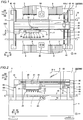
- the surface mounter 100 is an apparatus for mounting electronic components 2 on a printed board (wiring board) 1, as shown in Figs. 1 and 2 .
- the surface mounter 100 includes a base 4, a board conveying portion 10 provided on the base 4 (front side in the plane of the figure), a head unit 20 movable along an X-Y plane (plane of the figure) above the board conveying portion 10, a support portion 30 supporting the head unit 20 to be movable in a direction X, and a moving mechanism 40 moving the support portion 30 in a direction Y, as shown in Fig. 1 .
- the electronic components 2 are examples of the "component” in the present invention.
- the directions X and Y are examples of the "first direction” and the "second direction” in the present invention, respectively.
- a plurality of rows of tape feeders 3 to supply the electronic components 2 are arranged on both sides (Y1 and Y2 sides) of the board conveying portion 10.
- the tape feeders 3 hold reels (not shown) on which tapes holding a plurality of electronic components 2 at prescribed intervals are wound. The reels are rotated to send out the tapes, whereby the electronic components 2 are supplied from forward end portions of the tape feeders 3.
- the head unit 20 acquires the electronic components 2 from the tape feeders 3, and has a function of mounting the electronic components 2 on the printed board 1 placed on the board conveying portion 10.
- the electronic components 2 are small pieces of electronic components such as ICs, transistors, capacitors, and resistors.
- a cover 6 is attached to a casing 7 provided on the base 4, as shown in Fig. 2 .
- the cover 6 is configured to pivot upward (along arrow U) relative to the casing 7, and is so configured that a user (operator) can access the board conveying portion 10.
- Fig. 2 the internal structure that is covered with the casing 7 and unseen from the outside under normal circumstances is also shown by solid lines for convenience of illustration.
- a controller 70 to perform operational control of each portion of a mounter body is built in the surface mounter 100.
- the controller 70 is mainly constituted by a central processing unit (CPU) 71, a storage portion 72 (an operating program storage portion 72a and a correction data storage portion 72b), an image processing portion 73, a motor control portion 74, and an external input/output portion 75. Components constituting the controller 70 are later described in detail.
- the central processing unit 71 is an example of the "control portion" in the present invention.
- the board conveying portion 10 includes a pair of conveyor portions 11 extending in the direction X that is the conveying direction of the printed board 1, as shown in Fig. 1 .
- the conveyor portions 11 are provided with a plurality of board sensors (not shown) detecting the conveying condition of the printed board 1.
- the printed board 1 held by the conveyor portions 11 is conveyed on the basis of the detection results of the board sensors.
- the board conveying portion 10 is internally provided with a clamp mechanism holding the printed board 1 being conveyed while stopping the printed board 1 at a stop position during mounting of the components.
- the support portion 30 has a ball screw shaft 31 extending in the direction X, a servomotor 32 rotating the ball screw shaft 31, and a guide rail 33 extending along the ball screw shaft 31, as shown in Fig. 2 .
- the head unit 20 has a slide guide portion 21 attached with a ball nut (not shown) receiving the ball screw shaft 31. Thus, the head unit 20 is moved back and forth along the direction X following the rotation of the ball screw shaft 31 while the slide guide portion 21 is guided by the guide rail 33.
- the support portion 30 is an example of the "moving mechanism portion” in the present invention
- the guide rail 33 is an example of the "rail member" in the present invention.
- the support portion 30 is configured to be movable in the direction Y orthogonal to the direction X in a state where the same is placed on the moving mechanism 40 fixed onto the base 4.
- the moving mechanism 40 has a ball screw shaft 41 extending in the direction Y, a servomotor 42 rotating the ball screw shaft 41, and a pair of guide rails 43 extending along the ball screw shaft 41, as shown in Fig. 1 .
- the guide rails 43 movably support both end portions (in the direction X) of the support portion 30.
- the support portion 30 is provided with a ball nut 35 receiving the ball screw shaft 41.
- the head unit 20 is configured to be capable of moving to an arbitrary position along the X-Y plane over the base 4 by rotating the ball screw shafts 31 and 41.
- the head unit 20 has a mounting head 22 fixed to the slide guide portion 21 and a main camera 23 and an auxiliary camera 24 respectively attached to both end portions (in the direction X) of the mounting head 22, as shown in Fig. 2 .
- the distance of the main camera 23 from the ball screw shaft 31 (X-axis) and the distance of the auxiliary camera 24 from the ball screw shaft 31 are substantially equal to each other.
- a straight line (X-axis) 500 passing through the centers of the main camera 23 and the auxiliary camera 24 and the ball screw shaft 31 are substantially parallel to each other, as shown in Fig. 1 .
- the mounting head 22 has a plurality of (six) suction nozzles 25 provided on the lower surface side (Z1 side in Fig. 2 ) opposed to the printed board 1.
- each of the suction nozzles 25 is arranged at a position offset by a distance L3 along arrow Y1 from the straight line 500.
- each of the suction nozzles 25 has a function of holding an electronic component 2 by suctioning the electronic component 2 with negative pressure generated in a forward end portion of the nozzle by a negative pressure generator (not shown).
- the main camera 23 and the auxiliary camera 24 are examples of the "first imaging portion” and the “second imaging portion” in the present invention, respectively.
- the suction nozzles 25 are examples of the "working mechanism portion" in the present invention.
- the shape of the guide rail 33 is slightly distorted.
- the guide rail 33 is not completely straight along the direction X, but has undulation as a whole with small displacement in the direction Y.
- the slide guide portion 21 and the head unit 20 move while slightly swaying from side to side with respect to the X-axis in a horizontal plane (X-Y plane) due to the undulation of the sliding surface.
- the head unit 20 is moved to a mounting position on the printed board 1 (see Fig. 1 ), as shown in Fig. 4 .
- the head unit 20 is parallel moved by a prescribed amount along arrow Y1 due to the undulation of the sliding surface and further rotated slightly counterclockwise by a horizontal rotation angle ⁇ from the displaced position.
- the magnitude of the horizontal rotation angle ⁇ is illustrated in an exaggerated manner for convenience, and actually, the posture of the head unit 20 is not changed so much.
- the periphery of the head unit 20 is schematically shown in a state where the surface mounter 100 shown in Fig. 1 is turned upside down in an anteroposterior direction (direction Y) for convenience of description.
- the following drive control is applied to the head unit 20 in which the center positions of the suction nozzles 25 are displaced by the distance L3 along arrow Y1 from the straight line 500 passing through the center position of the main camera 23 and the center position of the auxiliary camera 24.
- the central processing unit 71 adjusts the numbers of rotations of the servomotors 32 and 42 (see Fig. 3 ) while taking the previously grasped distortion (undulation) of the guide rail 33 into consideration and performs control of moving the head unit 20.
- This drive control is performed for each mounting operation on each of the electronic components 2 (see Fig. 2 ).
- a suction nozzle 25 suctioning the electronic component 2 can be accurately moved to a prescribed mounting position of the printed board 1 each time. Operations performed by the central processing unit 71 in order to perform this drive control are hereinafter described in detail.
- Arithmetic processing performed to mount one electronic component 2 is summarized below.
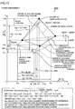
- the amount of movement Mv(dx) in the direction X of the center position of the suction nozzle 25 and the amount of movement Mv(dy) in the direction Y of the center position of the suction nozzle 25 are calculated on the basis of the horizontal rotation angle ⁇ of the head unit 20 (see Fig. 4 ) in the X-Y plane and the amount of X-direction displacement Xdx of the suction nozzle 25 and the amount of Y-direction displacement Xdy of the suction nozzle 25 (see Fig. 4 ) induced by the displacement of the center position of the main camera 23 from the theoretical center position thereof, as shown in Fig. 5 .
- the horizontal rotation angle ⁇ is an example of the "rotation angle in the horizontal plane” in the present invention.
- the amounts of movement Mv(dx) and Mv(dy) are examples of the "first correction amount” and the "second correction amount” in the present invention, respectively.
- the amount of X-direction displacement Xdx and the amount of Y-direction displacement Xdy are examples of the "first amount of displacement” and the “second amount of displacement” in the present invention, respectively.
- a method for obtaining parameters used in the arithmetic processing is hereinafter described.
- the straight line 500 in the head unit 20 and the theoretical X-axis line 600 (see Fig. 4 ) of the mounter are substantially parallel to each other no matter to which position the head unit 20 is moved, as shown in Fig. 5 .
- the center position coordinates of the main camera 23 that are a theoretical position are represented by (Xm, Ym)
- the center position coordinates of the auxiliary camera 24 that are a theoretical position are represented by (Xs, Ym).
- the center position coordinates of the suction nozzle 25 that are a theoretical position spaced by the distance L3 from the straight line 500 are represented by (Xu1, Yu1)
- the posture of the head unit 20 is expressed by a figure G1 (drawn with broken lines) passing through the center positions of the main camera 23, the auxiliary camera 24, and the suction nozzle 25.
- the head unit 20 when the head unit 20 is moved to reach a certain position in a state where the guide rail 33 has distortion (undulation) actually as shown in Fig. 4 , the straight line 500 in the head unit 20 and the X-axis line 600 of the mounter intersect with each other at the horizontal rotation angle ⁇ .
- the head unit 20 reaches the position of a figure G2 (drawn with solid lines) by moving obliquely parallel along arrow X1 and arrow Y1 from the position of the figure G1 and further rotating counterclockwise by the horizontal rotation angle ⁇ with respect to the main camera 23 in Fig. 5 . Therefore, the center position coordinates of the suction nozzle 25 are rotationally moved from theoretical position coordinates (Xu1, Yu1) in the figure G1 to actual position coordinates (Xu2, Yu2) in the figure G2.
- the amount of X-direction displacement Xdx in the expression 1 is a value calculated as the amount of X-direction displacement of the suction nozzle 25 at a position corresponding to the X-coordinate (Xu1) of the suction nozzle 25 in a correction table 5a (see Fig. 7 ), described later, acquired regarding the main camera 23.
- the amount of Y-direction displacement Xdy in the expression 2 is a value calculated as the amount of Y-direction displacement of the suction nozzle 25 at a position corresponding to the Y-coordinate (Yu1) of the suction nozzle 25 in the correction table 5a acquired regarding the main camera 23.
- Udx and Udy are values calculated as the amount of rotation-induced displacement in the direction X of the suction nozzle 25 induced by rotational movement of the horizontal rotation angle ⁇ and the amount of rotation-induced displacement in the direction Y of the suction nozzle 25 induced by the rotational movement of the horizontal rotation angle ⁇ , respectively.
- the components Ydx and Ydy are parameters corresponding to the displacement components of the suction nozzle 25 associated with the positional displacement of the auxiliary camera 24 in the direction Y with respect to the main camera 23, in the first embodiment, the main camera 23 and the auxiliary camera 24 are not positionally displaced with respect to each other in the direction Y (both lie on the straight line 500), so that both the components Ydx and Ydy are zero. Thus, the description is omitted.
- the amount of X-direction displacement Xdx consists of only the component Xdx based on the displacement of the center position of the main camera 23 from the theoretical position coordinates thereof
- the amount of Y-direction displacement Xdy consists of only the component Xdy based on the displacement of the center position of the main camera 23 from the theoretical position coordinates thereof.
- the amounts of rotation-induced displacement Udx and Udy are examples of the "first amount of rotation-induced displacement” and the "second amount of rotation-induced displacement” in the present invention, respectively.
- the components Xdx and Xdy are examples of the "first component" in the present invention.
- Xdy(M) is a value calculated as the amount of displacement along arrow Y1 of the center position coordinates of the main camera 23 from the figure G1 to the figure G2 on the basis of the correction table 5a (see Fig. 7 ) described later
- Xdy(S) is a value calculated as the amount of displacement along arrow Y1 of the center position coordinates of the auxiliary camera 24 from the figure G1 to the figure G2 on the basis of a correction table 5b (see Fig. 7 ) described later.
- the correction tables 5a and 5b are acquired by experimentally moving the head unit 20 in the mounter before the electronic components 2 (see Fig. 2 ) are mounted. This point is described later.
- the amounts of rotation-induced displacement Udx and Udy are calculated from linear transformation formulae for coordinates in relation to rotational movement.
- the amount of rotation-induced displacement Udx in the direction X of the center position of the suction nozzle 25 is calculated on the basis of the horizontal rotation angle ⁇ , the relative position Xuo of the center position of the suction nozzle 25 in the direction X with respect to the center position of the main camera 23, and the relative position Yuo of the center position of the suction nozzle 25 in the direction Y with respect to the center position of the main camera 23.
- the amount of rotation-induced displacement Udy in the direction Y of the center position of the suction nozzle 25 is calculated on the basis of the horizontal rotation angle ⁇ , the relative position Xuo of the center position of the suction nozzle 25 in the direction X with respect to the center position of the main camera 23, and the relative position Yuo of the center position of the suction nozzle 25 in the direction Y with respect to the center position of the main camera 23.
- the central processing unit 71 derives the amounts of rotation-induced displacement Udx and Udy of the suction nozzle 25 on the basis of the machine coordinates of the main camera 23, the auxiliary camera 24, and the suction nozzle 25 (the center position coordinates (Xm, Ym) of the main camera 23, the center position coordinates (Xs, Ym) of the auxiliary camera 24, and the center position coordinates (Xu1, Yu1) of the suction nozzle 25) constituting the figure G1 and the result of calculation of the horizontal rotation angle ⁇ regarding movement (rotational movement) from the figure G1 to the figure G2 acquired with the main camera 23 and the auxiliary camera 24, and estimates the amounts of movement Mv(dx) and Mv(dy) of the center position of the suction nozzle 25 moved to an arbitrary position as in the figure G2, further using the amount of X-direction displacement Xdx and the amount of Y-direction displacement Xdy of the suction nozzle 25 based on the center position of the main camera 23, the auxiliary camera 24,
- this arithmetic processing is performed to perform control of correcting the number of rotations of the servomotor 32 while taking the amount of movement Mv(dx) in the direction X of the suction nozzle 25 into consideration and control of correcting the number of rotations of the servomotor 42 while taking the amount of movement Mv(dy) in the direction Y of the suction nozzle 25 into consideration.
- the aforementioned control of correcting the center position (arithmetic processing for calculating the correction amounts by the central processing unit 71) is performed individually with respect to each of the six suction nozzles 25 provided on the head unit 20. Therefore, the electronic component 2 is mounted in a state where the center position of the suction nozzle 25 suctioning the electronic component 2 is corrected even if any of the six suction nozzles 25 is used to mount the electronic component 2.
- correction tables 5a and 5b data (correction tables 5a and 5b) to be used as a reference for calculating the amount of Y-direction displacement Xdy(M) of the center position of the main camera 23 and the amount of Y-direction displacement Xdy(S) of the center position of the auxiliary camera 24 used to calculate the horizontal rotation angle ⁇ , expressed in the expression 3 is previously acquired by the following measurement method.
- the correction tables 5a and 5b are examples of the "first correction table” and the "second correction table” in the present invention, respectively.
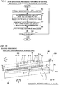
- the correction amounts (amounts of displacement) serving as reference data for correcting distortion existing in the support portion 30 (X-axis) and the moving mechanism 40 (Y-axis) of the surface mounter 100 are measured with a jig plate 105 made of glass, shown in Fig. 6 .
- a plurality of (P x Q) reference marks R R 11 to R PQ ) are printed in a lattice pattern along directions (X-axis and Y-axis directions) orthogonal to each other.
- the jig plate 105 is placed on the conveyor portions 11 and is fixed to a prescribed position. Thereafter, the head unit 20 is moved, and the individual reference marks R are successively imaged.
- the main camera 23 (see Fig. 4 ) of the head unit 20 is first used to image the individual reference marks R, and the amounts of displacement of the reference marks R imaged at respective positions from the theoretical positions are obtained.
- the support portion 30 (X-axis) and the moving mechanism 40 (Y-axis) are driven to move the center of the main camera 23 to the coordinates (1, 1) on the control program, for example.
- This calculation of the correction amounts is sequentially performed from the reference mark R 11 (actual coordinates (X 11 , Y 11 )) to a reference mark R P1 (actual coordinates (X 1P Y 1P )) along the guide rail 33 by driving the support portion 30 in the direction X.
- the calculation of the correction amounts is sequentially performed from a reference mark R 12 (actual coordinates (X 21 , Y 21 )) to a reference mark R 1Q (actual coordinates (X Q1 , Y Q1 )) along the guide rail 43 by driving the moving mechanism 40 in the direction Y while fixing the support portion 30.
- the correction amounts ( ⁇ X, ⁇ Y) are calculated with respect to each of reference marks R existing in an L-shaped area 106 surrounded by a broken line in Fig. 6 . Consequently, the correction table 5a shown in an upper region of Fig. 7 is obtained.
- the correction amounts ( ⁇ X, ⁇ Y) with respect to the auxiliary camera 24 are calculated.
- the correction amounts ( ⁇ X, ⁇ Y) are calculated with respect to each of the reference marks R 11 to R P1 and the reference marks R 12 to R 1Q while the reference marks R 11 to R P1 aligned in the direction X and the reference marks R 12 to R 10 aligned in the direction Y are successively imaged with the auxiliary camera 24. Consequently, the correction table 5b shown in a lower region of Fig. 7 is obtained.
- the correction tables 5a and 5b are stored in the correction data storage portion 72b (see Fig. 3 ) of the storage portion 72. In this manner, basic data to obtain the aforementioned amounts of Y-direction displacement Xdy(M) and Xdy(S) used to calculate the horizontal rotation angle ⁇ is previously acquired.
- the central processing unit 71 extracts the correction amounts ( ⁇ X, ⁇ Y) corresponding to a reference mark R pq nearest to the center position coordinates (Xm, Ym) of the main camera 23 while referring to the correction table 5a and extracts the correction amounts ( ⁇ X, ⁇ Y) of the auxiliary camera 24 separated by the distance Xc from the main camera 23 while referring to the correction table 5b.
- the correction amounts ( ⁇ X, ⁇ Y) only data regarding the reference marks R in the L-shaped area 106 surrounded by a broken line in Fig. 6 is stored in the correction table 5a (5b), as described above.
- the X-component ⁇ X 1p of the correction amount of a reference mark R p1 and the Y-component ⁇ Y q1 of the correction amount of a reference mark R 1q are used for the correction amounts ( ⁇ X, ⁇ Y) with respect to the reference mark R pq nearest to the center position coordinates (Xm, Ym).
- the processing is performed by substituting the components ( ⁇ X 1p , ⁇ Y q1 ) for the correction amounts ( ⁇ X, ⁇ Y) with respect to the reference mark R pq .
- the strict correction amounts ( ⁇ X, ⁇ Y) corresponding to the coordinates (Xm, Ym) are calculated by interpolating the respective correction amounts corresponding to a reference mark R (p + 1, q) next to the nearest reference mark R pq in the direction X and a reference mark R (p, q + 1) next to the nearest reference mark R pq in the direction Y, as shown in Fig. 6 .
- the central processing unit 71 obtains the amount of X-direction displacement Xdx at the position corresponding to the X-coordinate (Xu1) of the suction nozzle 25 and the amount of Y-direction displacement Xdy at the position corresponding to the Y-coordinate (Yu1) of the suction nozzle 25 on the basis of the correction table 5a. In addition, the central processing unit 71 calculates the final amount of movement Mv(dx) expressed by the expression 1 and the final amount of movement Mv(dy) expressed by the expression 2.
- the servomotor 32 see Fig.
- Each of the suction nozzles 25 is configured to be movable in the vertical direction (direction Z) with respect to the head unit 20 by a servomotor 26 (see Fig. 3 ) and an unshown elevating mechanism.
- the suction nozzles 25 suction the electronic components 2 (see Fig. 2 ) from the tape feeders 3 (see Fig. 1 ) in a state where the same are lowered to move-down positions by the head unit 20, are returned to move-up positions in a state where the same suction the electronic components 2, are conveyed to prescribed positions on the printed board 1 (see Fig. 1 ), are lowered again at the prescribed positions, and mount the electronic components 2 on the printed board 1.
- each of the suction nozzles 25 is configured to be rotated in the X-Y plane about a nozzle axis (Z-axis) by a servomotor 27 (see Fig. 3 ) and an unshown rotating mechanism.
- a servomotor 27 see Fig. 3
- an unshown rotating mechanism the postures (orientations in the X-Y plane) of the electronic components 2 held by forward end portions of the suction nozzles 25 are finely adjusted.
- a board camera 50 and a component camera 60 are fixedly set on the upper surface 4a of the base 4, a board camera 50 and a component camera 60 are fixedly set.
- the component camera 60 has a function of imaging the lower surface sides of the electronic components 2 suctioned by the suction nozzles 25 from below. Thus, whether the shapes of the electronic components 2 are good or not is determined, and whether the suction positions of the suction nozzles 25 with respect to the electronic components 2 are good or not is determined.
- the operation of the surface mounter 100 is controlled by the controller 70.
- the central processing unit 71 generally controls the operation of the surface mounter 100.
- Control programs capable of being executed by the central processing unit 71, data required to move the head unit 20, etc. are stored in the operating program storage portion 72a of the storage portion 72.
- the aforementioned correction tables 5a and 5b are stored in the correction data storage portion 72b.
- the image processing portion 73 has a function of internally generating data required for the operation of the surface mounter 100 by processing image data imaged by the main camera 23 and the auxiliary camera 24 in addition to the board camera 50.
- the motor control portion 74 is configured to control the servomotors (the servomotor 42 (see Fig. 1 ) moving the support portion 30 in the direction Y, the servomotor 32 (see Fig. 1 ) moving the head unit 20 in the direction X, the servomotor 26 moving the suction nozzles 25 in the vertical direction, the servomotor 27 rotating the suction nozzles 25 about the nozzle axes, etc.) of the surface mounter 100 on the basis of control signals output from the central processing unit 71. Furthermore, the motor control portion 74 is configured to control a servomotor of a board conveyance axis (not shown) provided in the board conveying portion 10.
- the motor control portion 74 is configured to be capable of recognizing the position of the head unit 20 in the X-Y plane, the height positions and rotation positions of the suction nozzles 25, etc. on the basis of signals from encoders (not shown) of the servomotors.
- the external input/output portion 75 has a function of controlling input/output from various operating buttons 76 including an operation start button and various sensors 77 such as the board sensors. In this manner, the surface mounter 100 is configured.
- the central processing unit 71 (see Fig. 3 ) initializes a variable (counter) for counting the number of times of imaging by the main camera 23 (see Fig. 3 ), as shown in Fig. 8 .
- the servomotor 32 (see Fig, 3 ) is driven to move the center position (center point of the imaging field of view) of the main camera 23 of the head unit 20 (see Fig. 1 ) to the theoretical coordinates (1, 1) on the control program.
- the main camera 23 images the reference mark R 11 applied to the actual coordinates (X 11 , Y 11 ) in a first row on the jig plate 105 (see Fig. 6 ) fixed to the conveyor portions 11 (see Fig. 1 ) while the center of the main camera 23 stops at the theoretical coordinates (1, 1).
- the central processing unit 71 calculates the correction amounts (amounts of displacement) of the actual coordinates (X 11 , Y 11 ) with respect to the theoretical coordinates (1, 1) as ( ⁇ X 11 , ⁇ Y 11 ) on the basis of the image processing result after imaging by the main camera 23.
- the center of the main camera 23 is moved from a theoretical coordinates (P, 1) to coordinates (1, 2), the reference mark R 12 (see Fig. 6 ) of the corresponding actual coordinates (X 21 , Y 21 ) in the first column is imaged, and the correction amounts ( ⁇ X 21 , ⁇ Y 21 ) are calculated on the basis of the image processing. Thereafter, q is incremented by one, the center of the main camera 23 is moved from the theoretical coordinates (1, 2) to coordinates (1, 3), a reference mark R 13 (see Fig.
- the central processing unit 71 prepares the correction table 5a (see Fig. 7 ) while referring to the correction amounts ( ⁇ X, ⁇ Y) corresponding to the actual coordinates stored in the working memory area of the storage portion 72, and stores the correction table 5a in the correction data storage portion 72b (see Fig. 3 ) at a step S9. In this manner, the central processing unit 71 acquires the respective correction amounts ( ⁇ X, ⁇ Y) regarding the reference marks R in the L-shaped area 106 surrounded by a broken line in Fig. 6 , and terminates this control processing.
- the aforementioned flow of this control processing is also applied to the operation of the auxiliary camera 24 (see Fig. 3 ) for obtaining the correction amounts (amounts of displacement), similarly.
- the central processing unit 71 reads the mounting position coordinates ((Xu1, Yu1), for example (see Fig. 5 )) of a first electronic component 2 (see Fig. 2 ) included in data on component mounting, as shown in Fig. 9 .
- the central processing unit 71 calculates the correction amounts (amounts of movement Mv(dx) and Mv(dy)) for moving the head unit 20 on the basis of the correction tables 5a and 5b (see Fig. 7 ).
- the central processing unit 71 performs this arithmetic processing.
- the central processing unit 71 moves the head unit 20 to the mounting position while taking the correction amounts (amounts of movement Mv(dx) and Mv(dy)) obtained at the step S22 into consideration.
- the central processing unit 71 rotates the servomotor 32 (see Fig. 3 ) while taking the amount of movement Mv(dx) in the direction X of the suction nozzle 25 into consideration and rotates the servomotor 42 (see Fig. 3 ) while taking the amount of movement Mv(dy) in the direction Y of the suction nozzle 25 into consideration.
- the central processing unit 71 mounts the electronic component 2 (see Fig. 2 ) on the printed board 1 (see Fig. 2 ) in the head unit 20 in the state moved to the mounting position.
- the central processing unit 71 determines whether or not unimplemented data on component mounting remains. If determining that the data on component mounting remains at the step S25 ("yes" determination), the central processing unit 71 returns to the step S21, and repeats the same processing described above. In other words, the central processing unit 71 reads the mounting position coordinates (Xu1, Yu1) of an electronic component 2 to be newly mounted, and calculates the correction amounts (amounts of movement Mv(dx) and Mv(dy)) regarding this electronic component 2 on the basis of the correction tables 5a and 5b (see Fig. 7 ). Then, the central processing unit 71 rotates the servomotor 32 (see Fig.
- the central processing unit 71 terminates this control processing.
- the central processing unit 71 is configured to perform control of calculating the horizontal rotation angle ⁇ of the head unit 20 in the X-Y plane from the displacement of the center of the main camera 23 and the displacement of the center of the auxiliary camera 24 and correcting the center position of the suction nozzle 25 on the basis of the amounts of rotation-induced displacement Udx and Udy of the center of the suction nozzle 25 due to the horizontal rotation angle ⁇ and the amount of X-direction displacement Xdx and the amount of Y-direction displacement Xdy in the X-Y plane that are not induced by the rotation of the center of the suction nozzle 25 when moving the head unit 20.
- the central processing unit 71 can properly correct the center position of the suction nozzle 25 with the horizontal rotation angle ⁇ of the head unit 20 and the amount of X-direction displacement Xdx and the amount of Y-direction displacement Xdy that are not induced by the rotation when moving the head unit 20 even if the head unit 20 in which the suction nozzles 25 are not arranged on the straight line 500 passing through the center of the main camera 23 and the center of the auxiliary camera 24 (the suction nozzles 25 are spaced by the distance L3 along arrow Y1 from the straight line 500) is used.
- the central processing unit 71 can accurately move the suction nozzle 25 to the mounting position on the printed board 1.
- the main camera 23 and the auxiliary camera 24 are aligned in the direction X, and the amount of X-direction displacement Xdx and the amount of Y-direction displacement Xdy of the suction nozzle 25 include only the components based on the displacement of the center position of the main camera 23 (or the auxiliary camera 24) from the theoretical position coordinates thereof.
- the central processing unit 71 is configured to perform control of correcting the center position of the suction nozzle 25 on the basis of the amounts of rotation-induced displacement Udx and Udy of the center of the suction nozzle 25, the horizontal rotation angle ⁇ of the head unit 20, and the amount of X-direction displacement Xdx and the amount of Y-direction displacement Xdy that are not induced by the rotation.
- the central processing unit 71 can properly correct the center position of the suction nozzle 25 when moving the head unit 20 in which the main camera 23 and the auxiliary camera 24 are aligned in the direction X.
- the central processing unit 71 calculates the amounts of movement Mv(dx) and Mv(dy) serving as the correction amounts of the center position of the suction nozzle 25 each time the component mounting operation is performed. Therefore, as compared with a case where correction amounts (amounts of movement Mv(dx) and Mv(dy)) regarding a large number of mounting positions are obtained in a matrix manner to cover an entire region in the X-Y plane and are stored as data in the surface mounter 100, for example, it is not necessary to hold a large amount of data, so that the amount of data held in the surface mounter 100 can be significantly reduced.
- the central processing unit 71 is configured to perform control of correcting the center position of the suction nozzle 25 and moving the head unit 20 on the basis of the horizontal rotation angle ⁇ of the head unit 20 in the X-Y plane, the amounts of rotation-induced displacement Udx and Udy, and the amount of X-direction displacement Xdx and the amount of Y-direction displacement Xdy that are not induced by the rotation of the center of the suction nozzle 25, each time a single mounting operation on each of the electronic components 2 is performed.
- the control of correcting the center position of the suction nozzle 25 and moving the head unit 20 is performed once in every operation for mounting the individual electronic components 2, and hence the suction nozzle 25 can be accurately moved to the corresponding mounting position each time a mounting operation is performed on each of the electronic components 2 at a different mounting position.
- the central processing unit 71 is configured to perform the arithmetic processing for correcting the center position of the suction nozzle 25 and perform control of moving the head unit 20 on the basis of the horizontal rotation angle ⁇ , the amounts of rotation-induced displacement Udx and Udy, and the amount of X-direction displacement Xdx and the amount of Y-direction displacement Xdy.
- the head unit 20 can be moved actually while the arithmetic processing for correcting the center position of the suction nozzle 25 is performed, and hence the takt time required for a mounting operation on each of the electronic components 2 can be inhibited from increasing due to the arithmetic processing.
- the amount of rotation-induced displacement Udx in the direction X of the center position of the suction nozzle 25 is calculated on the basis of the horizontal rotation angle ⁇ and the relative positions Xuo and Yuo of the center position of the suction nozzle 25 in the directions X and Y with respect to the center position of the main camera 23, and the amount of rotation-induced displacement Udy in the direction Y of the center position of the suction nozzle 25 is calculated on the basis of the horizontal rotation angle ⁇ and the relative positions Xuo and Yuo of the center position of the suction nozzle 25 in the directions X and Y with respect to the center position of the main camera 23.
- the central processing unit 71 is configured to perform control of correcting the center position of the suction nozzle 25 on the basis of the correction amount (amount of movement Mv(dx)) in the direction X of the center position of the suction nozzle 25 based on the amount of rotation-induced displacement Udx and the amount of X-direction displacement Xdx and the correction amount (amount of movement Mv(dy)) in the direction Y of the center position of the suction nozzle 25 based on the amount of rotation-induced displacement Udy and the amount of Y-direction displacement Xdy.
- the amounts of rotation-induced displacement Udx and Udy can be easily grasped on the basis of the positional relation between the center position of the suction nozzle 25 and the center position of the main camera 23 in the head unit 20 (the relative positions Xuo and Yuo of the suction nozzle 25 in the directions X and Y with respect to the main camera 23), and the amount of movement Mv(dx) in the direction X and the amount of movement Mv(dy) in the direction Y of the center position of the suction nozzle 25 in the head unit 20 in motion can be accurately obtained on the basis of the amounts of rotation-induced displacement Udx and Udy induced by rotational movement and the amount of X-direction displacement Xdx and the amount of Y-direction displacement Xdy that are not induced by the rotation of the center of the suction nozzle 25.
- the amount of movement Mv(dx) is obtained as a sum of the amount of rotation-induced displacement Udx and the amount of X-direction displacement Xdx, as shown in the expression 1, and the amount of movement Mv(dy) is obtained as a sum of the amount of rotation-induced displacement Udy and the amount of Y-direction displacement Xdy, as shown in the expression 2.
- the central processing unit 71 can easily calculate the correction amount (amount of movement Mv(dx)) in the direction X and the correction amount (amount of movement Mv(dy)) in the direction Y of the center position of the suction nozzle 25.
- the central processing unit 71 is configured to perform control of moving the center position of the suction nozzle 25 to position coordinates obtained by subtracting the amount of movement Mv(dx) in the direction X and the amount of movement Mv(dy) in the direction Y from the theoretical position coordinates of the center position of the suction nozzle 25, respectively, when moving the head unit 20.
- the center position of the suction nozzle 25 can be easily corrected with the amount of movement Mv(dx) and the amount of movement Mv(dy) in the arithmetic processing performed by the central processing unit 71, and hence the suction nozzle 25 can be easily moved to a working position after correction.
- the surface mounter 100 includes the correction tables 5a and 5b to which the central processing unit 71 refers for the amounts of displacement of the respective actual position coordinates with respect to the respective theoretical position coordinates of the center of the main camera 23 and the center of the auxiliary camera 24 when moving the head unit 20 in the X-Y plane.
- the central processing unit 71 is configured to perform control of calculating the horizontal rotation angle ⁇ from the displacement of the center of the main camera 23 and the displacement of the center of the auxiliary camera 24 grasped on the basis of the correction tables 5a and 5b and correcting the center position of the suction nozzle 25 on the basis of the amounts of rotation-induced displacement Udx and Udy of the center of the suction nozzle 25 due to the horizontal rotation angle ⁇ and the amount of X-direction displacement Xdx and the amount of Y-direction displacement Xdy that are not induced by the rotation of the center of the suction nozzle 25 when moving the head unit 20.
- the arithmetic processing for correcting the center position of the suction nozzle 25 can be promptly performed on the basis of the horizontal rotation angle ⁇ , the amounts of rotation-induced displacement Udx and Udy, and the amounts of X-direction displacement Xdx and Y-direction displacement Xdy, effectively utilizing the correction tables 5a and 5b.
- the correction table 5a in which the amounts of displacement of the actual position coordinates with respect to the theoretical position coordinates of the center of the main camera 23 are defined and the correction table 5b in which the amounts of displacement of the actual position coordinates with respect to the theoretical position coordinates of the center of the auxiliary camera 24 are defined are stored in the correction data storage portion 72b. Furthermore, the amounts of rotation-induced displacement Udx and Udy are calculated with the correction tables 5a and 5b, and the amount of X-direction displacement Xdx and the amount of Y-direction displacement Xdy are calculated with the correction table 5a of the main camera 23.
- the amounts of rotation-induced displacement Udx and Udy of the center of the suction nozzle 25 can be easily calculated with the correction tables 5a and 5b, and the amount of X-direction displacement Xdx and the amount of Y-direction displacement Xdy that are not induced by the rotation of the center of the suction nozzle 25 can be easily calculated, effectively utilizing the correction table 5a.
- the surface mounter 100 includes the support portion 30 so configured that the head unit 20 is movable in the X-Y plane, and the support portion 30 has the guide rail 33 extending in the direction X to move the head unit 20 along the direction X.
- the central processing unit 71 is configured to perform control of calculating the horizontal rotation angle ⁇ of the head unit 20 from the displacement of the center of the main camera 23 and the displacement of the center of the auxiliary camera 24 resulting from the distortion of the guide rail 33 and correcting the center position of the suction nozzle 25 on the basis of the amounts of rotation-induced displacement Udx and Udy of the center of the suction nozzle 25 due to the horizontal rotation angle ⁇ and the amount of X-direction displacement Xdx and the amount of Y-direction displacement Xdy that are not induced by the rotation of the center of the suction nozzle 25 when moving the head unit 20 in the direction X by the support portion 30.
- the center position of the suction nozzle 25 can be properly corrected with the amounts of rotation-induced displacement Udx and Udy of the center of the suction nozzle 25 resulting from the rotation of the head unit 20 due to the distortion of the guide rail 33 and the amount of X-direction displacement Xdx and the amount of Y-direction displacement Xdy that are not induced by the rotation when the head unit 20 is moved.
- the six suction nozzles 25 are provided on the head unit 20, and the central processing unit 71 is configured to perform control of calculating the horizontal rotation angle ⁇ of the head unit 20 in the X-Y plane from the displacement of the center of the main camera 23 and the displacement of the center of the auxiliary camera 24 for each of the six suction nozzles 25 and individually correcting the center positions of the six suction nozzles 25 on the basis of the amounts of rotation-induced displacement Udx and Udy of the centers of the suction nozzles 25 due to the horizontal rotation angles ⁇ and the amounts of X-direction displacement Xdx and the amounts of Y-direction displacement Xdy that are not induced by the rotation of the centers of the suction nozzles 25 when moving the head unit 20.
- the central processing unit 71 performs control of correcting the respective center positions of the suction nozzles 25 and moving the head unit 20, so that the suction nozzles 25 corresponding to the respective mounting positions can be accurately moved with respect to all component mounting operations performed with this head unit 20.
- a head unit 220 is so configured that the distance L1 (in a direction Y) of a main camera 223 from a ball screw shaft 31 (X-axis) and the distance L2 of an auxiliary camera 224 from the ball screw shaft 31 are different from each other (L1 ⁇ L2), as shown in Fig. 10 . Therefore, a method for calculating the positional displacement correction value of a suction nozzle 25 on the basis of position measurement of the main camera 223 and the auxiliary camera 224 is different from the method according to the first embodiment.
- portions identical to those of the aforementioned first embodiment are shown by the same reference numerals.
- the main camera 223 and the auxiliary camera 224 are positionally displaced in the direction Y, as shown in Fig. 10 . Therefore, in operations performed by a central processing unit 71 in the second embodiment, the amount of X-direction displacement of the suction nozzle 25 (see Fig.
- Arithmetic processing substantially similar to the arithmetic processing in the first embodiment is applied to calculate the amount of movement Mv(dx) in a direction X of the center position of the suction nozzle 25 and the amount of movement Mv(dy) in the direction Y of the center position of the suction nozzle 25.
- the amount of X-direction displacement Xdx + Ydx and the amount of Y-direction displacement Xdy + Ydy are examples of the "first amount of displacement" and the "second amount of displacement" in the present invention, respectively.
- a method for obtaining parameters used in the second embodiment is hereinafter described.
- the straight line 520 in the head unit 220 and an X-axis line 600 intersect with each other at an angle ⁇ d, as shown in Fig. 10 .
- the amount of displacement in the direction X of the center position coordinates of the main camera 223 in a figure G2 with respect to the figure G1 is Xdx(M) + Ydx(M)
- the amount of displacement in the direction X of the center position coordinates of the auxiliary camera 224 in the figure G2 with respect to the figure G1 is Xdx(S) + Ydx(S).
- the amount of displacement in the direction Y of the center position coordinates of the main camera 223 in the figure G2 with respect to the figure G1 is Xdy(M) + Ydy(M)
- the amount of displacement in the direction Y of the center position coordinates of the auxiliary camera 224 in the figure G2 with respect to the figure G1 is Xdy(S) + Ydy(S).
- the amounts of displacement Xdy(M) + Ydy(M), Xdy(S) + Ydy(S), Xdx(M) + Ydx(M), and Xdx(S) + Ydx(S) are calculated on the basis of reference to correction tables previously prepared by a procedure similar to that of the first embodiment.
- Xdx(M) + Ydx(M) is included in the X-components of correction amounts in a correction table acquired with the main camera 223, and Xdy(M) + Ydy(M) is included in the Y-components of the correction amounts in the correction table acquired with the main camera 223.
- Xdx(S) + Ydx(S) is included in the X-components of correction amounts in a correction table acquired with the auxiliary camera 224
- Xdy(S) + Ydy(S) is included in the Y-components of the correction amounts in the correction table acquired with the auxiliary camera 224.
- the correction tables acquired in the second embodiment are different in these points from the correction tables 5a and 5b (see Fig. 7 ) acquired in the first embodiment.
- the amount of rotation-induced displacement Udx in the direction X of the center position of the suction nozzle 25 is calculated on the basis of the horizontal rotation angle ⁇ , the relative position Xum in the direction X of the center position of the suction nozzle 25 with respect to the center position of the main camera 223, and the relative position Yum in the direction Y of the center position of the suction nozzle 25 with respect to the center position of the main camera 223 in the expression 8.
- the amount of rotation-induced displacement Udy in the direction Y of the center position of the suction nozzle 25 is also calculated on the basis of the horizontal rotation angle ⁇ , the aforementioned relative position Xum in the direction X, and the aforementioned relative position Yum in the direction Y in the expression 9.
- the amount of displacement in the direction X of the suction nozzle 25 induced by the displacement of the center position of the main camera 223 from the theoretical position coordinates (Xm, Ym) thereof is described as "Xdx + Ydx”
- the amount of displacement in the direction Y of the suction nozzle 25 induced by the displacement of the center position of the main camera 223 from the theoretical position coordinates (Xm, Ym) thereof is described as "Xdy + Ydy”.
- the components Ydx and Ydy that are not zero are added in the amounts of displacement of the suction nozzle 25.
- the component Xdx of the amount of displacement Xdx + Ydx and the component Xdy of the amount of displacement Xdy + Ydy are examples of the "first component” in the present invention.
- the component Ydx of the amount of displacement Xdx + Ydx and the component Ydy of the amount of displacement Xdy + Ydy are examples of the "second component" in the present invention.
- the auxiliary camera 224 is arranged at a different position along arrow Y1 with respect to the main camera 223, the amount of displacement Xdx + Ydx of the suction nozzle 25 includes the component Ydx ( ⁇ 0) based on the positional displacement of the auxiliary camera 224 along arrow Y1 with respect to the main camera 223 in addition to the component Xdx based on the displacement of the center position of the main camera 223 from the theoretical position coordinates (Xm, Ym) thereof, and the amount of displacement Xdy + Ydy of the suction nozzle 25 includes the component Ydy ( ⁇ 0) based on the positional displacement of the auxiliary camera 224 along arrow Y1 with respect to the main camera 223 in addition to the component Xdy based on the displacement of the center position of the main camera 223 from the theoretical position coordinates (Xm, Ym) thereof.
- the central processing unit 71 is configured to perform control of correcting the center position of the suction nozzle 25 on the basis of the amounts of rotation-induced displacement Udx and Udy of the center of the suction nozzle 25, the horizontal rotation angle ⁇ of the head unit 220 in a horizontal plane, the amount of displacement Xdx + Ydx that is not induced by the rotation, and the amount of displacement Xdy + Ydy that is not induced by the rotation.
- the central processing unit 71 can properly correct the center position of the suction nozzle 25 by taking the component Ydy based on the positional displacement in the direction Y into consideration when moving the head unit 220 even if the head unit 220 in which the auxiliary camera 224 is arranged at the different position along arrow Y1 with respect to the main camera 223 is used. Consequently, the suction nozzle 25 can be accurately moved to a mounting position on a printed board 1.
- the remaining effects of the second embodiment are similar to those of the aforementioned first embodiment.
- FIG. 1 A third embodiment is now described with reference to Figs. 1 , 4 , and 12 .
- the center positions of suction nozzles 25 are corrected on the basis of grasp (prediction) of the center position of a slide guide portion 21 (see Fig. 4 ) connecting a mounting head 22 (see Fig. 4 ) and a ball screw shaft 31 (see Fig. 4 ) dissimilarly to the control of correcting the displacement of a head unit 20 in the surface mounter 100 according to the first embodiment.
- portions identical to those of the aforementioned first embodiment are shown by the same reference numerals.
- information (X(K), Y(K)) of the center position of the slide guide portion 21 is incorporated into arithmetic processing.
- the center position (X(K), Y(K)) of the slide guide portion 21 rotationally displaced along with rotation of the center position of a main camera 23 is grasped (predicted), and the amounts of rotation-induced displacement Udx and Udy of the center position (Xu1, Yu1) of a suction nozzle 25 are calculated on the basis of the positional relation between the center position (Xu1, Yu1) of the suction nozzle 25 and the center position (X(K), Y(K)) of the slide guide portion 21 whose rotational displacement is considered (predicted).
- arithmetic processing substantially similar to the arithmetic processing in the first embodiment using the amounts of parallel displacement (the amount of X-direction displacement Xdx and the amount of Y-direction displacement Xdy) of the suction nozzle 25 in a case of using the main camera 23 as a reference is applied to calculate the amount of movement Mv(dx) in a direction X of the center position of the suction nozzle 25 and the amount of movement Mv(dy) in a direction Y of the center position of the suction nozzle 25.
- a method for obtaining parameters used in the third embodiment is hereinafter described.
- Fig. 12 the position (predicted position) of the slide guide portion 21 whose rotational displacement is considered is shown by a circle with a broken line.
- a method for calculating the horizontal rotation angle ⁇ is similar to the method according to the aforementioned first embodiment.
- the amount of rotation-induced displacement Udx in the direction X of the center position of the suction nozzle 25 is calculated on the basis of the horizontal rotation angle ⁇ the relative position Xup of the center position of the suction nozzle 25 in the direction X with respect to the center position of the slide guide portion 21 whose rotational displacement is considered, and the relative position Yup of the center position of the suction nozzle 25 in the direction Y with respect to the center position of the slide guide portion 21 whose rotational displacement is considered in the expression 14.
- the amount of rotation-induced displacement Udy in the direction Y of the center position of the suction nozzle 25 is also calculated on the basis of the horizontal rotation angle ⁇ , the relative position Xup of the center position of the suction nozzle 25 in the direction X with respect to the center position of the slide guide portion 21 whose rotational displacement is considered, and the relative position Yup of the center position of the suction nozzle 25 in the direction Y with respect to the center position of the slide guide portion 21 whose rotational displacement is considered in the expression 15.
- the central processing unit 71 estimates the correction amounts (the amounts of movement Mv(dx) and Mv(dy)) of the center position of the suction nozzle 25 on the basis of the machine coordinates of the main camera 23, the slide guide portion 21, an auxiliary camera 24, and the suction nozzle 25 constituting a figure G1, the result of calculation of the horizontal rotation angle ⁇ regarding movement (rotational movement) from the figure G1 to a figure G2, the predicted values of the center position coordinates (X(K), Y(K)) of the slide guide portion 21 rotationally displaced along with the rotation of the center position of the main camera 23, and the amounts of rotation-induced displacement Udx and Udy of the suction nozzle 25 calculated on the basis of these predicted values and the theoretical position coordinates (Xu1, Yu1) of the suction nozzle 25.
- the remaining structure of the surface mounter 300 according to the third embodiment is similar to that of the surface mounter 100 according to the aforementioned first embodiment.
- the central processing unit 71 is configured to grasp (predict) the center position (X(K), Y(K)) of the slide guide portion 21 rotationally displaced along with the rotation of the center position (Xm, Ym) of the main camera 23 on the basis of the horizontal rotation angle ⁇ and the positional relation between the slide guide portion 21 and the main camera 23, and calculate the amounts of rotation-induced displacement Udx and Udy on the basis of the horizontal rotation angle ⁇ , the relative position Xup in the direction X from the grasped center position (X(K), Y(K)) of the slide guide portion 21 to the center position (Xu1, Yu1) of the suction nozzle 25, and the relative position Yup in the direction Y from the grasped center position (X(K), Y(K)) of the slide guide portion 21 to the center position (Xu1, Yu1) of the suction nozzle 25.
- the central processing unit 71 is configured to perform control of correcting the center position of the suction nozzle 25 on the basis of the amount of movement Mv(dx) of the suction nozzle 25 calculated on the basis of the amount of rotation-induced displacement Udx and the amount of X-direction displacement Xdx that is not induced by the rotation and the amount of movement Mv(dy) of the suction nozzle 25 calculated on the basis of the amount of rotation-induced displacement Udy and the amount of Y-direction displacement Xdy that is not induced by the rotation.
- the center position of the suction nozzle 25 based on the displacement of the center position of the main camera 23 can be corrected also by taking the positional information (X(K), Y(K)) regarding the rotational displacement of the slide guide portion 21 lying between the main camera 23 and the suction nozzle 25 into consideration in the arithmetic processing in addition to a case of correcting the center position of the suction nozzle 25 on the basis of only the relation between the center position of the main camera 23 and the center position of the suction nozzle 25 as in the first embodiment.
- the center position (X(K), Y(K)) regarding the rotational displacement of the slide guide portion 21 actually moving the head unit 20 on the basis of the horizontal rotation angle ⁇ is first grasped (predicted), and then the amounts of rotation-induced displacement Udx and Udy of the center position of the suction nozzle 25 induced by the grasped rotational displacement of the center position of the slide guide portion 21 is derived, whereby the final correction amounts (the amounts of movement Mv(dx) and Mv(dy)) of the center position of the suction nozzle 25 can be calculated.
- the suction nozzle 25 can be accurately moved to a mounting position on a printed board 1 also by the aforementioned method.
- the remaining effects of the third embodiment are similar to those of the aforementioned first embodiment.
- the present invention is applied to the surface mounter in each of the aforementioned first to third embodiments, the present invention is not restricted to this.
- the present invention may alternatively be applied to a dispenser that applies an applying agent such as a solder paste or an adhesive to fix the electronic component to a prescribed applying position on the board, as the example of the "working apparatus for a component or a board" according to the present invention.
- this dispenser can perform control of moving a dispenser head (head unit) while correcting the center position of a discharge nozzle on the basis of the rotation angle of the dispenser head in a horizontal plane, the amounts of rotation-induced displacement of the center of the discharge nozzle due to the rotation angle, and the first amount of displacement in the first direction and the second amount of displacement in the second direction that are not induced by the rotation of the center of the discharge nozzle.
- the present invention may alternatively be applied to a component testing apparatus that conveys an electronic component suctioned by a suction nozzle to a testing socket arranged at a prescribed position and tests the performance of the electronic component by connecting the electronic component to the testing socket, as the example of the "working apparatus for a component or a board" according to the present invention.
- the present invention is applied when the head unit 20 in which the plurality of (six) suction nozzles 25 are aligned in line in the X-axis direction is moved in each of the aforementioned first to third embodiments
- the present invention is not restricted to this.
- the present invention may alternatively be applied when a rotary head unit including the plurality of suction nozzles 25 annularly arranged on the lower surface side of the mounting head 22 is moved.
- the annularly arranged suction nozzles 25 are circularly moved in the horizontal direction on the lower surface side of the mounting head 22, whereby the working position of each of the suction nozzles 25 is changed.
- the positional relation between the main camera 23 or the auxiliary camera 24 and each of the suction nozzles 25 is known, and hence the present invention can be easily applied.
- the present invention is applied to the control of moving the head unit 20 in which each of the suction nozzles 25 is arranged at the position displaced by the distance L3 along arrow Y1 from the straight line 500 in a region between the main camera 23 and the auxiliary camera 24 as viewed along the direction Z in each of the aforementioned first and third embodiments
- the present invention is not restricted to this.
- the present invention may alternatively be applied to control of moving a head unit in which the suction nozzles 25 are arranged in a region on the side of the auxiliary camera 24 opposite to the main camera 23 (along arrow X1).
- the present invention is not restricted to this.
- the center position of the suction nozzle 25 may alternatively be corrected on the basis of the horizontal rotation angle ⁇ and the amounts of displacement of the suction nozzle 25 induced by the displacement of the center position of the auxiliary camera 24 (224) from the theoretical position coordinates (Xs, Ys) thereof, for example.
- correction tables 5a and 5b are prepared by measuring the correction amounts ( ⁇ X, ⁇ Y) with respect to only the reference marks R in the L-shaped area 106 surrounded by a broken line on the jig plate 105 in each of the aforementioned first to third embodiments, the present invention is not restricted to this.
- correction tables may alternatively be prepared by measuring the correction amounts ( ⁇ X, ⁇ Y) with respect to all the reference marks R (P x Q in total) if the storage capacity of the correction data storage portion 72b is sufficiently ensured.
Description
- The present invention relates to a working apparatus for a component or a board, and more particularly, it relates to a working apparatus for a component or a board including a head unit with imaging portions.
- A component mounting apparatus or the like including a head unit with imaging portions is known in general, as disclosed in
Japanese Patent Laying-Open No. 2005-347555 -
Japanese Patent Laying-Open No. 2005-347555 - In the component placing head of the component mounting apparatus described in
Japanese Patent Laying-Open No. 2005-347555 Japanese Patent Laying-Open No. 2005-347555 -
JP 2001 244696 A -
US 2009/252400 A1 discloses a method in order to recognize grid-like reference marks on a jig plate positioned in a mounting area by means of a substrate recognizing camera respectively, to obtain a positional shift amount of a mounting head with respect to XY coordinates on an apparatus of each of the reference marks, and to correct a mounting position, thereby carrying out a mounting operation. To this end, a jig component positioned and mounted sequentially on each of the reference marks formed on the jig plate by means of a nozzle head is recognized by the substrate recognizing camera, a shift amount of XY coordinates acquired by the camera recognition of the jig component from XY coordinates on the apparatus of the corresponding reference mark is obtained as corrected data on the nozzle head with respect to the reference mark, and a correction is carried out based on the corrected data when an electronic component is to be mounted on a substrate by means of the nozzle head. -
DE 102 24 993 C1 discloses a surface positioning device distortion measuring method. The measuring method uses the positioning device for relative movement between a camera and an assembly field, with detection of two sets of perpendicular reference markings by the camera and identification of corresponding measuring positions for calculation of the local distortion from the vectorial distance of each measuring position from each reference position. - The present invention has been proposed in order to solve the aforementioned problem, and an object of the present invention is to provide a working apparatus for a component or a board and a component mounting apparatus each capable of accurately moving a working mechanism portion to a working position even if the working mechanism portion is not arranged on a straight line passing through the centers of imaging portions.
- In order to attain the aforementioned object, a working apparatus for a component or a board according to an aspect of the present invention includes a head unit including a first imaging portion, a second imaging portion, and a working mechanism portion arranged at a position other than on a straight line passing through the center of the first imaging portion and the center of the second imaging portion in a plan view and a control portion performing control of moving the head unit in a horizontal plane, while the control portion is configured to perform control of calculating a rotation angle in the horizontal plane of the head unit from displacement of the center of the first imaging portion and displacement of the center of the second imaging portion and correcting the center position of the working mechanism portion on the basis of the amount of rotation-induced displacement of the center of the working mechanism portion due to the rotation angle, a first amount of displacement in a first direction in the horizontal plane being not induced by rotation of the center of the working mechanism portion, and a second amount of displacement in a second direction orthogonal to the first direction in the horizontal plane being not induced by the rotation of the center of the working mechanism portion when moving the head unit.
- In the working apparatus for a component or a board according to the aspect of the present invention, as hereinabove described, the control portion is configured to perform control of calculating the rotation angle in the horizontal plane of the head unit from the displacement of the center of the first imaging portion and the displacement of the center of the second imaging portion and correcting the center position of the working mechanism portion on the basis of the amount of rotation-induced displacement of the center of the working mechanism portion due to the rotation angle, the first amount of displacement in the first direction in the horizontal plane being not induced by the rotation of the center of the working mechanism portion, and the second amount of displacement in the second direction orthogonal to the first direction in the horizontal plane being not induced by the rotation of the center of the working mechanism portion when moving the head unit, whereby the control portion can properly correct the center position of the working mechanism portion with the rotation angle of the head unit, the first amount of displacement in the first direction being not induced by the rotation, and the second amount of displacement in the second direction being not induced by the rotation when moving the head unit even if the head unit in which the working mechanism portion is not arranged on the straight line passing through the center of the first imaging portion and the center of the second imaging portion is used. Thus, the control portion can accurately move the working mechanism portion to a working position for the component or the board.
- In the aforementioned working apparatus for a component or a board according to the aspect, the control portion is preferably configured to perform control of correcting the center position of the working mechanism portion and moving the head unit on the basis of the rotation angle in the horizontal plane of the head unit, the amount of rotation-induced displacement, the first amount of displacement being not induced by the rotation of the center of the working mechanism portion, and the second amount of displacement being not induced by the rotation of the center of the working mechanism portion, when an operation on the component or the board is performed with the head unit. According to this structure, it is only necessary for the control portion to calculate the correction amount of the center position of the working mechanism portion each time the operation on the component or the board is performed. Therefore, as compared with a case where the correction amounts of the center position of the working mechanism portion corresponding to a large number of working positions are obtained in a matrix manner to cover an entire region in the horizontal plane and are previously prepared (stored) as data in the working apparatus, for example, it is not necessary to hold a large amount of data, so that the amount of data held in the working apparatus can be significantly reduced.
- In the aforementioned structure in which the control portion performs control of correcting the center position of the working mechanism portion and moving the head unit when the operation on the component or the board is performed, the control portion is preferably configured to perform control of correcting the center position of the working mechanism portion and moving the head unit on the basis of the rotation angle in the horizontal plane of the head unit, the amount of rotation-induced displacement, the first amount of displacement being not induced by the rotation of the center of the working mechanism portion, and the second amount of displacement being not induced by the rotation of the center of the working mechanism portion, each time a single operation on the individual component or the individual board is performed. According to this structure, the control of correcting the center position of the working mechanism portion and moving the head unit is performed once in every operation on the individual component or the individual board, and hence the working mechanism portion can be accurately moved to the corresponding working position each time an operation is performed on each component or each board at a different working position.
- In the aforementioned structure in which the control portion performs control of correcting the center position of the working mechanism portion and moving the head unit when the operation on the component or the board is performed, the control portion is preferably configured to perform arithmetic processing for correcting the center position of the working mechanism portion and perform control of moving the head unit on the basis of the rotation angle in the horizontal plane of the head unit, the amount of rotation-induced displacement, the first amount of displacement being not induced by the rotation of the center of the working mechanism portion, and the second amount of displacement being not induced by the rotation of the center of the working mechanism portion. According to this structure, the head unit can be moved actually while the arithmetic processing for correcting the center position of the working mechanism portion is performed, and hence the takt time required for the operation on the component or the board can be inhibited from increasing due to the arithmetic processing.
- In the aforementioned working apparatus for a component or a board according to the aspect, the amount of rotation-induced displacement preferably includes the first amount of rotation-induced displacement in the first direction of the center position of the working mechanism portion based on the rotation angle and distances in the first and second directions from the center position of the working mechanism portion to the center position of the first imaging portion or the second imaging portion and the second amount of rotation-induced displacement in the second direction of the center position of the working mechanism portion based on the rotation angle and the distances in the first and second directions from the center position of the working mechanism portion to the center position of the first imaging portion or the second imaging portion, and the control portion is preferably configured to perform control of correcting the center position of the working mechanism portion on the basis of the first correction amount in the first direction of the center position of the working mechanism portion based on the first amount of rotation-induced displacement and the first amount of displacement and the second correction amount in the second direction of the center position of the working mechanism portion based on the second amount of rotation-induced displacement and the second amount of displacement. According to this structure, the first amount of rotation-induced displacement and the second amount of rotation-induced displacement can be easily grasped on the basis of the positional relation between the center position of the working mechanism portion and the center position of the first imaging portion or the second imaging portion in the head unit, and the first correction amount in the first direction and the second correction amount in the second direction of the center position of the working mechanism portion in the head unit in motion can be accurately obtained on the basis of the first and second amounts of rotation-induced displacement induced by this rotational movement and the first and second amounts of displacement being not induced by the rotation of the center of the working mechanism portion.
- In the aforementioned structure in which the amount of rotation-induced displacement includes the first amount of rotation-induced displacement and the second amount of rotation-induced displacement, the first correction amount is preferably a sum of the first amount of rotation-induced displacement and the first amount of displacement, and the second correction amount is preferably a sum of the second amount of rotation-induced displacement and the second amount of displacement. According to this structure, the control portion can easily calculate the correction amount (first correction amount) in the first direction and the correction amount (second correction amount) in the second direction of the center position of the working mechanism portion.
- In the aforementioned structure in which the amount of rotation-induced displacement includes the first amount of rotation-induced displacement and the second amount of rotation-induced displacement, the control portion is preferably configured to perform control of moving the center position of the working mechanism portion to position coordinates obtained by subtracting the first correction amount in the first direction and the second correction amount in the second direction from the theoretical position coordinates of the center position of the working mechanism portion, respectively, when moving the head unit. According to this structure, the center position of the working mechanism portion can be easily corrected with the first and second correction amounts in the arithmetic processing performed by the control portion, and hence the working mechanism portion of the head unit can be easily moved to a working position after correction.
- The aforementioned working apparatus for a component or a board according to the aspect preferably further includes a correction table to which the control portion refers for the amount of displacement of the actual position coordinates of the center of the first imaging portion with respect to the theoretical position coordinates of the center of the first imaging portion and the amount of displacement of the actual position coordinates of the center of the second imaging portion with respect to the theoretical position coordinates of the center of the second imaging portion when moving the head unit in the horizontal plane, and.the control portion is preferably configured to perform control of calculating the rotation angle in the horizontal plane of the head unit from the displacement of the center of the first imaging portion and the displacement of the center of the second imaging portion grasped on the basis of the correction table and correcting the center position of the working mechanism portion on the basis of the amount of rotation-induced displacement of the center of the working mechanism portion due to the rotation angle, the first amount of displacement being not induced by the rotation of the center of the working mechanism portion, and the second amount of displacement being not induced by the rotation of the center of the working mechanism portion when moving the head unit. According to this structure, the arithmetic processing for correcting the center position of the working mechanism portion can be promptly performed on the basis of the rotation angle in the horizontal plane of the head unit, the amount of rotation-induced displacement, and the first and second amounts of displacement being not induced by the rotation of the center of the working mechanism portion, effectively utilizing the correction table.
- In this case, the correction table preferably includes a first correction table in which the amount of displacement of the actual position coordinates of the center of the first imaging portion with respect to the theoretical position coordinates of the center of the first imaging portion is defined and a second correction table in which the amount of displacement of the actual position coordinates of the center of the second imaging portion with respect to the theoretical position coordinates of the center of the second imaging portion is defined, and the amount of rotation-induced displacement is preferably calculated with the first correction table and the second correction table while the first amount of displacement and the second amount of displacement being not induced by the rotation of the center of the working mechanism portion are preferably calculated with the first correction table or the second correction table. According to this structure, the amount of rotation-induced displacement of the center of the working mechanism portion can be easily calculated with the first and second correction tables, and the first and second amounts of displacement being not induced by the rotation of the center of the working mechanism portion can be easily calculated, effectively utilizing either the first correction table or the second correction table. The aforementioned working apparatus for a component or a board according to the aspect further includes a moving mechanism portion so configured that the head unit is movable in the horizontal plane, and the control portion is configured to perform control of calculating the rotation angle in the horizontal plane of the head unit from the displacement of the center of the first imaging portion and the displacement of the center of the second imaging portion resulting from distortion of the moving mechanism portion and correcting the center position of the working mechanism portion on the basis of the amount of rotation-induced displacement of the center of the working mechanism portion due to the rotation angle, the first amount of displacement being not induced by the rotation of the center of the working mechanism portion, and the second amount of displacement being not induced by the rotation of the center of the working mechanism portion when moving the head unit by the moving mechanism portion. According to this structure, even if the moving mechanism portion moving the head unit is distorted, the center position of the working mechanism portion can be properly corrected with the amount of rotation-induced displacement of the center of the working mechanism portion resulting from rotation of the head unit due to the distortion of the moving mechanism portion and the first and second amounts of displacement being not induced by the rotation when the head unit is moved.
- In this case, the moving mechanism portion preferably includes a rail member extending in the first direction to move the head unit along the first direction, and the control portion is preferably configured to perform control of calculating the rotation angle in the horizontal plane of the head unit from the displacement of the center of the first imaging portion and the displacement of the center of the second imaging portion resulting from deformation of the rail member in the second direction and correcting the center position of the working mechanism portion on the basis of the amount of rotation-induced displacement of the center of the working mechanism portion due to the rotation angle, the first amount of displacement being not induced by the rotation of the center of the working mechanism portion, and the second amount of displacement being not induced by the rotation of the center of the working mechanism portion when moving the head unit. According to this structure, even if the rail member extending in the first direction is deformed such as undulated in the second direction, the center position of the working mechanism portion can be properly corrected with the amount of rotation-induced displacement of the center of the working mechanism portion resulting from the rotation of the head unit moving on the rail member due to the deformation of the rail member and the first and second amounts of displacement being not induced by the rotation when the head unit is moved.
- In the aforementioned working apparatus for a component or a board according to the aspect, a plurality of working mechanism portions are preferably provided on the head unit, and the control portion is preferably configured to perform control of calculating the rotation angle in the horizontal plane of the head unit from the displacement of the center of the first imaging portion and the displacement of the center of the second imaging portion for each of the plurality of working mechanism portions and individually correcting each of the center positions of the working mechanism portions on the basis of the amount of rotation-induced displacement of each of the centers of the working mechanism portions due to the rotation angle, the first amount of displacement being not induced by the rotation of each of the centers of the working mechanism portions, and the second amount of displacement being not induced by the rotation of each of the centers of the working mechanism portions when moving the head unit. According to this structure, also when the head unit has the plurality of working mechanism portions, the control portion performs control of correcting the respective center positions of the working mechanism portions and moving the head unit, so that the working mechanism portions corresponding to the respective working positions can be accurately moved with respect to all operations performed with this head unit.
- In the aforementioned working apparatus for a component or a board according to the aspect, the head unit is preferably configured to be movable along the first direction, the first imaging portion and the second imaging portion are preferably arranged at positions aligned in the first direction, the first amount of displacement and the second amount of displacement of the working mechanism portion each preferably include a first component based on displacement of the center position of the first imaging portion or the second imaging portion from the theoretical position coordinates of the center position of the first imaging portion or the second imaging portion, and the control portion is preferably configured to perform control of correcting the center position of the working mechanism portion on the basis of the amount of rotation-induced displacement of the center of the working mechanism portion, the rotation angle in the horizontal plane of the head unit, the first amount of displacement including the first component, being not induced by the rotation, and the second amount of displacement including the first component, being not induced by the rotation. According to this structure, the control portion can properly correct the center position of the working mechanism portion when moving the head unit in which the first imaging portion and the second imaging portion are aligned in the first direction. Consequently, the working mechanism portion can be accurately moved to the working position for the component or the board.
- In the aforementioned working apparatus for a component or a board according to the aspect, the head unit is preferably configured to be movable along the first direction, the second imaging portion is preferably arranged at a different position in the second direction with respect to the first imaging portion, the first amount of displacement and the second amount of displacement of the working mechanism portion each preferably include a second component based on positional displacement of the second imaging portion along the second direction with respect to the first imaging portion in addition to the first component based on the displacement of the center position of the first imaging portion or the second imaging portion from the theoretical position coordinates of the center position of the first imaging portion or the second imaging portion, and the control portion is preferably configured to perform control of correcting the center position of the working mechanism portion on the basis of the amount of rotation-induced displacement of the center of the working mechanism portion, the rotation angle in the horizontal plane of the head unit, the first amount of displacement including the first and second components, being not induced by the rotation, and the second amount of displacement including the first and second components, being not induced by the rotation. According to this structure, the control portion can properly correct the center position of the working mechanism portion by taking the second component based on the positional displacement in the second direction into consideration when moving the head unit even if the head unit in which the second imaging portion is arranged at the different position in the second direction with respect to the first imaging portion is used. Consequently, the working mechanism portion can be accurately moved to the working position for the component or the board.
- In the aforementioned working apparatus for a component or a board according to the aspect, the head unit preferably further includes a slide guide portion provided to be movable along the first direction and guiding movement of the head unit in the first direction, the center position of the slide guide portion rotationally displaced along with rotation of the center position of the first imaging portion or the second imaging portion is preferably grasped on the basis of the rotation angle and the positional relation between the slide guide portion and the first imaging portion or the second imaging portion, the amount of rotation-induced displacement is preferably calculated on the basis of the rotation angle and the positional relation between the grasped center position of the slide guide portion and the center position of the working mechanism portion, and the control portion is preferably configured to perform control of correcting the center position of the working mechanism portion on the basis of the amount of rotation-induced displacement, the first amount of displacement being not induced by the rotation, and the second amount of displacement being not induced by the rotation. According to this structure, the center position of the working mechanism portion based on the displacement of the center position of the first imaging portion or the second imaging portion can be corrected also by taking the positional information regarding the rotational displacement of the slide guide portion lying between the first imaging portion or the second imaging portion and the working mechanism portion into consideration in the arithmetic processing in addition to a case of correcting the center position of the working mechanism portion on the basis of only the relation between the center position of the first imaging portion or the second imaging portion and the center position of the working mechanism portion. In other words, the center position regarding the rotational displacement of the slide guide portion actually moving the head unit on the basis of the rotation angle is first grasped (predicted), and then the amount of rotation-induced displacement of the center position of the working mechanism portion induced by the grasped rotational displacement of the center position of the slide guide portion is calculated, whereby the final correction amount of the center position of the working mechanism portion can be calculated. Thus, the working mechanism portion can be accurately moved to the working position also by the aforementioned method.
- The foregoing and other objects, features, aspects and advantages of the present invention will become more apparent from the following detailed description of the present invention when taken in conjunction with the accompanying drawings.
-
-
Fig. 1 is a plan view showing the structure of a surface mounter according to a first embodiment of the present invention; -
Fig. 2 is a side elevational view of the surface mounter according to the first embodiment of the present invention, as viewed along a depth direction (arrow Y2); -
Fig. 3 is a block diagram showing the control structure of the surface mounter according to the first embodiment of the present invention; -
Fig. 4 illustrates a state where a head unit in motion is rotationally moved in a horizontal plane due to the distortion of a guide rail in the surface mounter according to the first embodiment of the present invention; -
Fig. 5 illustrates a method for calculating the amounts of displacement (correction amounts) of a suction nozzle from the theoretical position coordinates thereof associated with the displacement of the head unit shown inFig. 4 ; -
Fig. 6 illustrates a jig plate used when the amount of distortion of the surface mounter according to the first embodiment of the present invention is previously measured with a main camera and an auxiliary camera; -
Fig. 7 illustrates correction tables prepared on the basis of the amount of distortion measured on the basis of the jig plate and stored in a memory in the surface mounter according to the first embodiment of the present invention; -
Fig. 8 illustrates the flow of processing performed by a central processing unit to previously measure the amount of distortion of the surface mounter according to the first embodiment of the present invention with the main camera and the auxiliary camera; -
Fig. 9 illustrates the flow of processing performed by the central processing unit to mount electronic components by driving the head unit in the surface mounter according to the first embodiment of the present invention; -
Fig. 10 illustrates a state where a head unit in motion is rotationally moved in a horizontal plane due to the distortion of a guide rail in a surface mounter according to a second embodiment of the present invention; -
Fig. 11 illustrates a method for calculating the amounts of displacement (correction amounts) of a suction nozzle from the theoretical position coordinates thereof associated with the displacement of the head unit in the surface mounter according to the second embodiment of the present invention; and -
Fig. 12 illustrates a method for calculating the amounts of displacement (correction amounts) of a suction nozzle from the theoretical position coordinates thereof associated with the displacement of a head unit in a surface mounter according to a third embodiment of the present invention. - Embodiments of the present invention are now described with reference to the drawings.
- First, the structure of a
surface mounter 100 according to a first embodiment of the present invention is described with reference toFigs. 1 to 7 . Thesurface mounter 100 is an example of the "working apparatus for a component or a board" or the "component mounting apparatus" in the present invention. - The
surface mounter 100 according to the first embodiment of the present invention is an apparatus for mountingelectronic components 2 on a printed board (wiring board) 1, as shown inFigs. 1 and 2 . Thesurface mounter 100 includes abase 4, aboard conveying portion 10 provided on the base 4 (front side in the plane of the figure), ahead unit 20 movable along an X-Y plane (plane of the figure) above theboard conveying portion 10, asupport portion 30 supporting thehead unit 20 to be movable in a direction X, and a movingmechanism 40 moving thesupport portion 30 in a direction Y, as shown inFig. 1 . Theelectronic components 2 are examples of the "component" in the present invention. The directions X and Y are examples of the "first direction" and the "second direction" in the present invention, respectively. - A plurality of rows of
tape feeders 3 to supply theelectronic components 2 are arranged on both sides (Y1 and Y2 sides) of theboard conveying portion 10. Thetape feeders 3 hold reels (not shown) on which tapes holding a plurality ofelectronic components 2 at prescribed intervals are wound. The reels are rotated to send out the tapes, whereby theelectronic components 2 are supplied from forward end portions of thetape feeders 3. Thehead unit 20 acquires theelectronic components 2 from thetape feeders 3, and has a function of mounting theelectronic components 2 on the printedboard 1 placed on theboard conveying portion 10. Theelectronic components 2 are small pieces of electronic components such as ICs, transistors, capacitors, and resistors. - In the
surface mounter 100, acover 6 is attached to acasing 7 provided on thebase 4, as shown inFig. 2 . Thecover 6 is configured to pivot upward (along arrow U) relative to thecasing 7, and is so configured that a user (operator) can access theboard conveying portion 10. InFig. 2 , the internal structure that is covered with thecasing 7 and unseen from the outside under normal circumstances is also shown by solid lines for convenience of illustration. - As shown in
Fig. 3 , acontroller 70 to perform operational control of each portion of a mounter body is built in thesurface mounter 100. Thecontroller 70 is mainly constituted by a central processing unit (CPU) 71, a storage portion 72 (an operatingprogram storage portion 72a and a correctiondata storage portion 72b), animage processing portion 73, amotor control portion 74, and an external input/output portion 75. Components constituting thecontroller 70 are later described in detail. Thecentral processing unit 71 is an example of the "control portion" in the present invention. - The
board conveying portion 10 includes a pair ofconveyor portions 11 extending in the direction X that is the conveying direction of the printedboard 1, as shown inFig. 1 . Theconveyor portions 11 are provided with a plurality of board sensors (not shown) detecting the conveying condition of the printedboard 1. Thus, the printedboard 1 held by theconveyor portions 11 is conveyed on the basis of the detection results of the board sensors. Theboard conveying portion 10 is internally provided with a clamp mechanism holding the printedboard 1 being conveyed while stopping the printedboard 1 at a stop position during mounting of the components. - The
support portion 30 has aball screw shaft 31 extending in the direction X, aservomotor 32 rotating theball screw shaft 31, and aguide rail 33 extending along theball screw shaft 31, as shown inFig. 2 . Thehead unit 20 has aslide guide portion 21 attached with a ball nut (not shown) receiving theball screw shaft 31. Thus, thehead unit 20 is moved back and forth along the direction X following the rotation of theball screw shaft 31 while theslide guide portion 21 is guided by theguide rail 33. Thesupport portion 30 is an example of the "moving mechanism portion" in the present invention, and theguide rail 33 is an example of the "rail member" in the present invention. - The
support portion 30 is configured to be movable in the direction Y orthogonal to the direction X in a state where the same is placed on the movingmechanism 40 fixed onto thebase 4. Specifically, the movingmechanism 40 has aball screw shaft 41 extending in the direction Y, aservomotor 42 rotating theball screw shaft 41, and a pair ofguide rails 43 extending along theball screw shaft 41, as shown inFig. 1 . Theguide rails 43 movably support both end portions (in the direction X) of thesupport portion 30. Thesupport portion 30 is provided with aball nut 35 receiving theball screw shaft 41. Thus, theball nut 35 is moved back and forth in the direction Y following the rotation of theball screw shaft 41 while thesupport portion 30 is guided by the guide rails 43. Therefore, thehead unit 20 is configured to be capable of moving to an arbitrary position along the X-Y plane over thebase 4 by rotating theball screw shafts - The
head unit 20 has a mountinghead 22 fixed to theslide guide portion 21 and amain camera 23 and anauxiliary camera 24 respectively attached to both end portions (in the direction X) of the mountinghead 22, as shown inFig. 2 . The distance of themain camera 23 from the ball screw shaft 31 (X-axis) and the distance of theauxiliary camera 24 from theball screw shaft 31 are substantially equal to each other. In other words, a straight line (X-axis) 500 passing through the centers of themain camera 23 and theauxiliary camera 24 and theball screw shaft 31 are substantially parallel to each other, as shown inFig. 1 . The mountinghead 22 has a plurality of (six)suction nozzles 25 provided on the lower surface side (Z1 side inFig. 2 ) opposed to the printedboard 1. As shown inFig. 1 , each of thesuction nozzles 25 is arranged at a position offset by a distance L3 along arrow Y1 from thestraight line 500. As shown inFig. 2 , each of thesuction nozzles 25 has a function of holding anelectronic component 2 by suctioning theelectronic component 2 with negative pressure generated in a forward end portion of the nozzle by a negative pressure generator (not shown). Themain camera 23 and theauxiliary camera 24 are examples of the "first imaging portion" and the "second imaging portion" in the present invention, respectively. The suction nozzles 25 are examples of the "working mechanism portion" in the present invention. - Even if the
guide rail 33 that is an elongated member is accurately designed and manufactured, the shape of theguide rail 33 is slightly distorted. In other words, theguide rail 33 is not completely straight along the direction X, but has undulation as a whole with small displacement in the direction Y. When theslide guide portion 21 moves in the direction X while sliding along theguide rail 33 following the rotation of theball screw shaft 31, therefore, theslide guide portion 21 and thehead unit 20 move while slightly swaying from side to side with respect to the X-axis in a horizontal plane (X-Y plane) due to the undulation of the sliding surface. - For example, it is assumed that the
head unit 20 is moved to a mounting position on the printed board 1 (seeFig. 1 ), as shown inFig. 4 . In other words, it is assumed that thehead unit 20 is parallel moved by a prescribed amount along arrow Y1 due to the undulation of the sliding surface and further rotated slightly counterclockwise by a horizontal rotation angle θ from the displaced position. InFig. 4 , the magnitude of the horizontal rotation angle θ is illustrated in an exaggerated manner for convenience, and actually, the posture of thehead unit 20 is not changed so much. InFig. 4 , the periphery of thehead unit 20 is schematically shown in a state where thesurface mounter 100 shown inFig. 1 is turned upside down in an anteroposterior direction (direction Y) for convenience of description. - According to the first embodiment, the following drive control is applied to the
head unit 20 in which the center positions of thesuction nozzles 25 are displaced by the distance L3 along arrow Y1 from thestraight line 500 passing through the center position of themain camera 23 and the center position of theauxiliary camera 24. - In other words, according to the first embodiment, the central processing unit 71 (see
Fig. 3 ) adjusts the numbers of rotations of theservomotors 32 and 42 (seeFig. 3 ) while taking the previously grasped distortion (undulation) of theguide rail 33 into consideration and performs control of moving thehead unit 20. This drive control is performed for each mounting operation on each of the electronic components 2 (seeFig. 2 ). Thus, asuction nozzle 25 suctioning theelectronic component 2 can be accurately moved to a prescribed mounting position of the printedboard 1 each time. Operations performed by thecentral processing unit 71 in order to perform this drive control are hereinafter described in detail. - Arithmetic processing performed to mount one
electronic component 2 is summarized below. First, the amount of movement Mv(dx) in the direction X of the center position of thesuction nozzle 25 and the amount of movement Mv(dy) in the direction Y of the center position of thesuction nozzle 25 are calculated on the basis of the horizontal rotation angle θ of the head unit 20 (seeFig. 4 ) in the X-Y plane and the amount of X-direction displacement Xdx of thesuction nozzle 25 and the amount of Y-direction displacement Xdy of the suction nozzle 25 (seeFig. 4 ) induced by the displacement of the center position of themain camera 23 from the theoretical center position thereof, as shown inFig. 5 . Then, the aforementioned calculated amounts of movement Mv(dx) and Mv(dy) are immediately subtracted as correction amounts from the mounting position coordinates of theelectronic component 2 specified on a control program, and the amounts of control (numbers of rotations of the servomotors) are obtained while the amounts of displacement are taken into consideration. The horizontal rotation angle θ is an example of the "rotation angle in the horizontal plane" in the present invention. The amounts of movement Mv(dx) and Mv(dy) are examples of the "first correction amount" and the "second correction amount" in the present invention, respectively. The amount of X-direction displacement Xdx and the amount of Y-direction displacement Xdy are examples of the "first amount of displacement" and the "second amount of displacement" in the present invention, respectively. A method for obtaining parameters used in the arithmetic processing is hereinafter described. - First, if there is no distortion (undulation) in the guide rail 33 (see
Fig. 4 ) ideally, thestraight line 500 in thehead unit 20 and the theoretical X-axis line 600 (seeFig. 4 ) of the mounter are substantially parallel to each other no matter to which position thehead unit 20 is moved, as shown inFig. 5 . In this case, the center position coordinates of themain camera 23 that are a theoretical position are represented by (Xm, Ym), and the center position coordinates of theauxiliary camera 24 that are a theoretical position are represented by (Xs, Ym). The center position coordinates of thesuction nozzle 25 that are a theoretical position spaced by the distance L3 from thestraight line 500 are represented by (Xu1, Yu1) The relative position Xuo of thesuction nozzle 25 in the direction X with respect to themain camera 23 is Xuo = Xu1 - Xm, and the relative position Yuo of thesuction nozzle 25 in the direction Y with respect to themain camera 23 is Yuo = Yu1 - Ym (= L3). InFig. 5 , the posture of thehead unit 20 is expressed by a figure G1 (drawn with broken lines) passing through the center positions of themain camera 23, theauxiliary camera 24, and thesuction nozzle 25. - Next, when the
head unit 20 is moved to reach a certain position in a state where theguide rail 33 has distortion (undulation) actually as shown inFig. 4 , thestraight line 500 in thehead unit 20 and theX-axis line 600 of the mounter intersect with each other at the horizontal rotation angle θ. In other words, thehead unit 20 reaches the position of a figure G2 (drawn with solid lines) by moving obliquely parallel along arrow X1 and arrow Y1 from the position of the figure G1 and further rotating counterclockwise by the horizontal rotation angle θ with respect to themain camera 23 inFig. 5 . Therefore, the center position coordinates of thesuction nozzle 25 are rotationally moved from theoretical position coordinates (Xu1, Yu1) in the figure G1 to actual position coordinates (Xu2, Yu2) in the figure G2. - If this behavior of the center position of the
suction nozzle 25 is geometrically expressed, the amount of movement Mv(dx) in the direction X of thesuction nozzle 25 from the X-coordinate Xu1 as the theoretical position to the X-coordinate Xu2 after rotational movement is expressed as follows:
- The amount of movement Mv(dy) in the direction Y of the
suction nozzle 25 from the Y-coordinate Yu1 as the theoretical position to the actual Y-coordinate Yu2 after rotational movement is expressed as follows:
- The amount of X-direction displacement Xdx in the
expression 1 is a value calculated as the amount of X-direction displacement of thesuction nozzle 25 at a position corresponding to the X-coordinate (Xu1) of thesuction nozzle 25 in a correction table 5a (seeFig. 7 ), described later, acquired regarding themain camera 23. The amount of Y-direction displacement Xdy in theexpression 2 is a value calculated as the amount of Y-direction displacement of thesuction nozzle 25 at a position corresponding to the Y-coordinate (Yu1) of thesuction nozzle 25 in the correction table 5a acquired regarding themain camera 23. Udx and Udy are values calculated as the amount of rotation-induced displacement in the direction X of thesuction nozzle 25 induced by rotational movement of the horizontal rotation angle θ and the amount of rotation-induced displacement in the direction Y of thesuction nozzle 25 induced by the rotational movement of the horizontal rotation angle θ, respectively. Strictly, theexpressions suction nozzle 25 associated with the positional displacement of theauxiliary camera 24 in the direction Y with respect to themain camera 23, in the first embodiment, themain camera 23 and theauxiliary camera 24 are not positionally displaced with respect to each other in the direction Y (both lie on the straight line 500), so that both the components Ydx and Ydy are zero. Thus, the description is omitted. In other words, the amount of X-direction displacement Xdx consists of only the component Xdx based on the displacement of the center position of themain camera 23 from the theoretical position coordinates thereof, and the amount of Y-direction displacement Xdy consists of only the component Xdy based on the displacement of the center position of themain camera 23 from the theoretical position coordinates thereof. The amounts of rotation-induced displacement Udx and Udy are examples of the "first amount of rotation-induced displacement" and the "second amount of rotation-induced displacement" in the present invention, respectively. The components Xdx and Xdy are examples of the "first component" in the present invention. - The horizontal rotation angle θ from the figure G1 to the figure G2 is obtained on the basis of
Fig. 5 as follows:
- In the
expression 3, Xdy(M) is a value calculated as the amount of displacement along arrow Y1 of the center position coordinates of themain camera 23 from the figure G1 to the figure G2 on the basis of the correction table 5a (seeFig. 7 ) described later, and Xdy(S) is a value calculated as the amount of displacement along arrow Y1 of the center position coordinates of theauxiliary camera 24 from the figure G1 to the figure G2 on the basis of a correction table 5b (seeFig. 7 ) described later. The correction tables 5a and 5b are acquired by experimentally moving thehead unit 20 in the mounter before the electronic components 2 (seeFig. 2 ) are mounted. This point is described later. - The amounts of rotation-induced displacement Udx and Udy are calculated from linear transformation formulae for coordinates in relation to rotational movement. In other words, the amount of rotation-induced displacement Udx is calculated as follows:

- The amount of rotation-induced displacement Udy is calculated as follows:

- In other words, in the
expression 4, the amount of rotation-induced displacement Udx in the direction X of the center position of thesuction nozzle 25 is calculated on the basis of the horizontal rotation angle θ, the relative position Xuo of the center position of thesuction nozzle 25 in the direction X with respect to the center position of themain camera 23, and the relative position Yuo of the center position of thesuction nozzle 25 in the direction Y with respect to the center position of themain camera 23. In theexpression 5, the amount of rotation-induced displacement Udy in the direction Y of the center position of thesuction nozzle 25 is calculated on the basis of the horizontal rotation angle θ, the relative position Xuo of the center position of thesuction nozzle 25 in the direction X with respect to the center position of themain camera 23, and the relative position Yuo of the center position of thesuction nozzle 25 in the direction Y with respect to the center position of themain camera 23. - Thus, according to the first embodiment, the
central processing unit 71 derives the amounts of rotation-induced displacement Udx and Udy of thesuction nozzle 25 on the basis of the machine coordinates of themain camera 23, theauxiliary camera 24, and the suction nozzle 25 (the center position coordinates (Xm, Ym) of themain camera 23, the center position coordinates (Xs, Ym) of theauxiliary camera 24, and the center position coordinates (Xu1, Yu1) of the suction nozzle 25) constituting the figure G1 and the result of calculation of the horizontal rotation angle θ regarding movement (rotational movement) from the figure G1 to the figure G2 acquired with themain camera 23 and theauxiliary camera 24, and estimates the amounts of movement Mv(dx) and Mv(dy) of the center position of thesuction nozzle 25 moved to an arbitrary position as in the figure G2, further using the amount of X-direction displacement Xdx and the amount of Y-direction displacement Xdy of thesuction nozzle 25 based on the center position of themain camera 23. - In other words, when a command to mount the
electronic component 2 on the coordinates (Xu1, Yu1) of the printedboard 1 is performed, even if thehead unit 20 and thesuction nozzle 25 are moved to these coordinates (theoretical position coordinates) on the control program in a case where this arithmetic processing is not performed, thesuction nozzle 25 is actually moved to the actual position coordinates (Xu2, Yu2). When thehead unit 20 is moved, therefore, this arithmetic processing is performed to perform control of correcting the number of rotations of theservomotor 32 while taking the amount of movement Mv(dx) in the direction X of thesuction nozzle 25 into consideration and control of correcting the number of rotations of theservomotor 42 while taking the amount of movement Mv(dy) in the direction Y of thesuction nozzle 25 into consideration. Thus, even if the posture of thehead unit 20 in motion sways from side to side due to the distortion of theguide rail 33, the center position of thesuction nozzle 25 can be accurately moved toward the theoretical position coordinates (Xu1, Yu1) on the control program. - According to the first embodiment, the aforementioned control of correcting the center position (arithmetic processing for calculating the correction amounts by the central processing unit 71) is performed individually with respect to each of the six
suction nozzles 25 provided on thehead unit 20. Therefore, theelectronic component 2 is mounted in a state where the center position of thesuction nozzle 25 suctioning theelectronic component 2 is corrected even if any of the sixsuction nozzles 25 is used to mount theelectronic component 2. - According to the first embodiment, data (correction tables 5a and 5b) to be used as a reference for calculating the amount of Y-direction displacement Xdy(M) of the center position of the
main camera 23 and the amount of Y-direction displacement Xdy(S) of the center position of theauxiliary camera 24 used to calculate the horizontal rotation angle θ, expressed in theexpression 3 is previously acquired by the following measurement method. The correction tables 5a and 5b are examples of the "first correction table" and the "second correction table" in the present invention, respectively. - Specifically, the correction amounts (amounts of displacement) serving as reference data for correcting distortion existing in the support portion 30 (X-axis) and the moving mechanism 40 (Y-axis) of the
surface mounter 100 are measured with ajig plate 105 made of glass, shown inFig. 6 . On a surface of thisjig plate 105, a plurality of (P x Q) reference marks R (R11 to RPQ) are printed in a lattice pattern along directions (X-axis and Y-axis directions) orthogonal to each other. In place of the printedboard 1, thejig plate 105 is placed on theconveyor portions 11 and is fixed to a prescribed position. Thereafter, thehead unit 20 is moved, and the individual reference marks R are successively imaged. - According to the first embodiment, the main camera 23 (see
Fig. 4 ) of thehead unit 20 is first used to image the individual reference marks R, and the amounts of displacement of the reference marks R imaged at respective positions from the theoretical positions are obtained. By way of example, the support portion 30 (X-axis) and the moving mechanism 40 (Y-axis) are driven to move the center of themain camera 23 to the coordinates (1, 1) on the control program, for example. In this case, if the center position coordinates (1, 1) in the imaging field of view of themain camera 23 and a reference mark R11 applied to actual coordinates (X11, Y11) in thejig plate 105 do not completely overlap with each other, the correction amounts (amounts of displacement) of the actual coordinates (X11, Y11) with respect to the theoretical coordinates (1, 1) are obtained as (ΔX11, ΔY11) on the basis of an image processing result after imaging. This calculation of the correction amounts is sequentially performed from the reference mark R11 (actual coordinates (X11, Y11)) to a reference mark RP1 (actual coordinates (X1P Y1P)) along theguide rail 33 by driving thesupport portion 30 in the direction X. After the center position of themain camera 23 is returned to the reference point (original point), the calculation of the correction amounts is sequentially performed from a reference mark R12 (actual coordinates (X21, Y21)) to a reference mark R1Q (actual coordinates (XQ1, YQ1)) along theguide rail 43 by driving the movingmechanism 40 in the direction Y while fixing thesupport portion 30. In other words, the correction amounts (ΔX, ΔY) are calculated with respect to each of reference marks R existing in an L-shapedarea 106 surrounded by a broken line inFig. 6 . Consequently, the correction table 5a shown in an upper region ofFig. 7 is obtained. - Through a procedure similar to the above, the correction amounts (ΔX, ΔY) with respect to the auxiliary camera 24 (see
Fig. 4 ) are calculated. In this case, thejig plate 105 temporarily fixed to theconveyor portions 11 is moved by a center-to-center distance Xc (= | Xs - Xm|) (seeFig. 5 ) between themain camera 23 and theauxiliary camera 24 along arrow X1 and is refixed to theconveyor portions 11, whereby thejig plate 105 is set to a position for theauxiliary camera 24. Then, the correction amounts (ΔX, ΔY) are calculated with respect to each of the reference marks R11 to RP1 and the reference marks R12 to R1Q while the reference marks R11 to RP1 aligned in the direction X and the reference marks R12 to R10 aligned in the direction Y are successively imaged with theauxiliary camera 24. Consequently, the correction table 5b shown in a lower region ofFig. 7 is obtained. The correction tables 5a and 5b are stored in the correctiondata storage portion 72b (seeFig. 3 ) of thestorage portion 72. In this manner, basic data to obtain the aforementioned amounts of Y-direction displacement Xdy(M) and Xdy(S) used to calculate the horizontal rotation angle θ is previously acquired. - Therefore, by way of example, when the
electronic component 2 is mounted on the coordinates (Xu1, Yu1) of the printedboard 1, thecentral processing unit 71 extracts the correction amounts (ΔX, ΔY) corresponding to a reference mark Rpq nearest to the center position coordinates (Xm, Ym) of themain camera 23 while referring to the correction table 5a and extracts the correction amounts (ΔX, ΔY) of theauxiliary camera 24 separated by the distance Xc from themain camera 23 while referring to the correction table 5b. As to the correction amounts (ΔX, ΔY), only data regarding the reference marks R in the L-shapedarea 106 surrounded by a broken line inFig. 6 is stored in the correction table 5a (5b), as described above. Thus, according to the first embodiment, the X-component ΔX1p of the correction amount of a reference mark Rp1 and the Y-component ΔYq1 of the correction amount of a reference mark R1q are used for the correction amounts (ΔX, ΔY) with respect to the reference mark Rpq nearest to the center position coordinates (Xm, Ym). In other words, the processing is performed by substituting the components (ΔX1p, ΔYq1) for the correction amounts (ΔX, ΔY) with respect to the reference mark Rpq. This is because the amounts of displacement of the main camera 23 (or the auxiliary camera 24) due to the distortion of theguide rail 33 constituting the X-axis are the same no matter to which position on theguide rail 43 the movingmechanism 40 responsible for Y-axis movement is fixed, so that it is not necessary to measure the correction amounts (amounts of displacement) with respect to all the reference marks R (P x Q in total) in thejig plate 105. Thus, the capacity of the correctiondata storage portion 72b is also saved. - When the correction amounts (ΔX1p, ΔYq1) corresponding to the reference mark Rpq nearest to the center position coordinates (Xm, Ym) of the main camera 23 (see
Fig. 4 ) are extracted by the aforementioned method, the coordinates of this reference mark Rpq and the coordinates (Xm, Ym) of themain camera 23 do not strictly coincide with each other. Therefore, the strict correction amounts (ΔX, ΔY) corresponding to the coordinates (Xm, Ym) are calculated by interpolating the respective correction amounts corresponding to a reference mark R(p + 1, q) next to the nearest reference mark Rpq in the direction X and a reference mark R(p, q + 1) next to the nearest reference mark Rpq in the direction Y, as shown inFig. 6 . - The method for obtaining the correction amounts of an arbitrary position by interpolating this existing data of the correction table 5a is similarly applied also when the correction amounts (ΔX (= amount of X-direction displacement Xdx) and ΔY (= amount of Y-direction displacement Xdy)) corresponding to the center position (Xu1, Yu1) of the
suction nozzle 25 are derived. Furthermore, the similar method is applied also when the correction amounts (amounts of displacement) acquired regarding the auxiliary camera 24 (seeFig. 4 ) are calculated. - According to the first embodiment, the
central processing unit 71 refers to the correction tables 5a and 5b (seeFig. 7 ) in the arithmetic processing to calculate the horizontal rotation angle θ regarding the rotational movement of thehead unit 20 by theexpression 3 on the basis of ΔY (= Xdy(M)) of themain camera 23 and ΔY (= Xdy(S)) of theauxiliary camera 24 and obtain the amounts of rotation-induced displacement Udx and Udy from theexpressions central processing unit 71 obtains the amount of X-direction displacement Xdx at the position corresponding to the X-coordinate (Xu1) of thesuction nozzle 25 and the amount of Y-direction displacement Xdy at the position corresponding to the Y-coordinate (Yu1) of thesuction nozzle 25 on the basis of the correction table 5a. In addition, thecentral processing unit 71 calculates the final amount of movement Mv(dx) expressed by theexpression 1 and the final amount of movement Mv(dy) expressed by theexpression 2. The servomotor 32 (seeFig. 3 ) is immediately rotated while this arithmetic processing and the amount of movement Mv(dx) in the direction X of thesuction nozzle 25 are taken into consideration, and the servomotor 42 (seeFig. 3 ) is rotated while this arithmetic processing and the amount of movement Mv(dy) in the direction Y of thesuction nozzle 25 are taken into consideration. Thus, thesuction nozzle 25 is accurately moved toward the coordinates (Xu1, Yu1) on the control program without displacement. - Each of the
suction nozzles 25 is configured to be movable in the vertical direction (direction Z) with respect to thehead unit 20 by a servomotor 26 (seeFig. 3 ) and an unshown elevating mechanism. In thesurface mounter 100, thesuction nozzles 25 suction the electronic components 2 (seeFig. 2 ) from the tape feeders 3 (seeFig. 1 ) in a state where the same are lowered to move-down positions by thehead unit 20, are returned to move-up positions in a state where the same suction theelectronic components 2, are conveyed to prescribed positions on the printed board 1 (seeFig. 1 ), are lowered again at the prescribed positions, and mount theelectronic components 2 on the printedboard 1. Furthermore, each of thesuction nozzles 25 is configured to be rotated in the X-Y plane about a nozzle axis (Z-axis) by a servomotor 27 (seeFig. 3 ) and an unshown rotating mechanism. Thus, the postures (orientations in the X-Y plane) of theelectronic components 2 held by forward end portions of thesuction nozzles 25 are finely adjusted. - On the
upper surface 4a of thebase 4, aboard camera 50 and acomponent camera 60 are fixedly set. Thecomponent camera 60 has a function of imaging the lower surface sides of theelectronic components 2 suctioned by thesuction nozzles 25 from below. Thus, whether the shapes of theelectronic components 2 are good or not is determined, and whether the suction positions of thesuction nozzles 25 with respect to theelectronic components 2 are good or not is determined. - As shown in
Fig. 3 , the operation of thesurface mounter 100 is controlled by thecontroller 70. Thecentral processing unit 71 generally controls the operation of thesurface mounter 100. Control programs capable of being executed by thecentral processing unit 71, data required to move thehead unit 20, etc. are stored in the operatingprogram storage portion 72a of thestorage portion 72. Furthermore, the aforementioned correction tables 5a and 5b are stored in the correctiondata storage portion 72b. Theimage processing portion 73 has a function of internally generating data required for the operation of thesurface mounter 100 by processing image data imaged by themain camera 23 and theauxiliary camera 24 in addition to theboard camera 50. - The
motor control portion 74 is configured to control the servomotors (the servomotor 42 (seeFig. 1 ) moving thesupport portion 30 in the direction Y, the servomotor 32 (seeFig. 1 ) moving thehead unit 20 in the direction X, theservomotor 26 moving thesuction nozzles 25 in the vertical direction, theservomotor 27 rotating thesuction nozzles 25 about the nozzle axes, etc.) of thesurface mounter 100 on the basis of control signals output from thecentral processing unit 71. Furthermore, themotor control portion 74 is configured to control a servomotor of a board conveyance axis (not shown) provided in theboard conveying portion 10. In addition, themotor control portion 74 is configured to be capable of recognizing the position of thehead unit 20 in the X-Y plane, the height positions and rotation positions of thesuction nozzles 25, etc. on the basis of signals from encoders (not shown) of the servomotors. The external input/output portion 75 has a function of controlling input/output fromvarious operating buttons 76 including an operation start button andvarious sensors 77 such as the board sensors. In this manner, thesurface mounter 100 is configured. - Next, the flow of control processing performed by the
central processing unit 71 to acquire the correction amounts (amounts of displacement) serving as reference data for correcting the distortion of thesurface mounter 100 with themain camera 23 and theauxiliary camera 24 is described with reference toFigs. 1 ,3 , and5 to 8 . Before this flow of control processing is started, the user places thejig plate 105 on the conveyor portions 11 (seeFig. 1 ) and fixes thejig plate 105 to the prescribed position. Therefore, the operation of the surface mounter 100 (seeFig. 1 ) after fixing of the jig plate 105 (seeFig. 6 ) to theconveyor portions 11 is described below. As a typical example, the operation of thesurface mounter 100 for obtaining the correction amounts (amounts of displacement) with the main camera 23 (seeFig. 1 ) is described. - At a step S1, the central processing unit 71 (see
Fig. 3 ) initializes a variable (counter) for counting the number of times of imaging by the main camera 23 (seeFig. 3 ), as shown inFig. 8 . In other words, the counter is set to p = 1 and q = 1. At a step S2, on the basis of a command of thecentral processing unit 71, the servomotor 32 (seeFig, 3 ) is driven to move the center position (center point of the imaging field of view) of themain camera 23 of the head unit 20 (seeFig. 1 ) to the theoretical coordinates (1, 1) on the control program. At a step S3, themain camera 23 images the reference mark R11 applied to the actual coordinates (X11, Y11) in a first row on the jig plate 105 (seeFig. 6 ) fixed to the conveyor portions 11 (seeFig. 1 ) while the center of themain camera 23 stops at the theoretical coordinates (1, 1). - At a step S4, the
central processing unit 71 calculates the correction amounts (amounts of displacement) of the actual coordinates (X11, Y11) with respect to the theoretical coordinates (1, 1) as (ΔX11, ΔY11) on the basis of the image processing result after imaging by themain camera 23. - At a step S5, the
central processing unit 71 determines whether or not imaging of all the reference marks R (R11 to RP1) in the first row (in the direction X) is completed. If determining that imaging of all the reference marks R (R11 to RP1) in the first row is not completed at the step S5 ("no" determination), thecentral processing unit 71 increments p by one (p = p + 1) at a step S6. Then, thecentral processing unit 71 returns to the step S2, and repeats the same processing described above. In other words, at the steps S2 to S6, the center position of themain camera 23 is transversely moved from the theoretical coordinates (1, 1) to coordinates (2, 1), a reference mark R21 (seeFig. 6 ) of a corresponding actual coordinates (X12, Y12) in the first row is imaged, and the correction amounts (ΔX12, ΔY12) are calculated on the basis of the image processing. Thereafter, p is incremented by one, the center of themain camera 23 is transversely moved from the theoretical coordinates (2, 1) to coordinates (3, 1), a reference mark R31 (seeFig. 6 ) of a corresponding actual coordinates (X13, Y13) in the first row is imaged, and the correction amounts (ΔX13, ΔY13) are calculated on the basis of the image processing. These operations are repeated until p = P. The calculated correction amounts (ΔX, ΔY) corresponding to actual coordinates in the first row are temporarily stored in a working memory area of the storage portion 72 (seeFig. 3 ) each time. - If determining that imaging of all the reference marks R (R11 to RP1) in the first row (in the direction X) is completed at the step S5 ("yes" determination), the
central processing unit 71 determines whether or not imaging of all the reference marks R (R12 to R1Q) in a first column (in the direction Y) is completed at a step S7. If determining that imaging of all the reference marks R (R12 to R1Q) in the first column is not completed at the step S7 ("no" determination), thecentral processing unit 71 sets p = 1 as a fixed value and increments q by one (q = q + 1) at a step S8. Then, thecentral processing unit 71 returns to the step S2, and repeats the same processing described above. In other words, at the steps S2 to S8 (except the step S6), the center of themain camera 23 is moved from a theoretical coordinates (P, 1) to coordinates (1, 2), the reference mark R12 (seeFig. 6 ) of the corresponding actual coordinates (X21, Y21) in the first column is imaged, and the correction amounts (ΔX21, ΔY21) are calculated on the basis of the image processing. Thereafter, q is incremented by one, the center of themain camera 23 is moved from the theoretical coordinates (1, 2) to coordinates (1, 3), a reference mark R13 (seeFig. 6 ) of a corresponding actual coordinates (X31, Y31) in the first column is imaged, and the correction amounts (ΔX31, ΔY31) are calculated on the basis of the image processing. These operations are repeated until q = Q (p = 1 is a fixed value). The calculated correction amounts (ΔX, ΔY) corresponding to actual coordinates in the first column are temporarily stored in the working memory area of thestorage portion 72 each time. - If determining that imaging of all the reference marks R (R12 to R1Q) in the first column (in the direction Y) is completed at the step S7 ("yes" determination), the
central processing unit 71 prepares the correction table 5a (seeFig. 7 ) while referring to the correction amounts (ΔX, ΔY) corresponding to the actual coordinates stored in the working memory area of thestorage portion 72, and stores the correction table 5a in the correctiondata storage portion 72b (seeFig. 3 ) at a step S9. In this manner, thecentral processing unit 71 acquires the respective correction amounts (ΔX, ΔY) regarding the reference marks R in the L-shapedarea 106 surrounded by a broken line inFig. 6 , and terminates this control processing. - The aforementioned flow of this control processing is also applied to the operation of the auxiliary camera 24 (see
Fig. 3 ) for obtaining the correction amounts (amounts of displacement), similarly. In this case, the user moves the jig plate 105 (seeFig. 6 ) temporarily fixed to the conveyor portions 11 (seeFig. 1 ) by the center-to-center distance Xc (= |xs - Xm|) (seeFig. 5 ) between themain camera 23 and theauxiliary camera 24 along arrow X1 and refixes thejig plate 105 to theconveyor portions 11 thereby setting thejig plate 105 to the position for theauxiliary camera 24. Then, the flow of this control processing is performed, and the correction table 5b (seeFig. 7 ) is prepared and is stored in the correctiondata storage portion 72b (seeFig. 3 ). In this manner, basic data of the correction amounts (amounts of displacement) for correcting the distortion of thesurface mounter 100 is acquired with themain camera 23 and theauxiliary camera 24. - Next, the flow of control processing performed by the
central processing unit 71 to mount theelectronic components 2 on the printedboard 1 is described with reference toFigs. 2 ,3 ,5 to 7 , and9 . - At a step S21, the central processing unit 71 (see
Fig. 3 ) reads the mounting position coordinates ((Xu1, Yu1), for example (seeFig. 5 )) of a first electronic component 2 (seeFig. 2 ) included in data on component mounting, as shown inFig. 9 . - At a step S22, the
central processing unit 71 calculates the correction amounts (amounts of movement Mv(dx) and Mv(dy)) for moving thehead unit 20 on the basis of the correction tables 5a and 5b (seeFig. 7 ). - Specifically, the
central processing unit 71 extracts the correction amounts (ΔX1p, ΔYq1) calculated with respect to the reference mark Rpq (seeFig. 6 ) nearest to the center position coordinates (Xm, Ym) of themain camera 23 from the correction table 5a, and extracts the correction amounts (ΔX1p, ΔYq + 1, 1) corresponding to the reference mark R(p, q + 1) next to the nearest reference mark Rpq along arrow Y1. Then, thecentral processing unit 71 calculates the correction amount ΔY (= Xdy(M)) corresponding to the coordinate Ym by interpolating the correction amounts. Similarly, thecentral processing unit 71 extracts the correction amounts (ΔX1p, ΔYq1) calculated with respect to the reference mark Rpq nearest to the center position coordinates (Xs, Ym) of theauxiliary camera 24 from the correction table 5b, and extracts the correction amounts (ΔX1p, ΔYq + 1, 1) corresponding to the reference mark R(p, q + 1) next to the nearest reference mark Rpq along arrow Y1. Then, thecentral processing unit 71 calculates the correction amount ΔY (= Xdy(S)) corresponding to the coordinate Ym regarding theauxiliary camera 24 by interpolating the correction amounts. - Then, the
central processing unit 71 calculates the horizontal rotation angle θ regarding the rotational movement of thehead unit 20 from theexpression 3 on the basis of the correction amount (amount of displacement) ΔY (= Xdy(M)) of themain camera 23 and the correction amount (amount of displacement) ΔY (= Xdy(S)) of theauxiliary camera 24, and calculates the amounts of rotation-induced displacement Udx and Udy from theexpressions - Furthermore, the
central processing unit 71 calculates the correction amount ΔX (= amount of X-direction displacement Xdx) and the correction amount ΔY (= amount of Y-direction displacement Xdy) corresponding to the center position (Xu1, Yu1) of thesuction nozzle 25 from the correction table 5a by the similar method (interpolation method), similarly to a case of obtaining the aforementioned correction amount ΔY (= Xdy(M)). When the reference mark nearest to the center position (Xu1, Yu1) is Rpq, for example, thecentral processing unit 71 calculates the correction amounts (ΔX (= Xdx), ΔY (= Xdy)) corresponding to the coordinates (Xu1, Yu1) by interpolating the respective correction amounts corresponding to the reference mark R(p + 1, q) next to the reference mark Rpq along arrow X1 and the reference mark R(p, q + 1) next to the reference mark Rpq along arrow Y1. Then, thecentral processing unit 71 calculates the final correction amount (amount of movement Mv(dx) (= Xdx + Udx)) on the basis of theexpression 1 and the final correction amount (amount of movement Mv(dy) (= Xdy + Udy)) on the basis of theexpression 2. At the step S22, thecentral processing unit 71 performs this arithmetic processing. - At a step S23, the
central processing unit 71 moves thehead unit 20 to the mounting position while taking the correction amounts (amounts of movement Mv(dx) and Mv(dy)) obtained at the step S22 into consideration. In other words, thecentral processing unit 71 rotates the servomotor 32 (seeFig. 3 ) while taking the amount of movement Mv(dx) in the direction X of thesuction nozzle 25 into consideration and rotates the servomotor 42 (seeFig. 3 ) while taking the amount of movement Mv(dy) in the direction Y of thesuction nozzle 25 into consideration. At a step S24, thecentral processing unit 71 mounts the electronic component 2 (seeFig. 2 ) on the printed board 1 (seeFig. 2 ) in thehead unit 20 in the state moved to the mounting position. - At a step S25, the
central processing unit 71 determines whether or not unimplemented data on component mounting remains. If determining that the data on component mounting remains at the step S25 ("yes" determination), thecentral processing unit 71 returns to the step S21, and repeats the same processing described above. In other words, thecentral processing unit 71 reads the mounting position coordinates (Xu1, Yu1) of anelectronic component 2 to be newly mounted, and calculates the correction amounts (amounts of movement Mv(dx) and Mv(dy)) regarding thiselectronic component 2 on the basis of the correction tables 5a and 5b (seeFig. 7 ). Then, thecentral processing unit 71 rotates the servomotor 32 (seeFig. 3 ) while taking the amount of movement Mv(dx) in the direction X of thesuction nozzle 25 into consideration and rotates the servomotor 42 (seeFig. 3 ) while taking the amount of movement Mv(dy) in the direction Y of thesuction nozzle 25 into consideration, and mounting of theelectronic component 2 on the printedboard 1 is repeated for each mounting operation. If determining that there is no unimplemented data on component mounting (mounting of all theelectronic components 2 is completed) at the step S25 ("no" determination), thecentral processing unit 71 terminates this control processing. - According to the first embodiment, as hereinabove described, the
central processing unit 71 is configured to perform control of calculating the horizontal rotation angle θ of thehead unit 20 in the X-Y plane from the displacement of the center of themain camera 23 and the displacement of the center of theauxiliary camera 24 and correcting the center position of thesuction nozzle 25 on the basis of the amounts of rotation-induced displacement Udx and Udy of the center of thesuction nozzle 25 due to the horizontal rotation angle θ and the amount of X-direction displacement Xdx and the amount of Y-direction displacement Xdy in the X-Y plane that are not induced by the rotation of the center of thesuction nozzle 25 when moving thehead unit 20. Thus, thecentral processing unit 71 can properly correct the center position of thesuction nozzle 25 with the horizontal rotation angle θ of thehead unit 20 and the amount of X-direction displacement Xdx and the amount of Y-direction displacement Xdy that are not induced by the rotation when moving thehead unit 20 even if thehead unit 20 in which thesuction nozzles 25 are not arranged on thestraight line 500 passing through the center of themain camera 23 and the center of the auxiliary camera 24 (thesuction nozzles 25 are spaced by the distance L3 along arrow Y1 from the straight line 500) is used. Thus, thecentral processing unit 71 can accurately move thesuction nozzle 25 to the mounting position on the printedboard 1. - According to the first embodiment, the
main camera 23 and theauxiliary camera 24 are aligned in the direction X, and the amount of X-direction displacement Xdx and the amount of Y-direction displacement Xdy of thesuction nozzle 25 include only the components based on the displacement of the center position of the main camera 23 (or the auxiliary camera 24) from the theoretical position coordinates thereof. Furthermore, thecentral processing unit 71 is configured to perform control of correcting the center position of thesuction nozzle 25 on the basis of the amounts of rotation-induced displacement Udx and Udy of the center of thesuction nozzle 25, the horizontal rotation angle θ of thehead unit 20, and the amount of X-direction displacement Xdx and the amount of Y-direction displacement Xdy that are not induced by the rotation.
Thus, thecentral processing unit 71 can properly correct the center position of thesuction nozzle 25 when moving thehead unit 20 in which themain camera 23 and theauxiliary camera 24 are aligned in the direction X. - According to the first embodiment, the
central processing unit 71 is configured to perform control of correcting the center position of thesuction nozzle 25 and moving thehead unit 20 on the basis of the horizontal rotation angle θ of thehead unit 20 in the horizontal plane (X-Y plane), the amounts of rotation-induced displacement Udx and Udy, and the amount of X-direction displacement Xdx (component Ydx = 0) and the amount of Y-direction displacement Xdy (component Ydy = 0) that are not induced by the rotation of the center of thesuction nozzle 25, when a component mounting operation for mounting theelectronic component 2 on the printedboard 1 is performed with the head unit. Thus, it is only necessary for thecentral processing unit 71 to calculate the amounts of movement Mv(dx) and Mv(dy) serving as the correction amounts of the center position of thesuction nozzle 25 each time the component mounting operation is performed. Therefore, as compared with a case where correction amounts (amounts of movement Mv(dx) and Mv(dy)) regarding a large number of mounting positions are obtained in a matrix manner to cover an entire region in the X-Y plane and are stored as data in thesurface mounter 100, for example, it is not necessary to hold a large amount of data, so that the amount of data held in thesurface mounter 100 can be significantly reduced. - According to the first embodiment, the
central processing unit 71 is configured to perform control of correcting the center position of thesuction nozzle 25 and moving thehead unit 20 on the basis of the horizontal rotation angle θ of thehead unit 20 in the X-Y plane, the amounts of rotation-induced displacement Udx and Udy, and the amount of X-direction displacement Xdx and the amount of Y-direction displacement Xdy that are not induced by the rotation of the center of thesuction nozzle 25, each time a single mounting operation on each of theelectronic components 2 is performed. Thus, the control of correcting the center position of thesuction nozzle 25 and moving thehead unit 20 is performed once in every operation for mounting the individualelectronic components 2, and hence thesuction nozzle 25 can be accurately moved to the corresponding mounting position each time a mounting operation is performed on each of theelectronic components 2 at a different mounting position. - According to the first embodiment, the
central processing unit 71 is configured to perform the arithmetic processing for correcting the center position of thesuction nozzle 25 and perform control of moving thehead unit 20 on the basis of the horizontal rotation angle θ, the amounts of rotation-induced displacement Udx and Udy, and the amount of X-direction displacement Xdx and the amount of Y-direction displacement Xdy. Thus, thehead unit 20 can be moved actually while the arithmetic processing for correcting the center position of thesuction nozzle 25 is performed, and hence the takt time required for a mounting operation on each of theelectronic components 2 can be inhibited from increasing due to the arithmetic processing. - According to the first embodiment, the amount of rotation-induced displacement Udx in the direction X of the center position of the
suction nozzle 25 is calculated on the basis of the horizontal rotation angle θ and the relative positions Xuo and Yuo of the center position of thesuction nozzle 25 in the directions X and Y with respect to the center position of themain camera 23, and the amount of rotation-induced displacement Udy in the direction Y of the center position of thesuction nozzle 25 is calculated on the basis of the horizontal rotation angle θ and the relative positions Xuo and Yuo of the center position of thesuction nozzle 25 in the directions X and Y with respect to the center position of themain camera 23. Furthermore, thecentral processing unit 71 is configured to perform control of correcting the center position of thesuction nozzle 25 on the basis of the correction amount (amount of movement Mv(dx)) in the direction X of the center position of thesuction nozzle 25 based on the amount of rotation-induced displacement Udx and the amount of X-direction displacement Xdx and the correction amount (amount of movement Mv(dy)) in the direction Y of the center position of thesuction nozzle 25 based on the amount of rotation-induced displacement Udy and the amount of Y-direction displacement Xdy. Thus, the amounts of rotation-induced displacement Udx and Udy can be easily grasped on the basis of the positional relation between the center position of thesuction nozzle 25 and the center position of themain camera 23 in the head unit 20 (the relative positions Xuo and Yuo of thesuction nozzle 25 in the directions X and Y with respect to the main camera 23), and the amount of movement Mv(dx) in the direction X and the amount of movement Mv(dy) in the direction Y of the center position of thesuction nozzle 25 in thehead unit 20 in motion can be accurately obtained on the basis of the amounts of rotation-induced displacement Udx and Udy induced by rotational movement and the amount of X-direction displacement Xdx and the amount of Y-direction displacement Xdy that are not induced by the rotation of the center of thesuction nozzle 25. - According to the first embodiment, the amount of movement Mv(dx) is obtained as a sum of the amount of rotation-induced displacement Udx and the amount of X-direction displacement Xdx, as shown in the
expression 1, and the amount of movement Mv(dy) is obtained as a sum of the amount of rotation-induced displacement Udy and the amount of Y-direction displacement Xdy, as shown in theexpression 2. Thus, thecentral processing unit 71 can easily calculate the correction amount (amount of movement Mv(dx)) in the direction X and the correction amount (amount of movement Mv(dy)) in the direction Y of the center position of thesuction nozzle 25. - According to the first embodiment, the
central processing unit 71 is configured to perform control of moving the center position of thesuction nozzle 25 to position coordinates obtained by subtracting the amount of movement Mv(dx) in the direction X and the amount of movement Mv(dy) in the direction Y from the theoretical position coordinates of the center position of thesuction nozzle 25, respectively, when moving thehead unit 20. Thus, the center position of thesuction nozzle 25 can be easily corrected with the amount of movement Mv(dx) and the amount of movement Mv(dy) in the arithmetic processing performed by thecentral processing unit 71, and hence thesuction nozzle 25 can be easily moved to a working position after correction. - According to the first embodiment, the
surface mounter 100 includes the correction tables 5a and 5b to which thecentral processing unit 71 refers for the amounts of displacement of the respective actual position coordinates with respect to the respective theoretical position coordinates of the center of themain camera 23 and the center of theauxiliary camera 24 when moving thehead unit 20 in the X-Y plane. Furthermore, thecentral processing unit 71 is configured to perform control of calculating the horizontal rotation angle θ from the displacement of the center of themain camera 23 and the displacement of the center of theauxiliary camera 24 grasped on the basis of the correction tables 5a and 5b and correcting the center position of thesuction nozzle 25 on the basis of the amounts of rotation-induced displacement Udx and Udy of the center of thesuction nozzle 25 due to the horizontal rotation angle θ and the amount of X-direction displacement Xdx and the amount of Y-direction displacement Xdy that are not induced by the rotation of the center of thesuction nozzle 25 when moving thehead unit 20. Thus, the arithmetic processing for correcting the center position of thesuction nozzle 25 can be promptly performed on the basis of the horizontal rotation angle θ, the amounts of rotation-induced displacement Udx and Udy, and the amounts of X-direction displacement Xdx and Y-direction displacement Xdy, effectively utilizing the correction tables 5a and 5b. - According to the first embodiment, the correction table 5a in which the amounts of displacement of the actual position coordinates with respect to the theoretical position coordinates of the center of the
main camera 23 are defined and the correction table 5b in which the amounts of displacement of the actual position coordinates with respect to the theoretical position coordinates of the center of theauxiliary camera 24 are defined are stored in the correctiondata storage portion 72b. Furthermore, the amounts of rotation-induced displacement Udx and Udy are calculated with the correction tables 5a and 5b, and the amount of X-direction displacement Xdx and the amount of Y-direction displacement Xdy are calculated with the correction table 5a of themain camera 23. Thus, the amounts of rotation-induced displacement Udx and Udy of the center of thesuction nozzle 25 can be easily calculated with the correction tables 5a and 5b, and the amount of X-direction displacement Xdx and the amount of Y-direction displacement Xdy that are not induced by the rotation of the center of thesuction nozzle 25 can be easily calculated, effectively utilizing the correction table 5a. - According to the first embodiment, the
surface mounter 100 includes thesupport portion 30 so configured that thehead unit 20 is movable in the X-Y plane, and thesupport portion 30 has theguide rail 33 extending in the direction X to move thehead unit 20 along the direction X. Furthermore, thecentral processing unit 71 is configured to perform control of calculating the horizontal rotation angle θ of thehead unit 20 from the displacement of the center of themain camera 23 and the displacement of the center of theauxiliary camera 24 resulting from the distortion of theguide rail 33 and correcting the center position of thesuction nozzle 25 on the basis of the amounts of rotation-induced displacement Udx and Udy of the center of thesuction nozzle 25 due to the horizontal rotation angle θ and the amount of X-direction displacement Xdx and the amount of Y-direction displacement Xdy that are not induced by the rotation of the center of thesuction nozzle 25 when moving thehead unit 20 in the direction X by thesupport portion 30.
Thus, even if theguide rail 33 of thesupport portion 30 extending in the direction X is deformed such as undulated in the direction Y, the center position of thesuction nozzle 25 can be properly corrected with the amounts of rotation-induced displacement Udx and Udy of the center of thesuction nozzle 25 resulting from the rotation of thehead unit 20 due to the distortion of theguide rail 33 and the amount of X-direction displacement Xdx and the amount of Y-direction displacement Xdy that are not induced by the rotation when thehead unit 20 is moved. - According to the first embodiment, the six
suction nozzles 25 are provided on thehead unit 20, and thecentral processing unit 71 is configured to perform control of calculating the horizontal rotation angle θ of thehead unit 20 in the X-Y plane from the displacement of the center of themain camera 23 and the displacement of the center of theauxiliary camera 24 for each of the sixsuction nozzles 25 and individually correcting the center positions of the sixsuction nozzles 25 on the basis of the amounts of rotation-induced displacement Udx and Udy of the centers of thesuction nozzles 25 due to the horizontal rotation angles θ and the amounts of X-direction displacement Xdx and the amounts of Y-direction displacement Xdy that are not induced by the rotation of the centers of thesuction nozzles 25 when moving thehead unit 20. Thus, also when thehead unit 20 has the plurality ofsuction nozzles 25, thecentral processing unit 71 performs control of correcting the respective center positions of thesuction nozzles 25 and moving thehead unit 20, so that thesuction nozzles 25 corresponding to the respective mounting positions can be accurately moved with respect to all component mounting operations performed with thishead unit 20. - A second embodiment is now described with reference to
Figs. 5 ,7 ,10 , and11 . In asurface mounter 200 according to the second embodiment of the present invention, ahead unit 220 is so configured that the distance L1 (in a direction Y) of amain camera 223 from a ball screw shaft 31 (X-axis) and the distance L2 of anauxiliary camera 224 from theball screw shaft 31 are different from each other (L1 < L2), as shown inFig. 10 . Therefore, a method for calculating the positional displacement correction value of asuction nozzle 25 on the basis of position measurement of themain camera 223 and theauxiliary camera 224 is different from the method according to the first embodiment. In the drawings, portions identical to those of the aforementioned first embodiment are shown by the same reference numerals. - In the
head unit 220, themain camera 223 and theauxiliary camera 224 are positionally displaced in the direction Y, as shown inFig. 10 . Therefore, in operations performed by acentral processing unit 71 in the second embodiment, the amount of X-direction displacement of the suction nozzle 25 (seeFig. 10 ) induced by the displacement of the center position of themain camera 223 from the theoretical center position thereof (the amount of X-direction displacement at a position corresponding to the X-coordinate (Xu1) of the suction nozzle 25) is replaced with "Xdx + Ydx", and the amount of Y-direction displacement of the suction nozzle 25 (the amount of Y-direction displacement at a position corresponding to the Y-coordinate (Yu1) of the suction nozzle 25) is replaced with "Xdy + Ydy", as shown inFig. 11 . Arithmetic processing substantially similar to the arithmetic processing in the first embodiment is applied to calculate the amount of movement Mv(dx) in a direction X of the center position of thesuction nozzle 25 and the amount of movement Mv(dy) in the direction Y of the center position of thesuction nozzle 25. The amount of X-direction displacement Xdx + Ydx and the amount of Y-direction displacement Xdy + Ydy are examples of the "first amount of displacement" and the "second amount of displacement" in the present invention, respectively. A method for obtaining parameters used in the second embodiment is hereinafter described. - First, if there is no distortion (undulation) in a guide rail 33 (see
Fig. 10 ) ideally, there is the positional relation of intersecting at an angle θm between a straight line 520 (seeFig. 10 ) connecting the main camera 223 (seeFig. 10 ) and the auxiliary camera 224 (seeFig. 10 ) of the head unit 220 (seeFig. 10 ) in a figure G1 and the X-axis, as shown inFig. 11 . The angle θm is obtained as follows:
- If there is distortion (undulation) in the
guide rail 33 actually, thestraight line 520 in thehead unit 220 and anX-axis line 600 intersect with each other at an angle θd, as shown inFig. 10 . - In this case, as shown in
Fig. 11 , the amount of displacement in the direction X of the center position coordinates of themain camera 223 in a figure G2 with respect to the figure G1 is Xdx(M) + Ydx(M), and the amount of displacement in the direction X of the center position coordinates of theauxiliary camera 224 in the figure G2 with respect to the figure G1 is Xdx(S) + Ydx(S). Furthermore, the amount of displacement in the direction Y of the center position coordinates of themain camera 223 in the figure G2 with respect to the figure G1 is Xdy(M) + Ydy(M), and the amount of displacement in the direction Y of the center position coordinates of theauxiliary camera 224 in the figure G2 with respect to the figure G1 is Xdy(S) + Ydy(S). - The amounts of displacement Xdy(M) + Ydy(M), Xdy(S) + Ydy(S), Xdx(M) + Ydx(M), and Xdx(S) + Ydx(S) are calculated on the basis of reference to correction tables previously prepared by a procedure similar to that of the first embodiment. In the case of the second embodiment, the
auxiliary camera 224 is displaced by a prescribed distance (= L2 - L1) along arrow Y1 with respect to themain camera 223, as shown inFig. 10 . Thus, Xdx(M) + Ydx(M) is included in the X-components of correction amounts in a correction table acquired with themain camera 223, and Xdy(M) + Ydy(M) is included in the Y-components of the correction amounts in the correction table acquired with themain camera 223. Similarly, Xdx(S) + Ydx(S) is included in the X-components of correction amounts in a correction table acquired with theauxiliary camera 224, and Xdy(S) + Ydy(S) is included in the Y-components of the correction amounts in the correction table acquired with theauxiliary camera 224. The correction tables acquired in the second embodiment are different in these points from the correction tables 5a and 5b (seeFig. 7 ) acquired in the first embodiment. - Therefore, the rotation angle θd in the figure G2 in the second embodiment is obtained on the basis of a correction table (not shown) acquired on the basis of the structure of the
head unit 220 as follows:
- Thus, the
head unit 220 is displaced to the position of the figure G2 (drawn with solid lines) by rotating the figure G1 counterclockwise by a horizontal rotation angle θ (= θd - θm) inFig. 11 . Therefore, according to the second embodiment, the horizontal rotation angle θ is obtained by replacing θ with θd - θm. In this case, the amount of rotation-induced displacement Udx is calculated as follows:
- The amount of rotation-induced displacement Udy is calculated as follows:

- In other words, the amount of rotation-induced displacement Udx in the direction X of the center position of the
suction nozzle 25 is calculated on the basis of the horizontal rotation angle θ, the relative position Xum in the direction X of the center position of thesuction nozzle 25 with respect to the center position of themain camera 223, and the relative position Yum in the direction Y of the center position of thesuction nozzle 25 with respect to the center position of themain camera 223 in theexpression 8. The amount of rotation-induced displacement Udy in the direction Y of the center position of thesuction nozzle 25 is also calculated on the basis of the horizontal rotation angle θ, the aforementioned relative position Xum in the direction X, and the aforementioned relative position Yum in the direction Y in the expression 9. InFig. 11 , the relative position Xum is Xum = Xu1 - Xm, and the relative position Yum is Yum = Yu1 - Ym. - According to the second embodiment, as hereinabove described, the amount of displacement in the direction X of the
suction nozzle 25 induced by the displacement of the center position of themain camera 223 from the theoretical position coordinates (Xm, Ym) thereof is described as "Xdx + Ydx", and the amount of displacement in the direction Y of thesuction nozzle 25 induced by the displacement of the center position of themain camera 223 from the theoretical position coordinates (Xm, Ym) thereof is described as "Xdy + Ydy". There is the positional relation of intersecting at the angle θm between thestraight line 520 and theX-axis line 600 in the figure G1, whereby the component Ydx included in the amount of displacement Xdx + Ydx represents a component of the amount of displacement (amount of movement) in the direction X resulting from counterclockwise rotation about themain camera 223 by the angle θm from the state (seeFig. 5 ) of the figure G1 in the first embodiment. Furthermore, the component Ydy included in the amount of displacement Xdy + Ydy represents a component of the amount of displacement (amount of movement) in the direction Y resulting from the counterclockwise rotation about themain camera 223 by the angle θm from the state (seeFig. 5 ) of the figure G1 in the first embodiment. According to the second embodiment, the components Ydx and Ydy that are not zero are added in the amounts of displacement of thesuction nozzle 25. The component Xdx of the amount of displacement Xdx + Ydx and the component Xdy of the amount of displacement Xdy + Ydy are examples of the "first component" in the present invention. The component Ydx of the amount of displacement Xdx + Ydx and the component Ydy of the amount of displacement Xdy + Ydy are examples of the "second component" in the present invention. - Therefore, according to the second embodiment, the amounts of movement (correction amounts) from the center position coordinates (Xu1, Yu1) of the
suction nozzle 25 to coordinates (Xu2, Yu2) are calculated as follows:

- In this manner, also according to the second embodiment, the
central processing unit 71 derives the amounts of rotation-induced displacement Udx and Udy of thesuction nozzle 25 from theexpressions 8 and 9 on the basis of the machine coordinates of themain camera 223, theauxiliary camera 224, and the suction nozzle 25 (the center position coordinates (Xm, Ym) of themain camera 223, the center position coordinates (Xs, Ym) of theauxiliary camera 224, and the center position coordinates (Xu1, Yu1) of the suction nozzle 25) constituting the figure G1 and the result of calculation of the horizontal rotation angle θ (= θd - θm) regarding movement (rotational movement) from the figure G1 to the figure G2, and estimates the correction amounts (the amounts of movement Mv(dx) and Mv(dy)) of the center position of thesuction nozzle 25 from theexpressions suction nozzle 25 based on the center position of themain camera 223, respectively. The remaining structure of thesurface mounter 200 according to the second embodiment is similar to that of thesurface mounter 100 according to the aforementioned first embodiment. - According to the second embodiment, as hereinabove described, the
auxiliary camera 224 is arranged at a different position along arrow Y1 with respect to themain camera 223, the amount of displacement Xdx + Ydx of thesuction nozzle 25 includes the component Ydx (≠ 0) based on the positional displacement of theauxiliary camera 224 along arrow Y1 with respect to themain camera 223 in addition to the component Xdx based on the displacement of the center position of themain camera 223 from the theoretical position coordinates (Xm, Ym) thereof, and the amount of displacement Xdy + Ydy of thesuction nozzle 25 includes the component Ydy (≠ 0) based on the positional displacement of theauxiliary camera 224 along arrow Y1 with respect to themain camera 223 in addition to the component Xdy based on the displacement of the center position of themain camera 223 from the theoretical position coordinates (Xm, Ym) thereof. Furthermore, thecentral processing unit 71 is configured to perform control of correcting the center position of thesuction nozzle 25 on the basis of the amounts of rotation-induced displacement Udx and Udy of the center of thesuction nozzle 25, the horizontal rotation angle θ of thehead unit 220 in a horizontal plane, the amount of displacement Xdx + Ydx that is not induced by the rotation, and the amount of displacement Xdy + Ydy that is not induced by the rotation. Thus, thecentral processing unit 71 can properly correct the center position of thesuction nozzle 25 by taking the component Ydy based on the positional displacement in the direction Y into consideration when moving thehead unit 220 even if thehead unit 220 in which theauxiliary camera 224 is arranged at the different position along arrow Y1 with respect to themain camera 223 is used. Consequently, thesuction nozzle 25 can be accurately moved to a mounting position on a printedboard 1. The remaining effects of the second embodiment are similar to those of the aforementioned first embodiment. - A third embodiment is now described with reference to
Figs. 1 ,4 , and12 . In a surface mounter 300 (seeFig. 1 ) according to the third embodiment of the present invention, the center positions of suction nozzles 25 (seeFig. 4 ) are corrected on the basis of grasp (prediction) of the center position of a slide guide portion 21 (seeFig. 4 ) connecting a mounting head 22 (seeFig. 4 ) and a ball screw shaft 31 (seeFig. 4 ) dissimilarly to the control of correcting the displacement of ahead unit 20 in thesurface mounter 100 according to the first embodiment. In the drawings, portions identical to those of the aforementioned first embodiment are shown by the same reference numerals. - In operations performed by a
central processing unit 71 according the third embodiment, information (X(K), Y(K)) of the center position of theslide guide portion 21 is incorporated into arithmetic processing. In other words, the center position (X(K), Y(K)) of theslide guide portion 21 rotationally displaced along with rotation of the center position of amain camera 23 is grasped (predicted), and the amounts of rotation-induced displacement Udx and Udy of the center position (Xu1, Yu1) of asuction nozzle 25 are calculated on the basis of the positional relation between the center position (Xu1, Yu1) of thesuction nozzle 25 and the center position (X(K), Y(K)) of theslide guide portion 21 whose rotational displacement is considered (predicted). Then, arithmetic processing substantially similar to the arithmetic processing in the first embodiment using the amounts of parallel displacement (the amount of X-direction displacement Xdx and the amount of Y-direction displacement Xdy) of thesuction nozzle 25 in a case of using themain camera 23 as a reference is applied to calculate the amount of movement Mv(dx) in a direction X of the center position of thesuction nozzle 25 and the amount of movement Mv(dy) in a direction Y of the center position of thesuction nozzle 25. A method for obtaining parameters used in the third embodiment is hereinafter described. - More specifically, the X-coordinate X(K) and the Y-coordinate Y(K) of the center position of the
slide guide portion 21 rotationally displaced along with the rotation of the center position of themain camera 23 are predicted on the basis of the relative position Xo of theslide guide portion 21 in the direction X with respect to the main camera 23 (seeFig. 4 ) represented by Xo = Xk - Xm and the relative position Yo of theslide guide portion 21 in the direction Y with respect to themain camera 23 represented by Yo = Yk - Ym, as shown inFig. 12 . - More detailedly, the X-coordinate X(K) of the center position of the
slide guide portion 21 induced by the rotation of the center position of themain camera 23 from the theoretical position coordinates (Xm, Ym) thereof is obtained with a horizontal rotation angle θ as follows:
- The Y-coordinate Y(K) of the center position of the
slide guide portion 21 induced by the rotation is obtained with the horizontal rotation angle θ as follows:
- In
Fig. 12 , the position (predicted position) of theslide guide portion 21 whose rotational displacement is considered is shown by a circle with a broken line. A method for calculating the horizontal rotation angle θ is similar to the method according to the aforementioned first embodiment. - As shown in
Fig. 12 , a distance between the X-coordinate X(K) of theslide guide portion 21 whose rotational displacement is considered and the X-coordinate Xu1 as the theoretical position of thesuction nozzle 25 is represented by a relative position Xup = Xu1 - X(K), and a distance between the Y-coordinate Y(K) of theslide guide portion 21 whose rotational displacement is considered and the Y-coordinate Yu1 as the theoretical position of thesuction nozzle 25 is represented by a relative position Yup = Yu1 Y(K). Therefore, the amounts of rotation-induced displacement Udx and Udy of the center position of thesuction nozzle 25 induced by the horizontal rotation angle θ in a case of considering the positional relation between themain camera 23 and theslide guide portion 21 are obtained as described below. - In other words, the amount of rotation-induced displacement Udx in the third embodiment is calculated as follows:

- The amount of rotation-induced displacement Udy is calculated as follows:

- In other words, according to the third embodiment, the amount of rotation-induced displacement Udx in the direction X of the center position of the
suction nozzle 25 is calculated on the basis of the horizontal rotation angle θ the relative position Xup of the center position of thesuction nozzle 25 in the direction X with respect to the center position of theslide guide portion 21 whose rotational displacement is considered, and the relative position Yup of the center position of thesuction nozzle 25 in the direction Y with respect to the center position of theslide guide portion 21 whose rotational displacement is considered in the expression 14. The amount of rotation-induced displacement Udy in the direction Y of the center position of thesuction nozzle 25 is also calculated on the basis of the horizontal rotation angle θ, the relative position Xup of the center position of thesuction nozzle 25 in the direction X with respect to the center position of theslide guide portion 21 whose rotational displacement is considered, and the relative position Yup of the center position of thesuction nozzle 25 in the direction Y with respect to the center position of theslide guide portion 21 whose rotational displacement is considered in the expression 15. - Then, the correction amounts (the amount of movement Mv(dx) = Xdx + Ydx + Udx (where Ydx = 0) and the amount of movement Mv(dy) = Xdy + Ydy + Udy (where Ydy = 0)) of the center position of the
suction nozzle 25 are calculated with the amount of X-direction displacement Xdx (the amount of X-direction displacement at a position corresponding to the X-coordinate (Xu1) of thesuction nozzle 25 in a correction table 5a (seeFig. 7 ) regarding the main camera 23) of thesuction nozzle 25 induced by the displacement of the center position of themain camera 23 from the theoretical position coordinates (Xm, Ym) thereof, the amount of Y-direction displacement Xdy (the amount of Y-direction displacement at a position corresponding to the Y-coordinate (Yu1) of thesuction nozzle 25 in the correction table 5a regarding the main camera 23) of thesuction nozzle 25 induced by the displacement of the center position of themain camera 23 from the theoretical position coordinates (Xm, Ym) thereof, the amount of rotation-induced displacement Udx calculated from the expression 14, and the amount of rotation-induced displacement Udy calculated from the expression 15. - In this manner, according to the third embodiment, the
central processing unit 71 estimates the correction amounts (the amounts of movement Mv(dx) and Mv(dy)) of the center position of thesuction nozzle 25 on the basis of the machine coordinates of themain camera 23, theslide guide portion 21, anauxiliary camera 24, and thesuction nozzle 25 constituting a figure G1, the result of calculation of the horizontal rotation angle θ regarding movement (rotational movement) from the figure G1 to a figure G2, the predicted values of the center position coordinates (X(K), Y(K)) of theslide guide portion 21 rotationally displaced along with the rotation of the center position of themain camera 23, and the amounts of rotation-induced displacement Udx and Udy of thesuction nozzle 25 calculated on the basis of these predicted values and the theoretical position coordinates (Xu1, Yu1) of thesuction nozzle 25. The remaining structure of thesurface mounter 300 according to the third embodiment is similar to that of thesurface mounter 100 according to the aforementioned first embodiment. - According to the third embodiment, as hereinabove described, the
central processing unit 71 is configured to grasp (predict) the center position (X(K), Y(K)) of theslide guide portion 21 rotationally displaced along with the rotation of the center position (Xm, Ym) of themain camera 23 on the basis of the horizontal rotation angle θ and the positional relation between theslide guide portion 21 and themain camera 23, and calculate the amounts of rotation-induced displacement Udx and Udy on the basis of the horizontal rotation angle θ, the relative position Xup in the direction X from the grasped center position (X(K), Y(K)) of theslide guide portion 21 to the center position (Xu1, Yu1) of thesuction nozzle 25, and the relative position Yup in the direction Y from the grasped center position (X(K), Y(K)) of theslide guide portion 21 to the center position (Xu1, Yu1) of thesuction nozzle 25. Furthermore, thecentral processing unit 71 is configured to perform control of correcting the center position of thesuction nozzle 25 on the basis of the amount of movement Mv(dx) of thesuction nozzle 25 calculated on the basis of the amount of rotation-induced displacement Udx and the amount of X-direction displacement Xdx that is not induced by the rotation and the amount of movement Mv(dy) of thesuction nozzle 25 calculated on the basis of the amount of rotation-induced displacement Udy and the amount of Y-direction displacement Xdy that is not induced by the rotation. Thus, the center position of thesuction nozzle 25 based on the displacement of the center position of themain camera 23 can be corrected also by taking the positional information (X(K), Y(K)) regarding the rotational displacement of theslide guide portion 21 lying between themain camera 23 and thesuction nozzle 25 into consideration in the arithmetic processing in addition to a case of correcting the center position of thesuction nozzle 25 on the basis of only the relation between the center position of themain camera 23 and the center position of thesuction nozzle 25 as in the first embodiment. In other words, the center position (X(K), Y(K)) regarding the rotational displacement of theslide guide portion 21 actually moving thehead unit 20 on the basis of the horizontal rotation angle θ is first grasped (predicted), and then the amounts of rotation-induced displacement Udx and Udy of the center position of thesuction nozzle 25 induced by the grasped rotational displacement of the center position of theslide guide portion 21 is derived, whereby the final correction amounts (the amounts of movement Mv(dx) and Mv(dy)) of the center position of thesuction nozzle 25 can be calculated. Thus, thesuction nozzle 25 can be accurately moved to a mounting position on a printedboard 1 also by the aforementioned method. The remaining effects of the third embodiment are similar to those of the aforementioned first embodiment. - The embodiments disclosed this time must be considered as illustrative in all points and not restrictive. The range of the present invention is shown not by the above description of the embodiments but by the scope of claims for patent, and all modifications within the meaning and range equivalent to the scope of claims for patent are included.
- For example, while the present invention is applied to the surface mounter in each of the aforementioned first to third embodiments, the present invention is not restricted to this. For example, the present invention may alternatively be applied to a dispenser that applies an applying agent such as a solder paste or an adhesive to fix the electronic component to a prescribed applying position on the board, as the example of the "working apparatus for a component or a board" according to the present invention. In other words, this dispenser can perform control of moving a dispenser head (head unit) while correcting the center position of a discharge nozzle on the basis of the rotation angle of the dispenser head in a horizontal plane, the amounts of rotation-induced displacement of the center of the discharge nozzle due to the rotation angle, and the first amount of displacement in the first direction and the second amount of displacement in the second direction that are not induced by the rotation of the center of the discharge nozzle. Furthermore, the present invention may alternatively be applied to a component testing apparatus that conveys an electronic component suctioned by a suction nozzle to a testing socket arranged at a prescribed position and tests the performance of the electronic component by connecting the electronic component to the testing socket, as the example of the "working apparatus for a component or a board" according to the present invention.
- While the present invention is applied when the
head unit 20 in which the plurality of (six)suction nozzles 25 are aligned in line in the X-axis direction is moved in each of the aforementioned first to third embodiments, the present invention is not restricted to this. For example, the present invention may alternatively be applied when a rotary head unit including the plurality ofsuction nozzles 25 annularly arranged on the lower surface side of the mountinghead 22 is moved. In the rotary head unit, the annularly arrangedsuction nozzles 25 are circularly moved in the horizontal direction on the lower surface side of the mountinghead 22, whereby the working position of each of thesuction nozzles 25 is changed. Also in this case, the positional relation between themain camera 23 or theauxiliary camera 24 and each of thesuction nozzles 25 is known, and hence the present invention can be easily applied. - While the present invention is applied to the control of moving the
head unit 20 in which each of thesuction nozzles 25 is arranged at the position displaced by the distance L3 along arrow Y1 from thestraight line 500 in a region between themain camera 23 and theauxiliary camera 24 as viewed along the direction Z in each of the aforementioned first and third embodiments, the present invention is not restricted to this. For example, the present invention may alternatively be applied to control of moving a head unit in which thesuction nozzles 25 are arranged in a region on the side of theauxiliary camera 24 opposite to the main camera 23 (along arrow X1). - While the center position of the
suction nozzle 25 is corrected on the basis of the horizontal rotation angle θ of the head unit 20 (220), the amount of X-direction displacement Xdx (Xdx + Ydx in the second embodiment) of thesuction nozzle 25 induced by the displacement of the center position of the main camera 23 (223) from the theoretical position coordinates (Xm, Ym) thereof, and the amount of Y-direction displacement Xdy (Xdy + Ydy in the second embodiment) of thesuction nozzle 25 induced by the displacement of the center position of the main camera 23 (223) from the theoretical position coordinates (Xm, Ym) thereof in each of the aforementioned first to third embodiments, the present invention is not restricted to this. The center position of thesuction nozzle 25 may alternatively be corrected on the basis of the horizontal rotation angle θ and the amounts of displacement of thesuction nozzle 25 induced by the displacement of the center position of the auxiliary camera 24 (224) from the theoretical position coordinates (Xs, Ys) thereof, for example. - While the horizontal rotation angle θ is calculated with the
expression 3 in each of the aforementioned first and third embodiments, the present invention is not restricted to this. When the horizontal rotation angle θ is small in theexpression 3, for example, an approximate expression sinθ ≒ tanθ is satisfied. Thus, a calculation processing program may be configured as θ = tan-1((Xdy(S) - Xdy(M))/(Xs - Xm)) ... (expression 3a) when the horizontal rotation angle θ is obtained. - While the correction tables 5a and 5b are prepared by measuring the correction amounts (ΔX, ΔY) with respect to only the reference marks R in the L-shaped
area 106 surrounded by a broken line on thejig plate 105 in each of the aforementioned first to third embodiments, the present invention is not restricted to this. In other words, correction tables may alternatively be prepared by measuring the correction amounts (ΔX, ΔY) with respect to all the reference marks R (P x Q in total) if the storage capacity of the correctiondata storage portion 72b is sufficiently ensured.
Claims (14)
- A working apparatus (100) for a component or a board, comprising:a head unit (20) including a first imaging portion (23), a second imaging portion (24), and a working mechanism portion (25) arranged at a position other than on a straight line passing through a center of the first imaging portion (23) and a center of the second imaging portion (24) in a plan view;a moving mechanism portion (30) so configured that the head unit (20) is movable in the horizontal plane; anda control portion (71) performing control of moving the head unit (20) in a horizontal plane, whereinthe control portion (71) is configured to perform control of calculating a rotation angle in the horizontal plane of the head unit (20) from displacement of the center of the first imaging portion (23) and displacement of the center of the second imaging portion (24) resulting from distortion of the moving mechanism portion (30) and correcting a center position of the working mechanism portion (25) on the basis of an amount of rotation-induced displacement of a center of the working mechanism portion (25) due to the rotation angle, a first amount of displacement in a first direction in the horizontal plane being not induced by rotation of the center of the working mechanism portion, and a second amount of displacement in a second direction orthogonal to the first direction in the horizontal plane being not induced by the rotation of the center of the working mechanism portion (25) when moving the head unit (20) by the moving mechanism portion (30).
- The working apparatus (100) for a component or a board according to claim 1, wherein
the control portion (71) is configured to perform control of correcting the center position of the working mechanism portion (25) and moving the head unit (20) on the basis of the rotation angle in the horizontal plane of the head unit (20), the amount of rotation-induced displacement, the first amount of displacement being not induced by the rotation of the center of the working mechanism portion, and the second amount of displacement being not induced by the rotation of the center of the working mechanism portion, when an operation on the component (2) or the board (1) is performed with the head unit (20). - The working apparatus (100) for a component or a board according to claim 1 or 2, wherein
the control portion (71) is configured to perform control of correcting the center position of the working mechanism portion (25) and moving the head unit (20) on the basis of the rotation angle in the horizontal plane of the head unit (20), the amount of rotation-induced displacement, the first amount of displacement being not induced by the rotation of the center of the working mechanism portion, and the second amount of displacement being not induced by the rotation of the center of the working mechanism portion, each time a single operation on the individual component or the individual board is performed. - The working apparatus (100) for a component or a board according to any one of the preceding claims, wherein
the control portion (71) is configured to perform arithmetic processing for correcting the center position of the working mechanism portion (25) and perform control of moving the head unit (20) on the basis of the rotation angle in the horizontal plane of the head unit (20), the amount of rotation-induced displacement, the first amount of displacement being not induced by the rotation of the center of the working mechanism portion, and the second amount of displacement being not induced by the rotation of the center of the working mechanism portion. - The working apparatus (100) for a component or a board according to any one of the preceding claims, wherein
the amount of rotation-induced displacement includes:a first amount of rotation-induced displacement in the first direction of the center position of the working mechanism portion (25) based on the rotation angle and distances in the first and second directions from the center position of the working mechanism portion (25) to a center position of the first imaging portion (23) or the second imaging portion, anda second amount of rotation-induced displacement in the second direction of the center position of the working mechanism portion (25) based on the rotation angle and the distances in the first and second directions from the center position of the working mechanism portion (25) to the center position of the first imaging portion (23) or the second imaging portion, andthe control portion (71) is configured to perform control of correcting the center position of the working mechanism portion (25) on the basis of a first correction amount in the first direction of the center position of the working mechanism portion (25) based on the first amount of rotation-induced displacement and the first amount of displacement and a second correction amount in the second direction of the center position of the working mechanism portion (25) based on the second amount of rotation-induced displacement and the second amount of displacement. - The working apparatus (100) for a component or a board according to claim 5, wherein
the first correction amount is a sum of the first amount of rotation-induced displacement and the first amount of displacement, and
the second correction amount is a sum of the second amount of rotation-induced displacement and the second amount of displacement. - The working apparatus (100) for a component or a board according to claim 5, wherein
the control portion (71) is configured to perform control of moving the center position of the working mechanism portion (25) to position coordinates obtained by subtracting the first correction amount in the first direction and the second correction amount in the second direction from theoretical position coordinates of the center position of the working mechanism portion, respectively, when moving the head unit (20). - The working apparatus (100) for a component or a board according to any one of the preceding claims, further comprising a correction table (5a, 5b) to which the control portion (71) refers for an amount of displacement of actual position coordinates of the center of the first imaging portion (23) with respect to theoretical position coordinates of the center of the first imaging portion (23) and an amount of displacement of actual position coordinates of the center of the second imaging portion (24) with respect to theoretical position coordinates of the center of the second imaging portion (24) when moving the head unit (20) in the horizontal plane, wherein
the control portion (71) is configured to perform control of calculating the rotation angle in the horizontal plane of the head unit (20) from the displacement of the center of the first imaging portion (23) and the displacement of the center of the second imaging portion (24) grasped on the basis of the correction table and correcting the center position of the working mechanism portion (25) on the basis of the amount of rotation-induced displacement of the center of the working mechanism portion (25) due to the rotation angle, the first amount of displacement being not induced by the rotation of the center of the working mechanism portion, and the second amount of displacement being not induced by the rotation of the center of the working mechanism portion (25) when moving the head unit (20). - The working apparatus (100) for a component or a board according to claim 8, wherein
the correction table includes a first correction table (5a) in which the amount of displacement of the actual position coordinates of the center of the first imaging portion (23) with respect to the theoretical position coordinates of the center of the first imaging portion (23) is defined and a second correction table (5b) in which the amount of displacement of the actual position coordinates of the center of the second imaging portion (24) with respect to the theoretical position coordinates of the center of the second imaging portion (24) is defined, and
the amount of rotation-induced displacement is calculated with the first correction table and the second correction table while the first amount of displacement and the second amount of displacement being not induced by the rotation of the center of the working mechanism portion (25) are calculated with the first correction table or the second correction table. - The working apparatus (100) for a component or a board according to any one of the preceding claims, wherein
the moving mechanism portion (30) includes a rail member (33) extending in the first direction to move the head unit (20) along the first direction, and
the control portion (71) is configured to perform control of calculating the rotation angle in the horizontal plane of the head unit (20) from the displacement of the center of the first imaging portion (23) and the displacement of the center of the second imaging portion (24) resulting from deformation of the rail member in the second direction and correcting the center position of the working mechanism portion (25) on the basis of the amount of rotation-induced displacement of the center of the working mechanism portion (25) due to the rotation angle, the first amount of displacement being not induced by the rotation of the center of the working mechanism portion, and the second amount of displacement being not induced by the rotation of the center of the working mechanism portion (25) when moving the head unit (20). - The working apparatus (100) for a component or a board according to any one of the preceding claims, wherein
a plurality of the working mechanism portions are provided on the head unit (20), and
the control portion (71) is configured to perform control of calculating the rotation angle in the horizontal plane of the head unit (20) from the displacement of the center of the first imaging portion (23) and the displacement of the center of the second imaging portion (24) for each of the plurality of working mechanism portions and individually correcting each of center positions of the working mechanism portions on the basis of the amount of rotation-induced displacement of each of centers of the working mechanism portions due to the rotation angle, the first amount of displacement being not induced by the rotation of each of the centers of the working mechanism portions, and the second amount of displacement being not induced by the rotation of each of the centers of the working mechanism portions when moving the head unit (20). - The working apparatus (100) for a component or a board according to any one of the preceding claims, wherein
the head unit (20) is configured to be movable along the first direction,
the first imaging portion (23) and the second imaging portion (24) are arranged at positions aligned in the first direction,
the first amount of displacement and the second amount of displacement of the working mechanism portion (25) each include a first component based on displacement of a center position of the first imaging portion (23) or the second imaging portion (24) from theoretical position coordinates of the center position of the first imaging portion (23) or the second imaging portion, and
the control portion (71) is configured to perform control of correcting the center position of the working mechanism portion (25) on the basis of the amount of rotation-induced displacement of the center of the working mechanism portion, the rotation angle in the horizontal plane of the head unit (20), the first amount of displacement including the first component, being not induced by the rotation, and the second amount of displacement including the first component, being not induced by the rotation. - The working apparatus (100) for a component or a board according to any one of the preceding claims, wherein
the head unit (20) is configured to be movable along the first direction,
the second imaging portion (24) is arranged at a different position in the second direction with respect to the first imaging portion,
the first amount of displacement and the second amount of displacement of the working mechanism portion (25) each include a second component based on positional displacement of the second imaging portion (24) along the second direction with respect to the first imaging portion (23) in addition to the first component based on the displacement of a center position of the first imaging portion (23) or the second imaging portion (24) from the theoretical position coordinates of the center position of the first imaging portion (23) or the second imaging portion, and
the control portion (71) is configured to perform control of correcting the center position of the working mechanism portion (25) on the basis of the amount of rotation-induced displacement of the center of the working mechanism portion, the rotation angle in the horizontal plane of the head unit (20), the first amount of displacement including the first and second components, being not induced by the rotation, and the second amount of displacement including the first and second components, being not induced by the rotation. - The working apparatus (100) for a component or a board according to any one of the preceding claims, wherein
the head unit (20) further includes a slide guide portion provided to be movable along the first direction and guiding movement of the head unit (20) in the first direction,
a center position of the slide guide portion rotationally displaced along with rotation of a center position of the first imaging portion (23) or the second imaging portion (24) is grasped on the basis of the rotation angle and positional relation between the slide guide portion and the first imaging portion (23) or the second imaging portion, and the amount of rotation-induced displacement is calculated on the basis of the rotation angle and positional relation between the grasped center position of the slide guide portion and the center position of the working mechanism portion, and
the control portion (71) is configured to perform control of correcting the center position of the working mechanism portion (25) on the basis of the amount of rotation-induced displacement, the first amount of displacement being not induced by the rotation, and the second amount of displacement being not induced by the rotation.
Applications Claiming Priority (1)
| Application Number | Priority Date | Filing Date | Title |
|---|---|---|---|
| JP2012110520A JP5852505B2 (en) | 2012-05-14 | 2012-05-14 | Component or board working device and component mounting device |
Publications (3)
| Publication Number | Publication Date |
|---|---|
| EP2665352A2 EP2665352A2 (en) | 2013-11-20 |
| EP2665352A3 EP2665352A3 (en) | 2014-03-05 |
| EP2665352B1 true EP2665352B1 (en) | 2017-02-08 |
Family
ID=48095506
Family Applications (1)
| Application Number | Title | Priority Date | Filing Date |
|---|---|---|---|
| EP13001803.9A Active EP2665352B1 (en) | 2012-05-14 | 2013-04-08 | Working apparatus for component or board |
Country Status (4)
| Country | Link |
|---|---|
| US (1) | US10423128B2 (en) |
| EP (1) | EP2665352B1 (en) |
| JP (1) | JP5852505B2 (en) |
| CN (1) | CN103429066B (en) |
Families Citing this family (12)
| Publication number | Priority date | Publication date | Assignee | Title |
|---|---|---|---|---|
| JP5918622B2 (en) * | 2012-05-11 | 2016-05-18 | ヤマハ発動機株式会社 | Component or board working device and component mounting device |
| JP5852505B2 (en) * | 2012-05-14 | 2016-02-03 | ヤマハ発動機株式会社 | Component or board working device and component mounting device |
| CN104227250B (en) * | 2014-09-16 | 2016-06-22 | 佛山市利迅达机器人系统有限公司 | Robot three-dimensional based on plane seeks a method for correcting error and welding robot |
| US10070570B2 (en) * | 2015-03-10 | 2018-09-04 | Fuji Corporation | Mounting device, image processing method, and imaging unit |
| CN104924067A (en) * | 2015-06-04 | 2015-09-23 | 苏州晓创光电科技有限公司 | Automatic rectangular paster correcting method based on computer vision perception information |
| EP3324721B1 (en) * | 2015-07-15 | 2022-05-18 | FUJI Corporation | Inspection device |
| CN105201471B (en) * | 2015-09-28 | 2017-12-26 | 中国石油化工股份有限公司 | A kind of method of microbe oil production |
| JP6655441B2 (en) * | 2016-03-22 | 2020-02-26 | Juki株式会社 | Mounting device, lead component raising method and program |
| JP6803408B2 (en) * | 2017-02-08 | 2020-12-23 | 株式会社Fuji | Work machine |
| CN110192444B (en) * | 2017-03-07 | 2021-05-11 | 雅马哈发动机株式会社 | Component mounting apparatus and method for holding substrate |
| CN111239513A (en) * | 2020-01-16 | 2020-06-05 | 深圳市蓝眼博科科技有限公司 | Measuring device |
| CN113758945B (en) * | 2021-11-09 | 2022-02-08 | 山东鱼台东源矿用设备有限责任公司 | Auxiliary diagnosis device for abrasion degree of steel wire rope |
Family Cites Families (19)
| Publication number | Priority date | Publication date | Assignee | Title |
|---|---|---|---|---|
| KR0140167B1 (en) * | 1994-12-28 | 1998-08-17 | 배순훈 | Method for correcting camera deviation angle of chip mount system |
| JP3523480B2 (en) * | 1998-01-27 | 2004-04-26 | 株式会社日立ハイテクインスツルメンツ | Camera position correction device |
| JP3697948B2 (en) | 1999-06-11 | 2005-09-21 | 松下電器産業株式会社 | Electronic component mounting method |
| JP4416899B2 (en) | 2000-03-01 | 2010-02-17 | ヤマハ発動機株式会社 | Component mounting position correction method and surface mounter |
| JP2002094296A (en) * | 2000-09-13 | 2002-03-29 | Fuji Mach Mfg Co Ltd | Suction nozzle, method for detecting holding position of electric component, method for detecting curvature of suction tube, method for specifying rotational position of suction nozzle, and electric component handling unit |
| DE10224993C1 (en) | 2002-06-05 | 2003-08-21 | Siemens Ag | Surface positioning device distortion measuring method uses vectorial spacing of measuring positions from reference positions detected by camera moved across assembly field by positioning device |
| US7356918B2 (en) * | 2002-12-02 | 2008-04-15 | Matsushita Electric Industrial Co., Ltd. | Component mounting method |
| JP4128156B2 (en) * | 2004-06-03 | 2008-07-30 | 松下電器産業株式会社 | Component mounting method and apparatus |
| JP2007173801A (en) * | 2005-12-22 | 2007-07-05 | Unaxis Internatl Trading Ltd | Method of fitting flip chip to substrate |
| CN101390456B (en) * | 2006-02-27 | 2010-12-29 | 松下电器产业株式会社 | Mounting method and component mounter |
| JP2008010554A (en) | 2006-06-28 | 2008-01-17 | Yamaha Motor Co Ltd | Substrate processing device and component mounting system |
| JP2008305963A (en) * | 2007-06-07 | 2008-12-18 | Yamaha Motor Co Ltd | Part recognizer, part mounting machine and part testing machine |
| US8339445B2 (en) * | 2007-06-28 | 2012-12-25 | Yamaha Hatsudoki Kabushiki Kaisha | Component placing apparatus |
| JP5047772B2 (en) * | 2007-12-21 | 2012-10-10 | ヤマハ発動機株式会社 | Mounting board manufacturing method |
| JP5301329B2 (en) | 2008-03-31 | 2013-09-25 | Juki株式会社 | Electronic component mounting method |
| JP4648964B2 (en) * | 2008-06-04 | 2011-03-09 | ヤマハ発動機株式会社 | Mark recognition system, mark recognition method, and surface mounter |
| CN103098578A (en) * | 2010-08-27 | 2013-05-08 | 松下电器产业株式会社 | Component mounting device and component mounting method |
| JP5918622B2 (en) * | 2012-05-11 | 2016-05-18 | ヤマハ発動機株式会社 | Component or board working device and component mounting device |
| JP5852505B2 (en) * | 2012-05-14 | 2016-02-03 | ヤマハ発動機株式会社 | Component or board working device and component mounting device |
-
2012
- 2012-05-14 JP JP2012110520A patent/JP5852505B2/en active Active
-
2013
- 2013-03-14 US US13/829,001 patent/US10423128B2/en active Active
- 2013-04-08 EP EP13001803.9A patent/EP2665352B1/en active Active
- 2013-05-10 CN CN201310173033.1A patent/CN103429066B/en active Active
Non-Patent Citations (1)
| Title |
|---|
| None * |
Also Published As
| Publication number | Publication date |
|---|---|
| CN103429066B (en) | 2016-08-10 |
| EP2665352A3 (en) | 2014-03-05 |
| CN103429066A (en) | 2013-12-04 |
| JP2013239517A (en) | 2013-11-28 |
| US20130304249A1 (en) | 2013-11-14 |
| EP2665352A2 (en) | 2013-11-20 |
| US10423128B2 (en) | 2019-09-24 |
| JP5852505B2 (en) | 2016-02-03 |
Similar Documents
| Publication | Publication Date | Title |
|---|---|---|
| EP2665352B1 (en) | Working apparatus for component or board | |
| EP2663174B1 (en) | Working apparatus for component or board | |
| EP2894012B1 (en) | Work device | |
| US6634091B1 (en) | Part mounter | |
| KR101472434B1 (en) | Electronic component mounting apparatus and mounting position correction data creating method | |
| JP4855347B2 (en) | Parts transfer device | |
| EP2931014B1 (en) | Apparatus and method for generating mounting data, and substrate manufacturing system | |
| JP4824641B2 (en) | Parts transfer device | |
| CN111096102B (en) | Component mounting apparatus | |
| JP2017045805A (en) | Exchange truck and surface mounting machine | |
| JP2004281958A (en) | Component mounting method and device | |
| JP4515814B2 (en) | Mounting accuracy measurement method | |
| JP2009117488A (en) | Component mounting device and component suction method and component mounting method | |
| JP6403434B2 (en) | Component mounting method and component mounting apparatus | |
| WO2018207313A1 (en) | Information processing device, three-dimensional mounting-related device, mounting system, and information processing method | |
| JP6849547B2 (en) | Eccentricity correction method for parts holder | |
| JP2011191307A (en) | Correction tool | |
| WO2019123517A1 (en) | Work device and method for controlling same | |
| JPH08148896A (en) | Correction of positional deviation of mounting and mounting position measuring device | |
| WO2022244086A1 (en) | Component transfer device | |
| JP4145580B2 (en) | Electronic component mounting method | |
| JP4611796B2 (en) | Electronic component mounting method and electronic component mounting apparatus | |
| WO2020188745A1 (en) | Computation device and input device | |
| JP2022077724A (en) | Interference checking device and processing machine including the same | |
| JP2023170361A (en) | Work device and camera check method |
Legal Events
| Date | Code | Title | Description |
|---|---|---|---|
| PUAI | Public reference made under article 153(3) epc to a published international application that has entered the european phase |
Free format text: ORIGINAL CODE: 0009012 |
|
| AK | Designated contracting states |
Kind code of ref document: A2 Designated state(s): AL AT BE BG CH CY CZ DE DK EE ES FI FR GB GR HR HU IE IS IT LI LT LU LV MC MK MT NL NO PL PT RO RS SE SI SK SM TR |
|
| AX | Request for extension of the european patent |
Extension state: BA ME |
|
| PUAL | Search report despatched |
Free format text: ORIGINAL CODE: 0009013 |
|
| AK | Designated contracting states |
Kind code of ref document: A3 Designated state(s): AL AT BE BG CH CY CZ DE DK EE ES FI FR GB GR HR HU IE IS IT LI LT LU LV MC MK MT NL NO PL PT RO RS SE SI SK SM TR |
|
| AX | Request for extension of the european patent |
Extension state: BA ME |
|
| RIC1 | Information provided on ipc code assigned before grant |
Ipc: G01N 21/956 20060101ALI20140124BHEP Ipc: H05K 13/04 20060101AFI20140124BHEP Ipc: H05K 13/08 20060101ALI20140124BHEP |
|
| 17P | Request for examination filed |
Effective date: 20140904 |
|
| RBV | Designated contracting states (corrected) |
Designated state(s): AL AT BE BG CH CY CZ DE DK EE ES FI FR GB GR HR HU IE IS IT LI LT LU LV MC MK MT NL NO PL PT RO RS SE SI SK SM TR |
|
| GRAP | Despatch of communication of intention to grant a patent |
Free format text: ORIGINAL CODE: EPIDOSNIGR1 |
|
| INTG | Intention to grant announced |
Effective date: 20161107 |
|
| GRAS | Grant fee paid |
Free format text: ORIGINAL CODE: EPIDOSNIGR3 |
|
| GRAA | (expected) grant |
Free format text: ORIGINAL CODE: 0009210 |
|
| AK | Designated contracting states |
Kind code of ref document: B1 Designated state(s): AL AT BE BG CH CY CZ DE DK EE ES FI FR GB GR HR HU IE IS IT LI LT LU LV MC MK MT NL NO PL PT RO RS SE SI SK SM TR |
|
| REG | Reference to a national code |
Ref country code: GB Ref legal event code: FG4D |
|
| REG | Reference to a national code |
Ref country code: CH Ref legal event code: EP Ref country code: AT Ref legal event code: REF Ref document number: 867355 Country of ref document: AT Kind code of ref document: T Effective date: 20170215 |
|
| REG | Reference to a national code |
Ref country code: IE Ref legal event code: FG4D |
|
| REG | Reference to a national code |
Ref country code: DE Ref legal event code: R096 Ref document number: 602013017258 Country of ref document: DE |
|
| REG | Reference to a national code |
Ref country code: LT Ref legal event code: MG4D |
|
| REG | Reference to a national code |
Ref country code: NL Ref legal event code: MP Effective date: 20170208 |
|
| REG | Reference to a national code |
Ref country code: AT Ref legal event code: MK05 Ref document number: 867355 Country of ref document: AT Kind code of ref document: T Effective date: 20170208 |
|
| PG25 | Lapsed in a contracting state [announced via postgrant information from national office to epo] |
Ref country code: GR Free format text: LAPSE BECAUSE OF FAILURE TO SUBMIT A TRANSLATION OF THE DESCRIPTION OR TO PAY THE FEE WITHIN THE PRESCRIBED TIME-LIMIT Effective date: 20170509 Ref country code: HR Free format text: LAPSE BECAUSE OF FAILURE TO SUBMIT A TRANSLATION OF THE DESCRIPTION OR TO PAY THE FEE WITHIN THE PRESCRIBED TIME-LIMIT Effective date: 20170208 Ref country code: LT Free format text: LAPSE BECAUSE OF FAILURE TO SUBMIT A TRANSLATION OF THE DESCRIPTION OR TO PAY THE FEE WITHIN THE PRESCRIBED TIME-LIMIT Effective date: 20170208 Ref country code: FI Free format text: LAPSE BECAUSE OF FAILURE TO SUBMIT A TRANSLATION OF THE DESCRIPTION OR TO PAY THE FEE WITHIN THE PRESCRIBED TIME-LIMIT Effective date: 20170208 Ref country code: NO Free format text: LAPSE BECAUSE OF FAILURE TO SUBMIT A TRANSLATION OF THE DESCRIPTION OR TO PAY THE FEE WITHIN THE PRESCRIBED TIME-LIMIT Effective date: 20170508 |
|
| PG25 | Lapsed in a contracting state [announced via postgrant information from national office to epo] |
Ref country code: NL Free format text: LAPSE BECAUSE OF FAILURE TO SUBMIT A TRANSLATION OF THE DESCRIPTION OR TO PAY THE FEE WITHIN THE PRESCRIBED TIME-LIMIT Effective date: 20170208 Ref country code: AT Free format text: LAPSE BECAUSE OF FAILURE TO SUBMIT A TRANSLATION OF THE DESCRIPTION OR TO PAY THE FEE WITHIN THE PRESCRIBED TIME-LIMIT Effective date: 20170208 Ref country code: RS Free format text: LAPSE BECAUSE OF FAILURE TO SUBMIT A TRANSLATION OF THE DESCRIPTION OR TO PAY THE FEE WITHIN THE PRESCRIBED TIME-LIMIT Effective date: 20170208 Ref country code: ES Free format text: LAPSE BECAUSE OF FAILURE TO SUBMIT A TRANSLATION OF THE DESCRIPTION OR TO PAY THE FEE WITHIN THE PRESCRIBED TIME-LIMIT Effective date: 20170208 Ref country code: LV Free format text: LAPSE BECAUSE OF FAILURE TO SUBMIT A TRANSLATION OF THE DESCRIPTION OR TO PAY THE FEE WITHIN THE PRESCRIBED TIME-LIMIT Effective date: 20170208 Ref country code: BG Free format text: LAPSE BECAUSE OF FAILURE TO SUBMIT A TRANSLATION OF THE DESCRIPTION OR TO PAY THE FEE WITHIN THE PRESCRIBED TIME-LIMIT Effective date: 20170508 Ref country code: PT Free format text: LAPSE BECAUSE OF FAILURE TO SUBMIT A TRANSLATION OF THE DESCRIPTION OR TO PAY THE FEE WITHIN THE PRESCRIBED TIME-LIMIT Effective date: 20170608 Ref country code: SE Free format text: LAPSE BECAUSE OF FAILURE TO SUBMIT A TRANSLATION OF THE DESCRIPTION OR TO PAY THE FEE WITHIN THE PRESCRIBED TIME-LIMIT Effective date: 20170208 |
|
| PG25 | Lapsed in a contracting state [announced via postgrant information from national office to epo] |
Ref country code: RO Free format text: LAPSE BECAUSE OF FAILURE TO SUBMIT A TRANSLATION OF THE DESCRIPTION OR TO PAY THE FEE WITHIN THE PRESCRIBED TIME-LIMIT Effective date: 20170208 Ref country code: SK Free format text: LAPSE BECAUSE OF FAILURE TO SUBMIT A TRANSLATION OF THE DESCRIPTION OR TO PAY THE FEE WITHIN THE PRESCRIBED TIME-LIMIT Effective date: 20170208 Ref country code: EE Free format text: LAPSE BECAUSE OF FAILURE TO SUBMIT A TRANSLATION OF THE DESCRIPTION OR TO PAY THE FEE WITHIN THE PRESCRIBED TIME-LIMIT Effective date: 20170208 Ref country code: CZ Free format text: LAPSE BECAUSE OF FAILURE TO SUBMIT A TRANSLATION OF THE DESCRIPTION OR TO PAY THE FEE WITHIN THE PRESCRIBED TIME-LIMIT Effective date: 20170208 Ref country code: IT Free format text: LAPSE BECAUSE OF FAILURE TO SUBMIT A TRANSLATION OF THE DESCRIPTION OR TO PAY THE FEE WITHIN THE PRESCRIBED TIME-LIMIT Effective date: 20170208 |
|
| REG | Reference to a national code |
Ref country code: DE Ref legal event code: R097 Ref document number: 602013017258 Country of ref document: DE |
|
| PG25 | Lapsed in a contracting state [announced via postgrant information from national office to epo] |
Ref country code: SM Free format text: LAPSE BECAUSE OF FAILURE TO SUBMIT A TRANSLATION OF THE DESCRIPTION OR TO PAY THE FEE WITHIN THE PRESCRIBED TIME-LIMIT Effective date: 20170208 Ref country code: PL Free format text: LAPSE BECAUSE OF FAILURE TO SUBMIT A TRANSLATION OF THE DESCRIPTION OR TO PAY THE FEE WITHIN THE PRESCRIBED TIME-LIMIT Effective date: 20170208 Ref country code: DK Free format text: LAPSE BECAUSE OF FAILURE TO SUBMIT A TRANSLATION OF THE DESCRIPTION OR TO PAY THE FEE WITHIN THE PRESCRIBED TIME-LIMIT Effective date: 20170208 |
|
| REG | Reference to a national code |
Ref country code: CH Ref legal event code: PL |
|
| PLBE | No opposition filed within time limit |
Free format text: ORIGINAL CODE: 0009261 |
|
| STAA | Information on the status of an ep patent application or granted ep patent |
Free format text: STATUS: NO OPPOSITION FILED WITHIN TIME LIMIT |
|
| 26N | No opposition filed |
Effective date: 20171109 |
|
| GBPC | Gb: european patent ceased through non-payment of renewal fee |
Effective date: 20170508 |
|
| REG | Reference to a national code |
Ref country code: IE Ref legal event code: MM4A |
|
| REG | Reference to a national code |
Ref country code: FR Ref legal event code: ST Effective date: 20171229 |
|
| PG25 | Lapsed in a contracting state [announced via postgrant information from national office to epo] |
Ref country code: MC Free format text: LAPSE BECAUSE OF FAILURE TO SUBMIT A TRANSLATION OF THE DESCRIPTION OR TO PAY THE FEE WITHIN THE PRESCRIBED TIME-LIMIT Effective date: 20170208 Ref country code: FR Free format text: LAPSE BECAUSE OF NON-PAYMENT OF DUE FEES Effective date: 20170502 |
|
| PG25 | Lapsed in a contracting state [announced via postgrant information from national office to epo] |
Ref country code: SI Free format text: LAPSE BECAUSE OF FAILURE TO SUBMIT A TRANSLATION OF THE DESCRIPTION OR TO PAY THE FEE WITHIN THE PRESCRIBED TIME-LIMIT Effective date: 20170208 Ref country code: LI Free format text: LAPSE BECAUSE OF NON-PAYMENT OF DUE FEES Effective date: 20170430 Ref country code: CH Free format text: LAPSE BECAUSE OF NON-PAYMENT OF DUE FEES Effective date: 20170430 Ref country code: LU Free format text: LAPSE BECAUSE OF NON-PAYMENT OF DUE FEES Effective date: 20170408 |
|
| REG | Reference to a national code |
Ref country code: BE Ref legal event code: MM Effective date: 20170430 |
|
| PG25 | Lapsed in a contracting state [announced via postgrant information from national office to epo] |
Ref country code: GB Free format text: LAPSE BECAUSE OF NON-PAYMENT OF DUE FEES Effective date: 20170508 Ref country code: IE Free format text: LAPSE BECAUSE OF NON-PAYMENT OF DUE FEES Effective date: 20170408 |
|
| PG25 | Lapsed in a contracting state [announced via postgrant information from national office to epo] |
Ref country code: BE Free format text: LAPSE BECAUSE OF NON-PAYMENT OF DUE FEES Effective date: 20170430 |
|
| PG25 | Lapsed in a contracting state [announced via postgrant information from national office to epo] |
Ref country code: MT Free format text: LAPSE BECAUSE OF NON-PAYMENT OF DUE FEES Effective date: 20170408 |
|
| PG25 | Lapsed in a contracting state [announced via postgrant information from national office to epo] |
Ref country code: HU Free format text: LAPSE BECAUSE OF FAILURE TO SUBMIT A TRANSLATION OF THE DESCRIPTION OR TO PAY THE FEE WITHIN THE PRESCRIBED TIME-LIMIT; INVALID AB INITIO Effective date: 20130408 |
|
| PG25 | Lapsed in a contracting state [announced via postgrant information from national office to epo] |
Ref country code: CY Free format text: LAPSE BECAUSE OF NON-PAYMENT OF DUE FEES Effective date: 20170208 |
|
| PG25 | Lapsed in a contracting state [announced via postgrant information from national office to epo] |
Ref country code: MK Free format text: LAPSE BECAUSE OF FAILURE TO SUBMIT A TRANSLATION OF THE DESCRIPTION OR TO PAY THE FEE WITHIN THE PRESCRIBED TIME-LIMIT Effective date: 20170208 |
|
| PG25 | Lapsed in a contracting state [announced via postgrant information from national office to epo] |
Ref country code: TR Free format text: LAPSE BECAUSE OF FAILURE TO SUBMIT A TRANSLATION OF THE DESCRIPTION OR TO PAY THE FEE WITHIN THE PRESCRIBED TIME-LIMIT Effective date: 20170208 |
|
| PG25 | Lapsed in a contracting state [announced via postgrant information from national office to epo] |
Ref country code: AL Free format text: LAPSE BECAUSE OF FAILURE TO SUBMIT A TRANSLATION OF THE DESCRIPTION OR TO PAY THE FEE WITHIN THE PRESCRIBED TIME-LIMIT Effective date: 20170208 Ref country code: IS Free format text: LAPSE BECAUSE OF FAILURE TO SUBMIT A TRANSLATION OF THE DESCRIPTION OR TO PAY THE FEE WITHIN THE PRESCRIBED TIME-LIMIT Effective date: 20170608 |
|
| PGFP | Annual fee paid to national office [announced via postgrant information from national office to epo] |
Ref country code: DE Payment date: 20220620 Year of fee payment: 11 |