EP2664726A1 - Solar cell module and solar power generating device - Google Patents
Solar cell module and solar power generating device Download PDFInfo
- Publication number
- EP2664726A1 EP2664726A1 EP12734182.4A EP12734182A EP2664726A1 EP 2664726 A1 EP2664726 A1 EP 2664726A1 EP 12734182 A EP12734182 A EP 12734182A EP 2664726 A1 EP2664726 A1 EP 2664726A1
- Authority
- EP
- European Patent Office
- Prior art keywords
- solar cell
- frame
- cell module
- flange
- cross rail
- Prior art date
- Legal status (The legal status is an assumption and is not a legal conclusion. Google has not performed a legal analysis and makes no representation as to the accuracy of the status listed.)
- Withdrawn
Links
- 238000009434 installation Methods 0.000 abstract description 6
- 230000000284 resting effect Effects 0.000 abstract 1
- 238000007664 blowing Methods 0.000 description 17
- 229910052782 aluminium Inorganic materials 0.000 description 5
- XAGFODPZIPBFFR-UHFFFAOYSA-N aluminium Chemical compound [Al] XAGFODPZIPBFFR-UHFFFAOYSA-N 0.000 description 5
- 239000000463 material Substances 0.000 description 4
- 238000012856 packing Methods 0.000 description 4
- 230000002093 peripheral effect Effects 0.000 description 4
- 229920005989 resin Polymers 0.000 description 4
- 239000011347 resin Substances 0.000 description 4
- 229920002050 silicone resin Polymers 0.000 description 4
- 229920005549 butyl rubber Polymers 0.000 description 3
- 239000011521 glass Substances 0.000 description 3
- XEEYBQQBJWHFJM-UHFFFAOYSA-N Iron Chemical compound [Fe] XEEYBQQBJWHFJM-UHFFFAOYSA-N 0.000 description 2
- 210000000078 claw Anatomy 0.000 description 2
- 239000005038 ethylene vinyl acetate Substances 0.000 description 2
- 238000001125 extrusion Methods 0.000 description 2
- 230000005484 gravity Effects 0.000 description 2
- 229910052751 metal Inorganic materials 0.000 description 2
- 239000002184 metal Substances 0.000 description 2
- 238000000034 method Methods 0.000 description 2
- 229920001200 poly(ethylene-vinyl acetate) Polymers 0.000 description 2
- 229920000139 polyethylene terephthalate Polymers 0.000 description 2
- 239000005020 polyethylene terephthalate Substances 0.000 description 2
- 229920002620 polyvinyl fluoride Polymers 0.000 description 2
- 229910001220 stainless steel Inorganic materials 0.000 description 2
- 239000010935 stainless steel Substances 0.000 description 2
- 229920002799 BoPET Polymers 0.000 description 1
- 229910000831 Steel Inorganic materials 0.000 description 1
- 239000000969 carrier Substances 0.000 description 1
- 230000000694 effects Effects 0.000 description 1
- 230000005684 electric field Effects 0.000 description 1
- 239000011888 foil Substances 0.000 description 1
- 150000002500 ions Chemical class 0.000 description 1
- 229910052742 iron Inorganic materials 0.000 description 1
- WABPQHHGFIMREM-UHFFFAOYSA-N lead(0) Chemical compound [Pb] WABPQHHGFIMREM-UHFFFAOYSA-N 0.000 description 1
- 238000003754 machining Methods 0.000 description 1
- 238000012986 modification Methods 0.000 description 1
- 230000004048 modification Effects 0.000 description 1
- 229910021421 monocrystalline silicon Inorganic materials 0.000 description 1
- 229920005668 polycarbonate resin Polymers 0.000 description 1
- 239000004431 polycarbonate resin Substances 0.000 description 1
- 229910021420 polycrystalline silicon Inorganic materials 0.000 description 1
- 239000011112 polyethylene naphthalate Substances 0.000 description 1
- -1 polyethylene terephthalate Polymers 0.000 description 1
- 239000003566 sealing material Substances 0.000 description 1
- 239000004065 semiconductor Substances 0.000 description 1
- 239000010959 steel Substances 0.000 description 1
- 229920003002 synthetic resin Polymers 0.000 description 1
- 239000000057 synthetic resin Substances 0.000 description 1
- 239000005341 toughened glass Substances 0.000 description 1
- 230000007704 transition Effects 0.000 description 1
Images














Classifications
-
- H—ELECTRICITY
- H02—GENERATION; CONVERSION OR DISTRIBUTION OF ELECTRIC POWER
- H02S—GENERATION OF ELECTRIC POWER BY CONVERSION OF INFRARED RADIATION, VISIBLE LIGHT OR ULTRAVIOLET LIGHT, e.g. USING PHOTOVOLTAIC [PV] MODULES
- H02S20/00—Supporting structures for PV modules
- H02S20/20—Supporting structures directly fixed to an immovable object
- H02S20/22—Supporting structures directly fixed to an immovable object specially adapted for buildings
- H02S20/23—Supporting structures directly fixed to an immovable object specially adapted for buildings specially adapted for roof structures
-
- F—MECHANICAL ENGINEERING; LIGHTING; HEATING; WEAPONS; BLASTING
- F24—HEATING; RANGES; VENTILATING
- F24S—SOLAR HEAT COLLECTORS; SOLAR HEAT SYSTEMS
- F24S25/00—Arrangement of stationary mountings or supports for solar heat collector modules
- F24S25/20—Peripheral frames for modules
-
- F—MECHANICAL ENGINEERING; LIGHTING; HEATING; WEAPONS; BLASTING
- F24—HEATING; RANGES; VENTILATING
- F24S—SOLAR HEAT COLLECTORS; SOLAR HEAT SYSTEMS
- F24S25/00—Arrangement of stationary mountings or supports for solar heat collector modules
- F24S25/30—Arrangement of stationary mountings or supports for solar heat collector modules using elongate rigid mounting elements extending substantially along the supporting surface, e.g. for covering buildings with solar heat collectors
- F24S25/33—Arrangement of stationary mountings or supports for solar heat collector modules using elongate rigid mounting elements extending substantially along the supporting surface, e.g. for covering buildings with solar heat collectors forming substantially planar assemblies, e.g. of coplanar or stacked profiles
- F24S25/35—Arrangement of stationary mountings or supports for solar heat collector modules using elongate rigid mounting elements extending substantially along the supporting surface, e.g. for covering buildings with solar heat collectors forming substantially planar assemblies, e.g. of coplanar or stacked profiles by means of profiles with a cross-section defining separate supporting portions for adjacent modules
-
- F—MECHANICAL ENGINEERING; LIGHTING; HEATING; WEAPONS; BLASTING
- F24—HEATING; RANGES; VENTILATING
- F24S—SOLAR HEAT COLLECTORS; SOLAR HEAT SYSTEMS
- F24S25/00—Arrangement of stationary mountings or supports for solar heat collector modules
- F24S25/60—Fixation means, e.g. fasteners, specially adapted for supporting solar heat collector modules
- F24S25/61—Fixation means, e.g. fasteners, specially adapted for supporting solar heat collector modules for fixing to the ground or to building structures
-
- H—ELECTRICITY
- H02—GENERATION; CONVERSION OR DISTRIBUTION OF ELECTRIC POWER
- H02S—GENERATION OF ELECTRIC POWER BY CONVERSION OF INFRARED RADIATION, VISIBLE LIGHT OR ULTRAVIOLET LIGHT, e.g. USING PHOTOVOLTAIC [PV] MODULES
- H02S20/00—Supporting structures for PV modules
-
- H—ELECTRICITY
- H02—GENERATION; CONVERSION OR DISTRIBUTION OF ELECTRIC POWER
- H02S—GENERATION OF ELECTRIC POWER BY CONVERSION OF INFRARED RADIATION, VISIBLE LIGHT OR ULTRAVIOLET LIGHT, e.g. USING PHOTOVOLTAIC [PV] MODULES
- H02S30/00—Structural details of PV modules other than those related to light conversion
- H02S30/10—Frame structures
-
- F—MECHANICAL ENGINEERING; LIGHTING; HEATING; WEAPONS; BLASTING
- F24—HEATING; RANGES; VENTILATING
- F24S—SOLAR HEAT COLLECTORS; SOLAR HEAT SYSTEMS
- F24S20/00—Solar heat collectors specially adapted for particular uses or environments
- F24S2020/10—Solar modules layout; Modular arrangements
- F24S2020/12—Coplanar arrangements with frame overlapping portions
-
- F—MECHANICAL ENGINEERING; LIGHTING; HEATING; WEAPONS; BLASTING
- F24—HEATING; RANGES; VENTILATING
- F24S—SOLAR HEAT COLLECTORS; SOLAR HEAT SYSTEMS
- F24S25/00—Arrangement of stationary mountings or supports for solar heat collector modules
- F24S25/60—Fixation means, e.g. fasteners, specially adapted for supporting solar heat collector modules
- F24S2025/6005—Fixation means, e.g. fasteners, specially adapted for supporting solar heat collector modules by screwed connection
-
- Y—GENERAL TAGGING OF NEW TECHNOLOGICAL DEVELOPMENTS; GENERAL TAGGING OF CROSS-SECTIONAL TECHNOLOGIES SPANNING OVER SEVERAL SECTIONS OF THE IPC; TECHNICAL SUBJECTS COVERED BY FORMER USPC CROSS-REFERENCE ART COLLECTIONS [XRACs] AND DIGESTS
- Y02—TECHNOLOGIES OR APPLICATIONS FOR MITIGATION OR ADAPTATION AGAINST CLIMATE CHANGE
- Y02B—CLIMATE CHANGE MITIGATION TECHNOLOGIES RELATED TO BUILDINGS, e.g. HOUSING, HOUSE APPLIANCES OR RELATED END-USER APPLICATIONS
- Y02B10/00—Integration of renewable energy sources in buildings
- Y02B10/10—Photovoltaic [PV]
-
- Y—GENERAL TAGGING OF NEW TECHNOLOGICAL DEVELOPMENTS; GENERAL TAGGING OF CROSS-SECTIONAL TECHNOLOGIES SPANNING OVER SEVERAL SECTIONS OF THE IPC; TECHNICAL SUBJECTS COVERED BY FORMER USPC CROSS-REFERENCE ART COLLECTIONS [XRACs] AND DIGESTS
- Y02—TECHNOLOGIES OR APPLICATIONS FOR MITIGATION OR ADAPTATION AGAINST CLIMATE CHANGE
- Y02B—CLIMATE CHANGE MITIGATION TECHNOLOGIES RELATED TO BUILDINGS, e.g. HOUSING, HOUSE APPLIANCES OR RELATED END-USER APPLICATIONS
- Y02B10/00—Integration of renewable energy sources in buildings
- Y02B10/20—Solar thermal
-
- Y—GENERAL TAGGING OF NEW TECHNOLOGICAL DEVELOPMENTS; GENERAL TAGGING OF CROSS-SECTIONAL TECHNOLOGIES SPANNING OVER SEVERAL SECTIONS OF THE IPC; TECHNICAL SUBJECTS COVERED BY FORMER USPC CROSS-REFERENCE ART COLLECTIONS [XRACs] AND DIGESTS
- Y02—TECHNOLOGIES OR APPLICATIONS FOR MITIGATION OR ADAPTATION AGAINST CLIMATE CHANGE
- Y02E—REDUCTION OF GREENHOUSE GAS [GHG] EMISSIONS, RELATED TO ENERGY GENERATION, TRANSMISSION OR DISTRIBUTION
- Y02E10/00—Energy generation through renewable energy sources
- Y02E10/40—Solar thermal energy, e.g. solar towers
- Y02E10/47—Mountings or tracking
-
- Y—GENERAL TAGGING OF NEW TECHNOLOGICAL DEVELOPMENTS; GENERAL TAGGING OF CROSS-SECTIONAL TECHNOLOGIES SPANNING OVER SEVERAL SECTIONS OF THE IPC; TECHNICAL SUBJECTS COVERED BY FORMER USPC CROSS-REFERENCE ART COLLECTIONS [XRACs] AND DIGESTS
- Y02—TECHNOLOGIES OR APPLICATIONS FOR MITIGATION OR ADAPTATION AGAINST CLIMATE CHANGE
- Y02E—REDUCTION OF GREENHOUSE GAS [GHG] EMISSIONS, RELATED TO ENERGY GENERATION, TRANSMISSION OR DISTRIBUTION
- Y02E10/00—Energy generation through renewable energy sources
- Y02E10/50—Photovoltaic [PV] energy
Definitions
- the present invention relates to a solar cell module whose frame is mounted around a module unit for producing photovoltaic power, and to a photovoltaic power generator in which these solar cell modules are arranged side by side on the roof of a building.
- a frame made of steel or aluminum is mounted on the roof, and a plurality of solar cell modules are attached to this frame.
- Patent Document 1 a photovoltaic power generator has been proposed in which solar cell modules can be easily installed on a roof without stepping on the solar cell modules.
- the cover member 203 facing the eaves and the cover member 204 facing the ridge for the solar cell module 250 have different shapes.
- the cover member 203 facing the eaves supports the solar cell panel 201 and has an upper flange 203a provided on the light-receiving side 208.
- the cover member 204 facing the ridge supports the solar cell panel 201 and has an upper flange 204a provided on the light-receiving side 208 and a lower flange 204b provided on the non-light-receiving side 209 of the solar cell module.
- the cross-sectional structure of the horizontal rack 207 serving as the frame has a receiving portion 231 facing the eaves for receiving the upper flange 203a of the cover member 203. It also has a recessed portion 207b facing the ridge in which the upper flange 204a and a protruding portion 204c of the cover member 204 are fitted. In addition, it has a protruding portion 207h capable of supporting the base portion of the upper flange 204a of the cover member 204.
- the horizontal rack 207 also has a recessed portion 207a for accommodating the lower flange 204b of the cover member 204. The recessed portions 207a, 207b form a protruding portion 207c of the base portion.
- Protruding portions 207f, 207g are also provided on the upper surface of the horizontal rack 207, which have a structure into which the protruding portions 206a, 206b of a clamping member 206 can be fitted.
- a space 215 is provided in the upper surface of the horizontal rack 207 for a screw 205 to pass through.
- a U-shaped space is formed by the upper flange 204a, the lower flange 204b and a vertical wall portion 204d of the cover member 204 of the solar cell module 250 facing the eaves.
- a portion of the upper surface of the horizontal rack 207 facing the ridge is inserted into this space and comes into contact with the inner walls of the space.
- the tip portion of the upper flange 204a can be directed into the recessed portion 207b of the horizontal rack 207, and the tip portion of the upper flange 204a can be rotated around the center line to move the solar cell module 250 closer to the roof surface 212.
- the tip portion of the protruding portion 204c provided in the middle of the upper flange 204a then comes into contact with the groove portion 207b in the upper surface of the horizontal rack 207 facing the ridge, the tip portion of the protruding portion 204c is rotated around the center line, and the solar cell module 250 is rotated.
- the solar cell module 250 is fitted into the horizontal rack 207 so that the tip portion of the lower flange 204b is close to the upper surface of the recessed portion 207a.
- the upper flange 203a of the cover member 203 of the solar cell module 250 facing the ridge is then received and secured by the receiving portion 231 of the horizontal rack 7.
- the protruding portions 206a, 206b of the clamping member 206 are fitted into the protruding portions 207f, 207g on the upper surface portion of the horizontal rack 207, and the clamping member 206 and the cover member 203 facing the ridge are secured using a screw 205.
- the clamping member 206 and the cover member 203 facing the ridge are secured with the screw 205 until the cover member 204 of the solar cell module 250 facing the eaves has been mounted.
- Patent Document 1 Laid-Open Patent Application No. 2007-266446
- the clamping member 206 is mounted before the cover member 204 of the solar cell module 250 facing the eaves has been mounted. In order to mount the clamping member 206, the solar cell module 250 has to be straddled, and the installer has to be very skillful in order to install the photovoltaic power generator without stepping on the solar cell modules 250.
- the solar cell module 250 is clamped and secured to the horizontal rack 207 serving as the base using a clamping member 206.
- a separate clamping member is required in addition to the frame and the solar cell module. This increases the number of parts.
- the present invention provides a device which does not increase the number of parts, and which can be installed without the installer stepping on the solar cell module.
- the present invention is a solar cell module installed between a pair of cross rails on which a frame mounting portion has been provided.
- the solar cell module comprises a rectangular solar cell panel, an upper frame having an upper flange mounted on an upper side of the solar cell panel and placed on the upper surface portion of the frame mounting portion, and a lower frame mounted on a lower side of the solar cell panel and having upper and lower flanges extending on the side facing the ridge.
- the upper flange of the upper frame of the solar cell module arranged on the side facing the eaves is interposed in the mounting portion by the upper and lower flanges.
- the present invention is also a photovoltaic power generator installed on the roof of a building which comprises a cross rail having a frame mounting portion, and a solar cell module including: a rectangular solar cell panel; an upper frame having an upper flange, the upper frame being mounted on the upper side of the solar cell panel and placed on the upper surface portion of the frame mounting portion; and a lower frame mounted on a lower side of the solar cell panel and having upper and lower flanges extending on the side facing the ridge.
- a pair of cross rails is installed on the roof at a predetermined interval, the upper flange of the upper frame is placed on the upper surface portion of the mounted portion, and the upper flange of the upper frame is interposed and secured in the mounted portion by the upper and lower flanges of the lower frame of the solar cell module on the side facing the ridge.
- the frame mounting portion of a cross rail is interposed between upper and lower flanges of a lower frame via the upper flange of the upper frame of the solar cell module positioned on the eaves side of the cross rail in order to secure the upper frame and the lower frame.
- the solar cell module is secured strongly against a load caused by the blowing wind.
- the solar cell module 10 of the present invention has a rectangular solar cell panel 1, and frames 3, 4, 5 mounted on the peripheral edges of the solar cell panel 1.
- a lower frame 3 is mounted on one long side of the solar cell panel 1.
- the lower frame 3 is mounted on the side of the roof facing the eaves.
- An upper frame 4 is mounted on the other long side of the solar cell panel 1.
- the upper frame 4 is mounted on the side of the roof facing the ridge.
- Side frames 5 are provided on the short sides of the solar cell panel 1.
- the lower frame 3, the upper frame 4 and the side frames 5 are connected to each other at their end points in the longitudinal direction. These frames 3, 4, 5 protect the solar cell panel 1.
- the solar cell module 1 is mounted on installation cross rails 6 as described below.
- the length of the side frames 5 is approximately 800 mm, and the length of the lower frame 3 and the upper frame 4 is from 1500 mm to 1600 mm.
- the present invention is not limited to this example, and the frames can be of any size.
- the shape of the solar cell panel 1 is rectangular when viewed from above. As shown in FIG. 1 , the solar cell panel 1 has a plurality of solar cells 1a connected to each other electrically via wiring material 1b, and sealed between a transparent surface member and weather-resistant backing member using a transparent sealing material with superior weather- and moisture-resistance such as EVA (ethylene vinyl acetate copolymer resin).
- EVA ethylene vinyl acetate copolymer resin
- the solar cells 1a are connected in series using wiring material 1b to form a string which functions as a single unit. Connection wiring such as transition wiring 1c is used to connect the strings. A lead wire 1d is also connected to draw power from the solar cells 1a.
- the solar cells 1a are 100-mm square crystalline semiconductors with a thickness of 0.15 mm made of single-crystal silicon or polycrystalline silicon.
- the present invention is not limited to this example. Other types of solar cells can be used.
- Each solar cell 1a can have an n-type region and a p-type region, and a junction portion forming an electric field for separating carriers in the boundary portion between the n-type region and the p-type region.
- the solar cells 1a may be back junction-type solar cells with the n-type region and p-type region on the back side.
- the surface member is a transparent panel allowing light to pass into the solar cell 1a.
- Examples include glass panels such as white glass, tempered glass and heat-reflecting glass, and panels made of synthetic resins such as polycarbonate resin.
- the backing member may be made of polyvinyl fluoride (PVF), polyethylene terephthalate (PET), polyethylene naphthalate (PEN), a laminate thereof, or aluminum foil sandwiched between sheets of PET film.
- PVF polyvinyl fluoride
- PET polyethylene terephthalate
- PEN polyethylene naphthalate
- the solar cell module 10 is fitted between the frames 3, 4, 5 using insulating packing or a silicone resin on the edges of the solar cell panel 1.
- a terminal box 1e is mounted on the back side of the solar cell module 10, and power generated by the solar cell panel 1 is supplied from the terminal box 1e to cables 1f, 1f.
- the lower frame 3, the upper frame 4 and the side frame 5 can be made of aluminum, ion or stainless steel, and can be extrusion molded.
- the lower frame 3 has a hollow main portion 32, and a fitting portion 30 with a C-shaped cross-section positioned in the upper portion of the main portion 32 with packing made of an insulating resin such as butyl rubber or silicone resin on the peripheral edges of the solar cell panel 1.
- an insulating resin such as butyl rubber or silicone resin
- An upper flange 31 is provided on the lower frame 3 and connected to the upper side of the fitting portion 30 for engaging the frame mounting portion on a cross rail 6 described below.
- a protruding portion 31a extending downward is provided on the tip of the upper flange 31.
- a lower flange 34 is provided which faces the upper flange 31, and a protruding portion 34a extending upward is provided on the tip of the lower flange 34.
- a flange 33 connected to the lower side of the main portion 32 and extending towards the solar cell panel 1 is provided in the main portion 32.
- a screw portion 35 is provided in the main portion 32 for mounting a side frame 5. The lower frame 3 and a side frame 5 are fixed by passing a screw through the side frame 5 and screwing it into the screw portion 35.
- the upper frame 4 has a hollow main portion 42, and a fitting portion 40 with a C-shaped cross-section positioned in the upper portion of the main portion 42 with packing made of an insulating resin such as butyl rubber or silicone resin on the peripheral edges of the solar cell panel 1.
- an insulating resin such as butyl rubber or silicone resin
- An upper flange 41 is provided in the upper frame 4 which is connected to the upper side of the fitting portion 40, placed on the frame mounting portion 62 of a cross rail 6, and interposed in the lower frame 31.
- the protruding portion 41a which extends upward is provided on the tip of the upper flange 41.
- a flange 43 connected to the lower side of the main portion 42 and extending towards the solar cell panel 1 is provided in the main portion 42.
- a screw portion 45 is provided in the main portion 42 for mounting a side frame 5. The upper frame 4 and a side frame 5 are fixed by passing a screw through the side frame 5 and screwing it into the screw portion 45.
- each side frame 5 has a main portion 52, and a fitting portion 50 with a C-shaped cross-section positioned in the upper portion of the main portion 52 with packing made of an insulating resin such as butyl rubber or silicone resin on the peripheral edges of the solar cell panel 1.
- an insulating resin such as butyl rubber or silicone resin
- a flange 52 is provided on the lower side of the main portion 52 that extends towards the solar cell panel 1.
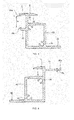
- FIG. 6 is a cross-sectional view showing a photovoltaic power generator according to a first embodiment of the present invention installed on a roof
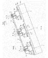
- FIG. 7 is a side view showing a photovoltaic power generator according to a first embodiment of the present invention installed on a roof.
- cross rails 6 serving as the base are secured to the roof 100 by fitting it with pressing fixtures 101 at a predetermined interval in the direction perpendicular to the inclination direction of the roof 100 (the direction from the eaves to the ridge).
- the pressing fixtures 101 are fixed to straight brackets 110 fixed to the roof 100 using nuts and bolts.
- the secured cross rails 6, 6 are parallel to each other and extend horizontally across the roof 100.
- the cross rails 6, 6 adjacent to each other in the inclination direction of the roof 100 are provided at an interval corresponding to the vertical width of the solar cell module 10 including the mounted frames 3, 4, 5 (the width in the inclination direction of the roof when installed on the roof 100).
- the lower frame 3 and upper frame 4 are fixed to the pair of cross rails 6, 6 to mount the solar cell module 10. As shown in FIG. 7 , in the solar cell module 10, the side frames 5 are mounted on the lower frame 3 and the upper frame 4 using screws 11.
- the upper flange 41 of the upper frame 4 of the solar cell module 10 positioned on the peak side of a cross rail 6 is placed on the frame mounting portion 62 of the cross rail 6 on the eaves side, and the frame mounting portion 62 of the cross rail 6 is interposed via the upper flange 41 between the upper and lower flanges 31, 34 of the lower frame 3, and the upper frame 4 and the lower frame 3 are secured. Because the upper frame 4 of the solar cell module 10 positioned on the eaves side is interposed by the lower frame 3 of the solar cell module 10 positioned on the peak side and secured to the cross rail 6, it is secured strongly against a load caused by the blowing wind.
- the flange 41 of the upper frame 4 is fixed to the cross rail 6 by a screw to further increase the fixing strength.
- a peak-side cover 17 is mounted by a screw 8 on the highest cross rail 6 arranged on the peak side, and an eaves-side cover 16 is mounted by a screw 7 on the lowest cross rail 6 arranged on the eaves side.
- the peak-side cover 17 has an upper and lower flange similar to the upper and lower flanges 31, 34 of the lower frame 3.
- the upper flange 41 of the upper frame 4 placed on the frame mounting portion 62 of the cross rail 6 is interposed by the upper and lower flanges of the peak-side cover 17, and the upper frame 4 is interposed in and secured to the cross rails 6. Because the upper frame 4 of the solar cell module 10 is interposed by the peak-side cover 17 and fixed to the cross rails 6, even the solar cell module 10 positioned closest to the ridge is secured strongly against a load caused by the blowing wind.
- FIG. 8 is a cross-sectional view of a cross rail.
- the rail 6 is made of aluminum, iron or stainless steel and can be extrusion molded.
- a frame mounting portion 62 is formed in the cross rail 6 and is connected to the top of the hollow main portion 60.
- the frame mounting portion 62 has an upper surface portion 66 in which the upper flange 41 of the upper rail 4 is placed, and an engaging portion 67 protruding towards the ridge in order to engage the upper and lower flanges 31, 34 of the lower frame 3.
- a groove 66a is formed in the upper surface portion 66 in which the upper flange 41 of the upper frame 4 is secured using a screw.
- the upper and lower flanges 31, 34 of the lower frame 3 engage the engaging portion 67, and the solar cell module 10 is rotated downward, dropped in, and engaged.
- a tapered surface 67a is provided in the engaging portion 67 extending from the peak side to the eaves side so that the lower flange 34 can be successfully dropped in.
- a contact surface 67b is formed in the base portion of the engaging portion 67 which comes into contact with the protruding portion 34a of the lower flange 34.
- the height h3 between the contact surface 67b and the upper surface portion 66 has dimensions which create a tight fit when the upper flange 41 of the upper frame 4 has been placed in the upper surface portion 66, and interposed between the upper and lower flanges 31, 34 of the lower frame 3.
- a recessed portion 67c is provided between the tapered surface 67a and the contact surface 67b.
- the recessed portion 67c engages the protruding portion 34a on the lower flange 34 of the lower frame 3.
- the protruding portion 34a engages the recessed portion 67c, the solar cell module 10 is kept from being lifted up.
- the side of the main portion 60 facing the ridge has an upper side portion 60a that makes contact with the lower side of the main portion 32 of the lower frame 3, an upper flange 60c that is connected to the upper side portion 60a.
- the upper flange 60c extends towards the side of the solar cell module 10 to keep the solar cell module 10 from falling onto the roof 100.
- the vertically positioned solar cell module 10 overlaps each frame and is sandwiched.
- the dimensions of the frame mounting portion 62 of the cross rail 6 can be narrowed in the inclination direction of the roof, and the distance between solar cell modules 10, 10 can be reduced.
- the size of the main portion 60 of the cross rail 6 can be reduced in the inclination direction of the roof, and the amount of material used can be reduced.
- the space required for installation of the solar cell modules 10 can be reduced on the surface of the roof. Alternately, more solar cell modules 10 can be installed in the same amount of space.
- the size of the upper side portion 60a of the main portion 60 is also reduced.
- the solar cell module 10 can be kept from falling onto the roof 100 because the upper flange 60c is connected to the side portion 60a.
- An upper side portion 60b is formed on the eaves side of the main portion 60 which comes into contact with the lower side of the main portion 42 of the upper frame 4.
- a groove 69 is also formed in main portion 60 on the eaves side to engage the rear end portion of the eaves-side cover 16.
- Lower flanges 61, 61 are provided on the lower end of the main portion 60 on both the eaves side and the peak side, and a protruding portion 61a extending upward is provided on the tip portion of both lower flanges 61, 61.
- a pressing fixture 101 is fitted into the protruding portion 61a of the lower flange 61, and the cross rail 6 is secured to the roof 100.
- a screw portion 65 is provided in the cross rail 6 to mount the cross rail cover.
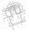
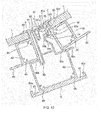
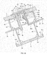
- FIG. 9 is an enlarged cross-sectional view showing the frame and cross rail of a solar cell module in a photovoltaic power generator according to a first embodiment of the present invention. The following is an explanation, with reference to FIG. 9 , of how the lower frame 3, upper frame 4, and cross rail 6 are secured with the solar cell module 10, 10 positioned vertically with respect to the cross rail 6.
- the lower side of the main portion 42 of the upper frame 4 of the solar cell module 10 positioned on the eaves side comes into contact with the upper end portion 60b of the main portion 60 of the cross rail 6, and the upper flange 41 of the upper frame 4 is placed on the upper surface portion 66 of the frame mounting portion 62 of the cross rail 6. Then, in the present embodiment, the upper surface portion 66 of the cross rail 6 and the upper flange 41 of the upper frame 4 of the solar cell module 10 positioned on the eaves side is fixed using screws 7.
- the engaging portion 67 provided on the frame mounting portion 62 of the cross rail 6 engages the upper and lower flanges 31, 34 of the lower frame 3 of the solar cell module 10 arranged on the peak side.
- the upper flange 41 of the upper frame 4 of the upper surface portion 66 is placed on the frame mounting portion 62.
- the lower flange 31 of the lower frame 3 engages the upper flange 41 of the upper frame 4.
- the solar cell module 10 arranged on the eaves side is rotated downwards and dropped in.
- the upper flange 41 of the upper frame 4 is interposed with the cross rail 6 by the upper and lower flanges 31, 34 of the lower frame 3, and the upper frame 4, the cross rail 6 and the lower frame 3 are secured.
- the lower flange 34 is smoothly dropped in along the tapered surface 67a from the peak side to the eaves side of the engaging portion 67, and the contact surface 67b of the base portion of the engaging portion 67 comes into contact with the protruding portion 34a of the lower flange 34.
- the protruding portion 31a of the upper flange 31 comes into contact with the surface of the upper flange 41 of the upper frame 4.
- the height h3 between the contact surface 67b and the upper surface portion 66 has dimensions which create a tight fit when the upper flange 41 of the upper frame 4 has been placed in the upper surface portion 66, and interposed between the upper and lower flanges 31, 34 of the lower frame 3.
- the height h1 between the protruding portions 31a, 34a is equal to or slightly smaller than the sum of the thickness h2 of the flange 41 of the upper frame 4 and the height h3 of the frame mounting portion 62 of the cross rail 6 so as to take into account the machining tolerance.
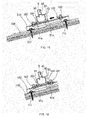
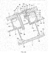
- FIG. 10 is an enlarged cross-sectional view showing the frame and cross rail of a solar cell module in a photovoltaic power generator according to a first embodiment of the present invention in which the solar cell module 10 has been lifted up by a load caused by the blowing wind.
- the following is an explanation, with reference to FIG. 10 , of how a solar cell module 10 is lifted up by a load caused by the blowing wind.
- the solar cell module 10 is lifted up by a load caused by the blowing wind.
- the protruding portion 34a of the lower flange 34 of the lower frame 3 becomes engaged in the recessed portion 67c before reaching the tapered surface 67a.
- the recessed portion 67c and the protruding portion 34a become engaged, upward movement of the solar cell module 10 is restricted, and the solar cell module 10 is kept from being lifted up by the wind.
- the upper frame 3 of the solar cell module 10 positioned on the eaves side is interposed with the cross rail 6 by the lower frame 3 of the solar cell module 10 on the peak side, it is secured strongly against loads caused by the blowing wind. Even when the solar cell module 10 is lifted up and moved upward on the cross rail 6, the recessed portion 67c and the protruding portion 34a restrict further movement, and the solar cell module 10 is kept from being lifted up further by the wind. When there is no load caused by the blowing wind, gravity disengages the protruding portion 34a from the recessed portion 67c, and the protruding portion moves towards the base portion of the engaging portion 67 and returns to the position shown in FIG. 9 .
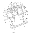
- FIG. 11 is an enlarged cross-sectional view showing the frame and cross rail of a solar cell module in a photovoltaic power generator according to a first embodiment of the present invention in which the solar cell module 10 has been moved towards the ridge by a load caused by the blowing wind.
- the following is an explanation, with reference to FIG. 11 , of a situation in which a solar cell module 10 has been moved towards the ridge by a load caused by the blowing wind.
- a straight bracket 110 is fixed to the roof 100 on a straight bracket marking 110a using screws 111.
- a metal base plate may be mounted on the roof 100 to secure the straight bracket 110.
- a pair of upside-down U-shaped pressing fixtures 101 is provided on the straight bracket 110.
- the pressing fixtures 101 can be moved along the gradient of the roof 100 by loosening the nut 102.
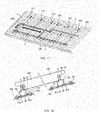
- a cross rail 6 is mounted. First, as shown in FIG. 13 , the end portion of the cross rail 6 is aligned with a vertical reference mark 110b and temporarily secured. When cross rails 6 are joined together, they are joined together using a cross rail joint which has a shape corresponding to the main portion 60 of the cross rails 6.
- the protruding portion 61a on the lower bracket 61 of the main portion 60 of the cross rail 6 positioned on the eaves side is fitted securely into the upside-down U-shaped portion of the pressing fixture 101, and the nut 102 is tightened.
- the pressing fixture 101 on the peak side is moved.
- the protruding portion 61a on the lower flange 61 on the peak side is fitted securely into the upside-down U-shaped portion of the pressing fixture 101, and the nut 102 is tightened.
- the cross rails 6 are secured at a predetermined pitch using a cross rail gauge 120. After all of the cross rails 6 have been secured, they are connected with screws when there is a connected portion in the cross rails 6 using a cross rail joint.
- a clip 123 for holding the cable 1f from the solar cell module 10 is mounted on the peak side of the cross rail 6.
- the cable 1f is held by this clip 123.
- a grounding wire 121 is mounted on the eaves side of the cross rail 6.
- the ground of the solar cell module 10 is connected via the cross rail 6.
- a grounding bracket is pressed into a space between the cross rail 6 and the lower frame 3 of the solar cell module 10 to connect cross rails 6, 6.
- line 122 is used to guide the cables If.
- an eaves-side cover 16 is mounted on the cross rail 6 closest to the eaves.
- the rear end portion of the eaves-side cover 16 is engaged with a groove in the main portion 60 of the cross rail 6, and the eaves-side cover 16 is mounted on the cross rail 6 with screws 7.
- solar cell modules 10 are mounted on the cross rails 6, 6.
- the lower frame 3 side of the solar cell module 10 is placed on the cross rail 6 on the eaves side.
- the protruding portion 31a of the upper flange 31 of the lower frame 3 is placed on the upper surface portion 66 of the frame mounting portion 62 of the cross rail 6 on the eaves side.
- the solar cell module 10 is tilted downward onto the roof 100, the solar cell module 10 is dropped in, and the engaging portion 67 of the frame mounting portion 62 of the cross rail 6 is interposed by the upper and lower flanges 31, 34 of the lower frame 3.
- the upper flange 41 of the upper frame 4 is placed on the upper surface portion 66 of the frame mounting portion 62 of the cross rail 6 on the peak side.
- the solar cell module 10 is raised towards the eaves side.
- a second solar cell module 10 is mounted in the same way and the cables If, If are connected.
- fine adjustments are made in the positioning when the wiring of a solar cell module 10 has been completed on each level.
- the upper flange 41 of the upper frame 4 of the solar cell module 10 and the cross rail 6 are secured using screws 7.
- each solar cell module 10 is secured using five screws 7.
- a photovoltaic power generator comprising solar cell modules 10 and cross rails 6 serving as the base, all of the solar cell modules 10 are grounded.
- Each solar cell module 10 may be grounded by installing a grounding wire, but this increases material costs and complicates installation by increasing the number of steps. Therefore, the photovoltaic power generator can be integrated electrically and grounded using a single grounding wire 121.
- each solar cell module 10 is secured to a cross rail 6 using metal screws 7 to integrate the modules electrically.
- the lower rail 3 of each solar cell module 10 is separate from the rail electrically. Therefore, they need to be integrated electrically.
- a grounding bracket with several protrusions is pressed into the space between the cross rail 6 and the lower frame 3 to connect the lower frame 3 and the cross rail 6 electrically.
- the joints fitted to inside the cross rails 6 to connect the cross rails 6 are also secured using screws to integrate them electrically.
- the solar cell module 10 is mounted on the cross rail 6 positioned on the eaves side from the ridge side with respect to the cross rail 6.
- the lower frame 3 of the solar cell module 10 is placed on the upper flange 41 of the upper frame 4 of the lower-level solar cell module 10 placed on the eaves-side cross rail 6.
- the protruding portion 31a of the upper flange 31 of the lower frame 3 is placed on the upper flange 41 of the upper frame 4 of the lower-level solar cell module 10 mounted on the upper surface portion 66 of the frame mounting portion 62 of the cross rail 6.
- the solar cell module 10 is tilted downward towards the roof 100, the solar cell module 10 is dropped in, the frame mounting portion 62 of the cross rail 6 is interposed via the upper flange 41 between the upper and lower flanges 31, 34 of the lower frame 3, and the upper frame 4 and lower frame 3 are secured.
- the upper flange 41 of the upper frame 4 is then placed on the upper surface portion 66 of the frame mounting portion 62 of the cross rail 6 on the ridge side. Afterwards, the solar cell module 10 is tilted upward towards the eaves.
- the worker is on the roof 100 behind the solar cell module 10 on the ridge side, and holds and fits the solar cell module 10 while facing the eaves side. Because the installation is performed from behind on the ridge side, the worker is able to keep his or her balance on the roof 100 while installing modules.
- the upper flange 41 of the upper frame 4 is interposed between the upper and lower flanges of the ridge-side cover 17 on the uppermost cross rail 6, and the ridge-side cover 17 is secured using screws 8.
- a grounding bracket 19 is inserted into the space between the cross rail 6 and the solar cell module 10 on the eaves side, that is, into the space between the cross rail 6 and the lower frame 3 to electrically integrate the components.
- a cross rail cover 18 is secured to the end portion of the cross rail 6 using screws 18a, and the photovoltaic power generator has been installed on the roof 100.
- a grounding bracket 19 is mounted between a cross rail 6 and a lower frame 3 with reference to FIG. 34 through FIG. 36 .
- the grounding bracket 19 is shaped so that it can be inserted into the space 19d between the cross rail 6 and the lower frame 3.
- a space 19d with a downward-facing triangular shape is formed between the lower portion of the engaging portion 67 of the cross rail 6 and the lower flange 34 of the lower frame 3.
- a U-shaped grounding bracket 19 is formed which conforms to the downward-facing triangular shape of this space.
- a plurality of claw portions 19a are provided on the surface of the grounding bracket 19.
- FIG. 39 is a cross-sectional view showing a photovoltaic power generator according to a second embodiment of the present invention installed on a roof
- FIG. 40 is an enlarged cross-sectional view showing a frame and cross rail of a solar cell module for a photovoltaic power generator according to a second embodiment of the present invention. All components that are identical or equivalent in function to those of the first embodiment are denoted by the same reference numbers in the drawings, and the explanation of these components has not been repeated in order to avoid redundancy.
- the upper flange 41 of the upper frame 4 is secured to the cross rail 6 using screws.
- screws are not used.
- the engaging portion 67 of the cross rail 6 is interposed via the upper flange 41 between the upper and lower flanges 31, 34 of the lower frame 3, and the resulting fastening force secures the upper frame 4 and the lower frame 3.
- the dimensions between the upper and lower flanges 31, 34 are set to increase the fastening force, and this force is strong enough to provide a pressing load that can withstand a load caused by the blowing wind even through screws have been omitted.
- the modules are easier to install because screws are not required.
- an insulating cover is formed on the surface.
- the upper flange 41 does not come into direct contact with the upper surface portion 66 of the cross rail 6, and the components are not grounded.
- the upper surface portion 66 and the upper flange 41 can be connected and grounded using a star washer, or each solar cell module 10 can be connected and grounded using a single screw.
- FIG. 41 is an enlarged cross-sectional view showing a frame and cross rail of a solar cell module for a photovoltaic power generator according to a third embodiment of the present invention. All components that are identical or equivalent in function to those of the first embodiment are denoted by the same reference numbers in the drawing, and the explanation of these components has not been repeated in order to avoid redundancy.
- FIG. 42 is an enlarged cross-sectional view showing a frame and cross rail of a solar cell module for a photovoltaic power generator according to a fourth embodiment of the present invention. All components that are identical or equivalent in function to those of the first embodiment are denoted by the same reference numbers in the drawing, and the explanation of these components has not been repeated in order to avoid redundancy.
- a protrusion is not provided on the tip of the upper flange 41 of the upper frame 4 and the upper flange 31 of the lower frame 41.
- protrusions are not provided, but the surfaces of the upper flange 41 of the upper frame 4 and the upper flange 31 of the lower frame 3 come into contact and are interposed. This can suppress upward rotation of the solar cell module 10 when there is a load caused by the blowing wind.
- the embodiment shown in FIG. 42 does not have a recessed portion 67c provided in the engaging portion 67, but a recessed portion 67c may be provided.
- the present invention can be applied to solar cell modules for converting solar energy to electrical energy, photovoltaic power generators in which these solar cell modules have been installed on the roof of a building to generate power, and frames used to support these solar cell modules.
Landscapes
- Engineering & Computer Science (AREA)
- Chemical & Material Sciences (AREA)
- Mechanical Engineering (AREA)
- Sustainable Development (AREA)
- Sustainable Energy (AREA)
- Thermal Sciences (AREA)
- Physics & Mathematics (AREA)
- Combustion & Propulsion (AREA)
- Life Sciences & Earth Sciences (AREA)
- General Engineering & Computer Science (AREA)
- Architecture (AREA)
- Civil Engineering (AREA)
- Structural Engineering (AREA)
- Roof Covering Using Slabs Or Stiff Sheets (AREA)
- Photovoltaic Devices (AREA)
Abstract
The present invention provides a device whereby, without causing an increase in the number of components, it is possible to perform an installation task without resting on a solar cell module when working. The present invention has: a horizontal crosspiece (6), wherein a frame attachment section (62) is formed; a rectangular solar cell panel (1); and a solar cell module (10) provided with an top side frame (4), which is attached to the top side of the solar cell panel (1) and has an upper flange (41) carried on the upper surface of the frame attachment section (62), and a bottom side frame (3), which is attached to the bottom side of the solar cell panel (1) and has an upper and lower flange (31, 34) that extend towards eaves. A pair of the horizontal crosspieces (6, 6) are installed on a roof at a predetermined spacing, the upper flange (41) of the top side frame (4) of the solar cell module (10) disposed on the eaves side is placed on the upper surface (66) of the attachment section (62), and the upper flange (41) of the top side frame (4) is affixed sandwiched against the attachment section (62) by the upper and lower flanges (31, 34) of the bottom side frame (3) of the solar cell module (10) on the roof ridge side.
Description
- The present invention relates to a solar cell module whose frame is mounted around a module unit for producing photovoltaic power, and to a photovoltaic power generator in which these solar cell modules are arranged side by side on the roof of a building.
- In a photovoltaic power generator installed on the roof of a building, a frame made of steel or aluminum is mounted on the roof, and a plurality of solar cell modules are attached to this frame.
- Many methods have been proposed for mounting solar cell modules on a roof. In
Patent Document 1, a photovoltaic power generator has been proposed in which solar cell modules can be easily installed on a roof without stepping on the solar cell modules. - The photovoltaic power generator described in
Patent Document 1 will now be explained with reference toFIG. 43 . - As shown in
FIG. 43 , thecover member 203 facing the eaves and thecover member 204 facing the ridge for thesolar cell module 250 have different shapes. Thecover member 203 facing the eaves supports thesolar cell panel 201 and has anupper flange 203a provided on the light-receiving side 208. Thecover member 204 facing the ridge supports thesolar cell panel 201 and has anupper flange 204a provided on the light-receiving side 208 and alower flange 204b provided on the non-light-receivingside 209 of the solar cell module. - The cross-sectional structure of the
horizontal rack 207 serving as the frame has a receivingportion 231 facing the eaves for receiving theupper flange 203a of thecover member 203. It also has a recessedportion 207b facing the ridge in which theupper flange 204a and a protrudingportion 204c of thecover member 204 are fitted. In addition, it has a protrudingportion 207h capable of supporting the base portion of theupper flange 204a of thecover member 204. Thehorizontal rack 207 also has arecessed portion 207a for accommodating thelower flange 204b of thecover member 204. Therecessed portions portion 207c of the base portion. - Protruding
portions horizontal rack 207, which have a structure into which the protrudingportions clamping member 206 can be fitted. - A
space 215 is provided in the upper surface of thehorizontal rack 207 for ascrew 205 to pass through. - The following is a brief explanation of the method used to mount a
solar cell module 250 with this structure on ahorizontal rack 207. A U-shaped space is formed by theupper flange 204a, thelower flange 204b and avertical wall portion 204d of thecover member 204 of thesolar cell module 250 facing the eaves. A portion of the upper surface of thehorizontal rack 207 facing the ridge (the uppersurface protruding portion 207h facing the ridge) is inserted into this space and comes into contact with the inner walls of the space. By tilting the side of thesolar cell module 250 facing the surface of the roof around a center line passing through the points of contact, the tip portion of theupper flange 204a can be directed into therecessed portion 207b of thehorizontal rack 207, and the tip portion of theupper flange 204a can be rotated around the center line to move thesolar cell module 250 closer to theroof surface 212. - The tip portion of the
protruding portion 204c provided in the middle of theupper flange 204a then comes into contact with thegroove portion 207b in the upper surface of thehorizontal rack 207 facing the ridge, the tip portion of theprotruding portion 204c is rotated around the center line, and thesolar cell module 250 is rotated. - After the tip portion of the
protruding portion 204c in the middle of theupper flange 204a of thecover portion 204 facing the eaves begins to rotate, thesolar cell module 250 is fitted into thehorizontal rack 207 so that the tip portion of thelower flange 204b is close to the upper surface of therecessed portion 207a. - The
upper flange 203a of thecover member 203 of thesolar cell module 250 facing the ridge is then received and secured by thereceiving portion 231 of thehorizontal rack 7. The protrudingportions clamping member 206 are fitted into theprotruding portions horizontal rack 207, and theclamping member 206 and thecover member 203 facing the ridge are secured using ascrew 205. Theclamping member 206 and thecover member 203 facing the ridge are secured with thescrew 205 until thecover member 204 of thesolar cell module 250 facing the eaves has been mounted. - Patent Document 1: Laid-Open Patent Application No.
2007-266446 - In this photovoltaic power generator, the
clamping member 206 is mounted before thecover member 204 of thesolar cell module 250 facing the eaves has been mounted. In order to mount theclamping member 206, thesolar cell module 250 has to be straddled, and the installer has to be very skillful in order to install the photovoltaic power generator without stepping on thesolar cell modules 250. - In this photovoltaic power generator, the
solar cell module 250 is clamped and secured to thehorizontal rack 207 serving as the base using aclamping member 206. As a result, a separate clamping member is required in addition to the frame and the solar cell module. This increases the number of parts. - The present invention provides a device which does not increase the number of parts, and which can be installed without the installer stepping on the solar cell module.
- The present invention is a solar cell module installed between a pair of cross rails on which a frame mounting portion has been provided. The solar cell module comprises a rectangular solar cell panel, an upper frame having an upper flange mounted on an upper side of the solar cell panel and placed on the upper surface portion of the frame mounting portion, and a lower frame mounted on a lower side of the solar cell panel and having upper and lower flanges extending on the side facing the ridge. The upper flange of the upper frame of the solar cell module arranged on the side facing the eaves is interposed in the mounting portion by the upper and lower flanges.
- The present invention is also a photovoltaic power generator installed on the roof of a building which comprises a cross rail having a frame mounting portion, and a solar cell module including: a rectangular solar cell panel; an upper frame having an upper flange, the upper frame being mounted on the upper side of the solar cell panel and placed on the upper surface portion of the frame mounting portion; and a lower frame mounted on a lower side of the solar cell panel and having upper and lower flanges extending on the side facing the ridge. A pair of cross rails is installed on the roof at a predetermined interval, the upper flange of the upper frame is placed on the upper surface portion of the mounted portion, and the upper flange of the upper frame is interposed and secured in the mounted portion by the upper and lower flanges of the lower frame of the solar cell module on the side facing the ridge.
- In the present invention, the frame mounting portion of a cross rail is interposed between upper and lower flanges of a lower frame via the upper flange of the upper frame of the solar cell module positioned on the eaves side of the cross rail in order to secure the upper frame and the lower frame. As a result, the solar cell module is secured strongly against a load caused by the blowing wind.
-
-
FIG. 1 is a top view showing a solar cell module according to an embodiment of the present invention from the light-receiving side. -
FIG. 2 is a rear view showing a solar cell module according to an embodiment of the present invention from the back side. -
FIG. 3 is a cross-sectional view showing the lower frame used by a solar cell module according to a first embodiment of the present invention. -
FIG. 4 is a cross-sectional view showing the upper frame used by a solar cell module according to a first embodiment of the present invention. -
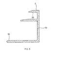
FIG. 5 is a cross-sectional view showing the side frame used by a solar cell module according to an embodiment of the present invention. -
FIG. 6 is a cross-sectional view showing a photovoltaic power generator according to a first embodiment of the present invention installed on a roof. -
FIG. 7 is a side view showing a photovoltaic power generator according to a first embodiment of the present invention installed on a roof. -
FIG. 8 is a cross-sectional view showing a cross rail used by a photovoltaic power generator according to an embodiment of the present invention. -
FIG. 9 is an enlarged cross-sectional view showing the frame and cross rail of a solar cell module in a photovoltaic power generator according to a first embodiment of the present invention. -
FIG. 10 is an enlarged cross-sectional view showing the frame and cross rail of a solar cell module in a photovoltaic power generator according to a first embodiment of the present invention in which the solar cell module has been lifted up by a load caused by the blowing wind. -
FIG. 11 is an enlarged cross-sectional view showing the frame and cross rail of a solar cell module in a photovoltaic power generator according to a first embodiment of the present invention in which the solar cell module has been moved towards the ridge by a load caused by the blowing wind. -
FIG. 12 is a perspective view showing a straight bracket mounted on a roof to secure a cross rail used by the present invention. -
FIG. 13 is a perspective view showing a cross rail used by the present invention which has been temporarily secured to a straight bracket mounted on a roof. -
FIG. 14 is a cross-sectional view showing a cross rail used by the present invention which has been temporarily secured to a straight bracket mounted on a roof. -
FIG. 15 is a cross-sectional view showing a cross rail used by the present invention which has been temporarily secured to a straight bracket mounted on a roof. -
FIG. 16 is a cross-sectional view showing a cross rail used by the present invention which has been secured to a straight bracket mounted on a roof. -
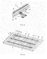
FIG. 17 is a perspective view showing a cross rail used by the present invention which has been positioned using a cross rail gauge and temporarily secured to straight brackets mounted on a roof. -
FIG. 18 is a cross-sectional view showing a cross rail used by the present invention which has been positioned using a cross rail gauge and temporarily secured to straight brackets mounted on a roof. -
FIG. 19 is a perspective view showing a cross rail used by the present invention which has been secured using a cable clip to a straight bracket mounted on a roof. -
FIG. 20 is a perspective view showing a cross rail used by the present invention which has been mounted on a roof. -
FIG. 21 is a perspective view showing an eaves-side cover attached to a cross rail used by the present invention which has been mounted on a roof. -
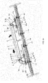
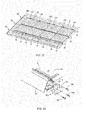
FIG. 22 is a perspective view showing a solar cell module mounted on a cross rail used by the present invention which has been mounted on a roof. -
FIG. 23 is a cross-sectional view showing a solar cell module mounted on a cross rail used by the present invention which has been mounted on a roof. -
FIG. 24 is a cross-sectional view showing a solar cell module mounted on a cross rail used by the present invention which has been mounted on a roof. -
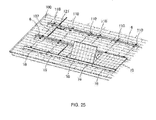
FIG. 25 is a perspective view showing a solar cell module mounted on a cross rail used by the present invention which has been mounted on a roof. -
FIG. 26 is a perspective view showing a solar cell module mounted on a cross rail used by the present invention which has been mounted on a roof. -
FIG. 27 is a perspective view showing a solar cell module mounted on a cross rail used by the present invention which has been mounted on a roof. -
FIG. 28 is a cross-sectional view showing a solar cell module mounted on a cross rail used by the present invention which has been mounted on a roof. -
FIG. 29 is a cross-sectional view showing a solar cell module mounted on a cross rail used by the present invention which has been mounted on a roof. -
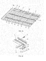
FIG. 30 is a perspective view showing a peak-side cover attached to a cross rail used by the present invention which has been mounted on a roof. -
FIG. 31 is a perspective view showing a peak-side cover attached to a cross rail used by the present invention which has been mounted on a roof. -
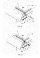
FIG. 32 is a perspective view showing a grounding bracket attached to a cross rail used by the present invention which has been mounted on a roof. -
FIG. 33 is a perspective view showing a grounding bracket attached to a cross rail used by the present invention which has been mounted on a roof. -
FIG. 34 is a front view of a grounding bracket used in the present invention. -
FIG. 35 is a top view of a grounding bracket used in the present invention. -
FIG. 36 is a cross-sectional view showing a grounding bracket attached to a cross rail used by the present invention which has been mounted on a roof. -
FIG. 37 is a perspective view showing a cross rail cover attached to a cross rail used by the present invention which has been mounted on a roof. -
FIG. 38 is a perspective view showing a cross rail cover attached to a cross rail used by the present invention which has been mounted on a roof. -
FIG. 39 is a cross-sectional view showing a photovoltaic power generator according to a second embodiment of the present invention installed on a roof. -
FIG. 40 is an enlarged cross-sectional view showing a frame and cross rail of a solar cell module for a photovoltaic power generator according to a second embodiment of the present invention. -
FIG. 41 is an enlarged cross-sectional view showing a frame and cross rail of a solar cell module for a photovoltaic power generator according to a third embodiment of the present invention. -
FIG. 42 is an enlarged cross-sectional view showing a frame and cross rail of a solar cell module for a photovoltaic power generator according to a fourth embodiment of the present invention. -
FIG. 43 is an enlarged cross-sectional view showing a cover member, horizontal rack, and clamping member of a solar cell module of the prior art. - The following is a detailed explanation of embodiments of the present invention with reference to the drawings. All components that are identical or equivalent in function are denoted by the same reference numbers in the drawings, and the explanation of these components has not been repeated in order to avoid redundancy.
- As shown in
FIG. 1 , thesolar cell module 10 of the present invention has a rectangularsolar cell panel 1, and frames 3, 4, 5 mounted on the peripheral edges of thesolar cell panel 1. - A
lower frame 3 is mounted on one long side of thesolar cell panel 1. Thelower frame 3 is mounted on the side of the roof facing the eaves. Anupper frame 4 is mounted on the other long side of thesolar cell panel 1. Theupper frame 4 is mounted on the side of the roof facing the ridge. Side frames 5 are provided on the short sides of thesolar cell panel 1. - The
lower frame 3, theupper frame 4 and the side frames 5 are connected to each other at their end points in the longitudinal direction. Theseframes solar cell panel 1. Thesolar cell module 1 is mounted on installation cross rails 6 as described below. The length of the side frames 5 is approximately 800 mm, and the length of thelower frame 3 and theupper frame 4 is from 1500 mm to 1600 mm. However, the present invention is not limited to this example, and the frames can be of any size. - The shape of the
solar cell panel 1 is rectangular when viewed from above. As shown inFIG. 1 , thesolar cell panel 1 has a plurality ofsolar cells 1a connected to each other electrically viawiring material 1b, and sealed between a transparent surface member and weather-resistant backing member using a transparent sealing material with superior weather- and moisture-resistance such as EVA (ethylene vinyl acetate copolymer resin). - The
solar cells 1a are connected in series usingwiring material 1b to form a string which functions as a single unit. Connection wiring such as transition wiring 1c is used to connect the strings. Alead wire 1d is also connected to draw power from thesolar cells 1a. - The
solar cells 1a are 100-mm square crystalline semiconductors with a thickness of 0.15 mm made of single-crystal silicon or polycrystalline silicon. The present invention is not limited to this example. Other types of solar cells can be used. - Each
solar cell 1a can have an n-type region and a p-type region, and a junction portion forming an electric field for separating carriers in the boundary portion between the n-type region and the p-type region. Thesolar cells 1a may be back junction-type solar cells with the n-type region and p-type region on the back side. - The surface member is a transparent panel allowing light to pass into the
solar cell 1a. Examples include glass panels such as white glass, tempered glass and heat-reflecting glass, and panels made of synthetic resins such as polycarbonate resin. - The backing member may be made of polyvinyl fluoride (PVF), polyethylene terephthalate (PET), polyethylene naphthalate (PEN), a laminate thereof, or aluminum foil sandwiched between sheets of PET film.
- The
solar cell module 10 is fitted between theframes solar cell panel 1. - Also, as shown in
FIG. 2 , aterminal box 1e is mounted on the back side of thesolar cell module 10, and power generated by thesolar cell panel 1 is supplied from theterminal box 1e tocables - As shown in
FIG. 3 through FIG. 5 , thelower frame 3, theupper frame 4 and theside frame 5 can be made of aluminum, ion or stainless steel, and can be extrusion molded. - As shown in
FIG. 3 , thelower frame 3 has a hollowmain portion 32, and afitting portion 30 with a C-shaped cross-section positioned in the upper portion of themain portion 32 with packing made of an insulating resin such as butyl rubber or silicone resin on the peripheral edges of thesolar cell panel 1. - An
upper flange 31 is provided on thelower frame 3 and connected to the upper side of thefitting portion 30 for engaging the frame mounting portion on across rail 6 described below. A protrudingportion 31a extending downward is provided on the tip of theupper flange 31. In the middle of themain portion 32, alower flange 34 is provided which faces theupper flange 31, and a protrudingportion 34a extending upward is provided on the tip of thelower flange 34. - Also, a
flange 33 connected to the lower side of themain portion 32 and extending towards thesolar cell panel 1 is provided in themain portion 32. Ascrew portion 35 is provided in themain portion 32 for mounting aside frame 5. Thelower frame 3 and aside frame 5 are fixed by passing a screw through theside frame 5 and screwing it into thescrew portion 35. - As shown in
FIG. 4 , theupper frame 4 has a hollowmain portion 42, and afitting portion 40 with a C-shaped cross-section positioned in the upper portion of themain portion 42 with packing made of an insulating resin such as butyl rubber or silicone resin on the peripheral edges of thesolar cell panel 1. - An
upper flange 41 is provided in theupper frame 4 which is connected to the upper side of thefitting portion 40, placed on theframe mounting portion 62 of across rail 6, and interposed in thelower frame 31. The protrudingportion 41a which extends upward is provided on the tip of theupper flange 41. - Also, a
flange 43 connected to the lower side of themain portion 42 and extending towards thesolar cell panel 1 is provided in themain portion 42. Ascrew portion 45 is provided in themain portion 42 for mounting aside frame 5. Theupper frame 4 and aside frame 5 are fixed by passing a screw through theside frame 5 and screwing it into thescrew portion 45. - As shown in
FIG. 5 , eachside frame 5 has amain portion 52, and afitting portion 50 with a C-shaped cross-section positioned in the upper portion of themain portion 52 with packing made of an insulating resin such as butyl rubber or silicone resin on the peripheral edges of thesolar cell panel 1. - A
flange 52 is provided on the lower side of themain portion 52 that extends towards thesolar cell panel 1. -
FIG. 6 is a cross-sectional view showing a photovoltaic power generator according to a first embodiment of the present invention installed on a roof, andFIG. 7 is a side view showing a photovoltaic power generator according to a first embodiment of the present invention installed on a roof. - As shown in
FIG. 6 andFIG. 7 , cross rails 6 serving as the base are secured to theroof 100 by fitting it withpressing fixtures 101 at a predetermined interval in the direction perpendicular to the inclination direction of the roof 100 (the direction from the eaves to the ridge). Thepressing fixtures 101 are fixed tostraight brackets 110 fixed to theroof 100 using nuts and bolts. - The
secured cross rails roof 100. The cross rails 6, 6 adjacent to each other in the inclination direction of theroof 100 are provided at an interval corresponding to the vertical width of thesolar cell module 10 including the mountedframes - The
lower frame 3 andupper frame 4 are fixed to the pair ofcross rails solar cell module 10. As shown inFIG. 7 , in thesolar cell module 10, the side frames 5 are mounted on thelower frame 3 and theupper frame 4 using screws 11. - The
upper flange 41 of theupper frame 4 of thesolar cell module 10 positioned on the peak side of across rail 6 is placed on theframe mounting portion 62 of thecross rail 6 on the eaves side, and theframe mounting portion 62 of thecross rail 6 is interposed via theupper flange 41 between the upper andlower flanges lower frame 3, and theupper frame 4 and thelower frame 3 are secured. Because theupper frame 4 of thesolar cell module 10 positioned on the eaves side is interposed by thelower frame 3 of thesolar cell module 10 positioned on the peak side and secured to thecross rail 6, it is secured strongly against a load caused by the blowing wind. - In the first embodiment shown in
FIG. 6 andFIG. 7 , theflange 41 of theupper frame 4 is fixed to thecross rail 6 by a screw to further increase the fixing strength. - A peak-
side cover 17 is mounted by ascrew 8 on thehighest cross rail 6 arranged on the peak side, and an eaves-side cover 16 is mounted by ascrew 7 on thelowest cross rail 6 arranged on the eaves side. The peak-side cover 17 has an upper and lower flange similar to the upper andlower flanges lower frame 3. Theupper flange 41 of theupper frame 4 placed on theframe mounting portion 62 of thecross rail 6 is interposed by the upper and lower flanges of the peak-side cover 17, and theupper frame 4 is interposed in and secured to the cross rails 6. Because theupper frame 4 of thesolar cell module 10 is interposed by the peak-side cover 17 and fixed to the cross rails 6, even thesolar cell module 10 positioned closest to the ridge is secured strongly against a load caused by the blowing wind. - The following is an explanation of the cross rails 6 with reference to
FIG. 8. FIG. 8 is a cross-sectional view of a cross rail. As shown inFIG. 8 , therail 6 is made of aluminum, iron or stainless steel and can be extrusion molded. - A
frame mounting portion 62 is formed in thecross rail 6 and is connected to the top of the hollowmain portion 60. Theframe mounting portion 62 has anupper surface portion 66 in which theupper flange 41 of theupper rail 4 is placed, and an engagingportion 67 protruding towards the ridge in order to engage the upper andlower flanges lower frame 3. Agroove 66a is formed in theupper surface portion 66 in which theupper flange 41 of theupper frame 4 is secured using a screw. - The upper and
lower flanges lower frame 3 engage the engagingportion 67, and thesolar cell module 10 is rotated downward, dropped in, and engaged. Atapered surface 67a is provided in the engagingportion 67 extending from the peak side to the eaves side so that thelower flange 34 can be successfully dropped in. Acontact surface 67b is formed in the base portion of the engagingportion 67 which comes into contact with the protrudingportion 34a of thelower flange 34. As mentioned earlier, the height h3 between thecontact surface 67b and theupper surface portion 66 has dimensions which create a tight fit when theupper flange 41 of theupper frame 4 has been placed in theupper surface portion 66, and interposed between the upper andlower flanges lower frame 3. - A recessed
portion 67c is provided between thetapered surface 67a and thecontact surface 67b. When thesolar cell module 10 has been moved in an upward direction, the recessedportion 67c engages the protrudingportion 34a on thelower flange 34 of thelower frame 3. When the protrudingportion 34a engages the recessedportion 67c, thesolar cell module 10 is kept from being lifted up. - The side of the
main portion 60 facing the ridge has anupper side portion 60a that makes contact with the lower side of themain portion 32 of thelower frame 3, anupper flange 60c that is connected to theupper side portion 60a. When thesolar cell module 10 is secured, theupper flange 60c extends towards the side of thesolar cell module 10 to keep thesolar cell module 10 from falling onto theroof 100. - In the present invention, the vertically positioned
solar cell module 10 overlaps each frame and is sandwiched. As a result, the dimensions of theframe mounting portion 62 of thecross rail 6 can be narrowed in the inclination direction of the roof, and the distance betweensolar cell modules solar cell modules main portion 60 of thecross rail 6 can be reduced in the inclination direction of the roof, and the amount of material used can be reduced. Also, the space required for installation of thesolar cell modules 10 can be reduced on the surface of the roof. Alternately, moresolar cell modules 10 can be installed in the same amount of space. - When the size of the
main portion 60 of thecross rail 6 is reduced relative to the inclination direction of the roof, the size of theupper side portion 60a of themain portion 60 is also reduced. However, in the present embodiment, as mentioned earlier, thesolar cell module 10 can be kept from falling onto theroof 100 because theupper flange 60c is connected to theside portion 60a. - An
upper side portion 60b is formed on the eaves side of themain portion 60 which comes into contact with the lower side of themain portion 42 of theupper frame 4. Agroove 69 is also formed inmain portion 60 on the eaves side to engage the rear end portion of the eaves-side cover 16. -
Lower flanges main portion 60 on both the eaves side and the peak side, and a protrudingportion 61a extending upward is provided on the tip portion of bothlower flanges pressing fixture 101 is fitted into the protrudingportion 61a of thelower flange 61, and thecross rail 6 is secured to theroof 100. - A
screw portion 65 is provided in thecross rail 6 to mount the cross rail cover. -
FIG. 9 is an enlarged cross-sectional view showing the frame and cross rail of a solar cell module in a photovoltaic power generator according to a first embodiment of the present invention. The following is an explanation, with reference toFIG. 9 , of how thelower frame 3,upper frame 4, and crossrail 6 are secured with thesolar cell module cross rail 6. - The lower side of the
main portion 42 of theupper frame 4 of thesolar cell module 10 positioned on the eaves side comes into contact with theupper end portion 60b of themain portion 60 of thecross rail 6, and theupper flange 41 of theupper frame 4 is placed on theupper surface portion 66 of theframe mounting portion 62 of thecross rail 6. Then, in the present embodiment, theupper surface portion 66 of thecross rail 6 and theupper flange 41 of theupper frame 4 of thesolar cell module 10 positioned on the eaves side is fixed usingscrews 7. - The engaging
portion 67 provided on theframe mounting portion 62 of thecross rail 6 engages the upper andlower flanges lower frame 3 of thesolar cell module 10 arranged on the peak side. - The
upper flange 41 of theupper frame 4 of theupper surface portion 66 is placed on theframe mounting portion 62. Next, thelower flange 31 of thelower frame 3 engages theupper flange 41 of theupper frame 4. When thelower flange 31 has engaged theupper flange 41, thesolar cell module 10 arranged on the eaves side is rotated downwards and dropped in. In this way, theupper flange 41 of theupper frame 4 is interposed with thecross rail 6 by the upper andlower flanges lower frame 3, and theupper frame 4, thecross rail 6 and thelower frame 3 are secured. - The
lower flange 34 is smoothly dropped in along the taperedsurface 67a from the peak side to the eaves side of the engagingportion 67, and thecontact surface 67b of the base portion of the engagingportion 67 comes into contact with the protrudingportion 34a of thelower flange 34. The protrudingportion 31a of theupper flange 31 comes into contact with the surface of theupper flange 41 of theupper frame 4. As mentioned earlier, the height h3 between thecontact surface 67b and theupper surface portion 66 has dimensions which create a tight fit when theupper flange 41 of theupper frame 4 has been placed in theupper surface portion 66, and interposed between the upper andlower flanges lower frame 3. - The height h1 between the protruding
portions flange 41 of theupper frame 4 and the height h3 of theframe mounting portion 62 of thecross rail 6 so as to take into account the machining tolerance. When theflange 41 of theupper frame 4 has been interposed in theframe mounting portion 62 of thecross rail 6, it is secured between the upper andlower flanges lower frame 31 because of the tight fit. Because theupper frame 3 of thesolar cell module 10 positioned on the eaves side is interposed with thecross rail 6 by thelower frame 3 of thesolar cell module 10 positioned on the peak side, it is secured strongly against lift caused by the blowing wind. -
FIG. 10 is an enlarged cross-sectional view showing the frame and cross rail of a solar cell module in a photovoltaic power generator according to a first embodiment of the present invention in which thesolar cell module 10 has been lifted up by a load caused by the blowing wind. The following is an explanation, with reference toFIG. 10 , of how asolar cell module 10 is lifted up by a load caused by the blowing wind. - The
solar cell module 10 is lifted up by a load caused by the blowing wind. However, even when thelower flange 34 of thelower frame 3 has moved along the engagingportion 67 of theframe mounting portion 62, the protrudingportion 34a of thelower flange 34 of thelower frame 3 becomes engaged in the recessedportion 67c before reaching thetapered surface 67a. When the recessedportion 67c and the protrudingportion 34a become engaged, upward movement of thesolar cell module 10 is restricted, and thesolar cell module 10 is kept from being lifted up by the wind. - Because the
upper frame 3 of thesolar cell module 10 positioned on the eaves side is interposed with thecross rail 6 by thelower frame 3 of thesolar cell module 10 on the peak side, it is secured strongly against loads caused by the blowing wind. Even when thesolar cell module 10 is lifted up and moved upward on thecross rail 6, the recessedportion 67c and the protrudingportion 34a restrict further movement, and thesolar cell module 10 is kept from being lifted up further by the wind. When there is no load caused by the blowing wind, gravity disengages the protrudingportion 34a from the recessedportion 67c, and the protruding portion moves towards the base portion of the engagingportion 67 and returns to the position shown inFIG. 9 . -
FIG. 11 is an enlarged cross-sectional view showing the frame and cross rail of a solar cell module in a photovoltaic power generator according to a first embodiment of the present invention in which thesolar cell module 10 has been moved towards the ridge by a load caused by the blowing wind. The following is an explanation, with reference toFIG. 11 , of a situation in which asolar cell module 10 has been moved towards the ridge by a load caused by the blowing wind. - When a
solar cell module 10 has been moved towards the ridge by a load caused by the blowing wind, the protrudingportion 31a of theupper flange 31 of thelower frame 3 engages the protrudingportion 41 a of theupper flange 41 of theupper frame 4 of thesolar cell module 10 positioned on the eave side and fixed to theframe mounting portion 62 of thecross rail 6. When the protrudingportion 41a of theupper frame 4 engages the protrudingportion 31a of thelower frame 3, movement of thesolar cell module 10 is suppressed. When there is no load caused by the blowing wind, gravity returns the configuration to the state shown inFIG. 9 . - The following is an explanation, with reference to
FIG. 12 through FIG. 38 , of the steps performed to install a solar cell module of the present invention on a roof. - As shown in
FIG. 12 , astraight bracket 110 is fixed to theroof 100 on a straight bracket marking 110a using screws 111. A metal base plate may be mounted on theroof 100 to secure thestraight bracket 110. - A pair of upside-down U-shaped
pressing fixtures 101 is provided on thestraight bracket 110. Thepressing fixtures 101 can be moved along the gradient of theroof 100 by loosening thenut 102. - After a predetermined number of
straight brackets 110 has been mounted on theroof 100 in predetermined positions, across rail 6 is mounted. First, as shown inFIG. 13 , the end portion of thecross rail 6 is aligned with avertical reference mark 110b and temporarily secured. When cross rails 6 are joined together, they are joined together using a cross rail joint which has a shape corresponding to themain portion 60 of the cross rails 6. - As shown in
FIG. 14 , the protrudingportion 61a on thelower bracket 61 of themain portion 60 of thecross rail 6 positioned on the eaves side is fitted securely into the upside-down U-shaped portion of thepressing fixture 101, and thenut 102 is tightened. As shown inFIG. 15 , thepressing fixture 101 on the peak side is moved. Then, as shown inFIG. 16 , the protrudingportion 61a on thelower flange 61 on the peak side is fitted securely into the upside-down U-shaped portion of thepressing fixture 101, and thenut 102 is tightened. - After temporarily securing the cross rails 6 a second time, as shown in
FIG. 17 and FIG. 18 , the cross rails 6 are secured at a predetermined pitch using across rail gauge 120. After all of the cross rails 6 have been secured, they are connected with screws when there is a connected portion in the cross rails 6 using a cross rail joint. - When all of the cross rails 6 have been secured, as shown in
FIG. 19 , aclip 123 for holding thecable 1f from thesolar cell module 10 is mounted on the peak side of thecross rail 6. Thecable 1f is held by thisclip 123. Agrounding wire 121 is mounted on the eaves side of thecross rail 6. As explained below, the ground of thesolar cell module 10 is connected via thecross rail 6. However, a grounding bracket is pressed into a space between thecross rail 6 and thelower frame 3 of thesolar cell module 10 to connectcross rails FIG. 20 ,line 122 is used to guide the cables If. - As shown in
FIG. 21 , an eaves-side cover 16 is mounted on thecross rail 6 closest to the eaves. The rear end portion of the eaves-side cover 16 is engaged with a groove in themain portion 60 of thecross rail 6, and the eaves-side cover 16 is mounted on thecross rail 6 withscrews 7. - Next, as shown in
FIG. 22 through FIG. 24 ,solar cell modules 10 are mounted on the cross rails 6, 6. As shown inFIG. 23 , thelower frame 3 side of thesolar cell module 10 is placed on thecross rail 6 on the eaves side. The protrudingportion 31a of theupper flange 31 of thelower frame 3 is placed on theupper surface portion 66 of theframe mounting portion 62 of thecross rail 6 on the eaves side. Then, as shown inFIG. 24 , thesolar cell module 10 is tilted downward onto theroof 100, thesolar cell module 10 is dropped in, and the engagingportion 67 of theframe mounting portion 62 of thecross rail 6 is interposed by the upper andlower flanges lower frame 3. Then, theupper flange 41 of theupper frame 4 is placed on theupper surface portion 66 of theframe mounting portion 62 of thecross rail 6 on the peak side. Afterwards, thesolar cell module 10 is raised towards the eaves side. - As shown in
FIG. 25 , a secondsolar cell module 10 is mounted in the same way and the cables If, If are connected. As shown inFIG. 26 , fine adjustments are made in the positioning when the wiring of asolar cell module 10 has been completed on each level. Afterwards, as shown inFIG. 27 , theupper flange 41 of theupper frame 4 of thesolar cell module 10 and thecross rail 6 are secured usingscrews 7. In this example, eachsolar cell module 10 is secured using fivescrews 7. These components can be secured with screws by a worker positioned on theroof 100 to the peak side of thecross rail 6. As a result, the worker does not have to step onto the slipperysolar cell module 10, and work efficiency is improved. - In a photovoltaic power generator comprising
solar cell modules 10 andcross rails 6 serving as the base, all of thesolar cell modules 10 are grounded. Eachsolar cell module 10 may be grounded by installing a grounding wire, but this increases material costs and complicates installation by increasing the number of steps. Therefore, the photovoltaic power generator can be integrated electrically and grounded using asingle grounding wire 121. - As shown in
FIG. 27 , theupper frame 4 of eachsolar cell module 10 is secured to across rail 6 usingmetal screws 7 to integrate the modules electrically. However, thelower rail 3 of eachsolar cell module 10 is separate from the rail electrically. Therefore, they need to be integrated electrically. In the present embodiment, as explained below, a grounding bracket with several protrusions is pressed into the space between thecross rail 6 and thelower frame 3 to connect thelower frame 3 and thecross rail 6 electrically. The joints fitted to inside the cross rails 6 to connect the cross rails 6 are also secured using screws to integrate them electrically. - As shown in
FIG. 28 and FIG. 29 , after securing the lower-levelsolar cell module 10 to thecross rail 6, thesolar cell module 10 is mounted on thecross rail 6 positioned on the eaves side from the ridge side with respect to thecross rail 6. As shown inFIG. 28 , thelower frame 3 of thesolar cell module 10 is placed on theupper flange 41 of theupper frame 4 of the lower-levelsolar cell module 10 placed on the eaves-side cross rail 6. In other words, the protrudingportion 31a of theupper flange 31 of thelower frame 3 is placed on theupper flange 41 of theupper frame 4 of the lower-levelsolar cell module 10 mounted on theupper surface portion 66 of theframe mounting portion 62 of thecross rail 6. Then, as shown inFIG. 29 , thesolar cell module 10 is tilted downward towards theroof 100, thesolar cell module 10 is dropped in, theframe mounting portion 62 of thecross rail 6 is interposed via theupper flange 41 between the upper andlower flanges lower frame 3, and theupper frame 4 andlower frame 3 are secured. Theupper flange 41 of theupper frame 4 is then placed on theupper surface portion 66 of theframe mounting portion 62 of thecross rail 6 on the ridge side. Afterwards, thesolar cell module 10 is tilted upward towards the eaves. - During installation, the worker is on the
roof 100 behind thesolar cell module 10 on the ridge side, and holds and fits thesolar cell module 10 while facing the eaves side. Because the installation is performed from behind on the ridge side, the worker is able to keep his or her balance on theroof 100 while installing modules. - The
cables 1f, If are connected to thesolar cell modules 10 and mounted in the same way. When the wiring of eachsolar cell module 10 has been completed, fine adjustments are made to their position. Then, as mentioned earlier, theupper flange 41 of theupper frame 4 of thesolar cell modules 10 is secured to across rail 6 usingscrews 7. - After all of the
solar cell modules 10 have been installed on the cross rails 6, as shown inFIG. 30 and FIG. 31 , theupper flange 41 of theupper frame 4 is interposed between the upper and lower flanges of the ridge-side cover 17 on theuppermost cross rail 6, and the ridge-side cover 17 is secured usingscrews 8. - As shown in
FIG. 32 and FIG. 33 , agrounding bracket 19 is inserted into the space between thecross rail 6 and thesolar cell module 10 on the eaves side, that is, into the space between thecross rail 6 and thelower frame 3 to electrically integrate the components. - Finally, as shown in
FIG. 37 and FIG. 38 , across rail cover 18 is secured to the end portion of thecross rail 6 usingscrews 18a, and the photovoltaic power generator has been installed on theroof 100. - The following is an explanation of how a
grounding bracket 19 is mounted between across rail 6 and alower frame 3 with reference toFIG. 34 through FIG. 36 . As shown inFIG. 36 , thegrounding bracket 19 is shaped so that it can be inserted into thespace 19d between thecross rail 6 and thelower frame 3. As shown inFIG. 36 , aspace 19d with a downward-facing triangular shape is formed between the lower portion of the engagingportion 67 of thecross rail 6 and thelower flange 34 of thelower frame 3. AU-shaped grounding bracket 19 is formed which conforms to the downward-facing triangular shape of this space. As shown inFIG. 34 and FIG. 35 , a plurality ofclaw portions 19a are provided on the surface of thegrounding bracket 19. When thegrounding bracket 19 is inserted into thespace 19d between thecross rail 6 and thelower frame 3, theclaw portions 19a of thegrounding bracket 19 bite into thelower frame 3, and thecross rail 6 and thelower frame 3 are electrically integrated. - The following is an explanation of a second embodiment of the present invention with reference to
FIG. 39 andFIG. 40 .FIG. 39 is a cross-sectional view showing a photovoltaic power generator according to a second embodiment of the present invention installed on a roof, andFIG. 40 is an enlarged cross-sectional view showing a frame and cross rail of a solar cell module for a photovoltaic power generator according to a second embodiment of the present invention. All components that are identical or equivalent in function to those of the first embodiment are denoted by the same reference numbers in the drawings, and the explanation of these components has not been repeated in order to avoid redundancy. - In the first embodiment, the
upper flange 41 of theupper frame 4 is secured to thecross rail 6 using screws. In the second embodiment, screws are not used. Instead, the engagingportion 67 of thecross rail 6 is interposed via theupper flange 41 between the upper andlower flanges lower frame 3, and the resulting fastening force secures theupper frame 4 and thelower frame 3. The dimensions between the upper andlower flanges upper frame 4 and thecross rail 6 are made of aluminum, an insulating cover is formed on the surface. As a result, theupper flange 41 does not come into direct contact with theupper surface portion 66 of thecross rail 6, and the components are not grounded. Here, theupper surface portion 66 and theupper flange 41 can be connected and grounded using a star washer, or eachsolar cell module 10 can be connected and grounded using a single screw. - The following is an explanation of a third embodiment of the present invention with reference to
FIG. 41. FIG. 41 is an enlarged cross-sectional view showing a frame and cross rail of a solar cell module for a photovoltaic power generator according to a third embodiment of the present invention. All components that are identical or equivalent in function to those of the first embodiment are denoted by the same reference numbers in the drawing, and the explanation of these components has not been repeated in order to avoid redundancy. - In the embodiment shown in
FIG. 41 , there is no recessedportion 67c provided in the engagingportion 67 of thecross rail 6. Instead, a continuous surface is formed from the taperedsurface 67a to thecontact portion 67b of the base portion. Because such a continuous surface has been formed, when theflange 34 of thelower frame 3 of thesolar cell module 10 has been rotated and dropped in, it is inserted smoothly towards the base portion. - The following is an explanation of a fourth embodiment of the present invention with reference to
FIG. 42. FIG. 42 is an enlarged cross-sectional view showing a frame and cross rail of a solar cell module for a photovoltaic power generator according to a fourth embodiment of the present invention. All components that are identical or equivalent in function to those of the first embodiment are denoted by the same reference numbers in the drawing, and the explanation of these components has not been repeated in order to avoid redundancy. - In the embodiment shown in
FIG. 42 , a protrusion is not provided on the tip of theupper flange 41 of theupper frame 4 and theupper flange 31 of thelower frame 41. In the present embodiment, protrusions are not provided, but the surfaces of theupper flange 41 of theupper frame 4 and theupper flange 31 of thelower frame 3 come into contact and are interposed. This can suppress upward rotation of thesolar cell module 10 when there is a load caused by the blowing wind. - The embodiment shown in
FIG. 42 does not have a recessedportion 67c provided in the engagingportion 67, but a recessedportion 67c may be provided. - The embodiments described above are for illustrative purposes only to not impose limitations of the present invention. The scope of the present invention is defined by the scope of the claims and not by the description of the embodiments, and includes everything equivalent in meaning to the scope of the claims and all modifications therein.
- The present invention can be applied to solar cell modules for converting solar energy to electrical energy, photovoltaic power generators in which these solar cell modules have been installed on the roof of a building to generate power, and frames used to support these solar cell modules.
- Key to the Drawings
- 1: Solar cell panel
- 3: Lower frame
- 31: Upper flange
- 34: Lower flange
- 34a: Protruding portion
- 4: Upper frame
- 41: Upper flange
- 5: Side frame
- 6: Cross rail
- 62: Frame mounting portion
- 66: Upper surface portion
- 67: Engaging portion
- 67a: Tapered surface
- 67b: Contact surface
- 67c: Recessed portion
- 7: Screw
- 10: Solar cell module
Claims (8)
- A solar cell module installed between a pair of cross rails on which a frame mounting portion has been provided, the solar cell module comprising:a rectangular solar cell panel,an upper frame having an upper flange mounted on an upper side of the solar cell panel and placed on an upper surface portion of the frame mounting portion,anda lower frame mounted on a lower side of the solar cell panel and having upper and lower flanges extending on the side facing the ridge, the upper flange of the upper frame of the solar cell module arranged on the side facing the eaves being interposed in the mounting portion by the upper and lower flanges.
- The solar cell module according to claim 1, wherein a space between the upper and lower flanges of the lower frame has dimensions creating a tight fit when the upper flange of the upper frame has been interposed in the mounting portion by the upper and lower flanges.
- The solar cell module according to claim 1 or claim 2, wherein a protrusion extending towards the upper portion is formed in the tip of the upper flange of the upper frame, and a protrusion extending towards the lower portion is formed in the tip of the upper flange of the lower frame.
- A photovoltaic power generator installed on the roof of a building comprising:a cross rail having a frame mounting portion, anda solar cell module including a rectangular solar cell panel, an upper frame having an upper flange, the upper frame being mounted on the upper side of the solar cell panel and placed on the upper surface portion of the frame mounting portion, and a lower frame mounted on a lower side of the solar cell panel andhaving upper and lower flanges extending on the side facing the ridge;a pair of cross rails being installed on the roof at a predetermined interval, the upper flange of the upper frame being placed on the upper surface portion of the mounted portion, and the upper flange of the upper frame being interposed andsecured in the mounted portion by the upper and lower flanges of the lower frame of the solar cell module on the side facing the ridge.
- The photovoltaic power generator according to claim 4, wherein a space between the upper and lower flanges of the lower frame has dimensions creating a tight fit when the upper flange of the upper frame has been interposed in the mounting portion by the upper and lower flanges.
- The photovoltaic power generator according to claim 4 or claim 5, wherein the cross rail is provided with a mounting portion connected above the main portion of a hollow structure, and the mounting portion has an upper surface portion on which the upper flange of the upper frame is placed, and an engaging portion protruding towards the ridge to engage the upper and lower flanges of the lower frame in the direction of the ridge.
- The photovoltaic power generator according to claim 6, wherein a protrusion extending towards the upper portion is formed in the tip of the upper flange of the upper frame, a protrusion extending towards the lower portion is formed in the tip of the upper flange of the lower frame, and a protrusion extending towards the upper portion is formed in the tip of the lower flange of the lower frame.
- The photovoltaic power generator according to claim 7, wherein the engaging portion has a tapered surface directed towards the eaves from the ridge, a contact surface contacting the lower protrusion of the lower flange of the lower frame, and a recessed portion provided between the tapered surface and the contact surface.
Applications Claiming Priority (2)
| Application Number | Priority Date | Filing Date | Title |
|---|---|---|---|
| JP2011004262 | 2011-01-12 | ||
| PCT/JP2012/050356 WO2012096298A1 (en) | 2011-01-12 | 2012-01-11 | Solar cell module and solar power generating device |
Publications (1)
| Publication Number | Publication Date |
|---|---|
| EP2664726A1 true EP2664726A1 (en) | 2013-11-20 |
Family
ID=46507193
Family Applications (1)
| Application Number | Title | Priority Date | Filing Date |
|---|---|---|---|
| EP12734182.4A Withdrawn EP2664726A1 (en) | 2011-01-12 | 2012-01-11 | Solar cell module and solar power generating device |
Country Status (3)
| Country | Link |
|---|---|
| EP (1) | EP2664726A1 (en) |
| JP (1) | JP5838308B2 (en) |
| WO (1) | WO2012096298A1 (en) |
Cited By (2)
| Publication number | Priority date | Publication date | Assignee | Title |
|---|---|---|---|---|
| US10480829B2 (en) | 2015-12-21 | 2019-11-19 | Kabushiki Kaisha Toshiba | Solar panel support unit and solar power generation system |
| DE102021000457A1 (en) | 2021-01-29 | 2022-08-04 | Volker Cornelius | Frame profile element of a frame for a panel-shaped solar module and in-roof solar system |
Families Citing this family (7)
| Publication number | Priority date | Publication date | Assignee | Title |
|---|---|---|---|---|
| CN103107220B (en) * | 2012-12-31 | 2015-10-07 | 友达光电股份有限公司 | Photovoltaic device, photovoltaic module and fixing parts thereof |
| JP6144583B2 (en) * | 2013-09-13 | 2017-06-07 | シャープ株式会社 | Solar power system |
| JP6410019B2 (en) * | 2014-03-31 | 2018-10-24 | パナソニックIpマネジメント株式会社 | Fixing device and solar cell module construction method |
| JP6594080B2 (en) * | 2015-07-30 | 2019-10-23 | 株式会社タカミヤ | Installation stand for installations on the roof |
| US10673373B2 (en) | 2016-02-12 | 2020-06-02 | Solarcity Corporation | Building integrated photovoltaic roofing assemblies and associated systems and methods |
| JP6748885B2 (en) * | 2016-03-23 | 2020-09-02 | パナソニックIpマネジメント株式会社 | Photovoltaic power generation device and construction method for solar power generation device |
| US11962270B2 (en) * | 2019-09-20 | 2024-04-16 | ZampTech Sub LLC | Low profile solar panel and method of manufacture |
Family Cites Families (3)
| Publication number | Priority date | Publication date | Assignee | Title |
|---|---|---|---|---|
| JP4698089B2 (en) * | 2001-08-20 | 2011-06-08 | 京セラ株式会社 | Solar energy utilization array |
| JP4314762B2 (en) * | 2001-10-11 | 2009-08-19 | 富士電機システムズ株式会社 | Solar panel and installation method |
| JP5273909B2 (en) | 2006-03-29 | 2013-08-28 | 京セラ株式会社 | Solar power plant |
-
2012
- 2012-01-11 JP JP2012552742A patent/JP5838308B2/en not_active Expired - Fee Related
- 2012-01-11 WO PCT/JP2012/050356 patent/WO2012096298A1/en not_active Ceased
- 2012-01-11 EP EP12734182.4A patent/EP2664726A1/en not_active Withdrawn
Non-Patent Citations (1)
| Title |
|---|
| See references of WO2012096298A1 * |
Cited By (2)
| Publication number | Priority date | Publication date | Assignee | Title |
|---|---|---|---|---|
| US10480829B2 (en) | 2015-12-21 | 2019-11-19 | Kabushiki Kaisha Toshiba | Solar panel support unit and solar power generation system |
| DE102021000457A1 (en) | 2021-01-29 | 2022-08-04 | Volker Cornelius | Frame profile element of a frame for a panel-shaped solar module and in-roof solar system |
Also Published As
| Publication number | Publication date |
|---|---|
| JP5838308B2 (en) | 2016-01-06 |
| JPWO2012096298A1 (en) | 2014-06-09 |
| WO2012096298A1 (en) | 2012-07-19 |
Similar Documents
| Publication | Publication Date | Title |
|---|---|---|
| JP5838308B2 (en) | Solar cell module and solar power generation device | |
| CA2717691C (en) | Slider clip and photovoltaic structure mounting system | |
| US6672018B2 (en) | Solar module mounting method and clip | |
| US20150013754A1 (en) | Solar cell module mounting structure, solar cell module mounting method, solar cell module mounting beam, and solar photovoltaic power generating system | |
| JP5619332B1 (en) | Solar cell device | |
| US20120118355A1 (en) | Flexible solar shell and support structure for use with rooftops | |
| KR20070114065A (en) | Solar roof tiles | |
| EP2664727A1 (en) | Solar cell module and solar power generation device | |
| CN118266165A (en) | Detachable roof-integrated solar photovoltaic modules | |
| JPH0870132A (en) | Roof-mounted solar cell device | |
| JP2021090251A (en) | Photovoltaic module and photovoltaic system | |
| JP4125338B2 (en) | Solar cell module mounting structure | |
| JP5948598B2 (en) | Solar power generation device and spacer for solar power generation device | |
| JP5273909B2 (en) | Solar power plant | |
| JP4078399B2 (en) | Installation structure of solar cell module | |
| JP2009293374A (en) | Structure for mounting solar cell module onto folded plate roof | |
| JP2006009514A (en) | Sheet metal roof member and photovoltaic power generation system | |
| JPH07202239A (en) | How to install a roof-mounted solar cell device | |
| JP4624157B2 (en) | Installation structure of solar power generator | |
| JP6343810B2 (en) | Solar power generation device and spacer for solar power generation device | |
| JP2011226122A (en) | Construction method of solar battery array | |
| JP2014110336A (en) | Roof material type solar cell module, electric wiring function member, and solar cell module fitting structure | |
| JP2006278481A (en) | Solar power system | |
| JP2005155265A (en) | Photovoltaic power generating device | |
| JP2012069660A (en) | Solar battery module |
Legal Events
| Date | Code | Title | Description |
|---|---|---|---|
| PUAI | Public reference made under article 153(3) epc to a published international application that has entered the european phase |
Free format text: ORIGINAL CODE: 0009012 |
|
| 17P | Request for examination filed |
Effective date: 20130805 |
|
| AK | Designated contracting states |
Kind code of ref document: A1 Designated state(s): AL AT BE BG CH CY CZ DE DK EE ES FI FR GB GR HR HU IE IS IT LI LT LU LV MC MK MT NL NO PL PT RO RS SE SI SK SM TR |
|
| DAX | Request for extension of the european patent (deleted) | ||
| STAA | Information on the status of an ep patent application or granted ep patent |
Free format text: STATUS: THE APPLICATION HAS BEEN WITHDRAWN |
|
| 18W | Application withdrawn |
Effective date: 20150401 |