JP5948598B2 - Solar power generation device and spacer for solar power generation device - Google Patents

Solar power generation device and spacer for solar power generation device Download PDF

Info

Publication number
JP5948598B2
JP5948598B2 JP2011122606A JP2011122606A JP5948598B2 JP 5948598 B2 JP5948598 B2 JP 5948598B2 JP 2011122606 A JP2011122606 A JP 2011122606A JP 2011122606 A JP2011122606 A JP 2011122606A JP 5948598 B2 JP5948598 B2 JP 5948598B2
Authority
JP
Japan
Prior art keywords
spacer
frame
solar cell
power generation
cell module
Prior art date
Legal status (The legal status is an assumption and is not a legal conclusion. Google has not performed a legal analysis and makes no representation as to the accuracy of the status listed.)
Active
Application number
JP2011122606A
Other languages
Japanese (ja)
Other versions
JP2012251304A5 (en
JP2012251304A (en
Inventor
米田 勲
勲 米田
中島 丈温
丈温 中島
稔 樋口
稔 樋口
裕 荒井
裕 荒井
Current Assignee (The listed assignees may be inaccurate. Google has not performed a legal analysis and makes no representation or warranty as to the accuracy of the list.)
Panasonic Intellectual Property Management Co Ltd
Original Assignee
Panasonic Intellectual Property Management Co Ltd
Priority date (The priority date is an assumption and is not a legal conclusion. Google has not performed a legal analysis and makes no representation as to the accuracy of the date listed.)
Filing date
Publication date
Application filed by Panasonic Intellectual Property Management Co Ltd filed Critical Panasonic Intellectual Property Management Co Ltd
Priority to JP2011122606A priority Critical patent/JP5948598B2/en
Publication of JP2012251304A publication Critical patent/JP2012251304A/en
Publication of JP2012251304A5 publication Critical patent/JP2012251304A5/ja
Application granted granted Critical
Publication of JP5948598B2 publication Critical patent/JP5948598B2/en
Active legal-status Critical Current
Anticipated expiration legal-status Critical

Links

Images

Classifications

    • FMECHANICAL ENGINEERING; LIGHTING; HEATING; WEAPONS; BLASTING
    • F24HEATING; RANGES; VENTILATING
    • F24SSOLAR HEAT COLLECTORS; SOLAR HEAT SYSTEMS
    • F24S25/00Arrangement of stationary mountings or supports for solar heat collector modules
    • F24S25/60Fixation means, e.g. fasteners, specially adapted for supporting solar heat collector modules
    • F24S25/63Fixation means, e.g. fasteners, specially adapted for supporting solar heat collector modules for fixing modules or their peripheral frames to supporting elements
    • F24S25/634Clamps; Clips
    • F24S25/636Clamps; Clips clamping by screw-threaded elements
    • FMECHANICAL ENGINEERING; LIGHTING; HEATING; WEAPONS; BLASTING
    • F24HEATING; RANGES; VENTILATING
    • F24SSOLAR HEAT COLLECTORS; SOLAR HEAT SYSTEMS
    • F24S25/00Arrangement of stationary mountings or supports for solar heat collector modules
    • F24S25/60Fixation means, e.g. fasteners, specially adapted for supporting solar heat collector modules
    • F24S25/61Fixation means, e.g. fasteners, specially adapted for supporting solar heat collector modules for fixing to the ground or to building structures
    • FMECHANICAL ENGINEERING; LIGHTING; HEATING; WEAPONS; BLASTING
    • F24HEATING; RANGES; VENTILATING
    • F24SSOLAR HEAT COLLECTORS; SOLAR HEAT SYSTEMS
    • F24S25/00Arrangement of stationary mountings or supports for solar heat collector modules
    • F24S25/20Peripheral frames for modules
    • YGENERAL TAGGING OF NEW TECHNOLOGICAL DEVELOPMENTS; GENERAL TAGGING OF CROSS-SECTIONAL TECHNOLOGIES SPANNING OVER SEVERAL SECTIONS OF THE IPC; TECHNICAL SUBJECTS COVERED BY FORMER USPC CROSS-REFERENCE ART COLLECTIONS [XRACs] AND DIGESTS
    • Y02TECHNOLOGIES OR APPLICATIONS FOR MITIGATION OR ADAPTATION AGAINST CLIMATE CHANGE
    • Y02BCLIMATE CHANGE MITIGATION TECHNOLOGIES RELATED TO BUILDINGS, e.g. HOUSING, HOUSE APPLIANCES OR RELATED END-USER APPLICATIONS
    • Y02B10/00Integration of renewable energy sources in buildings
    • Y02B10/10Photovoltaic [PV]
    • YGENERAL TAGGING OF NEW TECHNOLOGICAL DEVELOPMENTS; GENERAL TAGGING OF CROSS-SECTIONAL TECHNOLOGIES SPANNING OVER SEVERAL SECTIONS OF THE IPC; TECHNICAL SUBJECTS COVERED BY FORMER USPC CROSS-REFERENCE ART COLLECTIONS [XRACs] AND DIGESTS
    • Y02TECHNOLOGIES OR APPLICATIONS FOR MITIGATION OR ADAPTATION AGAINST CLIMATE CHANGE
    • Y02EREDUCTION OF GREENHOUSE GAS [GHG] EMISSIONS, RELATED TO ENERGY GENERATION, TRANSMISSION OR DISTRIBUTION
    • Y02E10/00Energy generation through renewable energy sources
    • Y02E10/40Solar thermal energy, e.g. solar towers
    • Y02E10/47Mountings or tracking
    • YGENERAL TAGGING OF NEW TECHNOLOGICAL DEVELOPMENTS; GENERAL TAGGING OF CROSS-SECTIONAL TECHNOLOGIES SPANNING OVER SEVERAL SECTIONS OF THE IPC; TECHNICAL SUBJECTS COVERED BY FORMER USPC CROSS-REFERENCE ART COLLECTIONS [XRACs] AND DIGESTS
    • Y02TECHNOLOGIES OR APPLICATIONS FOR MITIGATION OR ADAPTATION AGAINST CLIMATE CHANGE
    • Y02EREDUCTION OF GREENHOUSE GAS [GHG] EMISSIONS, RELATED TO ENERGY GENERATION, TRANSMISSION OR DISTRIBUTION
    • Y02E10/00Energy generation through renewable energy sources
    • Y02E10/50Photovoltaic [PV] energy

Description

本発明は、太陽光発電を行う太陽電池パネルの周囲にフレームが装着された太陽電池モジュールを設置して構成される太陽光発電装置および太陽光発電装置用スペーサに関するものである。   The present invention relates to a solar power generation device configured by installing a solar cell module having a frame mounted around a solar cell panel that performs solar power generation, and a spacer for the solar power generation device.

近年、太陽光を光電変換し電力を取り出す太陽電池モジュールが広く利用されている。太陽電池モジュールは、積雪による荷重、風圧等の様々な環境負荷に耐えるために、太陽電池を含む太陽電池パネルの端部にアルミニウム材などの金属で形成されたフレームが取り付けられている。   In recent years, solar cell modules that photoelectrically convert sunlight to extract electric power have been widely used. In the solar cell module, in order to endure various environmental loads such as a load due to snow and wind pressure, a frame formed of a metal such as an aluminum material is attached to an end portion of the solar cell panel including the solar cell.

このような太陽電池モジュールでは、ガラス等の表面部材だけでなくフレームによっても強度が確保されるため、太陽電池モジュールを大型化した際にも表面部材を厚くする必要がなく、重量増加を抑えることができ、取り扱いが容易になる。さらに、表面部材の厚みを薄くすることにより、透過する光量を多くして発電効率を向上させることができる利点もある。   In such a solar cell module, the strength is ensured not only by the surface member such as glass but also by the frame, so it is not necessary to increase the thickness of the surface member even when the solar cell module is enlarged, and the increase in weight is suppressed. Can be handled easily. Further, by reducing the thickness of the surface member, there is an advantage that the amount of light transmitted can be increased and the power generation efficiency can be improved.

ところで、太陽光発電システムを普及拡大するためには、発電性能の向上だけでなく、設置上の制約を緩和することも必要である。雪の多い地域において設置される太陽光発電システムは、耐荷重性が要求される。   By the way, in order to spread and expand the photovoltaic power generation system, it is necessary not only to improve the power generation performance but also to ease the restrictions on installation. A photovoltaic power generation system installed in a snowy area is required to have a load resistance.

図35に雪の多い地域に設置された太陽光発電装置の積雪状態の一例を示す。太陽光発電装置は、屋根300上に固定された架台5に太陽電池モジュール1が設置され、構成される。太陽電池モジュール1上に雪が積もり、その積雪量が1.5mとなると1m当たり4500Paの荷重がかかることになる。 FIG. 35 shows an example of a snow cover state of a photovoltaic power generation apparatus installed in a snowy area. The solar power generation apparatus is configured by installing the solar cell module 1 on a gantry 5 fixed on a roof 300. When snow accumulates on the solar cell module 1 and the amount of snow accumulation is 1.5 m, a load of 4500 Pa per m 2 is applied.

雪の多い地域に設置される太陽光発電装置は、上記した荷重に耐えるように太陽電池モジュールの強度が設計されているが、太陽電池モジュール1上に積雪すると、図35に示すように、太陽電池モジュール1の中央部分に撓みが発生する。図36は、図35の丸Aで囲んだ部分を拡大した図である。   In the solar power generation apparatus installed in a snowy area, the strength of the solar cell module is designed so as to withstand the load described above. However, when snow is accumulated on the solar cell module 1, as shown in FIG. Deflection occurs in the central portion of the battery module 1. FIG. 36 is an enlarged view of a portion surrounded by a circle A in FIG.

太陽電池モジュール1の裏面側には、太陽電池モジュール1から電力を取り出す電力出力用のケーブル30が配置されている。太陽電池モジュール1が荷重により撓むと、図36に示すように、ケーブル30が架台5と太陽電池モジュール1との間に挟まれることがある。ケーブル30が挟まれるとケーブルの変形や傷などが発生し、ケーブルが損傷するおそれがある。   On the back side of the solar cell module 1, a power output cable 30 that extracts power from the solar cell module 1 is disposed. When the solar cell module 1 is bent by a load, the cable 30 may be sandwiched between the mount 5 and the solar cell module 1 as shown in FIG. If the cable 30 is sandwiched, the cable may be deformed or scratched, and the cable may be damaged.

また、鉛直下方に押し下げるような荷重などの圧力に対して、太陽電池モジュールが下方に湾曲して破損することを防止するものが提案されている(例えば、特許文献1参照)。この従来の太陽電池モジュールは、図37に示すように、複数の太陽電池セルを複数並べて成る太陽電池モジュール520と、太陽電池モジュール520の外縁部を全周にわたって囲みこの外縁部を支持する概略矩形の枠状フレーム501と、枠状フレーム501の対向する2辺間に架け渡されて、太陽電池モジュール520が撓んだときに太陽電池モジュール520の裏面に当接して太陽電池モジュール520を支持する補強フレーム3とを備えている。枠状フレーム501には、補強フレーム503が挿入される切り欠きが設けられ、補強フレーム503は太陽電池パネル510から所定の距離を隔てて設置されている。そして、太陽電池モジュール520の裏面には、端子ボックス520aとこの端子ボックス520aから延びるケーブル520bが設けられている。ケーブル520bは、他の隣接する太陽電池モジュール520のケーブル520bと電気的に接続するために、太陽電池パネル510と補強フレーム503の間を通すようにして結線される。   In addition, a solar cell module has been proposed that prevents the solar cell module from being bent downward and damaged against a pressure such as a load that is pushed down vertically (see, for example, Patent Document 1). As shown in FIG. 37, this conventional solar cell module includes a solar cell module 520 formed by arranging a plurality of solar cells, and a generally rectangular shape that surrounds the outer edge of the solar cell module 520 over the entire circumference and supports the outer edge. The frame-like frame 501 and the two opposite sides of the frame-like frame 501 are spanned to support the solar cell module 520 by contacting the back surface of the solar cell module 520 when the solar cell module 520 is bent. The reinforcing frame 3 is provided. The frame-like frame 501 is provided with a notch into which the reinforcing frame 503 is inserted, and the reinforcing frame 503 is installed at a predetermined distance from the solar cell panel 510. A terminal box 520a and a cable 520b extending from the terminal box 520a are provided on the back surface of the solar cell module 520. The cable 520b is connected so as to pass between the solar cell panel 510 and the reinforcing frame 503 in order to be electrically connected to the cable 520b of another adjacent solar cell module 520.

特開2010−206229号公報JP 2010-206229 A

特許文献1の太陽電池モジュール520においては、圧力が加わり太陽電池モジュール520が撓んだとき、補強フレーム503により太陽電池モジュール520の裏面を支持して、所定量以上の太陽電池モジュール520の撓みを抑制する。   In the solar cell module 520 of Patent Literature 1, when pressure is applied and the solar cell module 520 is bent, the back surface of the solar cell module 520 is supported by the reinforcing frame 503, and the solar cell module 520 is bent by a predetermined amount or more. Suppress.

しかしながら、より大きい圧力がかかった時には、太陽電池モジュールが撓み、太陽電池パネル510と補強フレーム503が接触することとなり、裏面側に配設されたケーブルが太陽電池パネル510と補強フレーム503との間に挟み込まれ、ケーブルが破損するおそれが依然として残っている。   However, when a larger pressure is applied, the solar cell module bends and the solar cell panel 510 and the reinforcing frame 503 come into contact with each other, and the cable disposed on the back side is between the solar cell panel 510 and the reinforcing frame 503. There is still a risk of cable breakage.

本発明は、太陽電池モジュールが撓んだ際にケーブルの破損を抑制することができる太陽光発電装置および太陽光発電装置用スペーサを提供することを目的とする。また、本発明は、太陽電池モジュールを架台へ取り付ける際の作業性を良好にした太陽光発電装置および太陽光発電装置用スペーサを提供することを目的とする。   An object of this invention is to provide the solar power generation device and the spacer for solar power generation devices which can suppress damage of a cable, when a solar cell module bends. Another object of the present invention is to provide a solar power generation device and a solar power generation device spacer that have good workability when the solar cell module is attached to a gantry.

本発明の太陽光発電装置は、所定の間隔をあけて固定された複数の架台と、フレームを有する太陽電池モジュールと、前記架台と前記太陽電池モジュールの間に配置されるスペーサと、を備えた太陽光発電装置であって、前記スペーサは凸部を有し、前記凸部によりスペーサと前記太陽電池モジュールとの取付位置を所定の位置にするものである。   The solar power generation device of the present invention includes a plurality of mounts fixed at predetermined intervals, a solar cell module having a frame, and a spacer disposed between the mount and the solar cell modules. In the solar power generation device, the spacer has a convex portion, and the mounting position of the spacer and the solar cell module is set to a predetermined position by the convex portion.

また、前記スペーサは、前記凸部により回転が阻止されるように形成すればよい。   The spacer may be formed so that rotation is prevented by the convex portion.

また、本発明の太陽光発電装置は、所定の間隔をあけて固定された複数の架台と、フレームを有する太陽電池モジュールと、前記架台と前記太陽電池モジュールの間に配置されるスペーサと、前記太陽電池モジュールを固定する固定部材と、を備えた太陽光発電装置であって、前記スペーサは凸部を有し、前記固定部材が前記スペーサから外れることを抑制するものである。   The photovoltaic power generation apparatus of the present invention includes a plurality of mounts fixed at predetermined intervals, a solar cell module having a frame, a spacer disposed between the mount and the solar cell module, A solar power generation apparatus comprising: a fixing member that fixes a solar cell module, wherein the spacer has a convex portion and prevents the fixing member from being detached from the spacer.

また、本発明の太陽光発電装置用スペーサは、架台と太陽電池モジュールの間に配置されるスペーサであって、凸部を有し、前記凸部により前記太陽電池モジュールの取付位置を所定の位置とするものである。   In addition, the spacer for the solar power generation device of the present invention is a spacer disposed between the gantry and the solar cell module, has a convex portion, and the mounting position of the solar cell module is set to a predetermined position by the convex portion. It is what.

本発明の太陽光発電装置および太陽光発電装置取り付け部材により太陽電池パネルが撓んだ場合であってもケーブルの損傷を抑制することができる。   Even if it is a case where a solar cell panel bends with the solar power generation device and solar power generation device attachment member of this invention, damage to a cable can be suppressed.

本発明に用いられる太陽電池モジュールを示す平面図である。It is a top view which shows the solar cell module used for this invention. 本発明の太陽光発電装置を示す平面図である。It is a top view which shows the solar power generation device of this invention. 本発明に用いられる架台の一例を示す側面図である。It is a side view which shows an example of the mount frame used for this invention. 本発明に用いられる架台の一例を示す横断面図である。It is a cross-sectional view which shows an example of the mount frame used for this invention. 本発明の第1の実施形態にかかるスペーサの平面図である。It is a top view of the spacer concerning the 1st Embodiment of the present invention. 図5のA−A線断面図である。It is the sectional view on the AA line of FIG. 図6のB−B線断面図である。It is the BB sectional view taken on the line of FIG. 本発明の実施形態にかかる固定部材を示す平面図である。It is a top view which shows the fixing member concerning embodiment of this invention. 図8のB−B線断面図である。It is the BB sectional drawing of FIG. 図8のA−A線断面図である。It is the sectional view on the AA line of FIG. 本発明の第1の実施形態にかかるスペーサを用いた太陽光発電装置の屋根の軒と平行の方向から見た一部を断面にした正面図である。It is the front view which made a part the section seen from the direction parallel to the eaves of the roof of the solar power generation device using the spacer concerning a 1st embodiment of the present invention. 本発明の第1の実施形態にかかるスペーサを用いた太陽光発電装置の屋根の流れ方向から見た一部を断面にした側面図である。It is the side view which made a part the section seen from the flow direction of the roof of the solar power generation device using the spacer concerning a 1st embodiment of the present invention. 本発明の第1の実施形態にかかるスペーサを用いた太陽光発電装置の屋根の軒と平行の方向から見た一部を断面にした正面図である。It is the front view which made a part the section seen from the direction parallel to the eaves of the roof of the solar power generation device using the spacer concerning a 1st embodiment of the present invention. 本発明の第1の実施形態にかかるスペーサを用いた太陽光発電装置の屋根の流れ方向から見た一部を断面にした側面図である。It is the side view which made a part the section seen from the flow direction of the roof of the solar power generation device using the spacer concerning a 1st embodiment of the present invention. 本発明の第1の実施形態にかかるスペーサを用いた太陽光発電装置の要部平面図である。It is a principal part top view of the solar power generation device using the spacer concerning the 1st Embodiment of this invention. 本発明の第1の実施形態にかかるスペーサを用いた太陽光発電装置の屋根の流れ方向から見た一部を断面にした側面図である。It is the side view which made a part the section seen from the flow direction of the roof of the solar power generation device using the spacer concerning a 1st embodiment of the present invention. 本発明の第1の実施形態にかかるスペーサを用いた太陽光発電装置の要部平面図である。It is a principal part top view of the solar power generation device using the spacer concerning the 1st Embodiment of this invention. 本発明の第2の実施形態にかかるスペーサの平面図である。It is a top view of the spacer concerning the 2nd Embodiment of this invention. 図18のB−B線断面図である。It is the BB sectional view taken on the line of FIG. 図18のA−A線断面図である。It is the sectional view on the AA line of FIG. 本発明の第2の実施形態にかかるスペーサを用いた太陽光発電装置の屋根の軒と平行の方向から見た一部を断面にした正面図である。It is the front view which made a part the section seen from the direction parallel to the eaves of the roof of the solar power generation device using the spacer concerning a 2nd embodiment of the present invention. 本発明の第2の実施形態にかかるスペーサを用いた太陽光発電装置の屋根の流れ方向から見た一部を断面にした側面図である。It is the side view which made the cross section the part seen from the flow direction of the roof of the solar power generation device using the spacer concerning the 2nd Embodiment of this invention. 本発明の第2の実施形態にかかるスペーサを用いた太陽光発電装置の屋根の軒と平行の方向から見た一部を断面にした正面図である。It is the front view which made a part the section seen from the direction parallel to the eaves of the roof of the solar power generation device using the spacer concerning a 2nd embodiment of the present invention. 本発明の第3の実施形態にかかるスペーサを用いた太陽光発電装置の屋根の流れ方向から見た一部を断面にした側面図である。It is the side view which made the cross section the part seen from the flow direction of the roof of the solar power generation device using the spacer concerning the 3rd Embodiment of this invention. 本発明の第3の実施形態にかかるスペーサの平面図である。It is a top view of the spacer concerning the 3rd Embodiment of this invention. 図25のA−A線断面図である。It is the sectional view on the AA line of FIG. 図26のB−B線断面図である。It is the BB sectional view taken on the line of FIG. 本発明の第3の実施形態にかかるスペーサを用いた太陽光発電装置の屋根の軒と平行の方向から見た一部を断面にした正面図である。It is the front view which made the cross section the part seen from the direction parallel to the eaves of the roof of the solar power generation device using the spacer concerning the 3rd Embodiment of this invention. 本発明の第3の実施形態にかかるスペーサを用いた太陽光発電装置の屋根の流れ方向から見た一部を断面にした側面図である。It is the side view which made the cross section the part seen from the flow direction of the roof of the solar power generation device using the spacer concerning the 3rd Embodiment of this invention. 本発明の第3の実施形態にかかるスペーサを用いた太陽光発電装置の要部平面図である。It is a principal part top view of the solar power generation device using the spacer concerning the 3rd Embodiment of this invention. 本発明の第4の実施形態にかかるスペーサの平面図である。It is a top view of the spacer concerning the 4th Embodiment of this invention. 本発明の第4の実施形態にかかるスペーサの横断面図である。It is a cross-sectional view of the spacer concerning the 4th Embodiment of this invention. 本発明の第4の実施形態にかかるスペーサを用いた太陽光発電装置の屋根の流れ方向から見た一部を断面にした側面図である。It is the side view which made the cross section the part seen from the flow direction of the roof of the solar power generation device using the spacer concerning the 4th Embodiment of this invention. 本発明の第4の実施形態にかかるスペーサを用いた太陽光発電装置の要部平面図である。It is a principal part top view of the solar power generation device using the spacer concerning the 4th Embodiment of this invention. 雪の多い地域に設置された太陽光発電装置における積雪状態を示す模式図である。It is a schematic diagram which shows the snow cover state in the solar power generation device installed in the snowy area. 図35の丸Aで囲んだ部分を拡大した図である。It is the figure which expanded the part enclosed with the circle A of FIG. 従来の太陽電池モジュールを示す斜視図である。It is a perspective view which shows the conventional solar cell module. 本発明の前提となる太陽光発電装置を示す平面図である。It is a top view which shows the solar power generation device used as the premise of this invention. 本発明の前提となる太陽光発電装置の屋根の流れ方向から見た一部を断面にした側面図である。It is the side view which made the cross section the part seen from the flow direction of the roof of the solar power generation device used as the premise of this invention. 本発明の前提となる太陽光発電装置の要部平面図である。It is a principal part top view of the solar power generation device used as the premise of this invention.

本発明の実施形態について図面を参照しながら詳細に説明する。なお、図中同一または相当部分には同一符号を付し、説明の重複を避けるためにその説明は繰返さない。   Embodiments of the present invention will be described in detail with reference to the drawings. In the drawings, the same or corresponding parts are denoted by the same reference numerals, and the description thereof will not be repeated in order to avoid duplication of description.

まず、本発明の前提となる太陽光発電装置につき、図38ないし図40を参照して説明する。   First, a solar power generation device that is a premise of the present invention will be described with reference to FIGS. 38 to 40.

図38ないし図40に示すように、太陽電池を含む太陽電池パネル10の端部にアルミニウム材などの金属で形成されたフレーム20が取り付けられている。フレーム20は、長辺側のフレーム20Aと短辺側のフレーム20Bは、それぞれ長手方向の終端部において互いに連結されている。長辺側のフレーム20Aは、底部から外方向に突出しさらに上方向に延びた支持部28が設けられている。   As shown in FIGS. 38 to 40, a frame 20 made of a metal such as an aluminum material is attached to an end portion of a solar cell panel 10 including solar cells. In the frame 20, the long side frame 20 </ b> A and the short side frame 20 </ b> B are connected to each other at the end portions in the longitudinal direction. The frame 20A on the long side is provided with a support portion 28 that protrudes outward from the bottom and further extends upward.

また、フレーム20には、太陽電池パネル10を挟み込む凹部22が設けられ、この凹部22に太陽電池パネル10の端部が嵌め込まれ太陽電池モジュール1が構成される。   In addition, the frame 20 is provided with a recess 22 that sandwiches the solar cell panel 10, and the end of the solar cell panel 10 is fitted into the recess 22 to constitute the solar cell module 1.

屋根等の下地部に取り付けられた支持金具を介して架台5が所定の間隔をあけるようにして固定される。架台5にスペーサ6pをボルト82とナット83からなる固定手段8で固定する。スペーサ6pの載置面61上にフレーム20の底部を載せ、固定部材7をフレーム20の支持部28に掛け、ボルト82とナット81により、固定部材7を締め付け、スペーサ6p上に太陽電池モジュール1が固定される。図38に示すように、このスペーサ6pは、長辺側のフレーム20Aの延在方向に架台5の幅よりも長い載置面61pを有し、フレーム20から架台5にかかる圧力を分散することができる。この結果、耐荷重が同じフレーム20であっても太陽光発電装置とした時により大きな圧力に耐えることができ、太陽光発電装置に雪の多い地域で想定される荷重に対して必要とされる強度を持たせることができる。   The gantry 5 is fixed at a predetermined interval via a support fitting attached to a base such as a roof. The spacer 6p is fixed to the gantry 5 by fixing means 8 including a bolt 82 and a nut 83. The bottom portion of the frame 20 is placed on the mounting surface 61 of the spacer 6p, the fixing member 7 is hung on the support portion 28 of the frame 20, the fixing member 7 is fastened by the bolt 82 and the nut 81, and the solar cell module 1 is placed on the spacer 6p. Is fixed. As shown in FIG. 38, the spacer 6p has a mounting surface 61p longer than the width of the gantry 5 in the extending direction of the frame 20A on the long side, and disperses the pressure applied from the frame 20 to the gantry 5. Can do. As a result, even if the load resistance is the same frame 20, it is possible to withstand a greater pressure when the solar power generation device is used, and the solar power generation device is required for loads assumed in snowy areas. Strength can be given.

このように、架台5にスペーサ6pを介して太陽電池モジュール1を固定することにより、太陽光発電装置に雪の多い地域で想定される荷重に対して十分な強度を持たせると共に、スペーサ6pの厚みにより、太陽電池モジュール1が撓んだ際にも太陽電池モジュール1の裏面に配設したケーブル31が架台5との間に挟まれないようにしてケーブル31が破損することを抑制するように構成することができる。   Thus, by fixing the solar cell module 1 to the gantry 5 via the spacer 6p, the photovoltaic power generation device is given sufficient strength against a load assumed in a snowy region, and the spacer 6p The cable 31 is prevented from being damaged by preventing the cable 31 disposed on the back surface of the solar cell module 1 from being sandwiched between the base 5 even when the solar cell module 1 is bent due to the thickness. Can be configured.

また、両側にそれぞれ太陽電池モジュール1を取り付ける場合には、フレーム20の底部がスペーサ6p上に配置され、フレーム20の支持部28に固定部材7の足部72が掛かるようにして固定する。しかし、図39に示すように、片側にしか太陽電池モジュール1が取り付けられない太陽光発電装置の端の部分は、固定部材7の足部72が直接スペーサ6pに接触するようにして固定することになる。   Moreover, when attaching the solar cell module 1 to both sides, the bottom part of the frame 20 is disposed on the spacer 6p, and is fixed so that the foot part 72 of the fixing member 7 is hooked on the support part 28 of the frame 20. However, as shown in FIG. 39, the end portion of the solar power generation device to which the solar cell module 1 can be attached only on one side is fixed so that the foot portion 72 of the fixing member 7 is in direct contact with the spacer 6p. become.

このとき、組み立てのバラツキなどにより、図40に示すように、スペーサ6pが太陽電池モジュール1または架台5に対して回転すると、固定部材7とスペーサ6pとがわずかな面積しか接触していない状態で固定されるおそれがある。また、固定部材7には、ボルト82を通し、ナット83を締め付けて太陽電池モジュール1を固定するため、ボルト82に比べ大きい穴71が形成されている。この穴71とこの穴71に通されるボルト82には、組み立ての容易さからある程度の遊びがある。このため、固定部材7がスペーサ6pから外れる方向に移動するおそれがある。そこで、作業者は、注意深くスペーサ6pを回らないように架台5に取り付ける必要があった。   At this time, when the spacer 6p rotates with respect to the solar cell module 1 or the gantry 5 due to assembly variations or the like, the fixing member 7 and the spacer 6p are in contact with each other with a small area as shown in FIG. There is a risk of being fixed. The fixing member 7 has a hole 71 larger than the bolt 82 in order to pass the bolt 82 and fasten the nut 83 to fix the solar cell module 1. There is a certain amount of play in the hole 71 and the bolt 82 passed through the hole 71 for ease of assembly. For this reason, there exists a possibility that the fixing member 7 may move to the direction which remove | deviates from the spacer 6p. Therefore, the operator has to carefully attach to the mount 5 so as not to rotate the spacer 6p.

本実施形態は、スペーサにより太陽電池モジュールをケーブルの破損を防止できる適切な取り付け位置に容易に配置できるようにし、より確実に太陽電池モジュールを架台に固定した太陽光発電装置を提供するものである。以下、本発明の実施形態を図面に従い説明する。   The present embodiment provides a solar power generation apparatus in which a solar cell module can be easily arranged at an appropriate attachment position that can prevent breakage of a cable by a spacer, and the solar cell module is more securely fixed to a gantry. . Hereinafter, embodiments of the present invention will be described with reference to the drawings.

図1は、本実施形態に用いられる太陽電池モジュールを示す平面図である。図1に示すように、本実施形態に用いられる太陽電池モジュール1は、太陽電池パネル10と、太陽電池パネル10を保護するフレーム20と、を備えている。フレーム20は、太陽電池パネル10の一対の長辺側に沿って設けられる長辺側フレーム20Aと太陽電池パネル10の一対の短辺側に沿って設けられる短辺側フレーム20Bとで構成されている。長辺側フレーム20Aは、底部から外方向に突出し更に上方向に延びた支持部28が設けられている。   FIG. 1 is a plan view showing a solar cell module used in the present embodiment. As shown in FIG. 1, the solar cell module 1 used in this embodiment includes a solar cell panel 10 and a frame 20 that protects the solar cell panel 10. The frame 20 includes a long side frame 20A provided along a pair of long sides of the solar cell panel 10 and a short side frame 20B provided along a pair of short sides of the solar cell panel 10. Yes. The long side frame 20A is provided with a support portion 28 that protrudes outward from the bottom portion and further extends upward.

長辺側フレーム20Aと短辺側フレーム20Bとは、それぞれ長手方向の端部において互いに連結されており、フレーム20によって太陽電池パネル10が保護されている。この太陽電池モジュール1は、後述するように、設置用の架台に支持部28を固定部材を用いて押しつけて取り付けられる。   The long side frame 20 </ b> A and the short side frame 20 </ b> B are connected to each other at the ends in the longitudinal direction, and the solar cell panel 10 is protected by the frame 20. As will be described later, the solar cell module 1 is attached by pressing a support portion 28 onto a mounting base using a fixing member.

例えば、短辺側フレーム20Bの長さは800mm〜900mm程度、長辺側フレーム20Aの長さは1300mm〜1600mm程度に形成されているが、これに限られるものではなく、種々の大きさとすることができる。   For example, the length of the short side frame 20B is about 800 mm to 900 mm, and the length of the long side frame 20A is about 1300 mm to 1600 mm. However, the length is not limited to this, and various sizes are used. Can do.

太陽電池パネル10は、平面視において略矩形に形成される。太陽電池パネル10は、図1に示すように、銅箔等の導電材よりなる配線材102により互い電気的に接続された複数の太陽電池11が、透光性を有する表面部材と、耐侯性フィルム等の耐候性の部材からなる裏面部材との間に、耐候性、耐湿性に優れたEVA等の封止材により封止されている。太陽電池パネル10の端部がフレーム20の凹部22内に嵌め込まれる。   The solar cell panel 10 is formed in a substantially rectangular shape in plan view. As shown in FIG. 1, the solar cell panel 10 includes a plurality of solar cells 11 electrically connected to each other by a wiring material 102 made of a conductive material such as copper foil, a surface member having translucency, and weather resistance. Sealed with a sealing material such as EVA having excellent weather resistance and moisture resistance between the back surface member made of a weather resistant member such as a film. The end of the solar cell panel 10 is fitted into the recess 22 of the frame 20.

また、複数の太陽電池11は、配線材102により直列に接続されたストリングス110を構成している。これらストリングス110、110間は、接続用配線、いわゆる渡り配線111により接続されている。更に、渡り配線111の一部は、太陽電池11からの出力を外部に引き出すための引き出し線として用いられる。   Further, the plurality of solar cells 11 constitutes a string 110 connected in series by the wiring material 102. The strings 110 are connected by a connection wiring, so-called transition wiring 111. Furthermore, a part of the crossover wiring 111 is used as a lead line for drawing the output from the solar cell 11 to the outside.

この太陽電池11は、例えば、厚みが0.15mm程度の単結晶シリコンや多結晶シリコンなどで構成される結晶系半導体からなり、1辺が100mm程度の略正方形を有するが、これに限るものではなく、薄膜太陽電池など他の太陽電池を用いても良い。   The solar cell 11 is made of, for example, a crystalline semiconductor composed of single crystal silicon or polycrystalline silicon having a thickness of about 0.15 mm, and has a substantially square shape with a side of about 100 mm, but is not limited thereto. Alternatively, other solar cells such as a thin film solar cell may be used.

太陽電池11には、例えば、n型領域とp型領域が形成され、n型領域とp型領域との間に接合部を有する。例えば、単結晶シリコン基板と非晶質シリコン層との間に実質的に真性な非晶質シリコン層を挟み、その界面での欠陥を低減し、ヘテロ接合界面の特性を改善した構造の太陽電池などが用いられる。太陽電池11は、裏面にn型領域とp型領域を有する裏面接合型の太陽電池であっても良い。   For example, the solar cell 11 includes an n-type region and a p-type region, and has a junction between the n-type region and the p-type region. For example, a solar cell having a structure in which a substantially intrinsic amorphous silicon layer is sandwiched between a single crystal silicon substrate and an amorphous silicon layer, defects at the interface are reduced, and characteristics of the heterojunction interface are improved. Etc. are used. Solar cell 11 may be a back junction solar cell having an n-type region and a p-type region on the back surface.

表面部材は、太陽電池11に光を入射させる光透過性の板材であり、例えば、白板ガラス、強化ガラス、熱反射ガラス等のガラスやポリカーボネート樹脂などの合成樹脂が用いられる。   The surface member is a light-transmitting plate material that allows light to enter the solar cell 11. For example, glass such as white plate glass, tempered glass, or heat reflection glass, or synthetic resin such as polycarbonate resin is used.

裏面部材は、ポリビニルフルオライド(PVF)、ポリエチレンテレフタレート(PET)、ポリエチレンナフタレート(PEN)、或いはこれらを積層したものや、アルミニウム箔を間に挟んだPETフィルムなどが用いられる。   As the back member, polyvinyl fluoride (PVF), polyethylene terephthalate (PET), polyethylene naphthalate (PEN), a laminate of these, or a PET film with an aluminum foil sandwiched therebetween are used.

太陽電池モジュール1の裏面側には端子ボックス30が設けられ、この端子ボックス30内において、太陽電池パネル10内から引き出された引き出し線が電力を出力するためのケーブル31と電気的に接続される。   A terminal box 30 is provided on the back surface side of the solar cell module 1, and in this terminal box 30, a lead wire drawn out from the solar cell panel 10 is electrically connected to a cable 31 for outputting power. .

フレーム20は、例えば、アルミニウム、鉄、或いはステンレス鋼等で形成され、押し出し成形、引き出し成形等で作成される。本実施形態においては、アルミニウムを押し出し成形で形成してフレーム20が作成される。これらフレーム20は、太陽電池パネル10の端部を嵌め込む断面がコの字状の凹部22を有する。また、長辺側フレーム20Aには、底部から外方向に突出し更に上方向に延びた支持部28が設けられている。   The frame 20 is formed of, for example, aluminum, iron, or stainless steel, and is formed by extrusion molding, drawer molding, or the like. In the present embodiment, the frame 20 is formed by forming aluminum by extrusion molding. These frames 20 have a concave portion 22 having a U-shaped cross section into which the end portion of the solar cell panel 10 is fitted. The long side frame 20A is provided with a support portion 28 that protrudes outward from the bottom portion and further extends upward.

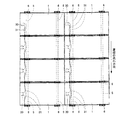
図2に示すように、屋根に取り付けられた支持金具を介して架台5が屋根上に所定の間隔をあけて固定される。本実施形態においては、屋根の流れ方向に対して平行方向に所定の間隔を有して架台5を屋根上に固定し、これに直交する方向に太陽電池モジュール1の長辺側が位置するように配置している。即ち、太陽電池モジュール1を屋根の流れ方向に対して横向きに配置し、太陽電池モジュール1の長辺側で固定している。これは、傾斜屋根葺き材(瓦等)により、太陽電池モジュール1の取り付けピッチが安定しないことを太陽電池モジュール1の長辺側で吸収するためである。   As shown in FIG. 2, the gantry 5 is fixed on the roof with a predetermined interval via a support fitting attached to the roof. In the present embodiment, the gantry 5 is fixed on the roof with a predetermined interval in a direction parallel to the flow direction of the roof, and the long side of the solar cell module 1 is positioned in a direction perpendicular to the gantry 5. It is arranged. That is, the solar cell module 1 is disposed sideways with respect to the flow direction of the roof, and is fixed on the long side of the solar cell module 1. This is because the slanted roofing material (tile or the like) absorbs that the mounting pitch of the solar cell module 1 is not stable on the long side of the solar cell module 1.

同様に太陽電池モジュール1を屋根の流れ方向に対して縦置きにする場合には、傾斜屋根葺き材(瓦等)により、太陽電池モジュール1の取り付けピッチが安定しないので、屋根の流れ方向に対して垂直方向に所定の間隔を有して架台5を屋根上に固定し、太陽電池モジュール1の長辺方向を桁方向に流して、太陽電池モジュール1の長辺側で固定する。   Similarly, when the solar cell module 1 is placed vertically with respect to the flow direction of the roof, the mounting pitch of the solar cell module 1 is not stable due to the sloped roofing material (tile, etc.). Then, the gantry 5 is fixed on the roof with a predetermined interval in the vertical direction, the long side direction of the solar cell module 1 is passed in the girder direction, and fixed on the long side side of the solar cell module 1.

この架台5にスペーサ6をボルト82とナット83からなる固定手段8で固定する。このスペーサ6の載置面61上にフレーム20の底部を載せ、固定部材7をフレーム20の支持部28に固定部材7の足部が掛かるように配置する。そして、固定部材7を締め付け、フレーム20を架台5方向に押しつけ、スペーサ6上に太陽電池モジュール1が固定される。   The spacer 6 is fixed to the gantry 5 with fixing means 8 including bolts 82 and nuts 83. The bottom portion of the frame 20 is placed on the mounting surface 61 of the spacer 6, and the fixing member 7 is disposed so that the foot portion of the fixing member 7 is hooked on the support portion 28 of the frame 20. Then, the fixing member 7 is tightened, the frame 20 is pressed in the direction of the gantry 5, and the solar cell module 1 is fixed on the spacer 6.

このように、架台5にスペーサ6を介して太陽電池モジュール1を固定することにより、太陽電池モジュール1が撓んだ際にも太陽電池モジュール1の裏面に配設したケーブル31が架台5との間に挟まれないようにしてケーブル31が破損することを抑制するように構成することができる。   Thus, by fixing the solar cell module 1 to the gantry 5 via the spacer 6, the cable 31 disposed on the back surface of the solar cell module 1 is connected to the gantry 5 even when the solar cell module 1 is bent. The cable 31 can be configured to be prevented from being damaged so as not to be sandwiched therebetween.

さらに図2に示すように、このスペーサ6は、長辺側のフレーム20の延在方向に架台5の幅よりも長い載置面61を有し、フレーム20から架台5にかかる圧力を分散することができる。この結果、耐荷重が同じフレーム20であってもより大きな圧力に耐えることができ、太陽光発電装置に雪の多い地域で想定される荷重に対して必要とされる強度を持たせることができる。   Further, as shown in FIG. 2, the spacer 6 has a mounting surface 61 longer than the width of the gantry 5 in the extending direction of the frame 20 on the long side, and disperses the pressure applied from the frame 20 to the gantry 5. be able to. As a result, even if the load resistance is the same frame 20, it can withstand a greater pressure, and the photovoltaic power generation apparatus can have the strength required for the load assumed in a snowy region. .

また、上記したように、スペーサ6が太陽電池モジュール1または架台5に対して回転すると、固定部材7とスペーサ6とがわずかな面積しか接触していない状態で固定されるおそれがある。そこで、本実施形態においては、スペーサ6が太陽電池モジュール1に対して回り止め機能を備えることにより、取り付け作業が容易にするとともに、太陽電池モジュール1をケーブルの破損を防止できる適切な取り付け位置に容易に配置できるようにしてより確実に太陽電池モジュール1を架台5に固定した太陽光発電装置を提供するものである。以下、各部材と共に詳細に説明する。   Further, as described above, when the spacer 6 rotates with respect to the solar cell module 1 or the gantry 5, there is a possibility that the fixing member 7 and the spacer 6 are fixed in a state where only a small area is in contact. Therefore, in the present embodiment, the spacer 6 has a function of preventing rotation with respect to the solar cell module 1, thereby facilitating the installation work and at a suitable installation position that can prevent the cable from being damaged. A solar power generation apparatus in which the solar cell module 1 is fixed to the gantry 5 more securely by being easily arranged is provided. Hereinafter, it explains in detail with each member.

図3及び図4は、本発明に用いられる架台5の一例を示し、図3は側面図、図4は横断面図である。架台5は、例えば、アルミニウム、鉄、或いはステンレス鋼等で形成され、押し出し成形、引き出し成形等で作成される。本実施形態においては、アルミニウムを押し出し成形で形成してフレーム20が作成される。架台5のスペーサ6の取り付け面51には、スペーサ6を固定するためのボルトが収容される係合部52が設けられている。この係合部52に後述するように、ボルト、ナットを用いてスペーサ6が取り付けられる。架台5は後述するように屋根に固定された支持金具に取付金具を用いて固定され、本実施形態においては、屋根の流れ方向に対して平行方向に所定の間隔を有して固定される。   3 and 4 show an example of the gantry 5 used in the present invention, FIG. 3 is a side view, and FIG. 4 is a cross-sectional view. The gantry 5 is made of, for example, aluminum, iron, stainless steel, or the like, and is made by extrusion molding, drawer molding, or the like. In the present embodiment, the frame 20 is formed by forming aluminum by extrusion molding. On the attachment surface 51 of the spacer 6 of the gantry 5, an engaging portion 52 that accommodates a bolt for fixing the spacer 6 is provided. As will be described later, the spacer 6 is attached to the engaging portion 52 using bolts and nuts. As will be described later, the gantry 5 is fixed to a support bracket fixed to the roof by using a mounting bracket. In the present embodiment, the gantry 5 is fixed at a predetermined interval in a direction parallel to the flow direction of the roof.

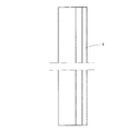
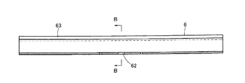
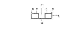
図5から図7は、本発明の第1の実施形態にかかるスペーサを示し、図5は平面図、図6は図5のA−A線断面図、図7は図6のB−B線断面図である。スペーサ6は、例えば、アルミニウム、鉄、或いはステンレス鋼等で形成され、押し出し成形、引き出し成形等で作成される。本実施形態においては、アルミニウムを押し出し成形で形成してフレーム20が作成される。スペーサ6は、架台5の幅よりも長い載置面61を有する。そして、載置面61の外周側にフレーム20側へ突出する凸部としてのリブ部63が形成されている。後述するように、スペーサ6が回ると、このリブ部63がフレーム20にあたり、それ以上の回転が阻止される。   5 to 7 show a spacer according to the first embodiment of the present invention, FIG. 5 is a plan view, FIG. 6 is a cross-sectional view taken along line AA in FIG. 5, and FIG. 7 is a line BB in FIG. It is sectional drawing. The spacer 6 is made of, for example, aluminum, iron, or stainless steel, and is made by extrusion molding, drawer molding, or the like. In the present embodiment, the frame 20 is formed by forming aluminum by extrusion molding. The spacer 6 has a placement surface 61 that is longer than the width of the gantry 5. And the rib part 63 as a convex part which protrudes to the flame | frame 20 side is formed in the outer peripheral side of the mounting surface 61. As shown in FIG. As will be described later, when the spacer 6 rotates, the rib portion 63 hits the frame 20 to prevent further rotation.

スペーサ6の中央部には、凹部67が形成され、この凹部67の中央部には、架台5の係合部52に収容されたボルトが通される穴62が設けられている。   A concave portion 67 is formed in the central portion of the spacer 6, and a hole 62 through which a bolt accommodated in the engaging portion 52 of the gantry 5 is provided is provided in the central portion of the concave portion 67.

図8から図10は、本発明の実施形態にかかる固定部材を示し、図8は平面図、図9は図8のB−B線断面図、図10は図8のA−A線断面図である。固定部材7は、断面がコの字型の鋼材で形成され、上面部には、架台5に取り付けられ、スペーサ6を通したボルト82を通すための穴71を有する。また、固定部材7の足部72は、図10に示すように、フレーム20の支持部28をスペーサ6側に押さえつけるときにしっかり固定できるように円弧が切り取られた形状に形成される。   8 to 10 show a fixing member according to an embodiment of the present invention, FIG. 8 is a plan view, FIG. 9 is a sectional view taken along line BB in FIG. 8, and FIG. 10 is a sectional view taken along line AA in FIG. It is. The fixing member 7 is formed of a steel material having a U-shaped cross section, and has a hole 71 that is attached to the gantry 5 and allows a bolt 82 through the spacer 6 to pass through on the upper surface portion. Further, as shown in FIG. 10, the foot portion 72 of the fixing member 7 is formed in a shape in which an arc is cut so that it can be firmly fixed when the support portion 28 of the frame 20 is pressed against the spacer 6 side.

次に、図11から図17を参照して、この第1の実施形態にかかるスペーサを用いて屋根上に固定された架台に太陽電池モジュール1を固定した太陽光発電装置について説明する。   Next, with reference to FIG. 11 to FIG. 17, a solar power generation apparatus in which the solar cell module 1 is fixed to a gantry fixed on the roof using the spacer according to the first embodiment will be described.

図2に示すように、屋根に取り付けられた支持金具を介して架台5が屋根上に所定の間隔をあけて固定される。本実施形態においては、屋根の流れ方向に対して平行方向に所定の間隔を有して架台5を屋根上に固定している。図11及び図13は、屋根の軒と平行の方向から見た一部を断面にした正面図、図12及び図14は、屋根の流れ方向から見た一部を断面にした側面図である。   As shown in FIG. 2, the gantry 5 is fixed on the roof with a predetermined interval via a support fitting attached to the roof. In the present embodiment, the gantry 5 is fixed on the roof with a predetermined interval in a direction parallel to the flow direction of the roof. 11 and 13 are front views in which a part is seen from a direction parallel to the eaves of the roof, and FIGS. 12 and 14 are side views in which a part is seen from the flow direction of the roof. .

図11及び図13に示すように、屋根上の屋根瓦300上に支持金具301が固定されている。支持金具301の屋根への固定は種々の方法があるが、アンカー方式や差込方式等屋根の形状に応じて最適な方法により、屋根瓦300上に確実に支持金具301が固定される。この支持金具301に取付金具302及びビス303を用いて架台5が固定される。   As shown in FIG.11 and FIG.13, the support metal fitting 301 is being fixed on the roof tile 300 on a roof. There are various methods for fixing the support bracket 301 to the roof, but the support bracket 301 is securely fixed on the roof tile 300 by an optimum method according to the shape of the roof such as an anchor method or an insertion method. The mount 5 is fixed to the support bracket 301 using the mounting bracket 302 and the screw 303.

架台5の係合部52にボルト82を取り付ける。そして、スペーサ6の長手方向を架台5の長手方向に合わせ、スペーサ6の穴62にボルト82が通される。ボルト82にワッシャー84及びナット83を取り付け、ナット83を締め付けることにより、架台5にスペーサ6が固定される。   A bolt 82 is attached to the engaging portion 52 of the gantry 5. Then, the longitudinal direction of the spacer 6 is aligned with the longitudinal direction of the gantry 5, and the bolt 82 is passed through the hole 62 of the spacer 6. The spacer 6 is fixed to the gantry 5 by attaching a washer 84 and a nut 83 to the bolt 82 and tightening the nut 83.

架台5に固定したスペーサ6の載置面61に太陽電池モジュール1のフレーム20の底部が配置される。そして、スペーサ6を貫通したボルト82に固定部材7の穴72が通される。フレーム20の支持部28に固定部材7の足部72が掛かるように配置し、ワッシャー84及びナット81をボルト82に取り付け、ナット81を締め付ける。ナット81を締め付けることにより、フレーム20の支持部28を固定部材7によりスペーサ6側に押さえつけ、太陽電池モジュール1がスペーサ6を介して架台5に固定される。   The bottom portion of the frame 20 of the solar cell module 1 is disposed on the mounting surface 61 of the spacer 6 fixed to the gantry 5. Then, the hole 72 of the fixing member 7 is passed through the bolt 82 penetrating the spacer 6. The support part 28 of the frame 20 is disposed so that the foot part 72 of the fixing member 7 is hooked, the washer 84 and the nut 81 are attached to the bolt 82, and the nut 81 is tightened. By tightening the nut 81, the support portion 28 of the frame 20 is pressed against the spacer 6 side by the fixing member 7, and the solar cell module 1 is fixed to the gantry 5 via the spacer 6.

このように、架台5にスペーサ6を介して太陽電池モジュール1を固定することにより、太陽電池モジュール1が撓んだ際にも太陽電池モジュール1の裏面に配設したケーブル31が架台5との間に挟まれないようにしてケーブル31が破損することを抑制するように構成することができる。   Thus, by fixing the solar cell module 1 to the gantry 5 via the spacer 6, the cable 31 disposed on the back surface of the solar cell module 1 is connected to the gantry 5 even when the solar cell module 1 is bent. The cable 31 can be configured to be prevented from being damaged so as not to be sandwiched therebetween.

さらに、このスペーサ6は、長辺側のフレーム20の延在方向に、架台5の幅よりも長い載置面61が形成されており、フレーム20からかかる圧力を分散することができる。この結果、耐荷重が同じフレーム20であってもより大きな圧力に耐えることができ、太陽光発電装置に雪の多い地域で想定される荷重に対して必要とされる強度を持たせることができる。   Further, the spacer 6 is formed with a mounting surface 61 longer than the width of the gantry 5 in the extending direction of the frame 20 on the long side, so that the pressure applied from the frame 20 can be dispersed. As a result, even if the load resistance is the same frame 20, it can withstand a greater pressure, and the photovoltaic power generation apparatus can have the strength required for the load assumed in a snowy region. .

図12、図14及び図15に示すように、太陽電池モジュール1をスペーサ6に固定部材7を用いて取り付けると、スペーサ6のリブ部63は、フレーム20の底部の近傍に位置することになる。スペーサ6が回わろうとすると、リブ部63がフレーム60の底部にあたり、それ以上の回転が阻止される。   As shown in FIGS. 12, 14, and 15, when the solar cell module 1 is attached to the spacer 6 using the fixing member 7, the rib portion 63 of the spacer 6 is positioned in the vicinity of the bottom portion of the frame 20. . When the spacer 6 tries to rotate, the rib portion 63 hits the bottom of the frame 60 and further rotation is prevented.

図16及び図17に示すように、片側にしか太陽電池モジュール1が取り付けられない太陽光発電装置の端の部分は、固定部材7の足部72が直接スペーサ6に接触するようにして固定することになる。   As shown in FIGS. 16 and 17, the end portion of the photovoltaic power generation apparatus to which the solar cell module 1 can be attached only on one side is fixed so that the foot 72 of the fixing member 7 is in direct contact with the spacer 6. It will be.

このとき、組み立てのバラツキなどにより、スペーサ6が回ろうとしても、図18で示すように、リブ部63がフレーム60にあたり、それ以上の回転が阻止される。固定部材7のボルト82が通される穴71とこの穴71に通されるボルト82には、組み立ての容易さからある程度の遊びがあっても、スペーサ7の回転が阻止され、架台5に対して略平行な状態にスペーサ6が保たれるので、固定部材7とスペーサ6を適切な取り付け位置に容易に配置することができる。   At this time, even if the spacer 6 tries to turn due to assembly variations or the like, as shown in FIG. 18, the rib portion 63 hits the frame 60 and further rotation is prevented. Even if there is some play in the hole 71 through which the bolt 82 of the fixing member 7 is passed and the bolt 82 passed through the hole 71, even if there is some play, the rotation of the spacer 7 is prevented. Since the spacer 6 is maintained in a substantially parallel state, the fixing member 7 and the spacer 6 can be easily arranged at an appropriate attachment position.

図18から図20は、本発明の第2の実施形態にかかるスペーサを示し、図18は平面図、図19はB−B線断面図、図20はA−A線断面図である。スペーサ6aは、例えば、アルミニウム、鉄、或いはステンレス鋼等で形成される。本実施形態においては、アルミニウムで形成している。   18 to 20 show a spacer according to a second embodiment of the present invention. FIG. 18 is a plan view, FIG. 19 is a sectional view taken along line BB, and FIG. 20 is a sectional view taken along line AA. The spacer 6a is made of, for example, aluminum, iron, stainless steel, or the like. In this embodiment, it is made of aluminum.

この第2の実施形態のスペーサ6aも長辺側のフレーム20の延在方向に、架台5の幅よりも長い載置面61aが形成されている。そして、載置面61の外周側にフレーム20側に突出する凸部としてのリブ部63aが形成されている。後述するように、スペーサ6aが回ると、このリブ部63aがフレーム20にあたり、それ以上の回転が阻止される。   In the spacer 6a of the second embodiment, a mounting surface 61a longer than the width of the gantry 5 is formed in the extending direction of the frame 20 on the long side. And the rib part 63a as a convex part which protrudes in the flame | frame 20 side is formed in the outer peripheral side of the mounting surface 61. As shown in FIG. As will be described later, when the spacer 6a rotates, the rib portion 63a hits the frame 20, and further rotation is prevented.

スペーサ6aの中央部には、架台5の係合部52に収容されたボルトが通される穴62aが設けられている。そして、この穴62aから外側にフレーム20側に突出する凸部65aが設けられ、この凸部65aにフレーム20の支持部28の立ち上がり部があたり、フレーム20の取り付け時に太陽電池モジュール1が適切な取り付け位置に配置されるように構成されている。   A hole 62a through which a bolt accommodated in the engaging portion 52 of the gantry 5 is passed is provided at the center of the spacer 6a. And the convex part 65a which protrudes to the flame | frame 20 side is provided in the outer side from this hole 62a, the rising part of the support part 28 of the flame | frame 20 hits this convex part 65a, and the solar cell module 1 is suitable at the time of attachment of the flame | frame 20. It is comprised so that it may be arrange | positioned in an attachment position.

さらに、このスペーサ6aには、端子ボックス30から引き出されたケーブル31を収容し、接続先へ導く案内溝64aが設けられている。この案内溝64aにケーブル31を収容することでケーブル31が他の部材により挟み込まれることが確実に防止され、ケーブル31の破損を防止する。   Furthermore, the spacer 6a is provided with a guide groove 64a that accommodates the cable 31 drawn from the terminal box 30 and guides it to the connection destination. By accommodating the cable 31 in the guide groove 64a, the cable 31 is reliably prevented from being sandwiched between other members, and the cable 31 is prevented from being damaged.

次に、図21から図24を参照して、この第2の実施形態にかかるスペーサを用いて屋根上に固定された架台に太陽電池モジュール1を固定した太陽光発電装置について説明する。   Next, with reference to FIGS. 21 to 24, a solar power generation apparatus in which the solar cell module 1 is fixed to a gantry fixed on the roof using the spacer according to the second embodiment will be described.

図2に示すように、屋根に取り付けられた支持金具を介して架台5が屋根上に所定の間隔をあけて固定される。本実施形態においては、屋根の流れ方向に対して平行方向に所定の間隔を有して架台5を屋根上に固定している。   As shown in FIG. 2, the gantry 5 is fixed on the roof with a predetermined interval via a support fitting attached to the roof. In the present embodiment, the gantry 5 is fixed on the roof with a predetermined interval in a direction parallel to the flow direction of the roof.

図21及び図23に示すように、屋根上の屋根瓦300上に支持金具301が固定されている。この支持金具301に取付金具302及びビス303を用いて架台5が固定される。   As shown in FIGS. 21 and 23, a support fitting 301 is fixed on a roof tile 300 on the roof. The mount 5 is fixed to the support bracket 301 using the mounting bracket 302 and the screw 303.

架台5の係合部52にボルト82を取り付ける。そして、スペーサ6aの長手方向を架台5の長手方向に合わせ、スペーサ6aの穴62aにボルト82が通される。ボルト82にワッシャー84及びナット83を取り付け、ナット83を締め付けることにより、架台5にスペーサ6aが固定される。   A bolt 82 is attached to the engaging portion 52 of the gantry 5. Then, the longitudinal direction of the spacer 6a is aligned with the longitudinal direction of the gantry 5, and the bolt 82 is passed through the hole 62a of the spacer 6a. A spacer 6 a is fixed to the gantry 5 by attaching a washer 84 and a nut 83 to the bolt 82 and tightening the nut 83.

架台5に固定したスペーサ6aの載置面61aに太陽電池モジュール1のフレーム20の底部が配置される。このとき、図22及び図24に示すように、凸部65aにフレーム20の支持部28の立ち上がり部が当たるようにする。凸部65aにフレーム20の支持部28の立ち上がり部をあたるようにすることにより、太陽電池モジュール1をスペーサ6aの適切な取り付け位置に容易に配置することができる。そして、スペーサ6aを貫通したボルト82に固定部材7の穴72が通される。フレーム20の支持部28に固定部材7の足部72が掛かるように配置し、ワッシャー84及びナット81をボルト82に取り付け、ナット81を締め付ける。ナット81を締め付けることにより、フレーム20の支持部28を固定部材7によりスペーサ6a側に押さえつけ、太陽電池モジュール1がスペーサ6aを介して架台5に固定される。また、端子ボックス30から引き出されたケーブル31は、案内溝64a内に収容され、他の太陽電池モジュール1の裏面へ導かれる。   The bottom portion of the frame 20 of the solar cell module 1 is disposed on the mounting surface 61 a of the spacer 6 a fixed to the gantry 5. At this time, as shown in FIGS. 22 and 24, the rising portion of the support portion 28 of the frame 20 is made to contact the convex portion 65a. The solar cell module 1 can be easily disposed at an appropriate mounting position of the spacer 6a by making the raised portion of the support portion 28 of the frame 20 hit the convex portion 65a. Then, the hole 72 of the fixing member 7 is passed through the bolt 82 penetrating the spacer 6a. The support part 28 of the frame 20 is disposed so that the foot part 72 of the fixing member 7 is hooked, the washer 84 and the nut 81 are attached to the bolt 82, and the nut 81 is tightened. By tightening the nut 81, the support portion 28 of the frame 20 is pressed against the spacer 6a side by the fixing member 7, and the solar cell module 1 is fixed to the gantry 5 via the spacer 6a. Further, the cable 31 drawn from the terminal box 30 is accommodated in the guide groove 64 a and guided to the back surface of the other solar cell module 1.

このように、太陽電池モジュールを架台5に固定する際に、スペーサ6aの案内溝64a内にケーブル31を収容することにより、太陽電池モジュール1が撓んだ際にも太陽電池モジュール1の裏面に配設したケーブル31が架台5との間に挟まれないようにしてケーブル31が破損することを抑制することができる。   As described above, when the solar cell module is fixed to the gantry 5, the cable 31 is accommodated in the guide groove 64 a of the spacer 6 a so that the solar cell module 1 can be attached to the back surface of the solar cell module 1 even when the solar cell module 1 is bent. It is possible to prevent the cable 31 from being damaged by preventing the arranged cable 31 from being sandwiched between the mount 5 and the cable 31.

また、このスペーサ6aは、長辺側のフレーム20Aの延在方向に、架台5の幅よりも長い載置面61aを有し、フレーム20からかかる圧力を分散することができる。この結果、耐荷重が同じフレーム20であっても大きな圧力に耐えることができ、太陽光発電装置に雪の多い地域で想定される荷重に対して必要とされる強度を持たせることができる。   The spacer 6a has a mounting surface 61a longer than the width of the gantry 5 in the extending direction of the frame 20A on the long side, and can disperse the pressure applied from the frame 20. As a result, even the frame 20 having the same load resistance can withstand a large pressure, and the photovoltaic power generation apparatus can have a strength required for a load assumed in a snowy region.

図21及び図24に示すように、太陽電池モジュール1をスペーサ6aに固定部材7を用いて取り付けると、スペーサ6aのリブ部63aは、フレーム20の底部の近傍に位置することになる。スペーサ6aが回わろうとすると、リブ部63aがフレーム60にあたり、それ以上の回転が阻止される。   As shown in FIGS. 21 and 24, when the solar cell module 1 is attached to the spacer 6 a using the fixing member 7, the rib portion 63 a of the spacer 6 a is located in the vicinity of the bottom portion of the frame 20. When the spacer 6a tries to turn, the rib portion 63a hits the frame 60, and further rotation is prevented.

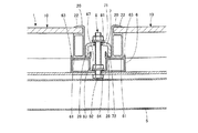
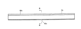
図25から図27は、本発明の第3の実施形態にかかるスペーサを示し、図25は平面図、図26は図25のA−A線断面図、図27は図26のB−B線断面図である。スペーサ6cは、例えば、アルミニウム、鉄、或いはステンレス鋼等で形成される。本実施形態においては、スペーサ6cをアルミニウムで形成している。   25 to 27 show a spacer according to a third embodiment of the present invention. FIG. 25 is a plan view, FIG. 26 is a sectional view taken along line AA in FIG. 25, and FIG. It is sectional drawing. The spacer 6c is made of, for example, aluminum, iron, stainless steel, or the like. In the present embodiment, the spacer 6c is made of aluminum.

この第3の実施形態のスペーサ6cも長辺側のフレーム20の延在方向に、架台5の幅よりも長い載置面61cを有している。スペーサ6cの中央部には、凹部67cが設けられる。この凹部67cの中央部に、架台5の係合部52に収容されたボルト82が通される穴62cが設けられている。そして、凹部67cの外側にフレーム20側に突出する凸部としてのリブ部66cが設けられている。このリブ部66cがフレーム20にあたることにより、回り止め機構として作用し、スペーサ6cの回転が阻止される。   The spacer 6c of the third embodiment also has a placement surface 61c that is longer than the width of the gantry 5 in the extending direction of the frame 20 on the long side. A recess 67c is provided at the center of the spacer 6c. A hole 62c through which the bolt 82 accommodated in the engaging portion 52 of the gantry 5 is passed is provided at the center of the recess 67c. And the rib part 66c as a convex part which protrudes in the flame | frame 20 side is provided in the outer side of the recessed part 67c. When the rib portion 66c hits the frame 20, it acts as a detent mechanism and the spacer 6c is prevented from rotating.

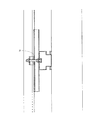
次に、図28から図30を参照して、この第3の実施形態にかかるスペーサを用いて屋根上に固定された架台に太陽電池モジュール1を固定した太陽光発電装置について説明する。   Next, with reference to FIG. 28 to FIG. 30, a solar power generation apparatus in which the solar cell module 1 is fixed to a gantry fixed on the roof using the spacer according to the third embodiment will be described.

図2に示すように、屋根に取り付けられた支持金具を介して架台5が屋根上に所定の間隔をあけて固定される。本実施形態においては、屋根の流れ方向に対して平行方向に所定の間隔を有して架台5を屋根上に固定している。   As shown in FIG. 2, the gantry 5 is fixed on the roof with a predetermined interval via a support fitting attached to the roof. In the present embodiment, the gantry 5 is fixed on the roof with a predetermined interval in a direction parallel to the flow direction of the roof.

架台5の係合部52にボルト82を取り付ける。そして、スペーサ6cの長手方向を架台5の長手方向に合わせ、スペーサ6cの穴62cにボルト82が通される。ボルト82にワッシャー84及びナット83を取り付け、ナット83を締め付けることにより、架台5にスペーサ6cが固定される。   A bolt 82 is attached to the engaging portion 52 of the gantry 5. The longitudinal direction of the spacer 6c is aligned with the longitudinal direction of the gantry 5, and the bolt 82 is passed through the hole 62c of the spacer 6c. A spacer 6 c is fixed to the gantry 5 by attaching a washer 84 and a nut 83 to the bolt 82 and tightening the nut 83.

架台5に固定したスペーサ6cの載置面61cに太陽電池モジュール1のフレーム20の底部が配置される。このとき、図28及び図30に示すように、フレーム20にリブ部66cがあたるようにすることにより、太陽電池モジュール1をスペーサ6cの適切な取り付け位置に容易に配置することができる。そして、スペーサ6cを貫通したボルト82に固定部材7の穴72が通される。フレーム20の支持部28に固定部材7の足部72が入るように配置し、ワッシャー84及びナット81をボルト82に取り付け、ナット81を締め付ける。ナット81を締め付けることにより、フレーム20の支持部28を介してフレーム20が固定部材7によりスペーサ6c側に押さえられ、太陽電池モジュール1がスペーサ6cを介して架台5に固定される。   The bottom portion of the frame 20 of the solar cell module 1 is disposed on the mounting surface 61 c of the spacer 6 c fixed to the gantry 5. At this time, as shown in FIG. 28 and FIG. 30, the solar cell module 1 can be easily disposed at an appropriate mounting position of the spacer 6 c by making the rib portion 66 c hit the frame 20. Then, the hole 72 of the fixing member 7 is passed through the bolt 82 penetrating the spacer 6c. It arrange | positions so that the leg part 72 of the fixing member 7 may enter into the support part 28 of the flame | frame 20, A washer 84 and the nut 81 are attached to the volt | bolt 82, and the nut 81 is tightened. By tightening the nut 81, the frame 20 is pressed to the spacer 6c side by the fixing member 7 through the support portion 28 of the frame 20, and the solar cell module 1 is fixed to the gantry 5 through the spacer 6c.

このように、架台5にスペーサ6cを介して太陽電池モジュール1を固定することにより、太陽電池モジュール1が撓んだ際にも太陽電池モジュール1の裏面に配設したケーブル31が架台5との間に挟まれないようにしてケーブル31が破損することを抑制するように構成することができる。   In this way, by fixing the solar cell module 1 to the gantry 5 via the spacer 6 c, the cable 31 disposed on the back surface of the solar cell module 1 is connected to the gantry 5 even when the solar cell module 1 is bent. The cable 31 can be configured to be prevented from being damaged so as not to be sandwiched therebetween.

また、このスペーサ6cは、長辺側のフレーム20の延在方向に、架台5の幅よりも長い載置面61が形成されており、フレーム20から架台5にかかる圧力を分散することができる。この結果、耐荷重が同じフレーム20であっても大きな圧力に耐えることができ、太陽光発電装置に雪の多い地域で想定される荷重に対して必要とされる強度を持たせることができる。   The spacer 6c has a mounting surface 61 that is longer than the width of the gantry 5 in the extending direction of the frame 20 on the long side, and can distribute the pressure applied to the gantry 5 from the frame 20. . As a result, even the frame 20 having the same load resistance can withstand a large pressure, and the photovoltaic power generation apparatus can have a strength required for a load assumed in a snowy region.

図28及び図30に示すように、太陽電池モジュール1をスペーサ6cに固定部材7を用いて取り付けると、スペーサ6のリブ部66cがフレーム20にあたることにより、回り止め機構として作用し、スペーサ6aの回転が阻止される。   As shown in FIGS. 28 and 30, when the solar cell module 1 is attached to the spacer 6 c using the fixing member 7, the rib portion 66 c of the spacer 6 hits the frame 20, thereby acting as a detent mechanism, and the spacer 6 a Rotation is prevented.

図31及び図30は、本発明の第4の実施形態にかかるスペーサを示し、図31は平面図、図32は横断面図である。スペーサ6dは、例えば、アルミニウム、鉄、或いはステンレス鋼等で形成される。本実施形態においては、アルミニウムで形成している。   31 and 30 show a spacer according to a fourth embodiment of the present invention, FIG. 31 is a plan view, and FIG. 32 is a cross-sectional view. The spacer 6d is made of, for example, aluminum, iron, stainless steel, or the like. In this embodiment, it is made of aluminum.

この第4の実施形態のスペーサ6dは架台5の幅よりも長い直径を有する円盤状の載置面61dが形成されている。そして、載置面61dは円盤状に形成されているので、スペーサ6dが回転してもフレーム20並びに固定部材7に対する位置関係は変わらず、固定部材7等が外れるおそれはない。   The spacer 6d of the fourth embodiment is formed with a disc-like mounting surface 61d having a diameter longer than the width of the gantry 5. Since the mounting surface 61d is formed in a disc shape, the positional relationship with respect to the frame 20 and the fixing member 7 does not change even when the spacer 6d rotates, and there is no possibility that the fixing member 7 or the like will come off.

スペーサ6dの中央部には、架台5の係合部52に収容されたボルトが通される穴62dが設けられている。そして、この穴62dから外側に凸部65dが設けられ、この凸部65dにフレーム20の支持部28の立ち上がり部当接し、フレーム20の取り付け時の位置決めとなるように構成されている。   At the center of the spacer 6d, a hole 62d through which a bolt accommodated in the engaging portion 52 of the gantry 5 is passed is provided. A convex portion 65d is provided outside the hole 62d, and the rising portion of the support portion 28 of the frame 20 is brought into contact with the convex portion 65d so as to be positioned when the frame 20 is attached.

次に、図33及び図34を参照して、この第4の実施形態にかかるスペーサを用いて屋根上に固定された架台に太陽電池モジュール1を固定した太陽光発電装置につき説明する。   Next, with reference to FIG.33 and FIG.34, the solar power generation device which fixed the solar cell module 1 to the mount fixed on the roof using the spacer concerning this 4th Embodiment is demonstrated.

図2に示すように、屋根に取り付けられた支持金具を介して架台5が屋根上に所定の間隔をあけて固定される。本実施形態においては、屋根の流れ方向に対して平行方向に所定の間隔を有して架台5を屋根上に固定している。   As shown in FIG. 2, the gantry 5 is fixed on the roof with a predetermined interval via a support fitting attached to the roof. In the present embodiment, the gantry 5 is fixed on the roof with a predetermined interval in a direction parallel to the flow direction of the roof.

架台5の係合部52にボルト82を取り付ける。そして、スペーサ6dの穴62dにボルト82が通される。ボルト82にワッシャー84及びナット83を取り付け、ナット83を締め付けることにより、架台5にスペーサ6dが固定される。   A bolt 82 is attached to the engaging portion 52 of the gantry 5. Then, the bolt 82 is passed through the hole 62d of the spacer 6d. A spacer 6 d is fixed to the gantry 5 by attaching a washer 84 and a nut 83 to the bolt 82 and tightening the nut 83.

架台5に固定したスペーサ6dの円盤状の載置面61dに太陽電池モジュール1のフレーム20の底部が配置される。このとき、図33に示すように、凸部65dにフレーム20の支持部28の立ち上がり部が当たるように配置される。凸部65dにフレーム20の支持部28の立ち上がり部があたるようにすることにより、太陽電池モジュール1をスペーサ6dの適切な取り付け位置に容易に配置することができる。そして、スペーサ6dを貫通したボルト82に固定部材7の穴72が通される。フレーム20の支持部28と固定部材7の足部72が入るように配置し、ワッシャー84及びナット81をボルト82に取り付け、ナット81を締め付ける。ナット81を締め付けることにより、フレーム20の支持部28を固定部材7によりスペーサ6d側に押さえつけ、太陽電池モジュール1がスペーサ6dを介して架台5に固定される。   The bottom portion of the frame 20 of the solar cell module 1 is disposed on the disc-shaped mounting surface 61 d of the spacer 6 d fixed to the gantry 5. At this time, as shown in FIG. 33, it arrange | positions so that the standing part of the support part 28 of the flame | frame 20 may contact | project the convex part 65d. By making the raised portion of the support portion 28 of the frame 20 hit the convex portion 65d, the solar cell module 1 can be easily arranged at an appropriate mounting position of the spacer 6d. Then, the hole 72 of the fixing member 7 is passed through the bolt 82 penetrating the spacer 6d. The support portion 28 of the frame 20 and the foot portion 72 of the fixing member 7 are arranged so as to enter, the washer 84 and the nut 81 are attached to the bolt 82, and the nut 81 is tightened. By tightening the nut 81, the support portion 28 of the frame 20 is pressed against the spacer 6d side by the fixing member 7, and the solar cell module 1 is fixed to the gantry 5 via the spacer 6d.

このように、架台5にスペーサ6dを介して太陽電池モジュール1を固定することにより、太陽電池モジュール1が撓んだ際にも太陽電池モジュール1の裏面に配設したケーブル31が架台5との間に挟まれないようにしてケーブル31が破損することを抑制するように構成することができる。   Thus, by fixing the solar cell module 1 to the gantry 5 via the spacer 6d, the cable 31 disposed on the back surface of the solar cell module 1 is connected to the gantry 5 even when the solar cell module 1 is bent. The cable 31 can be configured to be prevented from being damaged so as not to be sandwiched therebetween.

また、このスペーサ6dは、架台5の幅よりも長い直径の円盤状載置面61dが形成されており、フレーム20から架台5にかかる圧力を分散することができる。この結果、耐荷重が同じフレーム20であっても大きな圧力に耐えることができ、太陽光発電装置に雪の多い地域で想定される荷重に対して必要とされる強度を持たせることができる。   Further, the spacer 6d is formed with a disk-shaped mounting surface 61d having a diameter longer than the width of the gantry 5 and can disperse the pressure applied from the frame 20 to the gantry 5. As a result, even the frame 20 having the same load resistance can withstand a large pressure, and the photovoltaic power generation apparatus can have a strength required for a load assumed in a snowy region.

図34に示すように、太陽電池モジュール1をスペーサ6aに固定部材7を用いて取り付けると、載置面61dは円盤状に形成されているので、スペーサ6dが回転してもフレーム20並びに固定部材7に対する位置関係は変わらず、固定部材7等が外れるおそれはない。   As shown in FIG. 34, when the solar cell module 1 is attached to the spacer 6a using the fixing member 7, the mounting surface 61d is formed in a disk shape, so that the frame 20 and the fixing member are also rotated even if the spacer 6d rotates. The positional relationship with respect to 7 does not change, and there is no possibility that the fixing member 7 or the like will come off.

なお、前記第1、第3、第4の実施形態においては、ケーブルを収容する案内溝を設けていないが、前記第2の実施形態と同様にケーブルを収容する案内溝を設けることは勿論可能である。   In the first, third, and fourth embodiments, the guide groove that accommodates the cable is not provided, but it is of course possible to provide the guide groove that accommodates the cable as in the second embodiment. It is.

今回開示された実施形態はすべての点で例示であって制限的なものではないと考えられるべきである。本発明の範囲は、上記した実施形態の説明ではなくて特許請求の範囲によって示され、特許請求の範囲と均等の意味および範囲内でのすべての変更が含まれることが意図される。   It should be thought that embodiment disclosed this time is an illustration and restrictive at no points. The scope of the present invention is shown not by the above description of the embodiments but by the scope of claims, and is intended to include all modifications within the meaning and scope equivalent to the scope of claims.

1 太陽電池モジュール
5 架台
6、6a、6c、6d スペーサ
61、61a、61c、61d 載置面
62 穴
63 リブ部
7 固定部材
8 固定手段 81、83 ナット
82 ボルト
10 太陽電池パネル
20 フレーム
28 支持部
DESCRIPTION OF SYMBOLS 1 Solar cell module 5 Base 6, 6a, 6c, 6d Spacer 61, 61a, 61c, 61d Mounting surface 62 Hole 63 Rib part 7 Fixing member 8 Fixing means 81, 83 Nut 82 Bolt 10 Solar cell panel 20 Frame 28 Support part

Claims (7)

所定の間隔をあけて固定され、取り付け面を備えた複数の架台と、
フレームを有する太陽電池モジュールと、
前記取り付け面と前記フレームの間に配置され、中央部に形成された凹部と前記凹部の両側に形成された載置面と、前記凹部に形成された穴と、を備える複数のスペーサと、
前記フレームを前記スペーサに押さえつけるための固定部材と、
前記スペーサ及び前記固定部材を通り、前記スペーサを前記架台上に固定するためのボルトと、
を備えた太陽光発電装置であって、
前記フレームは、前記固定部材と前記ボルトを用いて前記スペーサの前記載置面に押さえつけられることにより前記架台の前記取り付け面上に前記スペーサを介して固定され、
前記スペーサの前記載置面は凸部を有し、前記凸部により前記複数のスペーサと前記太陽電池モジュールとの取り付け位置を所定の位置に固定して回転を阻止することを特徴とする太陽光発電装置。
A plurality of mounts fixed at predetermined intervals and having mounting surfaces;
A solar cell module having a frame;
Disposed between the frame and the mounting surface, and a plurality of spacers having a recess formed in the central portion and both sides formed mounting surface of the recess, the hole formed in the recess, and
A fixing member for pressing the frame against the spacer;
A bolt for passing through the spacer and the fixing member and fixing the spacer on the mount;
A solar power generation device comprising:
The frame is fixed to the mounting surface of the mount via the spacer by being pressed against the mounting surface of the spacer using the fixing member and the bolt.
The placement surface of the spacer has a convex portion, and the convex portion prevents the rotation by fixing the mounting position of the plurality of spacers and the solar cell module at a predetermined position. Power generation device.
前記複数のスペーサは、前記凹部に通された前記ボルトと、ナットとを用いて前記架台に締め付け固定されている、請求項1に記載の太陽光発電装置。   2. The photovoltaic power generation apparatus according to claim 1, wherein the plurality of spacers are fastened and fixed to the mount using the bolts and nuts passed through the recesses. 前記複数のスペーサは、取り付けられる前記フレームの一辺の延在方向において、前記架台の前記取り付け面より長く、前記フレームの一辺の長さよりも短いことを特徴とする請求項1又は2に記載の太陽光発電装置。 Wherein the plurality of spacers, in the extending direction of one side of the mounted frame, wherein the frame the rather longer than the mounting surface of Claim 1 or 2, characterized in shorter Ikoto than the length of one side of the frame Solar power generator. 前記フレームには、底部から外方向に突出した支持部が設けられ、前記支持部には立ちあがり部を有することを特徴とする請求項1から請求項のいずれか1項に記載の太陽光発電装置。 Said frame includes a support portion protruding outward is provided at the bottom, photovoltaics according to claims 1, characterized in that it comprises a rising portion to the support portion in any one of claims 3 apparatus. 前記固定部材は、前記ボルトによって、前記フレームの前記支持部を前記スペーサの前記載置面に接触するように押し付けることによって、前記スペーサを前記架台の前記取り付け面に固定している、請求項4に記載の太陽光発電装置。  The said fixing member is fixing the said spacer to the said attachment surface of the said stand by pressing the said support part of the said frame with the said volt | bolt so that it may contact the said mounting surface of the said spacer. The solar power generation device described in 1. 前記複数のスペーサに前記フレームの前記支持部と当接する凸部を有することを特徴と
する請求項4又は5に記載の太陽光発電装置。
6. The solar power generation device according to claim 4, wherein the plurality of spacers have convex portions that come into contact with the support portion of the frame.
前記スペーサに前記太陽電池モジュールから電力を取り出すケーブルが収容される案内溝が設けられている請求項1から請求項6のいずれか1項に記載の太陽光発電装置。   The solar power generation device according to any one of claims 1 to 6, wherein a guide groove is provided in the spacer for accommodating a cable for taking out electric power from the solar cell module.
JP2011122606A 2011-05-31 2011-05-31 Solar power generation device and spacer for solar power generation device Active JP5948598B2 (en)

Priority Applications (1)

Application Number Priority Date Filing Date Title
JP2011122606A JP5948598B2 (en) 2011-05-31 2011-05-31 Solar power generation device and spacer for solar power generation device

Applications Claiming Priority (1)

Application Number Priority Date Filing Date Title
JP2011122606A JP5948598B2 (en) 2011-05-31 2011-05-31 Solar power generation device and spacer for solar power generation device

Related Child Applications (1)

Application Number Title Priority Date Filing Date
JP2016055528A Division JP6343810B2 (en) 2016-03-18 2016-03-18 Solar power generation device and spacer for solar power generation device

Publications (3)

Publication Number Publication Date
JP2012251304A JP2012251304A (en) 2012-12-20
JP2012251304A5 JP2012251304A5 (en) 2014-12-25
JP5948598B2 true JP5948598B2 (en) 2016-07-06

Family

ID=47524361

Family Applications (1)

Application Number Title Priority Date Filing Date
JP2011122606A Active JP5948598B2 (en) 2011-05-31 2011-05-31 Solar power generation device and spacer for solar power generation device

Country Status (1)

Country Link
JP (1) JP5948598B2 (en)

Families Citing this family (4)

* Cited by examiner, † Cited by third party
Publication number Priority date Publication date Assignee Title
WO2016024311A1 (en) * 2014-08-11 2016-02-18 株式会社ジャパンエネルギーグループ Composite module structure
JP6700976B2 (en) * 2015-05-28 2020-05-27 京セラ株式会社 Solar cell module and solar cell device
JP6587597B2 (en) * 2016-11-10 2019-10-09 三菱電機株式会社 Photovoltaic power generation system and fixing member
KR102391648B1 (en) * 2021-10-27 2022-04-28 주식회사 엔브이티 Aircraft noise block and noise reduction louver system capable of solar power generation

Family Cites Families (7)

* Cited by examiner, † Cited by third party
Publication number Priority date Publication date Assignee Title
JP3503363B2 (en) * 1996-10-16 2004-03-02 三菱電機株式会社 Panel structure fixing device
JP3810958B2 (en) * 1999-08-25 2006-08-16 株式会社カネカ Solar cell module fixing device and solar cell power generator
JP2004060358A (en) * 2002-07-31 2004-02-26 Kyocera Corp Fixing device for roof and structure for using solar energy using the same
US7856769B2 (en) * 2004-02-13 2010-12-28 Pvt Solar, Inc. Rack assembly for mounting solar modules
JP4679435B2 (en) * 2006-05-22 2011-04-27 株式会社屋根技術研究所 Wiring storage structure for installations on the roof
US8511008B2 (en) * 2008-08-29 2013-08-20 Sharp Kabushiki Kaisha Solar cell module attachment structure and solar cell apparatus
JP4562793B2 (en) * 2008-12-05 2010-10-13 シャープ株式会社 Structure installation stand and solar cell system

Also Published As

Publication number Publication date
JP2012251304A (en) 2012-12-20

Similar Documents

Publication Publication Date Title
EP2848752A1 (en) Solar cell device
JP6034427B2 (en) Solar array
US20120118355A1 (en) Flexible solar shell and support structure for use with rooftops
JP5938584B2 (en) Solar cell module
JP5058402B2 (en) Solar power plant
JP5619332B1 (en) Solar cell device
JP5963463B2 (en) Solar cell module installation structure, solar cell module installation method, solar cell module installation bar, and solar power generation system
JP5948598B2 (en) Solar power generation device and spacer for solar power generation device
JP5595420B2 (en) Fixing bracket for solar cell module
WO2012096298A1 (en) Solar cell module and solar power generating device
JP2006278672A (en) Structure of accommodating power transmission cable, and solar battery module employing same
JP6343810B2 (en) Solar power generation device and spacer for solar power generation device
JP2012009495A (en) Solar cell array and solar cell module
JP2012033591A (en) Solar cell module
JP4078399B2 (en) Installation structure of solar cell module
JP2006140420A (en) Solar cell module and installation structure
WO2012096297A1 (en) Solar cell module and solar power generation device
JP5322103B2 (en) Drainage structure of solar energy conversion module integrated exterior structure
JPH07202239A (en) Installation method of roof-mount solar battery
JP2011155217A (en) Solar cell module
JP2006278535A (en) Fixing structure of solar cell module
JP2016089620A (en) Solar cell array
JP7401325B2 (en) roof structure
JP4021526B2 (en) Roof with solar cells
JP3004061U (en) Roof-mounted solar cell device

Legal Events

Date Code Title Description
A521 Request for written amendment filed

Free format text: JAPANESE INTERMEDIATE CODE: A523

Effective date: 20140204

A621 Written request for application examination

Free format text: JAPANESE INTERMEDIATE CODE: A621

Effective date: 20140204

A521 Request for written amendment filed

Free format text: JAPANESE INTERMEDIATE CODE: A523

Effective date: 20141110

A977 Report on retrieval

Free format text: JAPANESE INTERMEDIATE CODE: A971007

Effective date: 20141111

A131 Notification of reasons for refusal

Free format text: JAPANESE INTERMEDIATE CODE: A131

Effective date: 20141118

A711 Notification of change in applicant

Free format text: JAPANESE INTERMEDIATE CODE: A711

Effective date: 20150224

A521 Request for written amendment filed

Free format text: JAPANESE INTERMEDIATE CODE: A821

Effective date: 20150224

A131 Notification of reasons for refusal

Free format text: JAPANESE INTERMEDIATE CODE: A131

Effective date: 20150421

A521 Request for written amendment filed

Free format text: JAPANESE INTERMEDIATE CODE: A523

Effective date: 20150619

A02 Decision of refusal

Free format text: JAPANESE INTERMEDIATE CODE: A02

Effective date: 20151222

A521 Request for written amendment filed

Free format text: JAPANESE INTERMEDIATE CODE: A523

Effective date: 20160318

A911 Transfer to examiner for re-examination before appeal (zenchi)

Free format text: JAPANESE INTERMEDIATE CODE: A911

Effective date: 20160329

TRDD Decision of grant or rejection written
A01 Written decision to grant a patent or to grant a registration (utility model)

Free format text: JAPANESE INTERMEDIATE CODE: A01

Effective date: 20160426

A61 First payment of annual fees (during grant procedure)

Free format text: JAPANESE INTERMEDIATE CODE: A61

Effective date: 20160509

R151 Written notification of patent or utility model registration

Ref document number: 5948598

Country of ref document: JP

Free format text: JAPANESE INTERMEDIATE CODE: R151