EP2664423A2 - Roboterarm mit einer Justagevorrichtung - Google Patents
Roboterarm mit einer Justagevorrichtung Download PDFInfo
- Publication number
- EP2664423A2 EP2664423A2 EP20130166759 EP13166759A EP2664423A2 EP 2664423 A2 EP2664423 A2 EP 2664423A2 EP 20130166759 EP20130166759 EP 20130166759 EP 13166759 A EP13166759 A EP 13166759A EP 2664423 A2 EP2664423 A2 EP 2664423A2
- Authority
- EP
- European Patent Office
- Prior art keywords
- flange
- base support
- robot arm
- arm according
- plate
- Prior art date
- Legal status (The legal status is an assumption and is not a legal conclusion. Google has not performed a legal analysis and makes no representation as to the accuracy of the status listed.)
- Granted
Links
Images


Classifications
-
- B—PERFORMING OPERATIONS; TRANSPORTING
- B25—HAND TOOLS; PORTABLE POWER-DRIVEN TOOLS; MANIPULATORS
- B25J—MANIPULATORS; CHAMBERS PROVIDED WITH MANIPULATION DEVICES
- B25J18/00—Arms
-
- B—PERFORMING OPERATIONS; TRANSPORTING
- B25—HAND TOOLS; PORTABLE POWER-DRIVEN TOOLS; MANIPULATORS
- B25J—MANIPULATORS; CHAMBERS PROVIDED WITH MANIPULATION DEVICES
- B25J9/00—Program-controlled manipulators
- B25J9/10—Program-controlled manipulators characterised by positioning means for manipulator elements
- B25J9/1005—Program-controlled manipulators characterised by positioning means for manipulator elements comprising adjusting means
- B25J9/101—Program-controlled manipulators characterised by positioning means for manipulator elements comprising adjusting means using limit-switches, -stops
-
- B—PERFORMING OPERATIONS; TRANSPORTING
- B25—HAND TOOLS; PORTABLE POWER-DRIVEN TOOLS; MANIPULATORS
- B25J—MANIPULATORS; CHAMBERS PROVIDED WITH MANIPULATION DEVICES
- B25J17/00—Joints
- B25J17/02—Wrist joints
-
- B—PERFORMING OPERATIONS; TRANSPORTING
- B25—HAND TOOLS; PORTABLE POWER-DRIVEN TOOLS; MANIPULATORS
- B25J—MANIPULATORS; CHAMBERS PROVIDED WITH MANIPULATION DEVICES
- B25J19/00—Accessories fitted to manipulators, e.g. for monitoring, for viewing; Safety devices combined with or specially adapted for use in connection with manipulators
-
- Y—GENERAL TAGGING OF NEW TECHNOLOGICAL DEVELOPMENTS; GENERAL TAGGING OF CROSS-SECTIONAL TECHNOLOGIES SPANNING OVER SEVERAL SECTIONS OF THE IPC; TECHNICAL SUBJECTS COVERED BY FORMER USPC CROSS-REFERENCE ART COLLECTIONS [XRACs] AND DIGESTS
- Y10—TECHNICAL SUBJECTS COVERED BY FORMER USPC
- Y10S—TECHNICAL SUBJECTS COVERED BY FORMER USPC CROSS-REFERENCE ART COLLECTIONS [XRACs] AND DIGESTS
- Y10S901/00—Robots
- Y10S901/27—Arm part
- Y10S901/28—Joint
- Y10S901/29—Wrist
-
- Y—GENERAL TAGGING OF NEW TECHNOLOGICAL DEVELOPMENTS; GENERAL TAGGING OF CROSS-SECTIONAL TECHNOLOGIES SPANNING OVER SEVERAL SECTIONS OF THE IPC; TECHNICAL SUBJECTS COVERED BY FORMER USPC CROSS-REFERENCE ART COLLECTIONS [XRACs] AND DIGESTS
- Y10—TECHNICAL SUBJECTS COVERED BY FORMER USPC
- Y10T—TECHNICAL SUBJECTS COVERED BY FORMER US CLASSIFICATION
- Y10T74/00—Machine element or mechanism
- Y10T74/20—Control lever and linkage systems
- Y10T74/20207—Multiple controlling elements for single controlled element
- Y10T74/20305—Robotic arm
- Y10T74/20329—Joint between elements
- Y10T74/20335—Wrist
Definitions
- the invention relates to a robot arm of an industrial robot.
- the robot arm includes a flange and an adjustment device for adjusting the flange.
- Industrial robots typically include a robotic arm and a controller.
- the robotic arm normally includes a flange for securing an end effector and a plurality of links disposed one behind the other and articulated about one of which is immediately upstream of the flange, the flange being rotatably mounted relative to an axis relative to that link.
- the positions of the individual members and in particular the position of the flange are adjusted relative to the flange immediately upstream member.
- the object of the invention is to provide a robot arm with a provided for adjusting the flange with respect to the flange immediately upstream member provided improved adjustment device.
- the robot arm according to the invention accordingly comprises the adjustment device, which in turn has the base carrier detachably fastened by the flange.
- the adjustment device can be at least largely removed from the rest of the robot arm, which is advantageous especially in tight spaces between the flange and the flange upstream member.
- the adjustment means is e.g. as a movable stylus with tip or as adjustment cartridge and the Schmidtagesch designed as an adjustment notch.
- the alignment notch or the counter-adjustment means preferably remains fixed on the relevant member of the robot arm according to the invention, for example on a housing of the element in question.
- the flange of the robot arm according to the invention and the base support of the adjustment device preferably each have a mounting surface, which face each other in the attached state of the base support.
- the attachment surfaces are in particular circular.
- the base support of the adjustment device is secured against displacement in two mutually perpendicular directions and by rotation about the axis.
- the mounting surfaces on at least three contact points which are adapted to at least complicate a rotation and displacement of the base carrier attached to the flange relative to the flange.
- three abutment points are provided on three mutually perpendicular flat or curved functional surfaces.
- the base support may be slipped over the flange in the state fastened to the flange, so that the base support laterally touches the flange at one of the contact points. It may also protrude in particular at right angles to the mounting surface of the flange, a pin which contacts in the attached state of the base support arranged in the mounting surface of the base support contact surfaces at two of the contact points.
- this least has an elastic element arranged between the base support and the flange, which is supported on the flange.
- the at least one elastic element in particular presses the base support in the fastened state against the contact points and / or is in particular fastened on one side to the base support, for example by means of gluing.
- the base support is rotated relative to the flange by the friction between the screw heads of the screws and the base support so that the base support is pressed against the contact points.
- the at least one elastic element is preferably dimensioned so that the loads for the contact points are relatively low, whereby the wear is kept relatively low.
- the at least one elastic element is made of rubber, for example.
- the at least one elastic element is designed, for example, as a rubber block or as a helical spring.
- the robot arm according to the invention whose adjustment device may comprise a plate which presses the base support against the flange in the attached state by means of the screws.
- the plate is preferably formed as a hub.
- At least one elastic element arranged between the base support and the plate can be provided, which is supported on the plate.
- the at least one elastic element pushes in particular the base support in the fastened state against the contact points.
- the at least one elastic element is preferably attached on one side to the base support or to the plate.
- the plate which is preferably formed as a hub, with respect to the base support by the friction between the screw heads and the plate is rotated so that the base support on an increased deformation of the at least one elastic element is pressed against the contact points.
- the at least one intermediate elastic element between the plate and the base support the increase of the contact force in the contact points is lower. This protects the contact surfaces and reduces the deformations, whereby an alignment repetition accuracy is improved.
- the at least one elastic element is made of rubber, for example.
- the at least one elastic element is designed for example as a rubber block or as a helical spring.
- the Fig. 1 shows in a perspective view of an industrial robot 1 with a robot arm 2 and a control device. 9
- the robot arm 2 comprises a plurality of links arranged one after the other and connected by means of joints.
- the links are in particular a fixed or movable frame 3 and a carousel 4 rotatably mounted relative to the frame 3 about a vertical axis A1.
- Further links of the robot arm 2 are in the case of the present embodiment a rocker 5, a boom 6 and a preferably multi-axis robot hand 7 with a flange 8 for attaching an end effector, not shown.
- the rocker 5 is at the lower end e.g. mounted on a swing bearing head not shown on the carousel 4 about a preferably horizontal axis A2 pivotally.
- the arm 6 is pivotally mounted about a likewise preferably horizontal axis A3.
- This end carries the robot hand 7 with its preferably three axes A4, A5, A6.
- the robot hand 7 comprises, in particular, a plurality of links, of which one link 11 is directly upstream of the flange 8, so that the flange 8 is mounted rotatably relative to the link 11 with respect to the axis A6.
- the latter comprises, in a generally known manner, drives connected to the control device 9, which drives are, in particular, electrical drives.
- drives are, in particular, electrical drives.
- FIG. 1 only a few of the electric motors 10 of these drives are shown.
- the control device 9 runs a computer program, by means of which the control device 9 in the operation of the industrial robot 1, for example, controls such that the flange 8 or a so-called tool center point performs a predetermined movement.
- the control device 9 controls the drives, as is known in principle to those skilled in the art.
- the electric drives are controlled drives and the control device 9 generates desired signals for the controlled drives.
- adjustment device 31 is provided which is releasably secured for adjusting, in particular instead of the end effector to the flange 8 by means of screws 32.
- the Fig. 3 shows the adjusting device 31 in a plan view
- the Fig. 4 shows a plan view of the arranged on the flange 8 adjusting device 31
- the Fig. 5 shows a side view of the screwed with the flange 8 by means of screws 32 adjusting device 31 in a sectional view.
- the adjustment device 31 comprises a base support 33 which comprises bores 34 in order to screw the base support 33 to the flange 8.
- the flange 8 includes for screwing the holes 34 of the base support 33 corresponding holes 35 which are provided with the threads of the screws 32 corresponding mating threads.
- the base support 33 is preferably made of metal.
- the adjustment device 31 comprises a cantilever 34 arranged on the base support 33 and provided with an adjustment means 30.
- the boom 34 and the base support 33 are preferably made of one piece.
- the adjustment means 30 is designed, for example, as a movable stylus with a tip.
- the member 11 located upstream of the flange 8 comprises a hand or a boom 12, which is provided with a counter adjustment means 13.
- the counter adjustment means 13, e.g. is designed as a notch, it is provided that for the adjustment of the flange 8 of this interacts with the Justageffen 30.
- the adjustment means 30 is connected in particular in a manner not shown with the control device 9, so that it is able to evaluate the originating from the adjustment means 30 and provided for the adjustment of the flange 8 signals.
- the boom 12 with the counter adjustment means 13 is e.g. arranged on the housing of the member 11.
- the adjustment device 31 in particular its base support 33 against displacement in two mutually perpendicular directions, indicated by double arrows 36, 37 in the Fig. 3 , As well as by turning about the axis A6, indicated by a double arrow 38 in the Fig. 3 , is secured.
- three contact points in particular a first contact point 39, a second contact point 40 and a third contact point 41, are provided in particular on three plane and / or curved functional surfaces which are at an angle to one another.
- the first contact point 39 and the second contact point 40 are realized in the case of the present embodiment by a fixedly connected to the flange 8 dowel 14 against which the base support 33 presses with a arranged on the base support 33 notch 42.
- the dowel pin 14 protrudes from the surface of the flange 8 facing the base support 33 in the direction of the axis A6, with respect to which the flange 8 is rotatably supported.
- the notch 42 is in arranged the flange 8 facing surface of the base support 33.
- the third contact point 41 is realized, for example, in that the base support 33 is slipped over the edge of the flange 8 in the region of the third contact point 41.
- the flange 8 and the base support 33 are circular and the base support 33 is circumferentially slipped over the flange 8.
- first and the second bearing point 39, 40, and the notch 42 and the dowel pin 14 are arranged such that the base support 33 presses against the dowel pin 14 when tightening the screws 32.
- the contact force at the contact points 39-41 are generated in the case of the present embodiment by at least one elastic element, in particular by a first elastic element 43 and a second elastic element 44 controlled.
- the elastic elements 43, 44 are for example made of rubber or are designed for example as rubber blocks.
- the elastic elements 43, 44 may also be designed as coil springs.
- the elastic elements 43, 44 are based in the case of the present embodiment on the flange 8 and press the base support 33 against the abutment points 39-41.
- the first elastic element 43 is arranged between the flange 8 and the base support 33.
- the first elastic element 43 is preferably attached on one side to the base support 33, in particular by gluing.
- the second elastic element 44 is arranged in the region of the base support 33, preferably on one side, for example fixed by gluing, in which the base support 33 is slipped over the flange 8.
- the second elastic element 44 is arranged in the region of the base support 33, which lies opposite the third contact point 41.
- the base support 33 When tightening the screws 32, the base support 33 relative to the flange 8 by a friction between the screw heads of the screws 32 and the base support 33 is rotated so that the base support 33 is pressed against the abutment points 39-41. Due to the elastic elements 43, 44, the loads on the contact points 39-41 is reduced, whereby the wear, in particular of the base support 33 is reduced.
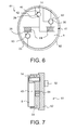
- FIGS. 6 and 7 show a further adjustment device 61, which instead of in the FIGS. 3 to 5 shown adjustment device 31 can be used to adjust the flange 8.
- components of the FIGS. 6 and 7 shown adjustment device 61, which with components of the in the FIGS. 3 to 5 shown adjustment device 31 are substantially identical in construction and function, provided with the same reference numerals.
- the Fig. 6 shows a plan view of the arranged on the flange 8 adjusting device 61 and the Fig. 7 shows a side view of the screwed with the flange 8 by means of screws 32 adjusting device 61 in a sectional view.
- adjustment device 31 has in the FIGS. 6 and 7 shown adjustment device 61 next to the base support 33, on which the boom 34 is arranged with the adjustment means 30, a plate 62 and a turntable, which by means of Screws 32 presses the base support 33 against the flange 8.
- the plate 62 is preferably circular.
- the plate 62 comprises the holes 35 of the flange 8 and the holes 34 of the base support 33 corresponding holes 63 through which the screws 32 are guided.
- the screw heads of the screws 32 press in the screwed state against the plate 62, whereby the plate 62 presses the base support 33 against the flange 8.
- the plate 62 is preferably made of metal.
- the contact force at the contact points 39-41 are also generated in the case of the present embodiment by at least one elastic element, in particular by two elastic elements 64 controlled.
- the elastic elements 64 are for example made of rubber or are designed for example as rubber blocks.
- the elastic elements 64 may also be designed as coil springs.
- the elastic elements 64 are, for example, unilaterally attached to the surface of the base support 33, e.g. attached by gluing, which faces the plate 62.
- the elastic members 64 may also be unilaterally attached to the surface of the plate 62, e.g. be attached by gluing, which faces the base support 33.
- two screws 32 are provided for releasably securing the base support 33 to the flange 8.
- two elastic elements 64 are provided, one of which is arranged in the region of one of the bores 34, 63 and the other in the region of the other bore 34, 63 of the base support 33 or the plate 62.
- the elastic elements 64 are supported on the additional plate 62 and press the base support 33 against the contact points 39-41.
- the plate 62 relative to the base support 33 by the friction between the screw heads of the screws 32 and the plate 62 is rotated so that the base support 33 is pressed by an increased deformation of the elastic members 64 against the abutment points 39- 41.
- the intermediate elastic elements 64 between the plate 62 and the base support 33 can be achieved that the increase in the contact force in the contact points 39-41 is less than in the FIGS. 3 to 5 This preserves the contact surfaces between the flange 8 and the base support 33 in the areas of the bearing points 39-41 and reduces their deformations, whereby an accuracy of a repeated adjustment (adjustment repetition accuracy) is improved.
Landscapes
- Engineering & Computer Science (AREA)
- Robotics (AREA)
- Mechanical Engineering (AREA)
- Manipulator (AREA)
Abstract
Description
- Die Erfindung betrifft einen Roboterarm eines Industrieroboters. Der Roboterarm umfasst einen Flansch und eine Justagevorrichtung zum Justieren des Flansches.
- Industrieroboter umfassen in der Regel einen Roboterarm und eine Steuervorrichtung. Der Roboterarm umfasst normalerweise einen Flansch zum Befestigen eines Endeffektors und mehrere, hintereinander angeordnete und über Gelenke verbundene Glieder, von denen eines der Glieder dem Flansch unmittelbar vorgelagert ist, wobei der Flansch bezüglich einer Achse relativ zu diesem Glied drehbar gelagert ist. Für eine zufriedenstellende Funktionsweise des Industrieroboters werden normalerweise die Stellungen der einzelnen Glieder und insbesondere die Stellung des Flansch relativ zu dem dem Flansch unmittelbar vorgelagerten Glieds justiert.
- Aufgabe der Erfindung ist es, einen Roboterarm mit einer zum Justieren des Flansches bezüglich dem dem Flansch unmittelbar vorgelagerten Glieds vorgesehenen verbesserten Justagevorrichtung anzugeben.
- Die Aufgabe der Erfindung wird gelöst durch einen Roboterarm eines Industrieroboters, aufweisend
- einen zum Befestigen eines Endeffektors vorgesehenen Flansch,
- mehrere, hintereinander angeordnete und über Gelenke verbundene Glieder, von denen eines der Glieder dem Flansch unmittelbar vorgelagert ist und der Flansch bezüglich einer Achse relativ zu diesem Glied drehbar gelagert ist, und
- eine zum Justieren des Flansches bezüglich dem dem Flansch unmittelbar vorgelagerten Glieds vorgesehene Justagevorrichtung, welche einen insbesondere mittels Schrauben lösbar am Flansch befestigbaren Grundträger mit einem am Grundträger angeordneten Justagemittel aufweist, welches mit einem an dem dem Flansch unmittelbar vorgelagerten Glied angeordneten Gegenjustagemittel zusammen wirkt.
- Der erfindungsgemäße Roboterarm umfasst demnach die Justagevorrichtung, welche wiederum den lösbar vom Flansch befestigbaren Grundträger aufweist. Somit kann die Justagevorrichtung zumindest größtenteils vom restlichen Roboterarm entfernt werden, was gerade bei beengten Platzverhältnissen zwischen dem Flansch und dem dem Flansch vorgelagerten Glied vorteilhaft ist.
- Am abnehmbaren bzw. lösbar befestigbaren Grundträger ist das Justagemittel befestigt, welches für ein Justieren des Flansches mit dem Gegenjustagemittel zusammen wirkt. Das Justagemittel ist z.B. als ein beweglicher Taststift mit Spitze oder als Justagepatrone und das Gegenjustagemittel als eine Justagekerbe ausgeführt. Die Justagekerbe bzw. das Gegenjustagemittel verbleibt vorzugsweise fest am relevanten Glied des erfindungsgemäßen Roboterarms, beispielsweise an einem Gehäuse des fraglichen Gliedes.
- Der Flansch des erfindungsgemäßen Roboterarms und der Grundträger der Justagevorrichtung weisen vorzugsweise jeweils eine Befestigungsoberfläche auf, die im befestigten Zustand des Grundträgers zueinander zugewandt sind. Die Befestigungsoberflächen sind insbesondere kreisförmig ausgebildet.
- Um eine möglichst genaue Justage des Flansches zu erreichen, ist es erstrebenswert, dass der Grundträger der Justagevorrichtung gegen Verschieben in zwei rechtwinklig zueinander stehenden Richtungen sowie durch Verdrehen um die Achse gesichert ist. Um dies zu erreichen, weisen nach einer Variante des erfindungsgemäßen Roboterarms die Befestigungsoberflächen wenigstens drei Anlagepunkte auf, die ausgebildet sind, ein Verdrehen und Verschieben des am Flansch befestigten Grundträgers relativ zum Flansch zumindest zu erschweren. Vorzugsweise sind drei Anlagepunkte auf drei winkelig zueinander stehenden ebenen oder gewölbten Funktionsflächen vorgesehen.
- Um die Anlagepunkte zu realisieren, kann beispielsweise der Grundträger im am Flansch befestigten Zustand über den Flansch übergestülpt sein, sodass der Grundträger seitlich den Flansch an einem der Anlagepunkte berührt. Es kann auch insbesondere rechtwinklig zur Befestigungsoberfläche des Flansches ein Stift herausragen, der im befestigten Zustand des Grundträgers in der Befestigungsoberfläche des Grundträgers angeordnete Kontaktflächen an zwei der Anlagepunkte berührt.
- Um die Kontaktkraft an den Anlagepunkten kontrolliert zu erzeugen, weist nach einer Ausführungsform des erfindungsgemäßen Roboterarms dieser wenigsten ein zwischen dem Grundträger und dem Flansch angeordnetes elastisches Element auf, welches sich am Flansch abstützt. Das wenigstens eine elastische Element drückt insbesondere den Grundträger im befestigten Zustand gegen die Anlagepunkte und/oder ist insbesondere einseitig am Grundträger z.B. mittels Klebens befestigt. Beim Festziehen der Schrauben wird der Grundträger gegenüber dem Flansch durch die Reibung zwischen den Schraubenköpfen der Schrauben und dem Grundträger so verdreht, dass der Grundträger gegen die Anlagepunkte gedrückt wird. Das wenigstens eine elastische Element ist vorzugsweise so bemessen, dass die Belastungen für die Anlagepunkte relativ gering sind, wodurch der Verschleiß relativ gering gehalten wird.
- Das wenigstens eine elastische Element ist beispielsweise aus Gummi gefertigt. Das wenigstens eine elastische Element ist beispielsweise als ein Gummiblock oder als eine Schraubenfeder ausgebildet.
- Nach einer Ausführungsform des erfindungsgemäßen Roboterarms kann dessen Justagevorrichtung eine Platte aufweisen, welche im befestigten Zustand mittels der Schrauben den Grundträger gegen den Flansch drückt. Die Platte ist vorzugsweise als eine Drehscheibe ausgebildet.
- Um gemäß dieser Ausführungsform die Kontaktkraft an den Anlagepunkten kontrolliert zu erzeugen, kann nach einer bevorzugten Ausführungsform des erfindungsgemäßen Roboterarms wenigsten ein zwischen dem Grundträger und der Platte angeordnetes elastisches Element vorgesehen sein, welches sich an der Platte abstützt. Das wenigstens eine elastische Element drückt insbesondere den Grundträger im befestigten Zustand gegen die Anlagepunkte. Das wenigstens eine elastische Element ist vorzugsweise einseitig am Grundträger oder an der Platte befestigt. Beim Festziehen der Schrauben bzw. der Verschraubung Platte/ Grundträger/ Flansch wird die Platte, die vorzugsweise als eine Drehscheibe ausgebildet ist, gegenüber dem Grundträger durch die Reibung zwischen den Schraubenköpfen und der Platte so verdreht, das der Grundträger über eine verstärkte Verformung des wenigstens einen elastischen Elementes gegen die Anlagepunkte gedrückt wird. Durch das wenigstens eine zwischengeschaltete elastische Element zwischen der Platte und dem Grundträger ist die Erhöhung der Kontaktkraft in den Anlagepunkten geringer. Dies schont die Kontaktflächen und reduziert die Verformungen, wodurch eine Justagewiederholgenauigkeit verbessert wird.
- Das wenigstens eine elastische Element ist beispielsweise aus Gummi gefertigt. Das wenigstens eine elastische Element ist beispielsweise als ein Gummiblock oder als eine Schraubenfeder ausgebildet.
- Ausführungsbeispiele der Erfindung sind exemplarisch in den beigefügten schematischen Zeichnungen dargestellt. Es zeigen:
- Fig. 1
- einen Industrieroboter mit einer Steuervorrichtung und einem Roboterarm, welcher einen Flansch zum Befestigen eines Endeffektors umfasst,
- Fig. 2
- eine Draufsicht des Flansches des Roboterarms,
- Fig. 3
- eine Draufsicht einer Justagevorrichtung zum Justieren des Flansches,
- Fig. 4
- eine Draufsicht der an den Flansch angeordneten Justagevorrichtung,
- Fig. 5
- eine Seitenansicht der mit dem Flansch verschraubten Justagevorrichtung in einer geschnittenen Darstellung,
- Fig. 6
- eine Draufsicht einer weiteren, an den Flansch angeordneten Justagevorrichtung und
- Fig. 7
- eine Seitenansicht der mit dem Flansch verschraubten weiteren Justagevorrichtung in einer geschnittenen Darstellung,
- Die
Fig. 1 zeigt in einer perspektivischen Darstellung einen Industrieroboter 1 mit einem Roboterarm 2 und einer Steuervorrichtung 9. - Der Roboterarm 2 umfasst im Falle des vorliegenden Ausführungsbeispiels mehrere, nacheinander angeordnete und mittels Gelenke verbundene Glieder. Bei den Gliedern handelt es sich insbesondere um ein ortsfestes oder bewegliches Gestell 3 und ein relativ zum Gestell 3 um eine vertikal verlaufende Achse A1 drehbar gelagertes Karussell 4. Weitere Glieder des Roboterarms 2 sind im Falle des vorliegenden Ausführungsbeispiels eine Schwinge 5, ein Ausleger 6 und eine vorzugsweise mehrachsige Roboterhand 7 mit einem Flansch 8 zum Befestigen eines nicht näher dargestellten Endeffektors. Die Schwinge 5 ist am unteren Ende z.B. an einem nicht näher dargestellten Schwingenlagerkopf auf dem Karussell 4 um eine vorzugsweise horizontale Achse A2 schwenkbar gelagert. Am oberen Ende der Schwinge 5 ist wiederum um eine ebenfalls vorzugsweise horizontale Achse A3 der Ausleger 6 schwenkbar gelagert. Dieser trägt endseitig die Roboterhand 7 mit ihren vorzugsweise drei Achsen A4, A5, A6. Die Roboterhand 7 umfasst insbesondere mehrere Glieder, von denen ein Glied 11 dem Flansch 8 unmittelbar vorgelagert ist, sodass der Flansch 8 bezüglich der Achse A6 drehbar zu diesem Glied 11 gelagert ist.
- Um den Industrieroboter 1 bzw. dessen Roboterarm 2 zu bewegen, umfasst dieser in allgemein bekannter Weise mit der Steuervorrichtung 9 verbundene Antriebe, die insbesondere elektrische Antriebe sind. In der
Figur 1 sind nur einige der elektrischen Motoren 10 dieser Antriebe gezeigt. Auf der Steuervorrichtung 9 läuft ein Rechenprogramm, mittels dem die Steuervorrichtung 9 im Betrieb des Industrieroboters 1 diesen beispielsweise derart ansteuert, dass der Flansch 8 oder ein sogenannter Tool Center Point eine vorbestimmte Bewegung ausführt. Gegebenfalls regelt die Steuervorrichtung 9 die Antriebe, wie dies im Prinzip dem Fachmann bekannt ist. Gegebenfalls sind die elektrischen Antriebe geregelte Antriebe und die Steuervorrichtung 9 erzeugt Soll-Signale für die geregelten Antriebe. - Im Falle des vorliegenden Ausführungsbeispiels ist es vorgesehen, den Flansch 8 bezüglich des dem Flansch 8 unmittelbar vorgelagerten Glieds 11 zu justieren. Eine Draufsicht des Flansches 8 und des dem Flansch 8 unmittelbar vorgelagerten Glieds 11 ist in der
Fig. 2 gezeigt. - Im Falle des vorliegenden Ausführungsbeispiels ist für das Justieren des Flansches 8 relativ zu dem dem Flansch 8 vorgelagerten Glied 11 eine in den
Figuren 3 bis 5 dargestellte Justagevorrichtung 31 vorgesehen, welche für das Justieren insbesondere anstelle des Endeffektors an den Flansch 8 mittels Schrauben 32 lösbar befestigt ist. DieFig. 3 zeigt die Justagevorrichtung 31 in einer Draufsicht, dieFig. 4 zeigt eine Draufsicht der an den Flansch 8 angeordneten Justagevorrichtung 31 und dieFig. 5 zeigt eine Seitenansicht der mit dem Flansch 8 mittels der Schrauben 32 verschraubten Justagevorrichtung 31 in einer geschnittenen Darstellung. - Im Falle des vorliegenden Ausführungsbeispiels umfasst die Justagevorrichtung 31 einen Grundträger 33, welcher Bohrungen 34 umfasst, um den Grundträger 33 mit dem Flansch 8 zu verschrauben. Der Flansch 8 umfasst für das Verschrauben den Bohrungen 34 des Grundträgers 33 entsprechende Bohrungen 35, welche mit den Gewinden der Schrauben 32 entsprechenden Gegengewinden versehen sind. Der Grundträger 33 ist vorzugsweise aus Metall.
- Im Falle des vorliegenden Ausführungsbeispiels umfasst die Justagevorrichtung 31 einen am Grundträger 33 angeordneten Ausleger 34, der mit einem Justagemittel 30 versehen ist. Der Ausleger 34 und der Grundträger 33 sind vorzugsweise aus einem Stück gefertigt. Das Justagemittel 30 ist z.B. als ein beweglicher Taststift mit Spitze ausgeführt.
- Im Falle des vorliegenden Ausführungsbeispiels umfasst das dem Flansch 8 vorgelagerte Glied 11 eine Hand oder einen Ausleger 12, welcher mit einem Gegenjustagemittel 13 versehen ist. Das Gegenjustagemittel 13, das z.B. als eine Kerbe ausgeführt ist, ist vorgesehen, dass für das Justieren des Flansches 8 dieses mit dem Justagemittel 30 zusammen wirkt. Das Justagemittel 30 ist insbesondere in nicht dargestellter Weise mit der Steuervorrichtung 9 verbunden, sodass diese von dem Justagemittel 30 stammenden und für das Justieren des Flansches 8 vorgesehenen Signale auszuwerten vermag. Der Ausleger 12 mit dem Gegenjustagemittel 13 ist z.B. am Gehäuse des Glieds 11 angeordnet.
- Um eine möglichst genaue Justage des Flansches 8 zu erreichen, ist es erstrebenswert, dass die Justagevorrichtung 31, insbesondere deren Grundträger 33 gegen Verschieben in zwei rechtwinklig zueinander stehenden Richtungen, angedeutet durch Doppelpfeile 36, 37 in der
Fig. 3 , sowie durch Verdrehen um die Achse A6, angedeutet durch einen Doppelpfeil 38 in derFig. 3 , gesichert ist. Um dies zu erreichen, sind im Falle des vorliegenden Ausführungsbeispiels drei Anlagepunkte, insbesondere ein erster Anlagepunkt 39, ein zweiter Anlagepunkt 40 und ein dritter Anlagepunkt 41 insbesondere auf drei winklig zueinander stehenden ebenen und/oder gewölbten Funktionsflächen vorgesehen. - Der erste Anlagepunkt 39 und der zweite Anlagepunkt 40 werden im Falle des vorliegenden Ausführungsbeispiels durch einen fest mit dem Flansch 8 verbundenen Paßstift 14 realisiert, gegen den der Grundträger 33 mit einer an den Grundträger 33 angeordneten Kerbe 42 drückt. Der Paßstift 14 ragt aus der dem Grundträger 33 zugewandten Oberfläche des Flansches 8 in Richtung der Achse A6, bezüglich derer der Flansch 8 drehbar gelagert ist, heraus. Die Kerbe 42 ist in der dem Flansch 8 zugewandten Oberfläche des Grundträgers 33 angeordnet.
- Der dritte Anlagepunkt 41 ist beispielsweise dadurch realisiert, indem der Grundträger 33 im Bereich des dritten Anlagepunktes 41 über den Rand des Flansches 8 gestülpt ist. Vorzugsweise sind der Flansch 8 und der Grundträger 33 kreisförmig und der Grundträger 33 ist umfänglich über den Flansch 8 gestülpt.
- Insbesondere der erste und der zweite Anlagepunkt 39, 40, bzw. die Kerbe 42 und der Paßstift 14 sind derart angeordnet, dass der Grundträger 33 beim Festdrehen der Schrauben 32 gegen den Paßstift 14 drückt. Die Anlagekraft an den Anlagepunkten 39-41 werden im Falle des vorliegenden Ausführungsbeispiels durch wenigstens ein elastisches Element, insbesondere durch ein erstes elastisches Element 43 und ein zweites elastisches Element 44 kontrolliert erzeugt.
- Die elastischen Elemente 43, 44 sind beispielsweise aus Gummi bzw. sind beispielsweise als Gummiblöcke ausgeführt. Die elastischen Elemente 43, 44 können auch als Schraubenfedern ausgeführt sein.
- Die elastischen Elemente 43, 44 stützen sich im Falle des vorliegenden Ausführungsbeispiels am Flansch 8 ab und drücken den Grundträger 33 gegen die Anlagepunkte 39-41. Insbesondere ist das erste elastische Element 43 zwischen dem Flansch 8 und dem Grundträger 33 angeordnet.
- Das erste elastische Element 43 ist vorzugsweise einseitig am Grundträger 33 insbesondere durch Kleben befestigt.
- Das zweite elastische Element 44 ist in dem Bereich des Grundträgers 33 angeordnet, vorzugsweise einseitig z.B. durch Kleben befestigt, in dem der Grundträger 33 über den Flansch 8 gestülpt ist. Insbesondere ist das zweite elastische Element 44 im Bereich des Grundträgers 33 angeordnet, der dem dritten Anlagepunkt 41 gegenüber liegt.
- Beim Festziehen der Schrauben 32 wird der Grundträger 33 gegenüber dem Flansch 8 durch eine Reibung zwischen den Schraubenköpfen der Schrauben 32 und dem Grundträger 33 so verdreht, dass der Grundträger 33 gegen die Anlagepunkte 39-41 gedrückt wird. Aufgrund der elastischen Elemente 43, 44 wird die Belastungen für die Anlagepunkte 39-41 verringert, wodurch der Verschleiß insbesondere des Grundträgers 33 verringert wird.
- Die
Figuren 6 und 7 zeigen eine weitere Justagevorrichtung 61, welche anstelle der in denFiguren 3 bis 5 gezeigten Justagevorrichtung 31 zum Justieren des Flansches 8 verwendet werden kann. Wenn nicht anders beschrieben, dann sind Bestandteile der in denFiguren 6 und 7 gezeigten Justagevorrichtung 61, die mit Bestandteilen der in denFiguren 3 bis 5 gezeigten Justagevorrichtung 31 im Wesentlichen bau-und funktionsgleich sind, mit denselben Bezugszeichen versehen. - Die
Fig. 6 zeigt eine Draufsicht der an den Flansch 8 angeordneten Justagevorrichtung 61 und dieFig. 7 zeigt eine Seitenansicht der mit dem Flansch 8 mittels der Schrauben 32 verschraubten Justagevorrichtung 61 in einer geschnittenen Darstellung. - Im Gegensatz zu der in den
Figuren 3 bis 5 gezeigten Justagevorrichtung 31 weist die in denFiguren 6 und 7 dargestellte Justagevorrichtung 61 neben dem Grundträger 33, an dem der Ausleger 34 mit dem Justagemittel 30 angeordnet ist, eine Platte 62 bzw. eine Drehscheibe auf, welche mittels der Schrauben 32 den Grundträger 33 gegen den Flansch 8 drückt. Die Platte 62 ist vorzugsweise kreisrund. Die Platte 62 umfasst den Bohrungen 35 des Flansches 8 bzw. den Bohrungen 34 des Grundträgers 33 entsprechende Bohrungen 63, durch die die Schrauben 32 geführt sind. Die Schraubenköpfe der Schrauben 32 drücken im verschraubten Zustand gegen die Platte 62, wodurch die Platte 62 den Grundträger 33 gegen den Flansch 8 drückt. Die Platte 62 ist vorzugsweise aus Metall. - Die Anlagekraft an den Anlagepunkten 39-41 werden im Falle des vorliegenden Ausführungsbeispiels ebenfalls durch wenigstens ein elastisches Element, insbesondere durch zwei elastische Elemente 64 kontrolliert erzeugt.
- Die elastischen Elemente 64 sind beispielsweise aus Gummi bzw. sind beispielsweise als Gummiblöcke ausgeführt. Die elastischen Elemente 64 können auch als Schraubenfedern ausgeführt sein. Die elastischen Elemente 64 sind beispielsweise einseitig an der Oberfläche des Grundträgers 33 z.B. durch Kleben befestigt, die der Platte 62 zugewandt ist. Die elastischen Elemente 64 können auch einseitig an der Oberfläche der Platte 62 z.B. durch Kleben befestigt sein, die dem Grundträger 33 zugewandt ist.
- Im Falle des vorliegenden Ausführungsbeispiels sind zwei Schrauben 32 zum lösbaren Befestigen des Grundträgers 33 am Flansch 8 vorgesehen. Insbesondere sind zwei elastische Elemente 64 vorgesehen, von denen eines im Bereich einer der Bohrungen 34, 63 und das andere im Bereich der anderen Bohrung 34, 63 des Grundträgers 33 bzw. der Platte 62 angeordnet ist.
- Die elastischen Elemente 64 stützen sich an der zusätzlichen Platte 62 ab und drücken den Grundträger 33 gegen die Anlagepunkte 39-41. Beim Festziehen der Schrauben 32 wird die Platte 62 gegenüber dem Grundträger 33 durch die Reibung zwischen den Schraubenköpfen der Schrauben 32 und der Platte 62 so verdreht, dass der Grundträger 33 über eine verstärkte Verformung der elastischen Elemente 64 gegen die Anlagepunkte 39- 41 gedrückt wird. Durch die zwischengeschalteten elastischen Elemente 64 zwischen der Platte 62 und dem Grundträger 33 kann erreicht werden, dass die Erhöhung der Kontaktkraft in den Anlagepunkten 39-41 geringer ist als bei der in den
Figuren 3 bis 5 dargestellten Justagevorrichtung 31. Dies schont die Kontaktflächen zwischen dem Flansch 8 und dem Grundträger 33 in den Bereichen der Anlagepunkte 39-41 und reduziert deren Verformungen, wodurch eine Genauigkeit einer wiederholten Justage (Justagewiederholgenauigkeit) verbessert wird.
Claims (10)
- Roboterarm eines Industrieroboters (1), aufweisend- einen zum Befestigen eines Endeffektors vorgesehenen Flansch (8),- mehrere, hintereinander angeordnete und über Gelenke verbundene Glieder (4-7, 11), von denen eines der Glieder dem Flansch (8) unmittelbar vorgelagert ist und der Flansch (8) bezüglich einer Achse (A6) relativ zu diesem Glied (11) drehbar gelagert ist, und- eine zum Justieren des Flansches (8) bezüglich dem dem Flansch (8) unmittelbar vorgelagerten Glieds (11) vorgesehene Justagevorrichtung (31, 61), welche einen insbesondere mittels Schrauben (32) lösbar am Flansch (8) befestigbaren Grundträger (33) mit einem am Grundträger (33) angeordneten Justagemittel (30) aufweist, welches mit einem an dem dem Flansch (8) unmittelbar vorgelagerten Glied (11) angeordneten Gegenjustagemittel (13) zusammen wirkt.
- Roboterarm nach Anspruch 1, dessen Flansch (8) und dessen Grundträger (33) jeweils eine insbesondere kreisförmig ausgebildete Befestigungsoberfläche aufweisen, die im befestigten Zustand des Grundträgers (33) zueinander zugewandt sind.
- Roboterarm nach Anspruch 2, bei dem die Befestigungsoberflächen wenigstens drei Anlagepunkte (39-41) aufweisen, die ausgebildet sind, ein Verdrehen und Verschieben des am Flansch (8) befestigten Grundträgers (33) relativ zum Flansch (8) zumindest zu erschweren.
- Roboterarm nach Anspruch 3, dessen Grundträger (33) im am Flansch (8) befestigten Zustand über den Flansch (8) übergestülpt ist, sodass der Grundträger (33) seitlich den Flansch (8) an einem der Anlagepunkte (41) berührt, und/oder insbesondere rechtwinklig zur Befestigungsoberfläche des Flansches (8) ein Stift (14) herausragt, der im befestigten Zustand des Grundträgers (33) in der Befestigungsoberfläche des Grundträgers (33) angeordnete Kontaktflächen an zwei der Anlagepunkte (39, 40) berührt.
- Roboterarm nach einem der Ansprüche 1 bis 4, aufweisend wenigsten ein zwischen dem Grundträger (33) und dem Flansch (8) angeordnetes elastisches Element (43, 44), welches sich am Flansch (8) abstützt, welches insbesondere den Grundträger (33) im befestigten Zustand gegen die Anlagepunkte (39-41) drückt und welches insbesondere einseitig am Grundträger (33) befestigt ist.
- Roboterarm nach Anspruch 5, bei dem das wenigstens eine elastische Element (43, 44) aus Gummi gefertigt ist, als ein Gummiblock ausgebildet ist oder als eine Schraubenfeder ausgebildet ist.
- Roboterarm nach einem der Ansprüche 1 bis 4, dessen Justagevorrichtung (61) eine Platte (62) aufweist, welche im befestigten Zustand mittels der Schrauben (32) den Grundträger (33) gegen den Flansch (8) drückt.
- Roboterarm nach Anspruch 7, aufweisend wenigsten ein zwischen dem Grundträger (33) und der Platte (62) angeordnetes elastisches Element (64), welches sich an der Platte (62) abstützt.
- Roboterarm nach Anspruch 8, bei dem das wenigstens eine elastische Element (64) den Grundträger (33) im befestigten Zustand gegen die Anlagepunkte (39-41) drückt, und/oder einseitig am Grundträger (33) oder an der Platte (62) befestigt ist.
- Roboterarm nach Anspruch 8 oder 9, bei dem das wenigstens eine elastische Element (64) aus Gummi gefertigt ist, als ein Gummiblock ausgebildet ist oder als eine Schraubenfeder ausgebildet ist.
Applications Claiming Priority (1)
| Application Number | Priority Date | Filing Date | Title |
|---|---|---|---|
| DE201210208098 DE102012208098A1 (de) | 2012-05-15 | 2012-05-15 | Roboterarm mit einer Justagevorrichtung |
Publications (3)
| Publication Number | Publication Date |
|---|---|
| EP2664423A2 true EP2664423A2 (de) | 2013-11-20 |
| EP2664423A3 EP2664423A3 (de) | 2017-11-08 |
| EP2664423B1 EP2664423B1 (de) | 2021-07-07 |
Family
ID=48236755
Family Applications (1)
| Application Number | Title | Priority Date | Filing Date |
|---|---|---|---|
| EP13166759.4A Active EP2664423B1 (de) | 2012-05-15 | 2013-05-07 | Roboterarm mit einer Justagevorrichtung |
Country Status (5)
| Country | Link |
|---|---|
| US (1) | US9003918B2 (de) |
| EP (1) | EP2664423B1 (de) |
| KR (1) | KR102036382B1 (de) |
| CN (1) | CN103419194B (de) |
| DE (1) | DE102012208098A1 (de) |
Families Citing this family (4)
| Publication number | Priority date | Publication date | Assignee | Title |
|---|---|---|---|---|
| US20100180711A1 (en) | 2009-01-19 | 2010-07-22 | Comau, Inc. | Robotic end effector system and method |
| DE102012208098A1 (de) * | 2012-05-15 | 2013-11-21 | Kuka Roboter Gmbh | Roboterarm mit einer Justagevorrichtung |
| JP7440240B2 (ja) * | 2019-10-23 | 2024-02-28 | ファナック株式会社 | ロボット |
| DE102020204272B3 (de) * | 2020-04-01 | 2021-07-22 | Kuka Deutschland Gmbh | Logistiksystem |
Family Cites Families (29)
| Publication number | Priority date | Publication date | Assignee | Title |
|---|---|---|---|---|
| JPS4932826B1 (de) * | 1970-12-26 | 1974-09-03 | ||
| JPH0742627Y2 (ja) * | 1991-03-12 | 1995-10-04 | エスエムシー株式会社 | 産業用ロボットのハンド交換装置 |
| US5261758A (en) * | 1992-07-27 | 1993-11-16 | The United States Of America As Represented By The Administrator Of The National Aeronautics And Space Administration | Split spline screw |
| DE9313310U1 (de) * | 1993-09-04 | 1994-11-17 | Kuka Schweißanlagen + Roboter GmbH, 86165 Augsburg | Werkzeugwechseleinrichtung für Manipulatoren |
| US5777267A (en) * | 1996-06-28 | 1998-07-07 | Abb Flexible Automation, Inc. | Harness assembly to provide signals to end effector |
| KR200145221Y1 (ko) * | 1996-07-30 | 1999-06-15 | 윤종용 | 로봇 회전관절 스토퍼 |
| DE29810345U1 (de) * | 1998-06-10 | 1998-08-20 | Seubert GmbH Bearbeitungstechnik, 35236 Breidenbach | Manuelle Werkzeugwechselvorrichtung |
| US6431018B1 (en) * | 1999-09-09 | 2002-08-13 | Fanuc Ltd. | Guide device for wiring member and/or piping member and robot with guide device |
| DE10132117C1 (de) * | 2001-07-03 | 2002-11-07 | Binzel Alex Schweisstech | Werkzeughalter zur Kupplung eines Werkzeuges, insbesondere eines Schweißbrenners oder Schneidbrenners, an einem Handlinggerät, insbesondere einem Industrieroboter |
| JP3689715B2 (ja) * | 2001-10-11 | 2005-08-31 | ビー・エル・オートテック株式会社 | ロボットアームカップリング装置 |
| JP4142304B2 (ja) * | 2001-10-22 | 2008-09-03 | 株式会社安川電機 | アーク溶接用ロボット |
| US6857174B2 (en) * | 2002-01-15 | 2005-02-22 | Denso Corporation | Robot hand for high load work |
| JP4055691B2 (ja) * | 2003-10-03 | 2008-03-05 | 松下電器産業株式会社 | 産業用ロボット |
| US8336419B2 (en) * | 2004-04-08 | 2012-12-25 | Fabworx Solutions, Inc. | Hub assembly for robotic arm having pin spacers |
| JP4134994B2 (ja) * | 2005-03-30 | 2008-08-20 | 松下電器産業株式会社 | 産業用ロボット |
| US7559590B1 (en) * | 2005-10-19 | 2009-07-14 | Western Digital Technologies, Inc. | Pressure transmission assembly for mounting to a robotic device having a rotatable end effector |
| US8290618B2 (en) * | 2007-03-05 | 2012-10-16 | CNOS Automations Software GmbH | Determining positions |
| US8459140B2 (en) * | 2007-04-18 | 2013-06-11 | Fabworx Solutions, Inc. | Adjustable wrist design for robotic arm |
| US7959399B2 (en) * | 2007-05-24 | 2011-06-14 | Seagate Technology Llc | End effector with collision detection sensor |
| US8221050B2 (en) * | 2008-03-07 | 2012-07-17 | Fabworx Solutions, Inc. | Robotic assembly providing leveling and joint stress reduction |
| CN101607398B (zh) * | 2008-06-18 | 2012-06-20 | 鸿富锦精密工业(深圳)有限公司 | 夹具更换装置 |
| US8029229B2 (en) * | 2008-07-25 | 2011-10-04 | Duane Aiken | Compensator for robotic arm |
| DE102008054501A1 (de) * | 2008-12-10 | 2010-06-17 | Kuka Roboter Gmbh | Industrieroboter und Verfahren zum Betreiben eines Industrieroboters |
| JP5195778B2 (ja) * | 2009-03-17 | 2013-05-15 | 株式会社デンソーウェーブ | ロボットの回転関節用配線装置 |
| US8992113B2 (en) * | 2009-06-08 | 2015-03-31 | Re2, Inc. | Robust manual connector for robotic arm end effector |
| CN102049784A (zh) * | 2009-10-30 | 2011-05-11 | 鸿富锦精密工业(深圳)有限公司 | 工业机器人 |
| DE102009053032B4 (de) * | 2009-11-12 | 2019-07-18 | Kuka Deutschland Gmbh | Manipulator mit einer frei tragende Arme aufweisenden Gewichtsausgleichsvorrichtung |
| CN102233584A (zh) * | 2010-04-27 | 2011-11-09 | 鸿富锦精密工业(深圳)有限公司 | 机器人臂部件 |
| DE102012208098A1 (de) * | 2012-05-15 | 2013-11-21 | Kuka Roboter Gmbh | Roboterarm mit einer Justagevorrichtung |
-
2012
- 2012-05-15 DE DE201210208098 patent/DE102012208098A1/de active Pending
- 2012-11-07 CN CN201210441238.9A patent/CN103419194B/zh active Active
-
2013
- 2013-04-16 US US13/863,899 patent/US9003918B2/en active Active
- 2013-05-01 KR KR1020130049106A patent/KR102036382B1/ko active Active
- 2013-05-07 EP EP13166759.4A patent/EP2664423B1/de active Active
Non-Patent Citations (1)
| Title |
|---|
| None |
Also Published As
| Publication number | Publication date |
|---|---|
| KR20130127917A (ko) | 2013-11-25 |
| EP2664423B1 (de) | 2021-07-07 |
| KR102036382B1 (ko) | 2019-10-24 |
| US9003918B2 (en) | 2015-04-14 |
| EP2664423A3 (de) | 2017-11-08 |
| CN103419194B (zh) | 2016-08-10 |
| US20130305868A1 (en) | 2013-11-21 |
| DE102012208098A1 (de) | 2013-11-21 |
| CN103419194A (zh) | 2013-12-04 |
Similar Documents
| Publication | Publication Date | Title |
|---|---|---|
| EP2815681B1 (de) | Verstellmechanik zur verstellung von beweglichen möbelteilen | |
| EP2743039B1 (de) | Roboterarm | |
| DE20114319U1 (de) | Einstellungsmechanismus | |
| DE202017107086U1 (de) | Einstellbarer Mechanismus einer Auslegerarmvorrichtung | |
| EP2664423B1 (de) | Roboterarm mit einer Justagevorrichtung | |
| EP3309648B1 (de) | Computeranordnung mit einem tabletteil und einem basisteil | |
| DE102009014553A1 (de) | Roboter der Aufhängungsbauart, dessen Roboterkörper längs Fahrschienen läuft | |
| EP2620242A1 (de) | Bearbeitungsvorrichtung für ein zahntechnisches Werkstück | |
| DE102010048435A1 (de) | Werkzeugmaschine, insbesondere Fräsmaschine | |
| DE102015121262A1 (de) | Werkzeugadapter für ein Roboterhandgelenk und Roboterhandgelenk mit daran angebrachtem Werkzeugadapter | |
| DE102019129756B4 (de) | Steuervorrichtung für eine Arbeitsmaschine | |
| EP4031412B1 (de) | Beleuchtungsvorrichtung für einen kraftfahrzeugscheinwerfer | |
| DE60219018T2 (de) | Gelenkverbindung | |
| DE112019005847T5 (de) | Antriebsvorrichtung | |
| EP1485762A2 (de) | Vorrichtung zur manipulation der winkellage eines gegenstands gegen ber einer festen struktur | |
| WO2013104355A2 (de) | Schwenkvorrichtung | |
| DE102013209111B4 (de) | Einspannvorrichtung, insbesondere zur Aufnahme und zum Einspannen eines Bauteils, sowie Einspannsystem mit einer solchen Einspannvorrichtung | |
| DE102018216951A1 (de) | Verstellbarer mechanischer Halter zur Feinjustage der Position eines Elements wie einer Linse | |
| DE102015012956A1 (de) | Gelenkstruktur, die einen Längenspielraum einer Versorgungsleitung optimieren kannn, und Industrieroboter mit der Gelenkstruktur | |
| EP1913282B1 (de) | Bremsvorrichtung für einen elektromotor | |
| DE102015012561B4 (de) | Antriebsmechanismus einer Spritzgießmaschine | |
| WO2011045366A1 (de) | Vorrichtung zur befestigung eines tragrahmens | |
| EP2674248B1 (de) | Finishvorrichtung | |
| DE202021106714U1 (de) | Halterung für Fahrradzubehör | |
| DE102019129757A1 (de) | Schaltblock einer Steuervorrichtung für eine Arbeitsmaschine |
Legal Events
| Date | Code | Title | Description |
|---|---|---|---|
| PUAI | Public reference made under article 153(3) epc to a published international application that has entered the european phase |
Free format text: ORIGINAL CODE: 0009012 |
|
| AK | Designated contracting states |
Kind code of ref document: A2 Designated state(s): AL AT BE BG CH CY CZ DE DK EE ES FI FR GB GR HR HU IE IS IT LI LT LU LV MC MK MT NL NO PL PT RO RS SE SI SK SM TR |
|
| AX | Request for extension of the european patent |
Extension state: BA ME |
|
| PUAL | Search report despatched |
Free format text: ORIGINAL CODE: 0009013 |
|
| AK | Designated contracting states |
Kind code of ref document: A3 Designated state(s): AL AT BE BG CH CY CZ DE DK EE ES FI FR GB GR HR HU IE IS IT LI LT LU LV MC MK MT NL NO PL PT RO RS SE SI SK SM TR |
|
| AX | Request for extension of the european patent |
Extension state: BA ME |
|
| RIC1 | Information provided on ipc code assigned before grant |
Ipc: B25J 9/10 20060101ALI20171004BHEP Ipc: B25J 19/00 20060101AFI20171004BHEP |
|
| STAA | Information on the status of an ep patent application or granted ep patent |
Free format text: STATUS: REQUEST FOR EXAMINATION WAS MADE |
|
| 17P | Request for examination filed |
Effective date: 20180504 |
|
| RBV | Designated contracting states (corrected) |
Designated state(s): AL AT BE BG CH CY CZ DE DK EE ES FI FR GB GR HR HU IE IS IT LI LT LU LV MC MK MT NL NO PL PT RO RS SE SI SK SM TR |
|
| RAP1 | Party data changed (applicant data changed or rights of an application transferred) |
Owner name: KUKA DEUTSCHLAND GMBH |
|
| GRAP | Despatch of communication of intention to grant a patent |
Free format text: ORIGINAL CODE: EPIDOSNIGR1 |
|
| STAA | Information on the status of an ep patent application or granted ep patent |
Free format text: STATUS: GRANT OF PATENT IS INTENDED |
|
| INTG | Intention to grant announced |
Effective date: 20210210 |
|
| RIN1 | Information on inventor provided before grant (corrected) |
Inventor name: NITZ, GERNOT Inventor name: LIEBL, FRANZ |
|
| GRAS | Grant fee paid |
Free format text: ORIGINAL CODE: EPIDOSNIGR3 |
|
| GRAA | (expected) grant |
Free format text: ORIGINAL CODE: 0009210 |
|
| STAA | Information on the status of an ep patent application or granted ep patent |
Free format text: STATUS: THE PATENT HAS BEEN GRANTED |
|
| AK | Designated contracting states |
Kind code of ref document: B1 Designated state(s): AL AT BE BG CH CY CZ DE DK EE ES FI FR GB GR HR HU IE IS IT LI LT LU LV MC MK MT NL NO PL PT RO RS SE SI SK SM TR |
|
| REG | Reference to a national code |
Ref country code: GB Ref legal event code: FG4D Free format text: NOT ENGLISH |
|
| RIN1 | Information on inventor provided before grant (corrected) |
Inventor name: NITZ, GERNOT Inventor name: LIEBL, FRANZ |
|
| REG | Reference to a national code |
Ref country code: AT Ref legal event code: REF Ref document number: 1408101 Country of ref document: AT Kind code of ref document: T Effective date: 20210715 |
|
| REG | Reference to a national code |
Ref country code: DE Ref legal event code: R096 Ref document number: 502013015815 Country of ref document: DE |
|
| REG | Reference to a national code |
Ref country code: IE Ref legal event code: FG4D Free format text: LANGUAGE OF EP DOCUMENT: GERMAN |
|
| REG | Reference to a national code |
Ref country code: LT Ref legal event code: MG9D |
|
| REG | Reference to a national code |
Ref country code: NL Ref legal event code: MP Effective date: 20210707 |
|
| PG25 | Lapsed in a contracting state [announced via postgrant information from national office to epo] |
Ref country code: HR Free format text: LAPSE BECAUSE OF FAILURE TO SUBMIT A TRANSLATION OF THE DESCRIPTION OR TO PAY THE FEE WITHIN THE PRESCRIBED TIME-LIMIT Effective date: 20210707 Ref country code: SE Free format text: LAPSE BECAUSE OF FAILURE TO SUBMIT A TRANSLATION OF THE DESCRIPTION OR TO PAY THE FEE WITHIN THE PRESCRIBED TIME-LIMIT Effective date: 20210707 Ref country code: ES Free format text: LAPSE BECAUSE OF FAILURE TO SUBMIT A TRANSLATION OF THE DESCRIPTION OR TO PAY THE FEE WITHIN THE PRESCRIBED TIME-LIMIT Effective date: 20210707 Ref country code: FI Free format text: LAPSE BECAUSE OF FAILURE TO SUBMIT A TRANSLATION OF THE DESCRIPTION OR TO PAY THE FEE WITHIN THE PRESCRIBED TIME-LIMIT Effective date: 20210707 Ref country code: NL Free format text: LAPSE BECAUSE OF FAILURE TO SUBMIT A TRANSLATION OF THE DESCRIPTION OR TO PAY THE FEE WITHIN THE PRESCRIBED TIME-LIMIT Effective date: 20210707 Ref country code: NO Free format text: LAPSE BECAUSE OF FAILURE TO SUBMIT A TRANSLATION OF THE DESCRIPTION OR TO PAY THE FEE WITHIN THE PRESCRIBED TIME-LIMIT Effective date: 20211007 Ref country code: PT Free format text: LAPSE BECAUSE OF FAILURE TO SUBMIT A TRANSLATION OF THE DESCRIPTION OR TO PAY THE FEE WITHIN THE PRESCRIBED TIME-LIMIT Effective date: 20211108 Ref country code: RS Free format text: LAPSE BECAUSE OF FAILURE TO SUBMIT A TRANSLATION OF THE DESCRIPTION OR TO PAY THE FEE WITHIN THE PRESCRIBED TIME-LIMIT Effective date: 20210707 Ref country code: LT Free format text: LAPSE BECAUSE OF FAILURE TO SUBMIT A TRANSLATION OF THE DESCRIPTION OR TO PAY THE FEE WITHIN THE PRESCRIBED TIME-LIMIT Effective date: 20210707 Ref country code: BG Free format text: LAPSE BECAUSE OF FAILURE TO SUBMIT A TRANSLATION OF THE DESCRIPTION OR TO PAY THE FEE WITHIN THE PRESCRIBED TIME-LIMIT Effective date: 20211007 |
|
| PG25 | Lapsed in a contracting state [announced via postgrant information from national office to epo] |
Ref country code: PL Free format text: LAPSE BECAUSE OF FAILURE TO SUBMIT A TRANSLATION OF THE DESCRIPTION OR TO PAY THE FEE WITHIN THE PRESCRIBED TIME-LIMIT Effective date: 20210707 Ref country code: LV Free format text: LAPSE BECAUSE OF FAILURE TO SUBMIT A TRANSLATION OF THE DESCRIPTION OR TO PAY THE FEE WITHIN THE PRESCRIBED TIME-LIMIT Effective date: 20210707 Ref country code: GR Free format text: LAPSE BECAUSE OF FAILURE TO SUBMIT A TRANSLATION OF THE DESCRIPTION OR TO PAY THE FEE WITHIN THE PRESCRIBED TIME-LIMIT Effective date: 20211008 |
|
| REG | Reference to a national code |
Ref country code: DE Ref legal event code: R097 Ref document number: 502013015815 Country of ref document: DE |
|
| PG25 | Lapsed in a contracting state [announced via postgrant information from national office to epo] |
Ref country code: DK Free format text: LAPSE BECAUSE OF FAILURE TO SUBMIT A TRANSLATION OF THE DESCRIPTION OR TO PAY THE FEE WITHIN THE PRESCRIBED TIME-LIMIT Effective date: 20210707 |
|
| PLBE | No opposition filed within time limit |
Free format text: ORIGINAL CODE: 0009261 |
|
| STAA | Information on the status of an ep patent application or granted ep patent |
Free format text: STATUS: NO OPPOSITION FILED WITHIN TIME LIMIT |
|
| PG25 | Lapsed in a contracting state [announced via postgrant information from national office to epo] |
Ref country code: SM Free format text: LAPSE BECAUSE OF FAILURE TO SUBMIT A TRANSLATION OF THE DESCRIPTION OR TO PAY THE FEE WITHIN THE PRESCRIBED TIME-LIMIT Effective date: 20210707 Ref country code: SK Free format text: LAPSE BECAUSE OF FAILURE TO SUBMIT A TRANSLATION OF THE DESCRIPTION OR TO PAY THE FEE WITHIN THE PRESCRIBED TIME-LIMIT Effective date: 20210707 Ref country code: RO Free format text: LAPSE BECAUSE OF FAILURE TO SUBMIT A TRANSLATION OF THE DESCRIPTION OR TO PAY THE FEE WITHIN THE PRESCRIBED TIME-LIMIT Effective date: 20210707 Ref country code: EE Free format text: LAPSE BECAUSE OF FAILURE TO SUBMIT A TRANSLATION OF THE DESCRIPTION OR TO PAY THE FEE WITHIN THE PRESCRIBED TIME-LIMIT Effective date: 20210707 Ref country code: CZ Free format text: LAPSE BECAUSE OF FAILURE TO SUBMIT A TRANSLATION OF THE DESCRIPTION OR TO PAY THE FEE WITHIN THE PRESCRIBED TIME-LIMIT Effective date: 20210707 Ref country code: AL Free format text: LAPSE BECAUSE OF FAILURE TO SUBMIT A TRANSLATION OF THE DESCRIPTION OR TO PAY THE FEE WITHIN THE PRESCRIBED TIME-LIMIT Effective date: 20210707 |
|
| 26N | No opposition filed |
Effective date: 20220408 |
|
| PG25 | Lapsed in a contracting state [announced via postgrant information from national office to epo] |
Ref country code: IT Free format text: LAPSE BECAUSE OF FAILURE TO SUBMIT A TRANSLATION OF THE DESCRIPTION OR TO PAY THE FEE WITHIN THE PRESCRIBED TIME-LIMIT Effective date: 20210707 |
|
| REG | Reference to a national code |
Ref country code: CH Ref legal event code: PL |
|
| REG | Reference to a national code |
Ref country code: BE Ref legal event code: MM Effective date: 20220531 |
|
| PG25 | Lapsed in a contracting state [announced via postgrant information from national office to epo] |
Ref country code: MC Free format text: LAPSE BECAUSE OF FAILURE TO SUBMIT A TRANSLATION OF THE DESCRIPTION OR TO PAY THE FEE WITHIN THE PRESCRIBED TIME-LIMIT Effective date: 20210707 Ref country code: LU Free format text: LAPSE BECAUSE OF NON-PAYMENT OF DUE FEES Effective date: 20220507 Ref country code: LI Free format text: LAPSE BECAUSE OF NON-PAYMENT OF DUE FEES Effective date: 20220531 Ref country code: CH Free format text: LAPSE BECAUSE OF NON-PAYMENT OF DUE FEES Effective date: 20220531 |
|
| PG25 | Lapsed in a contracting state [announced via postgrant information from national office to epo] |
Ref country code: IE Free format text: LAPSE BECAUSE OF NON-PAYMENT OF DUE FEES Effective date: 20220507 |
|
| PG25 | Lapsed in a contracting state [announced via postgrant information from national office to epo] |
Ref country code: BE Free format text: LAPSE BECAUSE OF NON-PAYMENT OF DUE FEES Effective date: 20220531 |
|
| P01 | Opt-out of the competence of the unified patent court (upc) registered |
Effective date: 20230528 |
|
| REG | Reference to a national code |
Ref country code: AT Ref legal event code: MM01 Ref document number: 1408101 Country of ref document: AT Kind code of ref document: T Effective date: 20220507 |
|
| PG25 | Lapsed in a contracting state [announced via postgrant information from national office to epo] |
Ref country code: AT Free format text: LAPSE BECAUSE OF NON-PAYMENT OF DUE FEES Effective date: 20220507 |
|
| PG25 | Lapsed in a contracting state [announced via postgrant information from national office to epo] |
Ref country code: HU Free format text: LAPSE BECAUSE OF FAILURE TO SUBMIT A TRANSLATION OF THE DESCRIPTION OR TO PAY THE FEE WITHIN THE PRESCRIBED TIME-LIMIT; INVALID AB INITIO Effective date: 20130507 |
|
| PG25 | Lapsed in a contracting state [announced via postgrant information from national office to epo] |
Ref country code: MK Free format text: LAPSE BECAUSE OF FAILURE TO SUBMIT A TRANSLATION OF THE DESCRIPTION OR TO PAY THE FEE WITHIN THE PRESCRIBED TIME-LIMIT Effective date: 20210707 Ref country code: CY Free format text: LAPSE BECAUSE OF FAILURE TO SUBMIT A TRANSLATION OF THE DESCRIPTION OR TO PAY THE FEE WITHIN THE PRESCRIBED TIME-LIMIT Effective date: 20210707 |
|
| PG25 | Lapsed in a contracting state [announced via postgrant information from national office to epo] |
Ref country code: TR Free format text: LAPSE BECAUSE OF FAILURE TO SUBMIT A TRANSLATION OF THE DESCRIPTION OR TO PAY THE FEE WITHIN THE PRESCRIBED TIME-LIMIT Effective date: 20210707 |
|
| PG25 | Lapsed in a contracting state [announced via postgrant information from national office to epo] |
Ref country code: MT Free format text: LAPSE BECAUSE OF FAILURE TO SUBMIT A TRANSLATION OF THE DESCRIPTION OR TO PAY THE FEE WITHIN THE PRESCRIBED TIME-LIMIT Effective date: 20210707 |
|
| PGFP | Annual fee paid to national office [announced via postgrant information from national office to epo] |
Ref country code: DE Payment date: 20250311 Year of fee payment: 13 |
|
| PGFP | Annual fee paid to national office [announced via postgrant information from national office to epo] |
Ref country code: GB Payment date: 20260312 Year of fee payment: 14 |
|
| PGFP | Annual fee paid to national office [announced via postgrant information from national office to epo] |
Ref country code: FR Payment date: 20260309 Year of fee payment: 14 |